Embed Size (px)
Citation preview
PA-25-V.43 Maintenance Manual
PA-43 -1
PA-25 V.43
MAINTENANCE MANUAL
PA-25-V.43 Maintenance Manual
PA-43 -2
Index
0. INTRODUCTION ....................................................................................................................... 3
0.1. GENERAL INFORMATION....................................................................................................... 3
0.2. SAFETY STANDARDS ............................................................................................................ 4
0.2.1. Signs present on the machine .............................................................................. 5
0.2.2. General precautions to prevent danger ............................................................... 5
0.3. PERSONNEL TRAINING ......................................................................................................... 6
0.3.1. Maintenance............................................................................................................ 7
0.4. DANGEROUS AREAS IN THE MACHINE .................................................................................... 7
0.4.1. Moving conveyor belts .......................................................................................... 8
0.4.2. Troughs ................................................................................................................... 8
1. GENERAL CHARACTERISTICS ....................................................................................................... 9
2. MACHINE DESCRIPTION.............................................................................................................. 11
2.1. AUTOMATIC WEIGHING MACHINE......................................................................................... 11
2.1.1. Bedplate ................................................................................................................ 11
2.1.2. Feeder conveyor................................................................................................... 11
2.1.3. Loading sensor cell and troughs........................................................................ 11
2.1.4. Exit conveyor........................................................................................................ 11
2.1.5. Controls and electric unit .................................................................................... 11
2.1.6. Elevator conveyor ................................................................................................ 12
3. INSTALLATION AND COMMISSIONING ........................................................................................... 13
3.1. LEVELLING ........................................................................................................................ 13
3.2. CONNECTING PRODUCT ELEVATOR TO WEIGHING MACHINE................................................ 13
3.3. CONNECTION TO THE MAINS ............................................................................................... 14
3.3.1. Verifying motor rotation direction ...................................................................... 15
3.4. CHANGING THE VOLTAGE................................................................................................... 16
3.5. CONTROLS........................................................................................................................ 17
4. CONNECTION TO PACKING MACHINES AND FEEDERS .................................................................... 19
4.1. CONNECTION AND LEVELLING VIS-À-VIS THE PACKING MACHINE............................................ 19
4.2. INTERCONNECTING CONTROL SIGNALS BETWEEN MACHINES ................................................ 20
4.3. CONNECTION TO THE POWER SUPPLY ................................................................................. 21
4.3.1. Connection to return or distributor belt............................................................. 22
4.3.2. Connection to feeding tank................................................................................. 23
4.4. ADJUSTING THE ELEVATOR CONVEYOR HOPPER .................................................................. 24
4.5. BLOCKING TORQUE LIMITING ADJUSTMENT .......................................................................... 25
4.6. TIGHTENING AND CENTRING THE BELTS............................................................................... 26
5. ELECTRICAL WIRING................................................................................................................... 27
PA-25-V.43 Maintenance Manual
PA-43 -3
0. INTRODUCTION
0.1. GENERAL INFORMATION
This manual is an integral part of the machine, and contains information that is necessary for ensuring that the machine is used correctly.
This manual is intended for qualified technical personnel. It is recommended that all extraordinary operations concerning installation, commissioning, maintenance and where applicable, repair and parts replacement, are to be carried out by the Technical Service at DAUMAR, SA., or the authorised distributor.
The operators working on the machine must consult this manual before carrying out any ordinary or extraordinary operation.
DAUMAR, SA. is not responsible for any damage to people, objects or the environment, arising from an improper use of the machine, inexpertness, imprudence or negligence with respect to the indications contained in this manual.
DAUMAR, SA. is not responsible for any damage to people, objects or the environment, if non-original spare parts are used.
Any modification must be agreed beforehand with the manufacturer.
The drawings used as examples in this manual may be different from those parts of the machine that are represented. Nevertheless, the information contained herein, and machine safety, are guaranteed.
Following its policy of continual research and development, without prior notification, DAUMAR,S.A. can introduce modifications to update its products.
Information property
This manual contains information that is the property of DAUMAR, SA.
PA-25-V.43 Maintenance Manual
PA-43 -4
0.2. SAFETY STANDARDS
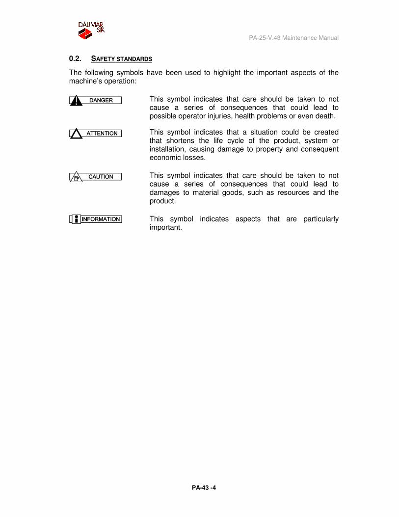
The following symbols have been used to highlight the important aspects of the machine’s operation:
This symbol indicates that care should be taken to not cause a series of consequences that could lead to possible operator injuries, health problems or even death.
This symbol indicates that a situation could be created that shortens the life cycle of the product, system or installation, causing damage to property and consequent economic losses.
This symbol indicates that care should be taken to not cause a series of consequences that could lead to damages to material goods, such as resources and the product.
This symbol indicates aspects that are particularly important.
PA-25-V.43 Maintenance Manual
PA-43 -5
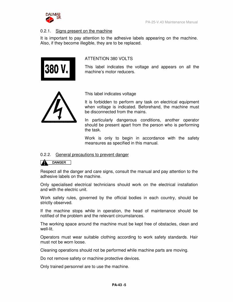
0.2.1. Signs present on the machine
It is important to pay attention to the adhesive labels appearing on the machine. Also, if they become illegible, they are to be replaced.
ATTENTION 380 VOLTS
This label indicates the voltage and appears on all the machine’s motor reducers.
This label indicates voltage
It is forbidden to perform any task on electrical equipment when voltage is indicated. Beforehand, the machine must be disconnected from the mains.
In particularly dangerous conditions, another operator should be present apart from the person who is performing the task.
Work is only to begin in accordance with the safety meansures as specified in this manual.
0.2.2. General precautions to prevent danger
Respect all the danger and care signs, consult the manual and pay attention to the adhesive labels on the machine.
Only specialised electrical technicians should work on the electrical installation and with the electric unit.
Work safety rules, governed by the official bodies in each country, should be strictly observed.
If the machine stops while in operation, the head of maintenance should be notified of the problem and the relevant circumstances.
The working space around the machine must be kept free of obstacles, clean and well-lit.
Operators must wear suitable clothing according to work safety standards. Hair must not be worn loose.
Cleaning operations should not be performed while machine parts are moving.
Do not remove safety or machine protective devices.
Only trained personnel are to use the machine.
PA-25-V.43 Maintenance Manual
PA-43 -6
0.3. PERSONNEL TRAINING
The operators using this machine must be duly qualified and trained in the machine’s ordinary operation and use. Operators should be trained by qualified technicians once the machine is installed in its final location, or on the manufacturer/distributor’s premises.
If machine operators do not receive sufficient information or training, the machine may be used inappropriately, causing accidents and machine faults.
PA-25-V.43 Maintenance Manual
PA-43 -7
0.3.1. Maintenance
The setting, lubricatin and conservation points are located outside the dangerous areas, so that these operations can be carried out when the machine is stopped.
All cleaning operations inside and outside the machine can be carried out safely when the machine is stopped.
Extraordinary maintenance operations are to be carried out by specialist technicians, who have the necessary equipment and have been trained beforehand in the machine’s operation equipado and the safety devices.
A T T E N T I O N
THESE OPERATIONS ARE ALWAYS TO BE CARRIED OUT WHEN THE MACHINE IS STOPPED AND THE ELECTRICAL AND PNEUMATIC ENERGY SOURCES ARE DISCONNECTED. ALSO ONLY ONE PERSON IS TO PERFORM THESE OPERATIONS.
0.4. DANGEROUS AREAS IN THE MACHINE
A dangerous area is any space inside and/or around a machine where somebody is exposed to a health risk.
In the PA-25 automatic weighing machine, all the safety measures have been adopted with respect to providing protective devices to all moving and accessible mechanisms.
According to this PA-25 weighing machine’s operation, the “exposed person” refers only to the “operator” responsible for starting and stopping the machine.
Under normal operating conditions, the operator must not be exposed to the dangerous areas in the machine, because the machine normally operates automatically from the time the product is loaded until it reaches the packing machines.
Under normal, expected operation conditions, i.e.: with a continual weighing process, the PA-25 weighing machine does not expose operators to any kind of risk. Any machine risks have been eliminated or reduced owing to the machine’s safety-orientated design, placing guards and protective devices, where appropriate, in the risk areas during maintenance and setting.
However, generally speaking, there are some areas in the machine that represent a residual danger which, owing to their nature, cannot be provided with any protective device. These areas may cause injuries by dragging, trapping or catching the operator’s limbs. Therefore, the operators using the machine must be
PA-25-V.43 Maintenance Manual
PA-43 -8
trained in the various danger situations, which may cause injuries owing to the mechanical action of the various machine elements. When the machine is on, do not touch, place hands inside, handle or rest on these areas, which are indicated below:
- Moving conveyor belts
- Troughs
0.4.1. Moving conveyor belts
These are located at the bottom of the machine, for the product exit (exit conveyor), and at the top, for the product inlet (feeder conveyor).
The product elevator also has a conveyor belt which lifts the product on to the product conveyor belt for entering the weighing machine.
The conveyor belts are protected on the sides to prevent gashes caused in the vicinity of the driving rollers.
The belts can cause injury by dragging, trapping or catching the operator’s limbs. The operators using the machine must be trained in the various danger situations, which may cause injuries owing to the mechanical action of the various machine elements. Do not place hands or rest on these areas.
0.4.2. Troughs
The troughs are located around a plate at the top of the machine. They are used to hold the product that is to be weighed, and move in a circular motion around the plate that supports them. It is difficult for operators to access the troughs because, apart from the protective devices provided, the only part that is not protected, for operating requirements, is the top and owing to its height it is difficult to access.
The troughs can cause injury by dragging, trapping and catching the operator’s limbs. The operators using the machine must be trained in the various danger situations, which may cause injuries owing to the mechanical action of the various machine elements. When the machine is on, it is strictly forbidden to handle or place hands in this area.
PA-25-V.43 Maintenance Manual
PA-43 -9
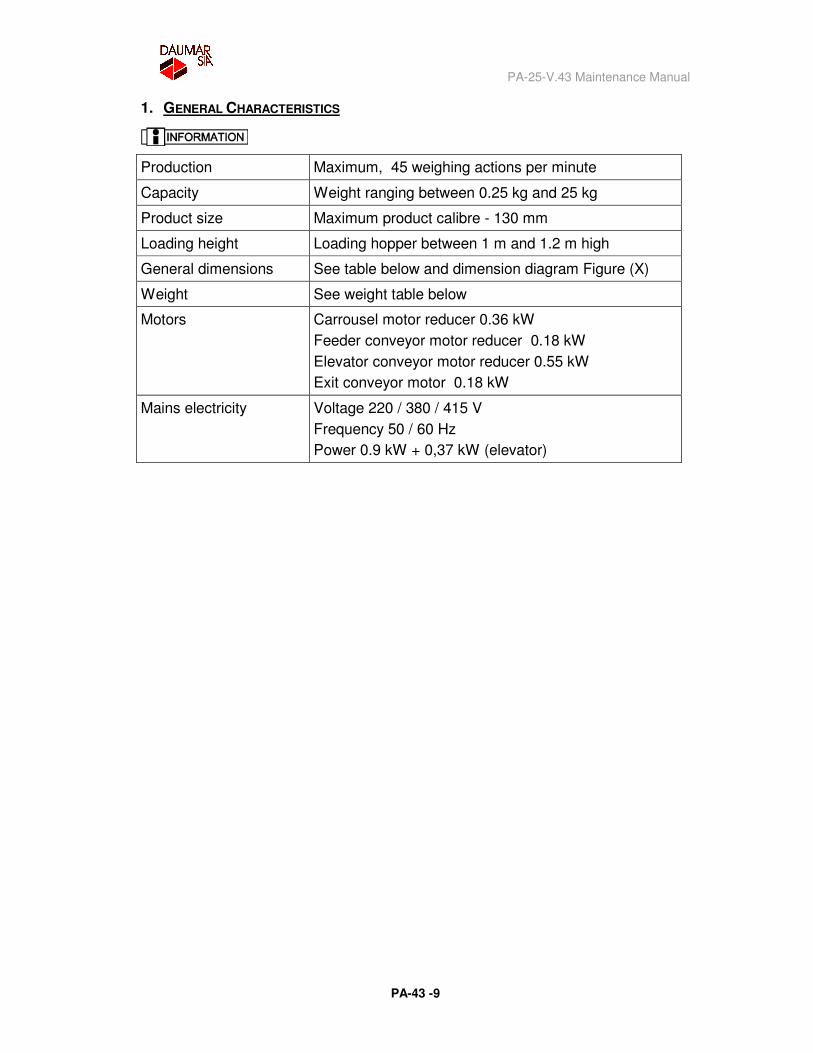
1. GENERAL CHARACTERISTICS
Production Maximum, 45 weighing actions per minute
Capacity Weight ranging between 0.25 kg and 25 kg
Product size Maximum product calibre - 130 mm
Loading height Loading hopper between 1 m and 1.2 m high
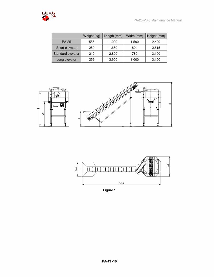
General dimensions See table below and dimension diagram Figure (X)
Weight See weight table below
Motors Carrousel motor reducer 0.36 kW Feeder conveyor motor reducer 0.18 kW Elevator conveyor motor reducer 0.55 kW Exit conveyor motor 0.18 kW
Mains electricity Voltage 220 / 380 / 415 V Frequency 50 / 60 Hz Power 0.9 kW + 0,37 kW (elevator)
PA-25-V.43 Maintenance Manual
PA-43 -10
Weight (kg) Length (mm) Width (mm) Height (mm)
PA-25 555 1.900 1.500 2.400
Short elevator 259 1.650 804 2.815
Standard elevator 210 2.800 780 3.100
Long elevator 259 3.900 1.000 3.100
Figure 1
PA-25-V.43 Maintenance Manual
PA-43 -11
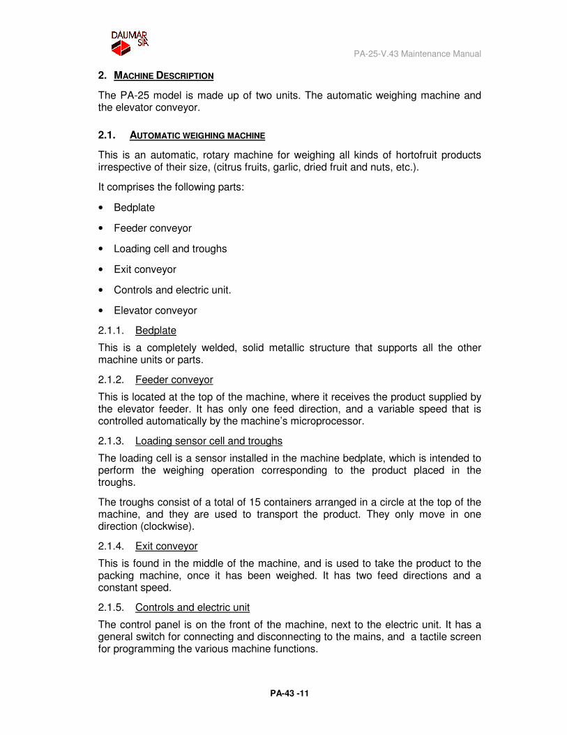
2. MACHINE DESCRIPTION
The PA-25 model is made up of two units. The automatic weighing machine and the elevator conveyor.
2.1. AUTOMATIC WEIGHING MACHINE
This is an automatic, rotary machine for weighing all kinds of hortofruit products irrespective of their size, (citrus fruits, garlic, dried fruit and nuts, etc.).
It comprises the following parts:
• Bedplate
• Feeder conveyor
• Loading cell and troughs
• Exit conveyor
• Controls and electric unit.
• Elevator conveyor
2.1.1. Bedplate
This is a completely welded, solid metallic structure that supports all the other machine units or parts.
2.1.2. Feeder conveyor
This is located at the top of the machine, where it receives the product supplied by the elevator feeder. It has only one feed direction, and a variable speed that is controlled automatically by the machine’s microprocessor.
2.1.3. Loading sensor cell and troughs
The loading cell is a sensor installed in the machine bedplate, which is intended to perform the weighing operation corresponding to the product placed in the troughs.
The troughs consist of a total of 15 containers arranged in a circle at the top of the machine, and they are used to transport the product. They only move in one direction (clockwise).
2.1.4. Exit conveyor
This is found in the middle of the machine, and is used to take the product to the packing machine, once it has been weighed. It has two feed directions and a constant speed.
2.1.5. Controls and electric unit
The control panel is on the front of the machine, next to the electric unit. It has a general switch for connecting and disconnecting to the mains, and a tactile screen for programming the various machine functions.
PA-25-V.43 Maintenance Manual
PA-43 -12
2.1.6. Elevator conveyor
This is an auxiliary unit to the weighing machine and the two machine parts are electrically connected. It is used to lift the product onto the feeder conveyor, and has only one feed direction. Its speed is constant but intermittent, since it observes the signals given by the weighing machine.
PA-25-V.43 Maintenance Manual
PA-43 -13
3. INSTALLATION AND COMMISSIONING
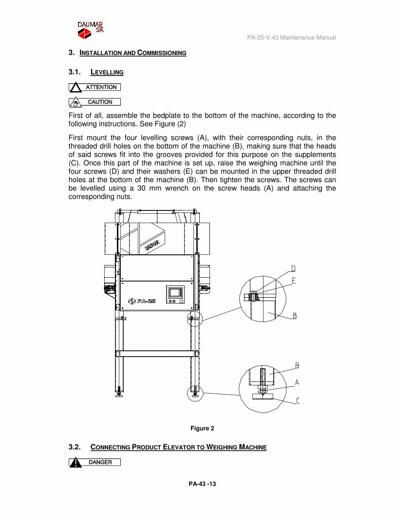
3.1. LEVELLING
First of all, assemble the bedplate to the bottom of the machine, according to the following instructions. See Figure (2)
First mount the four levelling screws (A), with their corresponding nuts, in the threaded drill holes on the bottom of the machine (B), making sure that the heads of said screws fit into the grooves provided for this purpose on the supplements (C). Once this part of the machine is set up, raise the weighing machine until the four screws (D) and their washers (E) can be mounted in the upper threaded drill holes at the bottom of the machine (B). Then tighten the screws. The screws can be levelled using a 30 mm wrench on the screw heads (A) and attaching the corresponding nuts.
Figure 2
3.2. CONNECTING PRODUCT ELEVATOR TO WEIGHING MACHINE
PA-25-V.43 Maintenance Manual
PA-43 -14
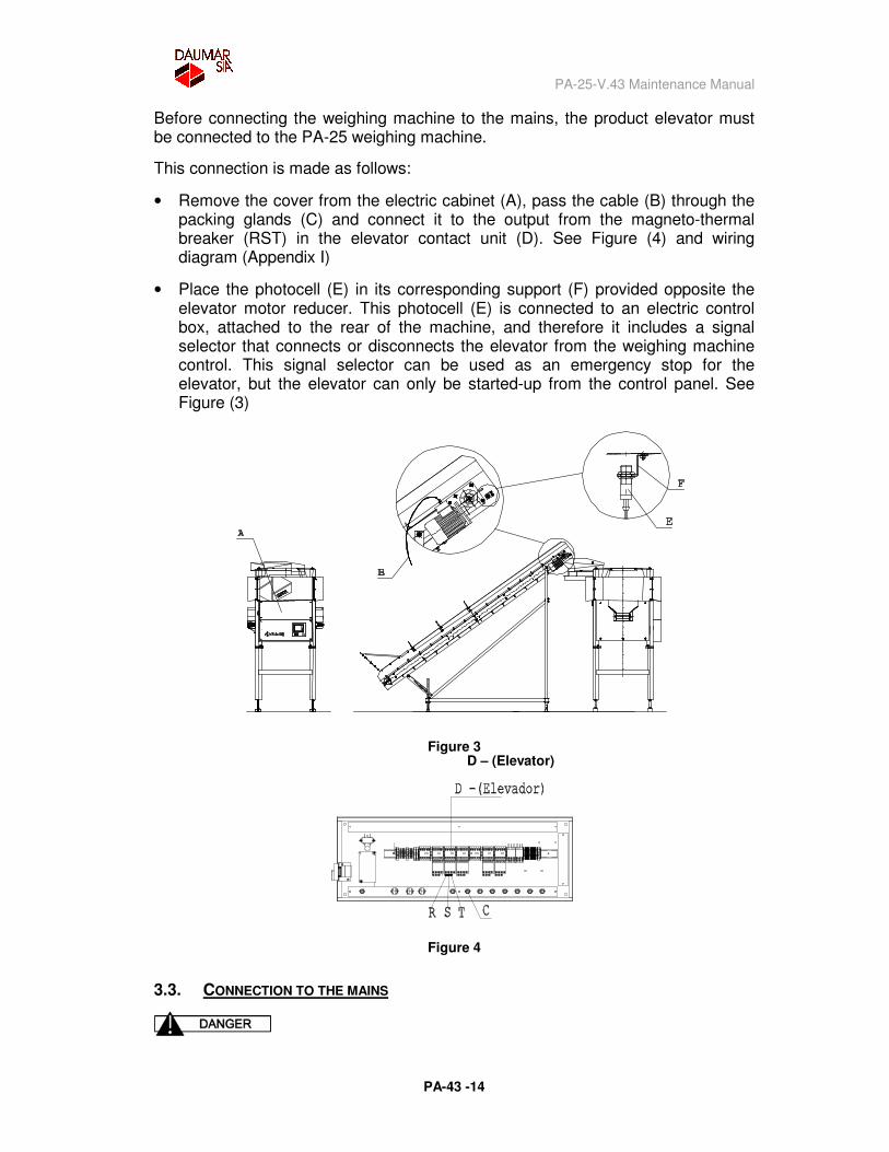
Before connecting the weighing machine to the mains, the product elevator must be connected to the PA-25 weighing machine.
This connection is made as follows:
• Remove the cover from the electric cabinet (A), pass the cable (B) through the packing glands (C) and connect it to the output from the magneto-thermal breaker (RST) in the elevator contact unit (D). See Figure (4) and wiring diagram (Appendix I)
• Place the photocell (E) in its corresponding support (F) provided opposite the elevator motor reducer. This photocell (E) is connected to an electric control box, attached to the rear of the machine, and therefore it includes a signal selector that connects or disconnects the elevator from the weighing machine control. This signal selector can be used as an emergency stop for the elevator, but the elevator can only be started-up from the control panel. See Figure (3)
Figure 3 D – (Elevator)
Figure 4
3.3. CONNECTION TO THE MAINS
PA-25-V.43 Maintenance Manual
PA-43 -15
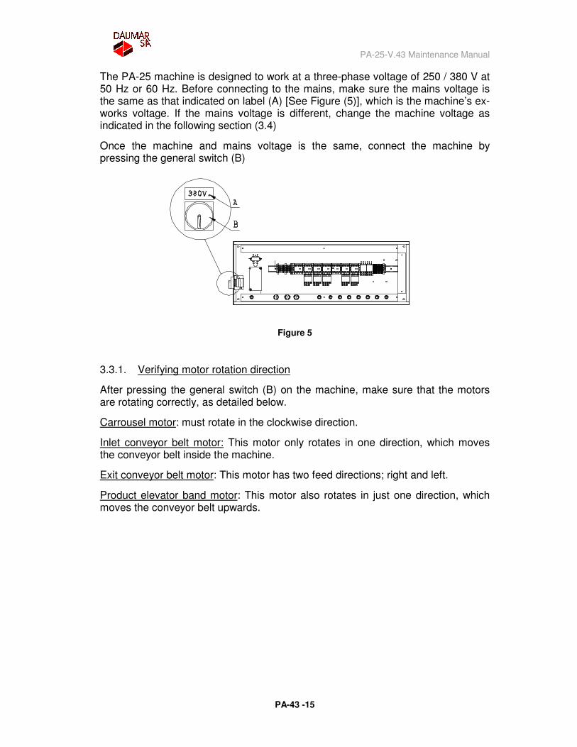
The PA-25 machine is designed to work at a three-phase voltage of 250 / 380 V at 50 Hz or 60 Hz. Before connecting to the mains, make sure the mains voltage is the same as that indicated on label (A) [See Figure (5)], which is the machine’s ex-works voltage. If the mains voltage is different, change the machine voltage as indicated in the following section (3.4)
Once the machine and mains voltage is the same, connect the machine by pressing the general switch (B)
Figure 5
3.3.1. Verifying motor rotation direction
After pressing the general switch (B) on the machine, make sure that the motors are rotating correctly, as detailed below.
Carrousel motor: must rotate in the clockwise direction.
Inlet conveyor belt motor: This motor only rotates in one direction, which moves the conveyor belt inside the machine.
Exit conveyor belt motor: This motor has two feed directions; right and left.
Product elevator band motor: This motor also rotates in just one direction, which moves the conveyor belt upwards.
PA-25-V.43 Maintenance Manual
PA-43 -16
3.4. CHANGING THE VOLTAGE
The weighing machine’s control box voltage is 220 V, and therefore to change the voltage, only the following elements have to be handled:
� Mains connection cable
� Carrousel motor
� Exit conveyor motor
� Product elevator motor
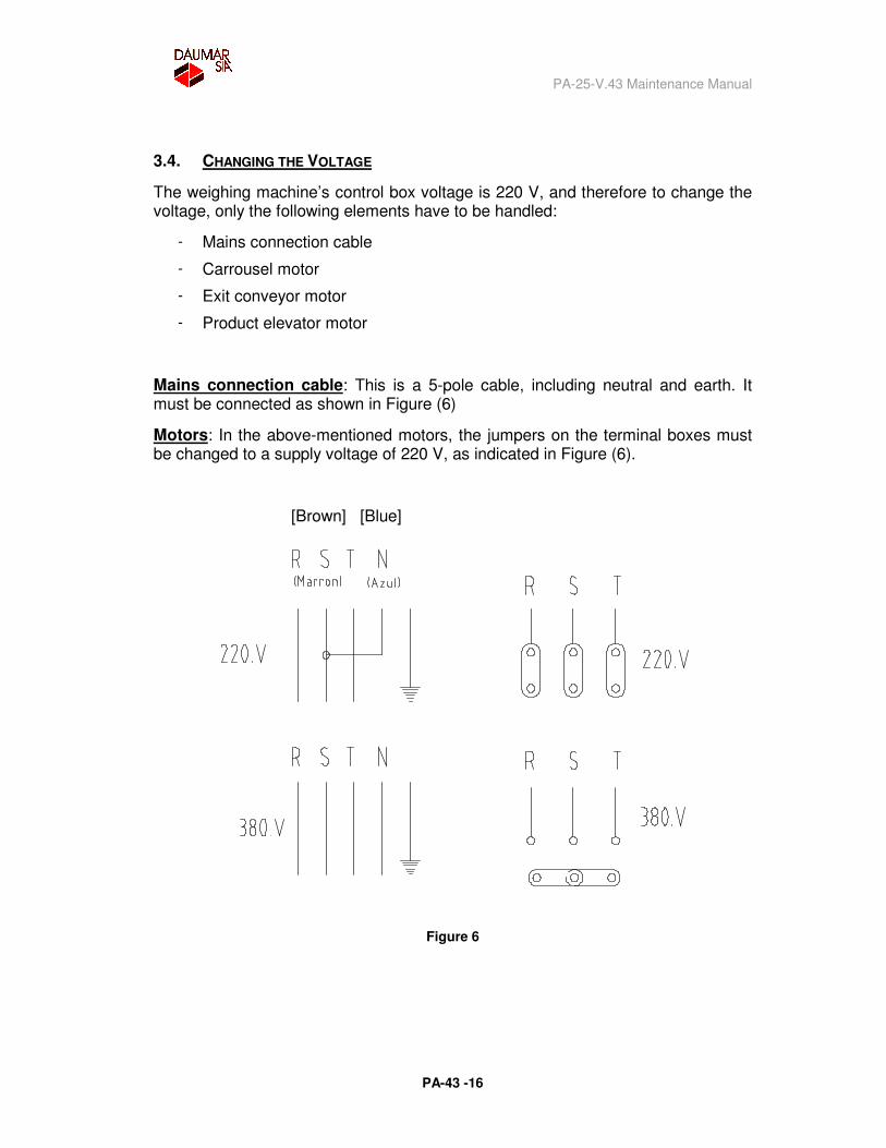
Mains connection cable: This is a 5-pole cable, including neutral and earth. It must be connected as shown in Figure (6)
Motors: In the above-mentioned motors, the jumpers on the terminal boxes must be changed to a supply voltage of 220 V, as indicated in Figure (6).
[Brown] [Blue]
Figure 6
PA-25-V.43 Maintenance Manual
PA-43 -17
3.5. CONTROLS
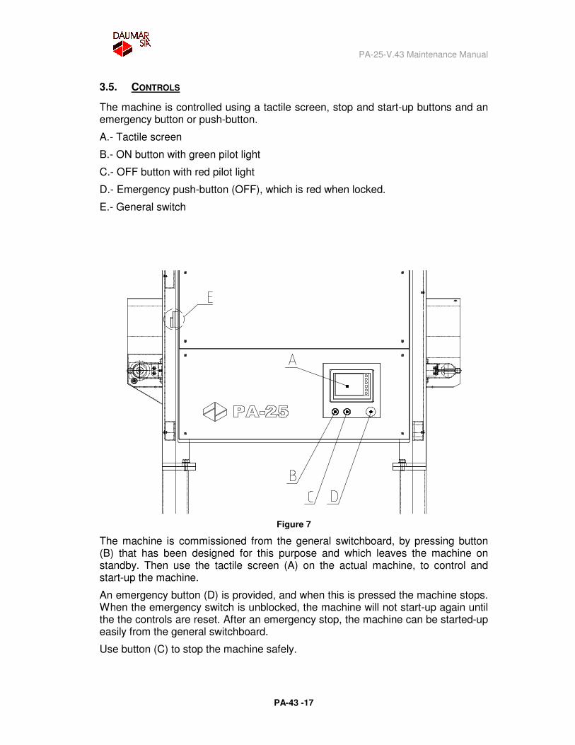
The machine is controlled using a tactile screen, stop and start-up buttons and an emergency button or push-button.
A.- Tactile screen
B.- ON button with green pilot light
C.- OFF button with red pilot light
D.- Emergency push-button (OFF), which is red when locked.
E.- General switch
Figure 7
The machine is commissioned from the general switchboard, by pressing button (B) that has been designed for this purpose and which leaves the machine on standby. Then use the tactile screen (A) on the actual machine, to control and start-up the machine.
An emergency button (D) is provided, and when this is pressed the machine stops. When the emergency switch is unblocked, the machine will not start-up again until the the controls are reset. After an emergency stop, the machine can be started-up easily from the general switchboard.
Use button (C) to stop the machine safely.
PA-25-V.43 Maintenance Manual
PA-43 -18
If the power supply is interrupted, the machine will stop and, when the power is restored, machine operation will not release, even though the indicators are working, until a new order is given.
A fault in the control circuit cannot cause the machine to start-up unexpectedly or prevent a manually controlled emergency stop.
PA-25-V.43 Maintenance Manual
PA-43 -19
4. CONNECTION TO PACKING MACHINES AND FEEDERS
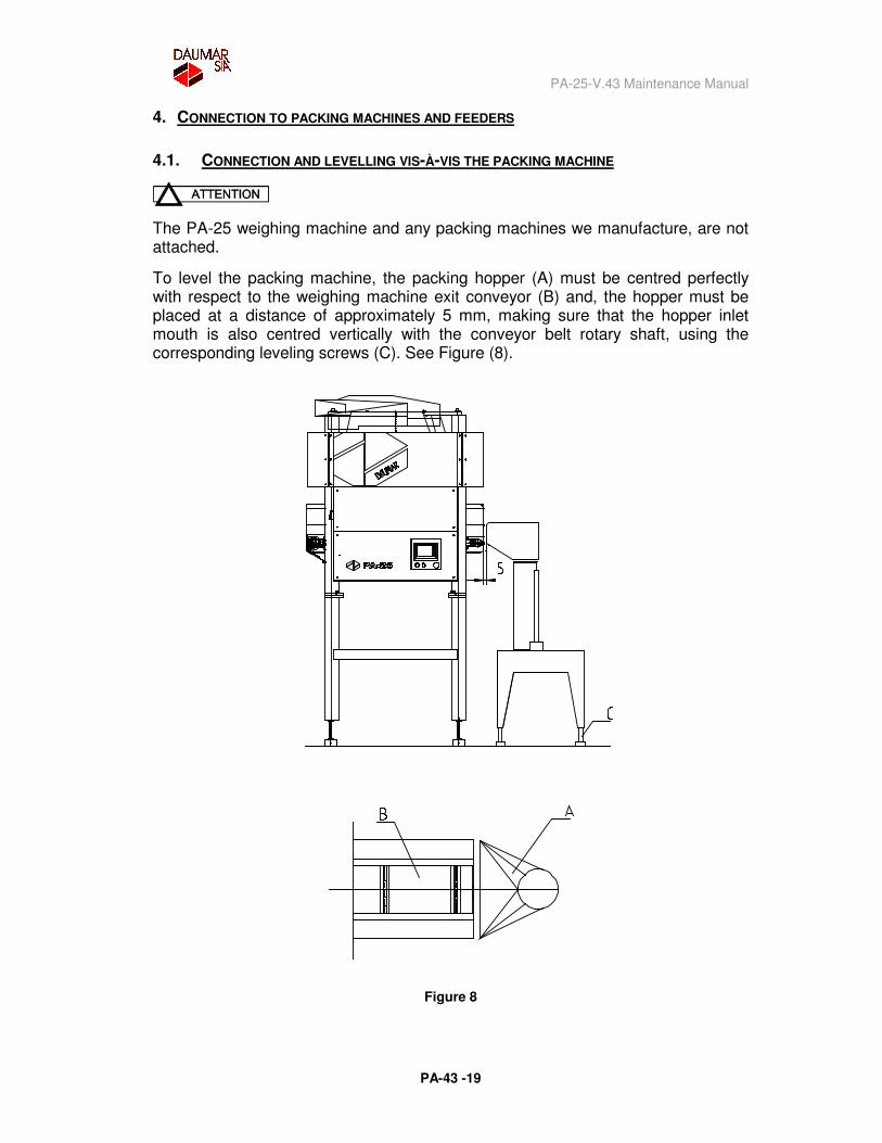
4.1. CONNECTION AND LEVELLING VIS-À-VIS THE PACKING MACHINE
The PA-25 weighing machine and any packing machines we manufacture, are not attached.
To level the packing machine, the packing hopper (A) must be centred perfectly with respect to the weighing machine exit conveyor (B) and, the hopper must be placed at a distance of approximately 5 mm, making sure that the hopper inlet mouth is also centred vertically with the conveyor belt rotary shaft, using the corresponding leveling screws (C). See Figure (8).
Figure 8
PA-25-V.43 Maintenance Manual
PA-43 -20
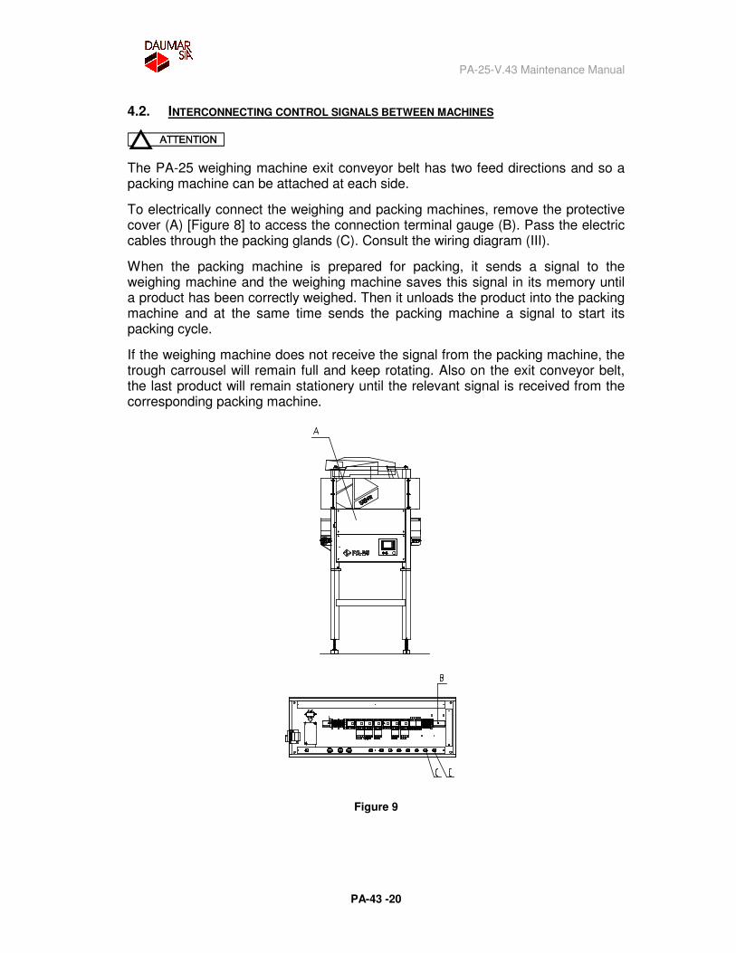
4.2. INTERCONNECTING CONTROL SIGNALS BETWEEN MACHINES
The PA-25 weighing machine exit conveyor belt has two feed directions and so a packing machine can be attached at each side.
To electrically connect the weighing and packing machines, remove the protective cover (A) [Figure 8] to access the connection terminal gauge (B). Pass the electric cables through the packing glands (C). Consult the wiring diagram (III).
When the packing machine is prepared for packing, it sends a signal to the weighing machine and the weighing machine saves this signal in its memory until a product has been correctly weighed. Then it unloads the product into the packing machine and at the same time sends the packing machine a signal to start its packing cycle.
If the weighing machine does not receive the signal from the packing machine, the trough carrousel will remain full and keep rotating. Also on the exit conveyor belt, the last product will remain stationery until the relevant signal is received from the corresponding packing machine.
Figure 9
PA-25-V.43 Maintenance Manual
PA-43 -21
4.3. CONNECTION TO THE POWER SUPPLY
As mentioned in the sections concerning characteristics and the description of the machine, the PA-25 weighing machine has an independent auxiliary unit which is the elevator conveyor, and any feeding system can be connected to this unit’s hopper, such as return belts, distribution belts, feeding tanks, direct feeders, etc.
To facilitate all these connections, the height of the elevator conveyor hopper is adjustable. Also, optional accessories are provided, which are detailed below:
PA-25-V.43 Maintenance Manual
PA-43 -22
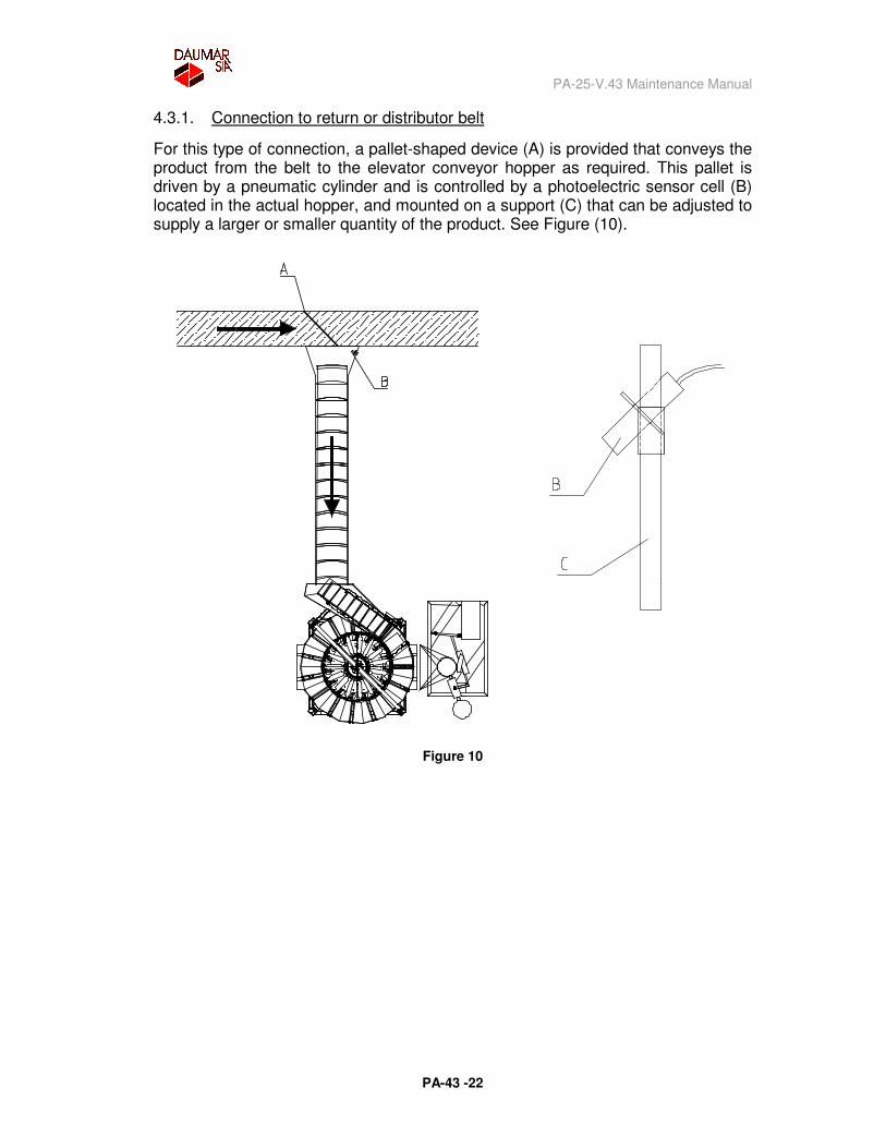
4.3.1. Connection to return or distributor belt
For this type of connection, a pallet-shaped device (A) is provided that conveys the product from the belt to the elevator conveyor hopper as required. This pallet is driven by a pneumatic cylinder and is controlled by a photoelectric sensor cell (B) located in the actual hopper, and mounted on a support (C) that can be adjusted to supply a larger or smaller quantity of the product. See Figure (10).
Figure 10
PA-25-V.43 Maintenance Manual
PA-43 -23
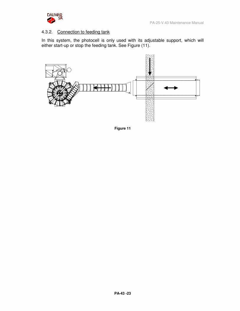
4.3.2. Connection to feeding tank
In this system, the photocell is only used with its adjustable support, which will either start-up or stop the feeding tank. See Figure (11).
Figure 11
PA-25-V.43 Maintenance Manual
PA-43 -24
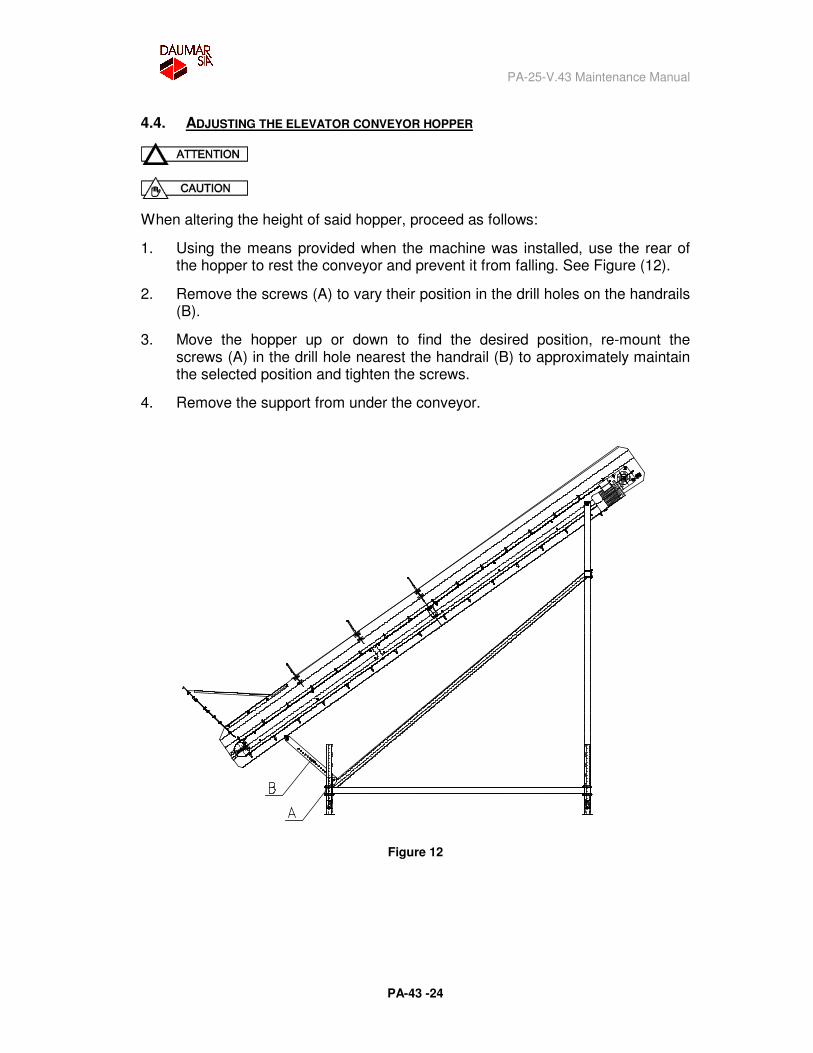
4.4. ADJUSTING THE ELEVATOR CONVEYOR HOPPER
When altering the height of said hopper, proceed as follows:
1. Using the means provided when the machine was installed, use the rear of the hopper to rest the conveyor and prevent it from falling. See Figure (12).
2. Remove the screws (A) to vary their position in the drill holes on the handrails (B).
3. Move the hopper up or down to find the desired position, re-mount the screws (A) in the drill hole nearest the handrail (B) to approximately maintain the selected position and tighten the screws.
4. Remove the support from under the conveyor.
Figure 12
PA-25-V.43 Maintenance Manual
PA-43 -25
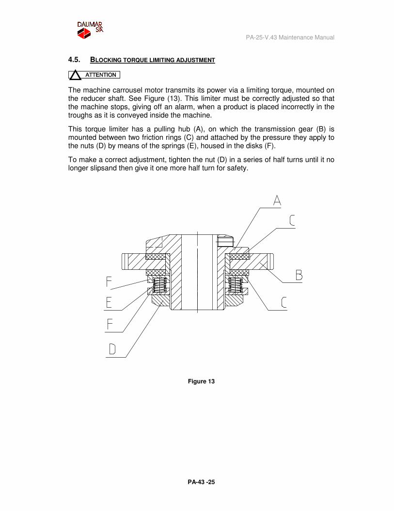
4.5. BLOCKING TORQUE LIMITING ADJUSTMENT
The machine carrousel motor transmits its power via a limiting torque, mounted on the reducer shaft. See Figure (13). This limiter must be correctly adjusted so that the machine stops, giving off an alarm, when a product is placed incorrectly in the troughs as it is conveyed inside the machine.
This torque limiter has a pulling hub (A), on which the transmission gear (B) is mounted between two friction rings (C) and attached by the pressure they apply to the nuts (D) by means of the springs (E), housed in the disks (F).
To make a correct adjustment, tighten the nut (D) in a series of half turns until it no longer slipsand then give it one more half turn for safety.
Figure 13
PA-25-V.43 Maintenance Manual
PA-43 -26
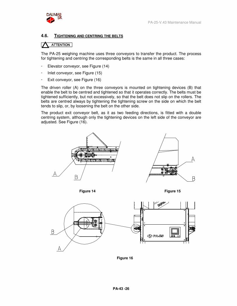
4.6. TIGHTENING AND CENTRING THE BELTS
The PA-25 weighing machine uses three conveyors to transfer the product. The process for tightening and centring the corresponding belts is the same in all three cases:
� Elevator conveyor, see Figure (14)
� Inlet conveyor, see Figure (15)
� Exit conveyor, see Figure (16)
The driven roller (A) on the three conveyors is mounted on tightening devices (B) that enable the belt to be centred and tightened so that it operates correctly. The belts must be tightened sufficiently, but not excessively, so that the belt does not slip on the rollers. The belts are centred always by tightening the tightening screw on the side on which the belt tends to slip, or, by loosening the belt on the other side.
The product exit conveyor belt, as it as two feeding directions, is fitted with a double centring system, although only the tightening devices on the left side of the conveyor are adjusted. See Figure (16).
Figure 14
Figure 15
Figure 16
PA-25-V.43 Maintenance Manual
PA-43 -27
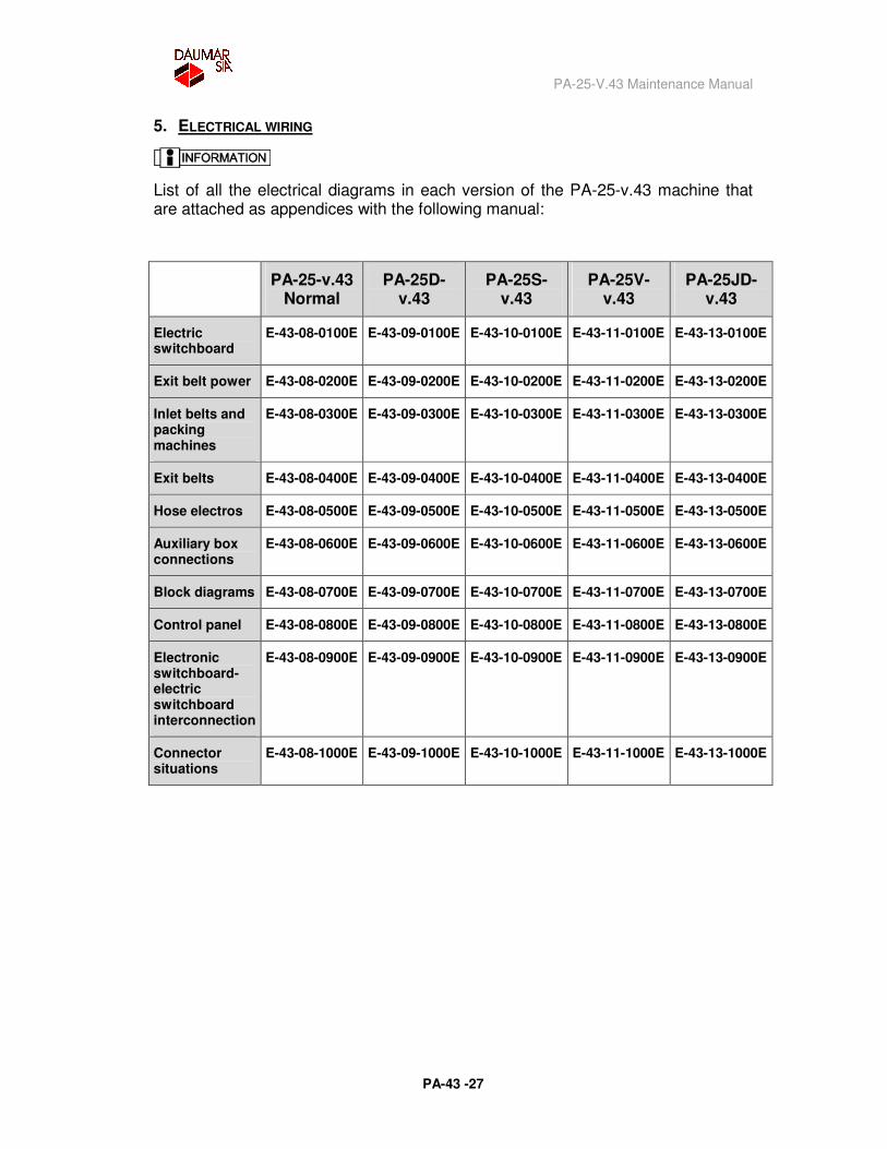
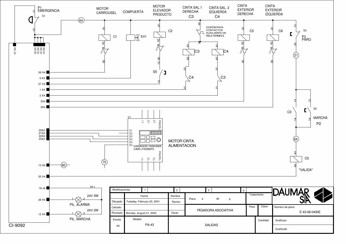
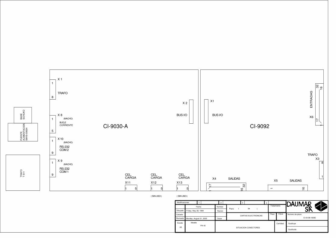
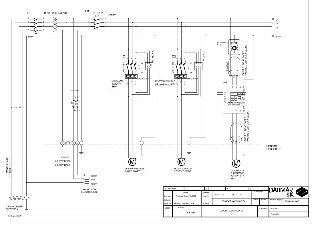
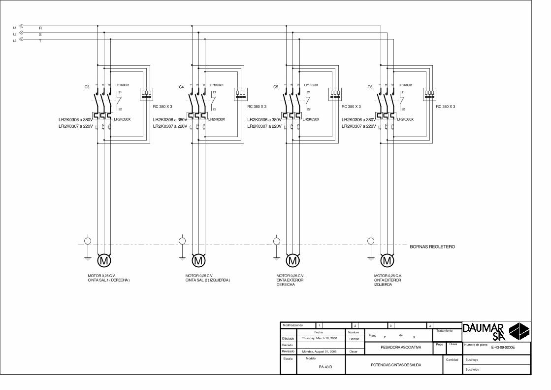
5. ELECTRICAL WIRING
List of all the electrical diagrams in each version of the PA-25-v.43 machine that are attached as appendices with the following manual:
PA-25-v.43 Normal
PA-25D-v.43
PA-25S-v.43
PA-25V-v.43
PA-25JD-v.43
Electric switchboard
E-43-08-0100E E-43-09-0100E E-43-10-0100E E-43-11-0100E E-43-13-0100E
Exit belt power E-43-08-0200E E-43-09-0200E E-43-10-0200E E-43-11-0200E E-43-13-0200E
Inlet belts and packing machines
E-43-08-0300E E-43-09-0300E E-43-10-0300E E-43-11-0300E E-43-13-0300E
Exit belts E-43-08-0400E E-43-09-0400E E-43-10-0400E E-43-11-0400E E-43-13-0400E
Hose electros E-43-08-0500E E-43-09-0500E E-43-10-0500E E-43-11-0500E E-43-13-0500E
Auxiliary box connections
E-43-08-0600E E-43-09-0600E E-43-10-0600E E-43-11-0600E E-43-13-0600E
Block diagrams E-43-08-0700E E-43-09-0700E E-43-10-0700E E-43-11-0700E E-43-13-0700E
Control panel E-43-08-0800E E-43-09-0800E E-43-10-0800E E-43-11-0800E E-43-13-0800E
Electronic switchboard-electric switchboard interconnection
E-43-08-0900E E-43-09-0900E E-43-10-0900E E-43-11-0900E E-43-13-0900E
Connector situations
E-43-08-1000E E-43-09-1000E E-43-10-1000E E-43-11-1000E E-43-13-1000E

PA-43 NORMAL

RC
380
X 3
1-3 380V LINEA
RC
380
X 3
TO-2-8293-E+SVB
A TOMA DE REDELECTRICA
2-3 230V LINEA
MA
NG
UE
RA
DE
5x2.
5
N
BORNASREGLETERO
TRIFAS. 380V
5
L3
3
VALIDA
1
L1
230V A CUADROELECTRONICO
MOTOR ELEVADOR0,75 C.V. 0,55 KW
4
L2
2
MOTOR CINTAALIMENTADOR0,25 C.V. 0,18KW
PUENTE
MOTOR CARRUOSEL0,5 C.V. 0,36 KW
LR 2K 0306 a380V y 220V LR 2K 0308 a 380V
N
L1
L2
L3
LR2K0310 a 220V
CIMR-J7AZB0P2
FILTRO REDFA-6Z
Monday, August 01, 2005PESADORA ASOCIATIVA
Thursday, March 16, 2000
PA-43
E-43-08-0100E
Ramón
Oscar
CUADRO ELECTRICO 1/2
91
Escala
Plano deDibujado
Calcado
Revisado
Fecha Nombre
Modelo
Sustituido
Sustituye
Tratamiento
Peso Clave
1 2 3 4
Cantidad
Modificaciones
Numero de plano
N
TIERRA
L2 L3L1
L2
L3
TIERRA
L1
LR 2K.030X
13
14
C2
LP1K
091
0BD
1 3 5
2T1
4T2
6T3
LR 2K.030X
13
14
C1
LP1K
061
0BD
1 3 5
2T1
4T2
6T3
M M
F2
5A
F1
5A
LP1K0910C0
1
3
5
2
4
6
M
S1
1
3
5
2
4
6
7 8
U45
VARIADOR YASKAWA
L1 L2 L3
T1
T2
T3
TIE
RR
A
S2S3S4S5SC
S1 TIE
RR
AC
AB
LES
LIN
EA
S F
AS
ES
PA
SA
DO
S C
ON
UN
A V
UE
LTA
CA
BLE
S L
INE
AS
FA
SE
SP
AS
AD
OS
CO
N U
NA
VU
ELT
A
KIT
AG
AW
A
0 (230V)
230V
TIERRA
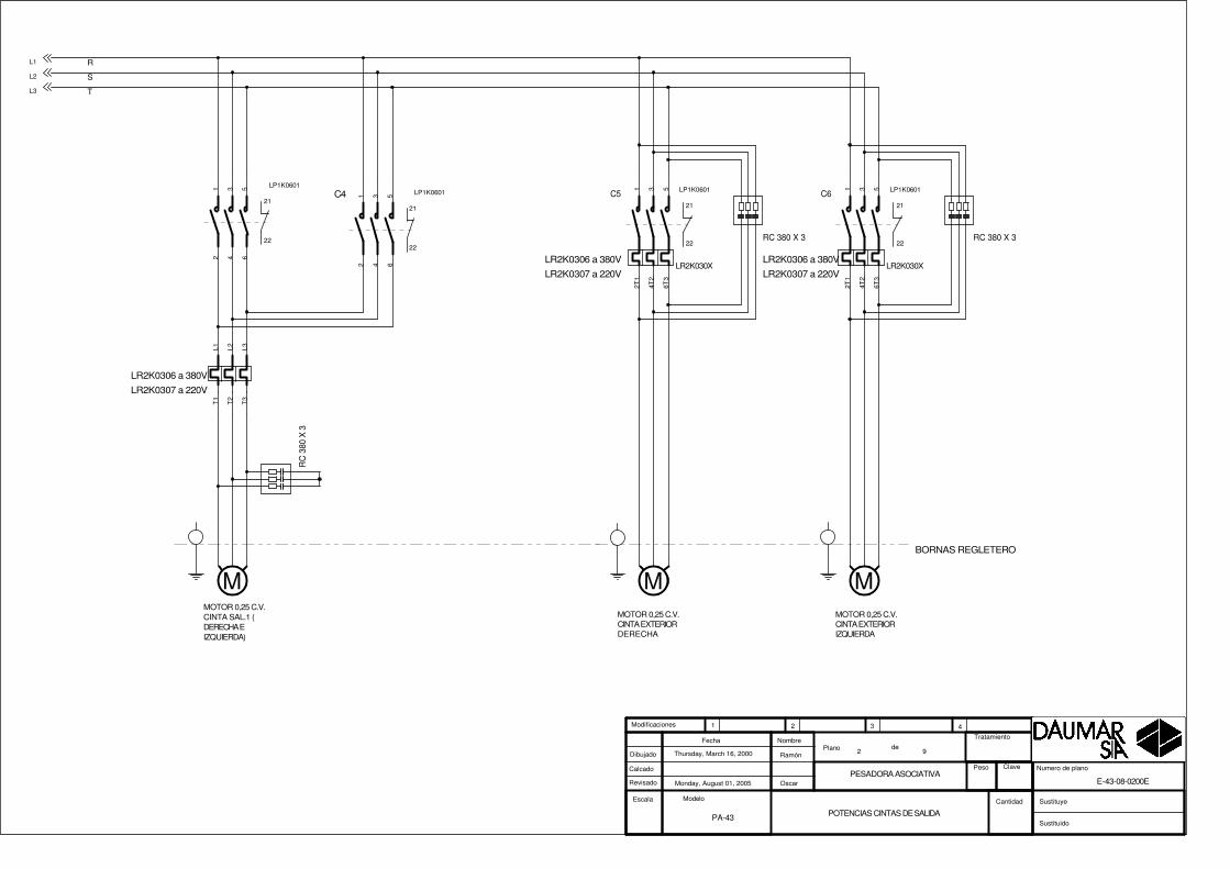
MOTOR 0,25 C.V.CINTA SAL.1 (DERECHA EIZQUIERDA)
R
T
S
LR2K0306 a 380V
MOTOR 0,25 C.V.CINTA EXTERIORDERECHA
MOTOR 0,25 C.V.CINTA EXTERIORIZQUIERDA
BORNAS REGLETERO
RC 380 X 3RC 380 X 3
C4
RC
380
X 3
LR2K0306 a 380V LR2K0306 a 380VLR2K0307 a 220V LR2K0307 a 220V
LR2K0307 a 220V
Monday, August 01, 2005PESADORA ASOCIATIVA
Thursday, March 16, 2000
PA-43
E-43-08-0200E
Ramón
Oscar
POTENCIAS CINTAS DE SALIDA
92
Escala
Plano deDibujado
Calcado
Revisado
Fecha Nombre
Modelo
Sustituido
Sustituye
Tratamiento
Peso Clave
1 2 3 4
Cantidad
Modificaciones
Numero de plano
L1
L2
L3
M
21
22
LP1K06011 3 5
2 4 6
M
LR2K030X
21
22
C5 LP1K06011 3 5
2T1
4T2
6T3
M
LR2K030X
21
22
C6 LP1K06011 3 5
2T1
4T2
6T3
L1T
1
L2T
2
L3T
3
21
22
LP1K06011 3 5
2 4 6
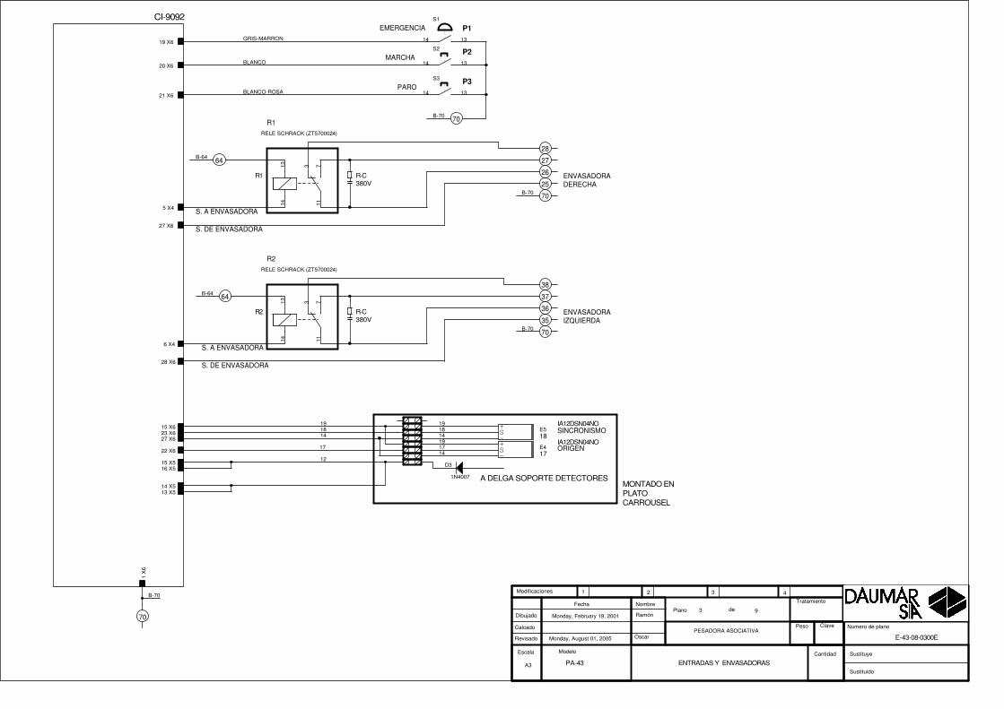
S. DE ENVASADORA
S. A ENVASADORA
EMERGENCIA
MARCHA
PARO
P1
P2
P3
ENVASADORADERECHA
R-C380V
S. DE ENVASADORA
S. A ENVASADORA
R-C380V
ENVASADORAIZQUIERDA
26
27
70
25
36
37
70
35
28
38
70
70
64
64
SINCRONISMO
ORIGEN
A DELGA SOPORTE DETECTORESMONTADO ENPLATOCARROUSEL
IA12DSN04NO
IA12DSN04NO
17
18
A3
Monday, August 01, 2005
ENTRADAS Y ENVASADORAS
Monday, February 19, 2001
PA-43
E-43-08-0300E
Ramón
OscarPESADORA ASOCIATIVA
93
Escala
Plano deDibujado
Calcado
Revisado
Fecha Nombre
Modelo
Sustituido
Sustituye
Tratamiento
Peso Clave
1 2 3 4
Cantidad
Modificaciones
Numero de plano
CI-9092
19 X6
20 X6
21 X6
27 X6
5 X4
1 X
6
6 X4
28 X6
15 X623 X627 X6
22 X6
15 X516 X5
14 X513 X5
B-70
B-70
B-70
B-64
BLANCO
B-70
BLANCO-ROSA
GRIS-MARRON
B-64
14
1419
1918
17
19
1418
17
12D3
1N4007
+
-S E5
+
-S E4
R2RELE SCHRACK (ZT5700024)
R2
1314 11
3 7
S1
1314
S2
1314
S3
1314
R1RELE SCHRACK (ZT5700024)
R1
1314 11
3 7
MARCHA
PARO
"VALIDA"
MOTORCARROUSEL
PIL. MARCHA
P3
PIL. ALARMA
P2
COMPUERTA
64
21
MOTORELEVADORPRODUCTO
CINTA SAL.1DERECHA
CINTA SAL. 2IZQUIERDA
24V 3W
CINTAEXTERIORDERECHA
CINTAEXTERIORIZQUIERDA
MOTOR CINTAALIMENTACION
64
P1EMERGENCIA
80
24V 3W
70
C4 C3
C3 C4
C4C3
(CORTAR PATACONTACTOSAUXILIARES DERELE TERMICO)
CIMR-J7AZB0P2
A4
Monday, August 01, 2005
SALIDAS
Tuesday, February 20, 2001
PA-43
E-43-08-0400E
Ramón
OscarPESADORA ASOCIATIVA
94
Escala
Plano deDibujado
Calcado
Revisado
Fecha Nombre
Modelo
Sustituido
Sustituye
Tratamiento
Peso Clave
1 2 3 4
Cantidad
Modificaciones
Numero de plano
CI-9092
12 X4
26 X4
9 X4
25 X4
27 X4
28 X4
31 X
4
13 X
4
1 X4
2 X4
20X421X422X423X4
3X4
4X4
16 x6
14 X
415
X4
16 X
4
13 X6
24 v
S3
2122
C0
A1
A2
S2
1314
1 2
S1
2122
C0
1314
1 2
A2
96
C2
A1
95
EV1
A2
96
C1
A1
95
V1
VARIADOR YASKAWAL1 L2 L3
T1
T2
T3
TIE
RR
A
S2S3S4S5SC
S1 TIE
RR
A
S5
1314
A2
96
C5
A1
95
A2
96
C6
A1
95
2122
2122
9596
A1
A2
A1
A2

(COMUN 70V)
MANGUERA ELECTROIMANES
A4
Monday, August 01, 2005
MANGUERA ELECTROS
Thursday, October 11, 2001
PA-43
E-43-08-0500E
Ramón
OscarPESADORA ASOCIATIVA
95
Escala
Plano deDibujado
Calcado
Revisado
Fecha Nombre
Modelo
Sustituido
Sustituye
Tratamiento
Peso Clave
1 2 3 4
Cantidad
Modificaciones
Numero de plano
CI-9092
13 X
5
14 X
5
15 X
5
16 X
51 X5
2 X5
3 X5
4 X5
5 X5
6 X5
7 X5
8 X5
9 X5
10 X5
6
1
5
8
3
4
7
2
10
9
E1
A1
A2
E2
A1
A2
E3
A1
A2
E5
A1
A2
E6
A1
A2
E7
A1
A2
E4
A1
A2
E10
A1
A2
E8
A1
A2
E9
A1
A2

PRODUCTO ENCINTAALIMENTACION
CUBETA ABIERTA
PRODUCTO ENELEVADOR
70
1
2
3
7080
80
7
95 C2
COMPUERTA
SELECTORELEVADORON/OFF
CAJA ELECTRICAEN BANCADA
PA18CSD04NASA
PA18CSD04NASA
1
2
3
64
8
94X4
3X4
EV 1
A4
Monday, August 01, 2005
CONEXIONES CAJA AUXILIAR
Tuesday, September 07, 2004
PA-43
E-43-08-0600E
Ramón
OscarPESADORA ASOCIATIVA
96
Escala
Plano deDibujado
Calcado
Revisado
Fecha Nombre
Modelo
Sustituido
Sustituye
Tratamiento
Peso Clave
1 2 3 4
Cantidad
Modificaciones
Numero de plano
CI-9092
26 X6
25 X6
24 X6
18 X6
16 X6
27 X4
9 X4
5
8
9
1
4
3
2
10
11
1314
D1
51V 4W
+
-S E6 IA30DSN15NO
FOT14
SL
+
-
E7
FOT14
SL
+
-
E8

PANTALLA TACTIL
BASE( 230 V AC)
ALIMENTACIONPANTALLA TACTIL
A FUSIBLES ENCUADROPOTENCIA
COM 2DB25
+ 24GND
TIERRA
A3
Monday, August 01, 2005
ESQUEMA BLOQUES
Monday, February 19, 2001
PA-43
E-43-08-0700E
Ramón
OscarPESADORA ASOCIATIVA
97
Escala
Plano deDibujado
Calcado
Revisado
Fecha Nombre
Modelo
Sustituido
Sustituye
Tratamiento
Peso Clave
1 2 3 4
Cantidad
Modificaciones
Numero de plano
verde 7amarillo 3
gris 2
ROJO-ROSA
AZUL-NEGRO
45
CELULA DE CARGA
azul+verdenegro+amarillo
blancorojo
malla
v+v-s-s+blindaje
CA
BLE
S LIN
EA
S FA
SE
SP
AS
AD
OS
CO
N U
NA
VU
ELTA
KITAGAWA
X2BUS I/O
X11CELULA DE CARGA
X1 TRANSFORMADOR
X7TECLADO
X6 DISPLAY
CI-9024C
CARTA MICROPROCESADOR
X9COM 1
DIP 34
POSTE 10
DIP 20
X10COM 2
WEID 5
WEID 5
WEID 8
X8BUCLE CORR.
CI-9030A
x6.1x6.2x6.3x6.4x6.5x6.6x6.7x6.8x6.9
x6.10x6.11x6.12x6.13x6.14
x2.1x2.2x2.3x2.4x2.5x2.6x2.7x2.8x2.9x2.10x2.11x2.12x2.13x2.14x2.15x2.16x2.17x2.18x2.19x2.20x2.21x2.22x2.23x2.24x2.25x2.26x2.27x2.28x2.29x2.30x2.31x2.32x2.33x2.34
x6.15x6.16x6.17x6.18x6.19x6.20
x7.1x7.2x7.3x7.4x7.5x7.6x7.7x7.8x7.9
x7.10x7.11x7.12x7.13x7.14x7.15
x1.1x1.2x1.3x1.4x1.5x1.6x1.7x1.8
X11
.1X
11.2
X11
.3X
11.4
X11
.5
X9.
2X
9.3
X9.
5X
9.7
X9.
8
x10.
2X
10.3
X10
.5X
10.7
X10
.8
X8.1X8.2X8.3X8.4X8.5
vccvccncncncd0d1d2d3d4d5d6d7ba1
VccVccba8ba7ba6ba5ba4ba3ba2ba1int3int2
s1s2s3s4
vmas5s6e
basdtackwatch
r/wd7d6d5d4d3d2d1d0
gndgnd
r/wecsrstgndgnd
in1in2in3in4q1q2q3q4q5q6q7q8ncgndvcc
11a0a11a20h0h11rs0rsnc
0V S-
S+
-V +V
RX
TX
GN
DR
TS
CT
S
RX
TX
GN
DR
TS
CT
S
+B0 BRxTx
N.C.
CONECTOR X1BUS I/O
CONECTOR X3TRANSFORMADOR
DIP 34
WEID 2 X 16
WEID 2 X 16
WEID 1 X 8WEID 1 X 16
CI-9092
x1.1x1.2x1.3x1.4x1.5x1.6x1.7x1.8x1.9
x1.10x1.11x1.12x1.13x1.14x1.15x1.16x1.17x1.18x1.19x1.20x1.21x1.22x1.23x1.24x1.25x1.26x1.27x1.28x1.29x1.30x1.31x1.32x1.33x1.34
X3.1X3.2X3.3X3.4X3.5X3.6X3.7X3.8
X4[1..32]
X6[1..32]
X5[1..16]
VccVccba8ba7ba6ba5ba4ba3ba2ba1int3int2s1s2s3s4vmas5s6ebasdtackwatchr/wd7d6d5d4d3d2d1d0gndgnd
24 P0 P19 SA036 SA024 OP0 OP
SALIDAS[1..32]
ENTRADAS[1..32]
SAL. OVER POWER[1..12]
FE
RR
ITA
KIT
AG
AW
A
����
����
��
���
��
�����
��
��
T-511
0
230
11
0
11
245
0
20
28
0
20
0
0
11
200
0
36
0
19
FA-6Z
S8VS-03024
OMRON
NL GN
D-++ -
24 O
P0
OP
19 S
A0
SA
36 S
A1
0 36
SA
1
24 P
0 P
24 OP
0 OP
19 SA
0 SA
36 SA1
0 SA1
24 P
0 P
0 (230V)
230V
TIERRA

CABLEADO ACUADROELECTRONICO
EMERGENCIA
PULSADORTIPO SETA
PARO
EAO DIFUSORVERDE
PILOTO ( MARCHA )LAM. 24V
MARCHA
EAO DIFUSORROJO
FICHADB25M
a (X9) U1
PILOTO (ALARMA)LAM. 24V
FICHADB9 H
CABLEADO ACUADROELECTRICO
A4
Monday, August 01, 2005
CUADRO DE MANDO
Thursday, July 27, 2000
PA-43
E-43-08-0800E
Ramón
OscarPESADORA ASOCIATIVA
98
Escala
Plano deDibujado
Calcado
Revisado
Fecha Nombre
Modelo
Sustituido
Sustituye
Tratamiento
Peso Clave
1 2 3 4
Cantidad
Modificaciones
Numero de plano
GRIS2
31 X4
21X6
19X6
19x6
28X4
60
17X6
21x6
VERDE5
B-21 21
28x4
16 X4
21 646470
12X420X6
12x4
20x6
(A1 C0)
RX
GN
D
AMARILLO3
TX
24V PANTALLAGND PANTALLA
16 X6
16x6
70 70
21222122
P1
1314
P2
1314
P4
1314
1314
���� ����
DB9 DB25
FUJI UG-22-HI-CS
12
2 3 85 7 2 3 4 5 76 20
+24VGND
Rx
Tx
CT
S
GN
DR
TS
Tx
Rx
RT
SC
TS
GN
DD
SR
DT
R

MANGUERA INTERCONEXIONCUADRO ELECTRICO A CUADRO ELECTRONICO a CUADRO
ELECTRONICOA CUADROELECTRICO
A4
Monday, August 01, 2005
Interconexion C.electronico - C. electrico
Thursday, July 27, 2000
PA-43
E-43-08-0900E
Ramón
OscarPESADORA ASOCIATIVA
99
Escala
Plano deDibujado
Calcado
Revisado
Fecha Nombre
Modelo
Sustituido
Sustituye
Tratamiento
Peso Clave
1 2 3 4
Cantidad
Modificaciones
Numero de plano
1 6 x4
9 27X610 13 X6
14 4 X4
8 5X4
15 20 X4
11 1 X412 2 X4
4 64 (14X4)
13 3 X4
3
7 26X4
5 70 (1X6)6 25X4
2 28 X61A2 RELE 2
9BORNA 25 (ENVASADORA)10B-80
14A2 C6
8A2 RELE 1
15S1 V1
11A2 C312A2 C4
4B-64
13A2 C5
3
7A2 C1 (95 TERMICO)
5B-706A2 C0
2B-35
16 21 X417 22 X418 23 X4
16S3 V117S4 V118S5 V1
X4
X6
X3
X1
SALIDAS
EN
TR
AD
AS
TRAFO
BUS I/O
117
1632
171
1632
1
8
X 2
X 8
X11
X 1
TRAFO
RS-232COM 1
CEL.CARGA
CEL.CARGA
BUS I/O1
5
1
8
1 5
CI-9030-A CI-9092
X5 SALIDAS
161
X 9
1
9
X 10
1
9
X12
1 5
X13
1 5
CEL.CARGA
RS-232COM 2
( SIN USO ) ( SIN USO )
TR
AF
OT
-511
BA
SE
SC
HU
KO
BUCLECORRIENTE
(MACHO)
(MACHO)
(MACHO)
FU
EN
TE
ALI
ME
NT
AC
ION
S8V
S-0
3024
A3
Monday, August 01, 2005
SITUACION CONECTORES
Friday, May 28, 1999
PA-43
E-43-08-1000E
Ramón
Oscar
CARTAS ELECTRONICAS
11
Escala
Plano deDibujado
Calcado
Revisado
Fecha Nombre
Modelo
Sustituido
Sustituye
Tratamiento
Peso Clave
1 2 3 4
Cantidad
Modificaciones
Numero de plano

PA-43D
RC
380
X 3
1-3 380V LINEA
RC
380
X 3
TO-2-8293-E+SVB
A TOMA DE REDELECTRICA
2-3 230V LINEA
MA
NG
UE
RA
DE
5x2.
5
N
BORNASREGLETERO
TRIFAS. 380V
5
L3
3
VALIDA
1
L1
230V A CUADROELECTRONICO
MOTOR ELEVADOR0,75 C.V. 0,55 KW
4
L2
2
MOTOR CINTAALIMENTADOR0,25 C.V. 0,18KW
PUENTE
MOTOR CARRUOSEL0,5 C.V. 0,36 KW
LR2K0306a220V y380V
LR2K0308 a 380V
N
L1
L2
L3
LR2K0310 a 220V
CIMR-J7AZB0P2
FILTRO REDFA-6Z
Monday, August 01, 2005PESADORA ASOCIATIVA
Thursday, March 16, 2000
PA-43 D
E-43-09-0100E
Ramón
Guillem
CUADRO ELECTRICO 1/2
91
Escala
Plano deDibujado
Calcado
Revisado
Fecha Nombre
Modelo
Sustituido
Sustituye
Tratamiento
Peso Clave
1 2 3 4
Cantidad
Modificaciones
Numero de plano
N
TIERRA
L2 L3L1
L2
L3
TIERRA
L1
LR 2K.030X
13
14
C2
LP1K
091
0BD
1 3 5
2T1
4T2
6T3
LR 2K.030X
13
14
C1
LP1K
061
0BD
1 3 5
2T1
4T2
6T3
M M
F2
5A
F1
5A
LP1K0910C0
1
3
5
2
4
6
M
S1
1
3
5
2
4
6
7 8
U45
VARIADOR YASKAWA
L1 L2 L3
T1
T2
T3
TIE
RR
A
S2S3S4S5SC
S1 TIE
RR
AC
AB
LES
LIN
EA
S F
AS
ES
PA
SA
DO
S C
ON
UN
A V
UE
LTA
CA
BLE
S L
INE
AS
FA
SE
SP
AS
AD
OS
CO
N U
NA
VU
ELT
A
KIT
AG
AW
A
0 (230V)
230V
TIERRA
MOTOR 0,25 C.V.CINTA SAL.1 ( DERECHA )
MOTOR 0,25 C.V.CINTA SAL. 2 ( IZQUIERDA )
R
T
S
RC 380 X 3RC 380 X 3
LR2K0306 a 380V LR2K0306 a 380V
MOTOR 0,25 C.V.CINTA EXTERIORDERECHA
MOTOR 0,25 C.V.CINTA EXTERIORIZQUIERDA
BORNAS REGLETERO
RC 380 X 3RC 380 X 3
LR2K0306 a 380V LR2K0306 a 380VLR2K0307 a 220VLR2K0307 a 220V LR2K0307 a 220V LR2K0307 a 220V
Monday, August 01, 2005PESADORA ASOCIATIVA
Thursday, March 16, 2000
PA-43 D
E-43-09-0200E
Ramón
Oscar
POTENCIAS CINTAS DE SALIDA
92
Escala
Plano deDibujado
Calcado
Revisado
Fecha Nombre
Modelo
Sustituido
Sustituye
Tratamiento
Peso Clave
1 2 3 4
Cantidad
Modificaciones
Numero de plano
L1
L2
L3
M M M
LR2K030X
21
22
C5 LP1K06011 3 5
2T1
4T2
6T3
M
LR2K030X
21
22
C6 LP1K06011 3 5
2T1
4T2
6T3
LR2K030X
21
22
C3 LP1K06011 3 5
2T1
4T2
6T3
LR2K030X
21
22
C4 LP1K06011 3 5
2T1
4T2
6T3

S. DE ENVASADORA
S. A ENVASADORA
EMERGENCIA
MARCHA
PARO
P1
P2
P3
ENVASADORADERECHA
R-C380V
S. DE ENVASADORA
S. A ENVASADORA
R-C380V
ENVASADORAIZQUIERDA
26
27
70
25
36
37
70
35
28
38
70
70
64
64
SINCRONISMO
ORIGEN
A DELGA SOPORTE DETECTORESMONTADO ENPLATOCARROUSEL
IA12DSN04NO
IA12DSN04NO
17
18
A3
Monday, August 01, 2005
ENTRADAS Y ENVASADORAS
Monday, February 19, 2001
PA-43D
E-43-09-0300E
Ramón
OscarPESADORA ASOCIATIVA
93
Escala
Plano deDibujado
Calcado
Revisado
Fecha Nombre
Modelo
Sustituido
Sustituye
Tratamiento
Peso Clave
1 2 3 4
Cantidad
Modificaciones
Numero de plano
CI-9092
19 X6
20 X6
21 X6
27 X6
5 X4
1 X
6
6 X4
28 X6
15 X623 X627 X6
22 X6
15 X516 X5
14 X513 X5
B-70
B-70
B-70
B-64
BLANCO
B-70
BLANCO-ROSA
GRIS-MARRON
B-64
14
1419
1918
17
19
1418
17
12
R1RELE SCHRACK (ZT5700024)
R1
1314 11
3 7
S3
1314
+
-S E5
D3
1N4007
+
-S E4
R2RELE SCHRACK (ZT5700024)
R2
1314 11
3 7
S2
1314
S1
1314
MARCHA
PARO
"VALIDA"
MOTORCARROUSEL
PIL. MARCHA
P3
PIL. ALARMA
P2
COMPUERTA
64
21
MOTORELEVADORPRODUCTO
CINTA SAL.1DERECHA
CINTA SAL. 2IZQUIERDA
24V 3W
CINTAEXTERIORDERECHA
CINTAEXTERIORIZQUIERDA
MOTOR CINTAALIMENTACION
64
P1EMERGENCIA
80
24V 3W
70
CIMR-J7AZB0P2
A4
Monday, August 01, 2005
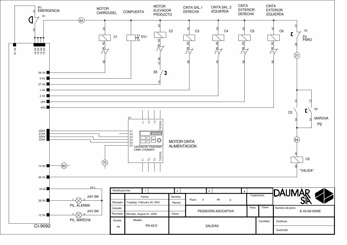
SALIDAS
Tuesday, February 20, 2001
PA-43 D
E-43-09-0400E
Ramón
OscarPESADORA ASOCIATIVA
94
Escala
Plano deDibujado
Calcado
Revisado
Fecha Nombre
Modelo
Sustituido
Sustituye
Tratamiento
Peso Clave
1 2 3 4
Cantidad
Modificaciones
Numero de plano
CI-9092
12 X4
26 X4
9 X4
25 X4
27 X4
28 X4
31 X
4
13 X
4
1 X4
2 X4
20X421X422X423X4
3X4
4X4
16 x6
14 X
415
X4
16 X
4
13 X6
24 v
C0
A1
A2
S3
2122
C0
1314
S1
2122
1 2
S2
1314
A2
96
C2
A1
95
1 2
A2
96
C1
A1
95
EV1
V1
VARIADOR YASKAWAL1 L2 L3
T1
T2
T3
TIE
RR
A
S2S3S4S5SC
S1 TIE
RR
A
S5
1314
A2
96
C5
A1
95
A2
96
C6
A1
95
A2
96
C3
A1
95
A2
96
C4
A1
95

(COMUN 70V)
MANGUERA ELECTROIMANES
A4
Monday, August 01, 2005
MANGUERA ELECTROS
Thursday, October 11, 2001
PA-43 D
E-43-09-0500E
Ramón
OscarPESADORA ASOCIATIVA
95
Escala
Plano deDibujado
Calcado
Revisado
Fecha Nombre
Modelo
Sustituido
Sustituye
Tratamiento
Peso Clave
1 2 3 4
Cantidad
Modificaciones
Numero de plano
CI-9092
13 X
5
14 X
5
15 X
5
16 X
51 X5
2 X5
3 X5
4 X5
5 X5
6 X5
7 X5
8 X5
9 X5
10 X5
6
1
5
8
3
4
7
2
10
9
E3
A1
A2
E2
A1
A2
E1
A1
A2
E4
A1
A2
E7
A1
A2
E6
A1
A2
E5
A1
A2
E9
A1
A2
E8
A1
A2
E10
A1
A2
PRODUCTO ENCINTAALIMENTACION
CUBETA ABIERTA
PRODUCTO ENELEVADOR
70
1
2
3
7080
80
7
95 C2
COMPUERTA
SELECTORELEVADORON/OFF
CAJA ELECTRICAEN BANCADA
PA18CSD04NASA
PA18CSD04NASA
1
2
3
64
8
94X4
3X4
EV 1
A4
Monday, August 01, 2005
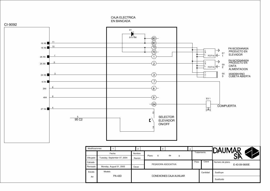
CONEXIONES CAJA AUXILIAR
Tuesday, September 07, 2004
PA-43D
E-43-09-0600E
Ramón
OscarPESADORA ASOCIATIVA
96
Escala
Plano deDibujado
Calcado
Revisado
Fecha Nombre
Modelo
Sustituido
Sustituye
Tratamiento
Peso Clave
1 2 3 4
Cantidad
Modificaciones
Numero de plano
CI-9092
26 X6
25 X6
24 X6
18 X6
16 X6
27 X4
9 X4
5
8
9
1
4
3
2
10
11
1314
D1
51V 4W
FOT14
SL
+
-
E8
FOT14
SL
+
-
E7
+
-S E6 IA30DSN15NO

PANTALLA TACTIL
BASE( 230 V AC)
ALIMENTACIONPANTALLA TACTIL
A FUSIBLES ENCUADROPOTENCIA
COM 2DB25
+ 24GND
TIERRA
A3
Monday, August 01, 2005
ESQUEMA BLOQUES
Monday, February 19, 2001
PA-43 D
E-43-09-0700E
Ramón
OscarPESADORA ASOCIATIVA
97
Escala
Plano deDibujado
Calcado
Revisado
Fecha Nombre
Modelo
Sustituido
Sustituye
Tratamiento
Peso Clave
1 2 3 4
Cantidad
Modificaciones
Numero de plano
verde 7amarillo 3
gris 2
ROJO-ROSA
AZUL-NEGRO
45
CELULA DE CARGA
azul+verdenegro+amarillo
blancorojo
malla
v+v-s-s+blindaje
CA
BLE
S LIN
EA
S FA
SE
SP
AS
AD
OS
CO
N U
NA
VU
ELTA
KITAGAWA
X2BUS I/O
X11CELULA DE CARGA
X1 TRANSFORMADOR
X7TECLADO
X6 DISPLAY
CI-9024C
CARTA MICROPROCESADOR
X9COM 1
DIP 34
POSTE 10
DIP 20
X10COM 2
WEID 5
WEID 5
WEID 8
X8BUCLE CORR.
CI-9030A
x6.1x6.2x6.3x6.4x6.5x6.6x6.7x6.8x6.9
x6.10x6.11x6.12x6.13x6.14
x2.1x2.2x2.3x2.4x2.5x2.6x2.7x2.8x2.9x2.10x2.11x2.12x2.13x2.14x2.15x2.16x2.17x2.18x2.19x2.20x2.21x2.22x2.23x2.24x2.25x2.26x2.27x2.28x2.29x2.30x2.31x2.32x2.33x2.34
x6.15x6.16x6.17x6.18x6.19x6.20
x7.1x7.2x7.3x7.4x7.5x7.6x7.7x7.8x7.9
x7.10x7.11x7.12x7.13x7.14x7.15
x1.1x1.2x1.3x1.4x1.5x1.6x1.7x1.8
X11
.1X
11.2
X11
.3X
11.4
X11
.5
X9.
2X
9.3
X9.
5X
9.7
X9.
8
x10.
2X
10.3
X10
.5X
10.7
X10
.8
X8.1X8.2X8.3X8.4X8.5
vccvccncncncd0d1d2d3d4d5d6d7ba1
VccVccba8ba7ba6ba5ba4ba3ba2ba1int3int2
s1s2s3s4
vmas5s6e
basdtackwatch
r/wd7d6d5d4d3d2d1d0
gndgnd
r/wecsrstgndgnd
in1in2in3in4q1q2q3q4q5q6q7q8ncgndvcc
11a0a11a20h0h11rs0rsnc
0V S-
S+
-V +V
RX
TX
GN
DR
TS
CT
S
RX
TX
GN
DR
TS
CT
S
+B0 BRxTx
N.C.
CONECTOR X1BUS I/O
CONECTOR X3TRANSFORMADOR
DIP 34
WEID 2 X 16
WEID 2 X 16
WEID 1 X 8WEID 1 X 16
CI-9092
x1.1x1.2x1.3x1.4x1.5x1.6x1.7x1.8x1.9
x1.10x1.11x1.12x1.13x1.14x1.15x1.16x1.17x1.18x1.19x1.20x1.21x1.22x1.23x1.24x1.25x1.26x1.27x1.28x1.29x1.30x1.31x1.32x1.33x1.34
X3.1X3.2X3.3X3.4X3.5X3.6X3.7X3.8
X4[1..32]
X6[1..32]
X5[1..16]
VccVccba8ba7ba6ba5ba4ba3ba2ba1int3int2s1s2s3s4vmas5s6ebasdtackwatchr/wd7d6d5d4d3d2d1d0gndgnd
24 P0 P19 SA036 SA024 OP0 OP
SALIDAS[1..32]
ENTRADAS[1..32]
SAL. OVER POWER[1..12]
FE
RR
ITA
KIT
AG
AW
A
����
����
��
���
��
�����
��
��
T-511
0
230
11
0
11
245
0
20
28
0
20
0
0
11
200
0
36
0
19
FA-6Z
S8VS-03024
OMRON
NL GN
D-++ -
24 O
P0
OP
19 S
A0
SA
36 S
A1
0 36
SA
1
24 P
0 P
24 OP
0 OP
19 SA
0 SA
36 SA1
0 SA1
24 P
0 P
0 (230V)
230V
TIERRA

CABLEADO ACUADROELECTRONICO
EMERGENCIA
PULSADORTIPO SETA
PARO
EAO DIFUSORVERDE
PILOTO ( MARCHA )LAM. 24V
MARCHA
EAO DIFUSORROJO
FICHADB25M
a (X9) U1
PILOTO (ALARMA)LAM. 24V
FICHADB9 H
CABLEADO ACUADROELECTRICO
A4
Monday, August 01, 2005
CUADRO DE MANDO
Thursday, July 27, 2000
PA-43 D
E-43-09-0800E
Ramón
OscarPESADORA ASOCIATIVA
98
Escala
Plano deDibujado
Calcado
Revisado
Fecha Nombre
Modelo
Sustituido
Sustituye
Tratamiento
Peso Clave
1 2 3 4
Cantidad
Modificaciones
Numero de plano
GRIS2
31 X4
21X6
19X6
19x6
28X4
60
17X6
21x6
VERDE5
B-21 21
28x4
16 X4
21 646470
12X420X6
12x4
20x6
(A1 C0)
RX
GN
D
AMARILLO3
TX
24V PANTALLAGND PANTALLA
16 X6
16x6
70 70
P1
1314
P2
1314
21222122
���� ����
DB9 DB25
FUJI UG-22-HI-CS
12
2 3 85 7 2 3 4 5 76 20
+24VGND
Rx
Tx
CT
S
GN
DR
TS
Tx
Rx
RT
SC
TS
GN
DD
SR
DT
R
P4
1314
1314

MANGUERA INTERCONEXIONCUADRO ELECTRICO A CUADRO ELECTRONICO a CUADRO
ELECTRONICOA CUADROELECTRICO
A4
Monday, August 01, 2005
Interconexion C.electronico - C. electrico
Thursday, July 27, 2000
PA-43 D
E-43-09-0900E
Ramón
OscarPESADORA ASOCIATIVA
99
Escala
Plano deDibujado
Calcado
Revisado
Fecha Nombre
Modelo
Sustituido
Sustituye
Tratamiento
Peso Clave
1 2 3 4
Cantidad
Modificaciones
Numero de plano
1 6 x4
9 27X610 13 X6
14 4 X4
8 5X4
15 20 X4
11 1 X412 2 X4
4 64 (14X4)
13 3 X4
3
7 26X4
5 70 (1X6)6 25X4
2 28 X61A2 RELE 2
9BORNA 25 (ENVASADORA)10B-80
14A2 C6
8A2 RELE 1
15S1 V1
11A2 C312A2 C4
4B-64
13A2 C5
3
7A2 C1 (95 TERMICO)
5B-706A2 C0
2B-35
16 21 X417 22 X418 23 X4
16S3 V117S4 V118S5 V1

X4
X6
X3
X1
SALIDAS
EN
TR
AD
AS
TRAFO
BUS I/O
117
1632
171
1632
1
8
X 2
X 8
X11
X 1
TRAFO
RS-232COM 1
CEL.CARGA
CEL.CARGA
BUS I/O1
5
1
8
1 5
CI-9030-A CI-9092
X5 SALIDAS
161
X 9
1
9
X 10
1
9
X12
1 5
X13
1 5
CEL.CARGA
RS-232COM 2
( SIN USO ) ( SIN USO )
TR
AF
OT
-511
FU
EN
TE
ALI
ME
NT
AC
ION
S8V
S-0
3024
BA
SE
SC
HU
KO
BUCLECORRIENTE
(MACHO)
(MACHO)
(MACHO)
A3
Monday, August 01, 2005
SITUACION CONECTORES
Friday, May 28, 1999
PA-43 D
E-43-09-1000E
Ramón
Oscar
CARTAS ELECTRONICAS
11
Escala
Plano deDibujado
Calcado
Revisado
Fecha Nombre
Modelo
Sustituido
Sustituye
Tratamiento
Peso Clave
1 2 3 4
Cantidad
Modificaciones
Numero de plano

PA-43JD
TO-2-8293-E+SVB
A TOMA DE REDELECTRICA
MA
NG
UE
RA
DE
5x2.
5
N
TRIFAS. 200V
L3L1
230V A CUADROELECTRONICO
L2
N
R1
T1
T
2-3 230V LINEA
2
LR 2K 0310
51
LR 2K 0307
1-3 380V LINEA
RC
380
X 3
VALIDA
43
MOTOR CARRUOSEL1,08 C.V. 0.18 KW1,08 A
MOTOR ELEVADOR1 C.V. 0,75 KW 3,8A
MOTOR CEPILLO0,08C.V. 0,06KW 0,55 A
PUENTE
MOTOR CINTAALIMENTADOR0,25 C.V. 0,18KW 1.08 A
RC
380
X 3
S1
R
S
TN
TRAFO D09001
CIMR-J7AZB0P2
FILTRORED FA-6Z
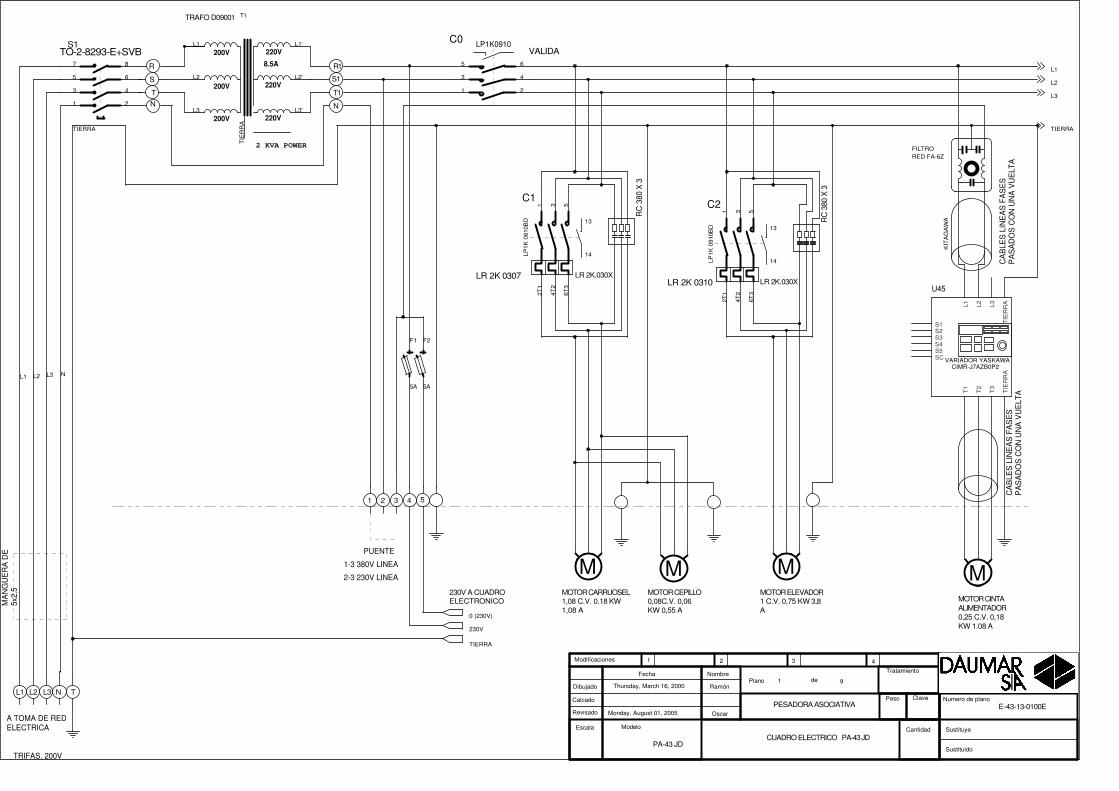
Monday, August 01, 2005PESADORA ASOCIATIVA
Thursday, March 16, 2000
PA-43 JD
E-43-13-0100E
Ramón
Oscar
CUADRO ELECTRICO PA-43 JD
91
Escala
Plano deDibujado
Calcado
Revisado
Fecha Nombre
Modelo
Sustituido
Sustituye
Tratamiento
Peso Clave
1 2 3 4
Cantidad
Modificaciones
Numero de plano
TIERRA
L1 NL2 L3
L1
L3
L2
TIERRA
M
220V200V
2 KVA POWER
8.5A
200V
200V
220V
220V
T1
L3
L2
L1
L3'
L2'
L1'
TIE
RR
A
LR 2K.030X
13
14
C1
LP1K
061
0BD
1 3 5
2T1
4T2
6T3
LR 2K.030X
13
14
C2
LP1K
091
0BD
1 3 5
2T1
4T2
6T3
M
F1
5A
F2
5A
LP1K0910C0
1
3
5
2
4
6
MM
S1
1
3
5
2
4
6
7 8
U45
VARIADOR YASKAWA
L1 L2 L3
T1
T2
T3
TIE
RR
A
S2S3S4S5SC
S1 TIE
RR
AC
AB
LES
LIN
EA
S F
AS
ES
PA
SA
DO
S C
ON
UN
A V
UE
LTA
CA
BLE
S L
INE
AS
FA
SE
SP
AS
AD
OS
CO
N U
NA
VU
ELT
A
KIT
AG
AW
A
0 (230V)
TIERRA
230V
T T
MOTOR 0,25 C.V.CINTA SAL.1 ( DERECHA )
MOTOR 0,25 C.V.CINTA SAL. 2 ( IZQUIERDA )
R
T
S
T T
MOTOR 0,25 C.V.CINTA EXTERIORDERECHA
MOTOR 0,25 C.V.CINTA EXTERIORIZQUIERDA
BORNAS REGLETERO
RC 380 X 3RC 380 X 3
LR 2K 0306 LR 2K 0306
N
CIMR-J7AZB0P2CIMR-J7AZB0P2
SALIDA DE VALIDA
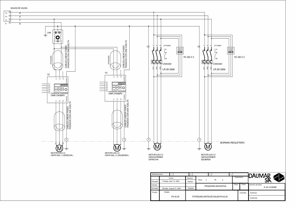
Monday, August 01, 2005PESADORA ASOCIATIVA
Tuesday, April 12, 2005
PA-43 JD
E-43-13-0200E
Ramón
RAMON
POTENCIAS CINTAS DE SALIDA PA-43 JD
92
Escala
Plano deDibujado
Calcado
Revisado
Fecha Nombre
Modelo
Sustituido
Sustituye
Tratamiento
Peso Clave
1 2 3 4
Cantidad
Modificaciones
Numero de plano
R1
S1
T1
N
CA
BLE
S L
INE
AS
FA
SE
SP
AS
AD
OS
CO
N U
NA
VU
ELT
A
CA
BLE
S L
INE
AS
FA
SE
SP
AS
AD
OS
CO
N U
NA
VU
ELT
A
KIT
AG
AW
A
V2
VARIADOR YASKAWA
L1 L2 L3
T1
T2
T3
TIE
RR
A
S2S3S4S5SC
S1 TIE
RR
A
U48
M
CA
BLE
S L
INE
AS
FA
SE
SP
AS
AD
OS
CO
N U
NA
VU
ELT
A
V3
VARIADOR YASKAWA
L1 L2 L3
T1
T2
T3
TIE
RR
A
S2S3S4S5SC
S1 TIE
RR
A
M
LR2K030X
21
22
C5 LP1K06011 3 5
2T1
4T2
6T3
M M
LR2K030X
21
22
C6 LP1K06011 3 5
2T1
4T2
6T3CA
BLE
S L
INE
AS
FA
SE
SP
AS
AD
OS
CO
N U
NA
VU
ELT
A
KIT
AG
AW
A

S. DE ENVASADORA
S. A ENVASADORA
EMERGENCIA
MARCHA
PARO
P1
P2
P3
ENVASADORADERECHA
R-C380V
S. DE ENVASADORA
S. A ENVASADORA
R-C380V
ENVASADORAIZQUIERDA
26
27
70
25
36
37
70
35
28
38
70
70
64
64
SINCRONISMO
ORIGEN
A DELGA SOPORTE DETECTORESMONTADO ENPLATOCARROUSEL
IA12DSN04NO
IA12DSN04NO
17
18
A3
Monday, August 01, 2005
ENTRADAS Y ENVASADORAS
Monday, February 19, 2001
PA-43 JD
E-43-13-0300E
Ramón
OscarPESADORA ASOCIATIVA
93
Escala
Plano deDibujado
Calcado
Revisado
Fecha Nombre
Modelo
Sustituido
Sustituye
Tratamiento
Peso Clave
1 2 3 4
Cantidad
Modificaciones
Numero de plano
CI-9092
19 X6
20 X6
21 X6
27 X6
5 X4
1 X
6
6 X4
28 X6
15 X623 X627 X6
22 X6
15 X516 X5
14 X513 X5
B-70
B-70
B-70
B-64
BLANCO
B-70
BLANCO-ROSA
GRIS-MARRON
B-64
14
1419
1918
17
19
1418
17
12
R1RELE SCHRACK (ZT5700024)
R1
1314 11
3 7
S3
1314
D3
1N4007
+
-S E5
+
-S E4
R2RELE SCHRACK (ZT5700024)
R2
1314 11
3 7
S1
1314
S2
1314
MARCHA
PARO
"VALIDA"
MOTORCARROUSEL
PIL. MARCHA
P3
PIL. ALARMA
P2
COMPUERTA
64
21
MOTORELEVADORPRODUCTO
CINTA SAL.1DERECHA
CINTA SAL. 2IZQUIERDA
24V 3W
CINTAEXTERIORDERECHA
CINTAEXTERIORIZQUIERDA
CINTA ALIMENTACION
64
P1EMERGENCIA
80
24V 3W
70 70 70
CIMR-J7AZB0P2 CIMR-J7AZB0P2 CIMR-J7AZB0P2
VARIADOR YASKAWA VARIADOR YASKAWA VARIADOR YASKAWA
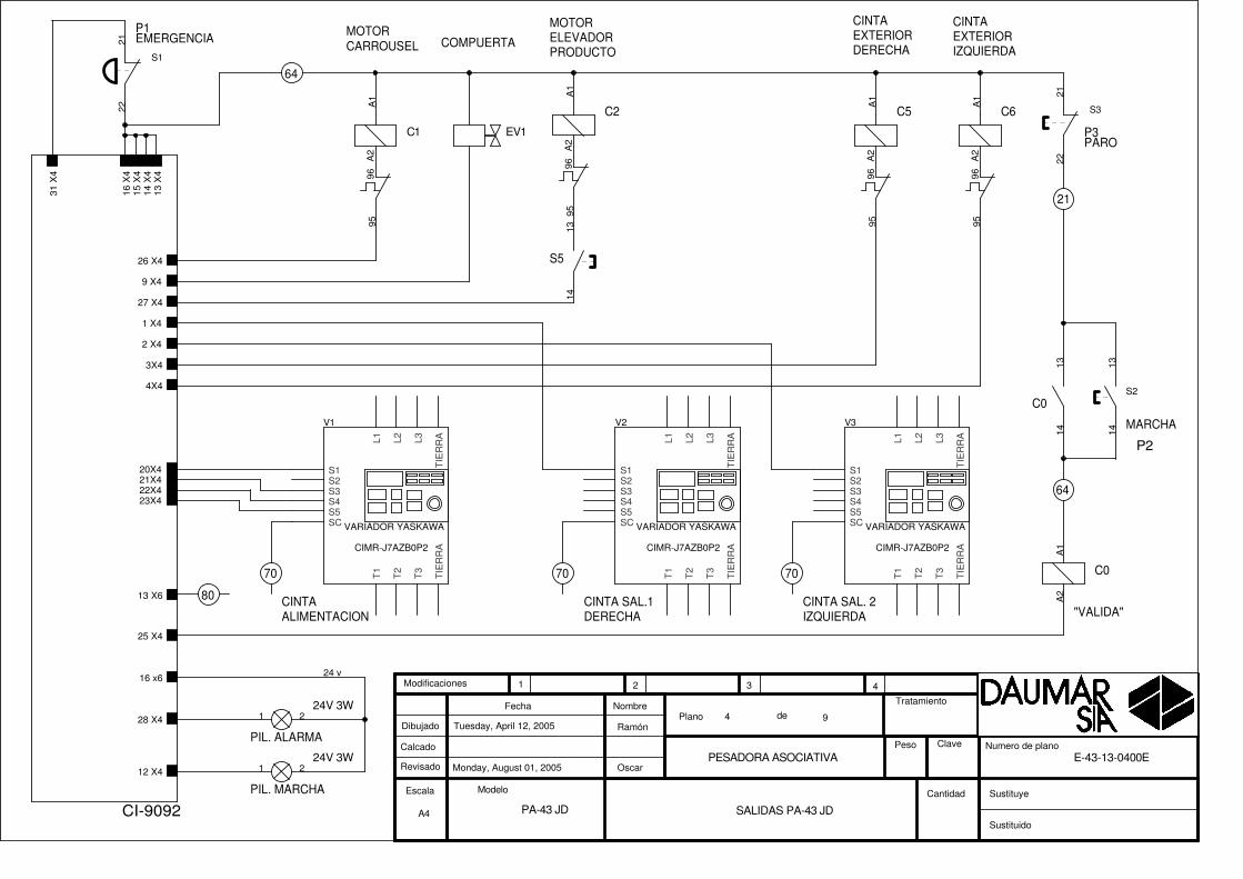
A4
Monday, August 01, 2005
SALIDAS PA-43 JD
Tuesday, April 12, 2005
PA-43 JD
E-43-13-0400E
Ramón
OscarPESADORA ASOCIATIVA
94
Escala
Plano deDibujado
Calcado
Revisado
Fecha Nombre
Modelo
Sustituido
Sustituye
Tratamiento
Peso Clave
1 2 3 4
Cantidad
Modificaciones
Numero de plano
CI-9092
12 X4
26 X4
9 X4
25 X4
27 X4
28 X4
31 X
4
13 X
4
1 X4
2 X4
20X421X422X423X4
3X4
4X4
16 x6
14 X
415
X4
16 X
4
13 X6
24 v
A2
96
C1
A1
95
A2
96
C2
A1
95
C0
1314
C0
A1
A2
S1
2122
A2
96
C5
A1
95
1 2
V1
L1 L2 L3
T1
T2
T3
TIE
RR
A
S2S3S4S5SC
S1 TIE
RR
A
S5
1314
S3
2122
EV1
A2
96
C6
A1
95
S2
1314
1 2
V3
L1 L2 L3
T1
T2
T3
TIE
RR
A
S2S3S4S5SC
S1 TIE
RR
A
V2
L1 L2 L3
T1
T2
T3
TIE
RR
A
S2S3S4S5SC
S1 TIE
RR
A

(COMUN 70V)
MANGUERA ELECTROIMANES
A4
Monday, August 01, 2005
MANGUERA ELECTROS
Thursday, October 11, 2001
PA-43 JD
E-43-13-0500E
Ramón
OscarPESADORA ASOCIATIVA
95
Escala
Plano deDibujado
Calcado
Revisado
Fecha Nombre
Modelo
Sustituido
Sustituye
Tratamiento
Peso Clave
1 2 3 4
Cantidad
Modificaciones
Numero de plano
CI-9092
13 X
5
14 X
5
15 X
5
16 X
51 X5
2 X5
3 X5
4 X5
5 X5
6 X5
7 X5
8 X5
9 X5
10 X5
6
1
5
8
3
4
7
2
10
9
E1
A1
A2
E2
A1
A2
E3
A1
A2
E6
A1
A2
E7
A1
A2
E4
A1
A2
E8
A1
A2
E9
A1
A2
E5
A1
A2
E10
A1
A2
PRODUCTO ENCINTAALIMENTACION
CUBETA ABIERTA
PRODUCTO ENELEVADOR
70
1
2
3
7080
80
7
95 C2
COMPUERTA
SELECTORELEVADORON/OFF
CAJA ELECTRICAEN BANCADA
PA18CSD04NASA
PA18CSD04NASA
1
2
3
64
8
94X4
3X4
EV 1
A4
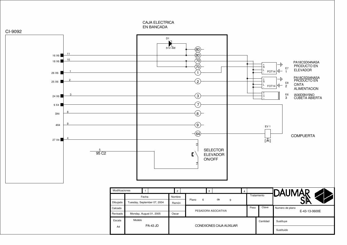
Monday, August 01, 2005
CONEXIONES CAJA AUXILIAR
Tuesday, September 07, 2004
PA-43 JD
E-43-13-0600E
Ramón
OscarPESADORA ASOCIATIVA
96
Escala
Plano deDibujado
Calcado
Revisado
Fecha Nombre
Modelo
Sustituido
Sustituye
Tratamiento
Peso Clave
1 2 3 4
Cantidad
Modificaciones
Numero de plano
CI-9092
26 X6
25 X6
24 X6
18 X6
16 X6
27 X4
9 X4
5
8
9
1
4
3
2
10
11
1314
D1
51V 4W
FOT14
SL
+
-
E8
FOT14
SL
+
-
E7
+
-S E6 IA30DSN15NO
PANTALLA TACTIL
BASE( 230 V AC)
ALIMENTACIONPANTALLA TACTIL
A FUSIBLES ENCUADROPOTENCIA
COM 2DB25
+ 24GND
TIERRA
A3
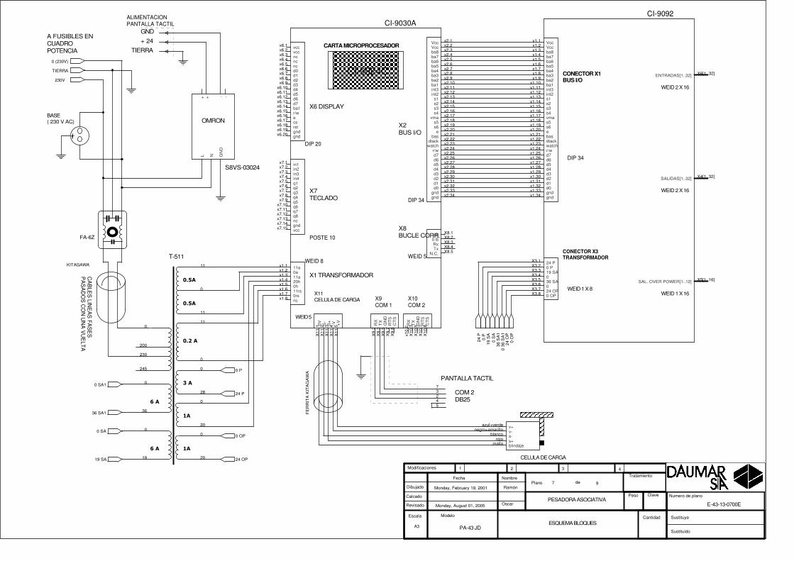
Monday, August 01, 2005
ESQUEMA BLOQUES
Monday, February 19, 2001
PA-43 JD
E-43-13-0700E
Ramón
OscarPESADORA ASOCIATIVA
97
Escala
Plano deDibujado
Calcado
Revisado
Fecha Nombre
Modelo
Sustituido
Sustituye
Tratamiento
Peso Clave
1 2 3 4
Cantidad
Modificaciones
Numero de plano
73245
CA
BLE
S LIN
EA
S FA
SE
SP
AS
AD
OS
CO
N U
NA
VU
ELTA
KITAGAWA
CELULA DE CARGA
azul+verdenegro+amarillo
blancorojo
malla
v+v-s-s+blindaje
����
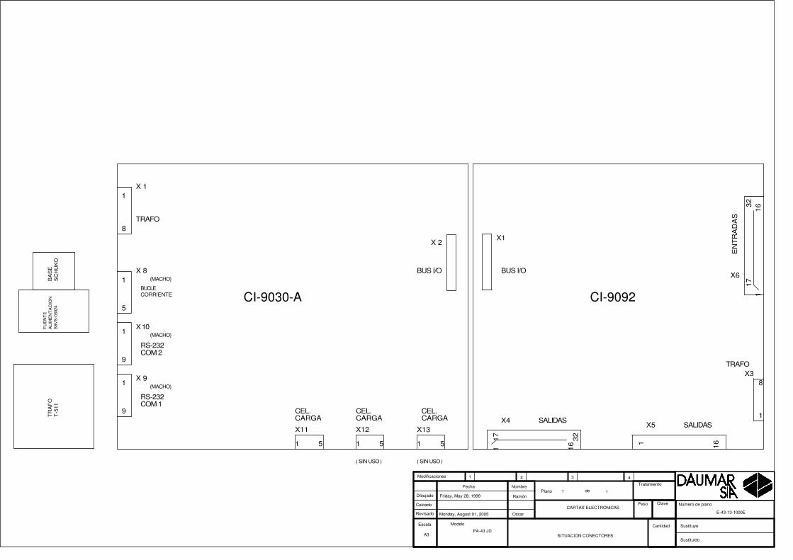
����
��
���
��
�����
��
��
T-511
0
230
11
0
11
245
0
20
28
0
20
0
0
11
200
0
36
0
19
FE
RR
ITA
KIT
AG
AW
A
CONECTOR X1BUS I/O
CONECTOR X3TRANSFORMADOR
DIP 34
WEID 2 X 16
WEID 2 X 16
WEID 1 X 8WEID 1 X 16
CI-9092
x1.1x1.2x1.3x1.4x1.5x1.6x1.7x1.8x1.9
x1.10x1.11x1.12x1.13x1.14x1.15x1.16x1.17x1.18x1.19x1.20x1.21x1.22x1.23x1.24x1.25x1.26x1.27x1.28x1.29x1.30x1.31x1.32x1.33x1.34
X3.1X3.2X3.3X3.4X3.5X3.6X3.7X3.8
X4[1..32]
X6[1..32]
X5[1..16]
VccVccba8ba7ba6ba5ba4ba3ba2ba1int3int2s1s2s3s4vmas5s6ebasdtackwatchr/wd7d6d5d4d3d2d1d0gndgnd
24 P0 P19 SA036 SA024 OP0 OP
SALIDAS[1..32]
ENTRADAS[1..32]
SAL. OVER POWER[1..12]
X2BUS I/O
X11CELULA DE CARGA
X1 TRANSFORMADOR
X7TECLADO
X6 DISPLAY
CI-9024C
CARTA MICROPROCESADOR
X9COM 1
DIP 34
POSTE 10
DIP 20
X10COM 2
WEID 5
WEID 5
WEID 8
X8BUCLE CORR.
CI-9030A
x6.1x6.2x6.3x6.4x6.5x6.6x6.7x6.8x6.9
x6.10x6.11x6.12x6.13x6.14
x2.1x2.2x2.3x2.4x2.5x2.6x2.7x2.8x2.9x2.10x2.11x2.12x2.13x2.14x2.15x2.16x2.17x2.18x2.19x2.20x2.21x2.22x2.23x2.24x2.25x2.26x2.27x2.28x2.29x2.30x2.31x2.32x2.33x2.34
x6.15x6.16x6.17x6.18x6.19x6.20
x7.1x7.2x7.3x7.4x7.5x7.6x7.7x7.8x7.9
x7.10x7.11x7.12x7.13x7.14x7.15
x1.1x1.2x1.3x1.4x1.5x1.6x1.7x1.8
X11
.1X
11.2
X11
.3X
11.4
X11
.5
X9.
2X
9.3
X9.
5X
9.7
X9.
8
x10.
2X
10.3
X10
.5X
10.7
X10
.8
X8.1X8.2X8.3X8.4X8.5
vccvccncncncd0d1d2d3d4d5d6d7ba1
VccVccba8ba7ba6ba5ba4ba3ba2ba1int3int2
s1s2s3s4
vmas5s6e
basdtackwatch
r/wd7d6d5d4d3d2d1d0
gndgnd
r/wecsrstgndgnd
in1in2in3in4q1q2q3q4q5q6q7q8ncgndvcc
11a0a11a20h0h11rs0rsnc
0V S-
S+
-V +V
RX
TX
GN
DR
TS
CT
S
RX
TX
GN
DR
TS
CT
S
+B0 BRxTx
N.C.
S8VS-03024
OMRON
NL GN
D-++ -
FA-6Z
24 O
P0
OP
19 S
A0
SA
36 S
A1
0 36
SA
1
24 P
0 P
24 OP
0 OP
19 SA
0 SA
36 SA1
0 SA1
24 P
0 P
0 (230V)
230V
TIERRA
CABLEADO ACUADROELECTRONICO
EMERGENCIA
PULSADORTIPO SETA
PARO
EAO DIFUSORVERDE
PILOTO ( MARCHA )LAM. 24V
MARCHA
EAO DIFUSORROJO
FICHADB25M
a (X9) U1
PILOTO (ALARMA)LAM. 24V
FICHADB9 H
CABLEADO ACUADROELECTRICO
A4
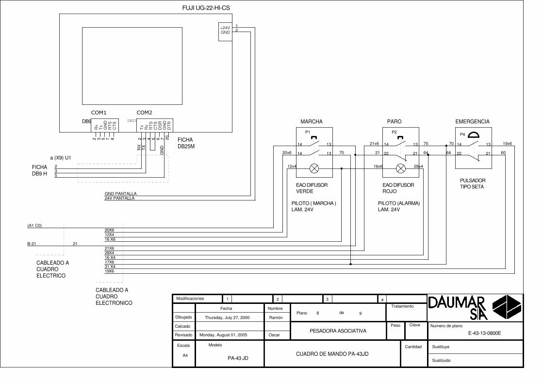
Monday, August 01, 2005
CUADRO DE MANDO PA-43JD
Thursday, July 27, 2000
PA-43 JD
E-43-13-0800E
Ramón
OscarPESADORA ASOCIATIVA
98
Escala
Plano deDibujado
Calcado
Revisado
Fecha Nombre
Modelo
Sustituido
Sustituye
Tratamiento
Peso Clave
1 2 3 4
Cantidad
Modificaciones
Numero de plano
2
31 X4
21X6
19X6
19x6
28X4
60
17X6
21x6
5
B-21 21
28x4
16 X4
21 646470
12X420X6
12x4
20x6
(A1 C0)
RX
GN
D
3
TX
24V PANTALLAGND PANTALLA
16 X6
16x6
70 70
21222122
P1
1314
P2
1314
P4
1314
1314
���� ����
DB9 DB25
FUJI UG-22-HI-CS
12
2 3 85 7 2 3 4 5 76 20
+24VGND
Rx
Tx
CT
S
GN
DR
TS
Tx
Rx
RT
SC
TS
GN
DD
SR
DT
R

MANGUERA INTERCONEXIONCUADRO ELECTRICO A CUADRO ELECTRONICO a CUADRO
ELECTRONICOA CUADROELECTRICO
A4
Monday, August 01, 2005
Interconexion C.electronico - C. electrico PA-43JD
Thursday, July 27, 2000
PA-43 JD
E-43-13-0900E
Ramón
OscarPESADORA ASOCIATIVA
99
Escala
Plano deDibujado
Calcado
Revisado
Fecha Nombre
Modelo
Sustituido
Sustituye
Tratamiento
Peso Clave
1 2 3 4
Cantidad
Modificaciones
Numero de plano
1 6 x4
9 27X610 13 X6
14 4 X4
8 5X4
15 20 X4
11 1 X412 2 X4
4 64 (14X4)
13 3 X4
3
7 26X4
5 70 (1X6)6 25X4
2 28 X61A2 RELE 2
9BORNA 25 (ENVASADORA)10B-80
14A2 C6
8A2 RELE 1
15S1 V1
11A2 C312A2 C4
4B-64
13A2 C5
3
7A2 C1 (95 TERMICO)
5B-706A2 C0
2B-35
16 21 X417 22 X418 23 X4
16S3 V117S4 V118S5 V1
X4
X6
X3
X1
SALIDAS
EN
TR
AD
AS
TRAFO
BUS I/O
117
1632
171
1632
1
8
X 2
X 8
X11
X 1
TRAFO
RS-232COM 1
CEL.CARGA
CEL.CARGA
BUS I/O1
5
1
8
1 5
CI-9030-A CI-9092
X5 SALIDAS
161
X 9
1
9
X 10
1
9
X12
1 5
X13
1 5
CEL.CARGA
RS-232COM 2
( SIN USO ) ( SIN USO )
TR
AF
OT
-511
BA
SE
SC
HU
KO
BUCLECORRIENTE
(MACHO)
(MACHO)
(MACHO)
FU
EN
TE
ALI
ME
NT
AC
ION
S8V
S-0
3024
A3
Monday, August 01, 2005
SITUACION CONECTORES
Friday, May 28, 1999
PA-43 JD
E-43-13-1000E
Ramón
Oscar
CARTAS ELECTRONICAS
11
Escala
Plano deDibujado
Calcado
Revisado
Fecha Nombre
Modelo
Sustituido
Sustituye
Tratamiento
Peso Clave
1 2 3 4
Cantidad
Modificaciones
Numero de plano

PA-43S

RC
380
X 3
1-3 380V LINEA
RC
380
X 3
TO-2-8293-E+SVB
A TOMA DE REDELECTRICA
2-3 230V LINEA
MA
NG
UE
RA
DE
5x2.
5
N
BORNASREGLETERO
TRIFAS. 380V
5
L3
3
VALIDA
1
L1
230V A CUADROELECTRONICO
MOTOR ELEVADOR0,75 C.V. 0,55 KW
4
L2
2
MOTOR CINTAALIMENTADOR0,25 C.V. 0,18KW
PUENTE
MOTOR CARRUOSEL0,5 C.V. 0,36 KW
LR 2K 0306 LR 2K 0308
N
L1
L2
L3
FILTRO REDFA-6Z
CIMR-J7AZB0P2
Monday, August 01, 2005PESADORA ASOCIATIVA
Thursday, March 16, 2000
PA-43 S
E-43-10-0100
Ramón
Oscar
CUADRO ELECTRICO 1/2
91
Escala
Plano deDibujado
Calcado
Revisado
Fecha Nombre
Modelo
Sustituido
Sustituye
Tratamiento
Peso Clave
1 2 3 4
Cantidad
Modificaciones
Numero de plano
N
TIERRA
L2 L3L1
L2
L3
TIERRA
L1
LR 2K.030X
13
14
C2
LP1K
091
0BD
1 3 5
2T1
4T2
6T3
LR 2K.030X
13
14
C1
LP1K
061
0BD
1 3 5
2T1
4T2
6T3
M M
F1
5A
F2
5A
M
LP1K0910C0
1
3
5
2
4
6
S1
1
3
5
2
4
6
7 8
U45
VARIADOR YASKAWA
L1 L2 L3
T1
T2
T3
TIE
RR
A
S2S3S4S5SC
S1 TIE
RR
AC
AB
LES
LIN
EA
S F
AS
ES
PA
SA
DO
S C
ON
UN
A V
UE
LTA
KIT
AG
AW
A
CA
BLE
S L
INE
AS
FA
SE
SP
AS
AD
OS
CO
N U
NA
VU
ELT
A
0 (230V)
230V
TIERRA
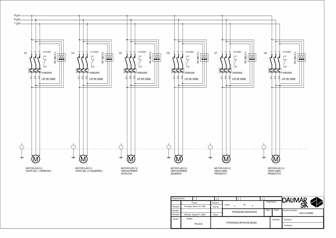
MOTOR 0,25 C.V.CINTA SAL.1 ( DERECHA )
MOTOR 0,25 C.V.CINTA SAL. 2 ( IZQUIERDA )
R
T
S
RC
380
X 3
RC
380
X 3
LR 2K 0306 LR 2K 0306
MOTOR 0,25 C.V.CINTA EXTERIORDERECHA
MOTOR 0,25 C.V.CINTA EXTERIORIZQUIERDA
RC
380
X 3
RC
380
X 3
LR 2K 0306 LR 2K 0306
RC
380
X 3
LR 2K 0306
RC
380
X 3
LR 2K 0306
MOTOR 0,25 C.V.CINTA CAIDAPRODUCTO 1
MOTOR 0,25 C.V.CINTA CAIDAPRODUCTO 2
Monday, August 01, 2005PESADORA ASOCIATIVA
Thursday, March 16, 2000
PA-43 S
E43-10-0200E
Ramón
Oscar
POTENCIAS CINTAS DE SALIDA
92
Escala
Plano deDibujado
Calcado
Revisado
Fecha Nombre
Modelo
Sustituido
Sustituye
Tratamiento
Peso Clave
1 2 3 4
Cantidad
Modificaciones
Numero de plano
L1
L2
L3
M MM M M M
LR2K030X
21
22
C5 LP1K06011 3 5
2T1
4T2
6T3
LR2K030X
21
22
C6 LP1K06011 3 5
2T1
4T2
6T3
LR2K030X
21
22
C3 LP1K06011 3 5
2T1
4T2
6T3
LR2K030X
21
22
C4 LP1K06011 3 5
2T1
4T2
6T3
LR2K030X
21
22
C8 LP1K06011 3 5
2T1
4T2
6T3
LR2K030X
21
22
C7 LP1K06011 3 5
2T1
4T2
6T3

S. DE ENVASADORA
S. A ENVASADORA
EMERGENCIA
MARCHA
PARO
P1
P2
P3
ENVASADORADERECHA
R-C380V
S. DE ENVASADORA
S. A ENVASADORA
R-C380V
ENVASADORAIZQUIERDA
26
27
70
25
36
37
70
35
28
38
70
70
64
64
SINCRONISMO
ORIGEN
A DELGA SOPORTE DETECTORESMONTADO ENPLATOCARROUSEL
IA12DSN04NO
IA12DSN04NO
17
18
A3
Monday, August 01, 2005
ENTRADAS Y ENVASADORAS
Monday, February 19, 2001
PA-43S
E-43-10-0300E
Ramón
OscarPESADORA ASOCIATIVA
93
Escala
Plano deDibujado
Calcado
Revisado
Fecha Nombre
Modelo
Sustituido
Sustituye
Tratamiento
Peso Clave
1 2 3 4
Cantidad
Modificaciones
Numero de plano
CI-9092
19 X6
20 X6
21 X6
27 X6
5 X4
1 X
6
6 X4
28 X6
15 X623 X627 X6
22 X6
15 X516 X5
14 X513 X5
B-70
B-70
B-70
B-64
BLANCO
B-70
BLANCO-ROSA
GRIS-MARRON
B-64
14
1419
1918
17
19
1418
17
12
S3
1314
R1RELE SCHRACK (ZT5700024)
R1
1314 11
3 7
D3
1N4007
+
-S E5
+
-S E4
R2RELE SCHRACK (ZT5700024)
R2
1314 11
3 7
S1
1314
S2
1314
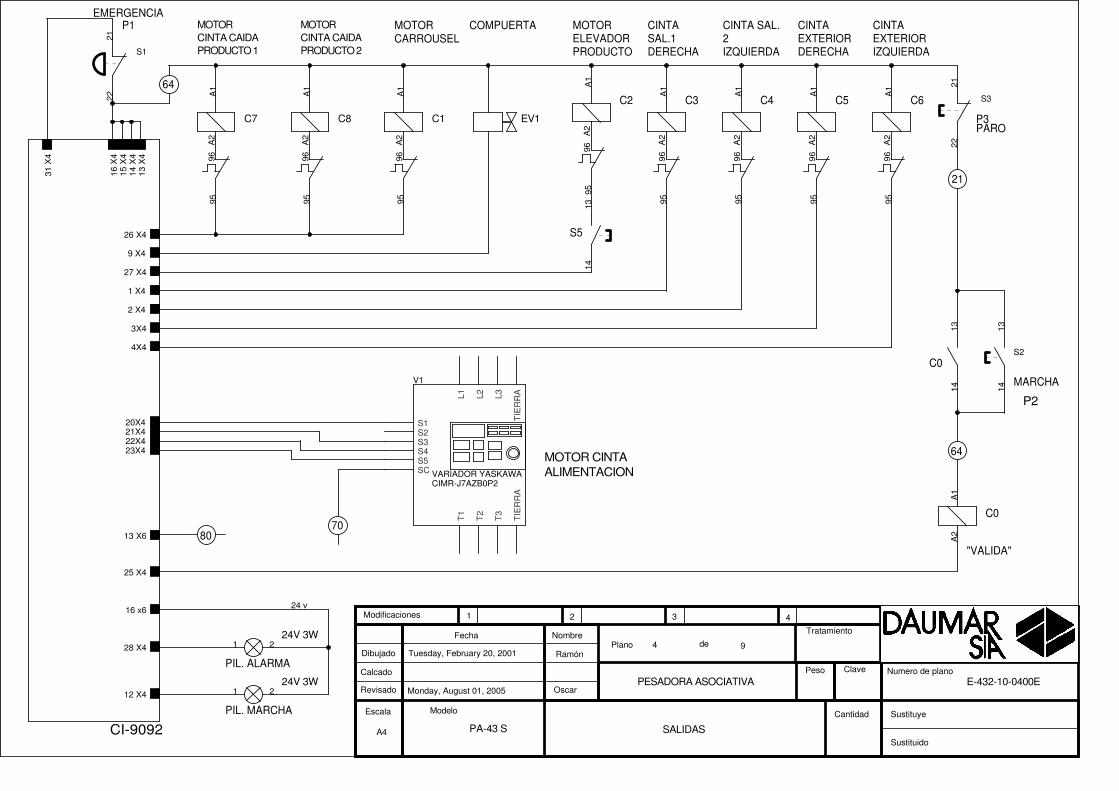
MARCHA
PARO
"VALIDA"
MOTORCARROUSEL
PIL. MARCHA
P3
PIL. ALARMA
P2
COMPUERTA
64
21
MOTORELEVADORPRODUCTO
CINTASAL.1DERECHA
CINTA SAL.2IZQUIERDA
24V 3W
CINTAEXTERIORDERECHA
CINTAEXTERIORIZQUIERDA
MOTOR CINTAALIMENTACION
64
P1EMERGENCIA
80
24V 3W
70
MOTOR CINTA CAIDAPRODUCTO 1
MOTOR CINTA CAIDAPRODUCTO 2
CIMR-J7AZB0P2
A4
Monday, August 01, 2005
SALIDAS
Tuesday, February 20, 2001
PA-43 S
E-432-10-0400E
Ramón
OscarPESADORA ASOCIATIVA
94
Escala
Plano deDibujado
Calcado
Revisado
Fecha Nombre
Modelo
Sustituido
Sustituye
Tratamiento
Peso Clave
1 2 3 4
Cantidad
Modificaciones
Numero de plano
CI-9092
12 X4
26 X4
9 X4
25 X4
27 X4
28 X4
31 X
4
13 X
4
1 X4
2 X4
20X421X422X423X4
3X4
4X4
16 x6
14 X
415
X4
16 X
4
13 X6
24 v
S3
2122
C0
A1
A2
S1
2122
S2
1314
1 2
C0
1314
1 2
A2
96
C2
A1
95
EV1
A2
96
C1
A1
95
V1
VARIADOR YASKAWAL1 L2 L3
T1
T2
T3
TIE
RR
A
S2S3S4S5SC
S1 TIE
RR
A
A2
96
C7
A1
95
A2
96
C8
A1
95
S5
1314
A2
96
C5
A1
95
A2
96
C6
A1
95
A2
96
C3
A1
95
A2
96
C4
A1
95

(COMUN 70V)
MANGUERA ELECTROIMANES
A4
Monday, August 01, 2005
MANGUERA ELECTROS
Thursday, October 11, 2001
PA-43 S
E-43-10-0500E
Ramón
OscarPESADORA ASOCIATIVA
95
Escala
Plano deDibujado
Calcado
Revisado
Fecha Nombre
Modelo
Sustituido
Sustituye
Tratamiento
Peso Clave
1 2 3 4
Cantidad
Modificaciones
Numero de plano
CI-9092
13 X
5
14 X
5
15 X
5
16 X
51 X5
2 X5
3 X5
4 X5
5 X5
6 X5
7 X5
8 X5
9 X5
10 X5
6
1
5
8
3
4
7
2
10
9
E2
A1
A2
E3
A1
A2
E7
A1
A2
E4
A1
A2
E1
A1
A2
E5
A1
A2
E6
A1
A2
E10
A1
A2
E8
A1
A2
E9
A1
A2

PRODUCTO ENCINTAALIMENTACION
CUBETA ABIERTA
PRODUCTO ENELEVADOR
70
1
2
3
7080
80
7
95 C2
COMPUERTA
SELECTORELEVADORON/OFF
CAJA ELECTRICAEN BANCADA
PA18CSD04NASA
PA18CSD04NASA
1
2
3
64
8
94X4
3X4
EV 1
A4
Monday, August 01, 2005
CONEXIONES CAJA AUXILIAR
Tuesday, September 07, 2004
PA-43 S
E-43-10-0600E
Ramón
OscarPESADORA ASOCIATIVA
96
Escala
Plano deDibujado
Calcado
Revisado
Fecha Nombre
Modelo
Sustituido
Sustituye
Tratamiento
Peso Clave
1 2 3 4
Cantidad
Modificaciones
Numero de plano
CI-9092
26 X6
25 X6
24 X6
18 X6
16 X6
27 X4
9 X4
5
8
9
1
4
3
2
10
11
1314
D1
51V 4W
FOT14
SL
+
-
E8
FOT14
SL
+
-
E7
+
-S E6 IA30DSN15NO

PANTALLA TACTIL
BASE( 230 V AC)
ALIMENTACIONPANTALLA TACTIL
A FUSIBLES ENCUADROPOTENCIA
COM 2DB25
+ 24GND
TIERRA
A3
Monday, August 01, 2005
ESQUEMA BLOQUES
Monday, February 19, 2001
PA-43 S
E-43-10-0700E
Ramón
OscarPESADORA ASOCIATIVA
97
Escala
Plano deDibujado
Calcado
Revisado
Fecha Nombre
Modelo
Sustituido
Sustituye
Tratamiento
Peso Clave
1 2 3 4
Cantidad
Modificaciones
Numero de plano
verde 7amarillo 3
gris 2
ROJO-ROSA
AZUL-NEGRO
45
X2BUS I/O
X11CELULA DE CARGA
X1 TRANSFORMADOR
X7TECLADO
X6 DISPLAY
CI-9024C
CARTA MICROPROCESADOR
X9COM 1
DIP 34
POSTE 10
DIP 20
X10COM 2
WEID 5
WEID 5
WEID 8
X8BUCLE CORR.
CI-9030A
x6.1x6.2x6.3x6.4x6.5x6.6x6.7x6.8x6.9
x6.10x6.11x6.12x6.13x6.14
x2.1x2.2x2.3x2.4x2.5x2.6x2.7x2.8x2.9x2.10x2.11x2.12x2.13x2.14x2.15x2.16x2.17x2.18x2.19x2.20x2.21x2.22x2.23x2.24x2.25x2.26x2.27x2.28x2.29x2.30x2.31x2.32x2.33x2.34
x6.15x6.16x6.17x6.18x6.19x6.20
x7.1x7.2x7.3x7.4x7.5x7.6x7.7x7.8x7.9
x7.10x7.11x7.12x7.13x7.14x7.15
x1.1x1.2x1.3x1.4x1.5x1.6x1.7x1.8
X11
.1X
11.2
X11
.3X
11.4
X11
.5
X9.
2X
9.3
X9.
5X
9.7
X9.
8
x10.
2X
10.3
X10
.5X
10.7
X10
.8
X8.1X8.2X8.3X8.4X8.5
vccvccncncncd0d1d2d3d4d5d6d7ba1
VccVccba8ba7ba6ba5ba4ba3ba2ba1int3int2
s1s2s3s4
vmas5s6e
basdtackwatch
r/wd7d6d5d4d3d2d1d0
gndgnd
r/wecsrstgndgnd
in1in2in3in4q1q2q3q4q5q6q7q8ncgndvcc
11a0a11a20h0h11rs0rsnc
0V S-
S+
-V +V
RX
TX
GN
DR
TS
CT
S
RX
TX
GN
DR
TS
CT
S
+B0 BRxTx
N.C.
CA
BLE
S LIN
EA
S FA
SE
SP
AS
AD
OS
CO
N U
NA
VU
ELTA
KITAGAWA
CELULA DE CARGA
azul+verdenegro+amarillo
blancorojo
malla
v+v-s-s+blindaje
FA-6Z
����
����
��
���
��
�����
��
��
T-511
0
230
11
0
11
245
0
20
28
0
20
0
0
11
200
0
36
0
19
FE
RR
ITA
KIT
AG
AW
A
CONECTOR X1BUS I/O
CONECTOR X3TRANSFORMADOR
DIP 34
WEID 2 X 16
WEID 2 X 16
WEID 1 X 8WEID 1 X 16
CI-9092
x1.1x1.2x1.3x1.4x1.5x1.6x1.7x1.8x1.9
x1.10x1.11x1.12x1.13x1.14x1.15x1.16x1.17x1.18x1.19x1.20x1.21x1.22x1.23x1.24x1.25x1.26x1.27x1.28x1.29x1.30x1.31x1.32x1.33x1.34
X3.1X3.2X3.3X3.4X3.5X3.6X3.7X3.8
X4[1..32]
X6[1..32]
X5[1..16]
VccVccba8ba7ba6ba5ba4ba3ba2ba1int3int2s1s2s3s4vmas5s6ebasdtackwatchr/wd7d6d5d4d3d2d1d0gndgnd
24 P0 P19 SA036 SA024 OP0 OP
SALIDAS[1..32]
ENTRADAS[1..32]
SAL. OVER POWER[1..12]
S8VS-03024
OMRON
NL GN
D-++ -
24 O
P0
OP
19 S
A0
SA
36 S
A1
0 36
SA
1
24 P
0 P
24 OP
0 OP
19 SA
0 SA
36 SA1
0 SA1
24 P
0 P
0 (230V)
230V
TIERRA

CABLEADO ACUADROELECTRONICO
EMERGENCIA
PULSADORTIPO SETA
PARO
EAO DIFUSORVERDE
PILOTO ( MARCHA )LAM. 24V
MARCHA
EAO DIFUSORROJO
FICHADB25M
a (X9) U1
PILOTO (ALARMA)LAM. 24V
FICHADB9 H
CABLEADO ACUADROELECTRICO
A4
Monday, August 01, 2005
CUADRO DE MANDO
Thursday, July 27, 2000
PA-43 S
E-43-10-0800E
Ramón
OscarPESADORA ASOCIATIVA
98
Escala
Plano deDibujado
Calcado
Revisado
Fecha Nombre
Modelo
Sustituido
Sustituye
Tratamiento
Peso Clave
1 2 3 4
Cantidad
Modificaciones
Numero de plano
2
31 X4
21X6
19X6
19x6
28X4
60
17X6
21x6
5
B-21 21
28x4
16 X4
21 646470
12X420X6
12x4
20x6
(A1 C0)
RX
GN
D
3
TX
24V PANTALLAGND PANTALLA
16 X6
16x6
70 70
P2
1314
P1
1314
2122 21221314
P4
1314
���� ����
DB9 DB25
FUJI UG-22-HI-CS
12
2 3 85 7 2 3 4 5 76 20
+24VGND
Rx
Tx
CT
S
GN
DR
TS
Tx
Rx
RT
SC
TS
GN
DD
SR
DT
R

MANGUERA INTERCONEXIONCUADRO ELECTRICO A CUADRO ELECTRONICO a CUADRO
ELECTRONICOA CUADROELECTRICO
A4
Monday, August 01, 2005
Interconexion C.electronico - C. electrico
Thursday, July 27, 2000
PA-43 S
E-43-10-0900E
Ramón
OscarPESADORA ASOCIATIVA
99
Escala
Plano deDibujado
Calcado
Revisado
Fecha Nombre
Modelo
Sustituido
Sustituye
Tratamiento
Peso Clave
1 2 3 4
Cantidad
Modificaciones
Numero de plano
1 6 x4
9 27X610 13 X6
14 4 X4
8 5X4
15 20 X4
11 1 X412 2 X4
4 64 (14X4)
13 3 X4
3
7 26X4
5 70 (1X6)6 25X4
2 28 X61A2 RELE 2
9BORNA 25 (ENVASADORA)10B-80
14A2 C6
8A2 RELE 1
15S1 V1
11A2 C312A2 C4
4B-64
13A2 C5
3
7A2 C1 (95 TERMICO)
5B-706A2 C0
2B-35
16 21 X417 22 X418 23 X4
16S3 V117S4 V118S5 V1

X4
X6
X3
X1
SALIDAS
EN
TR
AD
AS
TRAFO
BUS I/O
117
1632
171
1632
1
8
X 2
X 8
X11
X 1
TRAFO
RS-232COM 1
CEL.CARGA
CEL.CARGA
BUS I/O1
5
1
8
1 5
CI-9030-A CI-9092
X5 SALIDAS
161
X 9
1
9
X 10
1
9
X12
1 5
X13
1 5
CEL.CARGA
RS-232COM 2
( SIN USO ) ( SIN USO )
TR
AF
OT
-511
FU
EN
TE
ALI
ME
NT
AC
ION
S8V
S-0
3024
BA
SE
SC
HU
KO
BUCLECORRIENTE
(MACHO)
(MACHO)
(MACHO)
A3
Monday, August 01, 2005
SITUACION CONECTORES
Friday, May 28, 1999
PA-43 S
E-43-10-1000E
Ramón
Oscar
CARTAS ELECTRONICAS
11
Escala
Plano deDibujado
Calcado
Revisado
Fecha Nombre
Modelo
Sustituido
Sustituye
Tratamiento
Peso Clave
1 2 3 4
Cantidad
Modificaciones
Numero de plano
PA-43V
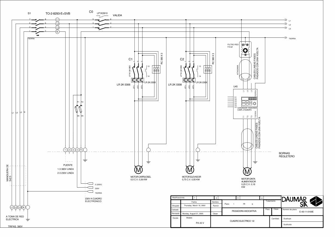
RC
380
X 3
1-3 380V LINEA
RC
380
X 3
TO-2-8293-E+SVB
A TOMA DE REDELECTRICA
2-3 230V LINEA
MA
NG
UE
RA
DE
5x2.
5
N
BORNASREGLETERO
TRIFAS. 380V
5
L3
3
VALIDA
1
L1
230V A CUADROELECTRONICO
MOTOR ELEVADOR0,75 C.V. 0,55 KW
4
L2
2
MOTOR CINTAALIMENTADOR0,25 C.V. 0,18KW
PUENTE
MOTOR CARRUOSEL0,5 C.V. 0,36 KW
LR 2K 0306 LR 2K 0308
N
L1
L2
L3
FILTRO REDFA-6Z
CIMR-J7AZB0P2
Monday, August 01, 2005PESADORA ASOCIATIVA
Thursday, March 16, 2000
PA-43 V
E-43-11-0100E
Ramón
Oscar
CUADRO ELECTRICO 1/2
91
Escala
Plano deDibujado
Calcado
Revisado
Fecha Nombre
Modelo
Sustituido
Sustituye
Tratamiento
Peso Clave
1 2 3 4
Cantidad
Modificaciones
Numero de plano
N
TIERRA
L2 L3L1
L2
L3
TIERRA
L1
LR 2K.030X
13
14
C2
LP1K
091
0BD
1 3 5
2T1
4T2
6T3
LR 2K.030X
13
14
C1
LP1K
061
0BD
1 3 5
2T1
4T2
6T3
M M
F1
5A
F2
5A
M
LP1K0910C0
1
3
5
2
4
6
S1
1
3
5
2
4
6
7 8
U45
VARIADOR YASKAWA
L1 L2 L3
T1
T2
T3
TIE
RR
A
S2S3S4S5SC
S1 TIE
RR
AC
AB
LES
LIN
EA
S F
AS
ES
PA
SA
DO
S C
ON
UN
A V
UE
LTA
KIT
AG
AW
A
CA
BLE
S L
INE
AS
FA
SE
SP
AS
AD
OS
CO
N U
NA
VU
ELT
A
0 (230V)
230V
TIERRA
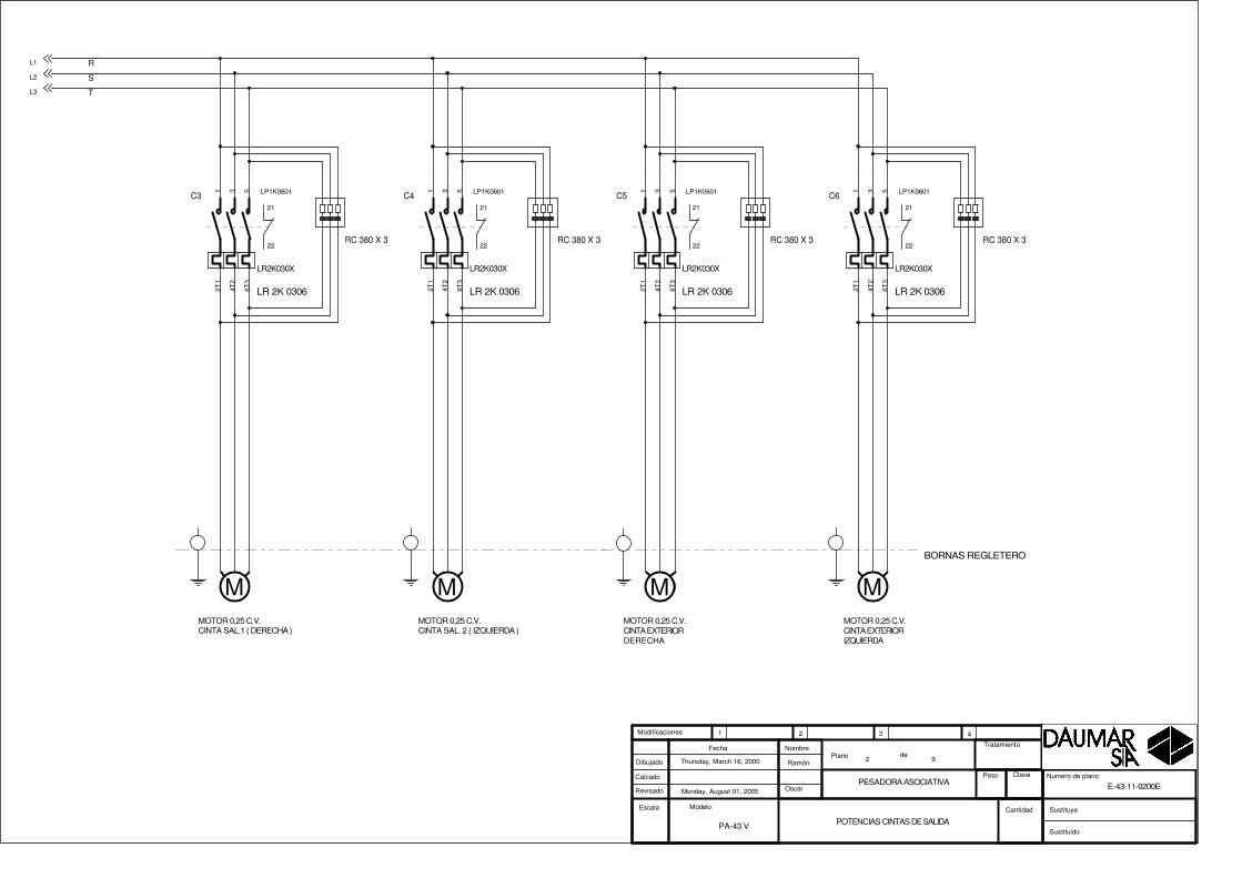
MOTOR 0,25 C.V.CINTA SAL.1 ( DERECHA )
MOTOR 0,25 C.V.CINTA SAL. 2 ( IZQUIERDA )
R
T
S
RC 380 X 3RC 380 X 3
LR 2K 0306 LR 2K 0306
MOTOR 0,25 C.V.CINTA EXTERIORDERECHA
MOTOR 0,25 C.V.CINTA EXTERIORIZQUIERDA
BORNAS REGLETERO
RC 380 X 3RC 380 X 3
LR 2K 0306 LR 2K 0306
Monday, August 01, 2005PESADORA ASOCIATIVA
Thursday, March 16, 2000
PA-43 V
E-43-11-0200E
Ramón
Oscar
POTENCIAS CINTAS DE SALIDA
92
Escala
Plano deDibujado
Calcado
Revisado
Fecha Nombre
Modelo
Sustituido
Sustituye
Tratamiento
Peso Clave
1 2 3 4
Cantidad
Modificaciones
Numero de plano
L1
L2
L3
M M M M
LR2K030X
21
22
C5 LP1K06011 3 5
2T1
4T2
6T3
LR2K030X
21
22
C6 LP1K06011 3 5
2T1
4T2
6T3
LR2K030X
21
22
C3 LP1K06011 3 5
2T1
4T2
6T3
LR2K030X
21
22
C4 LP1K06011 3 5
2T1
4T2
6T3

S. DE ENVASADORA
S. A ENVASADORA
EMERGENCIA
MARCHA
PARO
P1
P2
P3
ENVASADORADERECHA
R-C380V
S. DE ENVASADORA
S. A ENVASADORA
R-C380V
ENVASADORAIZQUIERDA
26
27
70
25
36
37
70
35
28
38
70
70
64
64
SINCRONISMO
ORIGEN
A DELGA SOPORTE DETECTORESMONTADO ENPLATOCARROUSEL
IA12DSN04NO
IA12DSN04NO
17
18
A3
Monday, August 01, 2005
ENTRADAS Y ENVASADORAS
Monday, February 19, 2001
PA-43 V
E-43-11-0300E
Ramón
OscarPESADORA ASOCIATIVA
93
Escala
Plano deDibujado
Calcado
Revisado
Fecha Nombre
Modelo
Sustituido
Sustituye
Tratamiento
Peso Clave
1 2 3 4
Cantidad
Modificaciones
Numero de plano
CI-9092
19 X6
20 X6
21 X6
27 X6
5 X4
1 X
6
6 X4
28 X6
15 X623 X6
27 X6
22 X6
15 X516 X5
14 X513 X5
B-70
B-70
B-70
B-64
BLANCO
B-70
BLANCO-ROSA
GRIS-MARRON
B-64
14
1419
1918
17
19
1418
17
12
S3
1314
R1RELE SCHRACK (ZT5700024)
R1
1314 11
3 7
D3
1N4007
+
-S E5
+
-S E4
R2RELE SCHRACK (ZT5700024)
R2
1314 11
3 7
S1
1314
S2
1314

MARCHA
PARO
"VALIDA"
MOTORCARROUSEL
PIL. MARCHA
P3
PIL. ALARMA
P2
COMPUERTA
64
21
MOTORELEVADORPRODUCTO
CINTA SAL.1DERECHA
CINTA SAL. 2IZQUIERDA
24V 3W
CINTAEXTERIORDERECHA
CINTAEXTERIORIZQUIERDA
MOTOR CINTAALIMENTACION
64
P1EMERGENCIA
80
24V 3W
70
CIMR-J7AZB0P2
A4
Monday, August 01, 2005
SALIDAS
Tuesday, February 20, 2001
PA-43 V
E-43-11-0400E
Ramón
OscarPESADORA ASOCIATIVA
94
Escala
Plano deDibujado
Calcado
Revisado
Fecha Nombre
Modelo
Sustituido
Sustituye
Tratamiento
Peso Clave
1 2 3 4
Cantidad
Modificaciones
Numero de plano
CI-9092
12 X4
26 X4
9 X4
25 X4
27 X4
28 X4
31 X
4
13 X
4
1 X4
2 X4
20X421X422X423X4
3X4
4X4
16 x6
14 X
415
X4
16 X
4
13 X6
24 v
S3
2122
C0
A1
A2
S2
1314
1 2
S1
2122
C0
1314
1 2
A2
96
C2
A1
95
EV1
A2
96
C1
A1
95
V1
VARIADOR YASKAWAL1 L2 L3
T1
T2
T3
TIE
RR
A
S2S3S4S5SC
S1 TIE
RR
A
S5
1314
A2
96
C5
A1
95
A2
96
C6
A1
95
A2
96
C3
A1
95
A2
96
C4
A1
95
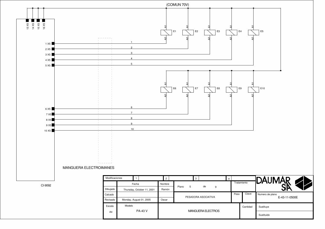
(COMUN 70V)
MANGUERA ELECTROIMANES
A4
Monday, August 01, 2005
MANGUERA ELECTROS
Thursday, October 11, 2001
PA-43 V
E-43-11-0500E
Ramón
OscarPESADORA ASOCIATIVA
95
Escala
Plano deDibujado
Calcado
Revisado
Fecha Nombre
Modelo
Sustituido
Sustituye
Tratamiento
Peso Clave
1 2 3 4
Cantidad
Modificaciones
Numero de plano
CI-9092
13 X
5
14 X
5
15 X
5
16 X
51 X5
2 X5
3 X5
4 X5
5 X5
6 X5
7 X5
8 X5
9 X5
10 X5
6
1
5
8
3
4
7
2
10
9
E3
A1
A2
E2
A1
A2
E1
A1
A2
E4
A1
A2
E7
A1
A2
E6
A1
A2
E5
A1
A2
E9
A1
A2
E8
A1
A2
E10
A1
A2

PRODUCTO ENCINTAALIMENTACION
CUBETA ABIERTA
PRODUCTO ENELEVADOR
70
1
2
3
7080
80
7
95 C2
COMPUERTA
SELECTORELEVADORON/OFF
CAJA ELECTRICAEN BANCADA
PA18CSD04NASA
PA18CSD04NASA
1
2
3
64
8
94X4
3X4
EV 1
A4
Monday, August 01, 2005
CONEXIONES CAJA AUXILIAR
Tuesday, September 07, 2004
PA-43 V
E-43-11-0600E
Ramón
OscarPESADORA ASOCIATIVA
96
Escala
Plano deDibujado
Calcado
Revisado
Fecha Nombre
Modelo
Sustituido
Sustituye
Tratamiento
Peso Clave
1 2 3 4
Cantidad
Modificaciones
Numero de plano
CI-9092
26 X6
25 X6
24 X6
18 X6
16 X6
27 X4
9 X4
5
8
9
1
4
3
2
10
11
1314
FOT14
SL
+
-
E7
FOT14
SL
+
-
E8
D1
51V 4W
+
-S E6 IA30DSN15NO
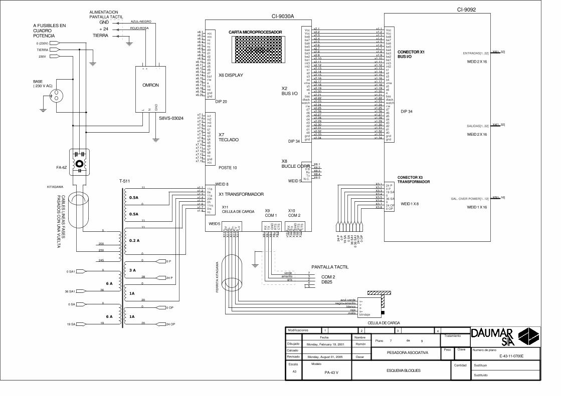
PANTALLA TACTIL
BASE( 230 V AC)
ALIMENTACIONPANTALLA TACTIL
A FUSIBLES ENCUADROPOTENCIA
COM 2DB25
+ 24GND
TIERRA
A3
Monday, August 01, 2005
ESQUEMA BLOQUES
Monday, February 19, 2001
PA-43 V
E-43-11-0700E
Ramón
OscarPESADORA ASOCIATIVA
97
Escala
Plano deDibujado
Calcado
Revisado
Fecha Nombre
Modelo
Sustituido
Sustituye
Tratamiento
Peso Clave
1 2 3 4
Cantidad
Modificaciones
Numero de plano
verde 7amarillo 3
gris 2
ROJO-ROSA
AZUL-NEGRO
45
X2BUS I/O
X11CELULA DE CARGA
X1 TRANSFORMADOR
X7TECLADO
X6 DISPLAY
CI-9024C
CARTA MICROPROCESADOR
X9COM 1
DIP 34
POSTE 10
DIP 20
X10COM 2
WEID 5
WEID 5
WEID 8
X8BUCLE CORR.
CI-9030A
x6.1x6.2x6.3x6.4x6.5x6.6x6.7x6.8x6.9
x6.10x6.11x6.12x6.13x6.14
x2.1x2.2x2.3x2.4x2.5x2.6x2.7x2.8x2.9x2.10x2.11x2.12x2.13x2.14x2.15x2.16x2.17x2.18x2.19x2.20x2.21x2.22x2.23x2.24x2.25x2.26x2.27x2.28x2.29x2.30x2.31x2.32x2.33x2.34
x6.15x6.16x6.17x6.18x6.19x6.20
x7.1x7.2x7.3x7.4x7.5x7.6x7.7x7.8x7.9
x7.10x7.11x7.12x7.13x7.14x7.15
x1.1x1.2x1.3x1.4x1.5x1.6x1.7x1.8
X11
.1X
11.2
X11
.3X
11.4
X11
.5
X9.
2X
9.3
X9.
5X
9.7
X9.
8
x10.
2X
10.3
X10
.5X
10.7
X10
.8
X8.1X8.2X8.3X8.4X8.5
vccvccncncncd0d1d2d3d4d5d6d7ba1
VccVccba8ba7ba6ba5ba4ba3ba2ba1int3int2
s1s2s3s4
vmas5s6e
basdtackwatch
r/wd7d6d5d4d3d2d1d0
gndgnd
r/wecsrstgndgnd
in1in2in3in4q1q2q3q4q5q6q7q8ncgndvcc
11a0a11a20h0h11rs0rsnc
0V S-
S+
-V +V
RX
TX
GN
DR
TS
CT
S
RX
TX
GN
DR
TS
CT
S
+B0 BRxTx
N.C.
CA
BLE
S LIN
EA
S FA
SE
SP
AS
AD
OS
CO
N U
NA
VU
ELTA
KITAGAWA
CELULA DE CARGA
azul+verdenegro+amarillo
blancorojo
malla
v+v-s-s+blindaje
FA-6Z
����
����
��
���
��
�����
��
��
T-511
0
230
11
0
11
245
0
20
28
0
20
0
0
11
200
0
36
0
19
FE
RR
ITA
KIT
AG
AW
A
CONECTOR X1BUS I/O
CONECTOR X3TRANSFORMADOR
DIP 34
WEID 2 X 16
WEID 2 X 16
WEID 1 X 8WEID 1 X 16
CI-9092
x1.1x1.2x1.3x1.4x1.5x1.6x1.7x1.8x1.9
x1.10x1.11x1.12x1.13x1.14x1.15x1.16x1.17x1.18x1.19x1.20x1.21x1.22x1.23x1.24x1.25x1.26x1.27x1.28x1.29x1.30x1.31x1.32x1.33x1.34
X3.1X3.2X3.3X3.4X3.5X3.6X3.7X3.8
X4[1..32]
X6[1..32]
X5[1..16]
VccVccba8ba7ba6ba5ba4ba3ba2ba1int3int2s1s2s3s4vmas5s6ebasdtackwatchr/wd7d6d5d4d3d2d1d0gndgnd
24 P0 P19 SA036 SA024 OP0 OP
SALIDAS[1..32]
ENTRADAS[1..32]
SAL. OVER POWER[1..12]
S8VS-03024
OMRON
NL GN
D-++ -
24 O
P0
OP
19 S
A0
SA
36 S
A1
0 36
SA
1
24 P
0 P
24 OP
0 OP
19 SA
0 SA
36 SA1
0 SA1
24 P
0 P
0 (230V)
230V
TIERRA
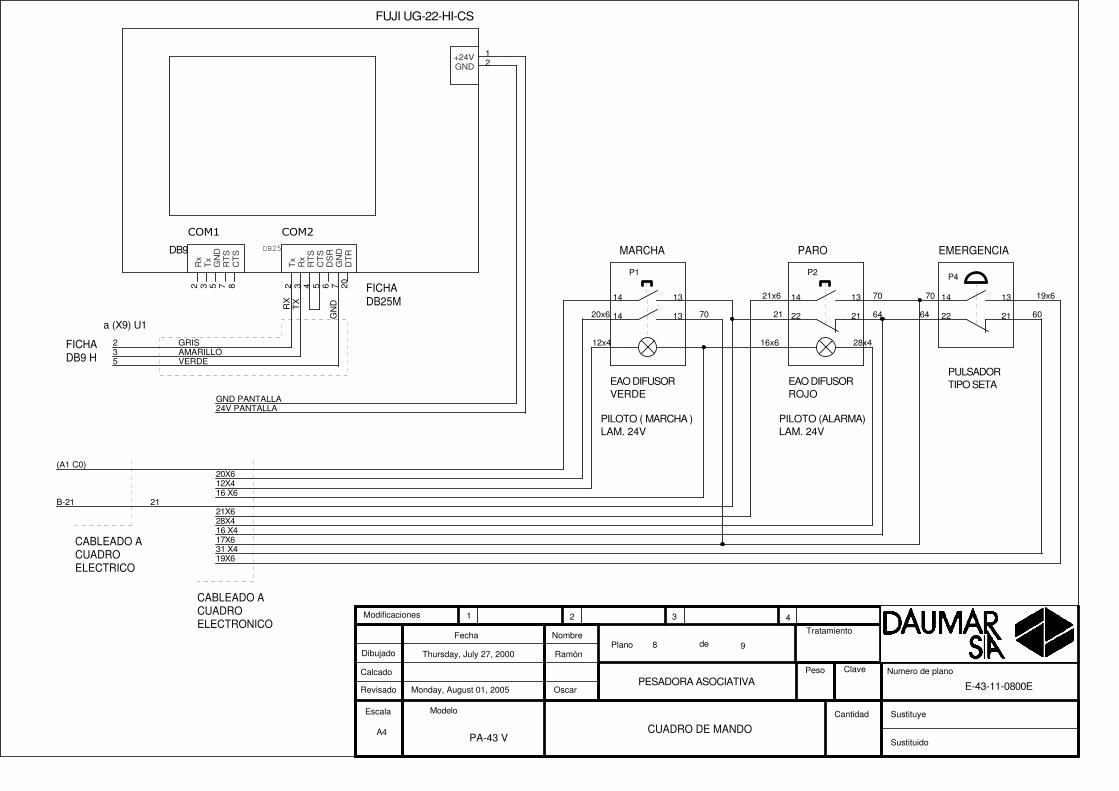
CABLEADO ACUADROELECTRONICO
EMERGENCIA
PULSADORTIPO SETA
PARO
EAO DIFUSORVERDE
PILOTO ( MARCHA )LAM. 24V
MARCHA
EAO DIFUSORROJO
FICHADB25M
a (X9) U1
PILOTO (ALARMA)LAM. 24V
FICHADB9 H
CABLEADO ACUADROELECTRICO
A4
Monday, August 01, 2005
CUADRO DE MANDO
Thursday, July 27, 2000
PA-43 V
E-43-11-0800E
Ramón
OscarPESADORA ASOCIATIVA
98
Escala
Plano deDibujado
Calcado
Revisado
Fecha Nombre
Modelo
Sustituido
Sustituye
Tratamiento
Peso Clave
1 2 3 4
Cantidad
Modificaciones
Numero de plano
GRIS2
31 X4
21X6
19X6
19x6
28X4
60
17X6
21x6
VERDE5
B-21 21
28x4
16 X4
21 646470
12X420X6
12x4
20x6
(A1 C0)
RX
GN
D
AMARILLO3
TX
24V PANTALLAGND PANTALLA
16 X6
16x6
70 70
P2
1314
P1
1314
2122 21221314
P4
1314
���� ����
DB9 DB25
FUJI UG-22-HI-CS
12
2 3 85 7 2 3 4 5 76 20
+24VGND
Rx
Tx
CT
S
GN
DR
TS
Tx
Rx
RT
SC
TS
GN
DD
SR
DT
R
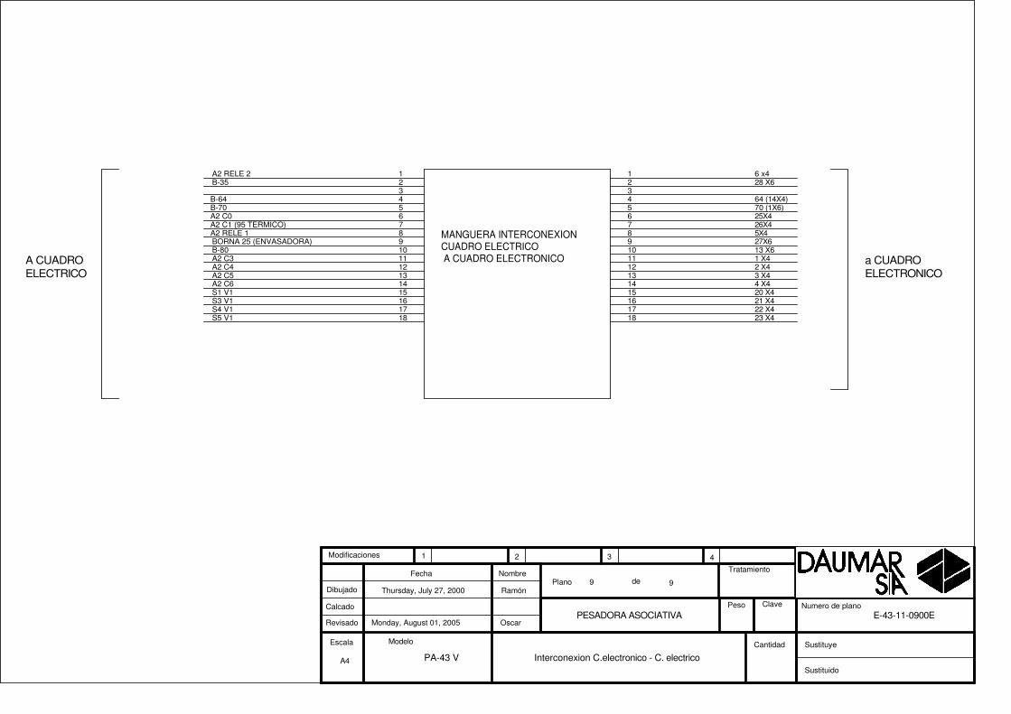
MANGUERA INTERCONEXIONCUADRO ELECTRICO A CUADRO ELECTRONICO a CUADRO
ELECTRONICOA CUADROELECTRICO
A4
Monday, August 01, 2005
Interconexion C.electronico - C. electrico
Thursday, July 27, 2000
PA-43 V
E-43-11-0900E
Ramón
OscarPESADORA ASOCIATIVA
99
Escala
Plano deDibujado
Calcado
Revisado
Fecha Nombre
Modelo
Sustituido
Sustituye
Tratamiento
Peso Clave
1 2 3 4
Cantidad
Modificaciones
Numero de plano
1 6 x4
9 27X610 13 X6
14 4 X4
8 5X4
15 20 X4
11 1 X412 2 X4
4 64 (14X4)
13 3 X4
3
7 26X4
5 70 (1X6)6 25X4
2 28 X61A2 RELE 2
9BORNA 25 (ENVASADORA)10B-80
14A2 C6
8A2 RELE 1
15S1 V1
11A2 C312A2 C4
4B-64
13A2 C5
3
7A2 C1 (95 TERMICO)
5B-706A2 C0
2B-35
16 21 X417 22 X418 23 X4
16S3 V117S4 V118S5 V1

X4
X6
X3
X1
SALIDAS
EN
TR
AD
AS
TRAFO
BUS I/O
117
1632
171
1632
1
8
X 2
X 8
X11
X 1
TRAFO
RS-232COM 1
CEL.CARGA
CEL.CARGA
BUS I/O1
5
1
8
1 5
CI-9030-A CI-9092
X5 SALIDAS
161
X 9
1
9
X 10
1
9
X12
1 5
X13
1 5
CEL.CARGA
RS-232COM 2
( SIN USO ) ( SIN USO )
TR
AF
OT
-511
BA
SE
SC
HU
KO
BUCLECORRIENTE
(MACHO)
(MACHO)
(MACHO)
FU
EN
TE
ALI
ME
NT
AC
ION
S8V
S-0
3024
A3
Monday, August 01, 2005
SITUACION CONECTORES
Friday, May 28, 1999
PA-43 V
E-43-11-1000E
Ramón
Oscar
CARTAS ELECTRONICAS
11
Escala
Plano deDibujado
Calcado
Revisado
Fecha Nombre
Modelo
Sustituido
Sustituye
Tratamiento
Peso Clave
1 2 3 4
Cantidad
Modificaciones
Numero de plano