Embed Size (px)
Citation preview
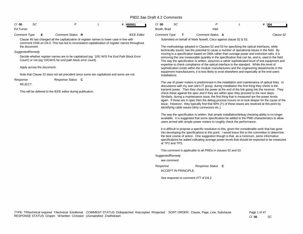
P802.3ae Draft 4.2 Comments
# 450001Cl 00 SC P L
Comment Type EClause 45 has changed all the capitalization of register names to lower case in line with comment #336 on D4.0. This has led to inconsistent capitalization of register names throughout the document.
SuggestedRemedyDecide whether register names are to be capitalized (eg '10G WIS Far End Path Block Error Count') or not (eg '10GWIS far end path block error count).
Apply across the document.
Note that Clause 22 does not set precident since some are capitalized and some are not.
ResponseREJECT.
This will be defered to the IEEE editor during publication.
Comment Status R
Response Status C
IEEE Editor
Ed Turner# 304Cl 00 SC P L
Comment Type TSubmitted on behalf of Mark Nowell, Cisco against clause 52 & 53.
The methodology adopted in Clauses 52 and 53 for specifying the optical interfaces, while technically sound, has the potential to cause a number of operational issues in the field. By moving to a specification based on OMA rather than average power and extinction ratio, it is removing the one measurable quantity in the specification that can be, and is, used in the field. The way the specification is written, assumes a rather sophisticated level of test equipment and expertise to check compliance of the optical interface to the standard. While this level of sophistication exists within the module manufacturers and the engineering departments in the equipment manufacturers, it is less likely to exist elsewhere and especially at the end-users installations.
The use of power meters is predominant in the installation and maintenance of optical links. In discussions with my own site's IT group, during installation the first thing they check is the transmit power. Then they check the power at the end of the link going into the receiver. They check these against the spec and if they are within spec they proceed to the next steps. Similarly, during a maintenance issue, the first thing that is measured are the power levels again. If those are in spec then the debug process moves on to look deeper for the cause of the issue. However, they typically find that 90% (!!) of these issues are resolved at this point by identifying cable issues (dirty connectors etc.).
The way the specification is written, that simple installation/debug checking ability is no longer available. It is suggested that some specification be added to the PMD characteristics to allow users armed with simple power meters to roughly check the performance.
It is difficult to propose a specific resolution to this, given the considerable work that has gone into developing the specifications to this point. I would leave this to the committee to determine the best course of action. One suggestion though is that, as a minimum, some informative specifications be added indicating average power levels that should be expected to be measured at TP2 and TP3.
This comment is applicable to all PMDs in clauses 52 and 53.
SuggestedRemedysee comment
ResponseACCEPT IN PRINCIPLE.
See response to comment #77 of D4.2.
Comment Status A
Response Status C
Clause 52
Booth, Brad Intel
TYPE: TR/technical required T/technical E/editorial COMMENT STATUS: D/dispatched A/accepted R/rejected SORT ORDER: Clause, Page, Line, SubclauseRESPONSE STATUS: O/open W/written C/closed U/unsatisfied Z/withdrawn Cl 00 SC
Page 1 of 47
P802.3ae Draft 4.2 Comments
# 303Cl 00 SC 45.2.1.7.5 P L
Comment Type E45.2.1.7.5 Receive fault (1.8.10) says"When read as a one, bit 1.8.10 indicates that the PMA/PMD has detected a fault condition on the receive path."while52.4.9 PMD_receive_fault function says: "... mapped to the PMD_receive_fault bit as specified in 45.2.1.7.5."
SuggestedRemedyI don't think these are compatible. Either it's PMA/PMD receive fault or it's PMD receive fault (whatever either means). If the former, "mapped to" is too strong: "contributes to" would be better.
ResponseACCEPT.
This comment is against clause 52.Change 52.4.9 PMD_receive_fault function to read: "... contributes to the PMA/PMD receive fault bit as specified in 45.2.1.7.5."
Comment Status A
Response Status C
Clause 52
Dawe, Piers Agilent
# 301Cl 00 SC 52.14.4 P 487 L 34
Comment Type EWe still have some normative references tostandards that we haven't added to 1.3 Normative references. See the page above for examples.
SuggestedRemedyReview the draft to for normative references to standards not in the current 1.3 and add to 1.3.
ResponseACCEPT.
Verify all references in Clause 52. Highlight references that need to be added to 1.3 to Editor-in-Chief.
Comment Status A
Response Status C
Clause 52
Thaler, Pat Agilent
# 106Cl 00 SC 52.4.9 P 458 L 6
Comment Type TRThis appears to be a change without a mandate, nor, as far as I can understand it, a good reason. The change does not enable something which was previously forbidden but it excludes something which was previously allowed, and which makes sense.
A long time ago when we generated the "Tom Alexander" diagram (now Figure 44A-7) we had an agreement that hard-wired instantaneous signals such as PMA_Signal.indicate going up the layer stack would carry a one-bit summary of several bits of information beneath, while the information going out of the side of the stack, to the station management via the MDIO, would be unadulterated so that the station management systems, or humans, could diagnose the situation. But at the last meeting, text in 52.4.6 PMD_fault function was changed from "The faults detected by this function are implementation specific." to "PMD_receive_fault is the logical OR of NOT�SIGNAL_DETECT and any implementation specific fault." Neither D4.0 comment #270 nor D4.1 comment #88 justifies this change. D4.0 comment #270 does not apply - apart from to the names - it is addressing the signalling up the stack, as referred to above. There is no mandate for this change.
Equally importantly, customers may not want to do it this way. Now a user who finds a PMD_receive_fault register asserted needs to find a known good optical signal to apply to his PMD before he knows whether to take any notice of it. The "OR logic" is destroying information; the PMD signal detect is already in its own MDIO register. Much diagnostics is outside the scope of the standard, but obstructing diagnostics should be too.
This is an area where more flexibility is better - look at the range of alarm-masks and so on in the MSAs. We can let implementers and users go with their own preferences. Especially when we are trying to close this standard, we should not make unwarranted changes.
SuggestedRemedyRevert to previous sentence: "The faults detected by this function are implementation specific." And, add "The status of SIGNAL_DETECT may or may not be taken into account."
ResponseREJECT.
The fault bit in status 1 (1.1.7) includes all fault indications including signal detect. The logical OR is not destroying information. If the fault bit is asserted and the signal detect (1.9.0) is not, then there is another fault within the PMA/PMD and vendor specific registers can be used to provide implementation specific information related to the other fault. If the fault bit and the signal detect bit are asserted, then the fault is with the reception of the signal which is considered the critical fault in this situation. All other faults in this situation are implementation specific.
This issue was debated extensively in St. Louis, and the task force accepted this resolution. Furthermore, your TR comment with this change in the response was re-circulated and there have been no other comments submitted against this change.
Vote:
Comment Status R
Response Status C
Clause 52
Dawe, Piers Agilent
TYPE: TR/technical required T/technical E/editorial COMMENT STATUS: D/dispatched A/accepted R/rejected SORT ORDER: Clause, Page, Line, SubclauseRESPONSE STATUS: O/open W/written C/closed U/unsatisfied Z/withdrawn Cl 00 SC 52.4.9
Page 2 of 47
P802.3ae Draft 4.2 CommentsY: 8 N: 1
# 300Cl 00 SC 52.9.1.1 P 468 L 44
Comment Type TRIf our plan is for the next recirculation ballot to be the last, then editor's notes such as this one which imply that we believe we aren't done yet. Also, a number of editor's notes don't contain the normal full heading for editor's notes: "Editor's note: To be removed prior to final publication." so there is a risk that this note will stay in if we approve the standard with it there. This comment also applies to the following editor's notes: 52.9.8 page 475 (TR on this note as it indicates we intend to potentially make a substantive change and we need to have finished such changes to be done), 52.14.2.1 page 486, 52.14.4 page 487 (TR on this note as it indicates we have a normative reference to things that we don't expect to be standards at the time of publicaiton).
SuggestedRemedyDelete the notes or at a minimum add "To be removed prior to final publication. For the note at 52.14.2.1, either delete the text that it says should be removed before publication or move the text to the editor's note in place of the current note text." For note at 52.14.4, verify whether we can have a normative requirement to meet an existing standard or future standards and add the standards/pre-standards here to 1.3.
ResponseACCEPT.
Editor-in-Chief to ensure all editor's notes conform or are removed.
Comment Status A
Response Status C
Thaler, Pat Agilent
# 302Cl 00 SC 52-14 P Tables 52.2 L
Comment Type EIn regard to ease of use, it is very hard to find the exact type of fiber and specific attenuator recommended to achieve the 40 km objective. Table 52.24 has a foot note which points to Table 52.24 which has a foot note that points to clause 52.14.3 which points to a figure 52-15 on attenuator management.
SuggestedRemedyPlease make specific recommendation (s) in one location about SM fiber cable type and attenuators needed to achieve 40 km objective. Please state something more specific than that the fiber needs to be better than B1.1 or B1.3
ResponseREJECT.
The information required to build a 40 km link is available. As in footnote a for Table 52-15, the attenuation on the 40 km link needs to be better than the attenuation on B1.1 and B1.3 single-mode fiber. The attenuation of these engineered links needs to be managed to comply with attenuation requirements specified in 52.14.3. If very low attenuation fiber is used, the link may require insertion of attenuators to be compliant with 52.14.3.
Comment Status R
Response Status C
Bruce Tolley CIsco
# 140Cl 00 SC All P L
Comment Type EWhen I wrote my comments # 81-83 to D4.1, I was expecting that each PICS would be self contained. Hence if an interface was used by two clauses, there would be similar PICS for each clause. I pointed at XSBI but the point is more general. I was told that it doesn't work that way. However, this is not obvious to the reader; the chain of cross-references is very weak and easily overlooked. But there is an easy fix: refer to one PICS table from another. For example, 50.6.3 has an optional *XSBI, similarly 49.3.3 . Each of these can refer to 51.10 as well as 50.3.6 and 49.1.5.
SuggestedRemedyOnce per "borrowed" interface per clause, refer to the PICS master for that interface.
By the way 51.10.3 should have *XSBI - note the *.
ResponseACCEPT IN PRINCIPLE.
The use of asterisks should comply with 21.6.6. Asterisk is required by each item whose reference is used in a conditional symbol.
Make the following changes in Clause 46:- 46.5.2.3, delete item B, deleted item *XS, add * to RS, and rename *EL to *XGE- Change status to place the following items in the PHY package: G1, FS10, FS11, FS12; and update the support fields to include N/A[ ]- Change status to place the following items in the RS package: G2, PL1-13, DS1-4, FS3, FS5, FS7, FS14, FS16-17, LF1-5; and update the support fields to include N/A[ ]- Change status to place the following items in the XGE package: FS1-2, FS4, FS6, FS8-9, FS13, FS15, EC1-4; and update the support fields to include N/A[ ]- Change text in 46.3.2.3 on line 5 from "encoded" to "decoded by the RS"- Add the following note after 46.5.3.4 heading: "NOTE - An XGXS adjacent to an RS exhibits the characteristics of a PHY for the items in this subclause, and an XGXS adjacent to a PCS exhibits the characteristics of an RS for the items in this subclause."
Make the following change to Clause 47 (47.6.3):- change *XGM entry to be: "XGE; XGMII compatibility interface; 46, 47.1.4; Compatibility interface is supported; O; Yes[ ] No[ ]"- add "45" to subclause reference for MD item
Make the following change to Clause 48 (48.7.3):- change MD item feature to be "MDIO" and subclause to be "45, 48.1.3.1"- change XGXS item subclause to be "47, 48.1.5"- change XGMII item to be "XGE" and the subclause to be "46, 48.1.3.1"- change LX4 item subclause to be "53, 48.1.3.3"
Make the following change to Clause 49:- in 49.3.3, change items "*XSBI", "*XGM", "*MD", "*PMA" to read "XSBI", "XGE", "MD", "PMA" respectively- in 49.3.5, change item "JT5" to read "*JT5"
Comment Status A
Response Status C
Dawe, Piers Agilent
TYPE: TR/technical required T/technical E/editorial COMMENT STATUS: D/dispatched A/accepted R/rejected SORT ORDER: Clause, Page, Line, SubclauseRESPONSE STATUS: O/open W/written C/closed U/unsatisfied Z/withdrawn Cl 00 SC All
Page 3 of 47
P802.3ae Draft 4.2 Comments
Make the following change to Clause 50 (50.6.3):- change item *XSBI to be "XSBI ; XSBI compatibility interface; 51, 50.3.6; Compatibility interface is supported; O; Yes[ ] No[ ]"
Make the following change to Clause 51:- in 51.10.3, change "XSBI" to "*XSBI"
Make the following change to Clause 52:- in 52.15.4.1, change FS7 status from "MDIO:M" to "MD:M"
Make the following change to Clause 53:- in 53.15.3, remove asterisks from the following items: LX4, OFP, TP1, TP4 and DC; change *MDIO to *MD- in 53.15.4.1, change MDIO:O in FN11 and FN12 to be MD:O- in 53.15.4.3, change O:MDIO to be MD:M in MR1, and MD:O in MR2, MR3, MR5, MR6 and MR7
# 96Cl 00 SC Table 51-12 P 444 L 6
Comment Type TRComments #99046 and #99048 of D4.1 (formerly comments #11 and #12, respectively, of D4.0) state that the +/- 100 ppm clock tolerance currently specified for the 10GBASE-LW and 10GBASE-EW receivers (in Tables 52-14 and 52-18, respectively) is more than is required in relation to the transmitter specification and any possible transport network such as SDH/SONET, OTN, and also old legacy 10 G WDM transponder equipment. Both comments indicate that, as such, the specification is internally inconsistent and also inconsistent with respect to transport equipment. There is no reason to require the receiver to have a tolerance of +/- 100 ppm because no received signal will ever have a frequency offset greater than +/- 20 ppm. The comments state that the receiver specification should be changed to what is required in line with the transmitter and transport network specification.The response to these comments was REJECT, with a reference to the comment #93 response; this response simply indicated that this is consistent with clauses 46-51, and would be a flip-flop after much discussion to set the receiver tolerance to +/- 100 ppm.This response does not address the technical issue raised in the comments. The fact is that the +/- 100 ppm receiver tolerance is much more stringent than is needed for the +/- 20 ppm transmit tolerance spec.The suggested remedy in both comments #99046 and #99048, to change the required receiver tolerance to +/- 20 ppm, would result in a less costly receiver design that would work with the transmitter specification. The design would be less costly because the receiver clock tolerance is essentially a spec on the receiver phase-locked loop pull-in range; making the pull-in range unnecessarily large results in the design being more costly than it needs to be.This issue was discussed in the March 26, 2002 serial PMD call. The commenter raised the issue there because the comments were against clause 52, and they were against clause 52 because the relevant tables that contain the receiver clock tolerance (Tables 52-14 and 52-18) are in clause 52. Nonetheless, the members of the serial PMD group on the call said that the optics group does not really have the expertise or the strong opinions on this matter, and this would be better raised as a comment against “clause 00” for discussion in the larger group. Therefore, the present comment is against “clause 00”.It also was stated in the March 26, 2002 seial PMD call that changing the receiver clock tolerance to +/- 20 ppm would also require changes to clause 51. Examination of clause 51 does indicate that receiver clock tolerance is also given in Table 51-12. The present comment indicates that the entry for 10GBASE-W in Table 51-12 on Line 6, p. 444, should be changed from 622.08 MHz+/-100ppm to 622.08 MHz+/-20ppm.This is in addition to the changes to Clause 52, Tables 52-14 and 52-18 already indicated in Comments #99046 and #99048. Finally, note that the original comment that gave rise to the change to the WAN PHY transmit clock tolerance, comment #661 of D3.0, indicated that the 622.08 MHz+/-100ppm in what was then Table 51.6 of D3.0 should be changed to 622.08 MHz+/-20ppm, and that analogous changes should be made to Tables 52-7, 52-9, 52-12, 52-14, 52-17, and 52-18. The clause 52 tables include the transmit and receive specs. The clause 51 table pertains only to the transmit spec; however, D3.0 did not have a clause analogous to Clause 51.7.2 in D4.2, nor a Table analogous to Table 51-12 in D4.2. The statements in Comment #661 of D3.0 at least indicate that the intent of this comment was to change both the 10GBASE-W transmitter and receiver clock tolerances from +/-100ppm to +/-20ppm. The response to this comment indicates ACCEPT, with the comment re-issued as #44000 and 44001 to permit clause 51 and 52 editors to track closure of the comment.
SuggestedRemedy
Comment Status R comment 96
Geoffrey Garner Lucent Technologies
TYPE: TR/technical required T/technical E/editorial COMMENT STATUS: D/dispatched A/accepted R/rejected SORT ORDER: Clause, Page, Line, SubclauseRESPONSE STATUS: O/open W/written C/closed U/unsatisfied Z/withdrawn Cl 00 SC Table 51-12
Page 4 of 47
P802.3ae Draft 4.2 CommentsMake the changes to Tables 52-14 and 52-18 already indicated in Comments #99046 and #99048, to change the 10GBASE-LW and EW receiver specs to +/-20ppm. Change 622.08 MHz+/-100ppm to 622.08 MHz+/-20ppm in Table 51-12.
ResponseREJECT.
This comment has been ruled as not a new comment. This comment was submitted against Clause 52 in D4.0 by the commenter, and the comment was rejected. The comment was recirculated and the draft has remained approved through the D4.1 and D4.2 recirculations.
Input from other PLL designers is that +/- 100 ppm doesn't impact the cost of the PLL design. The assumption that +/- 20 ppm would always occur at the receiver is invalid. One possible application for increased receive clock tolerance is the mapping and demapping of 10GBASE-W into a SONET/SDH payload.
Historically, Ethernet has been liberal on what they receive and conservative on what they transmit. The support for the current tolerances is indicative of support for this philosophy.
Response Status W
# 156Cl 01 SC 1.3 P 4 L 51
Comment Type TRDelete the refernece on to INCITS T11 Project 1413-D. One can not have a normative reference to a project and we do not reference that project normatively in the body of the standard.
SuggestedRemedyEither delete the reference (my preference as the information is too transitory to put into a standard - the group is expected to finish that project within months of when we finish ours so the reference could be out of date before we are published) or move it to Annex A (informative) Additional references.
ResponseACCEPT IN PRINCIPLE.
The reference will deleted.
Comment Status A
Response Status C
Thaler, Pat Agilent
# 78Cl 01 SC 1.4 P L
Comment Type ENeed a definition of primitive for the glossary (comment D4.1 #62 refers). This seems to be a computer science term; is it defined in the ISO OSI seven layer material? Or in a computer science textbook? If no-one can help, here's my suggestion:
SuggestedRemedy"Service primitives are described in 1.2.2."
ResponseREJECT.
This is beyond the scope of this recirculation ballot. The task force recommends that the commenter submit a maintenance request.
Comment Status R
Response Status C
Dawe, Piers Agilent
# 5Cl 01 SC 45.2.3.6 P 198 L 18
Comment Type EFirst occurance of PRBS31 is not defined
SuggestedRemedyDefine PRBS31 in section 1.5PRBS31 = 2 147 483 647-bit pseudo-random test sequence as defined by (ITU O.150 | Section 49.2.8)
ResponseACCEPT IN PRINCIPLE.
Add a refernce to subclause 49.2.8 in the first mention of PRBS31 in Clause 45 as follows -
In subclause 45.2.2.6.1 'PRBS31 receive test pattern enable (2.7.5)' change the text '.. the optional PRBS31 pattern testing ..' to read '.. the optional PRBS31 (see 49.2.8) pattern testing ..'.
Comment Status A
Response Status C
Tim Warland Quake Technologies
TYPE: TR/technical required T/technical E/editorial COMMENT STATUS: D/dispatched A/accepted R/rejected SORT ORDER: Clause, Page, Line, SubclauseRESPONSE STATUS: O/open W/written C/closed U/unsatisfied Z/withdrawn Cl 01 SC 45.2.3.6
Page 5 of 47

P802.3ae Draft 4.2 Comments
# 98Cl 30 SC 30.5.1.1.4 P 60 L 25
Comment Type TThis comment is being submitted on behalf of C. M. Heard.
Gentlemen,
In the behaviour clause of aMediaAvailable (subclause 30.5.1.1.4), all of the referenced Clause 45 MDIO register bits have latching behaviour except for the 10GBASE-R PCS high BER status bit (45.2.3.11.3). Was this intended? There does exist a latching version of this bit— the 10GBASE-R PCS latched high BER status bit (45.2.3.12.2). In at least one other case a latching status bit— the PHY XS transmit link status bit (45.2.4.2.2) -- was selected over an equivalent non-latching status bit— namely the PHY XGXS transmit lane alignment status bit (45.2.4.8.1).
SuggestedRemedySent by:“C. M. Heard” <[email protected]> To:Dan Romascanu <[email protected]>, David Law/GB/3Com@3Comcc: Subject:Was reference in 30.5.1.1.4 to non-latching MDIO intended?
Gentlemen,In the behaviour clause of aMediaAvailable (subclause 30.5.1.1.4), all of the referenced Clause 45 MDIO register bits have latching behaviour except for the 10GBASE-R PCS high BER status bit (45.2.3.11.3). Was this intended? There does exist a latching version of this bit— the 10GBASE-R PCS latched high BER status bit (45.2.3.12.2). In at least one other case a latching status bit— the PHY XS transmit link status bit (45.2.4.2.2) -- was selected over an equivalent non-latching status bit— namely the PHY XGXS transmit lane alignment status bit (45.2.4.8.1).In case you think that it is desirable to change the reference to the latching status bit I have indicated below the changes to the text that would do this. There are also some places in the surrounding text where I have changed the capitalization to match Clause 45.Where a Clause 45 MDIO interface is present a logic zero in thePMA/PMD Receive link status bit (45.2.1.2.2) maps to the ^^^^^^^receiveenumeration “PMD link fault”, a logic one in the LOF status bit(45.2.2.10.4) maps to the enumeration “WIS frame loss”, a logicone in the LOS status bit (45.2.2.10.5) maps to the enumeration“WIS signal loss”, a logic zero in the PCS Receive link status ^^^^^^^receivebit (45.2.3.2.2) maps to the enumeration “PCS link fault”, a logic one in the 10GBASE-R PCS high BER status bit (45.2.3.11.3) ^^^^^^^^^^^^^^^^^^^^^^^^^^^^^^^^^latched high BER status bit (45.2.3.12.2)maps to the enmeration “excessive BER”, a logic zero in the DTE XS receive link status bit (45.2.5.2.2) maps to the enmeration “DXS link fault” and a logic zero in the PHY XS transmit
Comment Status A
David Law 3Com
link status bit (45.2.4.2.2) maps to the enmeration “PXS link fault”.
ResponseACCEPT IN PRINCIPLE.
This is a duplicate of comment 99.
Response Status C
# 99Cl 30 SC 30.5.1.1.4 P 60 L 25
Comment Type TThis comment is being submitted on behalf of C. M. Heard.
Gentlemen,
In the behaviour clause of aMediaAvailable (subclause 30.5.1.1.4), all of the referenced Clause 45 MDIO register bits have latching behaviour except for the 10GBASE-R PCS high BER status bit (45.2.3.11.3). Was this intended? There does exist a latching version of this bit— the 10GBASE-R PCS latched high BER status bit (45.2.3.12.2). In at least one other case a latching status bit— the PHY XS transmit link status bit (45.2.4.2.2) -- was selected over an equivalent non-latching status bit— namely the PHY XGXS transmit lane alignment status bit (45.2.4.8.1).
SuggestedRemedyIn case you think that it is desirable to change the reference to the latching status bit I have indicated below the changes to the text that would do this. There are also some places in the surrounding text where I have changed the capitalization to match Clause 45.Where a Clause 45 MDIO interface is present a logic zero in thePMA/PMD Receive link status bit (45.2.1.2.2) maps to the ^^^^^^^receiveenumeration “PMD link fault”, a logic one in the LOF status bit(45.2.2.10.4) maps to the enumeration “WIS frame loss”, a logicone in the LOS status bit (45.2.2.10.5) maps to the enumeration“WIS signal loss”, a logic zero in the PCS Receive link status ^^^^^^^receivebit (45.2.3.2.2) maps to the enumeration “PCS link fault”, a logic one in the 10GBASE-R PCS high BER status bit (45.2.3.11.3) ^^^^^^^^^^^^^^^^^^^^^^^^^^^^^^^^^latched high BER status bit (45.2.3.12.2)maps to the enmeration “excessive BER”, a logic zero in the DTE XS receive link status bit (45.2.5.2.2) maps to the enmeration “DXS link fault” and a logic zero in the PHY XS transmit link status bit (45.2.4.2.2) maps to the enmeration “PXS link fault”.
ResponseACCEPT IN PRINCIPLE.
Accept that the reference should be changed to latched version of the register bit. As noted latching bits are used in prefernce to equivalent non-latching bit where avalible.
The capitalization issues is deferred to comment #450001.
Comment Status A
Response Status C
David Law 3Com
TYPE: TR/technical required T/technical E/editorial COMMENT STATUS: D/dispatched A/accepted R/rejected SORT ORDER: Clause, Page, Line, SubclauseRESPONSE STATUS: O/open W/written C/closed U/unsatisfied Z/withdrawn Cl 30 SC 30.5.1.1.4
Page 6 of 47
P802.3ae Draft 4.2 Comments
# 97Cl 30 SC 30.8.1.1.2 P 62 L 35
Comment Type TThe following is submitted on behalf of C. M. Heard.
In reviewing the changes in Clause 30 in P802.3ae/D4.2 some things caught my eye which up to now I had not noticed. Specifically, aJ0ValueTX, aJ0ValueRX, aJ1ValueTX, and aJ1ValueRX are all described as fixed-length 16 octet values in Clause 30, but the formal SYNTAX— given via the type definition JValue in 30B.2 -- allows an octet string of variable length from 0 to 15 octets. Similarly, aSectionStatus, aLineStatus, aPathStatus, and aFarEndPathStatus are all described as fixed length bit strings in Clause 30, but the formal SYNTAX allows a variable-length string. In order for the SYNTAX and BEHAVIOUR clauses to match, it would seem that the SYNTAX for all of these objects should be changed to indicate that they have fixed length. The affected subclauses are 30.8.1.1.2, 30.8.1.1.10, 30.8.1.1.18, 30.8.1.1.25, and 30B.2 (30.A.15.2 is not affected since it references the type definitions in 30B.2). Specific suggestions for changes are noted below. Please note: even if variable lengths were intended for the status objects, the maximum size for aFarEndPathStatus (30.8.1.1.25) is 2 while that for FarEndPathStatus (30B.2) is 8.Regards,Mike Heard
SuggestedRemedy30.8.1.1.2 aSectionStatusATTRIBUTEAPPROPRIATE SYNTAX:BIT STRING [SIZE (1..2)] <<<< should be (SIZE (2))BEHAVIOUR DEFINED AS:A string of 2 bits corresponding to the Section Status (50.3.2.5). The first bit corresponds to the Loss of Signal flag and maps to the LOS bit in the WIS Status 3 register. The second bit corresponds to the Loss of Frame flagand maps to the LOF bit in the WIS Status 3 register. If a Clause 45 MDIO Interface to the WIS is present, then this will map to the WIS Status 3 register specified in 45.2.2.10.;
30.8.1.1.10 aLineStatusATTRIBUTEAPPROPRIATE SYNTAX:BIT STRING [SIZE (1..2)] <<<< should be (SIZE (2))BEHAVIOUR DEFINED AS:A string of 2 bits reflectingthe Line status (50.3.2.5). The first bit corresponds to the Line Alarm Indication Signal flag and maps to the AIS-L bit. The second bit corresponds to the Line Remote Defect Indication flag and maps to the RDI-L bit. If a Clause 45 MDIO Interface to the WIS is present, then this will map to the WIS Status 3 register specified in 45.2.2.10;
30.8.1.1.18 aPathStatusATTRIBUTEAPPROPRIATE SYNTAX:BIT STRING [SIZE (1..4)] <<<< should be (SIZE (4))BEHAVIOUR DEFINED AS:A string of 4 bits corresponding to the Path Status (50.3.2.5). The first bit corresponds to the Loss of Pointer flag and maps to the LOP-P bit, the second bit corresponds to the Alarm Indication Signal and maps to the AIS-P bit, the third bit corresponds to the Path Label
Comment Status A
David Law 3Com
Mismatch flagand maps to the PLM-P bit and the fourth bit corresponds to the Path Loss of Cell Delineation flagand maps to the LCD-P bit. If a Clause 45 MDIO Interface to the WIS is present, then this will map to the WIS Status 3 register specified in 45.2.2.10;
30.8.1.1.25 aFarEndPathStatusATTRIBUTEAPPROPRIATE SYNTAX:BIT STRING [SIZE (1..2)] <<<< should be (SIZE (2))BEHAVIOUR DEFINED AS:A string of 2 bits corresponding to the Far End Path Status (50.3.2.5). The first bit corresponds to the Far End Path Label Mismatch/Path Loss of Cell Delineation flag and maps to the Far End PLM-P/LCD-P bit, and the second bit corresponds to the Far End Path Alarm Indication Signal/Path Loss of Pointer flag and maps to the Far End AIS-P/LOP-P bit. If a Clause 45 MDIO Interface to the WIS is present, then this will map to the WIS Status 3 register specified in 45.2.2.10;
30B.2 ASN.1 module for CSMA/CD managed objectsJValue::= OCTET STRING (SIZE (0..15)) <<<< should be (SIZE (16))
LineStatus ::= BIT STRING (SIZE (1..2)) <<<< should be (SIZE (2))
FarEndPathStatus ::= BIT STRING (SIZE (1..8)) <<<< should be (SIZE (2))PathStatus ::= BIT STRING (SIZE (1..4)) <<<< should be (SIZE (4))
SectionStatus ::= BIT STRING (SIZE (1..2)) <<<< should be (SIZE (2))
P.S. The above assumes that the “APPROPRIATE SYNTAX” in Clause 30 is not required to be a valid ASN.1 type. If it is, then the phrase “OCTET STRING, 0 - 15” in subclauses 30.8.1.1.8 (aJ0ValueTX), 30.8.1.1.9 (aJ0ValueRX), 30.8.1.1.23 (aJ1ValueTX), and 30.8.1.1.24 (aJ1ValueRX) needs to be changed to “OCTET STRING (SIZE (16))”.
ResponseACCEPT IN PRINCIPLE.
While the 'APPROPRIATE SYNTAX' in Clause 30 is based on ASN.1 it is not required to be a valid ASN.1 type. For an existing BIT STRING example see 30.7.2.1.20 aAggPortActorAdminState, for an existing OCTET STRING example see 30.4.1.1.7 aRepeaterHealthData.
Hence the Clause 30 changes will be as follows. The Annex 30B.2 changes will be as per the suggested remedy.
30.8.1.1.2 aSectionStatusBIT STRING [SIZE (1..2)] will be changed to read [SIZE (2)]30.8.1.1.10 aLineStatusBIT STRING [SIZE (1..2)] will be changed to read [SIZE (2)]30.8.1.1.18 aPathStatusBIT STRING [SIZE (1..4)] will be changed to read [SIZE (4)]30.8.1.1.25 aFarEndPathStatusBIT STRING [SIZE (1..2)] will be changed to read [SIZE (2)]
Response Status C
TYPE: TR/technical required T/technical E/editorial COMMENT STATUS: D/dispatched A/accepted R/rejected SORT ORDER: Clause, Page, Line, SubclauseRESPONSE STATUS: O/open W/written C/closed U/unsatisfied Z/withdrawn Cl 30 SC 30.8.1.1.2
Page 7 of 47

P802.3ae Draft 4.2 CommentsIn respect to the Post Script comment, while the 'APPROPRIATE SYNTAX' is not required to be a valid ASN.1 type, as the comment has pointed out, 30.8.1.1.8 (aJ0ValueTX), 30.8.1.1.9 (aJ0ValueRX), 30.8.1.1.23 (aJ1ValueTX), and 30.8.1.1.24 (aJ1ValueRX) are fixed rather than variable length. Hence the 'APPROPRIATE SYNTAX' for these attributes will be change to read OCTET STRING, 16.
# 103Cl 30 SC 30.8.1.1.8 P 64 L 1
Comment Type TThe first octet in this value is transmitted first, and the last octet is transmitted last.
SuggestedRemedyPlease clarify.
ResponseACCEPT.
The text will be changed to read -
The first octet of the string is transmitted first, and the last octet is transmitted last.
A similar change needs to be made to 30.8.1.1.23 (aJ1ValueTX). In addition the related text in 30.8.1.1.9 (aJ0ValueRX), and 30.8.1.1.24 (aJ1ValueRX) needs to be changed to read as follows -
The first octet in this string was received first, and the last octet received last.
Comment Status A
Response Status C
David Law 3Com
# 88Cl 30 SC 30.8.1.1.8 P 64 L 13
Comment Type EUse of abbreviations.
SuggestedRemedyOn line 13, change "Tx" to "transmit", and on line 24, change "Rx" to "receive".
On page 67 line 35, change "Tx" to "transmit", and on line 46, change "Rx" to "receive".
ResponseACCEPT.
Comment Status A
Response Status C
Booth, Brad Intel
# 157Cl 44 SC 44.1.4.4 P 164 L 30
Comment Type EPerhaps this is over polishing, but it seems that ", specified in Clauses 48 and 53," would be better following "family of physical layer implementations" because the family rather than the term is specified by those clauses. Similarly for the next two paragraphs.
SuggestedRemedyMove the phrase. However, this is an editorial nit and not at all substantive.
ResponseREJECT.
Comment Status R
Response Status C
Thaler, Pat Agilent
# 158Cl 44A SC 44A.4 P 175 L 10
Comment Type TThis comment addresses labeling issues in the figure. Another comment will address funtional problems. Note that resolution of the other comment may effect some of these labels.
SuggestedRemedyOn line 12, loopback should be PCS loopback.�On line 29, PMD/PMA loopback should be PMA loopback as we do not have PMD loopback.�Also, this picture seems incomplete as it doesn't show the XGXS sublayers.
ResponseACCEPT IN PRINCIPLE.
PMA/PMD Loopback to be changed to PMA loopback.
Comment Status A
Response Status C
Thaler, Pat Agilent
TYPE: TR/technical required T/technical E/editorial COMMENT STATUS: D/dispatched A/accepted R/rejected SORT ORDER: Clause, Page, Line, SubclauseRESPONSE STATUS: O/open W/written C/closed U/unsatisfied Z/withdrawn Cl 44A SC 44A.4
Page 8 of 47
P802.3ae Draft 4.2 Comments
# 161Cl 44A SC 44A.4 P 175 L 12
Comment Type TRThis diagram is not correct. Loopback is generally recommended to cover as much of the sublayer as possible. If it is implemented that way, then error signals generated internal to the sublayer should not be over-ridden. For instance, loopback in the PCS should be using the PCS encoder and decoder. If the decoder state machine cannot obtain lock to the signal out of the encoder, the decoder cannot decode anything and it will have to send up Local Fault. That is the way the receive state machine is defined. Similarly for the WIS internal data valid signals.
SuggestedRemedyMove the OR gate below the AND gate in each sublayer so that it ORs the signal from the layer below and the loopback signal to provide an input to the or gate.
One could also add a statement that says something like "This figure represents an implementation of loopback where loopback is implemented in accordance with the recommendation that it exercises as much of the circuitry in the sublayer as possible. If the loopback is implemented above part of the circuitry in a sublayer then any error signals produced below the loopback point should be ignored during loopback as are any error signals from below the sublayer. For instance, if loopback in a WIS implementation was done above the framer, then error signals from the framer should be OR'ed with loopback.
ResponseACCEPT.
Changed the wording from "error signals" to "data valid signals" as the logic doesn't work if the signal is based upon an error condition.
Comment Status A
Response Status C
Thaler, Pat Agilent
# 53Cl 45 SC P L
Comment Type EIs the information on PMA_SIGNAL.indicate(SIGNAL_OK) the same as 45.2.1.2.2 Receive link status (1.1.2) ?
SuggestedRemedyIf so, add text to clarify e.g. "If implemented, PMA/PMD status 1 register bit 2 (Receive link status) is continuously set to the value of PMA_SIGNAL.indicate (see 45.2.1.2.2)."
If not, add text to clarify.
ResponseACCEPT IN PRINCIPLE.
Insert the following text as the third sentence into 45.2.1.2.2:PMA/PMD receive link is down when PMA_SIGNAL.indicate is FAIL, PMD_SIGNAL.indicate is FAIL, or any implementation specific fault condition is present.
Comment Status A
Response Status C
Clause 52
Dawe, Piers Agilent
# 104Cl 45 SC P 219220 L
Comment Type EPRBS32
SuggestedRemedyPRBS31
ResponseACCEPT.
Comment Status A
Response Status C
Dawe, Piers Agilent
# 89Cl 45 SC 45.2.2.12 P 204 L 5
Comment Type EUse of abbreviation.
SuggestedRemedyChange all instances of "tx" to "transmit" in subclause.
ResponseACCEPT.
Comment Status A
Response Status C
Booth, Brad Intel
# 90Cl 45 SC 45.2.2.13 P 205 L 1
Comment Type EUse of abbreviation.
SuggestedRemedyChange all instances of "rx" to "receive" in subclause.
ResponseACCEPT.
Comment Status A
Response Status C
Booth, Brad Intel
# 91Cl 45 SC 45.2.2.18 P 207 L 40
Comment Type EUse of abbreviations.
SuggestedRemedyChange all instances of "tx" to "transmit" in subclause.
ResponseACCEPT.
Comment Status A
Response Status C
Booth, Brad Intel
TYPE: TR/technical required T/technical E/editorial COMMENT STATUS: D/dispatched A/accepted R/rejected SORT ORDER: Clause, Page, Line, SubclauseRESPONSE STATUS: O/open W/written C/closed U/unsatisfied Z/withdrawn Cl 45 SC 45.2.2.18
Page 9 of 47
P802.3ae Draft 4.2 Comments
# 92Cl 45 SC 45.2.2.19 P 208 L 37
Comment Type EUse of abbreviations.
SuggestedRemedyChange all instances of "rx" to "receive" in subclause.
ResponseACCEPT.
Comment Status A
Response Status C
Booth, Brad Intel
# 3Cl 45 SC 45.2.3.11 P 219 L 4
Comment Type EPRBS32 should be PRBS31
SuggestedRemedyChange PRBS32 to PRBS31
ResponseACCEPT.
Comment Status A
Response Status C
Tim Warland Quake Technologies
# 162Cl 45 SC 45.2.3.11 P 219 L 4
Comment Type EPRBS32 should be PRBS31. Occurs additional places.
SuggestedRemedyDo global search and replace for PRBS32
ResponseACCEPT.
Comment Status A
Response Status C
Thaler, Pat Agilent
# 4Cl 45 SC 45.2.3.12 P 220 L 7
Comment Type EPRBS32 should be PRBS31
SuggestedRemedyChange PRBS32 to PRBS31
ResponseACCEPT.
Comment Status A
Response Status C
Tim Warland Quake Technologies
# 48Cl 45 SC 45.2.3.12.2 P 220 L 38
Comment Type EText for 'Latched high BER bit (3.33.14)' incorrectly reads 'When read as a one, bit 3.32.14 ..'
SuggestedRemedyChange to '3.33.14'
ResponseACCEPT.
Comment Status A
Response Status C
Turner, Ed Lattice Semiconductor
# 143Cl 45 SC 45.2.3.16 P 223 L 49
Comment Type EI don't think the test pattern error counter contains the number of errors received during a pattern test. See 49: I think it contains either block errors, or very nearly three times the bit errors when checking PRBS31.
SuggestedRemedyPlease correct if necessary.
ResponseACCEPT IN PRINCIPLE.
Add a second sentence to the last paragraph that reads -
'This counter will count either block errors or bit errors dependent on the test mode (see 49.2.12)'.
Comment Status A
Response Status C
Dawe, Piers Agilent
# 144Cl 45 SC Table 453 P 182 L 24
Comment Type ECan bits with Value always 0, writes ignored be R/W?
SuggestedRemedyRO? Many instances.
ResponseACCEPT IN PRINCIPLE.
Although these bits behave like RO bits we need to keep them defined as R/W since they may be allocated functions in the future. However to clarify this, add in 45.2 a new 4th paragraph that reads as follows -
'To ensure compatibility with future use of reserved bits and registers, the Management Entity should write to reserved bits with a value of 0 and ignore reserved bits on read.'
Comment Status A
Response Status C
Dawe, Piers Agilent
TYPE: TR/technical required T/technical E/editorial COMMENT STATUS: D/dispatched A/accepted R/rejected SORT ORDER: Clause, Page, Line, SubclauseRESPONSE STATUS: O/open W/written C/closed U/unsatisfied Z/withdrawn Cl 45 SC Table 453
Page 10 of 47

P802.3ae Draft 4.2 Comments
# 87Cl 45 SC Table 45-11 P 193 L 40
Comment Type EUse of abbreviations for transmit and receive.
SuggestedRemedyChange "tx" to "transmit" and "rx" to "receive".
ResponseACCEPT.
Comment Status A
Response Status C
Booth, Brad Intel
# 50Cl 45 SC Table 45-6 P 186 L 22
Comment Type TThe 'PMA/PMD present' bit would always be one in the 'PMA/PMD devices in package register' - no matter what package was defined as. Similarly, the 'WIS present' bit would always be one in the WIS devices in package register. And so on for the other MMDs.
SuggestedRemedyChange the 'PMA/PMD present' bit description to 'Value always 1'�Update all the other MMD's devices in package register tables in a similar manner, setting the appropriate 'present' bit for the MMD to always be a one in it's own register.
ResponseREJECT.
Out of scope. The text is adequate.
Comment Status R
Response Status C
Turner, Ed Lattice Semiconductor
# 49Cl 45 SC Table 45-6 P 186 L 6
Comment Type TIn D3.3 an additional vendor specific device was introduced so that there is now a vendor specific MMD 1 at address 30 and a vendor specific MMD 2 at address 31. This table (and others like it in the other MMDs) only has one vendor specific device bit.
SuggestedRemedyChange bit 1.6.15 to 'vendor specific device 2' and add bit 1.6.14 as 'vendor specific device 1' and update all other MMD 'devices in package' register tables.
ResponseACCEPT.
Comment Status A
Response Status C
Turner, Ed Lattice Semiconductor
# 2Cl 46 SC 46 P 276 L 27
Comment Type TRStatement is not complete since IPG can also contain the Sequence ordered set, per Line 33 on same page.
SuggestedRemedychange statement to read:“..Terminate control character,continues with Idle control characters or Sequence ordered set and ends with the Idle control character or the last byte of the sequence ordered set prior to a Start control character.”
ResponseACCEPT IN PRINCIPLE. The comment is not within the scope of the recirulation ballot, but points to an advisable editorial clarification.
The text is correct. Sequence ordered sets are not used in normal interpacket gaps, only when faults are detected and cleared.
Subclause 46.2 and its subparts describe RS transmission of data frames. That is the scope of the normative shall (p.275, l.24). The link fault signaling state machine, either services the transmission of data frames, or in the presence of faults, transmission of sequence ordered sets (46.3.4.3, p.286, l.1-9). The operation of fault detection in PHY sublayers is similar, with either frames or fault signals being serviced.
Line 33 does not say that fault signals are part of <interframe>, but that the signaling logically occurs in the interframe period.
To improve clarity (and reduce the chance of a future interpretation request) add a sentence to the paragraph at line 33 to read:"The signaling of link status information logically occurs in the <inter-frame> period (see 46.3.4). Subclause 46.3.3 describes frame processing when signaling of link status information is initiated or terminated."
Comment Status A
Response Status W
Justin Gaither Xilinx, Inc
# 141Cl 46 SC 46.1.3 P 271 L 38
Comment Type EI think VC-4-64c is payload plus path overhead? Anyway not the full thing that goes on the line. So it can't have a line rate of 9.95328 Gb/s. Many other instances of VC-4-64c may be OK.
SuggestedRemedySTM-64 I think.
ResponseREJECT. A VC-4-64c interface does imply the line rate.
Comment Status R
Response Status C
Dawe, Piers Agilent
TYPE: TR/technical required T/technical E/editorial COMMENT STATUS: D/dispatched A/accepted R/rejected SORT ORDER: Clause, Page, Line, SubclauseRESPONSE STATUS: O/open W/written C/closed U/unsatisfied Z/withdrawn Cl 46 SC 46.1.3
Page 11 of 47
P802.3ae Draft 4.2 Comments
# 99017Cl 47 SC 3.4.5 P 292 L 40
Comment Type TRInput impedance should be specified the same as the output impedance.
SuggestedRemedyChange text similar to the way output impedance is specified.
ResponseREJECT.
Input impedance spec is not considered to be a problem according to test data (working receivers were tested and met spec) supplied that did indicate a valid spec problem with output impedance. Recevier test data indicates that a flat 10 dB input return loss was achievable.
The impact of loosening transmitter return loss as agreed to for D4.0 comment resolutions results in an increase in return loss contribution to deterministic jitter from 0.03 UI to 0.049 UI. The additional impact of loosening receiver return loss as requested by this comment would result in a return loss contribution of 0.072 UI of deterministic jitter. This amount of additional jitter is excessive (blows the jitter budget) in light of the absence of proof of an existing problem with the current input impedance spec.
If evidence is received indicating that the current receiver return loss spec is not acheivable, then other driver and/or receiver parameters must be adjusted in order to maintain a working jitter budget.
Comment Status R
Response Status U
D4.0 #4
Gaither, Justin Xilinx# 84Cl 48 SC 48 P L
Comment Type EIs there a PMA_UNITDATA.indicate primitive in 48? Sometimes it says PMA_UNITDATA.indicate primitive, sometimes SYNC_UNITDATA.indicate message. If it doesn't connect (sub) layers, it's not a primitive. If it were a primitive there would be several short subclauses of (hopefully) boilerplate in the 48.x "functional specifications" subclause. I didn't find it; has clause 48 really got away without having to define any primitives?
SuggestedRemedyMake PMA_UNITDATA.indicate either primitive or message throughout.
Add boilerplate for any primitives not defined elsewhere which cl.48 provides at its service ("upper"?) interface.
ResponseACCEPT IN PRINCIPLE.
PMA_UNITDATA.indicate is specified in 48.3.2.2. PMA_UNITDATA.request is specified in 48.3.2.1. Both are used as primitives throughout Clause 48, which is the correct implementation.
Change "PMD_SIGNAL.indicate message" to "PMD_SIGNAL.indicate primitive" on pg. 325, line 20.
Change "SYNC_UNITDATA.indicate primitive" to "SYNC_UNITDATA.indicate message" at the following locations:- pg. 312, line 50- pg. 313, line 15- pg. 328, line 51
Change "ALIGNED_UNITDATA.indicate primitive" to "ALIGN_UNITDATA.indicate message" at the following locations (note, ALIGNED was altered to ALIGN to match the message definitions):- pg. 313, lines 17 and 23- pg. 330, line 33
Comment Status A
Response Status C
Dawe, Piers Agilent
TYPE: TR/technical required T/technical E/editorial COMMENT STATUS: D/dispatched A/accepted R/rejected SORT ORDER: Clause, Page, Line, SubclauseRESPONSE STATUS: O/open W/written C/closed U/unsatisfied Z/withdrawn Cl 48 SC 48
Page 12 of 47
P802.3ae Draft 4.2 Comments
# 1Cl 48 SC 48 P 316 L 42
Comment Type TRThe polynomial specified in Figure 48-5 does not explicitly dictate a runlength of 128. In general a X^7+x^3+1 polynomial will have a runlength of 127 which will not have an evenly distributed number of R & K, since one will have 63 occurances and the other would have 64 occurances.
SuggestedRemedyAdd a statement saying that the runlength should be equal to 2^7.
ResponseACCEPT IN PRINCIPLE.
The polynomial runlength is 7 by the fact that we have a 7th order polynomial. The sequence length is 127.
Delete "uniformly distributed" from page 316, line 42 to remove the implication that in an infinite length idle that there will be an equal number of Rs and Ks.
The 63/64 ratio is acceptable for reducing spectral peaks.
Comment Status A
Response Status W
Justin Gaither Xilinx, Inc
# 163Cl 48 SC 48.1.1 P 308 L 38
Comment Type TThe new objective isn't clear and it isn't necessary. What is link indication?
SuggestedRemedyPrefer it be deleted because it puts an unnecessary level of detail in this early subclause. If not then change it to �Supports error indication�or�Supports link fault and error indications.
ResponseACCEPT IN PRINCIPLE.
Will change to: Supports link fault and error indications
Comment Status A
Response Status C
Thaler, Pat Agilent
# 7Cl 48 SC 48.1.3.1 P 309 L 40
Comment Type EI am confused by the text “ The PCS interface is the XGMII which provides a uniform interface to the RS for a 10 Gb/s PHY implementations (e.g.,not only 10GBASE-X but a so other possible types of 10 Gigabit PHYs)” The PCS provides an alternate interface to an XGMII or RS. It is not in itself an XGMII.Furthermore, it does not provide a uniform interface, since it is not consistent with implementations which do not contain this optional PCS layer.
SuggestedRemedyChange text to “ The PCS provides an alternate interface to the XGMII and may be used for all 10 Gb/s PHY implementations (e.g.,not only 10GBASE-X but a so other possible types of 10 Gigabit PHYs)”
ResponseACCEPT IN PRINCIPLE.
Replace first sentence of the first paragraph in 48.1.3.1 with: "The interface between the PCS and the RS is the XGMII as specified in Clause 46."
Comment Status A
Response Status C
Tim Warland Quake Technologies
# 164Cl 48 SC 48.1.3.1 P 310 L 9
Comment Type ELink status reporting doesn't really support fault conditions. Faults happen without our help. It supports fault indication.
SuggestedRemedyReplace with �Link status reporting for fault conditions or�Link status reporting to support fault indication.�I prefer the first.
ResponseACCEPT IN PRINCIPLE.
Will replace with: Link status reporting for fault conditions
Comment Status A
Response Status C
Thaler, Pat Agilent
# 159Cl 48 SC 48.1.3.3 P 310 L 31
Comment Type TDelete b because PMD loopback was removed from the draft.
SuggestedRemedyDelete b)
ResponseACCEPT IN PRINCIPLE.
Remove "(reception)" from a).Change b) to read: "Reception of quad serial bit streams on the underlying medium."
Comment Status A
Response Status C
Thaler, Pat Agilent
TYPE: TR/technical required T/technical E/editorial COMMENT STATUS: D/dispatched A/accepted R/rejected SORT ORDER: Clause, Page, Line, SubclauseRESPONSE STATUS: O/open W/written C/closed U/unsatisfied Z/withdrawn Cl 48 SC 48.1.3.3
Page 13 of 47
P802.3ae Draft 4.2 Comments
# 160Cl 49 SC 49.1.4.3 P 362 L 6
Comment Type TChange "PMD" to "PMA" because that is where the PMA does the loopback
SuggestedRemedyChange PMD to PMA
ResponseACCEPT.
Comment Status A
Response Status C
Thaler, Pat Agilent
# 142Cl 49 SC 49.2.12 P 375 L 22
Comment Type EThe signal at the scrambler output of the error checker is not "bit errors".
SuggestedRemedyPlease replace "bit errors" by "bits".
ResponseREJECT. It is not counting bits. It is counting bit errors at the PRBS31 checker output. This is not the same as bits that had errors on the wire because of error multiplication in the checker bit it is the number of errors at the checker output. Also, some BERT testers use the same mechanism for counting PRBS errors.
Comment Status R
Response Status C
Dawe, Piers Agilent
# 47Cl 49 SC 49.2.12 P 375 L 23
Comment Type E"scrambler output" should be "PRBS31 pattern checker output"
SuggestedRemedysee comment.
ResponseACCEPT.
Comment Status A
Response Status C
Thaler, Pat Agilent
# 94Cl 50 SC 50.3.11.1 P 413 L 11
Comment Type EUse of abbreviation.
SuggestedRemedyChange "TX" to "transmit" on line 11 and line 14. Change "RX" to "receive" on line 12 and line 15.
ResponseACCEPT.
Comment Status A
Response Status C
Booth, Brad Intel
# 95Cl 50 SC 50.3.2.4 P 404 L 3
Comment Type EUse of abbreviation.
SuggestedRemedyChange "RX" to "receive" on line 3, 5, 18 and 20.
ResponseACCEPT.
Comment Status A
Response Status C
Booth, Brad Intel
# 93Cl 50 SC 50.3.8.3.1 P 411 L 49
Comment Type EUse of abbreviation
SuggestedRemedyChange "Tx Registers" to read "transmit registers".
ResponseACCEPT.
Comment Status A
Response Status C
Booth, Brad Intel
# 6Cl 50 SC 50.3.8.3.1 P 412 L 2
Comment Type EReference to ITU spec O.172 is no longer required
SuggestedRemedyRemove text “described in ITU-T Recommendation O.172,1999.”Also remove reference from page 5 line 7.
ResponseREJECT.
The reference here was placed at the recommendation of PMD people who felt that it was important to bring out the differences between the WIS and standard SONET test pattern generators. As the differences are very small (but significant), it is very useful to have this reference and also the text pointing out the differences.
Comment Status R
Response Status C
Tim Warland Quake Technologies
TYPE: TR/technical required T/technical E/editorial COMMENT STATUS: D/dispatched A/accepted R/rejected SORT ORDER: Clause, Page, Line, SubclauseRESPONSE STATUS: O/open W/written C/closed U/unsatisfied Z/withdrawn Cl 50 SC 50.3.8.3.1
Page 14 of 47
P802.3ae Draft 4.2 Comments
# 99019Cl 51 SC 4 P 427 L
Comment Type TRAs stated in the Note on page 421. XSBI is based on the OIF SFI-4 specification. The OIF specification includes the optional use of a Dual Data Rate clock which the XSBI implementation is missing.
An optional Dual Data Rate clock should be included in the standard as part of the XSBI interface for the following reasons:1. Maintain continuity between OIF interface and XSBI2. Broad market availability of LVDS IO at <400 Mhz (FPGA & ASIC)3. >600 Mhz LVDS IO requires higher cost. (ASIC only, higher license fee)4. lower EMI radiation.
SuggestedRemedyThe following changes will be required:1. pg. 422 Table 51-1: add "SDR Mode defined as Single data rate clock mode of operation in which data is latched on the rising edge of the clock signal"2. pg 422 Table 51-1: add "DDR Mode defined as Optional Dual Data Rate clock operation in which data is latched on both the rising and falling edge of the clock signal."3. pg. 423 line 4: add text to read "...edge of the PMA_TX_CLK for SDR mode or the corresponding edge for DDR mode."4. pg. 423 line 10 and 11. removed ", PMA_RX_CLK, which is at 1/16 the bit rate,"5. pg 423 Table 51-4: Change active level for PMA_TX_CLK and PMA_RX_CLK to indicate rising edge for SDR Mode and both edges for DDR Mode.6. pg 424 line 45: add text to read "rising edge of PMA_TX_CLK is used to latch data into the PMA in SDR mode and both edges of PMA_TX_CLK are used to latch data into the the PMA in DDR mode."7. pg 425 line 11: add text to read "presented to the PMA client on the rising edge of PMA _RX_CLK in SDR Mode or both edges of PMA_RX_CLK in DDR Mode.8. pg 427 line 10: add text to read "positioning clocks relative to the data in SDR mode."9. pg 427 line 16: Change title of 51.6.1 to read "XSBI transmit interface timing for SDR mode" Similarly add for SDR mode to subclause titles as needed.10. Insert new subclause 51.6.2 containing content similar to 51.6.1 except referenced to DDR mode. (I will gladly create the figures and text). specifications should be similar to OIF standard.11. pg 429 line 50: add text to read "positioning clocks relative to the data in SDR mode"12. pg 430 line 1: Change the title of 51.7.1 to read "XSBI receive interface timing for SDR Mode" Similarly add for SDR mode to subclause titles as needed.13. Insert new subclause 51.7.2 containing content similar to 51.7.1 except referenced to DDR mode. (I will gladly create the figures and text). specifications should be similar to OIF standard.14. pg 429 Table 51-8: existing spec should be specified for SDR mode. Add another row specifing DDR mode frequency.15. pg 432 Table 51-12: existing spec should be specified for SDR mode. Add another row specifing DDR mode frequency.
ResponseREJECT.
The DDR option was discussed extensively but voted out over one year ago in working group.
Comment Status R
Response Status U
D4.0 #3
Gaither, Justin Xilinx
This feature last appeared in draft 1.1(Oct 2000). Since draft 2.0 (Dec 2000) this option is no longer in XSBI. There was consensus in the working group that there was no extensive usage of this mode in the industry.
[Note: Prior vote to remove the 3xx MHz mode."Move to accept resolution.Vote: For: 12 Against: 2 Abstain: 6 (motion carries)"]
The XSBI is an optional interface. If the working group accepted the commenter's suggested remedy, there would be two non-interoperable version of the XSBI. The commenter is free to implement a proprietary interface if desired.
Including different options for the same interface is highly deprecated as it tends to split the market and create interoperability problems between components.
# 8Cl 51 SC 51.4 P 437 L 14
Comment Type EReference to place holder figure 44-x must be updated
SuggestedRemedyChange 44-x to 44A-7
ResponseACCEPT.
Comment Status A
Response Status C
Tim Warland Quake Technologies
# 54Cl 52 SC P L
Comment Type TRTDP of 3.9 dB seems high. I think it must be 3.6 because there is no way of stopping the transmitter from spending all the penalty on ISI which would then be greater than the 3.6 dB limit laid down by 802.3z.
SuggestedRemedy3.6
ResponseREJECT. See #22.
Comment Status R
Response Status C
Dawe, Piers Agilent
# 75Cl 52 SC P L
Comment Type EBad reference, and dead.
SuggestedRemedyChange from 52.9.11.2 to 52.9.10.2, activate.
ResponseACCEPT. Assuming reference is in 52.9.11.1.
Comment Status A
Response Status C
Dawe, Piers Agilent
TYPE: TR/technical required T/technical E/editorial COMMENT STATUS: D/dispatched A/accepted R/rejected SORT ORDER: Clause, Page, Line, SubclauseRESPONSE STATUS: O/open W/written C/closed U/unsatisfied Z/withdrawn Cl 52 SC
Page 15 of 47
P802.3ae Draft 4.2 Comments
# 99102Cl 52 SC P L
Comment Type TRThe receiver sensitivity is currently specified using the stressed sensitivity, measured with a conditioned input signal to which both jitter and ISI has been added. Although the method has been simplified, it still has a limited track record. There are a few parameters which can put you in different corners of a multi-dimensional "stress space". Different receivers designs have different strong and weak points, and depending on which corner you choose, you punish or favor different devices. For some, the nominal sensitivity is more critical, for others, SJ stress is most difficult. For yet another rx, DCD is more difficult.What do we really want to to? We want to find a set of parameters for the stressed eye such that the subsets (1)[passes_test & not_working] and (2)[fails_test & works] are both minimized. This calls for extensive testing and development of test procedures.At the time we want to make products that we can sell to the market-place without revising the spec numbers every other month.These two things don't go along very well, and we might need to give up one of the two options.
SuggestedRemedySettle on something that we think works today, with numbers that can easily be validated. Do one or several of the following:
1. Make the currently informative receiver sensitivity normative. This measurement is easier to calibrate but does not test jitter.
Separate the jitter and the ISI in the RX stress tests:
2. Remove the jitter from the stressed eye, only use a low-pass filter. Thi s would guard against low-bandwidth signals caused by TX and/or fiber impairments.
3. Introduce a SONET-style jitter tolerance test to ensure that the receiver can cope with a jittered input signal.
Other things we could do:
4. Keep the stressed eye, but follow the precedent of 1GbE and take out the margin for the stressed sensitivity because of the large uncertainty in how the actual penalty and stress (VECP measured on the oscilloscope) correlate.
5. Recognize that we have gathered enough measurement data to say that the stressed eye methodology is well understood and the we have confidence in the chosen numbers and know their significance to ""mission mode"" performance.
ResponseACCEPT IN PRINCIPLE. Keep current specification and methodology, but recognize that measurements are still needed to prove viability. It is believed that the current methodology is sound.
16:4
Comment Status A
Response Status U
Ohlen, Peter Optillion# 193Cl 52 SC P L
Comment Type TRNeed evidence that the values for the Tx TDP specifications and test method are correct, that they correlate to the stresses and penalties imposed by the Rx stressed eye and its method, and these 2 approaches ensure interoperable BER.
SuggestedRemedyProvide sufficient test data and analysis.
ResponseACCEPT IN PRINCIPLE. Commenter intends to withdraw comment upon further verification of the method ( through testing). Commenter feels analysis is adequate.
Comment Status A
Response Status C
Lindsay, Tom Stratos Lightwave
# 179Cl 52 SC P L
Comment Type TIn Tables 52-9, 52-13, and 52-17, "max" is not the correct modifier for VECP and stressed eye jitter.
SuggestedRemedyShould be "(min)".�
ResponseACCEPT.
9:3
Comment Status A
Response Status C
Lindsay, Tom Stratos Lightwave
# 9Cl 52 SC P 454 L 51
Comment Type T"PMD_signal_detect_0" is used in cluase 52 instead of global signal detect. It seems like the register bit is correctly refered as 1.10.0. The same correction to TX disable was not made at all places last time.
SuggestedRemedyCorrect this at:p. 454:51p. 455:41-42p. 456:46
TX disable: p.457:39, p. 459:33, p.462:44, p.465:30
ResponseACCEPT IN PRINCIPLE. Changed by two other comments.
Comment Status A
Response Status C
Ohlen, Peter Optillion
TYPE: TR/technical required T/technical E/editorial COMMENT STATUS: D/dispatched A/accepted R/rejected SORT ORDER: Clause, Page, Line, SubclauseRESPONSE STATUS: O/open W/written C/closed U/unsatisfied Z/withdrawn Cl 52 SC
Page 16 of 47
P802.3ae Draft 4.2 Comments
# 99024Cl 52 SC 52 P 437484 L
Comment Type TRNeed to prove viability of all optical test methods and detailed optical spec numbers, and/or make changes to achieve viability.While technical feasibility of PMDs has been demonstrated, although with tiny numbers of samples, feasibility of some of the measurement and specification procedures has not. Some procedures have not been exercised; some have and have been shown to be not viable. Until we have measurement procedures that work we cannot freeze the specification values.
SuggestedRemedyContinue, and ramp up, the engineering work to refine and/or replace optical test methods and detailed optical spec numbers.Set a non-binding target hurdle of proof of feasibility such as:For test procedures: procedure satisfactorily demonstrated in at least three organizations, on at least three samples per site, with a high level of confidence in the repeatability and the correlation from site to site.For PMD spec values: PMDs from at least three implementers compliant per feasible measurement techniques consistent with draft standard, with at least three samples per site, with a high level of confidence in interoperability across the compliant parameter space.This is a pretty weak level of experimental confidence and, I understand, represents a tiny fraction of the numbers of parts measured for the Gigabit Ethernet standardization process.In some instances we may be able to develop confidence by reference to other work, e.g. OC-192 parts.To avoid needless program slippage and churn, delay the issue of Draft 4.1 until we have demonstrated at least one of everything and have developed procedures, parameter limits and text which at least appear to be viable and worth further refinement.
ResponseREJECT. This is a process request, not a comment against the draft.
9:1:2
Comment Status R
Response Status U
D4.0 #43 test
Dawe, Piers Agilent
# 124Cl 52 SC 52 P 459 L 51
Comment Type EOne reason why the informative link power budgets are so much trouble may be that they say "The worst case" which is not so. There is no THE worst case any more. Also there are alternative channels. And some of the penalties are in the terminals not the link.
SuggestedRemedyp459 line 51: "Example power budgets and penalties for 10GBASE-S channels are shown in Table 52 –10." �p463 line 41 "An example power budget and penalties for a 10GBASE-L channel are shown in Table 52 –14. �466 line 41: "Example power budgets and penalties for 10GBASE-E channels are shown in Table 52 –18."
ResponseACCEPT.
Comment Status A
Response Status C
Dawe, Piers Agilent
# 76Cl 52 SC 52 P 461 L
Comment Type TRTime to move forward. �Written on Thursday: as the experimental error created by the stressed sensitivity methodology seems to exceed the error it is trying to buy out, I am still not convinced that it has a place in the standard.�
SuggestedRemedyIf the stressed sensitivity technique is not provably working with acceptable accuracy at Vancouver meeting, make the nominal sensitivity normative and the stressed sensitivity informative throughout clause 52.
ResponseREJECT. The informative receive sensitivity specification may be insufficient, but the normative stressed receive sensitivity is sufficient. Making no change to the methodology may produce false negatives, but will not produce false positives.
16:2
Comment Status R
Response Status U
Dawe, Piers Agilent
# 77Cl 52 SC 52 P 461 L
Comment Type ENeed statement of allowable mean powers at TP3 for network installation and maintenance.
SuggestedRemedyFor each PMD type, add note to tables 52-9, 13, 17: "A signal with an average power below x dBm cannot be compliant. However, average power is not the principal criterion of signal strength. A signal with average power between y and z dBm may or may not be compliant. The user may inspect the signal's OMA and inner eye opening." where x, y, z are derived from the normative specifications of transmitter and link attenuation. I will try to work up the table of x, y, z before the meeting.
ResponseACCEPT IN PRINCIPLE.
For receive tables:
For 10GBASE-S, use -9.9 dBm, for 10GBASE-L, use -14.4 dBm, for 10GBASE-E, use -15.8 dBm. Add "Average receive power (min)" row that gives each value as above, with footnote: "Average receive power (min) is informative and not the principal indicator of signal strength. A received power below this value cannot be compliant, however a value above this does not ensure compliance."
For transmit tables:
For 10GBASE-S, use -7.3 dBm, for 10GBASE-L, use -8.2 dBm, for 10GBASE-E, use -4.7 dBm. Add "Average launch power (min)" row that gives each value as above, with footnote: "Average launch power (min) is informative and not the principal indicator of signal strength. A transmitter with launch power below this value cannot be compliant, however a value above this does not ensure compliance."
Comment Status A
Response Status C
Dawe, Piers Agilent
TYPE: TR/technical required T/technical E/editorial COMMENT STATUS: D/dispatched A/accepted R/rejected SORT ORDER: Clause, Page, Line, SubclauseRESPONSE STATUS: O/open W/written C/closed U/unsatisfied Z/withdrawn Cl 52 SC 52
Page 17 of 47

P802.3ae Draft 4.2 Comments
# 139Cl 52 SC 52.1 P 452 L 3
Comment Type Esingular and plural. If it's PMDs, it's
SuggestedRemedymedia
ResponseACCEPT.
Comment Status A
Response Status C
Dawe, Piers Agilent
# 137Cl 52 SC 52.1 P 452 L 45
Comment Type EI don't think the ISO / OSI reference model is an IEEE thing.
SuggestedRemedyChange this sentence by analogy with the other clauses.
ResponseACCEPT IN PRINCIPLE. Use "Figure 52–1 depicts the relationships of the serial PMD (shown shaded) with other sublayers and the ISO/IEC Open System Interconnection (OSI) reference model.
Comment Status A
Response Status C
Dawe, Piers Agilent
# 138Cl 52 SC 52.1 P 452 L 45
Comment Type TMisleading "shall" "optional" and "integrated".
SuggestedRemedy"In order to form a complete physical layer, each PMD shall be combined with the appropriate physical sub-layers indicated in Table 52 –2 and optionally with the management functions which may be accessible through the�Management Interface defined in Clause 45, all of which are hereby incorporated by reference."
ResponseACCEPT IN PRINCIPLE.
"In order to form a complete physical layer, each PMD is combined with the appropriate physical sublayers indicated in Table 52 –2 and optionally with the management functions which may be accessible through the management interface defined in Clause 45."
Change the title 'Table 52–2— PMD type and associated physical layer clauses' to raed 'Table 52–2— PMD type and associated clauses' as the clauses are not entire physical layer clauses, they are sublayers.
Comment Status A
Response Status C
Dawe, Piers Agilent
# 82Cl 52 SC 52.10.2 P 482 L 49
Comment Type TThe text here seemed OK but it triggers two separate PICS which may be referring to the same thing really. Class 1 is part of IEC 60825-1 isn't it? And the single fault requirement?
SuggestedRemedyMerge the sentences to use just one "shall" e.g. �10GBASE-R and 10GBASE-W optical transceivers shall be Class 1 laser certified in conformance to the International Electrotechnical Commission (IEC) Standard Publication 60825-1, “Safety of Laser Products — Part 1: Equipment Classification, Requirements and User’s Guide ”, 1st edition (11/1993) which has been updated by Amendment 2 (2001-01), under any condition of operation. This includes single fault conditions whether coupled into a fiber or out of an open bore.�Combine the two PICS currently OM14, OM15.
ResponseACCEPT IN PRINCIPLE.
Merge the sentences to use just one "shall" :
"10GBASE-R and 10GBASE-W optical transceivers shall conform to Class 1 laser requirements defined in the International Electrotechnical Commission (IEC) Standard Publication 60825-1, under any condition of operation. This includes single fault conditions whether coupled into a fiber or out of an open bore. "
Reference is: "International Electrotechnical Commission (IEC) Standard Publication 60825-1, “Safety of laser products — Part 1: Equipment classification, requirements and user’s guide ”, Edition 2.0"
Combine the two PICS currently OM14, OM15.
Comment Status A
Response Status C
Dawe, Piers Agilent
# 99026Cl 52 SC 52.15.4 P 479483 L
Comment Type TRShould there be more in the Value/Comment column? Compare other clauses.
SuggestedRemedyI have made this a TR so you can gather suggestions over more than one editing cycle.
ResponseACCEPT.
Editor-in-Chief to edit the value/comment field with appropriate text.
Comment Status A
Response Status C
D4.0 #82
Dawe, Piers Agilent
TYPE: TR/technical required T/technical E/editorial COMMENT STATUS: D/dispatched A/accepted R/rejected SORT ORDER: Clause, Page, Line, SubclauseRESPONSE STATUS: O/open W/written C/closed U/unsatisfied Z/withdrawn Cl 52 SC 52.15.4
Page 18 of 47
P802.3ae Draft 4.2 Comments
# 153Cl 52 SC 52.15.4.1 P 490 L 24
Comment Type EFS7 not MDIO:M
SuggestedRemedyMD:M
ResponseACCEPT.
Comment Status A
Response Status C
Dawe, Piers Agilent
# 46Cl 52 SC 52.15.4.10 P 493 L 18
Comment Type EWith the change in specification method we no longer measure transmitter jitter, or rise and fall time and we measure transmitter and dispersion penalty for all systems.
SuggestedRemedyDelete OM8 line,Delete OM9 lineDelete "for 10GBASE-E" for OM12.
ResponseACCEPT.
Comment Status A
Response Status C
Dudek, Mike Cielo Communications
# 85Cl 52 SC 52.15.4.10 P 493 L 28
Comment Type EOM13 to OM16 have nothing to do with optical measurement requirements
SuggestedRemedyMove them to 52.15.4.12.
ResponseACCEPT IN PRINCIPLE. Made new section in PICS.
Comment Status A
Response Status C
Dawe, Piers Agilent
# 86Cl 52 SC 52.15.4.11 P 493 L 45
Comment Type Ereturn loss should be reflectance
SuggestedRemedyreflectance or discrete reflectance - twice.
ResponseACCEPT IN PRINCIPLE. Use MDR.
Comment Status A
Response Status C
Dawe, Piers Agilent
# 154Cl 52 SC 52.15.4.6 P 492 L 7
Comment Type EBad reference.
SuggestedRemedyDelete "Table 52 –11 and"
ResponseACCEPT.
Comment Status A
Response Status C
Dawe, Piers Agilent
# 45Cl 52 SC 52.15.4.9 P 492 L 42
Comment Type EWe no longer have any separate jitter specifications
SuggestedRemedyDelete section 52.15.4.9
ResponseACCEPT.
Comment Status A
Response Status C
Dudek, Mike Cielo Communications
# 148Cl 52 SC 52.2 P 458 L 18
Comment Type TRange doesn't match: 69 vs. 66. Didn't we catch this a long time ago?
SuggestedRemedy66
ResponseACCEPT.
Comment Status A
Response Status C
Dawe, Piers Agilent
# 197Cl 52 SC 52.4.4 P 456 L
Comment Type TIs reference to PMD_signal_detect_0 correct, or should it be "global" like for transmit disable?�Is the wording in clause 52.4.4 consistent with Table 52-4?
SuggestedRemedyPlease clarify (or least explain it to me!).�Does this also affect clause 53?�This requires review by the logic track folks.
ResponseACCEPT IN PRINCIPLE. Should use global signal detect.
Comment Status A
Response Status C
Lindsay, Tom Stratos Lightwave
TYPE: TR/technical required T/technical E/editorial COMMENT STATUS: D/dispatched A/accepted R/rejected SORT ORDER: Clause, Page, Line, SubclauseRESPONSE STATUS: O/open W/written C/closed U/unsatisfied Z/withdrawn Cl 52 SC 52.4.4
Page 19 of 47

P802.3ae Draft 4.2 Comments
# 52Cl 52 SC 52.4.4 P 456 L 46
Comment Type EPlease add reference to 45.2.1.9.5
SuggestedRemedyper comment
ResponseACCEPT IN PRINCIPLE. see #79.
Comment Status A
Response Status C
Dawe, Piers Agilent
# 79Cl 52 SC 52.4.4 P 457 L 22
Comment Type EWe need to mention the signal detect function of the MDIO because we refer to it later.
SuggestedRemedyAdd: "If an MDIO service interface is implemented, this function is mapped to the Global PMD receive signal detect (1.10.0) as described in 45.2.1.9.5."
ResponseACCEPT IN PRINCIPLE. But modify sentence instead of adding new one in 52.4.4 above.
Comment Status A
Response Status C
Dawe, Piers Agilent
# 99103Cl 52 SC 52.4.6 P 455 L 29
Comment Type TRNot clear. I believe we mean to report faults within this PMD by this function, not faults elsewhere that could in other sublayers invoke "LF". It's implementation specific anyway.
SuggestedRemedyI would appreciate advice from the logic gurus. My suggestion is, replace "local fault" with "fault associated with the PMD", and add "The faults detected by this function are implementation specific."
ResponseACCEPT IN PRINCIPLE. See #181. "PMD_fault is the logical OR of PMD_receive_fault, PMD_transmit_fault and any other implementation specific fault."
Also, forgot to implement D4.0 #270: Need to change text in PMD_receive_fault to:"PMD_receive_fault is the logical OR of NOT SIGNAL_DETECT and any implementation specific fault."
13:1
Comment Status A
Response Status C
Dawe, Piers Agilent
# 194Cl 52 SC 52.4.7 P 457 L
Comment Type TWhen a transmit fault condition is detected, it is written that the transmitter should be disabled.�Is the disabling done via instruction from the host, or should it (also?) be done internally within the PMD?�See, for example, clauses 52.4.7 and 52.4.8.
SuggestedRemedyPlease clarify (or least explain it to me!).�Does this also affect clause 53?�This requires review by the logic track folks.
ResponseREJECT. Invoker of PMD_transmit_disable function is intentionally not specified as this is implementation-specific.
Comment Status R
Response Status C
Lindsay, Tom Stratos Lightwave
# 196Cl 52 SC 52.4.7 P 457 L
Comment Type TI am confused by documentation of PMD_global_transmit_disable, PMD_transmit_disable_0, and PMD_transmit_disable in clauses 52.4.7 and 52.4.8.�Why do we describe usage of PMD_transmit_disable_0 in line 40, page 457, then say in line 45 that it is not used? I see no reference to it in Table 52-3.�Should PMD_transmit_disable in line 52 correct, or should it be "global"? I see no reference to it in Table 52-3.�
SuggestedRemedyPlease clarify (or least explain it to me!). If a change is required, also check other instances (such as in the footnote below Table 52-7).�Does this also affect clause 53?�This requires review by the logic track folks.
ResponseACCEPT IN PRINCIPLE. See #199 and #23.
Comment Status A
Response Status C
Lindsay, Tom Stratos Lightwave
# 195Cl 52 SC 52.4.7 P 457 L
Comment Type TIt should be made clear that assertion of transmit disable should not trigger transmit fault.
SuggestedRemedyFor example, add a sentence in clause 52.4.7 (end of line 40) saying something like "If PMD_global_transmit_disable is asserted, however, this should not trigger PMD_transmit_fault."�Does this also affect clause 53?�This requires review by the logic track folks.
ResponseACCEPT IN PRINCIPLE. In PMD_Transmit fault, make second sentence: "The faults detected by this function are implementation specific, but should not include the assertion of the PMD_global_transmit_disable function".
Comment Status A
Response Status C
Lindsay, Tom Stratos Lightwave
TYPE: TR/technical required T/technical E/editorial COMMENT STATUS: D/dispatched A/accepted R/rejected SORT ORDER: Clause, Page, Line, SubclauseRESPONSE STATUS: O/open W/written C/closed U/unsatisfied Z/withdrawn Cl 52 SC 52.4.7
Page 20 of 47

P802.3ae Draft 4.2 Comments
# 199Cl 52 SC 52.4.7 P 457 L 40
Comment Type TConflict between the statement: “If a PMD_transmit_fault (optional)is detected,then the PMD_transmit_disable_0 function should a so be asserted.” and the note on line 45: “Note: PMD_Transmit_Disable_0 is not used for serial PMDs.” Also note capitalization disparity between the statement and note.
SuggestedRemedyResolve conflict. Make capitalization globally uniform.
ResponseACCEPT IN PRINCIPLE. Change "PMD_transmit_disable_0" to "PMD_global_transmit_disable".
Comment Status A
Response Status C
Richard Taborek Sr. Intel Corporation
# 23Cl 52 SC 52.4.7 P 457 L 40
Comment Type EI think that the intent was to use PMD_global_transmit_disable for the serial PMD and not PMD_transmit_disable_0 hence the note on line 46. However PMD_transmit_disable_0 has been left in many places through-out the clause.
SuggestedRemedyGlobally replace "PMD_Transmit_disable_0" with PMD_global_transmit_disable throughout clause 52. except on line 46 page 457. (Examples are listed below but I may not have caught them all!!)P457, line 40p459 line 33p462 line 44p465 line 31p490 lines 35, 39
ResponseACCEPT. Replace all instances except for note with "PMD_global_transmit_disable". See also #199.
Comment Status A
Response Status C
Dudek, Mike Cielo Communications
# 200Cl 52 SC 52.4.8 P 457 L 52
Comment Type T“is” should be “shall be”. Add corresponding PICS entry
SuggestedRemedySee comment.
ResponseREJECT. It's an optional function, so we can't require the transmitter be disabled.
Comment Status R
Response Status C
Richard Taborek Sr. Intel Corporation
# 149Cl 52 SC 52.5.1 P 458 L 39
Comment Type ETautology. Now that the transmit mask is called in the transmitter table, we don't need to call it again.
SuggestedRemedyDelete "a transmit mask of the eye measurement as defined in 52.9.7 and". �Similarly, delete whole sentences in 52.6.1 and 52.7.1.
ResponseACCEPT.
Comment Status A
Response Status C
Dawe, Piers Agilent
# 155Cl 52 SC 52.5.1, Table 52-7 P 459 L 12
Comment Type TThe deletion of the rise/fall time for 850nm specs is wrong. There is no evidence that the TDP will adequately screen for high ISI transmitters, where potentially all the penalty can come from ISI.
SuggestedRemedyRestore the 35 ps rise/fall time.
ResponseREJECT. The TDP has been set to 3.9 dB, VECP, which measures the tolerance of the receiver to ISI, is set to 3.5 dB. The small difference between these numbers is allocated to RIN and other noise-like effects. Even if all this allocation for noise were taken by a transmitter producing additional ISI it is felt that receivers that pass the stressed receiver sensitivity test would be interoperable.
Note: Rise/fall measurement section removed as well as all referring sections and extraneous references.
Comment Status R
Response Status C
Pepeljugoski, Petar IBM
# 100Cl 52 SC 52.5.2 P 461 L 6
Comment Type TRThe receiver clock tolerance for 10GBASE-SW is inconsistent with the transmitter clock tolerance. The reciever is specified to provide a lock-in range 5 times larger than the transmitter tolerance. This unnecessarily large range will increase cost for no apparent reason.
SuggestedRemedyDivide the specification into two parts. For 10GBASE-SW specify +/- 20 ppm tolerance. For 10GBASE-SR specify +/- 100ppm.
ResponseREJECT. See #96.
Comment Status R
Response Status C
Paul Kolesar OFS
TYPE: TR/technical required T/technical E/editorial COMMENT STATUS: D/dispatched A/accepted R/rejected SORT ORDER: Clause, Page, Line, SubclauseRESPONSE STATUS: O/open W/written C/closed U/unsatisfied Z/withdrawn Cl 52 SC 52.5.2
Page 21 of 47

P802.3ae Draft 4.2 Comments
# 51Cl 52 SC 52.5-9 P 46180 L
Comment Type TRWe have set the stressed eye VECP equal to the maximum TDP. This is bad for three reasons: �1. It falsely assumes that the most closed signal is "worst" for a receiver, when it might be the weakest signal that is "worst"; �2. It leaves us trying to make stressed eye generators with high VECP which have very big penalties and make for a very inconsistent measurement technique, as VECP is not guaranteed to be the same as actual penalty; �3. We lose the opportunity to use similar test equipment for BASE-L and BASE-E, adding to cost.�See pdf attachment which graphically illustrates the theoretical effect of using different VECP levels in the normative receiver test. My conclusion from these graphs is: �We know we have a frontier of worst cases all the way from nominal sensitivity (stressed by weak signal strength) to maximum ISI (stressed by moderate signal strength and poor eye shape). Measuring at either extreme allows errors (in theory) approaching +/-0.5 dB at the other extreme. Measuring at a moderate ISI is, in theory, slightly better in terms of accuracy than measuring at a very high ISI. More importantly, because it avoids the "cliff in the stressed eye generation process" it seems a better practical choice for a compliance test.
SuggestedRemedyAbandon the connection between test VECP and the extreme of TDP.�Set each VECP at 2 dBo (or 2.5 dBo -no more) and adjust the stressed sensitivity levels accordingly.�This does not affect the transmitter specs.
ResponseACCEPT IN PRINCIPLE. These values were not intended to be identical (this was a typo). Baseline wander for reference receiver is now to be minimized (TDP). Reflected optical power during TDP test for 10GBASE-L goes to 21 dB from current ORLT value of 12 dB. For 10GBASE-E, VECP goes to 2.7, output OMA minus TDP of transmitter goes from -2.4 to -2.1, nominal receiver sensitivity goes from -14.4 to -14.1 dB.
Further clarification for the reference receiver after the first sentence of the first paragraph of 481:10:
Add to the end of line 10: “The sensitivity of the reference receiver should be limited by Gaussian noise. The receiver should have minimal threshold offset, deadband, hysteresis, baseline wander, deterministic jitter or other distortions. Decision sampling should be instantaneous with minimal uncertainty and setup/hold properties.”
For reference (before):
10GBASE-S TDP: 3.9, VECP: 3.510GBASE-L TDP: 3.2, VECP: 2.210GBASE-E TDP: 3.0, VECP: 3.0 (goes to 2.7)
Note: This is a reconsideration to further specify the reference receiver.
Comment Status A
Response Status C
Dawe, Piers Agilent# 99033Cl 52 SC 52.6.2 P 450 L 14
Comment Type TRFor the 10GBASE-LW receive optical specifications a clock tolerance of +/-100ppm is specified in table 52-14. This is more than is required in relation to the transmitter specification and any possible transport network such as SDH/SONET, OTN, and also old legacy 10 G WDM transponder equipment. As such, the specification is internally inconsistent and also inconsistent with respect to transport equipment. There is no reason to require the receiver to have a tolerance of +/- 100 ppm because no received signal will ever have a frequency offset greater than +/- 20 ppm. The receiver specification should be changed to what is required in line with the transmitter and transport network specification.
SuggestedRemedyAdd an extra column for 10GBASE-LW in table 52-14 with 9.95328 GBd as rate and +/-20ppm as clock tolerance in the same way as it is in Table 52-12.
ResponseREJECT. This is consistent with Clauses 46-51. This would be a flip-flop of a previous decision after much discussion to set the receiver frequency tolerance to +/- 100 ppm (the suggested change was rejected once)
6:1:3
See response to comment 96 of D4.2 for an updated explanation.
Comment Status R
Response Status U
D4.0 #93 clock tolerance
Juergen Rahn Lucent Technologies
# 101Cl 52 SC 52.6.2 P 463 L 12
Comment Type TRThe receiver clock tolerance for 10GBASE-LW is inconsistent with the transmitter clock tolerance. The reciever is specified to provide a lock-in range 5 times larger than the transmitter tolerance. This unnecessarily large range will increase cost for no apparent reason. This comment echos the sentiments of trailing TR comments.
SuggestedRemedyDivide the specification into two columns. For 10GBASE-LW specify +/- 20 ppm tolerance. For 10GBASE-LR specify +/- 100ppm.
ResponseREJECT. See #96.
Comment Status R
Response Status C
Paul Kolesar OFS
TYPE: TR/technical required T/technical E/editorial COMMENT STATUS: D/dispatched A/accepted R/rejected SORT ORDER: Clause, Page, Line, SubclauseRESPONSE STATUS: O/open W/written C/closed U/unsatisfied Z/withdrawn Cl 52 SC 52.6.2
Page 22 of 47

P802.3ae Draft 4.2 Comments
# 12Cl 52 SC 52.6-9 P L
Comment Type TWe have not quite specified what we mean by "stressed eye jitter". Previously we have always meant peak-to-peak at 1e-12 perobability. I think we want to capture the higher probability jitter here. In the measurement section we state the 99% peak-to-peak value.
SuggestedRemedyDiscuss, and modify text to state the intention clearly. Clarification is needed at:p. 461:30p. 463:35p. 466:36p. 477:18
ResponseREJECT. Measurement section is implied for all specifications and so an extra reference is not needs for this specification. 99% probability is OK because this was supposed to be all DJ anyway.
11:0
Comment Status R
Response Status C
Ohlen, Peter Optillion
# 99036Cl 52 SC 52.7.2 P 453 L 14
Comment Type TRFor the 10GBASE-EW receive optical specifications a clock tolerance of +/-100ppm is specified in table 52-18. This is more than is required in relation to the transmitter specification and any possible transport network such as SDH/SONET, OTN, and also old legacy 10 G WDM transponder equipment. As such, the specification is internally inconsistent and also inconsistent with respect to transport equipment. There is no reason to require the receiver to have a tolerance of +/- 100 ppm because no received signal will ever have a frequency offset greater than +/- 20 ppm. Thereceiver specification should be changed to what is required in line with the transmitter and transport network specification.
SuggestedRemedyAdd an extra column for 10GBASE-LW in table 52-18 with 9.95328 GBd as rate and +/-20ppm as clock tolerance in the same way as it is in Table 52-17.
ResponseREJECT.
See response to comment 96 of D4.2 for an updated explanation.
Comment Status R
Response Status U
D4.0 #92 clock tolerance
Juergen Rahn Lucent Technologies
# 102Cl 52 SC 52.7.2 P 466 L 12
Comment Type TRThe receiver clock tolerance for 10GBASE-EW is inconsistent with the transmitter clock tolerance. The reciever is specified to provide a lock-in range 5 times larger than the transmitter tolerance. This unnecessarily large range will increase cost for no apparent reason. This comment echos the sentiments of trailing TR comments.
SuggestedRemedyDivide the specification into two parts. For 10GBASE-EW specify +/- 20 ppm tolerance. For 10GBASE-ER specify +/- 100ppm.
ResponseREJECT. See #96.
Comment Status R
Response Status C
Paul Kolesar OFS
# 13Cl 52 SC 52.8.1 P 467 L 21
Comment Type TRIs it really OK to have variable sinusoidal jitter at low frequencies. Rmemeber, this is a spec value that a designer would need as an input. It is not a measurement uncertainty. Now, the amounts we have chosen might not be a problem today. What about the customer or an implementor who ends up with a device that can track low frequency SJ corresponding to 0.1UI at high frequencies? Is the device compliant or not?? One interpretation would be not compliant. But this would mean that in order to test for compliance, you need to use the SJ=0.15 and scale that at low frequencies to really test for compliance. SJ=0.10 would not do. One could flip the argument and get a similar conclusions in the other direction.
SuggestedRemedyIt could be better to keep the low frequency part fixed (scaled to 0.15UI), and let the high frequency part vary up and down. This means that the cut-off could very well be different. If a RX has a 6MHz cut-off, this would make the test somewhat easier in the 4-6 MHz SJ range. I think that is OK. At the high frequencies all of the jitter gets to the decision point. In a real system the PLL would actually filter out the (small amount of) TX jitter present at 4-6MHz, and there would be a little less jitter at the decision point. If we go in this direction, I am not quite sure what value we should use as a basis for scaling the SJ at low frequencies. 0.05UI has been in the draft longest, but there might bereason to choose a different value.
ResponseACCEPT IN PRINCIPLE. See #64.
Comment Status A
Response Status W
Ohlen, Peter Optillion
TYPE: TR/technical required T/technical E/editorial COMMENT STATUS: D/dispatched A/accepted R/rejected SORT ORDER: Clause, Page, Line, SubclauseRESPONSE STATUS: O/open W/written C/closed U/unsatisfied Z/withdrawn Cl 52 SC 52.8.1
Page 23 of 47
P802.3ae Draft 4.2 Comments
# 99039Cl 52 SC 52.9 P L
Comment Type TRA Golden PLL is required in several places. Although parameters and values are not included in the standard, their performance can greatly affect measured results.
SuggestedRemedyFrom test equipment manufacturers, require demonstration of golden PLL performance acceptable for 802.3ae or at least a path to acceptability.
ResponseACCEPT IN PRINCIPLE. Technical feasibility to be demonstrated, even though this comment does not directly address a text change.
6:1:2
Comment Status A
Response Status C
D4.0 #293
Lindsay, Tom Stratos Lightwave# 99104Cl 52 SC 52.9 P 467 L 23
Comment Type TRIn November 2001, the serial PMD group stood before the Task Force and stated that they had shown technical feasibility and that they had a path to compliance. The Task Force accepted this resolution as did the Working Group in granting conditional approval for the draft to go to Sponsor Ballot. After the first Sponsor Ballot circulation, the serial PMD group decided to change the test methodology for the serial PMDs. This major change to what was previously deemed technical feasible calls into question whether or not the serial PMD group and Task Force have achieved technical feasibility.
This new methodology and parameters for the serial PMDs has not been presented to the Task Force or Working Group to provide proof of technical feasibility in the form of manufacturability and ability to conformance test serial PMDs. Without proof that the new methodology and parameters are equal to or better than what the draft previously contained, one can only be left to assume that all previous statements about technical feasibility are now invalid and void.
SuggestedRemedyProvide data to the Task Force that shows that at least 4 optical transceiver vendors can conform to the new specifications. Provide data to the Task Force that shows the difference between D4.0 and D4.1 test methodologies. Provide data to the Task Force that proves that vendors who comply with the D4.1 test methodology also comply with the BER, distance and interoperability requirements as per our objectives, PAR, and 5 criteria.
ResponseACCEPT IN PRINCIPLE.
Technical feasibility of transceivers was asserted and proved, but the measurement techniques were not. New methodologies and parameters were presented to the IEEE task force at the Santa Rosa meeting, where they were incorporated in D4.1.
There is a consensus opinion within the PMD track that the current direction is the best one to follow.
Comparing D4.0 and D4.1 methodologies or results is not helpful to moving the standard forward.
Verification of test methodology based on experimental results will be shown at April meeting.
Comment Status A
Response Status U
Booth, Brad Intel
TYPE: TR/technical required T/technical E/editorial COMMENT STATUS: D/dispatched A/accepted R/rejected SORT ORDER: Clause, Page, Line, SubclauseRESPONSE STATUS: O/open W/written C/closed U/unsatisfied Z/withdrawn Cl 52 SC 52.9
Page 24 of 47
P802.3ae Draft 4.2 Comments
# 201Cl 52 SC 52.9.1 P 468 L 23
Comment Type EExtraneous word “would”.
SuggestedRemedyDelete it.
ResponseREJECT. "would" is correct: system operation is emulated, not actually performed, while the tests are run.
7:2
Comment Status R
Response Status C
Richard Taborek Sr. Intel Corporation
# 14Cl 52 SC 52.9.1 P 468 L 25
Comment Type TWe almost got rid of the circular compliance here. Still I think the reading is comewhat confusing.
SuggestedRemedySuggested modified text for p.468:22-27:
Test patterns used for specific optical tests are designed to emulate system operation. Still, the specified performance is to be achieved in normal operation with valid 10GBASE-R or 10GBASE-W data.
The test patterns are specified in Table 52–22 for 10GBASER and in section 50.3.8 for 10GBASE-W unless specified otherwise.
ResponseREJECT. See #203, reordering also done.
Comment Status R
Response Status C
Ohlen, Peter Optillion
# 202Cl 52 SC 52.9.1 P 468 L 26
Comment Type EExtraneous words “unless specified otherwise”.
SuggestedRemedyDelete them.
ResponseREJECT. These are not extraneous words, they are necessary. Some patterns are specified HERE.
Comment Status R
Response Status C
Richard Taborek Sr. Intel Corporation
# 203Cl 52 SC 52.9.1 P 468 L 28
Comment Type E“other” is ambiguous.
SuggestedRemedySpecify and cross reference the “other” test pattern unambiguously.
ResponseACCEPT IN PRINCIPLE. "Other" has been clarified (anything but a square wave is other). The alternate proposed patterns and usage are specified below the line in question and is appropriately cross-referenced.
Comment Status A
Response Status C
Richard Taborek Sr. Intel Corporation
# 145Cl 52 SC 52.9.1 P 469 L 5
Comment Type E"0x" notation is a programmer's trick that we don't need to introduce in an optics clause to be used just twice. It is an obstacle to understanding if the reader does not know what it means, and seems to have no significant meaning if the reader does know what it means. Other optical PMD clauses 38 and 53 do not use it, nor clauses 4 to 39. It is "legal", and it might be appropriate in a digital-oriented treatise. But here, it is a diversion and not required.
SuggestedRemedyAdd "in hexadecimal format" in p468 line 36, to read "specified in hexadecimal format in Table 52–20".�Delete "0x" (4 times while we have the editor's box).
ResponseREJECT. "0x" has been ruled as acceptable hexadecimal notation.
Comment Status R
Response Status C
Dawe, Piers Agilent
# 72Cl 52 SC 52.9.1.1 P 469 L 20
Comment Type EThese two references are dumb text not links:�b This is the test pattern checker defined in 49.2.12�c This is the test pattern checker defined in 50.3.8.2�
SuggestedRemedyactivate
ResponseACCEPT. Chief editor!
Comment Status A
Response Status C
Dawe, Piers Agilent
TYPE: TR/technical required T/technical E/editorial COMMENT STATUS: D/dispatched A/accepted R/rejected SORT ORDER: Clause, Page, Line, SubclauseRESPONSE STATUS: O/open W/written C/closed U/unsatisfied Z/withdrawn Cl 52 SC 52.9.1.1
Page 25 of 47

P802.3ae Draft 4.2 Comments
# 20Cl 52 SC 52.9.10 P 475 L 35
Comment Type ERemove "and description" from the title.
SuggestedRemedySee comment.
ResponseACCEPT.
Comment Status A
Response Status C
Ohlen, Peter Optillion
# 74Cl 52 SC 52.9.10 P 475480 L
Comment Type EAn intelligent reader asked me "Sinusoidal AM interference: Does it modulate only the "1" level or both "1" and "0"?" We need to fix its name: this is not AM.
SuggestedRemedyProvide text which answers the question. Delete "AM" throughout (including fig. 52-10), replace with interferer or interfering as necessary.
ResponseACCEPT. Deleted by another comment.
Comment Status A
Response Status C
Dawe, Piers Agilent
# 111Cl 52 SC 52.9.10 P 47580 L
Comment Type EI wonder if more of the spec numbers in this subclause could be collected up into a table, to make the document easier to use.
SuggestedRemedy
ResponseREJECT. Not easily.
Comment Status R
Response Status C
Dawe, Piers Agilent
# 21Cl 52 SC 52.9.10.1 P 475 L
Comment Type TOrder of text should follow figure.
SuggestedRemedyRemove: "The receiver of the system under test is tested for conformance by puttingth e PCS in test mode as specified in 49.2.12."
Insert "The receiver of the system under test is tested for conformance by enabling the error counter on the receiving side." before "As defined ..." on p.475:54.
A suitable test set is needed to characterize and verify that the signal used to test the receiver has the appropriate characteristics.
ResponseACCEPT.
Comment Status A
Response Status C
Ohlen, Peter Optillion
# 71Cl 52 SC 52.9.10.1 P 475 L 49
Comment Type EObsolete name.
SuggestedRemedyDelete "jitter".
ResponseACCEPT.
Comment Status A
Response Status C
Dawe, Piers Agilent
# 73Cl 52 SC 52.9.10.1 P 475 L 54
Comment Type ENeeds a bit more explanation to set the scene for the reader, good for the future. It also points out what level of stress is desired, worth pointing out this/next week because our work indicates that the actual optical power penalty can be on the order of 2 dB worse than the calculated penalty; collectively we need to get that discrepancy right down if this technique is to work.
SuggestedRemedyAdd another sentence following ".... detecting the data pattern and reporting any errors received.",�please add,�"The optical power penalty for the stressed eye is intended to be very similar to its vertical eye closure penalty. This is not necessarily the same as the highest TDP anticipated in service but represents a standardized test condition for the receiver."
ResponseACCEPT IN PRINCIPLE. Use "The optical power penalty for the stressed eye is intended to be similar to its vertical eye closure penalty. This is not necessarily the same as the highest TDP anticipated in service but represents a standardized test condition for the receiver."
15:1
Comment Status A
Response Status C
Dawe, Piers Agilent
TYPE: TR/technical required T/technical E/editorial COMMENT STATUS: D/dispatched A/accepted R/rejected SORT ORDER: Clause, Page, Line, SubclauseRESPONSE STATUS: O/open W/written C/closed U/unsatisfied Z/withdrawn Cl 52 SC 52.9.10.1
Page 26 of 47

P802.3ae Draft 4.2 Comments
# 107Cl 52 SC 52.9.10.1 P 477 L 16
Comment Type ETwo one-sentence paragraphs on same topic
SuggestedRemedymerge
ResponseACCEPT.
Comment Status A
Response Status C
Dawe, Piers Agilent
# 176Cl 52 SC 52.9.10.1 P 477 L 19
Comment Type TMissed input per comment from previous ballot. The point is that peak to peak of Gaussian types of jitter is not measurable, whereas rms is.
SuggestedRemedyInsert " (less than 0.02 UI rms)" after "peak to peak".
ResponseREJECT. No change (RMS does not have meaning).
Comment Status R
Response Status C
Lindsay, Tom Stratos Lightwave
# 177Cl 52 SC 52.9.10.1 P 477 L 2
Comment Type ENot implemented per the comment from the previous ballot.
SuggestedRemedyIn lines 2 and 4, add " intererence" after "AM, 2 places.
ResponseACCEPT IN PRINCIPLE. Used amplitude infererer instead.
Comment Status A
Response Status C
Lindsay, Tom Stratos Lightwave
# 180Cl 52 SC 52.9.10.1 P 477 L 21
Comment Type ETypos.
SuggestedRemedyLines 21-22, add space between "levelof".�Line 26, period in middle of line should be a comma.
ResponseACCEPT IN PRINCIPLE. "levelof" corrected by another comment. Comma is a comma.
Comment Status A
Response Status C
Lindsay, Tom Stratos Lightwave
# 83Cl 52 SC 52.9.10.1 P 477 L 21
Comment Type EThe requirement that "The Bessel-Thomson filter should have the appropriate frequency response... The O/E converter should be fast and linear such that the waveshape and edge rates are predominantly controlled or limited by the electrical circuitry." is unnecessary. The argument is just the same as the one we have used for scope filters: the standard should specify the outcome not the method, and the outcome is the overall response. Also, let's give the reader a hint about what bandwidth might be "appropriate".
SuggestedRemedyAs in 52.9.7 and other standards, talk about "transfer function":�Replace both sentences with: "The transfer function of the filter and the O/E converter should have an appropriate Bessel-Thomson frequency response to result in the appropriate level of initial ISI eye closure before the sinusoidal terms are added. An electrical bandwidth of 4 to 5 GHz is thought appropriate."
ResponseREJECT. This change is editorial and not required for completeness.
6:2
Comment Status R
Response Status C
Dawe, Piers Agilent
# 109Cl 52 SC 52.9.10.1 P 477 L 21
Comment Type TBessel-Thomson filter for slow eye: if the 10GBASE-S stressed eye is different to the others,
SuggestedRemedyconsider using the transversal filter as part of the slow eye generator. I don't know if this is a good idea - I thought I would raise the possibility in case we needed it.
ResponseWithdrawn.
Comment Status D
Response Status Z
Dawe, Piers Agilent
# 32Cl 52 SC 52.9.10.1 P 477 L 22
Comment Type Emissing space
SuggestedRemedyinsert a space between level and of
ResponseACCEPT. Handled by another comment.
Comment Status A
Response Status C
Dudek, Mike Cielo Communications
TYPE: TR/technical required T/technical E/editorial COMMENT STATUS: D/dispatched A/accepted R/rejected SORT ORDER: Clause, Page, Line, SubclauseRESPONSE STATUS: O/open W/written C/closed U/unsatisfied Z/withdrawn Cl 52 SC 52.9.10.1
Page 27 of 47
P802.3ae Draft 4.2 Comments
# 204Cl 52 SC 52.9.10.1 P 477 L 22
Comment Type EMissing space between “level” and “of”
SuggestedRemedyAdd space.
ResponseACCEPT.
Comment Status A
Response Status C
Richard Taborek Sr. Intel Corporation
# 108Cl 52 SC 52.9.10.1 P 477 L 26
Comment Type EMissing word in "and add more RIN."
SuggestedRemedyand will add more RIN.
ResponseACCEPT.
Comment Status A
Response Status C
Dawe, Piers Agilent
# 183Cl 52 SC 52.9.10.1 P 477 L 28
Comment Type ETypo.
SuggestedRemedyMissing space at end of line.
ResponseACCEPT.
Comment Status A
Response Status C
Lindsay, Tom Stratos Lightwave
# 18Cl 52 SC 52.9.10.1 P 477 L 28
Comment Type ESee remedy.
SuggestedRemedyInsert space between "an" and "optical"
ResponseACCEPT. Handled by another comment.
Comment Status A
Response Status C
Ohlen, Peter Optillion
# 33Cl 52 SC 52.9.10.1 P 477 L 28
Comment Type Emissing space
SuggestedRemedyinsert a space between an and optical
ResponseACCEPT. Handled by another comment.
Comment Status A
Response Status C
Dudek, Mike Cielo Communications
# 110Cl 52 SC 52.9.10.1 P 477 L 32
Comment Type EAt this point we can add a sentence describing what would be expected when looking with the scope filter off.
SuggestedRemedy
ResponseWithdrawn.
Comment Status D
Response Status Z
Dawe, Piers Agilent
# 112Cl 52 SC 52.9.10.1 P 477 L 35
Comment Type ESuggested re-ordering of words.
SuggestedRemedyline 34 lower case "clock". Then "To use an oscilloscope to calibrate the final stressed eye jitter that includes the sinusoidal jitter component using, a separate clock source (clean clock 2 of figure 52-10) is required that is synchronized to the source clock but not modulated with the jitter source."
ResponseACCEPT IN PRINCIPLE. line 34 lower case "clock". Then "To use an oscilloscope to calibrate the final stressed eye jitter that includes the sinusoidal jitter component, a separate clock source (clean clock of figure 52-10) is required that is synchronized to the source clock but not modulated with the jitter source.
Comment Status A
Response Status C
Dawe, Piers Agilent
TYPE: TR/technical required T/technical E/editorial COMMENT STATUS: D/dispatched A/accepted R/rejected SORT ORDER: Clause, Page, Line, SubclauseRESPONSE STATUS: O/open W/written C/closed U/unsatisfied Z/withdrawn Cl 52 SC 52.9.10.1
Page 28 of 47
P802.3ae Draft 4.2 Comments
# 69Cl 52 SC 52.9.10.1 P 477 L 4
Comment Type E"The AM signal also emulates some baseline wander." is not true. Baseline wander is noise-like and Gaussian, this signal is bounded. We have covered baseline wander very nicely with TDP, and established that the "worst" TDP-max signal is the least noisy one. So no need to emulate it here.
SuggestedRemedyDelete the sentence.
ResponseACCEPT.
Comment Status A
Response Status C
Dawe, Piers Agilent
# 198Cl 52 SC 52.9.10.2 P 477 L
Comment Type TThe methodology has not been proven to be reproducable in the industry. A group of companies has to show the ability to meet the tests as suggested in the last plenary. This has not been completed.The same comment applies to the TDP measurements.
SuggestedRemedyAllow time for at least 3 companies to submitt measureed data confirming the test parameters and set up.
ResponseREJECT. The test methodology appears to be sufficient to ensure interoperability, but perhaps strict. The committee sympathizes, but it is not clear how to relax the methodology and still ensure interoperability.
Strawpoll: "The standard is adequate to ensure interoperability."
15:0 agree with this statement.
Comment Status R
Response Status C
Raj Savara Network Elements
# 115Cl 52 SC 52.9.10.2 P 477 L 42
Comment Type T1%, or 99th percentile, seems to give big errors between VECP and measured transmitter penalty. Don't know why. It looks like we need to go further down the curve. I hope someone has some detailed histograms to work this out from.
SuggestedRemedy99.9th percentiles or 0.1% ?
ResponseACCEPT IN PRINCIPLE. In addition, increase number of hits to 10000.
4:1
Comment Status A
Response Status C
Dawe, Piers Agilent
# 114Cl 52 SC 52.9.10.2 P 477 L 42
Comment Type EMore suggested wordsmithing.
SuggestedRemedyFor this test, these two components are defined by the 99th percentiles (on each side if appropriate) of their histograms. Histograms should�include at least 1000 hits. Jitter histograms should be vertically thin while amplitude histograms should be less than ?0.02 UI? wide. Per above, residual low probability noise and jitter should be minimized -that is, the outer slopes of the final histograms should be very steep.
ResponseREJECT. Reads OK now.
Comment Status R
Response Status C
Dawe, Piers Agilent
# 113Cl 52 SC 52.9.10.2 P 477 L 42
Comment Type ESuggested re-ordering of words.
SuggestedRemedysimulated channel penalties at TP3, and a swept frequency sinusoidal jitter contribution.
ResponseREJECT. Like the long part last.
Comment Status R
Response Status C
Dawe, Piers Agilent
# 19Cl 52 SC 52.9.10.2 P 477 L 49
Comment Type TDo we really need a "shall" here ?? Is "~" a good notation ?
SuggestedRemedyChange "shall .... width" to"should be around 1% wide"
ResponseACCEPT IN PRINCIPLE. "should". "about".
Comment Status A
Response Status C
Ohlen, Peter Optillion
TYPE: TR/technical required T/technical E/editorial COMMENT STATUS: D/dispatched A/accepted R/rejected SORT ORDER: Clause, Page, Line, SubclauseRESPONSE STATUS: O/open W/written C/closed U/unsatisfied Z/withdrawn Cl 52 SC 52.9.10.2
Page 29 of 47
P802.3ae Draft 4.2 Comments
# 184Cl 52 SC 52.9.10.2 P 477 L 50
Comment Type EFurther clarification will help, maybe.
SuggestedRemedyChange to "...outer slopes of the [not "their"] final histograms should be as steep as possible down to very low probabilities.
ResponseACCEPT.
Comment Status A
Response Status C
Lindsay, Tom Stratos Lightwave
# 34Cl 52 SC 52.9.10.2 P 478 L 1
Comment Type TThe stressed receiver test should be tested with the data rate tolerance of the receiver specifications not the transmitter specifications
SuggestedRemedyChange the following references52.5.1 to 52.5.252.6.1 to 52.6.252.7.1 to 52.7.2
ResponseACCEPT.
Comment Status A
Response Status C
Dudek, Mike Cielo Communications
# 205Cl 52 SC 52.9.10.2 P 478 L 10
Comment Type EMissing semicolon at the end of a procedural list
SuggestedRemedyAdd semicolon. Change globally.
ResponseACCEPT.
Comment Status A
Response Status C
Richard Taborek Sr. Intel Corporation
# 185Cl 52 SC 52.9.10.2 P 478 L 13
Comment Type EReference to wrong tables.
SuggestedRemedyShould refer to Tables 52-9, 52-13, and 52-17.
ResponseACCEPT IN PRINCIPLE. See #36.
Comment Status A
Response Status C
Lindsay, Tom Stratos Lightwave
# 36Cl 52 SC 52.9.10.2 P 478 L 13
Comment Type EIncorrect references. The stressed eye jitter values are given in the Rx tables not the Tx tables.
SuggestedRemedyChange the table references as below52-7 to 52-952-12 to 52-1352-16 to 52-17
ResponseACCEPT.
Comment Status A
Response Status C
Dudek, Mike Cielo Communications
# 116Cl 52 SC 52.9.10.2 P 478 L 13
Comment Type Emissing "or"
SuggestedRemedy... 10GBASE-L, or Table 52- ...
ResponseACCEPT.
Comment Status A
Response Status C
Dawe, Piers Agilent
# 181Cl 52 SC 52.9.10.2 P 478 L 15
Comment Type ETypos.
SuggestedRemedy1. Missing "d" in defined.�2. Change to "...vertical penalty when [not "if"] calculated...".
ResponseACCEPT.
Comment Status A
Response Status C
Lindsay, Tom Stratos Lightwave
TYPE: TR/technical required T/technical E/editorial COMMENT STATUS: D/dispatched A/accepted R/rejected SORT ORDER: Clause, Page, Line, SubclauseRESPONSE STATUS: O/open W/written C/closed U/unsatisfied Z/withdrawn Cl 52 SC 52.9.10.2
Page 30 of 47
P802.3ae Draft 4.2 Comments
# 37Cl 52 SC 52.9.10.2 P 478 L 15
Comment Type EIncorrect reference and English.
SuggestedRemedyreplace 52.9.5 with 52.9.7 Change "define" to "defined"Delete the words "is the vertical eye closure penalty"
ResponseACCEPT.
Comment Status A
Response Status C
Dudek, Mike Cielo Communications
# 117Cl 52 SC 52.9.10.2 P 478 L 16
Comment Type Esuggested word change
SuggestedRemedywhich can be obtained with
ResponseACCEPT.
Comment Status A
Response Status C
Dawe, Piers Agilent
# 118Cl 52 SC 52.9.10.2 P 478 L 17
Comment Type ENot "peak" that's somewhere else on a histogram.
SuggestedRemedydelete "peak"
ResponseACCEPT.
Comment Status A
Response Status C
Dawe, Piers Agilent
# 178Cl 52 SC 52.9.10.2 P 478 L 24
Comment Type EPer comment from previous ballot.
SuggestedRemedyChange A_N to OMA. Also, delete "(OMA)" from same sentence, line 25.
ResponseACCEPT.
Comment Status A
Response Status C
Lindsay, Tom Stratos Lightwave
# 38Cl 52 SC 52.9.10.2 P 478 L 26
Comment Type EAN is no longer on figure 52-11, and measuring OMA is to be done with the square wave and not on the eye diagram.
SuggestedRemedyChange the sentence to read. where A0 is the amplitude of the eye opening and OMA is the normal amplitude without ISI as shown in Figure 52-11
ResponseACCEPT IN PRINCIPLE. See #178 but change "measured" to "shown".
Comment Status A
Response Status C
Dudek, Mike Cielo Communications
# 119Cl 52 SC 52.9.10.2 P 478 L 27
Comment Type TThere's a lot of text here that probably should not be in bullet 5. We are missing a statement of what is switched on or off as we approach bullet 1.
SuggestedRemedy?
ResponseACCEPT IN PRINCIPLE. Add to bullet 1 "… signalling speed of the test pattern generator.... ". No change to bullet 5 (it's long, but correct).
Comment Status A
Response Status C
Dawe, Piers Agilent
# 120Cl 52 SC 52.9.10.2 P 478 L 30
Comment Type TSinusoidal interferer can cause error floors on standard receivers. Need to be very cautious with it.
SuggestedRemedyChange "greater than one-half" to "greater than two thirds" (is this on a dB scale?) or, if using fixed VECP of 2 dB, "greater than 1.3 dB".
ResponseACCEPT IN PRINCIPLE. Change "greater than one-half" to "greater than two thirds".
10:1
Note: This was a reconsideration of a change to "three quarters".
Comment Status A
Response Status C
Dawe, Piers Agilent
TYPE: TR/technical required T/technical E/editorial COMMENT STATUS: D/dispatched A/accepted R/rejected SORT ORDER: Clause, Page, Line, SubclauseRESPONSE STATUS: O/open W/written C/closed U/unsatisfied Z/withdrawn Cl 52 SC 52.9.10.2
Page 31 of 47

P802.3ae Draft 4.2 Comments
# 186Cl 52 SC 52.9.10.2 P 478 L 33
Comment Type EBetter wording.
SuggestedRemedyChange "approximately" to "less than"
ResponseREJECT. "not to exceed" already occurs beforehand.
Comment Status R
Response Status C
Lindsay, Tom Stratos Lightwave
# 187Cl 52 SC 52.9.10.2 P 478 L 35
Comment Type TClarification required.
SuggestedRemedyLast line of paragraph - "...calibration pattern, if different than the final test pattern specified in Table 52-22."
ResponseACCEPT IN PRINCIPLE. Change to:
Turn on the calibration pattern. A short pattern may be used for calibration if the conditions described in 52.9.10.1 are met, but increases the risk that the longer test pattern used during testing will overstress the device under test. In any case, a pattern shorter than PRBS10 is not recommended;
Note: This is a reconsideration to further caution about short patterns.
Comment Status A
Response Status C
Lindsay, Tom Stratos Lightwave
# 121Cl 52 SC 52.9.10.2 P 478 L 41
Comment Type TIn a world of synthesisers, we may not avoid "synchronous". Frequencies with no large common factor is enough. But need to mention the SJ.
SuggestedRemedy"... avoid a harmonic relationship between the sinusoidal interference, the sinusoidal jitter, the data rate and the pattern repetition rate."
ResponseACCEPT.
Comment Status A
Response Status C
Dawe, Piers Agilent
# 122Cl 52 SC 52.9.10.2 P 478 L 45
Comment Type EMy first thought: can't be "above the flat portion of the template".�My second thought: if there is no CRU in the cal, who cares?
SuggestedRemedy"... well within the flat portion of the template ..." �or �Replace the paragraph with "Sinusoidal jitter (phase or frequency modulation) must be added in accordance with the limits in Table 52 –19 for frequencies above 4 MHz."
ResponseACCEPT IN PRINCIPLE. Choose first solution.
Comment Status A
Response Status C
Dawe, Piers Agilent
# 188Cl 52 SC 52.9.10.2 P 478 L 46
Comment Type EBetter word.
SuggestedRemedyReplace "above" with "along".
ResponseACCEPT IN PRINCIPLE. See #122.
Comment Status A
Response Status C
Lindsay, Tom Stratos Lightwave
# 123Cl 52 SC 52.9.10.2 P 478 L 50
Comment Type Erepetition
SuggestedRemedyReplace ", and that sinusoidal jitter is between 0.05-0.15 peak-peak�above 4 MHz." with "and sinusoidal jitter."
ResponseACCEPT IN PRINCIPLE. Handled by another comment.
Comment Status A
Response Status C
Dawe, Piers Agilent
# 39Cl 52 SC 52.9.10.2 P 478 L 50
Comment Type EThe wording is clumsy
SuggestedRemedyChange "between 0.05-0.15" to "between 0.05 and 0.15"
ResponseACCEPT IN PRINCIPLE. Change text "sinusoidal jitter above 4 MHz is as specified in Table 52-19". In Table 52-19, use "<=" signs instead of dash for ranges of S.
Comment Status A
Response Status C
Dudek, Mike Cielo Communications
TYPE: TR/technical required T/technical E/editorial COMMENT STATUS: D/dispatched A/accepted R/rejected SORT ORDER: Clause, Page, Line, SubclauseRESPONSE STATUS: O/open W/written C/closed U/unsatisfied Z/withdrawn Cl 52 SC 52.9.10.2
Page 32 of 47
P802.3ae Draft 4.2 Comments
# 35Cl 52 SC 52.9.10.2 P 478 L 6
Comment Type EIt would be better to be more explicit
SuggestedRemedyinsert "Extinction Ratio (min) so that this line reads"Set the extinction ratio to approximately the Extinction Ratio (min) value given in ........"
ResponseACCEPT.
Comment Status A
Response Status C
Dudek, Mike Cielo Communications
# 40Cl 52 SC 52.9.10.2 P 479 L 11
Comment Type EIncorrect references
SuggestedRemedyChange 52-14 to 52-13 and 52-18 to 52-`7
ResponseACCEPT IN PRINCIPLE. They were dumb links, corrected also for 10GBASE-S.
Comment Status A
Response Status C
Dudek, Mike Cielo Communications
# 189Cl 52 SC 52.9.10.2 P 479 L 11
Comment Type EWrong table references.
SuggestedRemedyLine 11 should refer to Tables 52-9, 52-13, and 52-17.�Line 13 should refer to Table 52-22.�Also, line 9 is missing its period.
ResponseACCEPT.
Comment Status A
Response Status C
Lindsay, Tom Stratos Lightwave
# 127Cl 52 SC 52.9.10.2 P 479 L 13
Comment Type Eprecise reference
SuggestedRemedyReplace "Table 52-21" with "52.9.1".
ResponseACCEPT.
Comment Status A
Response Status C
Dawe, Piers Agilent
# 128Cl 52 SC 52.9.10.2 P 479 L 16
Comment Type TMeasuring OMA with interference
SuggestedRemedyReplace "(difference of means of histogram)" with "(difference between outer peaks of histogram)". Lengthen the white jitter histogram area.
ResponseACCEPT IN PRINCIPLE. Lengthened white jitter histogram per comment. See #65 for REJECTION of technical change.
Comment Status A
Response Status C
Dawe, Piers Agilent
# 165Cl 52 SC 52.9.10.2 P 479 L 17
Comment Type EThe vertical eye closure histogram rectangle seems to be larger than it should be. What are the P0 and P1 rectangles? The text doesn't seem to mention them?
SuggestedRemedyReduce to go from the OMA line to the Ao line. Clarify P0 and P1.
ResponseACCEPT IN PRINCIPLE. Used arrows to define P0, P1 boxes.
Comment Status A
Response Status C
Thaler, Pat Agilent
# 125Cl 52 SC 52.9.10.2 P 479 L 4
Comment Type EHave to redefine OMA in the face of interferer (definition is unchanged if no interferer).
SuggestedRemedyDelete "If high linearity exists, then the sinusoidal interference should not change the OMA value."
ResponseREJECT. See #65.
Comment Status R
Response Status C
Dawe, Piers Agilent
# 41Cl 52 SC 52.9.10.2 P 479 L 41
Comment Type EWe now longer measure the transmitter jitter separately, and the text just adds confusion.
SuggestedRemedyDelete the sentence "In the case of ...... effect interoperability."
ResponseREJECT. Provides good coverage in case of bad user test setups.
Comment Status R
Response Status C
Dudek, Mike Cielo Communications
TYPE: TR/technical required T/technical E/editorial COMMENT STATUS: D/dispatched A/accepted R/rejected SORT ORDER: Clause, Page, Line, SubclauseRESPONSE STATUS: O/open W/written C/closed U/unsatisfied Z/withdrawn Cl 52 SC 52.9.10.2
Page 33 of 47
P802.3ae Draft 4.2 Comments
# 126Cl 52 SC 52.9.10.2 P 479 L 8
Comment Type Enot psec
SuggestedRemedyps
ResponseACCEPT.
Comment Status A
Response Status C
Dawe, Piers Agilent
# 129Cl 52 SC 52.9.10.3 P 479 L 53
Comment Type ETrying to get away from the "do this -do that" style inherited from elsewhere. We specify outcomes not inputs.
SuggestedRemedyReplace "Set up the test apparatus" with "The test apparatus is set up".
ResponseACCEPT.
Comment Status A
Response Status C
Dawe, Piers Agilent
# 42Cl 52 SC 52.9.10.3 P 480 L 1
Comment Type EText is unnecessary and somewhat confusing, particularly as we no longer measure Tx jitter either.
SuggestedRemedyDelete "does not result......It does, however."Delete the paragraph "The implementer ..." on line 5
ResponseACCEPT IN PRINCIPLE. Removed implementor, kept rest because it's useful text that reiterates the interoperability goal.
Comment Status A
Response Status C
Dudek, Mike Cielo Communications
# 130Cl 52 SC 52.9.11 P 480 L 10
Comment Type EOrder as presented, completeness
SuggestedRemedyReplace "the transmitter under test, a reference transmitter," with "a reference transmitter, the transmitter under test, a controlled optical reflection,".
ResponseACCEPT.
Comment Status A
Response Status C
Dawe, Piers Agilent
# 80Cl 52 SC 52.9.11 P 480 L 12
Comment Type EFunction of TDP measurement needs explanation.
SuggestedRemedyAdd "This measurement tests for modal (not chromatic) dispersion effects for 10GBASE-S, and for chromatic effects for 10GBASE-L and 10GBASE-W.
ResponseREJECT. Purpose of the test does not need to be justified in this text.
10:3
Comment Status R
Response Status C
Dawe, Piers Agilent
# 99105Cl 52 SC 52.9.11.1 P 478 L 21
Comment Type TRThe Bessel-Thompson filters built-in the measurement equipment have very loose tolerances. These tolerances are +/- 0.85 dB for frequencies up to 7.45 GHz, and grow up to +/- 4dB at 14.9 GHz. Using these components in the receiver conformance testing adds additional level of variability in the measurement setup.
Simulations show that instead of nominally 2.2 dB, these filters can generate ISI penalties in the range of 1.6 dB to 3.4 dB.
The standard does not prescribe how to correct for these type of errors. For instruments and test implementations where the filters are built-in, it is impossible (or at least very difficult) for the end user to know the magnitude and direction of the error.
For filters built-in the scopes and other instruments it is impossible for the end user to determine the actual bandwidth
SuggestedRemedyModify the receiver conformance test setup to eliminate the 7.5 GHz filter used to calibrate the VECP of the stress signal and mandate high bandwidth receiver. Accordingly, modify Tables 52.9, 52.14 and 52.18 (the entry for the required VECP).
ResponseACCEPT IN PRINCIPLE. Replace text "The vertical and horizontal eye closures to be used for receiver conformance testing are verified using anoptical reference receiver with a 7.5 GHz fourth order Bessel-Thomson response as specified in G.691 as the ITU-T STM-64 reference." with "The vertical and horizontal eye closures to be used for receiver conformance testing are verified using anoptical reference receiver with a 7.5 GHz fourth order ideal Bessel-Thomson response. Use of G.691 tolerance filters may significantly degrade this calibration."
12:3
Comment Status A
Response Status U
Pepeljugoski, Petar IBM
TYPE: TR/technical required T/technical E/editorial COMMENT STATUS: D/dispatched A/accepted R/rejected SORT ORDER: Clause, Page, Line, SubclauseRESPONSE STATUS: O/open W/written C/closed U/unsatisfied Z/withdrawn Cl 52 SC 52.9.11.1
Page 34 of 47

P802.3ae Draft 4.2 Comments
# 81Cl 52 SC 52.9.11.1 P 480 L 14
Comment Type ETitle is misleading.
SuggestedRemedyInsert "Reference" before "transmitter".
ResponseACCEPT.
Comment Status A
Response Status C
Dawe, Piers Agilent
# 131Cl 52 SC 52.9.11.1 P 480 L 24
Comment Type Estyle
SuggestedRemedyReplace "Minimize RIN," with "RIN should be minimized, to ".
ResponseACCEPT.
Comment Status A
Response Status C
Dawe, Piers Agilent
# 132Cl 52 SC 52.9.11.2 P 480 L 50
Comment Type TDon't specify a method - especially if the method has issues.
SuggestedRemedyReplace "This is achieved with channels consisting of an ITU-T G.652 fiber or fibers with lengths chosen to meet the dispersion requirements." with "51�This may be achieved with fiber lengths chosen to meet the dispersion requirements.".
ResponseACCEPT.
7:0
Comment Status A
Response Status C
Dawe, Piers Agilent
# 190Cl 52 SC 52.9.11.2 P 481 L 3
Comment Type EWrong word.
SuggestedRemedyReplace "an" with "a".
ResponseACCEPT. Removed by another comment.
Comment Status A
Response Status C
Lindsay, Tom Stratos Lightwave
# 133Cl 52 SC 52.9.11.2 P 481 L 4
Comment Type EFollow-on from my comment beginning "Technical problem with Optical Return Loss Tolerance. " Also not "an minimum".
SuggestedRemedy"The channel provides a minimum optical back reflection (Optical Return Loss Tolerance)specified in Table 52 –23, which refers to the Optical Return Loss Tolerances in Table 52 –7 for 10GBASE-S and Table 52 –16 for 10GBASE-E.
ResponseACCEPT IN PRINCIPLE. Handled by resolution of #51 (TDP, VECP).
Comment Status A
Response Status C
Dawe, Piers Agilent
# 171Cl 52 SC 52.9.11.3 P 481 L
Comment Type TNominal sensitivity (S) of reference receiver requires clarification.
SuggestedRemedyThe differences between the sensitivity measurement setup for the reference Tx (to determine S) and the DUT are significant enough that I suggest another figure for the former.
Duplicate 52-12. In the duplicate figure,1. Eliminate the DUT, single-mode fiber, note about polarization rotater, splitter, variable reflector, and test fiber blocks.2. Add a block "Reference Tx" ahead of the attenuator.3. Name the figure "Test setup for measurement of nominal sensitivity, S".
Change the end of line 12 to "...set up of Figure 52-xx.", where 52-xx is the new figure. Delete the rest of the sentence. The new figure should ideally appear right after this paragraph.
Insert ahead of the sentence starting near the end of line 14 "It should be measured while sampling at the eye center. It should be corrected for off-center sampling and calibrated at the wavelength...".
Insert "reference" ahead of "transmitter" in line 14.�
ResponseACCEPT IN PRINCIPLE. Other parts fixed by #134, also do:
Insert ahead of the sentence starting near the end of line 14 "It should be measured while sampling at the eye center or corrected for off-center sampling".
Insert "reference" ahead of "transmitter" in line 14.
Comment Status A
Response Status C
Lindsay, Tom Stratos Lightwave
TYPE: TR/technical required T/technical E/editorial COMMENT STATUS: D/dispatched A/accepted R/rejected SORT ORDER: Clause, Page, Line, SubclauseRESPONSE STATUS: O/open W/written C/closed U/unsatisfied Z/withdrawn Cl 52 SC 52.9.11.3
Page 35 of 47

P802.3ae Draft 4.2 Comments
# 44Cl 52 SC 52.9.11.3 P 481 L 13
Comment Type EIn this paragraph it states "and the transversal filter removed". This is confusing as the transversal filter has not been described prior to this paragraph
SuggestedRemedySwap the order of this paragraph with the next paragraph where the transversal filter is described.
ResponseREJECT. Actually, it is described below.
Comment Status R
Response Status C
Dudek, Mike Cielo Communications
# 173Cl 52 SC 52.9.11.3 P 481 L 16
Comment Type TNeed to define eye center.
SuggestedRemedyAdd a new paragraph at line 16.�"For all transmitter and dispersion penalty measurements, determination of the center of the eye is required. Center of the eye is defined as the time halfway between the left and right sampling points within the eye where the measured BER is greater than or equal to 1E-3."
ResponseACCEPT.
Comment Status A
Response Status C
Lindsay, Tom Stratos Lightwave
# 172Cl 52 SC 52.9.11.3 P 481 L 18
Comment Type TUse of transversal filter must be clarified.
SuggestedRemedyAdd to the end of line 18 "...is not used, nor is it used during measurement of the nominal sensitivity, S, of the reference receiver.
ResponseREJECT. Transversal filter already marked as removed above.
Comment Status R
Response Status C
Lindsay, Tom Stratos Lightwave
# 182Cl 52 SC 52.9.11.3 P 481 L 18
Comment Type TRThe requirements for the filter for -S are too stressful. The transversal model is too extreme (equal-magnitude 2-path split), and we have other controlled launch specs. Also, the transversal filter is too difficult to implement.
SuggestedRemedyReplace the transversal filter with a realizable dispersive filter with equivalent bandwidth.�If this is accepted, then delete all other instances of "transversal".
ResponseWithdrawn.
Comment Status D
Response Status Z
Lindsay, Tom Stratos Lightwave
# 174Cl 52 SC 52.9.11.4 P 481 L 29
Comment Type T0.05 UI is too little to be of good use.
SuggestedRemedyEither increase the offset value(s) to at least 0.1 UI, or sample only at center. I prefer the latter.�
ResponseWithdrawn.
Comment Status D
Response Status Z
Lindsay, Tom Stratos Lightwave
# 191Cl 52 SC 52.9.11.4 P 481 L 30
Comment Type EWrong word.
SuggestedRemedyReplace "highest" with "higher".
ResponseACCEPT IN PRINCIPLE. Used "larger".
Comment Status A
Response Status C
Lindsay, Tom Stratos Lightwave
# 192Cl 52 SC 52.9.11.4 P 481 L 33
Comment Type EBetter wording.
SuggestedRemedyReplace "have" with "obtain".
ResponseACCEPT.
Comment Status A
Response Status C
Lindsay, Tom Stratos Lightwave
TYPE: TR/technical required T/technical E/editorial COMMENT STATUS: D/dispatched A/accepted R/rejected SORT ORDER: Clause, Page, Line, SubclauseRESPONSE STATUS: O/open W/written C/closed U/unsatisfied Z/withdrawn Cl 52 SC 52.9.11.4
Page 36 of 47
P802.3ae Draft 4.2 Comments
# 175Cl 52 SC 52.9.11.4 P 481 L 39
Comment Type TSentence is confusing. I have no idea what it means or why it is here.
SuggestedRemedyDelete sentence or explain what regime is being referred to. Is it optical power?�See also line 54 on page 480.
ResponseACCEPT IN PRINCIPLE. Use "linear power regime" in both instances.
Comment Status A
Response Status C
Lindsay, Tom Stratos Lightwave
# 135Cl 52 SC 52.9.12 P 482 L 30
Comment Type EWordsmithing needed: suggestions welcome. �b "Connect the laser output with no RF modulation" is problematical; which laser? �c Do we want to maintain the OMA of the signal too?�d dBm could be clarified
SuggestedRemedyb ?�c ?�d "(in electrical dBm)"
ResponseACCEPT IN PRINCIPLE. Changes as below:
b .... With the RF modulation turned off, and both optical sources turned on, set the Optical Modulation Amplitude to a level that approximates the stressed receiver sensitivity level in Table 52–9 for 10GBASE-S, Table 52–13 for 10GBASE-L, and Table 52–17 for 10GBASE-E;
c Turn on the RF modulation while maintaining the same average optical power and OMA established in step b;
d "(in electrical dBm)"
Comment Status A
Response Status C
Dawe, Piers Agilent
# 99106Cl 52 SC 52.9.12.3 P 481 L
Comment Type TRWe discussed controlling the sampling point being +/- offset from the center. We need more verification of the "contract" between Tx and Rx (jitter and amplitude), but at least the Rx should represent typical behaviors and tolerance of receivers.
SuggestedRemedySpecify the sampling point as +/-0.1 UI from the eye center.
ResponseACCEPT IN PRINCIPLE. See #10.
Comment Status A
Response Status C
Lindsay, Tom Stratos Lightwave
# 99107Cl 52 SC 52.9.13 P 481 L 33
Comment Type TRComing under renewed pressure from the food chain to declare the minimum mean power. Let's just do it, it won't hurt!
SuggestedRemedyAdd normative Tx specifications to three tables 52-7, 12, 17 which impose a minimum mean power about 0.5 dB above the hypothetical minimum mean power for minimum OMA, the most favorable triple trade off point and a very high extinction ratio. Suggested values were -5.5 dBm for BASE-L, -3 for BASE-E. See Pave_OMA-L.pdf and Pave_OMA-E.pdf For BASE-S, if in-building links are less likely to be tested with power meters, we could either do the same or just include an informative note which gives the hypothetical minimum.
ResponseREJECT. This overspecifies a link and may confuse customers.
11:1
Comment Status R
Response Status Z
Dawe, Piers Agilent
# 15Cl 52 SC 52.9.4 P 470 L 48
Comment Type TWhat is the origin of "[B13]" ??? I checked my copy of 526-4A but did not get the deeped understanding i hoped for... As far as I know, the title of the standard does not contain the "[B13]".
SuggestedRemedyRemove "[B13]" unless someone can see a good reason to keep it.
ResponseREJECT. [B13] is an internal IEEE reference to an external standard. Further editorial work to classify and format all such references is CLEARLY needed.
Comment Status R
Response Status C
Ohlen, Peter Optillion
TYPE: TR/technical required T/technical E/editorial COMMENT STATUS: D/dispatched A/accepted R/rejected SORT ORDER: Clause, Page, Line, SubclauseRESPONSE STATUS: O/open W/written C/closed U/unsatisfied Z/withdrawn Cl 52 SC 52.9.4
Page 37 of 47
P802.3ae Draft 4.2 Comments
# 99108Cl 52 SC 52.9.5 P 469 L 38
Comment Type TRFollowing improvements agreed last time, this subclause can be condensed and brought further into line with industry practice. This also makes for cheaper measurements (because the DUT has to be exercised in fewer modes), and makes for a more relevant measurement. We could have reduced this to a one-liner "per ANSI/TIA/EIA-526-4A" but because OMA is relatively new, let's spell it out.
SuggestedRemedy"52.9.5 Optical modulation amplitude (OMA) measurement
OMA is the difference in optical power for the nominal "1" and "0" levels of the optical signal as defined as b1 and b0 in ANSI/TIA/EIA-526-4A-1997 [B13]. It should be assured during system operation. However, measurements with pattern 1 or 3 defined in 52.9.1, or other patterns such as a 2^23-1 PRBS or a valid 10GBASE-R or 10GBASE-W or OC192c or STM-64 signal will give equivalent results. The measurement system, e.g. digital communications analyzer, has a 4th order Bessel-Thomson filter as specified in 52.9.7. On an eye diagram, b1 is the mean of the histogram of the upper half of the diagram in the time window from 0.4 to 0.6 UI where 0 and 1 UI are the mean crossing times of the signal. Similarly, b0 is the mean of the histogram of the lower half of the diagram in the same time window. OMA, known as "Eye Amplitude" in some digital communications analyzers, is b1 - b0. It is equivalent toOMA = 2A((ER-1)/ (ER+1))where A is the average optical power A (in mW) and ER = b1 /b0 is the extinction ratio (absolute ratio NOT dB). OMA may be quoted in dBm or mW."
Delete figures 52-6 and 52-7.
ResponseREJECT. Revert to square wave method (D4.0). State "OMA can be approximated by AN on Fig. XXX". (goes in OMA measurement section, replacing "An alternative… " paragraph.)
13:4
Comment Status R
Response Status Z
Dawe, Piers Agilent
# 16Cl 52 SC 52.9.5 P 471 L 25
Comment Type TWe exchanged Figure 52-11 for a new figure which shows how the stressed eye would look like. Here, the figure should look more like a real eye as seen with a 7.5GHz BT filter. I think the old figure 52-11 did a good job here.
SuggestedRemedyInsert the old figure 52-11 in somewhere close to p.471:25 and refer to this figure instead of the new 52-11. Also, because have renamed A_N in the figure to OMA, change A_N to OMA here.
ResponseREJECT. Figures adequately represents the approximate OMA measurement. But, changed AN to OMA and reworded sentence.
Comment Status R
Response Status C
Ohlen, Peter Optillion
# 65Cl 52 SC 52.9.5 P 471 L 25
Comment Type TNeed to add more detail to cope with the unusual case of OMA in the stressed eye generator. By considering an individual pulse within an interfered signal, one can see that effectively, (explained in a linear approximation), the effective OMA with interference is the OMA without plus the pk-pk amplitude of the interferer, and the VECP is proportionally greater because of course the inner eye opening is the same.
SuggestedRemedyAdd "Only in the case of a stressed receiver conformance signal obtained using an interfering sine wave, two peaks rather than one should be evident in the histograms of the two measurement windows. Then, OMA is the difference between the two outer peaks."
ResponseREJECT. It is better to keep the OMA measurement identical in both cases. The intent of the change is to reduce the amount of stress in the stressed sensitivity test. Data has not been presented to justify this relaxation.
10:2
Comment Status R
Response Status C
Dawe, Piers Agilent
# 206Cl 52 SC 52.9.6.2 P L
Comment Type EMike and I missed this one: in case another commenter hasn’t put it in the database for youp.472 line 38 in sec. 52.9.6.2.In the 1st paragraph, the reference to tables #s are probably wrong:Table 52.9 should read table 52.7.Table 52.13 should read table 52.12.Table 52.17 should read table 52.16.Piers
SuggestedRemedyFix
ResponseACCEPT.
Comment Status A
Response Status C
Dawe, Piers Agilent
# 147Cl 52 SC 52.9.6.2 P 472 L 49
Comment Type Estandard abbreviation
SuggestedRemedyDC
ResponseACCEPT.
Comment Status A
Response Status C
Dawe, Piers Agilent
TYPE: TR/technical required T/technical E/editorial COMMENT STATUS: D/dispatched A/accepted R/rejected SORT ORDER: Clause, Page, Line, SubclauseRESPONSE STATUS: O/open W/written C/closed U/unsatisfied Z/withdrawn Cl 52 SC 52.9.6.2
Page 38 of 47
P802.3ae Draft 4.2 Comments
# 146Cl 52 SC 52.9.6.2 P 473 L 4
Comment Type TThe electrical power meter cannot be an RF type, any more than I heat my food up in an RF oven. It's a microwave oven. Maybe the sentence was OK in the lower speed standard we used as an example.
SuggestedRemedyCombine the sentences: "The electrical power meter should be capable of being zeroed in the absence of input optical power to remove any residual noise."
ResponseACCEPT IN PRINCIPLE. Remove first sentence. Specify "RMS electrical power meter" in second sentence.
Comment Status A
Response Status C
Dawe, Piers Agilent
# 99109Cl 52 SC 52.9.6.3 P 472 L 12
Comment Type TRWrong pattern. OMA in RIN test must use same pattern as OMA in OMA test!
SuggestedRemedyReplace "square wave pattern of 52.9.1" by "a signal or pattern per 52.9.5"
ResponseACCEPT IN PRINCIPLE. No change required because square wave already specified for OMA.
13:1
Comment Status A
Response Status C
Dawe, Piers Agilent
# 66Cl 52 SC 52.9.6.3 P 473 L
Comment Type TThis measurement will maximise coherent interference at transmitter and, I think, at the O to E. This could cause an error in P_M up to around one optical dB; this error should and can be avoided.
SuggestedRemedyAdd sentence after "surement, P_M" ". It may be necessary to change or remove the effective reflection to obtain an accurate reading"
ResponseACCEPT.
Comment Status A
Response Status C
Dawe, Piers Agilent
# 99110Cl 52 SC 52.9.7 P 472 L 41
Comment Type TRTime definitions "measured at the average value of the optical eye pattern" is what we want, but specifying it involves straying too far into the inner workings of oscilloscopes. I had a quick look at this: what they do seems to be good enough, and we have bigger issues to settle.
SuggestedRemedyDelete "measured at the average value of the optical eye pattern".
ResponseREJECT. The definition is trying to emulate AC coupling which is typical for receivers.
12:2
Comment Status R
Response Status U
Dawe, Piers Agilent
# 17Cl 52 SC 52.9.7 P 473 L 37
Comment Type TTwo sentences stating the same thing:
1. This should ....2. Compliance is to ....
SuggestedRemedyRemove the first one:
"This should be assured during system operation."
ResponseACCEPT.
Comment Status A
Response Status C
Ohlen, Peter Optillion
# 30Cl 52 SC 52.9.7 P 473 L 37
Comment Type ERepetition of "assured during system operation"
SuggestedRemedyRemove the sentence "This should be assured during system operation.
ResponseACCEPT. Removed by another similar comment.
Comment Status A
Response Status C
Dudek, Mike Cielo Communications
TYPE: TR/technical required T/technical E/editorial COMMENT STATUS: D/dispatched A/accepted R/rejected SORT ORDER: Clause, Page, Line, SubclauseRESPONSE STATUS: O/open W/written C/closed U/unsatisfied Z/withdrawn Cl 52 SC 52.9.7
Page 39 of 47
P802.3ae Draft 4.2 Comments
# 31Cl 52 SC 52.9.7 P 473 L 48
Comment Type EFigure 52-9 is useful, but is not referred to in the text.
SuggestedRemedyInsert "as shown in figure 52-9" after "trigger the scope for mask measurements.
ResponseACCEPT.
Comment Status A
Response Status C
Dudek, Mike Cielo Communications
# 152Cl 52 SC 52.9.7 P 474 L 2
Comment Type TH(y) ? Other standards have H(p). As y is a function of p alone, we can agree with the wise people who wrote G.957. This does not change the equation.
SuggestedRemedyH(p)
ResponseREJECT. Nothing is broken. Omega would be an equally viable candidate, but that is not proposed, and y appears in the equation.
7:1
Comment Status R
Response Status C
Dawe, Piers Agilent
# 169Cl 52 SC 52.9.8 P 474 L
Comment Type TSubclause no longer required since rise/fall is covered by TDP.
SuggestedRemedyRemove all of clause 52.9.8.
ResponseACCEPT. Removed by #155.
Comment Status A
Response Status C
Lindsay, Tom Stratos Lightwave
# 99046Cl 52 SC 6.2 P 450 L 14
Comment Type TRFor the 10GBASE-LW receive optical specifications a clock toleranceof +/-100ppm is specified in table 52-14. This is more than is required inrelation to the transmitter specification and any possible transport network suchas SDH/SONET, OTN, and also old legacy 10 G WDM transponder equipment. As such,the specification is internally inconsistent and also inconsistent with respect totransport equipment. There is no reason to require the receiver to have a tolerance of+/- 100 ppm because no received signal will ever have a frequency offset greater than+/- 20 ppm. Thereceiver specification should be changed to what is required in line with thetransmitter and transport network specification.
SuggestedRemedyAdd an extra column for 10GBASE-LW with 139.95328 GBd as rate and +/-20ppm as clock tolerance in the same way as it isin Table 52-12.
ResponseREJECT.
See response to comment 96 of D4.2 for an updated explanation.
Comment Status R
Response Status U
D4.0 #11 clock tolerance
Geoffrey Garner Lucent Technologies
# 99045Cl 52 SC 6.2 P 450 L 14
Comment Type TRFor the 10GBASE-LW receive optical specifications a clock toleranceof +/-100ppm is specified in table 52-14. This is more than is required inrelation to the transmitter specification and any possible transport network suchas SDH/SONET, OTN, and also old legacy 10 G WDM transponder equipment. As such,the specification is internally inconsistent and also inconsistent with respect totransport equipment. There is no reason to require the receiver to have a tolerance of+/- 100 ppm because no received signal will ever have a frequency offset greater than+/- 20 ppm. Thereceiver specification should be changed to what is required in line with thetransmitter and transport network specification.
SuggestedRemedyAdd an extra column for 10GBASE-LW with 139.95328 GBd as rate and +/-20ppm as clock tolerance in the same way as it isin Table 52-12.
ResponseREJECT.
See response to comment 96 of D4.2 for an updated explanation.
Comment Status R
Response Status U
D4.0 #35 clock tolerance
Rick Townsend Lucent Technologies
TYPE: TR/technical required T/technical E/editorial COMMENT STATUS: D/dispatched A/accepted R/rejected SORT ORDER: Clause, Page, Line, SubclauseRESPONSE STATUS: O/open W/written C/closed U/unsatisfied Z/withdrawn Cl 52 SC 6.2
Page 40 of 47
P802.3ae Draft 4.2 Comments
# 99048Cl 52 SC 7.2 P 453 L 14
Comment Type TRFor the 10GBASE-EW receive optical specifications a clock toleranceof +/-100ppm is specified in table 52-18. This is more than is required inrelation to the transmitter specification and any possible transport network suchas SDH/SONET, OTN, and also old legacy 10 G WDM transponder equipment. As such,the specification is internally inconsistent and also inconsistent with respect totransport equipment. There is no reason to require the receiver to have a tolerance of+/- 100 ppm because no received signal will ever have a frequency offset greater than+/- 20 ppm. Thereceiver specification should be changed to what is required in line with thetransmitter and transport network specification.
SuggestedRemedyAdd an extra column for 10GBASE-LW with9.95328 GBd as rate and +/-20ppm as clock tolerance in the same way as it isin Table 52-17.
ResponseREJECT.
See response to comment 96 of D4.2 for an updated explanation.
Comment Status R
Response Status U
D4.0 #12 clock tolerance
Geoffrey Garner Lucent Technologies
# 99047Cl 52 SC 7.2 P 453 L 14
Comment Type TRFor the 10GBASE-EW receive optical specifications a clock toleranceof +/-100ppm is specified in table 52-18. This is more than is required inrelation to the transmitter specification and any possible transport network suchas SDH/SONET, OTN, and also old legacy 10 G WDM transponder equipment. As such,the specification is internally inconsistent and also inconsistent with respect totransport equipment. There is no reason to require the receiver to have a tolerance of+/- 100 ppm because no received signal will ever have a frequency offset greater than+/- 20 ppm. Thereceiver specification should be changed to what is required in line with thetransmitter and transport network specification.
SuggestedRemedyAdd an extra column for 10GBASE-LW with9.95328 GBd as rate and +/-20ppm as clock tolerance in the same way as it isin Table 52-17.
ResponseREJECT.
See response to comment 96 of D4.2 for an updated explanation.
Comment Status R
Response Status U
D4.0 #34 clock tolerance
Rick Townsend Lucent Technologies
# 99100Cl 52 SC 7.2 P 456 L 20
Comment Type TRThe sensitivity has again been made 1 dB more stringent. This is incontradiction to the feasibility investigation result.
SuggestedRemedyReplace the nominal sensitivity with 13.4 dBm and thestressed with 10.3 dBm
ResponseREJECT. Current specifications reflect feasibility study results, are consistent (but not identical) with SONET, and maintain current link budget.
Comment Status R
Response Status U
Juergen Rahn Lucent Technologies
# 99101Cl 52 SC 8 P 466 L 12
Comment Type TRThe jitter methodology has been changed to a new not verifiedprocedure. Itis not clear if this gives feasible results.
SuggestedRemedyChange the method to industry practice . Reference ITUTG.783 for 10G WAN-Phy jitter specification.
ResponseREJECT. The SONET standard does not deal with jitter within a link. The SONET specification deals with accumulated jitter which is not relevant for an Ethernet (point-to-point) link.
Comment Status R
Response Status U
Juergen Rahn Lucent Technologies
TYPE: TR/technical required T/technical E/editorial COMMENT STATUS: D/dispatched A/accepted R/rejected SORT ORDER: Clause, Page, Line, SubclauseRESPONSE STATUS: O/open W/written C/closed U/unsatisfied Z/withdrawn Cl 52 SC 8
Page 41 of 47
P802.3ae Draft 4.2 Comments
# 68Cl 52 SC Figure 52–10 P 476 L 10
Comment Type EBugs remain in figure.
SuggestedRemedyChange "PCS" to "PCS or WIS". �Move arrow to Signal Characterization Measurement to start upstream of attenuator.�Label the clock coming into Signal Characterization Measurement as "Clean clock". Better still, change "Clock Source" to "Clock Source 1" and make this one ""Clean Clock 2". �Need to get rid of the "AM", which isn't correct, when we have thought of a better name for it.
ResponseACCEPT IN PRINCIPLE.
Change "PCS" to "PCS or WIS".
Move arrow to Signal Characterization Measurement to start upstream of attenuator.
Label the clock coming into Signal Characterization Measurement as "Clean clock".
"AM" to "Amplitude Interferer"
Comment Status A
Response Status C
Dawe, Piers Agilent
# 170Cl 52 SC Figure 52-11 P 479 L
Comment Type EFigure needs some tweaks. See original comment input from previous ballot.
SuggestedRemedy1. The 2 lines indicating OMA should be more in the vertical middles of the topline and baseline.�2. The histogram box for jitter (J) should be narrower and wider.�3. The topline and baseline histogram boxes should be a little longer in height (to be sure that all traces are measured). They could also be a little wider.�
ResponseACCEPT.
Comment Status A
Response Status C
Lindsay, Tom Stratos Lightwave
# 134Cl 52 SC Figure 52-12 P 481 L 42
Comment Type ESuggestions for figure
SuggestedRemedySwap Optical Attenuator and Test Fiber. Because then add Reference Transmitter, alternatively feeding attenuator. Add optional (dotted) transversal filter (10GBASE-S only) in Data path.
ResponseACCEPT.
Comment Status A
Response Status C
Dawe, Piers Agilent
# 167Cl 52 SC Figure 52-4 P 467 L
Comment Type TComment from previous ballot not implemented correctly. Sloping portion of curve should also show x3 range for SJ.
SuggestedRemedyI suggest not using black fill between the limits of the range. Rather, show the two limit lines equi-spaced over the entire frequency range (including sloping portion), then show two vertical arrow-pairs - 1 in the flat section, 1 in the sloping section, each labeled "3x range".
ResponseACCEPT IN PRINCIPLE. Technical portion handled by #64. Put in 3x range arrows in parallel portion (HF).
Comment Status A
Response Status C
Lindsay, Tom Stratos Lightwave
# 26Cl 52 SC Figure 52-4 P 467 L 36
Comment Type EThe informative figure does not match the normative table 52-19
SuggestedRemedyChange the figure to match the normative text so that the break point is at 4MHz for the complete band.
ResponseACCEPT IN PRINCIPLE. See #64.
Comment Status A
Response Status C
Dudek, Mike Cielo Communications
# 67Cl 52 SC Figure 52–9 P 475 L 20
Comment Type EBugs remain in figure.
SuggestedRemedyChange BERT to Oscilloscope. �Remove Test Fiber and one connection, the other to be TP2.
ResponseACCEPT IN PRINCIPLE. In addition, change "clock in" to "trigger" and "data in" to "input".
Comment Status A
Response Status C
Dawe, Piers Agilent
TYPE: TR/technical required T/technical E/editorial COMMENT STATUS: D/dispatched A/accepted R/rejected SORT ORDER: Clause, Page, Line, SubclauseRESPONSE STATUS: O/open W/written C/closed U/unsatisfied Z/withdrawn Cl 52 SC Figure 52–9
Page 42 of 47

P802.3ae Draft 4.2 Comments
# 99049Cl 52 SC Table 52-14 P 450 L 22
Comment Type TRThe stressed receive sensitivity measurement is difficult to implement and calibrate (the input signal for the test). It has not been shown that it can be implemented in a repeatable manner.
SuggestedRemedyImplement a stressed receive sensitivity measurement with input signal that has the vertical eye closure requirements, but not the jitter requirements (horizontal eye closure).
ResponseREJECT. Overtaken by new stressed receiver calibration.
6:1:4
Comment Status R
Response Status U
D4.0 #114 stressed receiver
Pepeljugoski, Petar IBM
# 150Cl 52 SC Table 52 –15 P 464 L 35
Comment Type EBad reference: Attenuation for B1.1 or B1.3 single mode fiber is not specified in for 1550 nm in Table 52 –25.
SuggestedRemedy"Attenuation for such links needs to be less than that guaranteed by B1.1 or B1.3 single mode fiber."
ResponseACCEPT IN PRINCIPLE. Use: "Attenuation for such links needs to be less than that the minimum specified for B1.1 or B1.3 single mode fiber."
Comment Status A
Response Status C
Dawe, Piers Agilent
# 151Cl 52 SC Table 52 –22 P 469 L 40
Comment Type EKeeping table up to date
SuggestedRemedyDelete line of Transmit rise/fall characteristics. �May need to delete line of Side mode suppression ratio. �May need to change pattern for Vertical eye closure penalty calibration to "See 52.9.10".
ResponseACCEPT IN PRINCIPLE. All changes accepted except: "Delete line of Transmit rise/fall characteristics. " and SMSR removal (not gone).
Comment Status A
Response Status C
Dawe, Piers Agilent
# 24Cl 52 SC Table 52-12 P 462 L 29
Comment Type EThe descriptions "OMA-TDP(Max)" and "Optical Modulation Amplitude (Min)" in the 1300nm table are confusing and "OMA-TDP(Max)" is inconsistent with the equivalent line in the equivalent 1550nm table.
SuggestedRemedyReplace "OMA-TDP(Max)" with "Launch power (min) in OMA minus TDP". Footnote this line with "TDP is Transmitter and Dispersion Penalty"Add a footnote to the line "Optical Modulation Amplitude (min)" reading "Even if the TDP is <1dB the OMA(min) must exceed this value".
ResponseACCEPT.
Comment Status A
Response Status C
Dudek, Mike Cielo Communications
# 25Cl 52 SC Table 52-12 P 462 L 45
Comment Type EReturn Loss has been replaced by Transmitter Reflectance in the table. It should be replaced in the footnote as well.
SuggestedRemedyChange "return loss" to "Transmitter Reflectance"
ResponseACCEPT.
Comment Status A
Response Status C
Dudek, Mike Cielo Communications
# 55Cl 52 SC Table 52–12 P 462 L 25
Comment Type TDo we need an SMSR spec any more? Is it superseded by measured TDP?
SuggestedRemedyDiscuss, and possibly delete the row.
ResponseREJECT. See #60.
Comment Status R
Response Status C
Dawe, Piers Agilent
TYPE: TR/technical required T/technical E/editorial COMMENT STATUS: D/dispatched A/accepted R/rejected SORT ORDER: Clause, Page, Line, SubclauseRESPONSE STATUS: O/open W/written C/closed U/unsatisfied Z/withdrawn Cl 52 SC Table 52–12
Page 43 of 47

P802.3ae Draft 4.2 Comments
# 61Cl 52 SC Table 52–12 P 462 L 28
Comment Type THere we need to add at least a statement of minimum average launch power to make this standard more acceptable to operators in the telecoms tradition. This is important for a part of the 1310 nm market. At the last meeting I misunderstood my own diagrams but having cleaned that up:�
SuggestedRemedyOption 1 (technical): add new spec line "Average launch power (min ) -7.5 dBm" Add footnote "Average power is not the principal criterion of signal strength. A transmitted signal with average powers between -7.5 and -4 dBm may or may not be compliant. The user may inspect the signal's OMA and inner eye opening."�Option 2 (editorial): Add footnote "Average power is not the principal criterion of signal strength. A transmitted signal below -8.2 dBm cannot be compliant."�
ResponseACCEPT IN PRINCIPLE. See #77.
Comment Status A
Response Status C
Dawe, Piers Agilent
# 56Cl 52 SC Table 52–12 P 462 L 28
Comment Type EOMA-TDP (max) in dB should be ...
SuggestedRemedymin in dBm
ResponseACCEPT IN PRINCIPLE. Handled by #24.
Comment Status A
Response Status C
Dawe, Piers Agilent
# 60Cl 52 SC Table 52–16 P 465 L 15
Comment Type TDo we need an SMSR spec any more? Is it superseded by measured TDP?
SuggestedRemedyDiscuss, and possibly delete the row.
ResponseREJECT. It is not expected that removing the specification will permit lower cost transmitters (for example, FP lasers)
Comment Status R
Response Status C
Dawe, Piers Agilent
# 105Cl 52 SC Table 52-17 P 465 L 21
Comment Type TAt the last meeting we changed the max TDP from 3.5 to 3 dB, I believe because while we had TDP and VECP linked, committing to test receivers against 3.5 dB VECP was too much of a risk. If as I believe we should, we decouple these so that the stressed Rx test becomes a standardised condition rather than a way-out extreme per PMD, then the rationale goes away.�What are good values for max TDP? We want something a little more lenient than SONET, because we want to be cost effective and we have extra rigour in various places.�3 - not bad�3.2 - same as BASE-L - OK�3.5 - where we were - OK�3.6 - thought to be the limit in 802.3z
SuggestedRemedy3.2?
ResponseACCEPT IN PRINCIPLE. Changed VECP to 2.7 dB. See #51.
Comment Status A
Response Status C
Dawe, Piers Agilent
# 63Cl 52 SC Table 52–17 P 465 L 18
Comment Type THere we need to add at least a statement of minimum average launch power to make this standard more acceptable to operators in the telecoms tradition. This is most important for 1550 nm. At the last meeting I misunderstood my own diagrams but having cleaned that up:�
SuggestedRemedyOption 1 (technical): add new spec line "Average launch power (min) -5.0 dBm" Add footnote "Average power is not the principal criterion of signal strength. A transmitted signal with average powers between -5 and approximately +2 dBm may or may not be compliant. The user may inspect the signal's OMA and inner eye opening."�Option 2 (editorial): Add footnote "Average power is not the principal criterion of signal strength. A transmitted signal below -5.4 dBm cannot be compliant."
ResponseACCEPT IN PRINCIPLE. See #77.
Comment Status A
Response Status C
Dawe, Piers Agilent
TYPE: TR/technical required T/technical E/editorial COMMENT STATUS: D/dispatched A/accepted R/rejected SORT ORDER: Clause, Page, Line, SubclauseRESPONSE STATUS: O/open W/written C/closed U/unsatisfied Z/withdrawn Cl 52 SC Table 52–17
Page 44 of 47
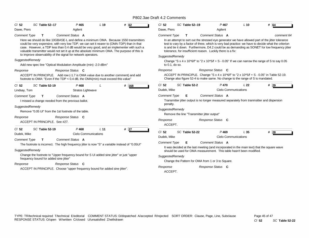
P802.3ae Draft 4.2 Comments
# 62Cl 52 SC Table 52–17 P 465 L 19
Comment Type THere we should do like 10GBASE-L and define a minimum OMA. Because 1550 transmitters could be very expensive, with very low TDP, we can set it nearer to (OMA-TDP) than in that case. However, a TDP less than 0.4 dB would be very good, and an implementer with such a valuable transmitter would not set it up at the absolute minimum OMA.�The purpose of this is to improve observability of the signal for network operators.
SuggestedRemedyAdd new spec line "Optical Modulation Amplitude (min) -2.0 dBm"
ResponseACCEPT IN PRINCIPLE. Add row (-1.7 is OMA value due to another comment) and add footnote to OMA: "Even if the TDP < 0.4 dB, the OMA(min) must exceed this value"
Comment Status A
Response Status C
Dawe, Piers Agilent
# 168Cl 52 SC Table 52-19 P 468 L
Comment Type TI missed a change needed from the previous ballot.
SuggestedRemedyRemove "0.05 UI" from the 1st footnote of the table.
ResponseACCEPT IN PRINCIPLE. See #27.
Comment Status A
Response Status C
Lindsay, Tom Stratos Lightwave
# 27Cl 52 SC Table 52-19 P 468 L 11
Comment Type TThe footnote is incorrect. The high frequency jitter is now "S" a variable instead of "0.05UI"
SuggestedRemedyChange the footnote to "Upper frequency bound for S UI added sine jitter" or just "upper frequency bound for added sine jitter"
ResponseACCEPT IN PRINCIPLE. Choose "upper frequency bound for added sine jitter".
Comment Status A
Response Status C
Dudek, Mike Cielo Communications
# 64Cl 52 SC Table 52–19 P 467 L 10
Comment Type TIn an attempt to sort out the stressed eye generator we have allowed part of the jitter tolerance test to vary by a factor of three, which is very bad practice: we have to decide what the criterion is and tie it down. Furthermore, D4.2 could be as demanding as SONET for low frequency jitter tolerance, for insufficient reason. Luckily there is a fix:
SuggestedRemedyChange "S x 4 x 10^6/f" to "2 x 10^5/f + S - 0.05"�If we can narrow the range of S to say 0.05 to 0.1, do so.
ResponseACCEPT IN PRINCIPLE. Change "S x 4 x 10^6/f" to "2 x 10^5/f + S - 0.05" in Table 52-19. Change also figure 52-4 to make same. No change to the range of S is mandated.
Comment Status A
Response Status C
comment 64
Dawe, Piers Agilent
# 29Cl 52 SC Table 52-2 P 470 L 22
Comment Type ETransmitter jitter output is no longer measured separately from tranmsitter and dispersion penalty.
SuggestedRemedyRemove the line "Transmitter jitter output"
ResponseACCEPT.
Comment Status A
Response Status C
Dudek, Mike Cielo Communications
# 28Cl 52 SC Table 52-22 P 469 L 35
Comment Type EIt was decided at the last meeting (and incorporated in the main text) that the square wave should be used for OMA measurement. This table hasn't been modified.
SuggestedRemedyChange the Pattern for OMA from 1 or 3 to Square.
ResponseACCEPT.
Comment Status A
Response Status C
Dudek, Mike Cielo Communications
TYPE: TR/technical required T/technical E/editorial COMMENT STATUS: D/dispatched A/accepted R/rejected SORT ORDER: Clause, Page, Line, SubclauseRESPONSE STATUS: O/open W/written C/closed U/unsatisfied Z/withdrawn Cl 52 SC Table 52-22
Page 45 of 47
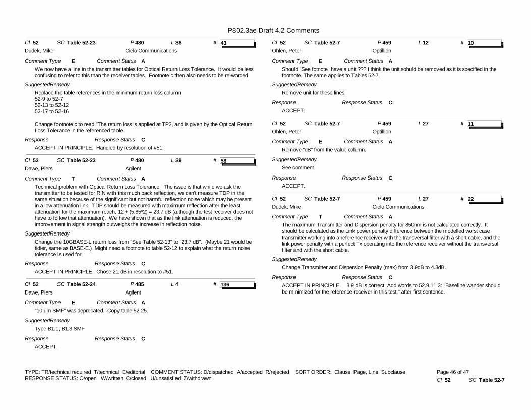
P802.3ae Draft 4.2 Comments
# 43Cl 52 SC Table 52-23 P 480 L 38
Comment Type EWe now have a line in the transmitter tables for Optical Return Loss Tolerance. It would be less confusing to refer to this than the receiver tables. Footnote c then also needs to be re-worded
SuggestedRemedyReplace the table references in the minimum return loss column52-9 to 52-752-13 to 52-1252-17 to 52-16
Change footnote c to read "The return loss is applied at TP2, and is given by the Optical Return Loss Tolerance in the referenced table.
ResponseACCEPT IN PRINCIPLE. Handled by resolution of #51.
Comment Status A
Response Status C
Dudek, Mike Cielo Communications
# 58Cl 52 SC Table 52-23 P 480 L 39
Comment Type TTechnical problem with Optical Return Loss Tolerance. The issue is that while we ask the transmitter to be tested for RIN with this much back reflection, we can't measure TDP in the same situation because of the significant but not harmful reflection noise which may be present in a low attenuation link. TDP should be measured with maximum reflection after the least attenuation for the maximum reach, 12 + (5.85*2) = 23.7 dB (although the test receiver does not have to follow that attenuation). We have shown that as the link attenuation is reduced, the improvement in signal strength outweighs the increase in reflection noise.
SuggestedRemedyChange the 10GBASE-L return loss from "See Table 52-13" to "23.7 dB". (Maybe 21 would be tidier, same as BASE-E.) Might need a footnote to table 52-12 to explain what the return noise tolerance is used for.
ResponseACCEPT IN PRINCIPLE. Chose 21 dB in resolution to #51.
Comment Status A
Response Status C
Dawe, Piers Agilent
# 136Cl 52 SC Table 52-24 P 485 L 4
Comment Type E"10 um SMF" was deprecated. Copy table 52-25.
SuggestedRemedyType B1.1, B1.3 SMF
ResponseACCEPT.
Comment Status A
Response Status C
Dawe, Piers Agilent
# 10Cl 52 SC Table 52-7 P 459 L 12
Comment Type EShould "See fotnote" have a unit ??? I think the unit sohuld be removed as it is specified in the footnote. The same applies to Tables 52-7.
SuggestedRemedyRemove unit for these lines.
ResponseACCEPT.
Comment Status A
Response Status C
Ohlen, Peter Optillion
# 11Cl 52 SC Table 52-7 P 459 L 27
Comment Type ERemove "dB" from the value column.
SuggestedRemedySee comment.
ResponseACCEPT.
Comment Status A
Response Status C
Ohlen, Peter Optillion
# 22Cl 52 SC Table 52-7 P 459 L 27
Comment Type TThe maximum Transmitter and Dispersion penalty for 850nm is not calculated correctly. It should be calculated as the Link power penalty difference between the modelled worst case transmitter working into a reference receiver with the transversal filter with a short cable, and the link power penalty with a perfect Tx operating into the reference receiver without the transversal filter and with the short cable.
SuggestedRemedyChange Transmitter and Dispersion Penalty (max) from 3.9dB to 4.3dB.
ResponseACCEPT IN PRINCIPLE. 3.9 dB is correct. Add words to 52.9.11.3: "Baseline wander should be minimized for the reference receiver in this test." after first sentence.
Comment Status A
Response Status C
Dudek, Mike Cielo Communications
TYPE: TR/technical required T/technical E/editorial COMMENT STATUS: D/dispatched A/accepted R/rejected SORT ORDER: Clause, Page, Line, SubclauseRESPONSE STATUS: O/open W/written C/closed U/unsatisfied Z/withdrawn Cl 52 SC Table 52-7
Page 46 of 47

P802.3ae Draft 4.2 Comments
# 70Cl 52 SC Table 52–7 P 459 L 15
Comment Type THere we may need to add at least a statement of minimum Average launch power to make this standard more acceptable to operators. We can take advice on how important this is for 10GBASE-S. At the last meeting I misunderstood my own diagrams but having cleaned that up:�
SuggestedRemedyOption 1 (technical): add new spec line "Average launch power (min) x dBm" Add footnote "Average power is not the principal criterion of signal strength. A transmitted signal with average powers between x and y dBm may or may not be compliant. The user may inspect the signal's OMA and inner eye opening." where x is 0.5 to 1 dB above the theoretical minimum derived from the normative specs, and y is the theoretical maximum.�Option 2 (editorial): Add footnote "Average power is not the principal criterion of signal strength. A transmitted signal below xxx dBm cannot be compliant." where xxx is the theoretical minimum derived from the normative specs.�
ResponseACCEPT IN PRINCIPLE. See #77.
Comment Status A
Response Status C
Dawe, Piers Agilent
# 59Cl 52 SC Table 52–7,12,16 P 459465 L
Comment Type EProblem with "Optical Return Loss Tolerance (max)". These numbers may be the least positive that the transmitter need withstand but are the most positive that would be applied in a test. We can't decide if it should be max or min, readers will have the same problem. But the word "Tolerance" makes clear what we mean.
SuggestedRemedyDelete "(max)" (three times).
ResponseWithdrawn.
Comment Status D
Response Status Z
Dawe, Piers Agilent
# 57Cl 52 SC Table 52–9,13,17 P 4636 L
Comment Type EProblem with "Vertical eye closure penalty (max)" and "Stressed eye jitter (max)". These numbers may be the most the receiver need withstand but are the least applied in the stress test. max or min? No need to go there, the footnote is clear.
SuggestedRemedyDelete "(max)" (six times).
ResponseACCEPT IN PRINCIPLE. See #179.
Comment Status A
Response Status C
Dawe, Piers Agilent
# 166Cl 53 SC 53.9.14 P 520 L 14
Comment Type EWhy are Figure 53-12 and Figure 52-11 so different when they seem to be showing the same thing?
SuggestedRemedyMake the two figures the same unless there is a reason for a difference.
Response
Comment Status D
Response Status Z
Thaler, Pat Agilent
TYPE: TR/technical required T/technical E/editorial COMMENT STATUS: D/dispatched A/accepted R/rejected SORT ORDER: Clause, Page, Line, SubclauseRESPONSE STATUS: O/open W/written C/closed U/unsatisfied Z/withdrawn Cl 53 SC 53.9.14
Page 47 of 47