Embed Size (px)
Citation preview
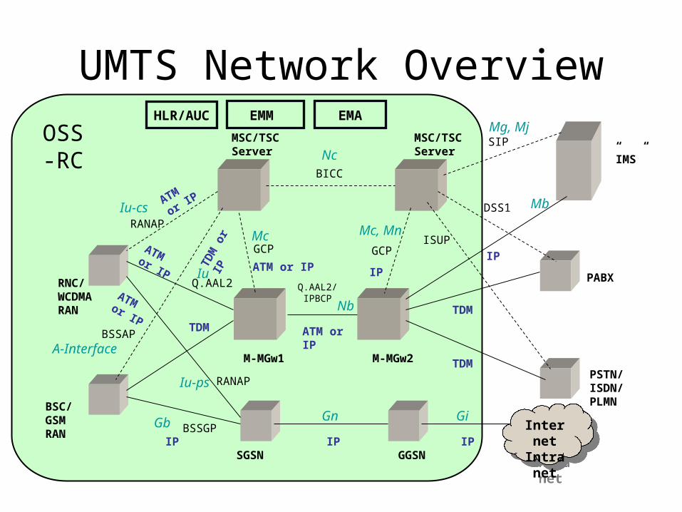
UMTS Network Overview
RNC/WCDMARAN
PABX
BSC/ GSM RAN
PSTN/ISDN/PLMN
M-MGw1 M-MGw2
MSC/TSCServer
MSC/TSCServer
BICC
GCP GCP
Q.AAL2/ IPBCP
TDM
TDM
ATM or IP ATM or IP IP
ATM or IP
RANAP
BSSAP
Q.AAL2
ISUP
DSS1
A-Interface
Mc
Nb
Iu-cs
Nc
IuIP
TDM
SIPMg, Mj
Mc, Mn
Mb
SGSN GGSNIP
RANAP
Gb Interne
tIntrane
t
Internet
Intranet
ATM or IP
Iu-ps
”IMS”
OSS-RC
IP
HLR/AUC EMM EMA
Gn Gi BSSGP
IP
ATM
or IPTD
M o
r IP
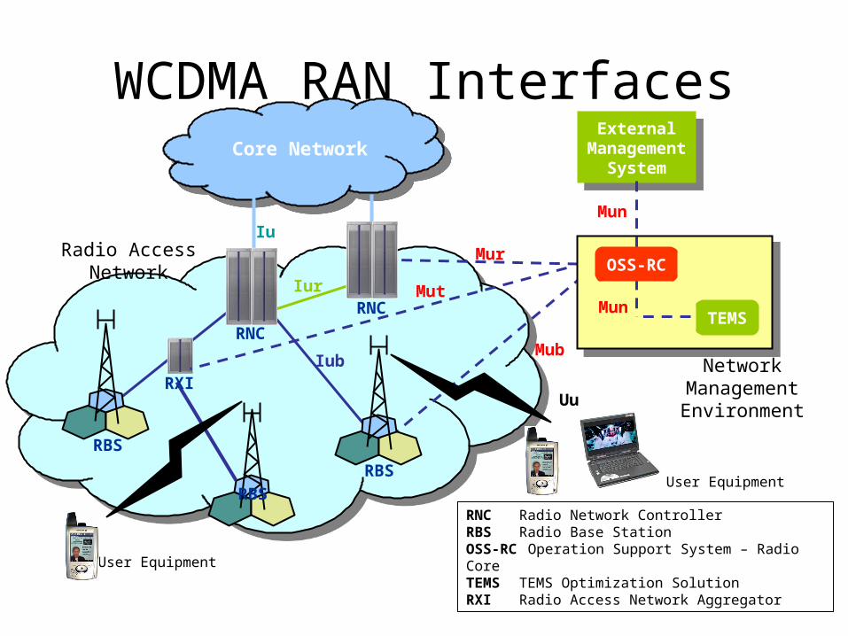
WCDMA RAN Interfaces
Radio AccessNetwork
Iub
Iu
Iur
Mub
Mur
RNC Radio Network ControllerRBS Radio Base StationOSS-RC Operation Support System – Radio CoreTEMS TEMS Optimization Solution RXI Radio Access Network Aggregator
User Equipment
Uu
ExternalManagement
System
ExternalManagement
System
Mun
Mun
NetworkManagementEnvironment
OSS-RC
TEMS
Core Network
RNC
RXI
RNC
RBS
RBS
RBSUser Equipment
Mut
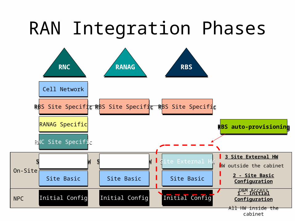
RAN Integration Phases
On-SiteOn-Site
NPCNPC
RNCRNC RBSRBS
Cell NetworkCell Network
Initial ConfigInitial Config
RANAG SpecificRANAG Specific
RNC Site SpecificRNC Site Specific
Site External HWSite External HW
Site BasicSite Basic
RBS Site SpecificRBS Site Specific
Initial ConfigInitial Config
Site External HWSite External HW
Site BasicSite Basic
Initial ConfigInitial Config
Site External HWSite External HW
Site BasicSite Basic
RBS Site SpecificRBS Site Specific
RANAGRANAG
RBS Site SpecificRBS Site Specific
1 - Initial Configuration
All HW inside the cabinet
2 - Site Basic Configuration
O&M Access
3 Site External HW
HW outside the cabinet
RBS auto-provisioningRBS auto-provisioning
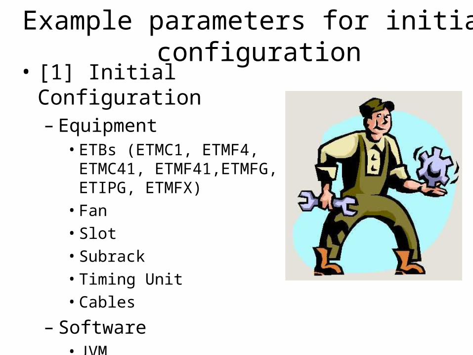
Example parameters for initial configuration
• [1] Initial Configuration– Equipment
• ETBs (ETMC1, ETMF4, ETMC41, ETMF41,ETMFG, ETIPG, ETMFX)
• Fan• Slot• Subrack• Timing Unit• Cables
– Software• JVM• Load Modules• Programs• Reliable Program Uniters
(RPU)
Example of parameters for Site Basic Configuration
• [2] Site Basic Configuration– IP data
• IP Address• Subnet Mask• DNS Server Address• Default Router
– TN Equipment for Mur, Mut and Mub
• ATM Port• Ethernet Port• IP Links• Routing options
Example of parameter for Site External Hardware configuration
• [3] Site External Hardware Configuration
– Antenna Feeder Cable
• Branch A&B/sector
– Antenna Jumper Cable
• Branch A&B/sector
– Antenna System Controller ASC
– Assisted Global Positioning System A-GPS
– SAU External Alarm Unit (RBS 6000)
RAN Configuration Phases
OMC
RNCRNC RBSRBS
Cell NetworkCell Network
RANAG SpecificRANAG Specific
RNC Site SpecificRNC Site Specific
Site External HWSite External HW
RBS Site SpecificRBS Site Specific
Site External HWSite External HW
RBS Site SpecificRBS Site Specific
7 - Cell Network
Cell, Channels and Relations
RANAGRANAG
RBS Site SpecificRBS Site Specific6 - Site Specific RBS
TN Data and RN Protocols Iub
5 - Site Specific RANAG
Intermediate Node Preparation
4 - Site Specific RNC
TN Data and RN Protocols Iu/Iur
Initial ConfigInitial Config
Site BasicSite Basic
Initial ConfigInitial Config
Site BasicSite Basic
Initial ConfigInitial Config
Site External HWSite External HW
Site BasicSite Basic
Example of parameters for RNC Site Specific Configuration
• [4] RNC Site Specific Configuration
– Impacts RNC only
– Iu Interface
• Iu CS and Iu PS
• Transport Network (IP or ATM)
• SS7
• SIGTRAN (SS7 over IP)
• RANAP
• User Plane
– Iur Interface
• Transport Network
• SS7 / SIGTRAN
• RNSAP
• User Plane
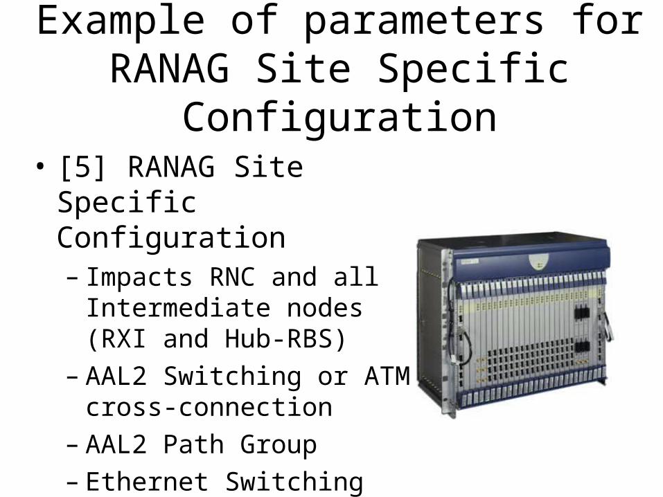
Example of parameters for RANAG Site Specific
Configuration• [5] RANAG Site Specific
Configuration– Impacts RNC and all
Intermediate nodes (RXI and Hub-RBS)
– AAL2 Switching or ATM cross-connection
– AAL2 Path Group– Ethernet Switching
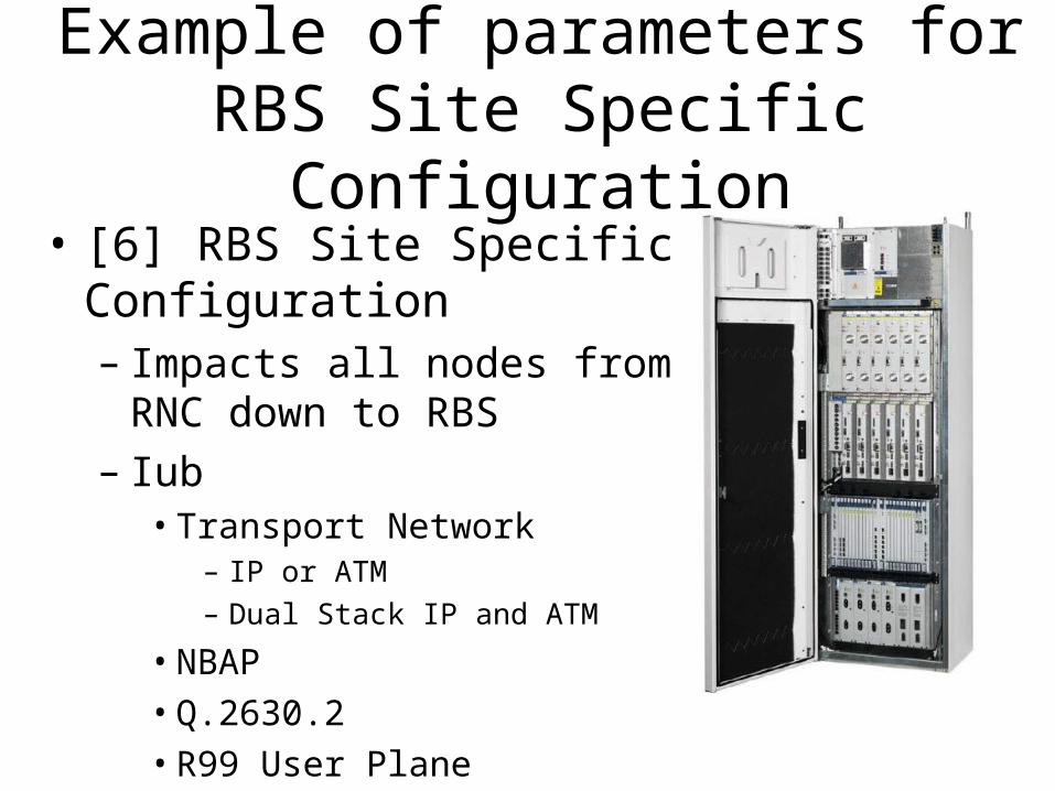
Example of parameters for RBS Site Specific Configuration
• [6] RBS Site Specific Configuration– Impacts all nodes from RNC
down to RBS– Iub
• Transport Network– IP or ATM– Dual Stack IP and ATM
• NBAP• Q.2630.2• R99 User Plane• HSPA User Plane
– Common parameters for most of the RBSs
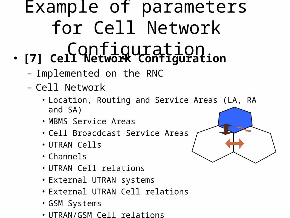
Example of parameters for Cell Network Configuration
• [7] Cell Network Configuration– Implemented on the RNC– Cell Network
• Location, Routing and Service Areas (LA, RA and SA)• MBMS Service Areas• Cell Broacdcast Service Areas• UTRAN Cells• Channels• UTRAN Cell relations• External UTRAN systems• External UTRAN Cell relations• GSM Systems• UTRAN/GSM Cell relations• HSPA• Frame Synchronization parameters
• BCR available for Cell Network Configuration
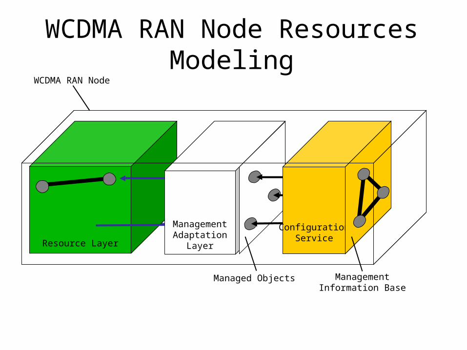
Resource Layer
WCDMA RAN Node Resources Modeling
ManagementAdaptation
Layer
Managed Objects
ConfigurationService
WCDMA RAN Node
Management Information Base
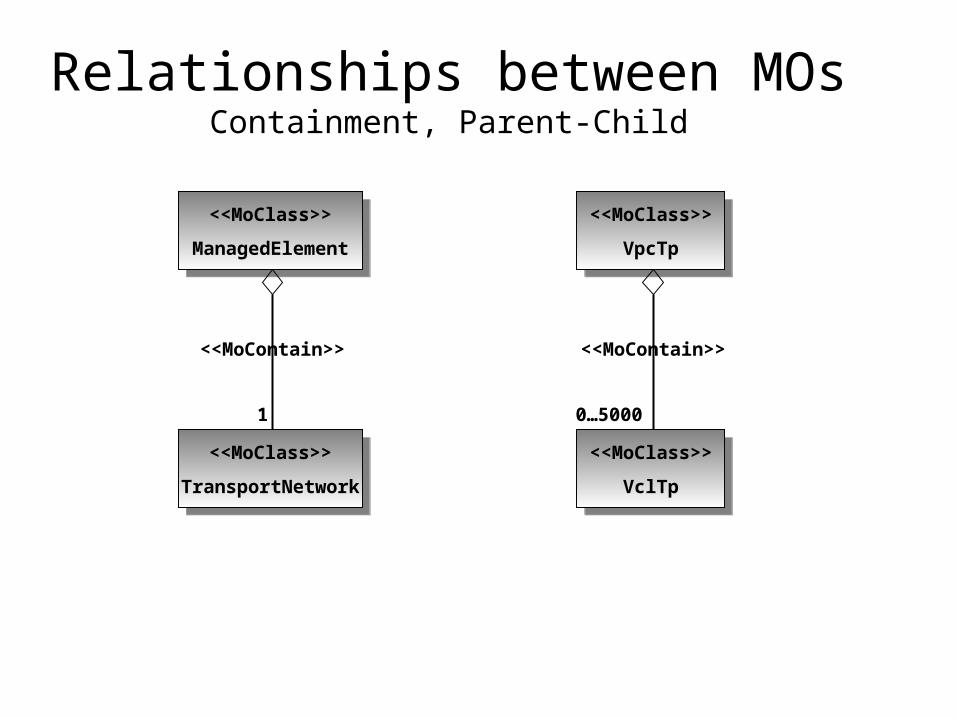
Relationships between MOsContainment, Parent-Child
<<MoClass>>
VpcTp
<<MoClass>>
VpcTp
<<MoClass>>
VclTp
<<MoClass>>
VclTp
<<MoContain>>
0…5000
<<MoClass>>
ManagedElement
<<MoClass>>
ManagedElement
<<MoClass>>
TransportNetwork
<<MoClass>>
TransportNetwork
<<MoContain>>
1
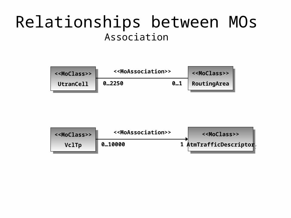
Relationships between MOsAssociation
<<MoClass>>
RoutingArea
<<MoClass>>
RoutingArea<<MoClass>>
UtranCell
<<MoClass>>
UtranCell
<<MoAssociation>>
0…2250 0…1
<<MoClass>>
AtmTrafficDescriptor
<<MoClass>>
AtmTrafficDescriptor<<MoClass>>
VclTp
<<MoClass>>
VclTp
<<MoAssociation>>
0…10000 1
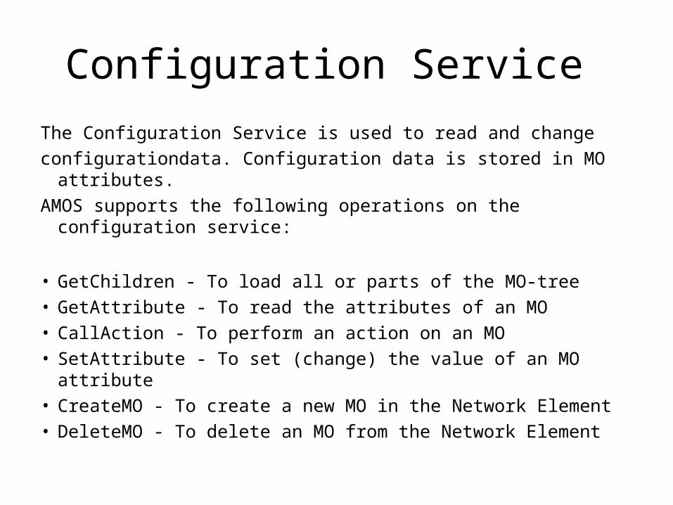
Configuration Service
The Configuration Service is used to read and change
configurationdata. Configuration data is stored in MO attributes.
AMOS supports the following operations on the configuration service:
• GetChildren - To load all or parts of the MO-tree • GetAttribute - To read the attributes of an MO • CallAction - To perform an action on an MO • SetAttribute - To set (change) the value of an MO attribute • CreateMO - To create a new MO in the Network Element • DeleteMO - To delete an MO from the Network Element
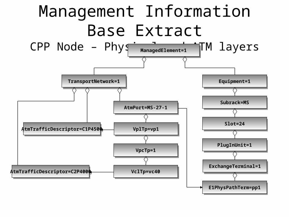
Management Information Base Extract
CPP Node – Physical and ATM layersManagedElement=1ManagedElement=1
TransportNetwork=1TransportNetwork=1
AtmTrafficDescriptor=C1P4500AtmTrafficDescriptor=C1P4500
Equipment=1Equipment=1
Subrack=MSSubrack=MS
Slot=24Slot=24
PlugInUnit=1PlugInUnit=1
ExchangeTerminal=1ExchangeTerminal=1
E1PhysPathTerm=pp1E1PhysPathTerm=pp1
AtmTrafficDescriptor=C2P4000AtmTrafficDescriptor=C2P4000
AtmPort=MS-27-1AtmPort=MS-27-1
VplTp=vp1VplTp=vp1
VpcTp=1VpcTp=1
VclTp=vc40VclTp=vc40
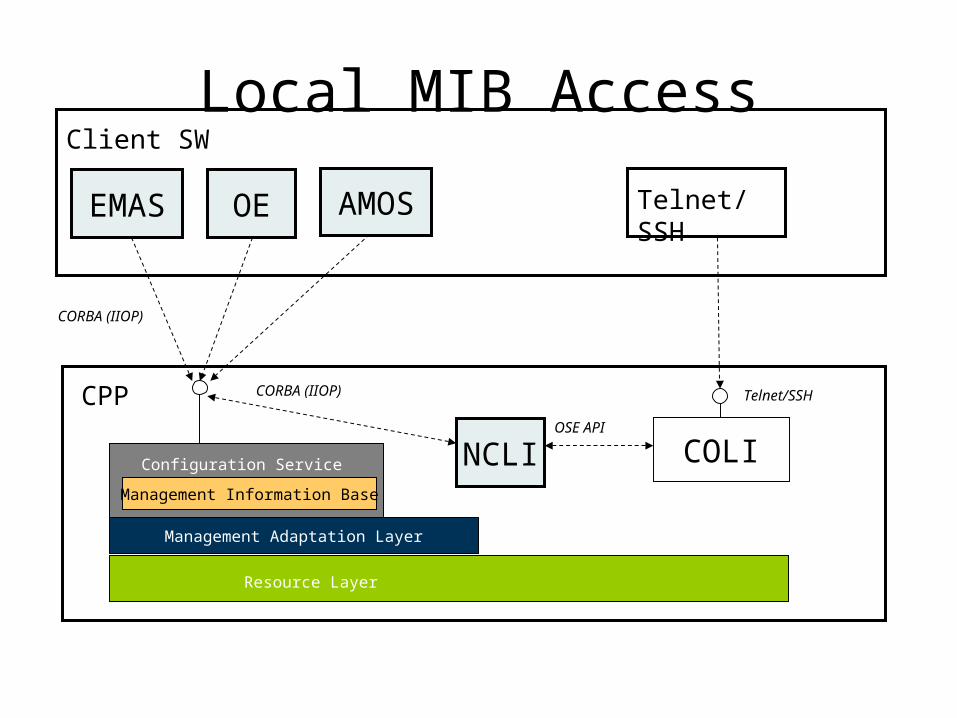
Local MIB Access
Resource Layer
Management Adaptation Layer
CPP
COLIConfiguration Service
EMAS
Client SW
OE
NCLIOSE API
Telnet/SSH
CORBA (IIOP) Telnet/SSH
CORBA (IIOP)
Management Information Base
AMOS
MSC-S
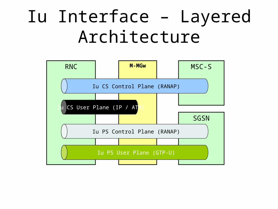
Iu Interface – Layered Architecture
RNC M-MGw
Iu CS Control Plane (RANAP)
SGSN
Iu CS User Plane (IP / ATM)
Iu PS Control Plane (RANAP)
Iu PS User Plane (GTP-U)
RNC
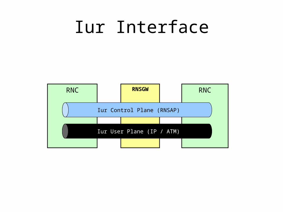
Iur Interface
RNC RNSGW
Iur Control Plane (RNSAP)
Iur User Plane (IP / ATM)
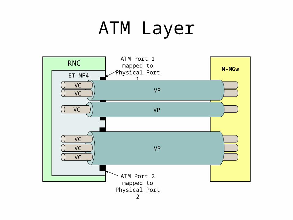
ATM Layer
RNC
ET-MF4M-MGw
ATM Port 1 mapped to
Physical Port 1
ATM Port 2 mapped to
Physical Port 2
VPVC
VC
VPVC
VP
VC
VC
VC
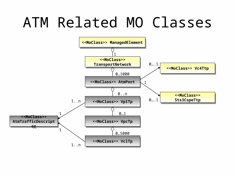
ATM Related MO Classes<<MoClass>> ManagedElement<<MoClass>> ManagedElement
<<MoClass>> AtmPort<<MoClass>> AtmPort
<<MoClass>> Vc4Ttp<<MoClass>> Vc4Ttp0….1
<<MoClass>> TransportNetwork
<<MoClass>> TransportNetwork
1
0…1000
<<MoClass>> Sts3CspeTtp
<<MoClass>> Sts3CspeTtp0….1
<<MoClass>> VplTp<<MoClass>> VplTp
0..n
<<MoClass>> VpcTp<<MoClass>> VpcTp
0…1
<<MoClass>> VclTp<<MoClass>> VclTp
0…5000
<<MoClass>> AtmTrafficDescriptor
<<MoClass>> AtmTrafficDescriptor
1
1
1..n
1..n
1
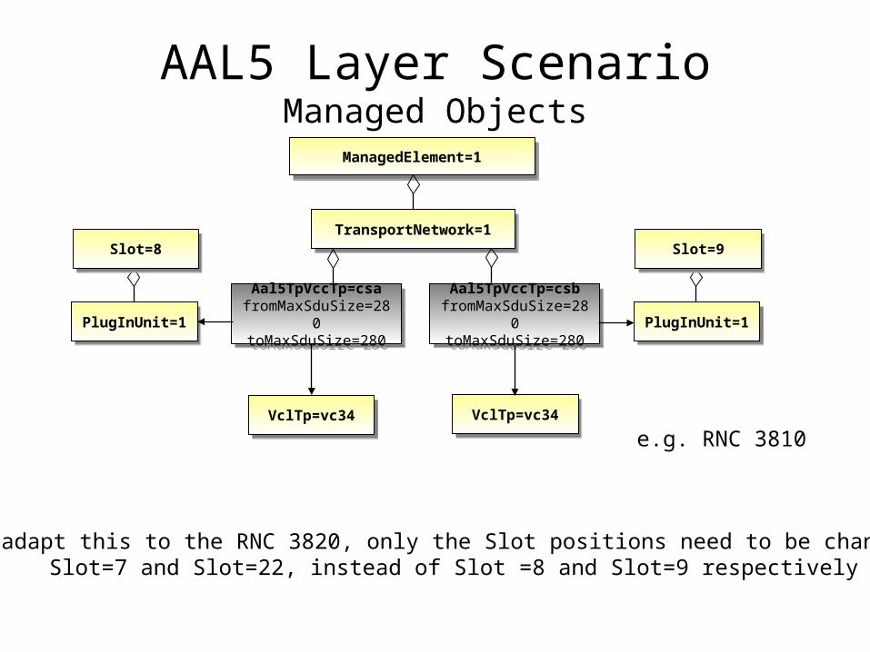
AAL5 Layer ScenarioManaged Objects
ManagedElement=1ManagedElement=1
Aal5TpVccTp=csa fromMaxSduSize=280
toMaxSduSize=280
Aal5TpVccTp=csa fromMaxSduSize=280
toMaxSduSize=280
TransportNetwork=1TransportNetwork=1
VclTp=vc34VclTp=vc34
PlugInUnit=1PlugInUnit=1
Slot=8Slot=8
Aal5TpVccTp=csb fromMaxSduSize=280
toMaxSduSize=280
Aal5TpVccTp=csb fromMaxSduSize=280
toMaxSduSize=280 PlugInUnit=1PlugInUnit=1
Slot=9Slot=9
VclTp=vc34VclTp=vc34
e.g. RNC 3810
To adapt this to the RNC 3820, only the Slot positions need to be changed:Slot=7 and Slot=22, instead of Slot =8 and Slot=9 respectively
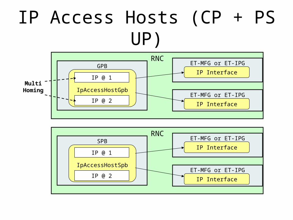
IP Access Hosts (CP + PS UP)
RNCET-MFG or ET-IPG
IP Interface
ET-MFG or ET-IPG
GPB
IP Interface
IpAccessHostGpb
IP @ 1
IP @ 2
Multi Homing
RNCET-MFG or ET-IPG
IP Interface
ET-MFG or ET-IPG
SPB
IP Interface
IpAccessHostSpb
IP @ 1
IP @ 2
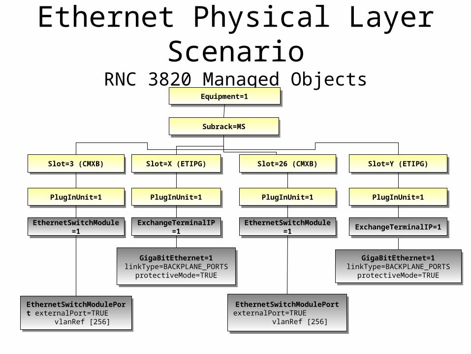
Ethernet Physical Layer Scenario
RNC 3820 Managed Objects
Slot=3 (CMXB)Slot=3 (CMXB)
Equipment=1Equipment=1
Subrack=MSSubrack=MS
PlugInUnit=1PlugInUnit=1
EthernetSwitchModule=1EthernetSwitchModule=1
EthernetSwitchModulePort externalPort=TRUE
vlanRef [256]
EthernetSwitchModulePort externalPort=TRUE
vlanRef [256]
Slot=X (ETIPG)Slot=X (ETIPG)
PlugInUnit=1PlugInUnit=1
ExchangeTerminalIP=1ExchangeTerminalIP=1
Slot=Y (ETIPG)Slot=Y (ETIPG)
PlugInUnit=1PlugInUnit=1
Slot=26 (CMXB)Slot=26 (CMXB)
PlugInUnit=1PlugInUnit=1
EthernetSwitchModule=1EthernetSwitchModule=1
GigaBitEthernet=1 linkType=BACKPLANE_PORTS
protectiveMode=TRUE
GigaBitEthernet=1 linkType=BACKPLANE_PORTS
protectiveMode=TRUE
EthernetSwitchModulePort externalPort=TRUE
vlanRef [256]
EthernetSwitchModulePort externalPort=TRUE
vlanRef [256]
ExchangeTerminalIP=1ExchangeTerminalIP=1
GigaBitEthernet=1 linkType=BACKPLANE_PORTS
protectiveMode=TRUE
GigaBitEthernet=1 linkType=BACKPLANE_PORTS
protectiveMode=TRUE
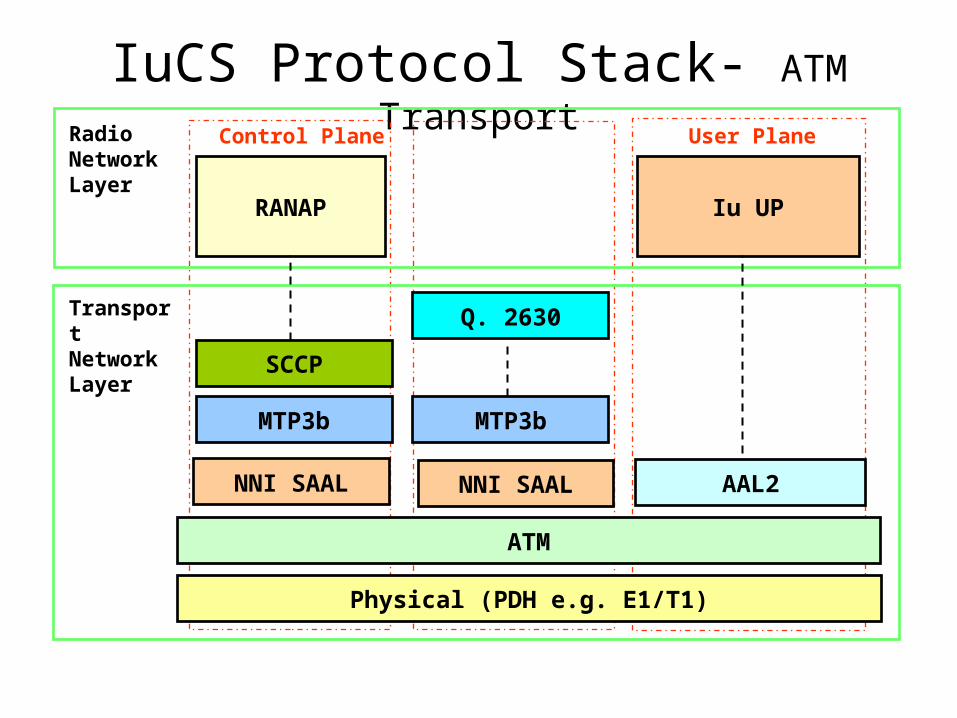
IuCS Protocol Stack- ATM Transport
Physical (PDH e.g. E1/T1)
RANAP
RadioNetworkLayer
Control Plane User Plane
ATM
NNI SAALNNI SAAL
TransportNetworkLayer
Iu UP
AAL2
SCCP
MTP3b MTP3b
Q. 2630
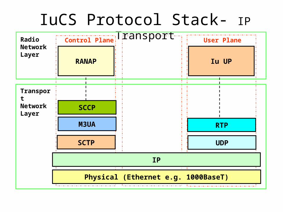
IuCS Protocol Stack- IP Transport
Physical (Ethernet e.g. 1000BaseT)
RANAP
RadioNetworkLayer
Control Plane User Plane
IP
SCTP
TransportNetworkLayer
Iu UP
UDP
SCCP
M3UA RTP

MTP3 Protocol, General Principle:
Understanding MTP3 (II)
2-321 325
578 567
456
What is my SPCI?My addres is 2-321 (2 is theNetworkID and 321 is the SPC).This is configured in theMTP3 Signaling Point
234
Signaling Link 1
Signaling Link 2
Signaling Link 1
Signaling Link 2
Signaling Link 3
To reach( Signalling Route Set )
Use
SLSASR1SRS to 578
SLSASR1
SRS to 567
SLSBSR1SRS to 456
SLSBSR1SRS to 325
M3UA ASR2
M3UA ASR1SRS to 234
What are the destinations?What is the Path toreach the destination?
M3UA Association A
Signaling
Link Set A
Signaling
Link Set B
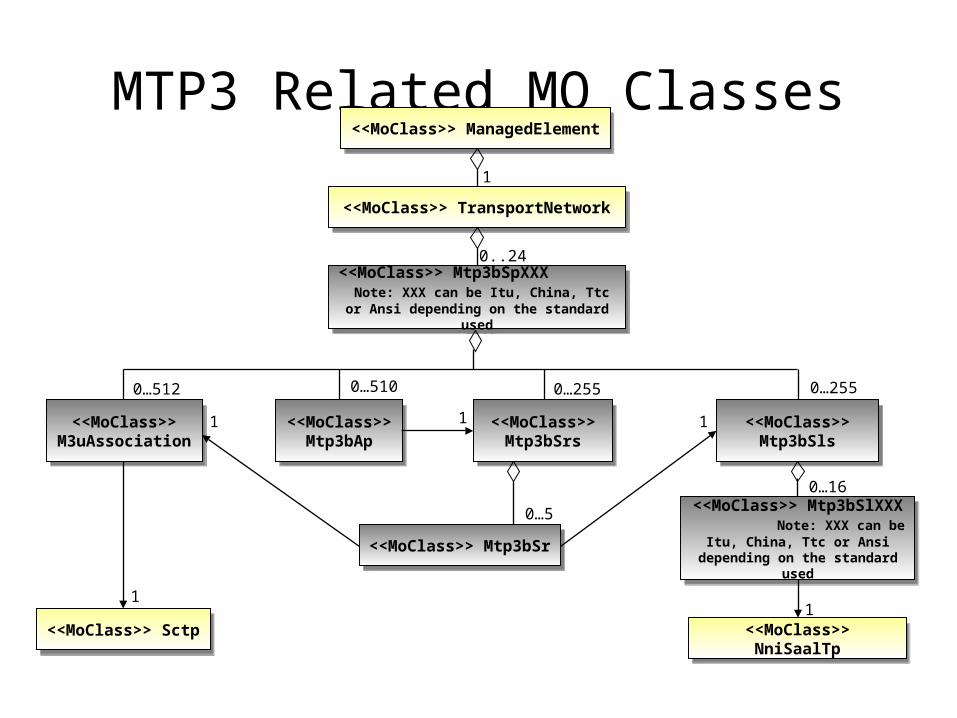
MTP3 Related MO Classes<<MoClass>> ManagedElement<<MoClass>> ManagedElement
<<MoClass>> TransportNetwork<<MoClass>> TransportNetwork
1
<<MoClass>> Mtp3bSpXXX Note: XXX can be Itu, China, Ttc or Ansi
depending on the standard used
<<MoClass>> Mtp3bSpXXX Note: XXX can be Itu, China, Ttc or Ansi
depending on the standard used
0..24
<<MoClass>> Mtp3bAp
<<MoClass>> Mtp3bAp
<<MoClass>> Mtp3bSrs
<<MoClass>> Mtp3bSrs
<<MoClass>> Mtp3bSls
<<MoClass>> Mtp3bSls
<<MoClass>> M3uAssociation
<<MoClass>> M3uAssociation
<<MoClass>> Sctp<<MoClass>> Sctp<<MoClass>> NniSaalTp<<MoClass>> NniSaalTp
<<MoClass>> Mtp3bSr<<MoClass>> Mtp3bSr
<<MoClass>> Mtp3bSlXXX Note: XXX can be Itu, China,
Ttc or Ansi depending on the standard used
<<MoClass>> Mtp3bSlXXX Note: XXX can be Itu, China,
Ttc or Ansi depending on the standard used
0…255 0…2550…512 0…510
1
0…16
0…5
1
1 11
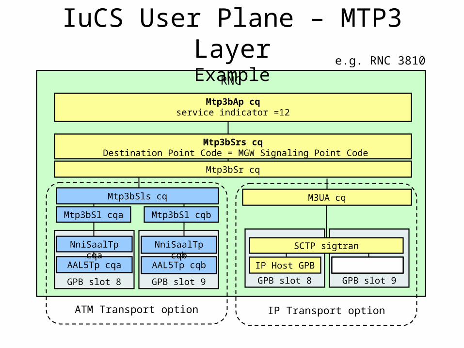
RNC
IuCS User Plane – MTP3 LayerExample
GPB slot 9
AAL5Tp cqb
GPB slot 8
AAL5Tp cqa
NniSaalTp cqa
Mtp3bSl cqa
Mtp3bSls cq
Mtp3bSr cq
Mtp3bSrs cq Destination Point Code = MGW Signaling Point Code
Mtp3bAp cqservice indicator =12
M3UA cq
NniSaalTp cqb
Mtp3bSl cqb
GPB slot 9GPB slot 8
SCTP sigtran
IP Host GPB
ATM Transport option IP Transport option
IP Host GPB
e.g. RNC 3810
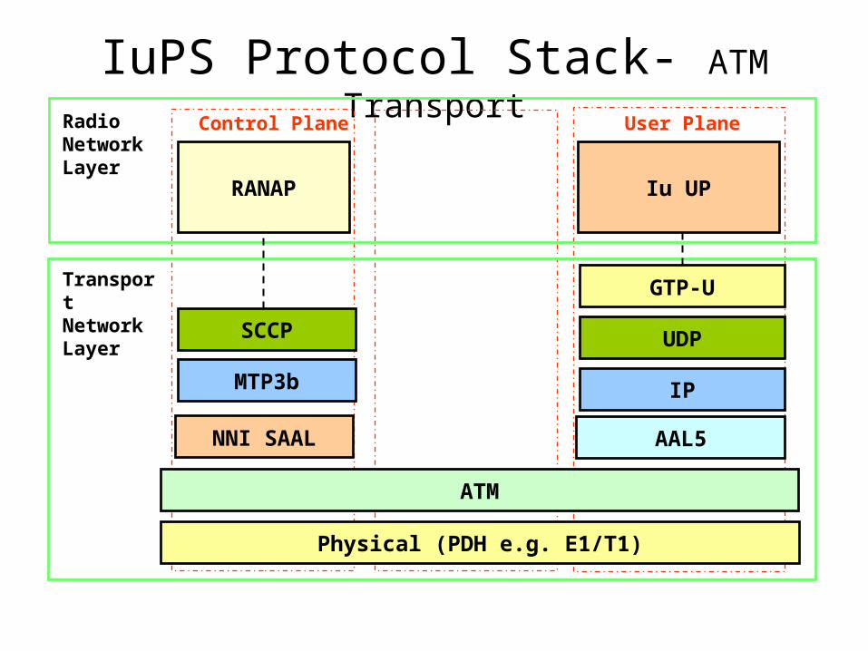
IuPS Protocol Stack- ATM Transport
Physical (PDH e.g. E1/T1)
RANAP
RadioNetworkLayer
Control Plane User Plane
ATM
NNI SAAL
TransportNetworkLayer
Iu UP
AAL5
SCCP
MTP3b IP
UDP
GTP-U

IuPS Protocol Stack- IP Transport
Physical (Ethernet e.g. 1000BaseT)
RANAP
RadioNetworkLayer
Control Plane User Plane
IP
SCTP
TransportNetworkLayer
Iu UP
UDP
SCCP
M3UA GTP-U
RNC
ATM Transport option
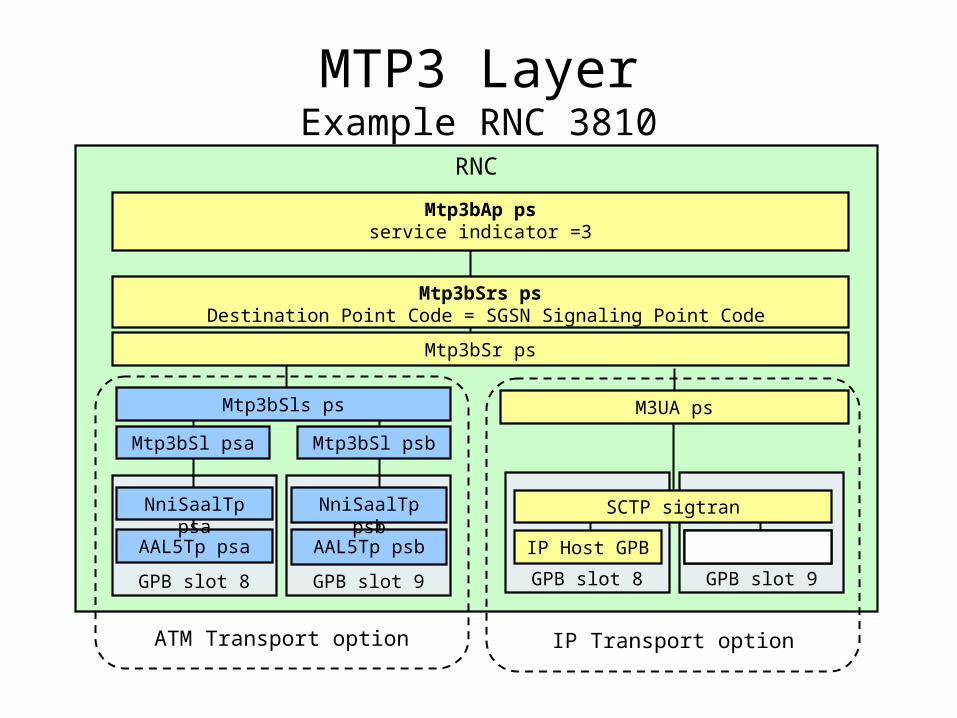
MTP3 LayerExample RNC 3810
GPB slot 9
AAL5Tp psb
GPB slot 8
AAL5Tp psa
NniSaalTp psa
Mtp3bSl psa
Mtp3bSls ps
Mtp3bSr ps
Mtp3bSrs ps Destination Point Code = SGSN Signaling Point Code
Mtp3bAp psservice indicator =3
M3UA ps
NniSaalTp psb
Mtp3bSl psb
GPB slot 9GPB slot 8
SCTP sigtran
IP Host GPB
IP Transport option
IP Host GPB
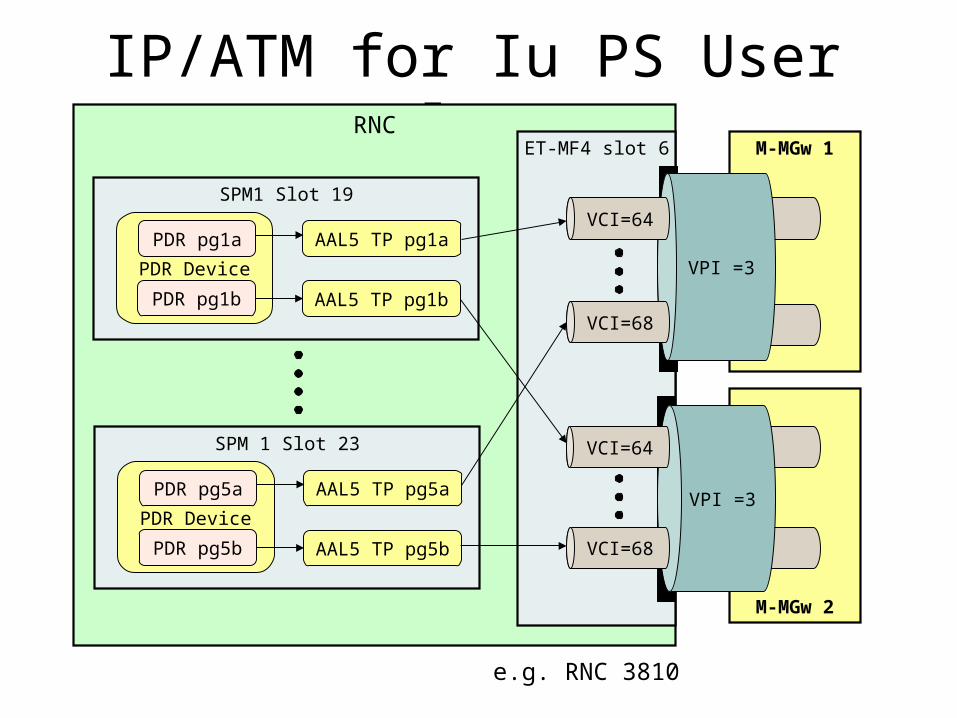
IP/ATM for Iu PS User PlaneRNC
SPM1 Slot 19
AAL5 TP pg1a
PDR Device
PDR pg1a
PDR pg1b
M-MGw 2
ET-MF4 slot 6 M-MGw 1
AAL5 TP pg1b
SPM 1 Slot 23
AAL5 TP pg5a
PDR Device
PDR pg5a
PDR pg5b AAL5 TP pg5b
VPI =3
VCI=68
VCI=64
VPI =3
VCI=64
VCI=68
e.g. RNC 3810
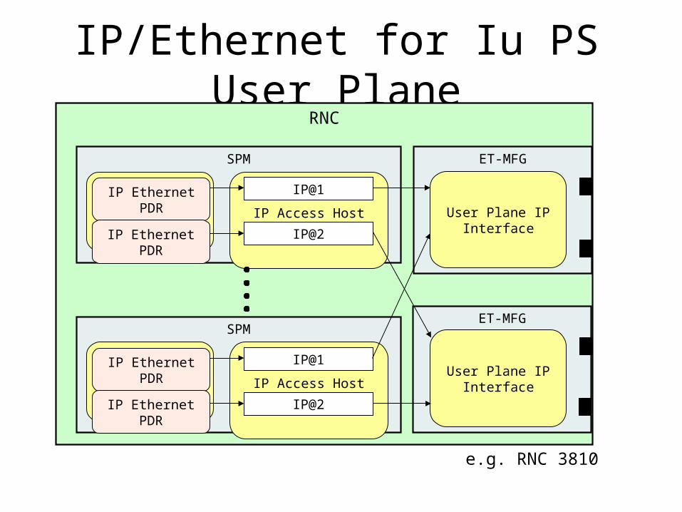
IP/Ethernet for Iu PS User Plane
RNC
ET-MFG
User Plane IP Interface
ET-MFG
SPM
User Plane IP Interface
IP Access Host SPB
IP@1
IP@2
PDR Device
IP Ethernet PDR
IP Ethernet PDR
SPM
IP Access Host SPB
IP@1
IP@2
PDR Device
IP Ethernet PDR
IP Ethernet PDR
e.g. RNC 3810
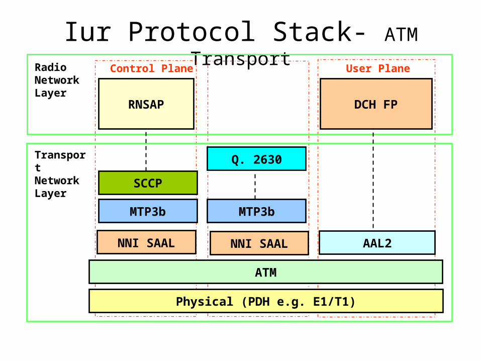
Iur Protocol Stack- ATM Transport
Physical (PDH e.g. E1/T1)
RNSAP
RadioNetworkLayer
Control Plane User Plane
ATM
NNI SAALNNI SAAL
Q. 2630TransportNetworkLayer
DCH FP
AAL2
SCCP
MTP3b MTP3b
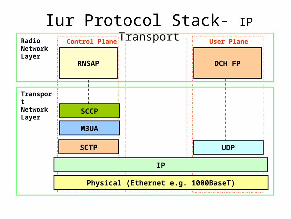
Iur Protocol Stack- IP Transport
Physical (Ethernet e.g. 1000BaseT)
RNSAP
RadioNetworkLayer
Control Plane User Plane
IP
SCTP
TransportNetworkLayer
DCH FP
UDP
SCCP
M3UA
RNC 2
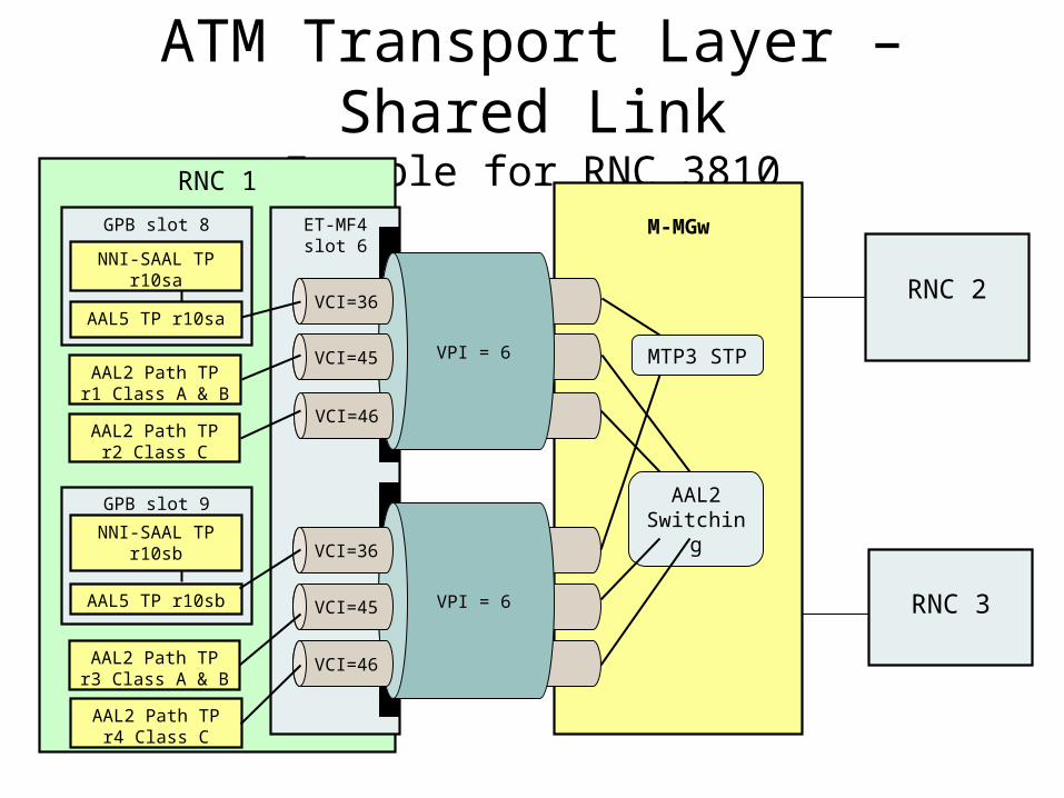
ATM Transport Layer – Shared Link
Example for RNC 3810RNC 1
ET-MF4slot 6
M-MGw
GPB slot 9
AAL5 TP r10sb
GPB slot 8
AAL5 TP r10sa
NNI-SAAL TP r10sb
NNI-SAAL TP r10sa
RNC 3
AAL2 Path TP r1 Class A & B
AAL2 Path TP r3 Class A & B
MTP3 STP
AAL2 Path TP r4 Class C
VPI = 6
VCI=36
VCI=45
VCI=46
VPI = 6
VCI=36
VCI=45
VCI=46AAL2 Path TP r2
Class C
AAL2 Switching
RNC 1
RPU=ans_aal2cpsrc_12_central
RPU=ans_aal2ap_13_sccp
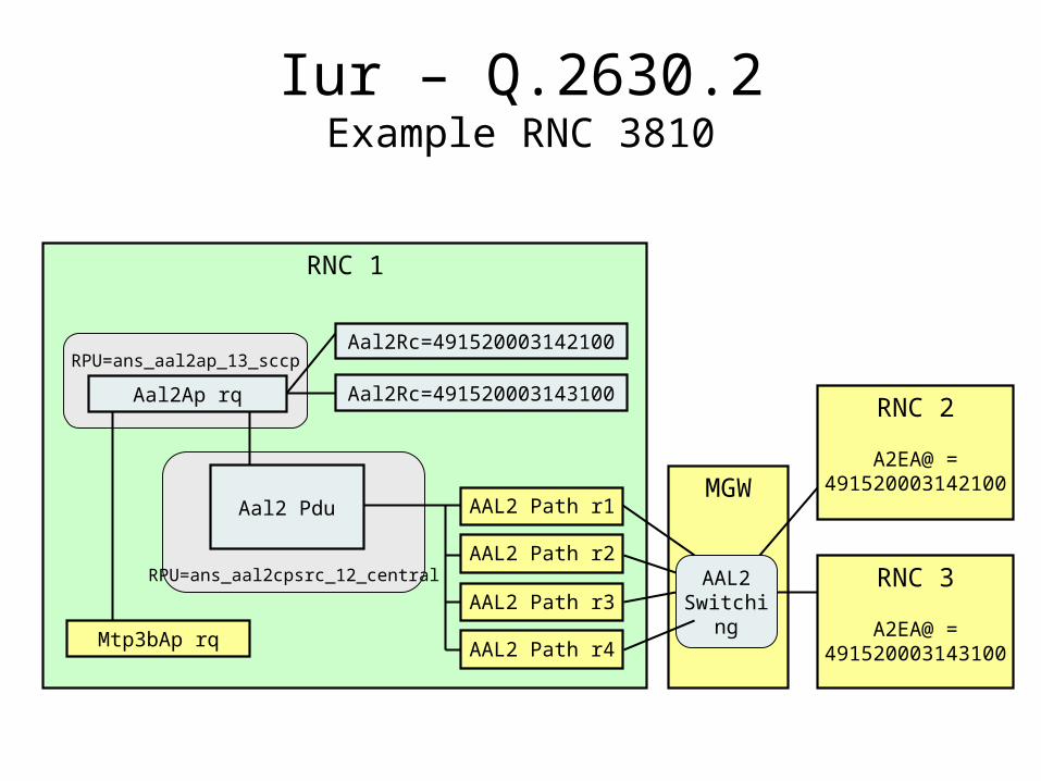
Iur – Q.2630.2Example RNC 3810
Aal2Ap rq
Aal2 Pdu
Aal2Rc=491520003142100
Mtp3bAp rq
RNC 3
A2EA@ = 491520003143100
Aal2Rc=491520003143100RNC 2
A2EA@ = 491520003142100
AAL2 Path r1
AAL2 Path r2
AAL2 Path r3
AAL2 Path r4
MGW
AAL2 Switching

RNC 1
RPU=ans_aal2cpsrc_12_central
RPU=ans_aal2ap_13_sccp
Iur – Q.2630.2Example RNC 3810
Aal2Ap rq
Aal2 Pdu
Aal2Rc=491520003142100
Mtp3bAp rq
RNC 3
A2EA@ = 491520003143100
Aal2Rc=491520003143100RNC 2
A2EA@ = 491520003142100
AAL2 Path r1
AAL2 Path r2
AAL2 Path r3
AAL2 Path r4
MGW
AAL2 Switching

RNC 1
RPU=ans_aal2cpsrc_12_central
RPU=ans_aal2ap_13_sccp
Iur – Q.2630.2Example RNC 3810
Aal2Ap rq
Aal2 Pdu
Aal2Rc=491520003142100
Mtp3bAp rq
RNC 3
A2EA@ = 491520003143100
Aal2Rc=491520003143100RNC 2
A2EA@ = 491520003142100
AAL2 Path r1
AAL2 Path r2
AAL2 Path r3
AAL2 Path r4
MGW
AAL2 Switching
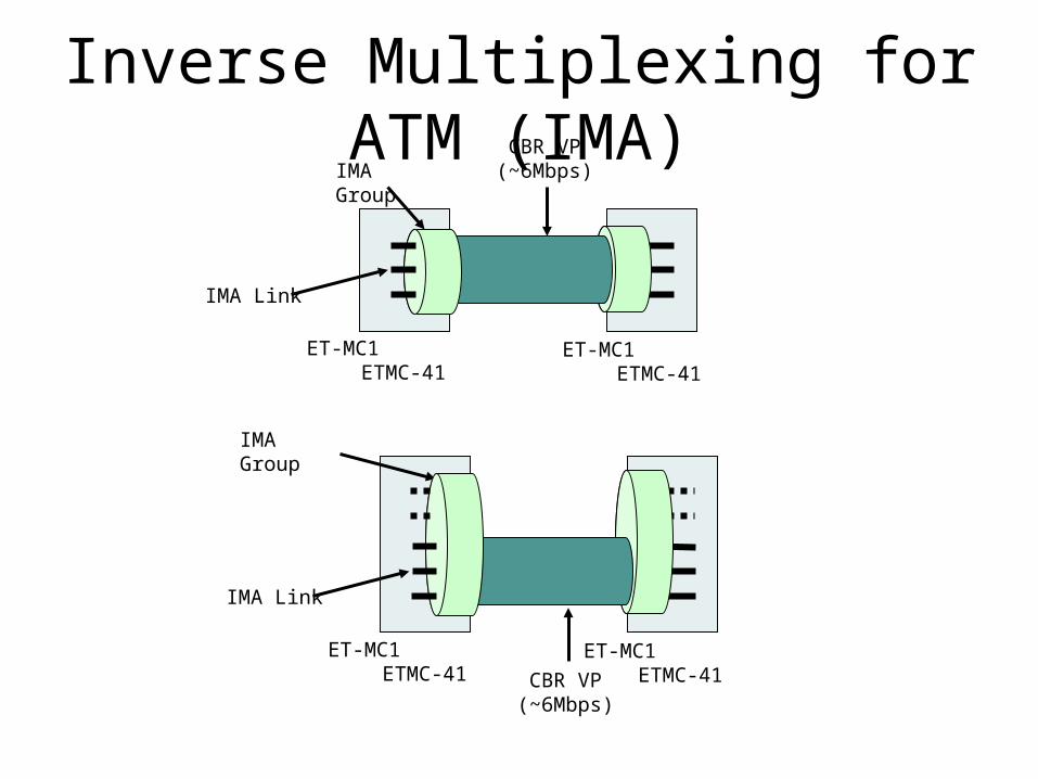
Inverse Multiplexing for ATM (IMA)
ET-MC1 ETMC-41
IMA Group
ET-MC1 ETMC-41
IMA Link
CBR VP (~6Mbps)
ET-MC1 ETMC-41
IMA Group
ET-MC1 ETMC-41
IMA Link
CBR VP (~6Mbps)
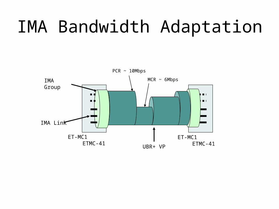
IMA Bandwidth Adaptation
ET-MC1 ETMC-41
IMA Group
ET-MC1 ETMC-41
IMA Link
UBR+ VP
PCR ~ 10Mbps
MCR ~ 6Mbps
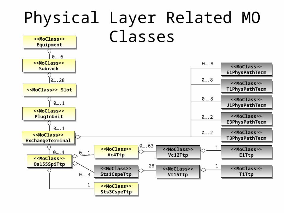
Physical Layer Related MO Classes
<<MoClass>> Subrack
<<MoClass>> Subrack
<<MoClass>> PlugInUnit
<<MoClass>> PlugInUnit
<<MoClass>> ExchangeTerminal
<<MoClass>> ExchangeTerminal
<<MoClass>> Os155SpiTtp
<<MoClass>> Os155SpiTtp
<<MoClass>> Sts1CspeTtp
<<MoClass>> Sts1CspeTtp
0….6
0….1
<<MoClass>> Slot<<MoClass>> Slot
0….28
0….1
0….8
0….1
<<MoClass>> E1PhysPathTerm
<<MoClass>> E1PhysPathTerm
<<MoClass>> T1PhysPathTerm
<<MoClass>> T1PhysPathTerm
<<MoClass>> J1PhysPathTerm
<<MoClass>> J1PhysPathTerm
<<MoClass>> E3PhysPathTerm
<<MoClass>> E3PhysPathTerm
<<MoClass>> T3PhysPathTerm
<<MoClass>> T3PhysPathTerm
<<MoClass>> E1Ttp<<MoClass>> E1Ttp
<<MoClass>> T1Ttp<<MoClass>> T1Ttp
<<MoClass>> Equipment
<<MoClass>> Equipment
<<MoClass>> Vt15Ttp
<<MoClass>> Vt15Ttp
<<MoClass>> Vc4Ttp
<<MoClass>> Vc4Ttp
<<MoClass>> Vc12Ttp
<<MoClass>> Vc12Ttp
0….4
0….3
0….63
28
1
1
0….8
0….8
0….2
0….2
<<MoClass>> Sts3CspeTtp
<<MoClass>> Sts3CspeTtp
1
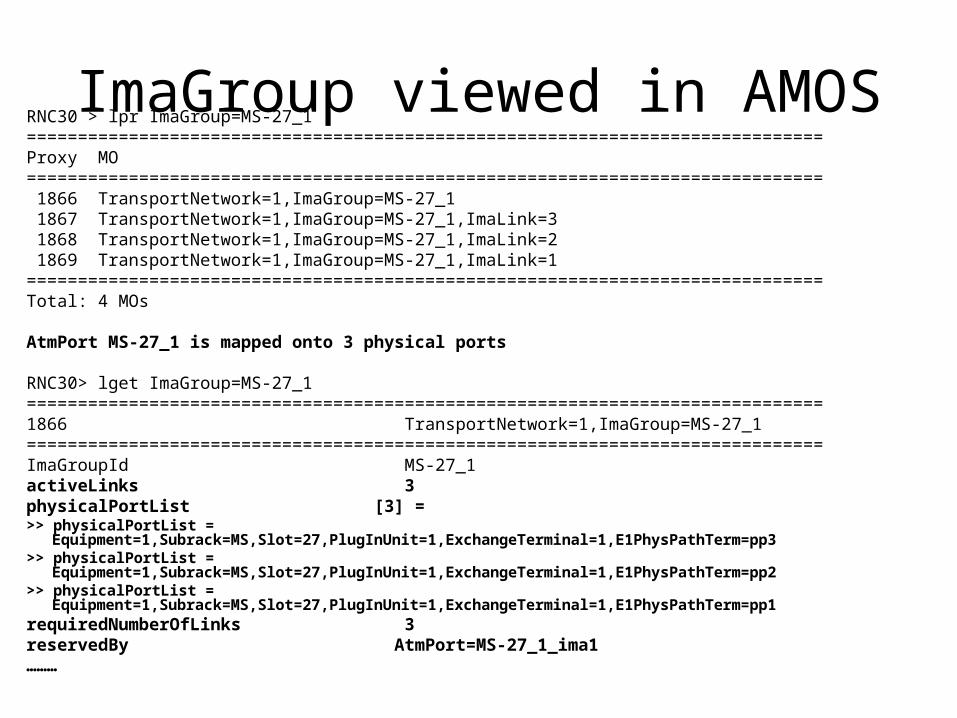
ImaGroup viewed in AMOSRNC30 > lpr ImaGroup=MS-27_1==============================================================================Proxy MO============================================================================== 1866 TransportNetwork=1,ImaGroup=MS-27_1 1867 TransportNetwork=1,ImaGroup=MS-27_1,ImaLink=3 1868 TransportNetwork=1,ImaGroup=MS-27_1,ImaLink=2 1869 TransportNetwork=1,ImaGroup=MS-27_1,ImaLink=1==============================================================================Total: 4 MOs
AtmPort MS-27_1 is mapped onto 3 physical ports
RNC30> lget ImaGroup=MS-27_1==============================================================================1866 TransportNetwork=1,ImaGroup=MS-27_1==============================================================================ImaGroupId MS-27_1activeLinks 3physicalPortList [3] = >> physicalPortList = Equipment=1,Subrack=MS,Slot=27,PlugInUnit=1,ExchangeTerminal=1,E1PhysPathTerm=pp3>> physicalPortList = Equipment=1,Subrack=MS,Slot=27,PlugInUnit=1,ExchangeTerminal=1,E1PhysPathTerm=pp2>> physicalPortList = Equipment=1,Subrack=MS,Slot=27,PlugInUnit=1,ExchangeTerminal=1,E1PhysPathTerm=pp1requiredNumberOfLinks 3reservedBy AtmPort=MS-27_1_ima1………
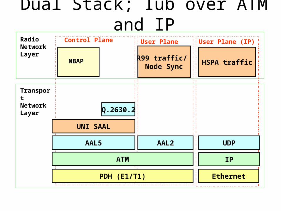
Dual Stack; Iub over ATM and IP
PDH (E1/T1)
NBAP
RadioNetworkLayer
Control Plane User Plane (ATM)
ATM
UNI SAAL
TransportNetworkLayer
R99 traffic/ Node Sync
AAL2
User Plane (IP)
Ethernet
IP
UDP
HSPA traffic
AAL5
Q.2630.2
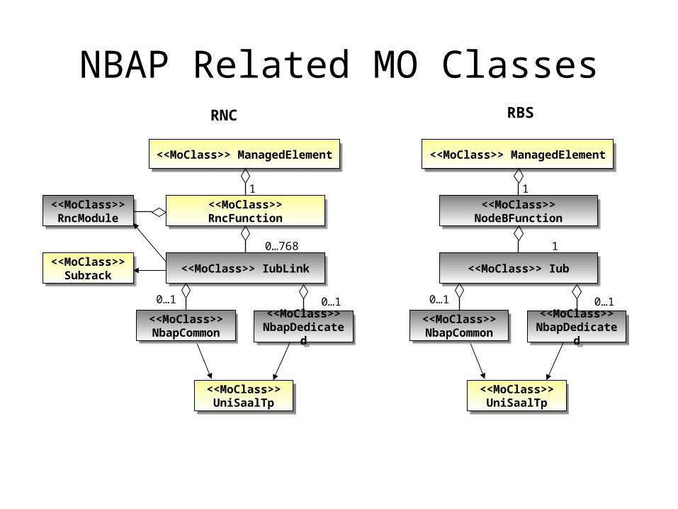
NBAP Related MO Classes
<<MoClass>> ManagedElement<<MoClass>> ManagedElement
<<MoClass>> RncFunction<<MoClass>> RncFunction
1
<<MoClass>> IubLink<<MoClass>> IubLink
0…768
<<MoClass>> NbapDedicated
<<MoClass>> NbapDedicated
<<MoClass>> NbapCommon
<<MoClass>> NbapCommon
0…10…1
<<MoClass>> UniSaalTp
<<MoClass>> UniSaalTp
RNC RBS
<<MoClass>> ManagedElement<<MoClass>> ManagedElement
<<MoClass>> NodeBFunction
<<MoClass>> NodeBFunction
1
<<MoClass>> Iub<<MoClass>> Iub
1
<<MoClass>> NbapDedicated
<<MoClass>> NbapDedicated
<<MoClass>> NbapCommon
<<MoClass>> NbapCommon
0…10…1
<<MoClass>> UniSaalTp
<<MoClass>> UniSaalTp
<<MoClass>> RncModule
<<MoClass>> RncModule
<<MoClass>> Subrack
<<MoClass>> Subrack
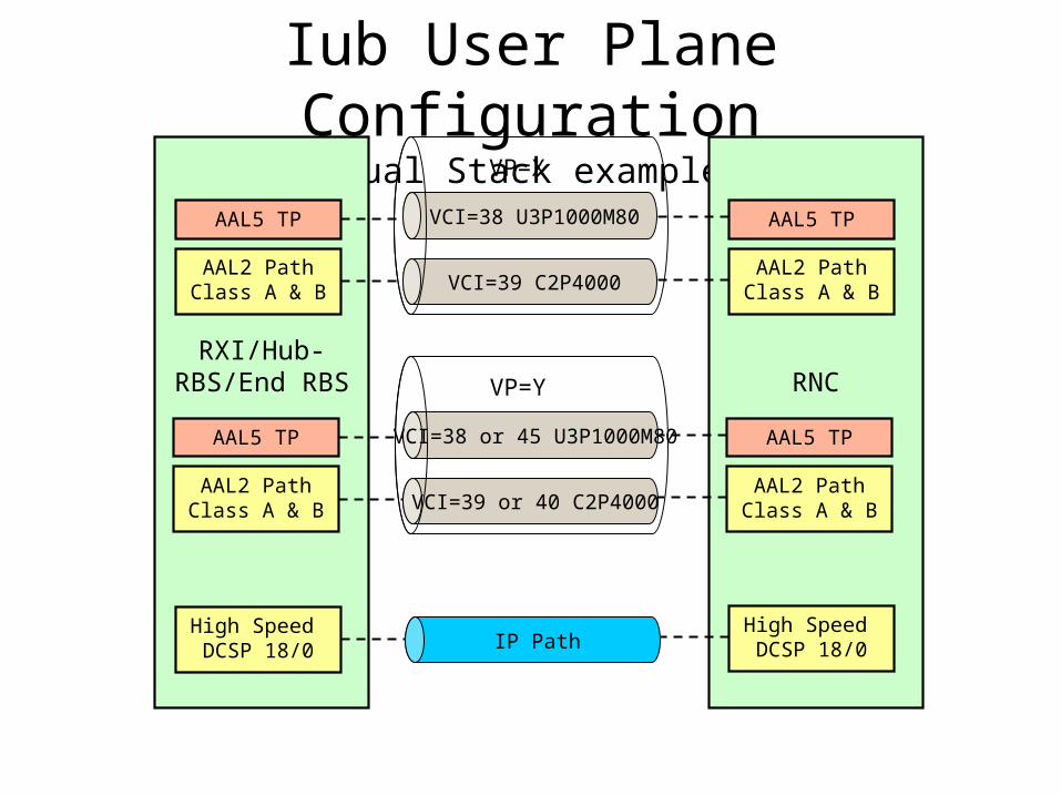
Iub User Plane ConfigurationDual Stack example
RXI/Hub-RBS/End RBS
AAL5 TP
AAL2 Path Class A & B
AAL5 TP
AAL2 Path Class A & B
High Speed DCSP 18/0
RNC
AAL5 TP
AAL2 Path Class A & B
AAL5 TP
AAL2 Path Class A & B
High Speed DCSP 18/0
VCI=38 U3P1000M80
VCI=39 C2P4000
VP=X
VCI=38 or 45 U3P1000M80
VCI=39 or 40 C2P4000
IP Path
VP=Y
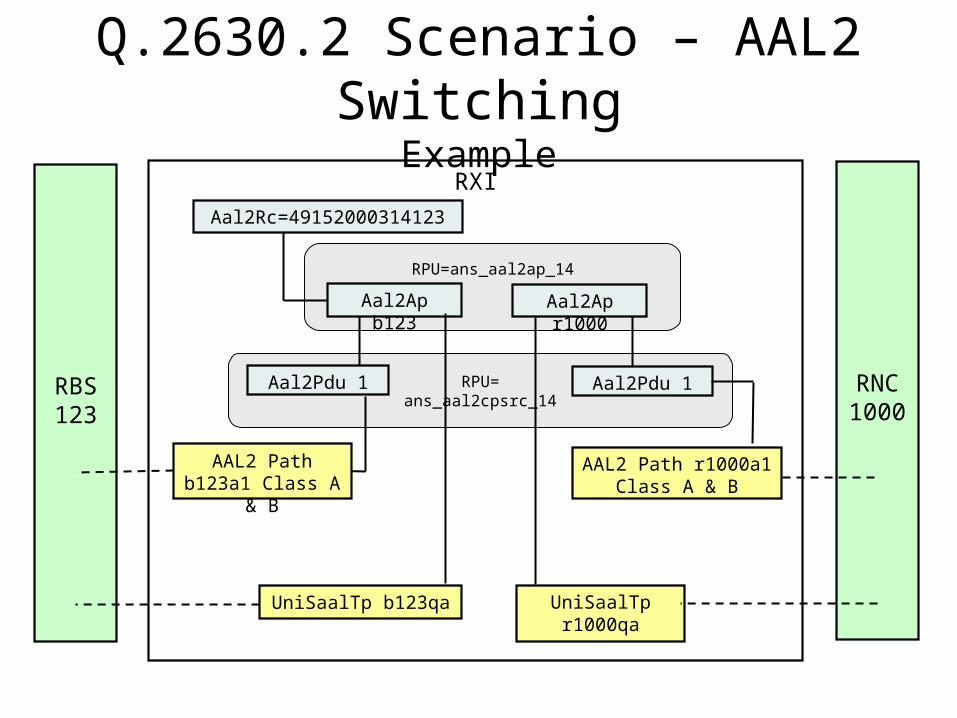
Q.2630.2 Scenario – AAL2 Switching
ExampleRXI
UniSaalTp r1000qa
AAL2 Path r1000a1 Class A & B
RNC1000
RPU=ans_aal2cpsrc_14
RPU=ans_aal2ap_14
Aal2Ap b123
Aal2Pdu 1
UniSaalTp b123qa
Aal2Rc=49152000314123
AAL2 Path b123a1 Class A & B
RBS123
Aal2Ap r1000
Aal2Pdu 1
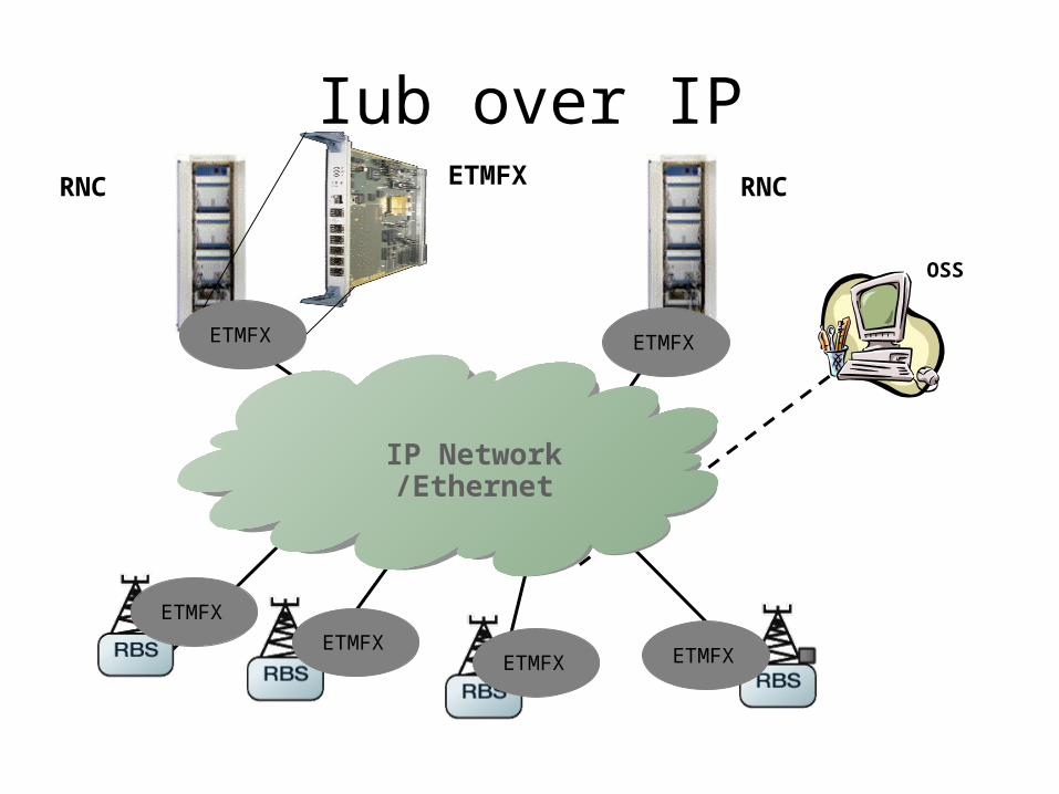
Iub over IP
IP Network/Ethernet
OSS
RNCRNC
ETMFX
ETMFX
ETMFXETMFX ETMFX
ETMFX
ETMFX
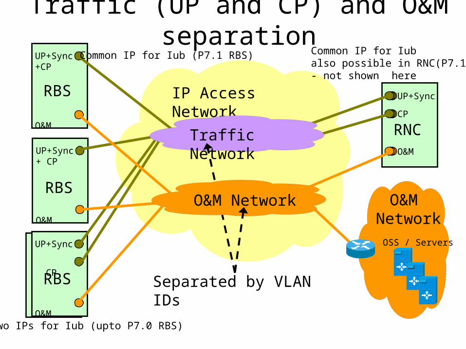
Traffic (UP and CP) and O&M separation
UP+Sync +CP
O&M
RBS
UP+Sync
CP
O&M
RBS
UP+Sync + CP
O&M
RBS
UP+Sync
RNCCP
O&M
O&M NetworkOSS / Servers
IP Access Network
Traffic Network
Separated by VLAN IDs
O&M Network
Common IP for Iub (P7.1 RBS)
Two IPs for Iub (upto P7.0 RBS)
Common IP for Iub also possible in RNC(P7.1)- not shown here
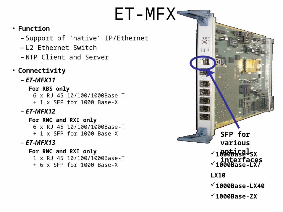
ET-MFX• Function
– Support of ‘native’ IP/Ethernet– L2 Ethernet Switch– NTP Client and Server
• Connectivity– ET-MFX11
For RBS only6 x RJ 45 10/100/1000Base-T + 1 x SFP for 1000 Base-X
– ET-MFX12 For RNC and RXI only
6 x RJ 45 10/100/1000Base-T + 1 x SFP for 1000 Base-X
– ET-MFX13 For RNC and RXI only
1 x RJ 45 10/100/1000Base-T + 6 x SFP for 1000 Base-X
SFP for various optical interfaces
1000Base-SX
1000Base-LX/LX10
1000Base-LX40
1000Base-ZX
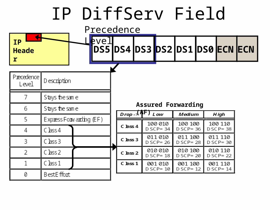
IP DiffServ Field
IP Header
Precedence Level
DS5 DS4 DS3 DS2 DS1 DS0 ECNECN
Assured Forwarding (AF)
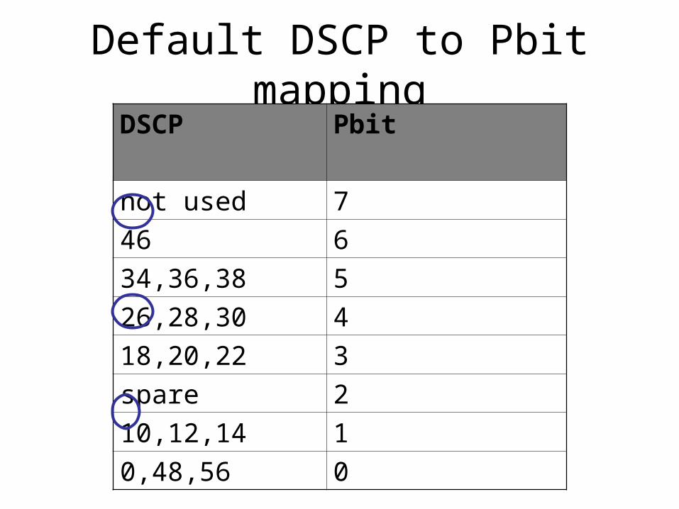
Default DSCP to Pbit mappingDSCP Pbit
not used 7
46 6
34,36,38 5
26,28,30 4
18,20,22 3
spare 2
10,12,14 1
0,48,56 0
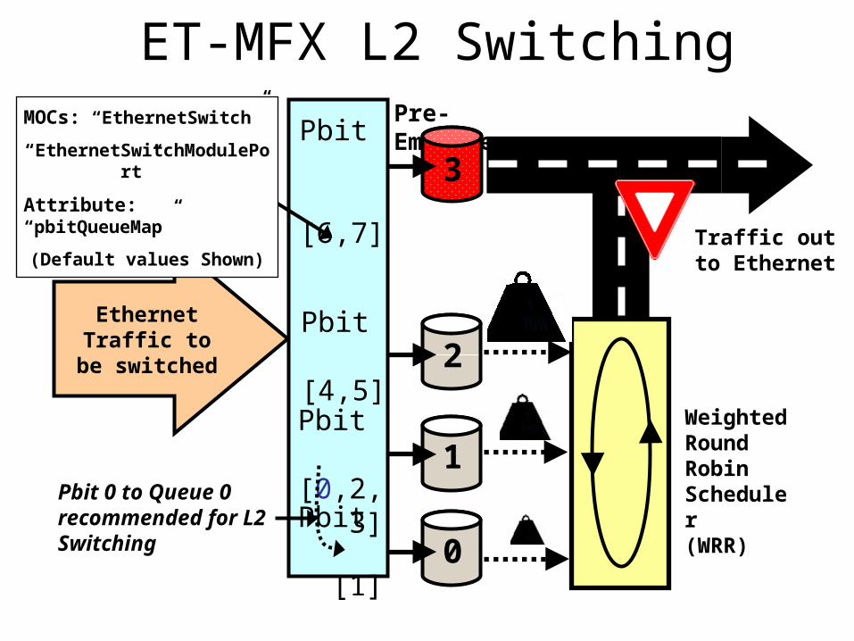
ET-MFX L2 SwitchingPre-Emptive
3
2
1
0
Traffic out to Ethernet
Ethernet Traffic to be
switched
Pbit [0,2,3]
Pbit [1]
Pbit [4,5]
Pbit
[6,7]
Weighted Round Robin Scheduler(WRR)
Pbit 0 to Queue 0 recommended for L2 Switching
MOCs: “EthernetSwitch”
“EthernetSwitchModulePort”
Attribute: “pbitQueueMap”
(Default values Shown)
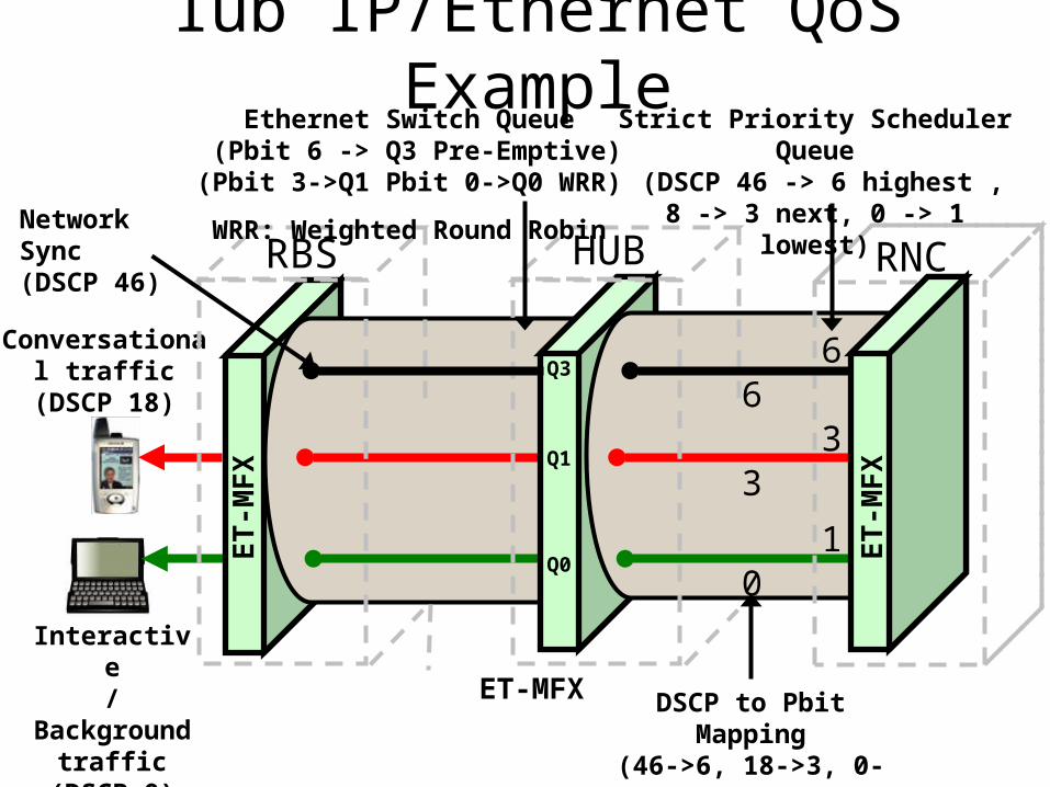
Iub IP/Ethernet QoS Example
Conversational traffic
(DSCP 18)
Interactive/Background
traffic(DSCP 0)
ET
-MF
X
ET-MFX
RBS HUB RNCNetwork Sync(DSCP 46)
ET
-MF
X
6
1
3
Strict Priority Scheduler Queue (DSCP 46 -> 6 highest , 8 -> 3
next, 0 -> 1 lowest)
DSCP to Pbit Mapping(46->6, 18->3, 0->0)
6
0
3
Ethernet Switch Queue (Pbit 6 -> Q3 Pre-Emptive)
(Pbit 3->Q1 Pbit 0->Q0 WRR)
WRR: Weighted Round Robin
Q3
Q0
Q1
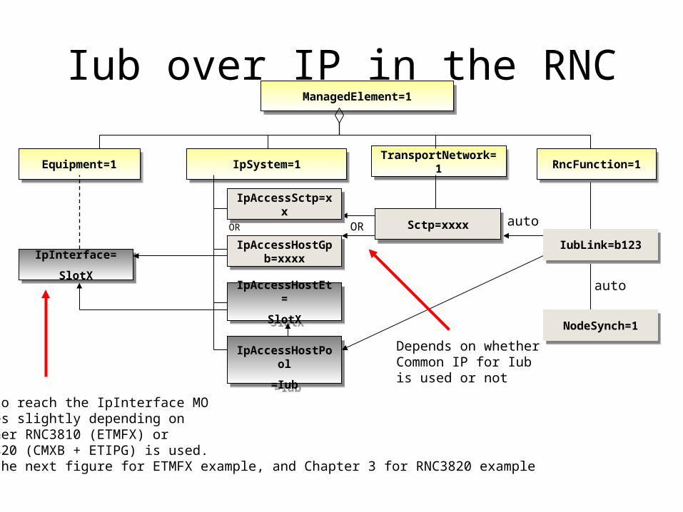
Iub over IP in the RNCManagedElement=1ManagedElement=1
IpInterface=
SlotX
IpInterface=
SlotX
Equipment=1Equipment=1
IpAccessHostPool
=Iub
IpAccessHostPool
=Iub
NodeSynch=1NodeSynch=1
IpAccessSctp=xxIpAccessSctp=xx
IpSystem=1IpSystem=1
IpAccessHostEt=
SlotX
IpAccessHostEt=
SlotX
Sctp=xxxxSctp=xxxx
IubLink=b123qaIubLink=b123qa
TransportNetwork=1TransportNetwork=1 RncFunction=1RncFunction=1
IpAccessHostGpb=xxxx
IpAccessHostGpb=xxxx
auto
OROR
IpAccessSctp=xxIpAccessSctp=xx
Sctp=xxxxSctp=xxxx
IpAccessHostGpb=xxxx
IpAccessHostGpb=xxxx
IpAccessSctp=xxIpAccessSctp=xx
IpAccessHostGpb=xxxx
IpAccessHostGpb=xxxx
IpAccessSctp=xxIpAccessSctp=xx
Sctp=xxxxSctp=xxxx
IpAccessHostGpb=xxxx
IpAccessHostGpb=xxxx
IpAccessSctp=xxIpAccessSctp=xx
NodeSynch=1NodeSynch=1
IubLink=b123qaIubLink=b123qa
NodeSynch=1NodeSynch=1
IubLink=b123IubLink=b123
How to reach the IpInterface MO varies slightly depending on whether RNC3810 (ETMFX) or RNC3820 (CMXB + ETIPG) is used.See the next figure for ETMFX example, and Chapter 3 for RNC3820 example
Depends on whether Common IP for Iub is used or not
auto
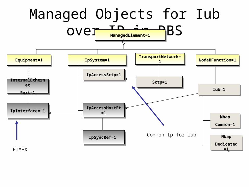
Managed Objects for Iub over IP in RBSManagedElement=1ManagedElement=1
IpInterface= 1IpInterface= 1
Equipment=1Equipment=1
IpAccessSctp=xxIpAccessSctp=xx
IpSystem=1IpSystem=1
IpAccessHostEt=1IpAccessHostEt=1
Sctp=xxxxSctp=xxxx
IubLink=b123qaIubLink=b123qa
TransportNetwork=1TransportNetwork=1 NodeBFunction=1NodeBFunction=1
IpAccessSctp=xxIpAccessSctp=xx
Sctp=xxxxSctp=xxxx
IpAccessSctp=xxIpAccessSctp=xxIpAccessSctp=xxIpAccessSctp=xx
Sctp=1Sctp=1
IpAccessSctp=1IpAccessSctp=1
IubLink=b123qaIubLink=b123qa
Nbap
Common=1
Nbap
Common=1
Iub=1Iub=1
Nbap
Dedicated =1
Nbap
Dedicated =1
InternalEthernet
Port=1
InternalEthernet
Port=1
Common Ip for Iub
ETMFX
IpSyncRef=1 IpSyncRef=1
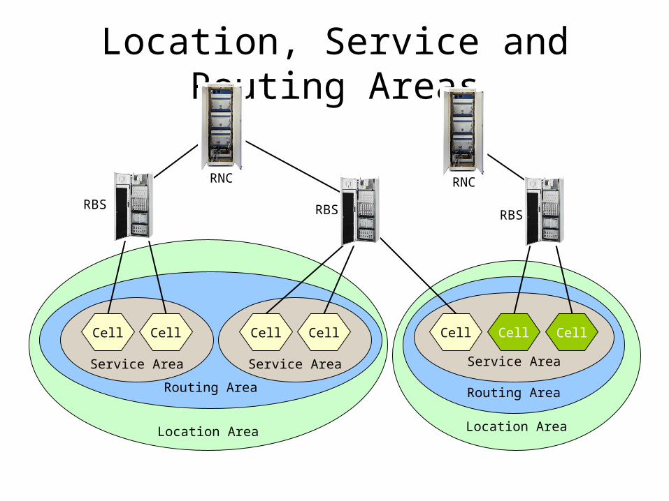
Location AreaLocation Area
Routing Area
Location, Service and Routing Areas
Service Area
CellCell
Service Area
CellCell
Routing Area
Service Area
CellCell Cell
RNC
RBS RBS RBS
RNC
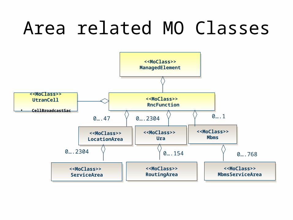
Area related MO Classes
<<MoClass>> ManagedElement
<<MoClass>> ManagedElement
<<MoClass>> RncFunction
<<MoClass>> RncFunction
<<MoClass>> LocationArea
<<MoClass>> LocationArea
0….47
<<MoClass>> ServiceArea
<<MoClass>> ServiceArea
0….2304
<<MoClass>> Ura
<<MoClass>> Ura
<<MoClass>> RoutingArea<<MoClass>> RoutingArea
0….154
0….2304
<<MoClass>> Mbms
<<MoClass>> Mbms
0….1
0….768
<<MoClass>> MbmsServiceArea
<<MoClass>> MbmsServiceArea
<<MoClass>> UtranCell
• CellBroadcastSac
<<MoClass>> UtranCell
• CellBroadcastSac
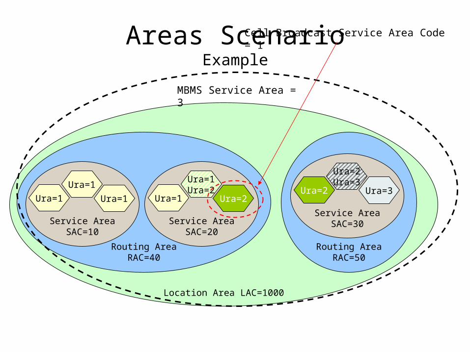
Location Area LAC=1000
Routing AreaRAC=50
Areas ScenarioExample
Routing AreaRAC=40
Service AreaSAC=10
Ura=1
Ura=1
Ura=1
Service AreaSAC=20
Ura=1
Ura=1Ura=2
Ura=2
Service AreaSAC=30
Ura=2
Ura=2Ura=3
Ura=3
MBMS Service Area = 3
Cell Broadcast Service Area Code = 1
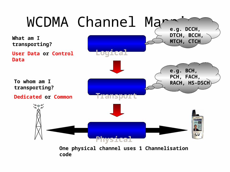
WCDMA Channel Mapping Logical
Physical
Transport
What am I transporting?
User Data or Control Data
To whom am I transporting?
Dedicated or Common
One physical channel uses 1 Channelisation code
e.g. DCCH, DTCH, BCCH, MTCH, CTCH
e.g. BCH, PCH, FACH, RACH, HS-DSCH
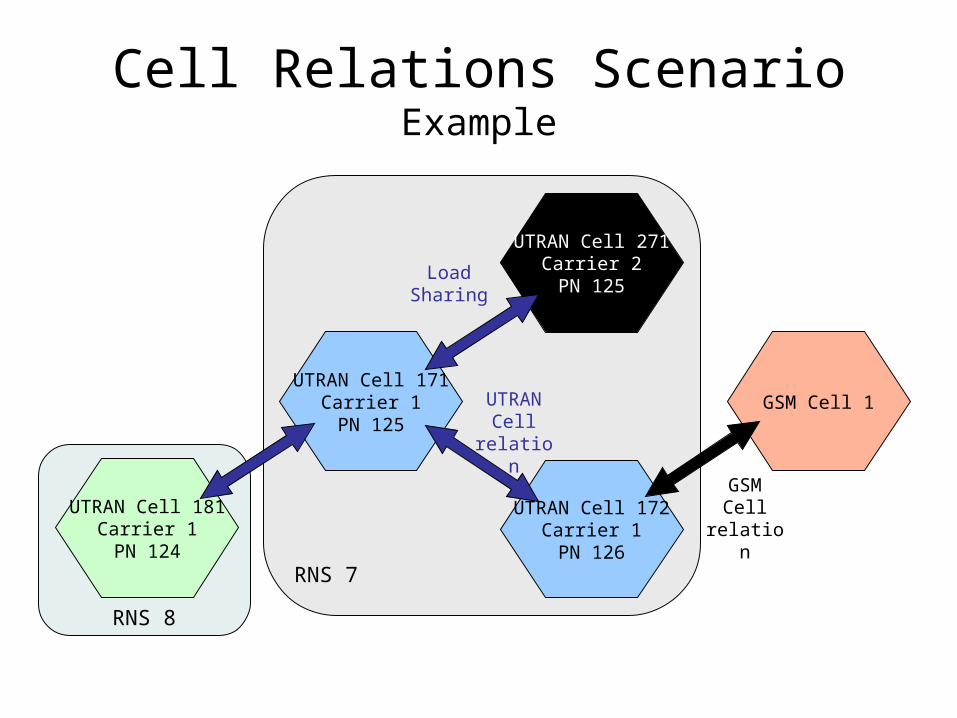
RNS 8
RNS 7
Cell Relations ScenarioExample
UTRAN Cell 171Carrier 1PN 125
UTRAN Cell 172Carrier 1PN 126
UTRAN Cell 181Carrier 1PN 124
GSM Cell 1UTRAN Cell
relation
GSM Cell relation
UTRAN Cell 271Carrier 2PN 125
Load Sharing
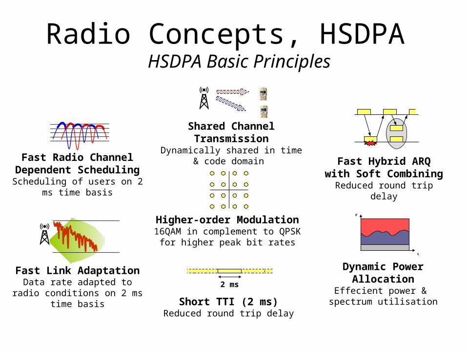
Radio Concepts, HSDPA HSDPA Basic Principles
Shared Channel TransmissionDynamically shared in time & code
domain
Higher-order Modulation16QAM in complement to QPSK for
higher peak bit rates
2 ms
Short TTI (2 ms)Reduced round trip delay
Fast Hybrid ARQ with Soft Combining
Reduced round trip delay
Fast Radio Channel Dependent Scheduling
Scheduling of users on 2 ms time basis
Fast Link AdaptationData rate adapted to radio
conditions on 2 ms time basis
t
P
Dynamic Power AllocationEffecient power & spectrum utilisation
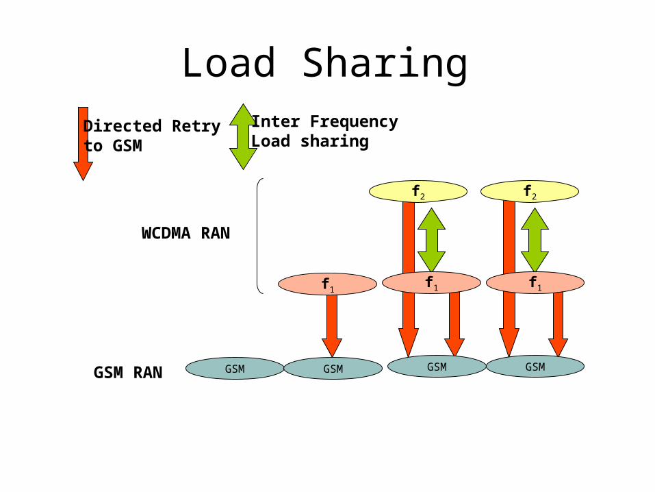
Load Sharing
f1
GSM GSM GSM GSM
WCDMA RAN
Directed Retry to GSM
Inter FrequencyLoad sharing
GSM RAN
f1 f1
f2f2
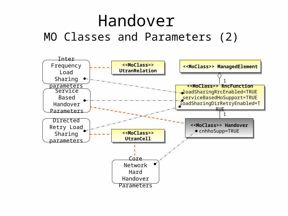
Handover MO Classes and Parameters (2)
<<MoClass>> ManagedElement<<MoClass>> ManagedElement
<<MoClass>> Handover cnhhoSupp=TRUE
<<MoClass>> Handover cnhhoSupp=TRUE
1
1
<<MoClass>> UtranCell
<<MoClass>> UtranCell
<<MoClass>> UtranRelation
<<MoClass>> UtranRelation
Inter Frequency
Load Sharing parameters
Core Network Hard Handover
Parameters
<<MoClass>> RncFunction loadSharingRrcEnabled=TRUE serviceBasedHoSupport=TRUE
loadSharingDirRetryEnabled=TRUE
<<MoClass>> RncFunction loadSharingRrcEnabled=TRUE serviceBasedHoSupport=TRUE
loadSharingDirRetryEnabled=TRUE
Directed Retry Load Sharing parameters
Service Based Handover
Parameters
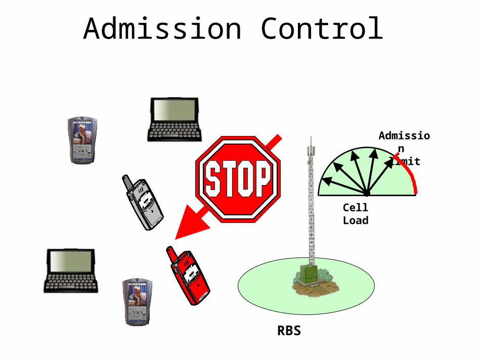
Admission Control
RBS
Cell Load
Admission
limit
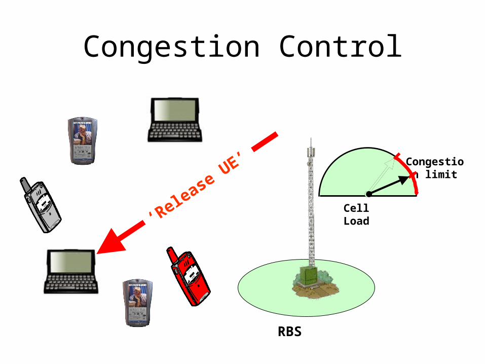
Congestion Control
RBS
Cell Load
Congestion limit
‘Release U
E’
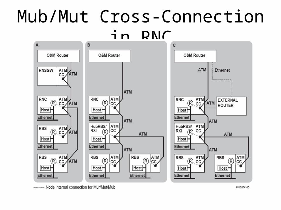
Mub/Mut Cross-Connection in RNC
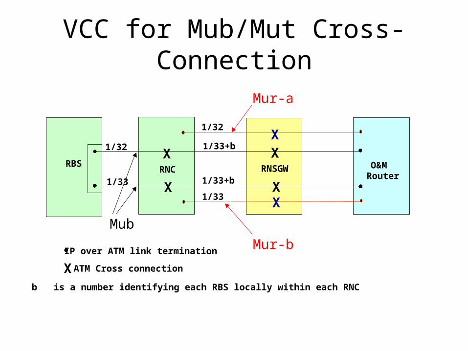
RBSRNC RNSGW O&M
RouterXX
X XX
X
IP over ATM link termination
X ATM Cross connection
1/32
1/33
1/33
1/32
1/33+b
1/33+b
Mur-b
Mur-a
b is a number identifying each RBS locally within each RNC
Mub
VCC for Mub/Mut Cross-Connection
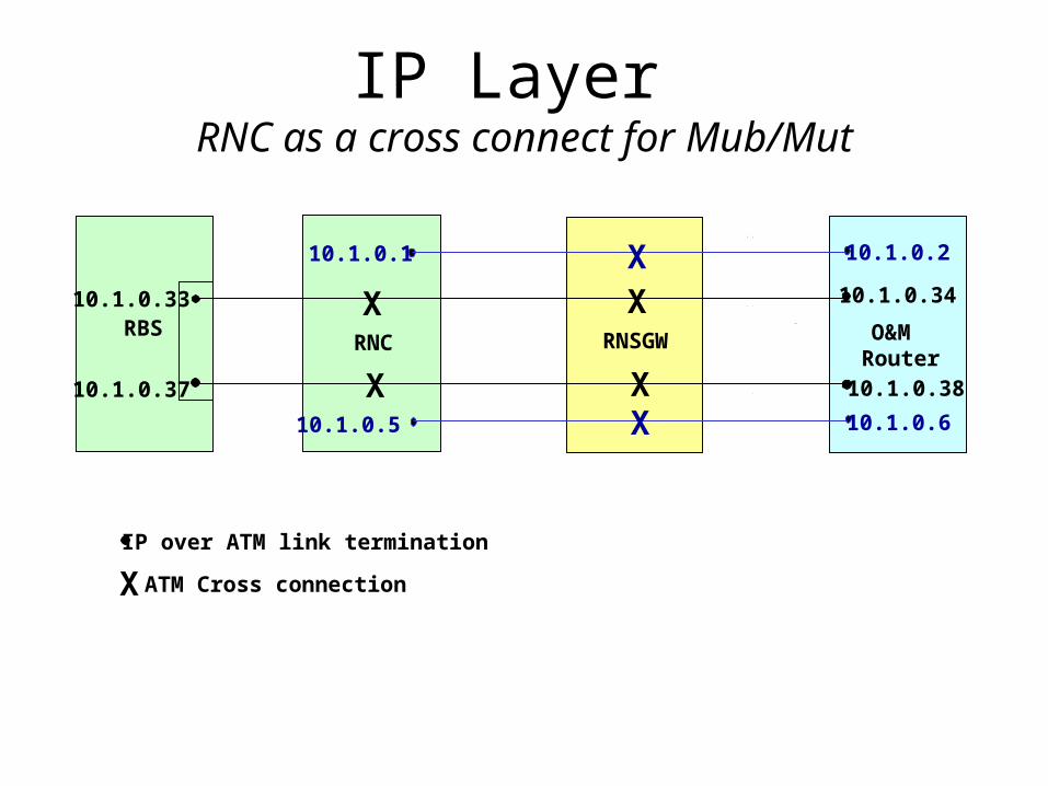
IP Layer RNC as a cross connect for Mub/Mut
RBSRNC RNSGW O&M
RouterXX
X XX
X
IP over ATM link termination
X ATM Cross connection
10.1.0.33 10.1.0.34
10.1.0.37 10.1.0.38
10.1.0.1 10.1.0.2
10.1.0.5 10.1.0.6
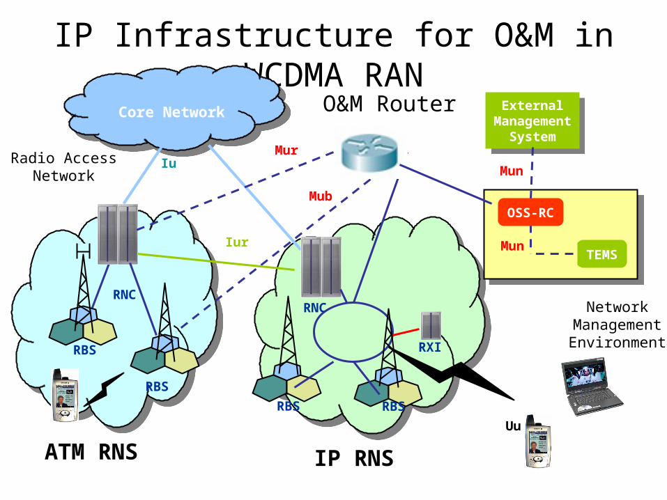
IP Infrastructure for O&M in WCDMA RAN
Radio AccessNetwork
Iu
Iur
Mub
Mur
Uu
ExternalManagement
System
ExternalManagement
System
Mun
Mun
NetworkManagementEnvironment
OSS-RC
TEMS
Core Network
RNC
RXI
RNC
RBS
RBS
RBS RBS
ATM RNS IP RNS
O&M Router