Embed Size (px)
Citation preview

EFINS-66-49
AM INSTRUMENT FOR L'U'NAR SURFACE CHEMICAL ANALYSIS
Anthony Turkevich, Karlfried. Knolle Enrico Fermi Institute for Nuclear Studies
and. Department of Chemist.ry
University of Chicago, Chicago, Illinois
Richard. E. Emmert, Wayne A. And.erson Laboratory for Astrophysics and. Space Research of the Enrico Fermi Institute for Nuclear Stud.ies
University of Chicago, Chicago, Illinois
James H. Patterson Chemistry Division
Argonne National Laboratory, Argonne, Illinois
and.
Ernest Franzgrote Jet Propulsion Laboratory, Pasad.ena, California
Submitted. to
The Review of Scientific Instruments
May 1966 . . -
0 - - r - - GPO PRICE $
CFSTl PRICE(S) $ p67 ID 13228
! /9e757757 > *'
(ACCESSION NUMBER1
4q- t e (PAGTOI
Har . w p y (HC)
CATEGORY) (NASA CR OR TUX On AD NUMBER) Microfiche (MF) ,A
W 653 July 66
https://ntrs.nasa.gov/search.jsp?R=19670003899 2018-06-13T16:49:58+00:00Z

c
* An Instrument for Lunar Surface Chemical Analysis
Anthony Turkevich, Karlfried. Knolle Enrico Fermi Institute for Nuclear Studies
and. Department of Chemistry
University of Chicago, Chicago, Illinois
Richard. E. Emmert,* Wayne A. And.erson Laboratory for Astrophysics and. Space Research of the Enrico Fermi Institute for Nuclear Studies
University of Chicago, Chicago, Illinois
t
James H. Patterson Chemistry Division
Argonne National Laboratory, Argonne, Illinois
and
Ernest Franzgrote Jet Propulsion Laboratory, Pasad.ena, California
An instrument has been d.esigned. and. constructed.
which utilizes the interactions with matter of mono-
energetic alpha particles for surface chemical analysis.
The source of alpha particles is a radioactive nuclid.e,
such as Cm242. The energy spectra of backscattered,
alpha particles are measured. with semiconductor d.etec-
tors. Other d.etectors (with gold foils over them to
eliminate alpha particles) register protons from (a,p)
reactions. Transistorized. electronics pr0vid.e 128-
channel pulse-height analyzers for both alpha and pro-
ton spectra. The specific unit d.esigned. for the
Surveyor Lunar Mission weighs less than 4 kg. and uses
less than 1.3 watts.

-2-
I. INTRODUCTION
The interactions with matter of alpha particles from
radioactive sources can be made the basis of an analytical
technique. The principles of this method. have been d.escribed.
elsewhere. 'j2
spectra of alpha particles elastically scattered backward. and.
the spectra of protons prod.uced. by (a,p) reactions, to d.ed.uce
the chemical composition of the sample being exposed. to the
alpha particles.
particles for such a purpose is an alpha rad.ioactive nuclide,
such as Cm242. The energy spectra of the alpha particles and.
protons are efficiently d.et ermined., using semiconductor d.et ec - tors and transistorized electronics.
d.escribes a prototype instrument constructed. accord.ing to these
principles and. d.esigned. for the chemical analyses of lunar and.
planetary surfaces. The electronics of this instrument have
been ad.apted. from those employed in the University of Chicago
cosmic-ray programs.
It takes ad.vantage of the characteristic energy
A convenient source of monoenergetic alpha
The present report
Because of requirements peculiar to the proposed lunar
mission, the system is d.ivid.ed. into two functional blocks: a
d.ep1oyable sensor head. ( "Head. Unit") and. a d.igita1 electronics
system ("Electronics Unit").
placed d.irectly on the lunar surface. It contains the alpha
radioactive sources, semicond.uctor d.etectors, and. the linear
portion of the electronics (through height-to-time signal con-
version). The d.igit.al electronics unit contains a gated clock
The sensor head. is d.esigned. to be

-3-
for pulse wid.th to digital conversion, temporary d.ata storage,
command. switching, power distribution, and. spacecraft interface
circuitry. Figure 1 shows pictures of the two parts of the
first prototype instrument which is d.escribed. in this report,
together with the test rack used. for checking its behavior.
The total weight of the two components of this unit is 3.5 kg.,
with 1.4 kg. of this being the weight of the d.eployable head..
The power consumption of the instrument is less than 1.3 watts -
most of it in the electronics package. It is d.esigned. to oper-
ate from a 24-volt supply. Details of the sub-systems, as well
as d.ata on the performance, are provid.ed. in the following sections.
11. "HEAD" UNIT
A. General Characteristics
The "Head." Unit of the instrument (see Fig. 1) is a box
13.3 em by 17.1 em by 11.7 ern high, containing the alpha sources,
the d.etectors, and part of the transistorized electronics. It
has a circular opening in the bottom 10.8 em in diameter. The
sample is examined. through this opening. Figure 2 shows a view,
through the bottom opening, of the head unit. Figure 3 shows
some d.etails of construction. In a lunar operation, the head
unit would, be d.eployed. on to the original (or on to a prepared.)
surface of the moon. In laboratory studies, the head unit is
kept in a vacuum and. samples are presented. to it through a vacuum
lock.

.
t
-4-
The components of the head. are designed to allow the
sample to be uniformly irradiated with a collimated, stream of
alpha particles from the source hold.ers. Alpha particles scat-
tered backwards from the sample are detected by the two energy
sensitive semiconductor d.etectors (alpha detectors). Protons
prodxced. by the alpha particles in the sample are d.etected. by
the four symmetrically placed proton detectors.
B. Sources
The alpha particles come from six collimated source
hold.ers. The source hold.ers are separate units that are d.esigned.
to be inserted from the top of the head turret for ease of
replacement and. to minimize the danger of contamination of the
part of the instrument that can be seen by the detectors. The
d.etails of the construction are shown in Fig. 4. The collimators
are mad.e of stainless steel. The dimensions in these collimators
are very critical, since they d.etermine the direction of the
alpha particles so that they strike only the sample aperture
5.7 em away. Likewise, very important are pumping passageways
which allow the air to be pumped. out from the space between the
sources and. the collimator faces. This air is conducted. to the
top of the turret head., again to minimize the d.anger of contam-
ination of the sensitive parts of the instrument.
Across the face of each collimator is placed a thin film
to prevent recoils from the alpha source from reaching the sam-
ple area or the sensitive part of the instrument. This film
must be thick enough to stop the recoiling atoms but not thick

?
4
-5-
enough to d.egrade the energy or homogeneity of the source.
Aluminum 0xid.e films of approximately 1000 8 thickness have
been found. to be stable to the rad.iation from lo1’ d./m of Cm
for a period. of six months. Organic films appear to be much
more susceptible to radiation damage. The collimator, together
* 24 2
with the protective film, is a replaceable section of the source
hold.er (see Fig. 4). The id.ea1 isotope for the sources would. emit alpha part-
icles with a single energy that would be greater than 5.8 MeV.
It should have no gamma activity. Its half life would be about
two years and that of its first daughter at least 10 3 years. It
should be available commercially in curie quantities, free of
non-volatile and rad.ioactive impurities. Chemically, it should
be readily purified from all other non-volatile elements and.
give stable, ad.herent d.eposits on plates at alpha-activity levels
up to 0.5 curie/cm . 2
A brief trial of Po21o, which is commercially available
and practically monoenergetic, with a non-radioactive daughter,
was aband.oned because contamination problems were d.ifficult to
control. Cm 242 was found, to fit the requirements as closely as
any available isotope.
The only other one of significance is 44 KeV lower in energy,
Its main peak has an energy of 6.11 MeV.
with about one third. its intensity. Although the ratio of gamma
to alpha events is only about 4.10-~ because of internal conver-
sion, there is enough low-energy gamma emission associated. with
the high level of alpha activity to require consid.eration as a * Procured. from the Rauland. Corp ., Chicago, Illinois.

, -6-
source background in the lower energy channels of the present
system. Likewise, a small amount of spontaneous fission gives
rise to a few neutrons. The lower than optimum half life (162
d.ays) makes it necessary to correct for d.ecay of the sources for
experiments lasting longer than a few d.ays. This also limits
the usef-icl life of a source because of its d.ecrease in strength,
and. because of the growth of its d.aughter Pu238, with a half life
of 89 years.
Cm242 is not commercially available at this time but may
be prepared. in curie quantities by irradiation of Am 241 in a nuclear reactor, followed by chemical separation of the curium. 3
The concentrations of the longer lived. isotopic impurities,
Cm 243 and. Cm244 (half lives 32 years and. 18 years, respectively),
are the principal limitation to the useful life of curium from a
given irradiation, as their activity becomes relatively more
important with the d.ecay of the Cm242.
low as possible by irrad.iating a large amount of free of
Am243, with the minimum number of neutrons necessary to obtain the
d.esired. quantity of Cm242.
Their presence is kept as
Chemically, curium can be manipulated.
without difficulty, and. the sources obtained. are ad.herent enough
so that no losses have been observed. through shaking, air cur-
rents, evaporation, or creeping. However, activity can be rubbed.
off readily. These sources originally have energy spectra with
full wid.ths at half maximum of 0.5 - 2.0%. However, unless the
sources are protected. from atmospheric humid.ity, they d.eteriorate,
with the wid.ths reaching - 3$ in a week, and. low-energy tails
appearing in the spectra.

" .
The sources for the present instrument were prepared by
evaporating the chemically purified. curium onto stainless steel
plates which were then inserted. into the source holders. Tne r
usable area of the sources is 0.066 cm'.
the alpha particles get out through the collimating system. The
original smirce strength of the ilnLd.ivid.ual six sources used. in
most of the work with this instrument was between 1 and. 3-lO1O d./m.
If larger source strengths than the ones employed here are to be
used, it might be necessary to reduce interference by constructing
the turret in the vicinity of the sources out of a heavy material,
such as Hevi-met, (a tungsten alloy).
About 2.2 per cent of
C. The Scattered. Alpha M0d.e of the Instrument
This m0d.e of the instrument is d.esigned. to d.etect and
d.etermine the energy of alpha particles scattered. by the sample.
Although the energy of such scattered. alpha particles is not a
sensitive function of the angle in the backward. d.irectionY2 the
d.istances from the source to the sample and. the sample to the
alpha detector were made relatively large (5.7 em), at the cost of increased measurement time, to minimize possible effects of
surface roughness. At a scattering angle of 180°, all such
effects should. rigorously disappear. In the present instrument,
the average scattering angle was 174.5", with a range of one
d.egree on each sid.e of this value.
4
The two alpha d.etectors are of the silicon surface bar-
rier type. Details of construction are shown in Fig. 4. Masks
in front of the d.etectors, with an opening of 0.20 ern , prevent 2
C
c
. -8-
alpha particles from reaching the edge areas of non-uniform
sensitivity, and also keep the detectors from seeing the tips
of the source collimators which might be contaminated,.
The d.etectors are reverse-biased. to produce an active
d.epth ( - 5Op), d.eep enough to generate full energy pulses from
7-MeV alpha particles, but not d.eep enough for significant energy
d.eposition by protons or electrons, either from the sample or
from cosmic rays. Such d.etectors, prepared. especially for this
instrument, are operated. with bias voltages of 2.5 - 3.5 volts.
Provision is available for a very thin film to be mounted. over
the d.etectors to protect them from contamination, or, if neces-
sary, to cut d.own the light entering the d.etectors (these
d.etectors are quite photosensitive).
D. The Proton Mode of the Instrument
The proton m0d.e of the instrument was d.esigned. to mea-
sure the number and. energy of protons from (c1,p) reactions in
certain elements. The number of protons is usually smaller than
the number of scattered. alpha particles, both because of the
smaller number of elements producing protons, the usually intrin-
sically lower yield. of (a,p) reactions, and. because the elements
prod.ucing protons are frequently present in low abund.ance. The
total area of the four proton d.etectors is, therefore, mad.e as
large as possible ( - 4 em ), and. they are placed. closer to the
sample than are the alpha d.etectors. Fortunately, because of
the longer range in materials of protons, and because not as much
energy or angular resolution is need.ed. in the proton system, such
2

-9-
a geometr ical arrangement i s acceptable . D e t a i l s of cons t ruc t ion
of t h e proton d e t e c t o r system a r e shown i n Fig. 4. The average
angle a t which protons a r e d.etected i s 145O, but t h e r e i s a var-
i a t i o n of a t l e a s t 20' about t h i s value.
I n ord.er no t t o de tec t sca t te red . a lpha p a r t i c l e s i n t h e
pro ton mod.e, enough absorber (21.1 f 0.4 mg/cm2 of gold.) i s
placed. over t he de t ec to r s t o absorb out even alpha p a r t i c l e s w i t h
t h e o r i g i n a l energy.
because protons a r e prod.uced. i n it by sca t te red . alpha p a r t i c l e s . )
The th ickness of t h e absorbers must be matched s u f f i c i e n t l y t o
make t h e four proton d.etectors have t h e same energy response t o
pro tons . Likewise, v a r i a t i o n i n t h e th ickness must be minimized
t o avoid d.egradation of t h e energy r e s o l u t i o n of t h e system.
(Aluminum i s no t s u i t a b l e f o r t h i s purpose
I n view of t h e low proton r a t e s expected. f rom t y p i c a l
rocks, and. t h e expected. cosmic-ray background., t h e proton d.etectors
a r e backed up by guard. d.etectors ( s e e Fig. 4 ) e l e c t r i c a l l y con-
nected i n such a way t h a t a p a r t i c l e going through both d e t e c t o r s
w i l l no t be reg is te red . . This ant i -coincid,ence shield.ing does not
a f f e c t protons from t h e sample, s ince they do n o t have enough
energy t o ge t through t h e lower de t ec to r .
The proton m0d.e o f the instrument has been t h e more d i f -
f i c u l t t o opera te . The four d .e tectors a re , of course, harder t o
match i n energy response than a r e t h e two a lpha d e t e c t o r s . I n
ad.dit ion, t h e l a r g e r e l e c t r i c a l capac i ty 1ead.s t o a higher no i se
l e v e l i n t h e f i r s t s t a g e of the e l e c t r o n i c s . Perhaps t h e most
s e r ious ope ra t iona l d i f f i c u l t y i s t h e l a c k of a monitoring method

-10-
to excite the system through the absorbers.
stand.ard (having 8.78 MeV alpha particle) has been only partially
successful: the energy of this alpha particle after going through
the absorber is d.egrad.ed. so much that the peak is broad. and. is
only a qualitative monitor of the behavior of the system.
Use of a Th 2 28
A firial d.lfflcultjr with the pmton system arises f rom the
high voltage need.ed. to prod.uce a sensitive d.epth in the silicon
d.etector large enough to absorb 6 MeV protons (even after going
through the absorber). The d.etectors used require 70 volts to
get a sensitive d.epth of 200 microns. Changes in leakage cur-
rent in the electronics can affect the voltage across the detector
sufficiently to change the d.epletion d.epth and. so the appearance
of the high-energy part of the proton spectrum. Recent mod.els of
this instrument use lithium-drifted. d.etectors, which require much
lower bias voltages, and.which can be mad.e to be much more stable
at the temperature extremes5 anticipated. on the moon.
I11 ELECTRONICS
A. Over-all Design
The electronic system associated. with the instrument is
d.esigned. to pr0vid.e bias voltages and. thresho1d.s for the semi-
conductor d.etectors, linear amplification for their output pulses,
two 128-channel pulse-height analyzers which convert the analogue
output of the amplifiers into seven binary digits, three buffer
registers for temporary storage of this information, and provision
for readout of the register content into the spacecraft trans-
mission system. The electronics also provides means of blocking

.
-11-
the outputs of the ind.ivid.ua1 d.etectors by command (from earth)
in case of malfunction. In the proton system, the electronics
also includes a rejection system for pulses in the d.etector when
they are coincid.ent with a pulse in a guard. detector.
These electronics were adapted. from circuits originally r
b d.esigned. for cosmic-ray studies on satellites. Weight mid. power
consid.erations and. established, experience were given over-riding
priority in the design.
buffer registers) is provid.ed.; the instrument is d.esigned. for the
transmission of the characteristics of each pulse, essentially in
real time, d.own to earth for accumulation and further data anal-
ysis on the ground..
in the alpha m0d.e and 0.1 per second. in the proton m0d.e) and with
the band widths available for transmission (2200 bits/sec and.
550 bits/sec, respectively), this d.esign, incorporating, as it
d.oes, some time smoothing of the d.ata, appears ad.equate for the
nominal operating situation on the moon.
Thus, no local memory (other than the
At the d.ata rates expected. ( - 1 per second.
B. Block Diagrams
The electronics of the instrument are partly in the head
unit and partly in the electronics package. The portion in the
head. consists primarily of the linear circuitry. A block d.ia-
gram of this portion is shown in Fig. 5. This electronics con-
verts a signal output from the semicond.uctor detectors, after
amplification by a charge-sensitive amplifier, into an analogue
pulse whose d.uraDion is proportional to the energy d.eposited. in
the d.etector (after subtraction of a threshold. amount - equivalent

?
-1 2-
to about 400 KeV).
Hutchinson-Scarrott type. This analogue output is transmitted
over an - 10 ft. cable to the electronics package in the space- craft. A 6-MeV event in a detector produces a pulse around one
milli see long.
The height-to-time converter is of the
At the Mixer circilit in the head, the outputs =f the two
alpha detectors are combined before further common processing.
At this point, the output of either detector can be blocked by
command from earth in case of malfunction.
A separate, parallel, electronics system handles the pro-
The outputs of the four pro- ton detector outputs (proton mode).
ton detectors are combined at the Mixer stage. Associated with
each proton detector is a guard detector. The output from any
one of these guard detectors, if greater than a threshold, blocks
the linear gate for 3 psec, while any associated signal from a
proton detector is delayed f o r - 2 psec via a delay line. This
prevents the processing of events coincident with pulses from the
guard detectors. In the proton mode, the separate switches block
the outputs of both a particular detector and its guard. - In addition to this electronics, the head contains a
primitive temperature control system. This consists, firstly, of
a temperazure sensor which provides a temperature reading of the
electronics-detector complex and transmits this information to
earth. In addition, there is a 5-watt heater that can be turned
on either in a programmed manner, or by earth command, if the
temperature falls below a pre-arranged level ( - O'C).

L
-13-
The electronics package, on the spacecraft, receives the
analogue signal from the head, converts it into digital form,
provid.es a small amount of d.ata smoothing, and. then routes the
digitized information about a given event to the spacecraft
telemetry system for transmission d.own to earth. Again, there
are completely parallel systems for both alpha and proton mod.es
of the instruments. In ad.d.ition, the electronics package con-
tains the power supplies and. the control logic for the instrument.
A block diagram of the components of the electronics package is
shown in Fig. 6.
The output of the instrument in both alpha and proton
mod.es is a nine-bit word, of which seven bits id.entify which of
128 possible channels represent the energy of the registered.
event. Two extra bits are ad.d.ed., one before transmission to
id.entify the start of the word. and. one at the end. of each word.,
as a parity check on transmission errors. The transmission rates
are 2200 bps for the alpha m0d.e and 550 bps for the proton m0d.e.
The energy scale of the instrument is about 55 KeV per channel,
with a threshold. of about 400 KeV.
with energy greater than the range of the analyzers are routed. to
channel 126 (overflow channel) .
Pulses corresponding to events
IV. PERFORMANCE OF THE INSTRUMENT
This prototype instrument has now been in operation for
more than two years. Except for two early detector failures, the
performance has been reliable. During the period of active use - during the first nine months after completion - there were minor
drifts in the gain and. offset of the alpha system. The changes
could be monitored. using a monochromatic source of alpha particles.
No changes were observed. in the proton system d.uring this period..

-14-
An instrument d.esigned to operate on the lunar surface
should. be capable of satisfactory performance und.er a wide range
of temperature conditions.
ated. at temperatures from -40°C to +50°C.
changes in the detector-electronics system were somewhat larger
than desirable ( - 8% in the alpha m0d.e and. - 5% in the proton mode) over this temperature range.
changes in response at - 6 MeV, d.epend.ing on the number of d.e t ec tor s op erat ing .
The first prototype has been oper-
The over-all gain
There were also up to 2%
A second prototype of this instrument has passed many of
the special shock, vibration, and. temperature tests required. of
an experiment d.esigned. for a lunar mission. This second instru-
ment has taken measurements at both low (-35°C) and. high (+45OC)
temperatures.
The d.ata rates expected. with an instrument of this type
are so low that background, events and. electrical noise must be
kept as l o w as possible. The relatively high thresholds in the
electronic system lead. to background rates (in the absence of
radioactive contamination) of less than 0.5 events min-' in the
alpha m0d.e and. less than 2 events min-l in the proton m0d.e.
On the other hand., the presence of a small ( 5 1 event/min)
contamination close to the d.etector can be a convenient way of
monitoring the behavior of the instrument during long measurements.
A suitable nuc1id.e for this purpose is E s * ~ ~ .
(6 .42 MeV) is sufficiently high not to interfere with the spectra
of alpha particles or protons produced by samples.
Its alpha energy

The first prototype has been used to establish the
response of this type of instrument to a whole range of elements,
as well as the capability to analyze complex rocks. The results
of this study are presented el~ewhere.~ The techniques of mea-
surement and examples of elemental response curves are given in
this report.
The instrument can be checked out in air by use of a
source block that presents alpha radioactive sources close to
each detector. Although the resolution of the instrument, when
checked in this way, is poor due to variable air absorption, this
is a convenient way to establish the electronic capability of the
instrument.
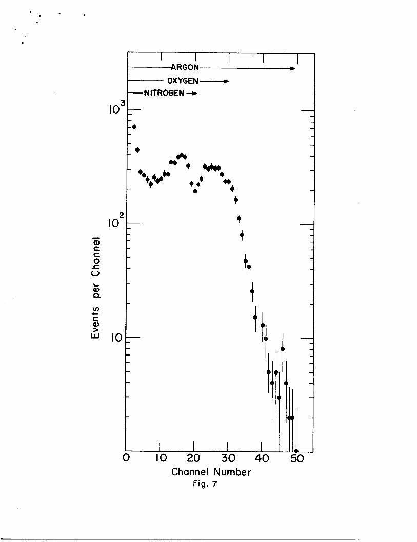
After the high-level sources are inserted into the instru-
ment, it can be checked in air. The response under these condi-
tions is illustrated in Fig. 7. The alpha mode, even in the poorly
defined geometry of a gaseous sample, clearly identifies the
nitrogen and oxygen in the air. The level of response, as well
as some qualitative features of the spectra, depends on the pres-
sure of air in the instrument. There are negligible events in
the proton mode when the instrument is operated at one atmosphere
of air, because of the unfavorable geometry for the N(a,p) pro-
ducts getting into the proton detectors.
Because of the short range of 6.11 alpha particles, quan-
titative results on samples must be obtained in vacuum. This, Gf
course, will be no problem on the lunar surface. In the present
studies, +,he head was kept in a vacuum chamber (P e ll~- Hg)> with
.
-16-
samples and test sources being presented through a vacuum lock.
After insertion of the sample, the head could be lowered to get
a reproducible - or known - distance between the source and detectors and the sample.
Figure 8 illustrates the response of the instrument to
the set of monochromatic alpha particles present in a source of
Th228 in equilibrium with its daughters.
pared in an isotope separator, with an accelerating potential of
40 KeV.
ment in the alpha mode is less than 1.8 per cent (full width at
half maximum) in the region 5 - 7 MeV.
This source was pre-
Figure 8 shows that the over-all resolution of the instru-
Using data of the type of Fig. 8, the energy scale of the instrument can be established. For the first prototype instru-
ment, on a reference date, the relation between channel number,
N, and energy, E (in MeV), was established to be (for the alpha
mode) :
N = 16.16 E - 4.31 . For the proton mode, less direct evidence (because of the gold
foil over the absorbers) gave:
N = 18.0 E - 11.4 . Precision electronic pulser calibration of a second proto-
type has shown that the pulse-height analyzers of the type used
in these instruments is linear to better than a few per cent down
to about channel 10.

. .
-17-
Figures 9 and. 10 show the response of the instrument to
several pure elernents in the alpha and proton modes, respectively.
The d.ata are from several combined. runs, with the information normalized. to a source strength of 6.7 x 10 10 d./m, and. a measure-
ment time of 1000 min. The data has been corrected. for small
electronic shifts of the instrument, and. the background has a1read.y
been subtracted. The d.ata of Figs. 9 and. 10 are similar to those obtained in the report of Patterson, Turkevich, and Franzgrote. 2
Together with the response from other elements, these represent a
"library" on the basis of which the response from a complex sub-
stance can be used. to d.etermine the chemical composition of the
substance.
V. ACKNOWLEDGMENTS
The d.evelopment and. construction of this instrument has
involved the collaboration of the staff of the Laboratory for
Astrophysics and Space Research under the general supervision of
James E. Lamport. Robert Takaki was responsible for designing
many of the electronic circuits, Myron Weber and Ed. Blume for
much of the mechanical d.esign, and. Anthony J. Tuzzolino and Murray
Perkins for the fabrication of many special detectors needed in
this work. At the Argonne National Laboratory, Jerome Lerner
prepared. the Th 228 source and. Dale Hend.erson performed. many mea-
surements on the Cm 242 sources used. in this work.
Propulsion Laboratory, Glenn Sisk and. Timothy Harrington contri-
buted., particularly to the adaptation of the instrument to
Surveyor requirements.
At the Jet
-18-
This instrument was d.eveloped. and. tested. und.er partial
support from the National Aeronautics and. Space Administration
at the University of Chicago (under grant NsG-127-61 and. sub-
contracts JPL-NASA 950750 and. 950315 with the Jet Propulsion
Laboratory). The work at the Argonne National Laboratory was
supported. by the United. States Atomic Energy Commission; that
at the Jet Propulsion Laboratory by contract NAS 7-100 of the
National Aeronautics and. Space Administration.

-19 -
REFERENCES * Work at the University of Chicago supported. in part by
the National Aeronautics and. Space Ad,ministration under grant
NsG-127-61 and. subcontracts JPL-NASA 950750 and. 950315 with the
Jet Propulsion Laboratory, at the Argonne National Laboratory
by the United. States Atomic Energy Commission, and. at the Jet
Propulsion Laboratory by contract NAS 7-100 of the National
Aeronautics and Space Administration.
' Present ad.d.ress: Tulpenhofstrasse 29, Offenbach Am Main,
Germany.
* Present ad.d.ress: University of Michigan, Box 618 Ann Arbor, Michigan.
A. Turkevich, Science - 134, 672 (1961).
* J. H. Patterson, A. Turkevich, and. E. Franzgrote, J. Geophys. Res. - 70, 1311 (1965).
3 E. P. HOrWitZ, C. A. Bloomquist, H. w. Harvey, D. Cohen, and L= J. Basile, "The Purification of 10 Curies of Cm242,11 AN~-6gg8
(1965)
N. A. Eskind. and. H. Mark, J. Geophys. Res. 67, 4867 (1962).
5 A. J. Tuzzolino, J. Kristoff, and. M. A. Perkins, Nucl. Instr.
4 -
Meth. - 36, 73 (1965); Nucl. Instr. Meth. - 37, 204 (1965).
See e.g., C . Y. Fan, G. Gloeckler, and. J. Simpson, J. Geophys. 6
Res= - 7OJ 3515 (1965); S . M. Comstock, C. Y. Fan, and. J. Simpson,
Ast.rophys. J. (1966) (to be published.).
A. Turkevich, K. Knolle, E. Franzgrote, and. J. H. Patterson (in preparation) .

FIG. 1
Alpha-Scattering Instrument for Surface Analysis. The
two units of the instrument are the boxes on the table on the
right side of the figure. The d.eployable head. is the unit on
the right.
handling simulators and. test and. monitor equipment.
The electronic racks inc1ud.e spacecraft d.ata

Y
i
I
I d
Fig. I

.
FIG. 2
Alpha-Scattering Instrument: View up through bottom
opening of Head. U n i t . The s i x col l imated alpha sources, t h e
two alpha d.etectors, and. t h e four proton d.etectors a r e id.en-
t i f i e d . . The alpha sources and. de t ec to r s a r e - 5.7 em up from
t h e opening; t h e proton de tec to r s a r e about 5 em away ( s e e
Fig. 3 ) .

Six Collimated Alpha Sources
c
Two Alpha Detectors r
L F o u r Proton Detectors
I
i
!
Fq. 2

Alpha-Scattering Instrument: Some geometrical relationships
between parts of the head unit. The top part of the figure shows
a horizontal cross section about 2/3 of the way up the head unit.
The bottom part of the figure shows a vertical cross section
approximately through the center of the unit. The six source
hold.ers (s), the two alpha d.etectors (a), and. the four proton
detectors (p) are shown, together with typical paths for the
alpha particles and protons.

,
A t
r
\
/ \ P \
I I
\\
\ I I
\ \ /
P E’’ \ 1 ‘
+ f
0 5
Alpha Detector ( I of 21, Source Holder ( I of 6 )
Detector 4 )
Section A- A
Fig. 3

F I G . 4
Alpha-Scattering Instrument. Details of construction of
Alpha Source Hold.ers, Alpha Detectors, and Proton Detectors.

'
Detector Plug Detector Spring Detector Spacer
Retainer Screw
Alpha Source
Source Holder
Collimator A1203Film
SOURCE ASSEMBLY
Detector Mount
ALPHA DETECTOR ASSEMBLY
0 1 2 Cm
Mask
Gold Foil PROTON DETECTOR
Fig. 4

.
FIG. 5
Alpha-Scattering Instrument. Block Diagram of E lec t ron ic s
i n Head. Unit .
Legend. :
(2-1, a-2:
P-1, ... P-4:
G-1 , G - 4 :
B:
S :
PRE :
M:
P.A.1
L.G. :
D.L. :
DISC. :
T.G. :
H.T.C. :
E:
D:
Two s i l i c o n semiconductor d.etectors arranged. t o d.etect a lpha p a r t i c l e s .
Four s i l i c o n semiconductor de t ec to r s arranged. t o d.etect protons.
Four guard. d.etectors i n anticoincid.ence with t h e proton d.etectors to lower t h e background. i n t h e proton d.etectors .
Appropriate b i a s vo l tages f o r t h e s i l i c o n d.etectors.
E lec t ronic switches, actuated. by ground. command., t h a t can block outputs of separa te a lpha d e t e c t o r s o r s epa ra t e proton-guard d.etector combinations.
Preampl i f ie rs .
Mixing c i r c u i t s f o r combining outputs o f de t ec to r combinations.
Pos tampl i f ie rs .
Linear Gates.
Delay Line.
Discriminator.
Threshold. Gates.
Height-to-Time Convertors.
Output o f H.T.C. goes v i a cable t o Elec t ronics Unit on Spacecraf t .
Signal from E lec t ron ic s Unit to block processing of Events i f D i g i t a l Elec- t r o n i c s a r e a1read.y processing an Event.

W * I I
I I I I I I
1

. b
FIG. 6
Alpha-Scattering Instrument. Block Diagram of Electronics
in Electronics Unit.
Legend. :
E: Analogue signal from Head. Unit.
D: Signal to Head. Unit to block processing of new pulses when buffer counters are filled..
DLC: Delay Line Clock.
C : Seven-bit Counter.
BS: Two buffer storage counters for time smoothing of d.ata.
PSC: Parallel to serial converter.
PG: Parity Generator.
G: Signal f o r synchronization of d.ata output with spacecraft clock.
F: Data output to spacecraft (s/c).
P: Power supply converting 29 volt spacecraft voltage to lOOV, 29V, and. 7-volt levels need.ed. in instrument electronics.
M: Electronic memory for processing commands to turn outputs of ind.ivid.ua1 d.etectors on and. off.

E = DLC - C
Command Pulses
* PSC
E C 1 1 1 1 1 1 1
I
PG - F
wllll D-
I 7v 29V ~
I B S I
2 9 V S/C P
PCS PG b F
Alpha Mode I
PCS PG
Proton Mode
c
b F
Fig.6

. I A
a
FIG. 7
Spectrum Obtained. in Alpha M0d.e of Alpha-Scattering
Instrument, P-1, with air in the instrument. The ord.inates
are events per channel in a 75 min. measurement with a total
source strength of 7 x 10 d/m; the abscissae are channel
numbers of the pulse-height analyzer of the instrument. The
10
relation between channel number and. energy is ind.icated in
the text. The energy (channel) regions in which the prin-
cipal constituents of air contribute are indicated at the top.
t C
8
- a c C 0
-E= 0
a Q
v)
c a
L
t
5
10:
IO2
IO
i I I I I N R G O N m
OXYGEN - -NITROGEN +
b
+ i t
4 t
Channel Number Fig. 7

FIG. 8
Response of Alpha-Scattering Instrument, P-1 (Alpha Mode)
to Th 228 (in equilibrium with its d.aughters) . The literature
values of the energy of the Alpha-Particle Groups are indicated
at the top of the figure. The highest energy alpha group in
this series (8.78 MeV) has t oo high an energy for the pulse-
height analyzer of the instrument and. appears in the overflow
channel (126).

t” 4 .
L
4
t .- v) c Q)
c t -
I80
160
Nominal Energies (MeV) 5.42 5.68 6.056.28 6.78
I
140,-
120
IO0
80
60 i 70 80
Channel Number Fig. 8

t t
. c
FIG. 9
Response of the Alpha-Scattering Instrument in the Alpha
Mode to Three Pure Elements.
nesium, and. iron. The ordinates are events per channel
registered in 1000 min., as a function of channel number. The
source strength was 6.7 x lolo d./m.
The d.ata are for carbon, mag-

t - . c
d
E 3
lLJ 000 I /3

FIG. 10
Response of the Alpha-Scattering Instrument in Proton
M0d.e to Three Pure Elements. The data are for aluminum,
silicon, and. phosphorous. The ord.inates are events per
channel registered in 1000 min., as a function of channel
number. The source strength was 6.7 x lo1' d./m.

I /
0 Q
0 m
0 00
0 d-


![Karlfried Graf Dukheim - Meditar, Porque y Como[1]](https://img.pdfslide.us/doc/110x75/577c82581a28abe054b05f15/karlfried-graf-dukheim-meditar-porque-y-como1.jpg)


