Embed Size (px)
Citation preview
i
Motherboard User’s Guide
This publication, including photographs, illustrations and software, is under theprotection of international copyright laws, with all rights reserved. Neither thisuser’s guide, nor any of the material contained herein, may be reproducedwithout the express written consent of the manufacturer.The information in this document is subject to change without notice. Themanufacturer makes no representations or warranties with respect to thecontents hereof and specifically disclaims any implied warranties of merchant-ability or fitness for any particular purpose. Further, the manufacturer reservesthe right to revise this publication and to make changes from time to time in thecontent hereof without obligation of the manufacturer to notify any person ofsuch revision or changes.
TrademarksIBM, VGA, and PS/2 are registered trademarks of International BusinessMachines.Intel, Pentium/II/III, Pentium 4, Celeron and MMX are registered trademarks ofIntel Corporation.Microsoft, MS-DOS and Windows 2000/XP/Vista are registered trademarks ofMicrosoft Corporation.AMI is a trademark of American Megatrends Inc.It has been acknowledged that other brands or product names in this manual aretrademarks or the properties of their respective owners.
Static Electricity Precautions1. Don’t take this motherboard and components out of their original static-
proof package until you are ready to install them.2. While installing, please wear a grounded wrist strap if possible. If you
don’t have a wrist strap, discharge static electricity by touching the baremetal of the system chassis.
3. Carefully hold this motherboard by its edges. Do not touch thosecomponents unless it is absolutely necessary. Put this motherboard onthe top of static-protection package with component side facing upwhile installing.
Pre-Installation Inspection1. Inspect this motherboard whether there are any damages to components
and connectors on the board.2. If you suspect this motherboard has been damaged, do not connect
power to the system. Contact your motherboard vendor about thosedamages.
Copyright © 2007All Rights Reserved
P55G Series, V1.0October 2007
ii
Motherboard User’s Guide
Exit Without Saving ...................................................................................................... 33
Trademark ............................................................................................................ iStatic Electricity Precautions ......................................................................................... iPre-Installation Inspection ............................................................................................. i
Chapter 1: Introduction ..................................................................................... 1Key Features .................................................................................................................... 1Package Contents ........................................................................................................... 4
Chapter 2: Motherboard Installation .............................................................. 5Motherboard Components ............................................................................................ 6I/O Ports .......................................................................................................................... 7Installing the Processor ................................................................................................. 8Installing Memory Modules .......................................................................................... 9Jumper Settings ............................................................................................................ 12Install the Motherboard ............................................................................................... 14Connecting Optional Devices ..................................................................................... 15Install Other Devices .................................................................................................... 17Expansion Slots ............................................................................................................. 19
Chapter 3: BIOS Setup Utility ....................................................................... 21Introduction .................................................................................................................. 21Running the Setup Utility ........................................................................................ ...21Standard CMOS Setup Page ....................................................................................... 22Advanced Setup Page .................................................................................................. 24Advanced Chipset Setup Page .................................................................................... 26Integrated Peripherals Page ....................................................................................... 27Power Management Setup Page ................................................................................. 28PCI/PnP Setup Page .................................................................................................... 29PCI Health Status Page ............................................................................................... 30Frequency/Voltage Control Page ............................................................................... 31Load Default Settings ................................................................................................... 32Supervisor Password Page .......................................................................................... 32User Password Page ..................................................................................................... 33Save & Exit Setup ......................................................................................................... 33
Chapter 4: Software & Applications .............................................................. 34Introduction .................................................................................................................. 34Installing Support Software ........................................................................................ 34Bundled Software Installation .................................................................................... 38
Table of Contents
iii
Motherboard User’s Guide
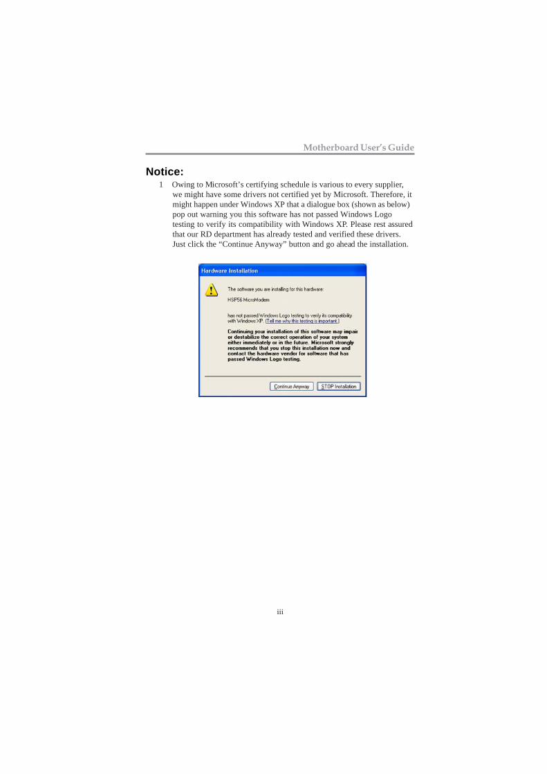
Notice:1 Owing to Microsoft’s certifying schedule is various to every supplier,
we might have some drivers not certified yet by Microsoft. Therefore, itmight happen under Windows XP that a dialogue box (shown as below)pop out warning you this software has not passed Windows Logotesting to verify its compatibility with Windows XP. Please rest assuredthat our RD department has already tested and verified these drivers.Just click the “Continue Anyway” button and go ahead the installation.
1
Chapter 1: Introduction
Chapter 1 Introduction
Note: Hyper-Threading technology enables the operating system intothinking it’s hooked up to two processors, allowing two threads to berun in parallel, both on separate ‘logical’ processors within the samephysical processor.
LGA775 Socket Processor• Supports the latest Intel® CoreTM 2 Quad*/CoreTM 2 Duo/Pentium®
D*/Pentium® 4*/Celeron® D processors with Hyper-ThreadingTechnology
• Supports over spec up to 1333* MHz Front-Side Bus
Key FeaturesThe key features of this motherboard include:
It is a Micro ATX motherboard and has power connectors for an ATX powersupply.
This motherboard integrates a single-chip NVIDIA® MCP73V that supports theSerial ATA interface for high-performance and mainstream desktop PCs; thebuilt-in USB 2.0 providing higher bandwidth, implementing USB 2.0 EHCI andUSB 1.1 OHCI. It supports High Definition Audio Codec and provides UltraDMA 133/100/66/33 function. It has one PCI Expressx16, one PCI Expressx1and two 32-bit PCI slots. There is a full set of I/O ports including two PS/2ports for mouse and keyboard, οne serial port, one VGA port, one LAN port,four back-panel USB 2.0 ports and Audio jacks for microphone, line-in and line-out and onboard USB headers providing extra ports by connecting the ExtendedUSB Module to the motherboard.
This motherboard has a LGA775 socket for latest Intel® CoreTM 2 Quad*/Core
TM 2 Duo/Pentium® D*/Pentium® 4*/Celeron® D processors with
Hyper-Threading Technology and Front-Side Bus (FSB) speeds up to 1066/800 MHz (Over spec up to 1333*). Hyper-Threading Technology, designed totake advantage of the multitasking features, giving you the power to do morethings at once.
“ * ” stands for this motherboard is ready to support Intel® CoreTM 2 Quad/Pentium® D/Pentium® 4 processor and over spec to support FSB1333and DDR2 800. Please refer to memory QVL and CPU support list onPCCHIPS website.
2
Motherboard User’s Guide
Serial ATA• Serial ATA Connector• Transfer rate exceeding best ATA (3.0 Gb/s) with scalability to higher
rates• Low pin count for both host and devices
Onboard IDE channels• One IDE Connector• Supports PIO (Programmable Input/Output) and DMA (Direct Memory
Access) modes• Supports IDE Ultra DMA bus mastering with transfer rates of 133/100/
66/33 MB/sec
Expansion Slots• Two 32-bit PCI slots• One PCI Express x16 slot• One PCI Express x1 slot
Memory Support• Two 240-pin DIMM sockets for DDR2 SDRAM memory modules• Supports DDR2 667/533 (Over spec up to 800*) memory bus• Maximum installed memory is 4 GB
• System Memory Controller Support: DDR2 SDRAM with up tomaximum memory of 4 GB.
• PCI Express Graphics Interface Support: One PCI Express x16 port• PCI Bus Interface Support: PCI Revision 2.3 Specification at 33MHz• Integrade Serial ATA Host Controller with Data transfer rates up to 3.0
Gb/s• Intgrated IDE Controller: Ultra DMA-133/100/66/33 Bus Master EIDE
Controller• USB 2.0: Integrated USB 2.0 interface, supporting up to eight functional
ports
• Hyper-Threading Technology
• High Performance Host Interface: Supports Intel® CoreTM 2 Quad*/Core
TM 2 Duo/Pentium® D*/Pentium® 4*/Celeron® D processor
family with over spec up to FSB1333* MHz
Chipset
The NVIDIA® MCP73V is a single-chip with proven reliability and performance.
3
Chapter 1: Introduction
LAN
Onboard I/O Ports• Two PS/2 ports for mouse and keyboard• One serial port• One VGA port• One LAN port• Four back-panel USB2.0 ports• Audio jacks for microphone, line-in and line-out
Audio
• 10/100 Mb/s dual speed transceiver• MII interface for external MAC devices• 10/100 Mb/s IEEE 802.3 compliant• IEEE 802.3 Auto-Negotiation
• 6 Channels of DAC support 16/20/24-bit PCM Format for 5.1 Audio
• All ADCs support 48k/192k Independent Sample Rate• Exceeds Microsoft PC2001 Requirement• High Quality Differential CD input• Power Support: Digital: 3.3V; Analog: 3.3V/5.0V
BIOS FirmwareThis motherboard uses Award BIOS that enables users to configure many systemfeatures including the following:
• Power management• Wake-up alarms• CPU parameters and memory timing• CPU and memory timing
The firmware can also be used to set parameters for different processor clockspeeds.
Note: Hardware specifications and software items are subject to changewithout notification.
Dimensions• Micro ATX form factor of 244 x 194 mm
Solution
4
Motherboard User’s Guide
Package ContentsYour motherboard package ships with the following items:
The motherboardThe User’s GuideOne diskette drive ribbon cable (optional)One IDE drive ribbon cableThe Software support CD
Optional AccessoriesYou can purchase the following optional accessories for thismotherboard.
The Extended USB moduleThe CNR v.90 56K Fax/Modem cardThe Serial ATA cableThe Serial ATA power cable
Note: You can purchase your own optional accessories from the third party,but please contact your local vendor on any issues of the specificationand compatibility.
5
Chapter 2: Motherboard Installation
Chapter 2 Motherboard InstallationTo install this motherboard in a system, please follow these instructions in thischapter:
Identify the motherboard componentsInstall a CPUInstall one or more system memory modulesMake sure all jumpers and switches are set correctlyInstall this motherboard in a system chassis (case)Connect any extension brackets or cables to headers/connectors on themotherboardInstall peripheral devices and make the appropriate connections toheaders/connectors on the motherboard
Note:1. Before installing this motherboard, make sure jumper CLR_CMOS is
under Normal setting. See this chapter for information about locatingCLR_CMOS and the setting options.
2. Never connect power to the system during installation; otherwise, itmay damage the motherboard.
6
Motherboard User’s Guide
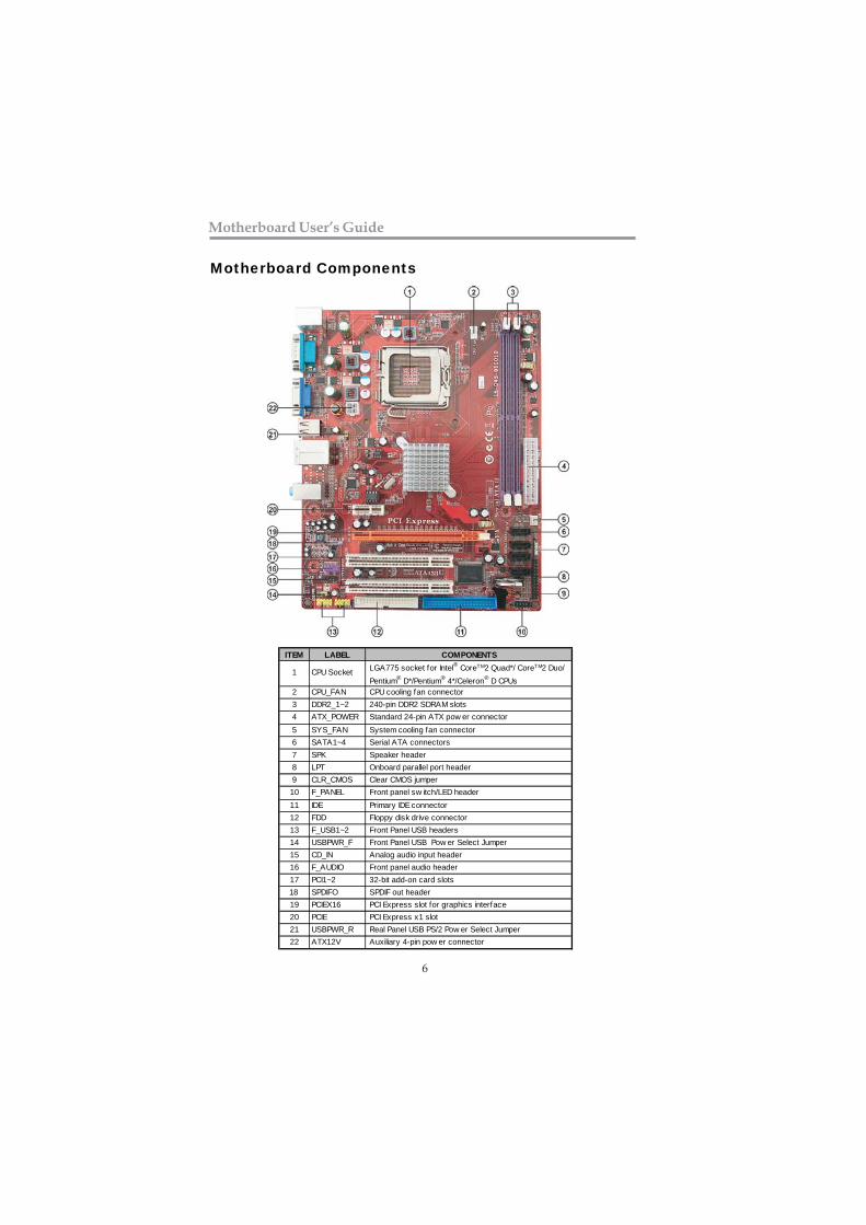
Motherboard Components
ITEM LABEL COMPONENTS LGA775 socket for Intel® CoreTM2 Quad*/ CoreTM2 Duo/ Pentium® D*/Pentium® 4*/Celeron® D CPUs
2 CPU_FAN CPU cooling fan connector3 DDR2_1~2 240-pin DDR2 SDRAM slots4 ATX_POWER Standard 24-pin ATX pow er connector5 SYS_FAN System cooling fan connector6 SATA1~4 Serial ATA connectors7 SPK Speaker header8 LPT Onboard parallel port header9 CLR_CMOS Clear CMOS jumper
10 F_PANEL Front panel sw itch/LED header11 IDE Primary IDE connector12 FDD Floppy disk drive connector13 F_USB1~2 Front Panel USB headers14 USBPWR_F Front Panel USB Pow er Select Jumper15 CD_IN Analog audio input header16 F_AUDIO Front panel audio header17 PCI1~2 32-bit add-on card slots18 SPDIFO SPDIF out header19 PCIEX16 PCI Express slot for graphics interface20 PCIE PCI Express x1 slot21 USBPWR_R Real Panel USB PS/2 Pow er Select Jumper22 ATX12V Auxiliary 4-pin pow er connector
1 CPU Socket
7
Chapter 2: Motherboard Installation
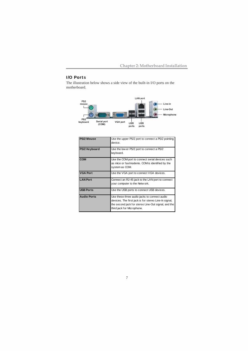
I/O PortsThe illustration below shows a side view of the built-in I/O ports on themotherboard.
PS/2 Mouse Use the upper PS/2 port to connect a PS/2 pointingdevice.
PS/2 Keyboard Use the low er PS/2 port to connect a PS/2keyboard.
COM Use the COM port to connect serial devices suchas mice or fax/modems. COM is identified by thesystem as COM.
VGA Port Use the VGA port to connect VGA devices.
LAN Port Connect an RJ-45 jack to the LAN port to connectyour computer to the Netw ork.
USB Ports Use the USB ports to connect USB devices.
Audio Ports Use these three audio jacks to connect audiodevices. The first jack is for stereo Line-In signal,the second jack for stereo Line-Out signal, and thethird jack for Microphone.
8
Motherboard User’s Guide
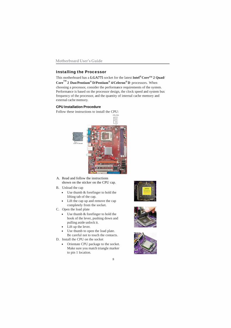
Installing the ProcessorThis motherboard has a LGA775 socket for the latest Intel® CoreTM 2 Quad/Core
TM 2 Duo/Pentium® D/Pentium® 4/Celeron® D processors. When
choosing a processor, consider the performance requirements of the system.Performance is based on the processor design, the clock speed and system busfrequency of the processor, and the quantity of internal cache memory andexternal cache memory.
CPU Installation ProcedureFollow these instructions to install the CPU:
B. Unload the cap• Use thumb & forefinger to hold the
lifting tab of the cap.• Lift the cap up and remove the cap
completely from the socket.C. Open the load plate
• Use thumb & forefinger to hold thehook of the lever, pushing down andpulling aside unlock it.
• Lift up the lever.• Use thumb to open the load plate.
Be careful not to touch the contacts.D. Install the CPU on the socket
• Orientate CPU package to the socket.Make sure you match triangle markerto pin 1 location.
A. Read and follow the instructions shown on the sticker on the CPU cap.
9
Chapter 2: Motherboard Installation
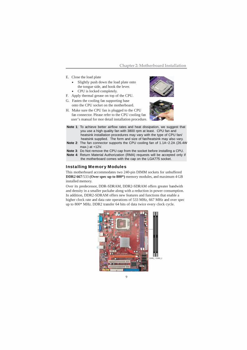
E. Close the load plate• Slightly push down the load plate onto
the tongue side, and hook the lever.• CPU is locked completely.
F. Apply thermal grease on top of the CPU.G. Fasten the cooling fan supporting base onto the CPU socket on the motherboard.H. Make sure the CPU fan is plugged to the CPU fan connector. Please refer to the CPU cooling fan user’s manual for mor detail installation procedure.
Installing Memory ModulesThis motherboard accommodates two 240-pin DIMM sockets for unbufferedDDR2 667/533 (Over spec up to 800*) memory modules, and maximum 4 GBinstalled memory.Over its predecessor, DDR-SDRAM, DDR2-SDRAM offers greater bandwithand density in a smaller packahe along with a reduction in power consumption.In addition, DDR2-SDRAM offers new features and functions that enable ahigher clock rate and data rate operations of 533 MHz, 667 MHz and over specup to 800* MHz. DDR2 transfer 64 bits of data twice every clock cycle.
Note 1: To achieve better airflow rates and heat dissipation, we suggest that you use a high quality fan with 3800 rpm at least. CPU fan and heatsink installation procedures may vary with the type of CPU fan/ heatsink supplied. The form and size of fan/heatsink may also vary.Note 2: The fan connector supports the CPU cooling fan of 1.1A~2.2A (26.4W max.) at +12V.Note 3: Do Not remove the CPU cap from the socket before installing a CPU.Note 4: Return Material Authorization (RMA) requests will be accepted only if the motherboard comes with the cap on the LGA775 socket.
10
Motherboard User’s Guide
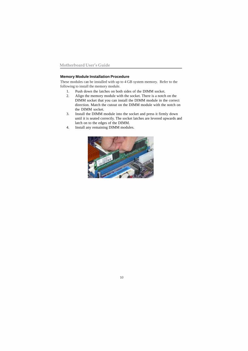
Memory Module Installation ProcedureThese modules can be installed with up to 4 GB system memory. Refer to thefollowing to install the memory module.
1. Push down the latches on both sides of the DIMM socket.2. Align the memory module with the socket. There is a notch on the
DIMM socket that you can install the DIMM module in the correctdirection. Match the cutout on the DIMM module with the notch onthe DIMM socket.
3. Install the DIMM module into the socket and press it firmly downuntil it is seated correctly. The socket latches are levered upwards andlatch on to the edges of the DIMM.
4. Install any remaining DIMM modules.
11
Chapter 2: Motherboard Installation
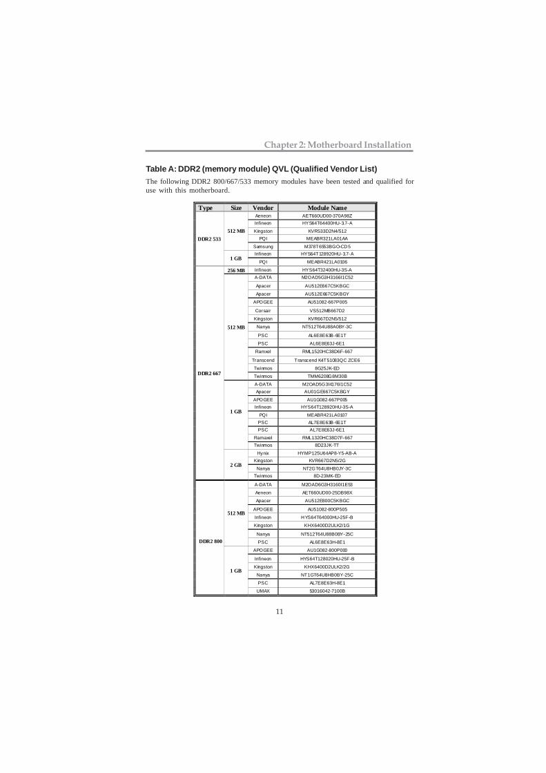
Table A: DDR2 (memory module) QVL (Qualified Vendor List)The following DDR2 800/667/533 memory modules have been tested and qualified foruse with this motherboard.
Type Size Vendor Module Name Aeneon AET660UD00-370A98Z Infineon HYS64T64400HU-3.7-A
Kingston KVR533D2N4/512 PQI MEABR321LA01AA
512 MB
Samsung M378T6553BGO-CD5 Infineon HYS64T128920HU-3.7-A
DDR2 533
1 GB PQI MEABR421LA0106
256 MB Infineon HYS64T32400HU-3S-A A-DATA M2OAD5G3H3166I1C52
Apacer AU512E667C5KBGC
Apacer AU512E667C5KBGY
APOGEE AU51082-667P005
Corsair VS512MB667D2
Kingston KVR667D2N5/512
Nanya NT512T64U88A0BY-3C
PSC AL6E8E63B-6E1T
PSC AL6E8E63J-6E1
Ramxel RML1520HC38D6F-667
Transcend Transcend K4T51083QC ZCE6
Twinmos 8G25JK-ED
512 MB
Twinmos TMM6208G8M30B
A-DATA M2OAD5G3I4176I1C52 Apacer AU01GE667C5KBGY
APOGEE AU1G082-667P005 Infineon HYS64T128920HU-3S-A
PQI MEABR421LA0107 PSC AL7E8E63B-6E1T PSC AL7E8E63J-6E1
Ramaxel RML1320HC38D7F-667
1 GB
Twinmos 8D23JK-TT
Hynix HYMP125U64AP8-Y5-AB-A Kingston KVR667D2N5/2G
Nanya NT2GT64U8HB0JY-3C
DDR2 667
2 GB
Twinmos 8D-23MK-ED
A-DATA M2OAD6G3H3160I1E53
Aeneon AET660UD00-25DB98X
Apacer AU512E800C5KBGC
APOGEE AU51082-800P505
Infineon HYS64T64000HU-25F-B
Kingston KHX6400D2ULK2/1G
Nanya NT512T64U88B0BY-25C
512 MB
PSC AL6E8E63H-8E1
APOGEE AU1G082-800P000
Infineon HYS64T128020HU-25F-B
Kingston KHX6400D2ULK2/2G
Nanya NT1GT64U8HB0BY-25C
PSC AL7E8E63H-8E1
DDR2 800
1 GB
UMAX 53016042-7100B
12
Motherboard User’s Guide
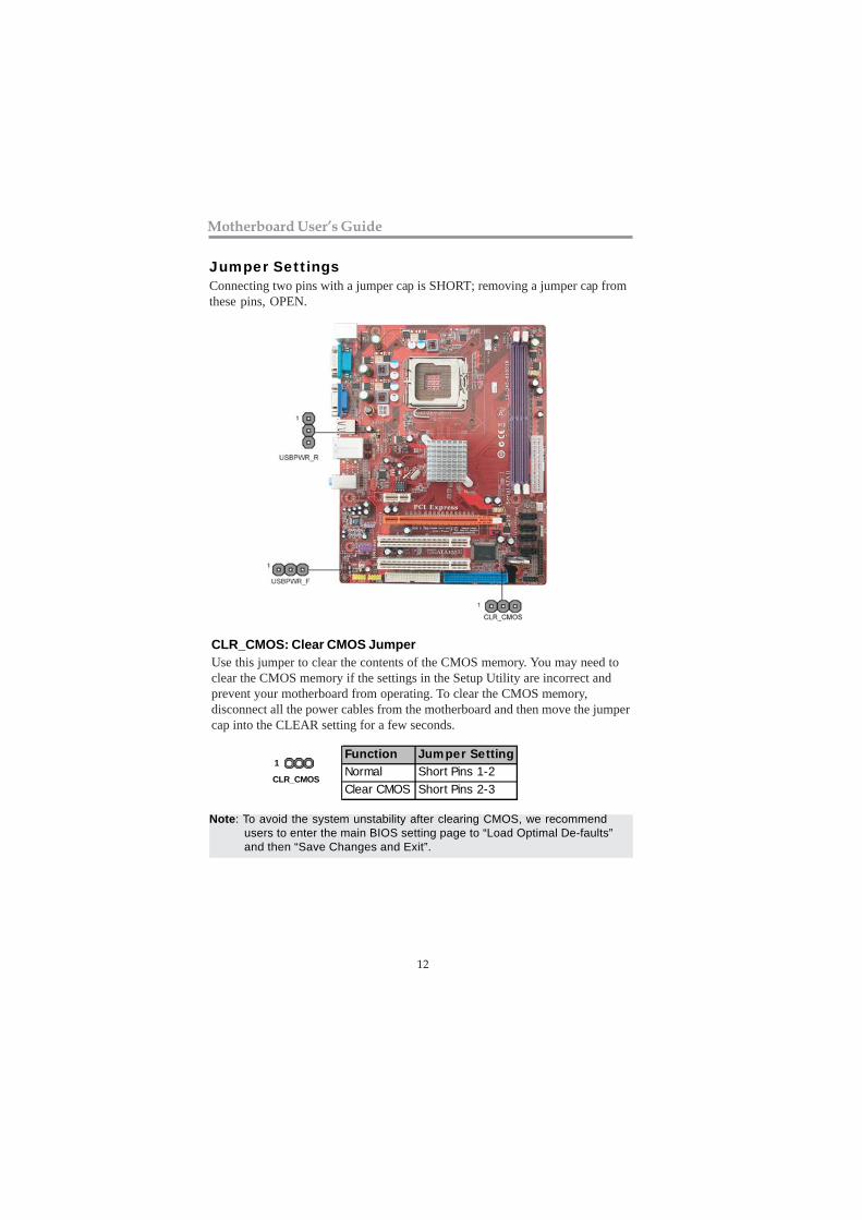
Jumper SettingsConnecting two pins with a jumper cap is SHORT; removing a jumper cap fromthese pins, OPEN.
CLR_CMOS: Clear CMOS JumperUse this jumper to clear the contents of the CMOS memory. You may need toclear the CMOS memory if the settings in the Setup Utility are incorrect andprevent your motherboard from operating. To clear the CMOS memory,disconnect all the power cables from the motherboard and then move the jumpercap into the CLEAR setting for a few seconds.
Function Jumper SettingNormal Short Pins 1-2Clear CMOS Short Pins 2-3
Note: To avoid the system unstability after clearing CMOS, we recommendusers to enter the main BIOS setting page to “Load Optimal De-faults”and then “Save Changes and Exit”.
CLR_CMOS
1
13
Chapter 2: Motherboard Installation
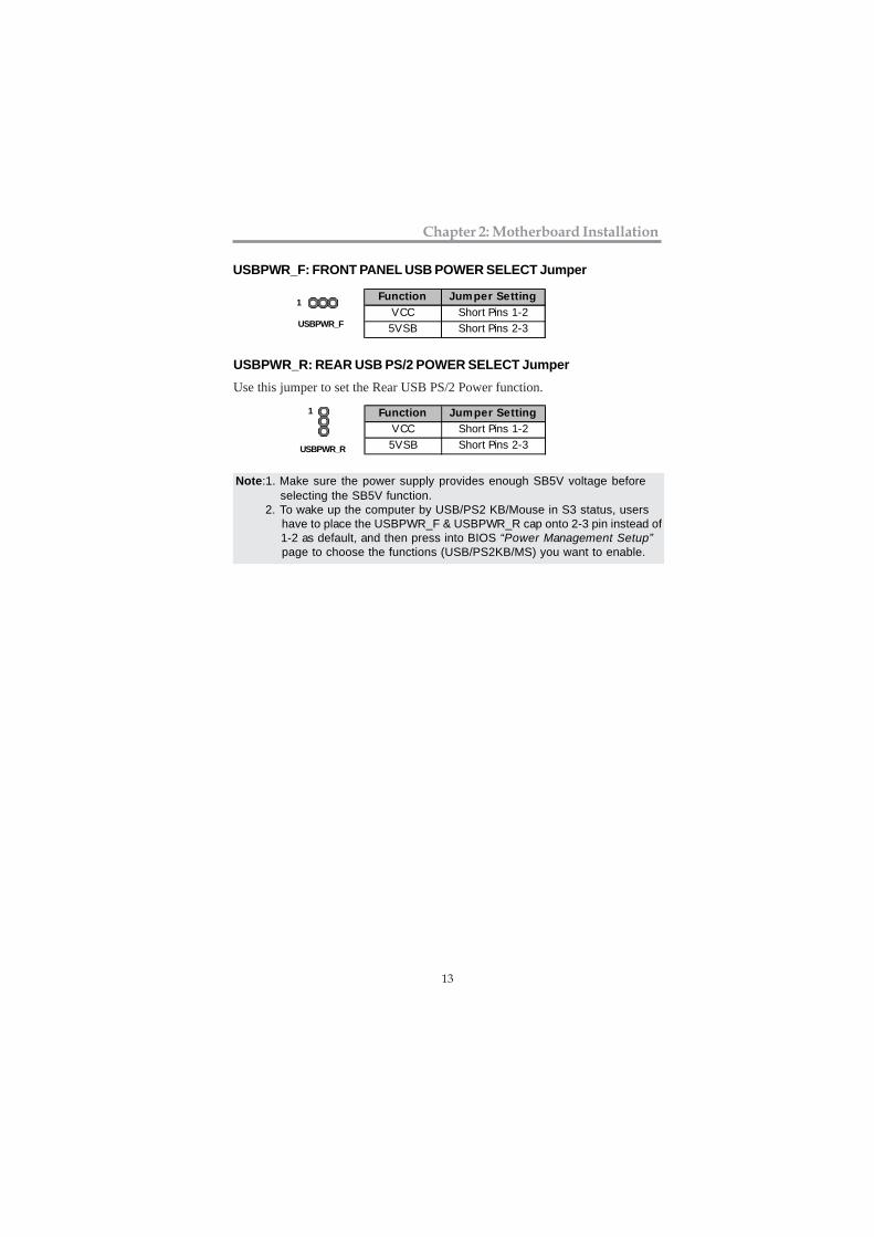
USBPWR_R: REAR USB PS/2 POWER SELECT JumperUse this jumper to set the Rear USB PS/2 Power function.
USBPWR_R
1 Function Jumper SettingVCC Short Pins 1-25VSB Short Pins 2-3
Note:1. Make sure the power supply provides enough SB5V voltage before selecting the SB5V function. 2. To wake up the computer by USB/PS2 KB/Mouse in S3 status, users have to place the USBPWR_F & USBPWR_R cap onto 2-3 pin instead of 1-2 as default, and then press into BIOS “Power Management Setup” page to choose the functions (USB/PS2KB/MS) you want to enable.
USBPWR_F: FRONT PANEL USB POWER SELECT Jumper
USBPWR_F
1 Function Jumper SettingVCC Short Pins 1-25VSB Short Pins 2-3
14
Motherboard User’s Guide
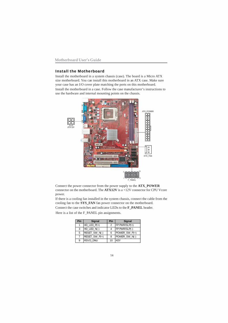
Pin Signal Pin Signal1 HD_LED_P(+) 2 FP PWR/SLP(+)3 HD_LED_N(-) 4 FP PWR/SLP(-)5 RESET_SW_N(-) 6 POWER_SW_P(+)7 RESET_SW_P(+) 8 POWER_SW_N(-)9 RSVD_DNU 10 KEY
Here is a list of the F_PANEL pin assignments.
Install the MotherboardInstall the motherboard in a system chassis (case). The board is a Micro ATXsize motherboard. You can install this motherboard in an ATX case. Make sureyour case has an I/O cover plate matching the ports on this motherboard.Install the motherboard in a case. Follow the case manufacturer’s instructions touse the hardware and internal mounting points on the chassis.
Connect the power connector from the power supply to the ATX_POWERconnector on the motherboard. The ATX12V is a +12V connector for CPU Vcorepower.If there is a cooling fan installed in the system chassis, connect the cable from thecooling fan to the SYS_FAN fan power connector on the motherboard.Connect the case switches and indicator LEDs to the F_PANEL header.
15
Chapter 2: Motherboard Installation
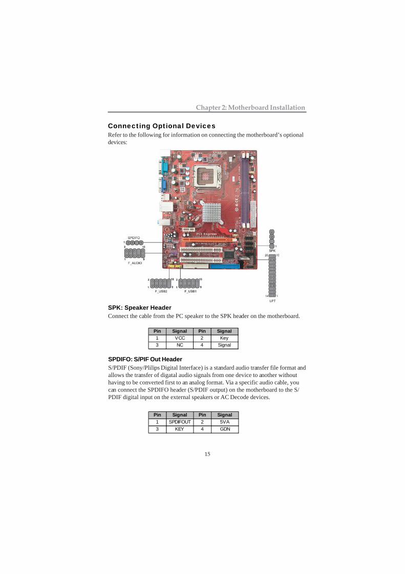
Pin Signal Pin Signal1 VCC 2 Key3 NC 4 Signal
Connecting Optional DevicesRefer to the following for information on connecting the motherboard’s optionaldevices:
SPK: Speaker HeaderConnect the cable from the PC speaker to the SPK header on the motherboard.
Pin Signal Pin Signal1 SPDIFOUT 2 5VA3 KEY 4 GDN
SPDIFO: S/PIF Out HeaderS/PDIF (Sony/Plilips Digital Interface) is a standard audio transfer file format andallows the transfer of digatal audio signals from one device to another withouthaving to be converted first to an analog format. Via a specific audio cable, youcan connect the SPDIFO header (S/PDIF output) on the motherboard to the S/PDIF digital input on the external speakers or AC Decode devices.
16
Motherboard User’s Guide
F_AUDIO: Front Panel Audio HeaderThis header allows the user to install auxiliary front-oriented microphone andline-out ports for easier access.
Pin Signal Pin Signal1 PORT1L 2 GND3 PORT1R 4 PRESENCE#5 PORT2R 6 Sense1_return7 SENSE_SEND 8 KEY9 PORT2L 10 Sense2_return
Pin Signal Pin Signal1 USBPWR0 2 USBPWR13 USB_FP_P0(-) 4 USB_FP_P1(-)5 USB_FP_P0(+) 6 USB_FP_P1(+)7 GROUND 8 GROUND9 KEY 10 NC
1. Locate the F_USB1~2 headers on the motherboard.2. Plug the bracket cable onto the F_USB1~2 headers.3. Remove a slot cover from one of the expansion slots on the system
chassis. Install an extension bracket in the opening. Secure theextension bracket to the chassis with a screw.
F_USB1~2: Front panel USB HeadersThe motherboard has four USB ports installed on the rear edge I/O port array.Additionally, some computer cases have USB ports at the front of the case. Ifyou have this kind of case, use auxiliary USB headers F_USB1~2 to connect thefront-mounted ports to the motherboard.
LPT: Onboard parallel port HeaderThis header allows the user to connect to the printer, scanner or devices.
Pin Signal Pin Signal1 STROBE 2 PD03 PD1 4 PD25 PD3 6 PD47 PD5 8 PD69 PD7 10 ACK
11 BUSK 12 PE13 SLCT 14 ALF15 ERROR 16 INIT17 SLCTIN 18 Ground19 Ground 20 Ground21 Ground 22 Ground23 Ground 24 Ground25 Ground 26 Key
17
Chapter 2: Motherboard Installation
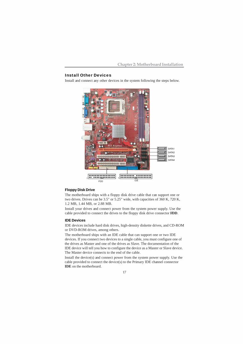
Install Other DevicesInstall and connect any other devices in the system following the steps below.
Floppy Disk DriveThe motherboard ships with a floppy disk drive cable that can support one ortwo drives. Drives can be 3.5" or 5.25" wide, with capacities of 360 K, 720 K,1.2 MB, 1.44 MB, or 2.88 MB.Install your drives and connect power from the system power supply. Use thecable provided to connect the drives to the floppy disk drive connector FDD.
IDE DevicesIDE devices include hard disk drives, high-density diskette drives, and CD-ROMor DVD-ROM drives, among others.The motherboard ships with an IDE cable that can support one or two IDEdevices. If you connect two devices to a single cable, you must configure one ofthe drives as Master and one of the drives as Slave. The documentation of theIDE device will tell you how to configure the device as a Master or Slave device.The Master device connects to the end of the cable.Install the device(s) and connect power from the system power supply. Use thecable provided to connect the device(s) to the Primary IDE channel connectorIDE on the motherboard.
18
Motherboard User’s Guide
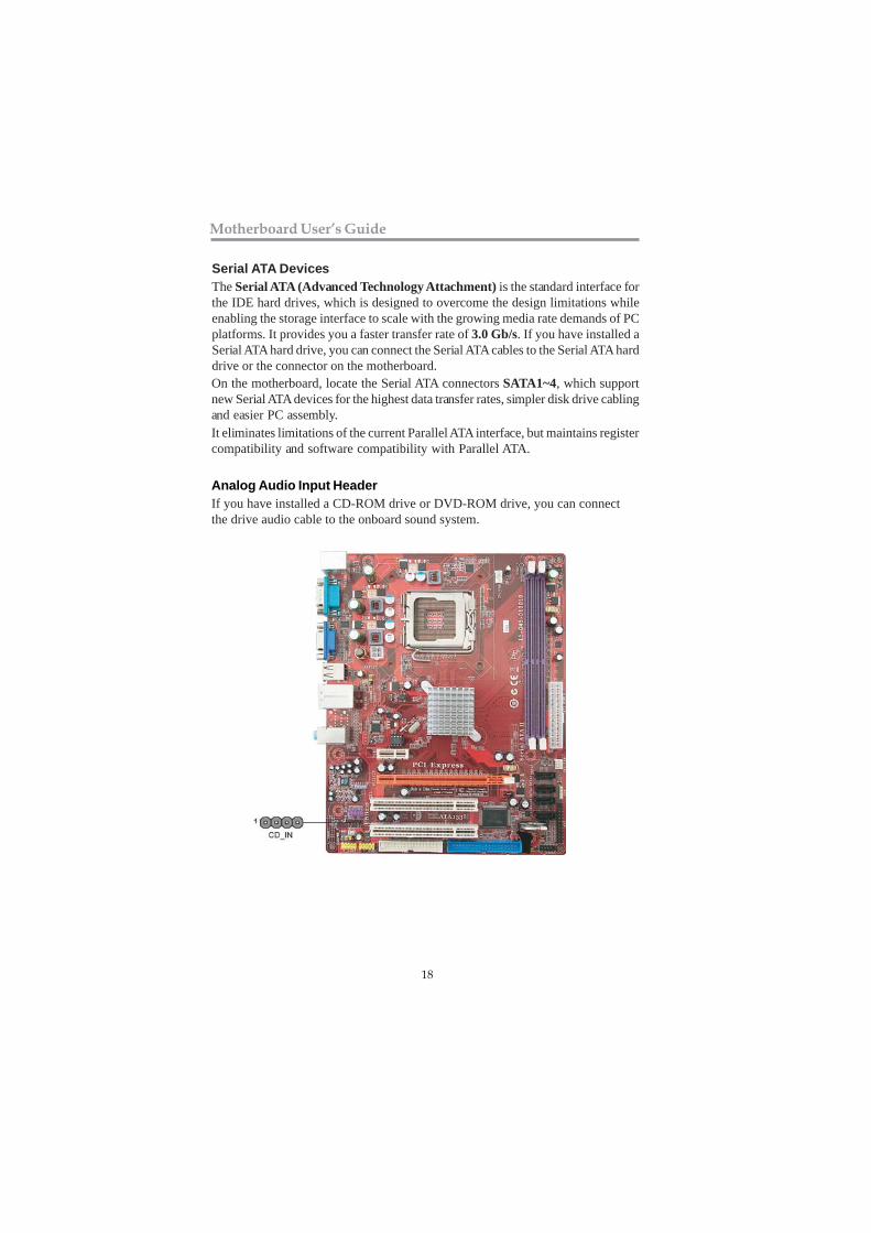
Serial ATA DevicesThe Serial ATA (Advanced Technology Attachment) is the standard interface forthe IDE hard drives, which is designed to overcome the design limitations whileenabling the storage interface to scale with the growing media rate demands of PCplatforms. It provides you a faster transfer rate of 3.0 Gb/s. If you have installed aSerial ATA hard drive, you can connect the Serial ATA cables to the Serial ATA harddrive or the connector on the motherboard.On the motherboard, locate the Serial ATA connectors SATA1~4, which supportnew Serial ATA devices for the highest data transfer rates, simpler disk drive cablingand easier PC assembly.It eliminates limitations of the current Parallel ATA interface, but maintains registercompatibility and software compatibility with Parallel ATA.
Analog Audio Input HeaderIf you have installed a CD-ROM drive or DVD-ROM drive, you can connectthe drive audio cable to the onboard sound system.
19
Chapter 2: Motherboard Installation
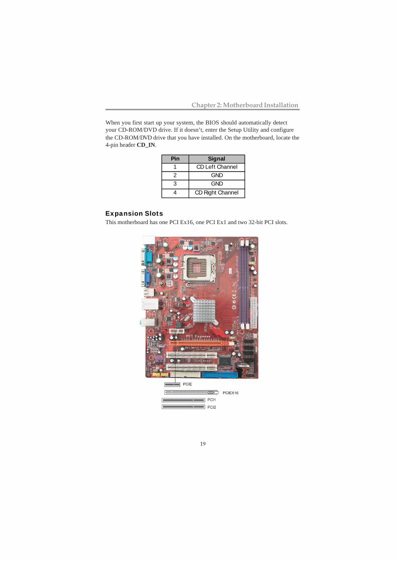
Expansion SlotsThis motherboard has one PCI Ex16, one PCI Ex1 and two 32-bit PCI slots.
the CD-ROM/DVD drive that you have installed. On the motherboard, locate the4-pin header CD_IN.
Pin Signal1 CD Left Channel2 GND3 GND4 CD Right Channel
When you first start up your system, the BIOS should automatically detectyour CD-ROM/DVD drive. If it doesn’t, enter the Setup Utility and configure
20
Motherboard User’s Guide
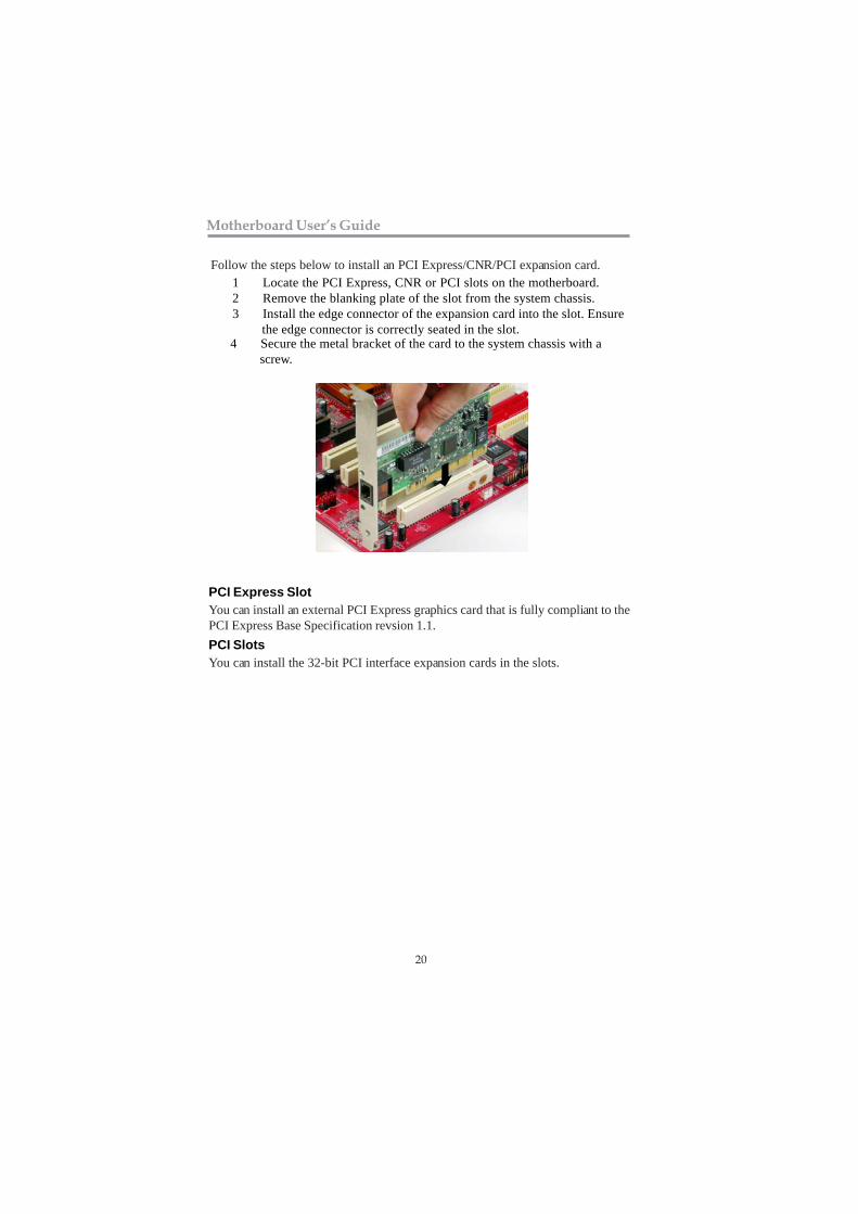
Follow the steps below to install an PCI Express/CNR/PCI expansion card.1 Locate the PCI Express, CNR or PCI slots on the motherboard.2 Remove the blanking plate of the slot from the system chassis.3 Install the edge connector of the expansion card into the slot. Ensure
the edge connector is correctly seated in the slot.4 Secure the metal bracket of the card to the system chassis with a
screw.
PCI Express SlotYou can install an external PCI Express graphics card that is fully compliant to thePCI Express Base Specification revsion 1.1.PCI SlotsYou can install the 32-bit PCI interface expansion cards in the slots.
21
Chapter 3: BIOS Setup Utility
Chapter 3 BIOS Setup Utility
IntroductionThe BIOS Setup Utility records settings and information of your computer, suchas date and time, the type of hardware installed, and various configurationsettings. Your computer applies the information to initialize all the componentswhen booting up and basic functions of coordination between system compo-nents.
If the Setup Utility configuration is incorrect, it may cause the system tomalfunction. It can even stop your computer booting properly. If it happens,you can use the clear CMOS jumper to clear the CMOS memory which hasstored the configuration information; or you can hold down the Page Up keywhile rebooting your computer. Holding down the Page Up key also clears thesetup information.
You can run the setup utility and manually change the configuration. You mightneed to do this to configure some hardware installed in or connected to themotherboard, such as the CPU, system memory, disk drives, etc.
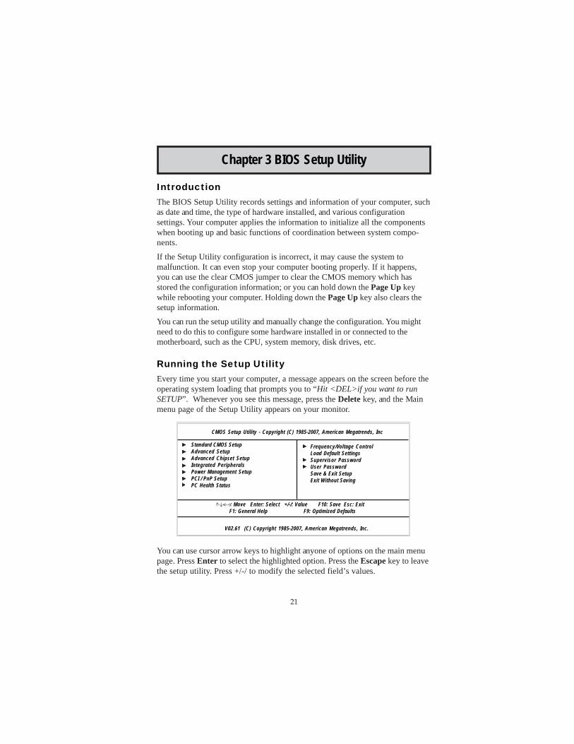
Running the Setup UtilityEvery time you start your computer, a message appears on the screen before theoperating system loading that prompts you to “Hit <DEL>if you want to runSETUP”. Whenever you see this message, press the Delete key, and the Mainmenu page of the Setup Utility appears on your monitor.
You can use cursor arrow keys to highlight anyone of options on the main menupage. Press Enter to select the highlighted option. Press the Escape key to leavethe setup utility. Press +/-/ to modify the selected field’s values.
V02.61 (C) Copyright 1985-2007, American Megatrends, Inc.
CMOS Setup Utility - Copyright (C) 1985-2007, American Megatrends, Inc
Standard CMOS SetupAdvanced SetupAdvanced Chipset SetupIntegrated PeripheralsPower Management SetupPCI / PnP SetupPC Health Status
Frequency/Voltage ControlLoad Default SettingsSupervisor PasswordUser PasswordSave & Exit SetupExit Without Saving
: Move Enter: Select +/-/: Value F10: Save Esc: Exit F1: General Help F9: Optimized Defaults
22
Motherboard User’s Guide
Some options on the main menu page lead to tables of items with installed valuesthat you can use cursor arrow keys to highlight one item, and press PgUp andPgDn keys to cycle through alternative values of that item. The other options onthe main menu page lead to dialog boxes requiring your answer OK or Cancel byselecting the [OK] or [Cancel] key.
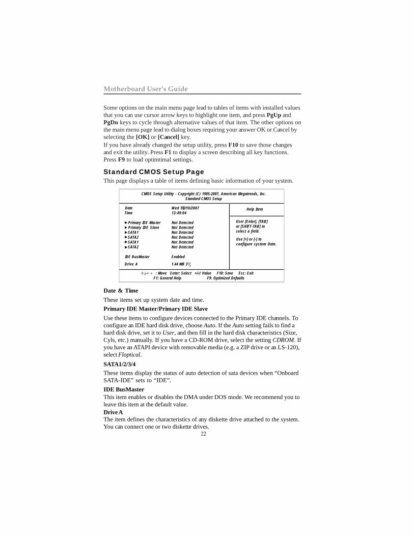
Standard CMOS Setup PageThis page displays a table of items defining basic information of your system.
Drive A
IDE BusMaster
These items set up system date and time.Primary IDE Master/Primary IDE SlaveUse these items to configure devices connected to the Primary IDE channels. Toconfigure an IDE hard disk drive, choose Auto. If the Auto setting fails to find ahard disk drive, set it to User, and then fill in the hard disk characteristics (Size,Cyls, etc.) manually. If you have a CD-ROM drive, select the setting CDROM. Ifyou have an ATAPI device with removable media (e.g. a ZIP drive or an LS-120),select Floptical.
If you have already changed the setup utility, press F10 to save those changesand exit the utility. Press F1 to display a screen describing all key functions.Press F9 to load optimtimal settings.
SATA1/2/3/4
Date & Time
The item defines the characteristics of any diskette drive attached to the system.You can connect one or two diskette drives.
This item enables or disables the DMA under DOS mode. We recommend you toleave this item at the default value.
These items display the status of auto detection of sata devices when “OnboardSATA-IDE” sets to “IDE”.
CMOS Setup Utility - Copyright (C) 1985-2007, American Megatrends, Inc.Standard CMOS Setup
Date Wed 10/10/2007 Time 13:49:04
Primary IDE Master Not DetectedPrimary IDE Slave Not Detected
SATA1 Not Detected SATA2 Not Detected SATA1 Not Detected SATA2 Not Detected
IDE BusMaster Enabled
Help Item
: Move Enter: Select +/-/: Value F10: Save Esc: Exit F1: General Help F9: Optimized Defaults
Drive A 1.44 MB 31/2
User [Enter], [TAB]or [SHIFT-TAB] toselect a field.
Use [+] or [-] toconfigure system Date.
23
Chapter 3: BIOS Setup Utility
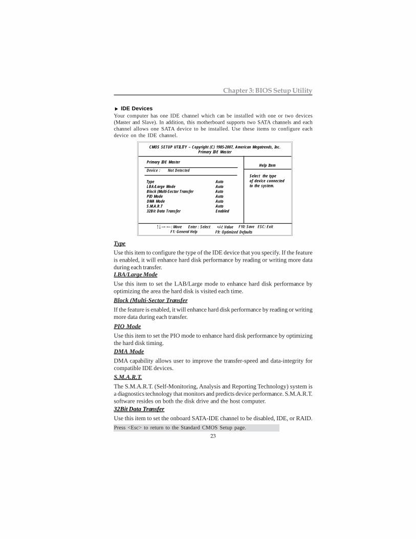
IDE DevicesYour computer has one IDE channel which can be installed with one or two devices(Master and Slave). In addition, this motherboard supports two SATA channels and eachchannel allows one SATA device to be installed. Use these items to configure eachdevice on the IDE channel.
Select the typeof device connectedto the system.
LBA/Large ModeUse this item to set the LAB/Large mode to enhance hard disk performance byoptimizing the area the hard disk is visited each time.Block (Multi-Sector TransferIf the feature is enabled, it will enhance hard disk performance by reading or writingmore data during each transfer.
TypeUse this item to configure the type of the IDE device that you specify. If the featureis enabled, it will enhance hard disk performance by reading or writing more dataduring each transfer.
CMOS SETUP UTILITY – Copyright (C) 1985-2007, American Megatrends, Inc.Primary IDE Master
Primary IDE Master
Type AutoLBA/Large Mode AutoBlock (Multi-Sector Transfer Auto
PIO Mode Auto DMA Mode Auto S.M.A.R.T Auto
32Bit Data Transfer Enabled
Help Item Device : Not Detected
F10: Save ESC: Exit: Move Enter : Select +/-/: ValueF9: Optimized DefaultsF1: General Help
32Bit Data TransferUse this item to set the onboard SATA-IDE channel to be disabled, IDE, or RAID.
S.M.A.R.T.The S.M.A.R.T. (Self-Monitoring, Analysis and Reporting Technology) system isa diagnostics technology that monitors and predicts device performance. S.M.A.R.T.software resides on both the disk drive and the host computer.
DMA ModeDMA capability allows user to improve the transfer-speed and data-integrity forcompatible IDE devices.
PIO ModeUse this item to set the PIO mode to enhance hard disk performance by optimizingthe hard disk timing.
Press <Esc> to return to the Standard CMOS Setup page.
24
Motherboard User’s Guide
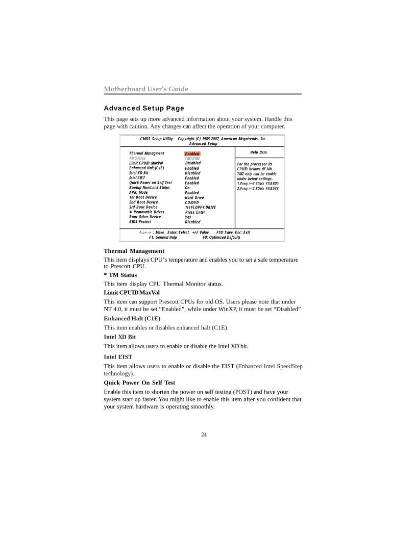
Advanced Setup PageThis page sets up more advanced information about your system. Handle thispage with caution. Any changes can affect the operation of your computer.
* TM StatusThis item display CPU Thermal Monitor status.Limit CPUID MaxValThis item can support Prescott CPUs for old OS. Users please note that underNT 4.0, it must be set “Enabled”, while under WinXP, it must be set “Disabled”
CMOS Setup Utility – Copyright (C) 1985-2007, American Megatrends, Inc.Advanced Setup
Help ItemThermal ManagmentTM StatusLimit CPUID MaxValEnhanced Halt (C1E)Intel XD BitIntel EISTQuick Power on Self TestBootup NumLock StatusAPIC Mode1st Boot Device2nd Boot Device3rd Boot Device Removable DrivesBoot Other DeviceBIOS Protect
TM1/TM2
EnabledDisabledEnabledEnabledOnEnabledHard DriveCD/DVD1st FLOPPY DRIVE Press EnterYesDisabled
Disabled
: Move Enter: Select +/-/: Value F10: Save Esc: Exit F1: General Help F9: Optimized Defaults
Enabled
For the processor itsCPUID belows 0F14h.TM2 only can be enableunder below settings.1.Freq.>=3.6GHz FSB8002.Freq.>=2.8GHz FSB533
Thermal ManagementThis item displays CPU’s temperature and enables you to set a safe temperatureto Prescott CPU.
Enhanced Halt (C1E)This item enables or disables enhanced halt (C1E).Intel XD BitThis item allows users to enable or disable the Intel XD bit.
Intel EISTThis item allows users to enable or disable the EIST (Enhanced Intel SpeedSteptechnology).Quick Power On Self TestEnable this item to shorten the power on self testing (POST) and have yoursystem start up faster. You might like to enable this item after you confident thatyour system hardware is operating smoothly.
25
Chapter 3: BIOS Setup Utility
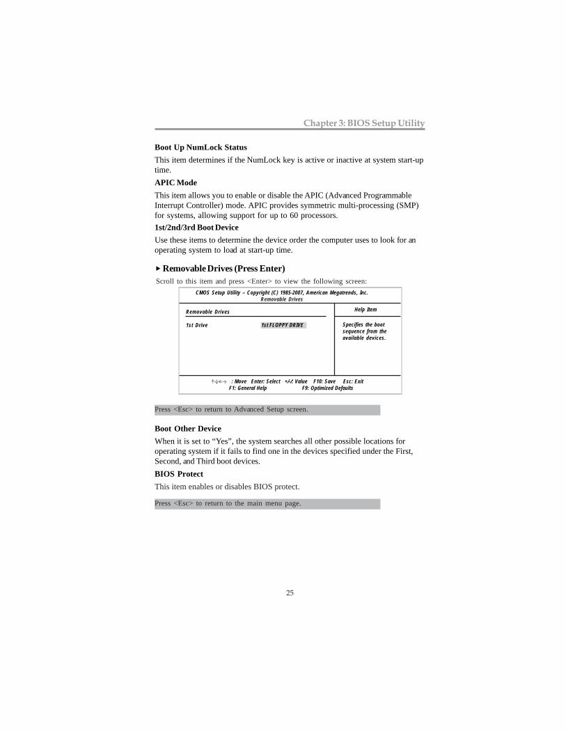
Removable Drives (Press Enter)Scroll to this item and press <Enter> to view the following screen:
Specifies the bootsequence from theavailable devices.
CMOS Setup Utility – Copyright (C) 1985-2007, American Megatrends, Inc.Removable Drives
: Move Enter: Select +/-/: Value F10: Save Esc: Exit F1: General Help F9: Optimized Defaults
Removable Drives
1st Drive
Help Item
1st FLOPPY DRIVE
Press <Esc> to return to Advanced Setup screen.
Boot Up NumLock StatusThis item determines if the NumLock key is active or inactive at system start-uptime.APIC ModeThis item allows you to enable or disable the APIC (Advanced ProgrammableInterrupt Controller) mode. APIC provides symmetric multi-processing (SMP)for systems, allowing support for up to 60 processors.1st/2nd/3rd Boot DeviceUse these items to determine the device order the computer uses to look for anoperating system to load at start-up time.
Boot Other DeviceWhen it is set to “Yes”, the system searches all other possible locations foroperating system if it fails to find one in the devices specified under the First,Second, and Third boot devices.
Press <Esc> to return to the main menu page.
BIOS ProtectThis item enables or disables BIOS protect.
26
Motherboard User’s Guide
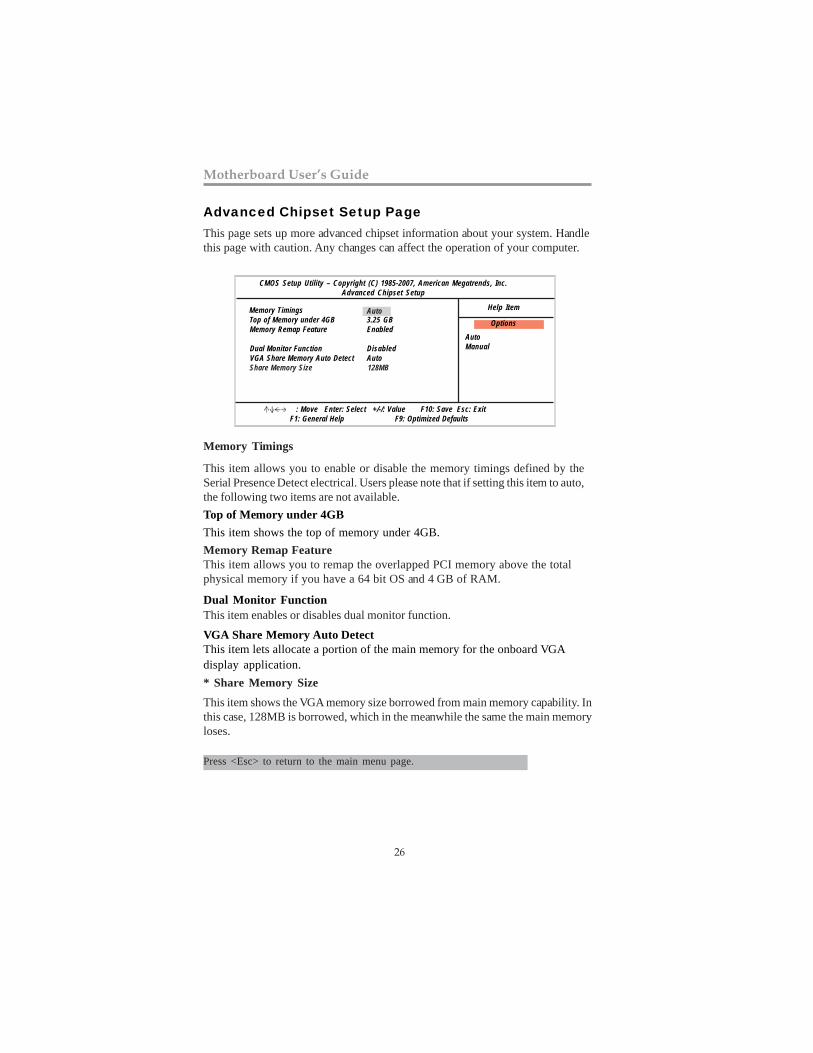
Advanced Chipset Setup PageThis page sets up more advanced chipset information about your system. Handlethis page with caution. Any changes can affect the operation of your computer.
CMOS Setup Utility – Copyright (C) 1985-2007, American Megatrends, Inc.Advanced Chipset Setup
Help Item Memory Timings Top of Memory under 4GB Memory Remap Feature
Dual Monitor Function VGA Share Memory Auto Detect Share Memory Size
3.25 GB Enabled
Disabled Auto 128MB
: Move Enter: Select +/-/: Value F10: Save Esc: Exit F1: General Help F9: Optimized Defaults
AutoManual
Options Auto
Memory Timings
This item allows you to enable or disable the memory timings defined by theSerial Presence Detect electrical. Users please note that if setting this item to auto,the following two items are not available.
* Share Memory Size
This item shows the VGA memory size borrowed from main memory capability. Inthis case, 128MB is borrowed, which in the meanwhile the same the main memoryloses.
Press <Esc> to return to the main menu page.
Dual Monitor FunctionThis item enables or disables dual monitor function.
Memory Remap FeatureThis item allows you to remap the overlapped PCI memory above the totalphysical memory if you have a 64 bit OS and 4 GB of RAM.
Top of Memory under 4GBThis item shows the top of memory under 4GB.
VGA Share Memory Auto DetectThis item lets allocate a portion of the main memory for the onboard VGAdisplay application.
27
Chapter 3: BIOS Setup Utility
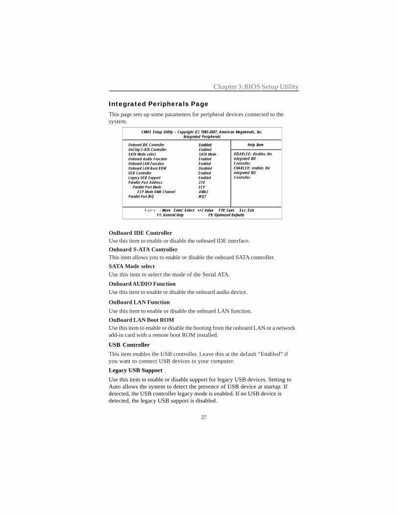
This page sets up some parameters for peripheral devices connected to thesystem.
CMOS Setup Utility – Copyright (C) 1985-2007, American Megatrends, Inc.Integrated Peripherals
Help Item
Integrated Peripherals Page
Onboard IDE Controller EnabledOnChip S-ATA Controller EnabledSATA Mode select SATA ModeOnboard Audio Function EnabledOnboard LAN Function EnabledOnboard LAN Boot ROM DisabledUSB Controller EnabledLegacy USB Support EnabledParallel Port Address 378 Parallel Port Mode ECP ECP Mode DMA Channel DMA3Parallel Port IRQ IRQ7
OnBoard IDE Controller
Onboard S-ATA Controller
OnBoard LAN FunctionUse this item to enable or disable the onboard LAN function.OnBoard LAN Boot ROMUse this item to enable or disable the booting from the onboard LAN or a networkadd-in card with a remote boot ROM installed.
Onboard AUDIO Function
Use this item to enable or disable the onboard IDE interface.
This item allows you to enable or disable the onboard SATA controller.SATA Mode select
Use this item to enable or disable the onboard audio device.
Use this item to select the mode of the Serial ATA.
Legacy USB SupportUse this item to enable or disable support for legacy USB devices. Setting toAuto allows the system to detect the presence of USB device at startup. Ifdetected, the USB controller legacy mode is enabled. If no USB device isdetected, the legacy USB support is disabled.
This item enables the USB controller. Leave this at the default “Enabled” ifyou want to connect USB devices to your computer.
USB Controller
DISABLED: disables theintegrated IDEController.ENABLED: enables theintegrated IDEController.
: Move Enter: Select +/-/: Value F10: Save Esc: Exit F1: General Help F9: Optimized Defaults
28
Motherboard User’s Guide
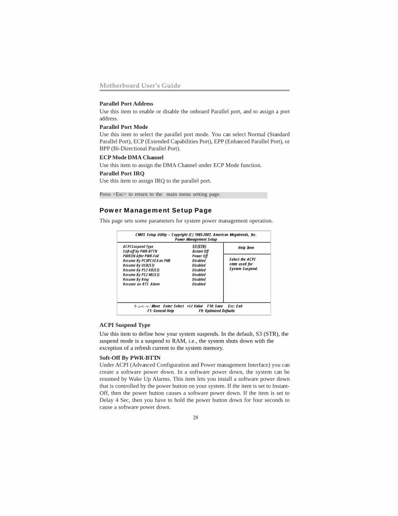
Power Management Setup PageThis page sets some parameters for system power management operation.
ACPI Suspend TypeUse this item to define how your system suspends. In the default, S3 (STR), thesuspend mode is a suspend to RAM, i.e., the system shuts down with theexception of a refresh current to the system memory.
CMOS Setup Utility – Copyright (C) 1985-2007, American Megatrends, Inc.Power Management Setup
Help Item
Select the ACPIstate used forSystem Suspend.
Press <Esc> to return to the main menu setting page.
: Move Enter: Select +/-/: Value F10: Save Esc: Exit F1: General Help F9: Optimized Defaults
ACPI Suspend Type S3 (STR)Soft-off by PWR-BTTN Instant OffPWRON After PWR-Fail Power OffResume By PCI/PCI-E/Lan PME DisabledResume By USB(S3) DisabledResume By PS2 KB(S3) DisabledResume By PS2 MS(S3) DisabledResume By Ring DisabledResume on RTC Alarm Disabled
Parallel Port Mode
ECP Mode DMA ChannelUse this item to assign the DMA Channel under ECP Mode function.Parallel Port IRQUse this item to assign IRQ to the parallel port.
Use this item to select the parallel port mode. You can select Normal (StandardParallel Port), ECP (Extended Capabilities Port), EPP (Enhanced Parallel Port), orBPP (Bi-Directional Parallel Port).
Parallel Port AddressUse this item to enable or disable the onboard Parallel port, and to assign a portaddress.
Soft-Off By PWR-BTTNUnder ACPI (Advanced Configuration and Power management Interface) you cancreate a software power down. In a software power down, the system can beresumed by Wake Up Alarms. This item lets you install a software power downthat is controlled by the power button on your system. If the item is set to Instant-Off, then the power button causes a software power down. If the item is set toDelay 4 Sec, then you have to hold the power button down for four seconds tocause a software power down.
29
Chapter 3: BIOS Setup Utility
Press <Esc> to return to the main menu setting page.
Resume By PCI/PCI-E/Lan PMEThese items specify whether the system will be awakened from power savingmodes when activity or input signal of the specified hardware peripheral or compo-nent is detected.Resume By USB(S3)This item allows you to enable/disable the USB device wakeup function from S3/S4mode.
PWRON After PWR-FailThis item enables your computer to automatically restart or return to its operatingstatus.
Resume By PS2 KB(S3)This item enable or disable you to allow keyboard activity to awaken the systemfrom power saving mode.Resume By PS2 MS(S3)This item enable or disable you to allow mouse activity to awaken the system frompower saving mode.Resume By RingAn input signal on the serial Ring Indicator (RI) line (in other words, an incomingcall on the modem) awakens the system from a soft off state.
Resume on RTC AlarmThe system can be turned off with a software command. If you enable this item, thesystem can automatically resume at a fixed time based on the system’s RTC(realtime clock). Use the items below this one to set the date and time of the wake-up alarm. You must use an ATX power supply in order to use this feature.
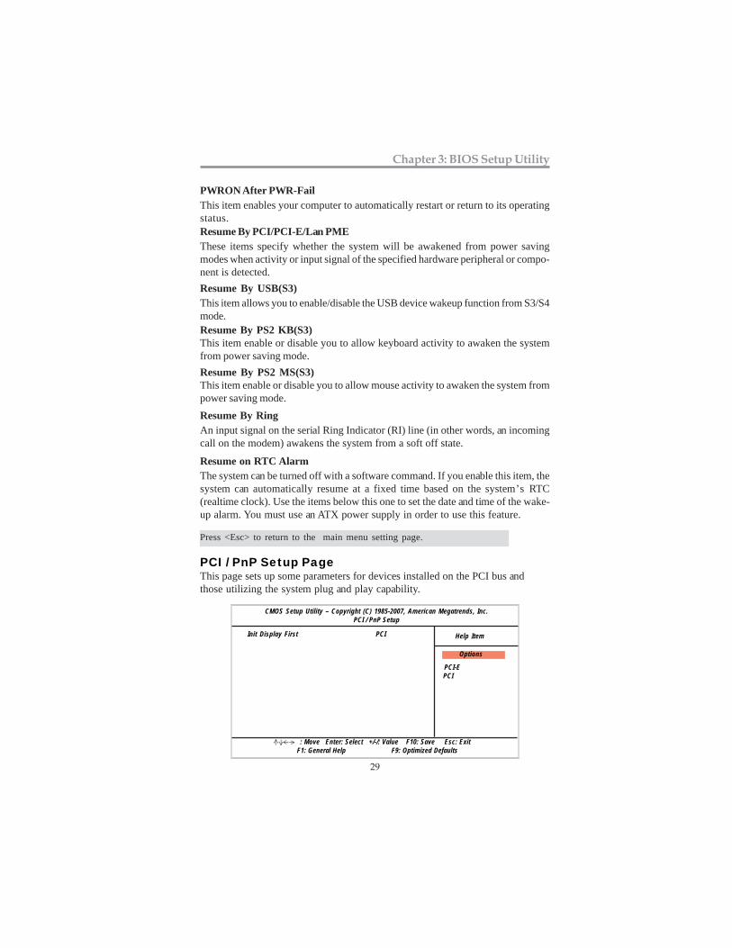
This page sets up some parameters for devices installed on the PCI bus andthose utilizing the system plug and play capability.
PCI / PnP Setup Page
CMOS Setup Utility – Copyright (C) 1985-2007, American Megatrends, Inc.PCI / PnP Setup
Init Display First PCI Help Item
: Move Enter: Select +/-/: Value F10: Save Esc: Exit F1: General Help F9: Optimized Defaults
PCI-E PCI
Options
30
Motherboard User’s Guide
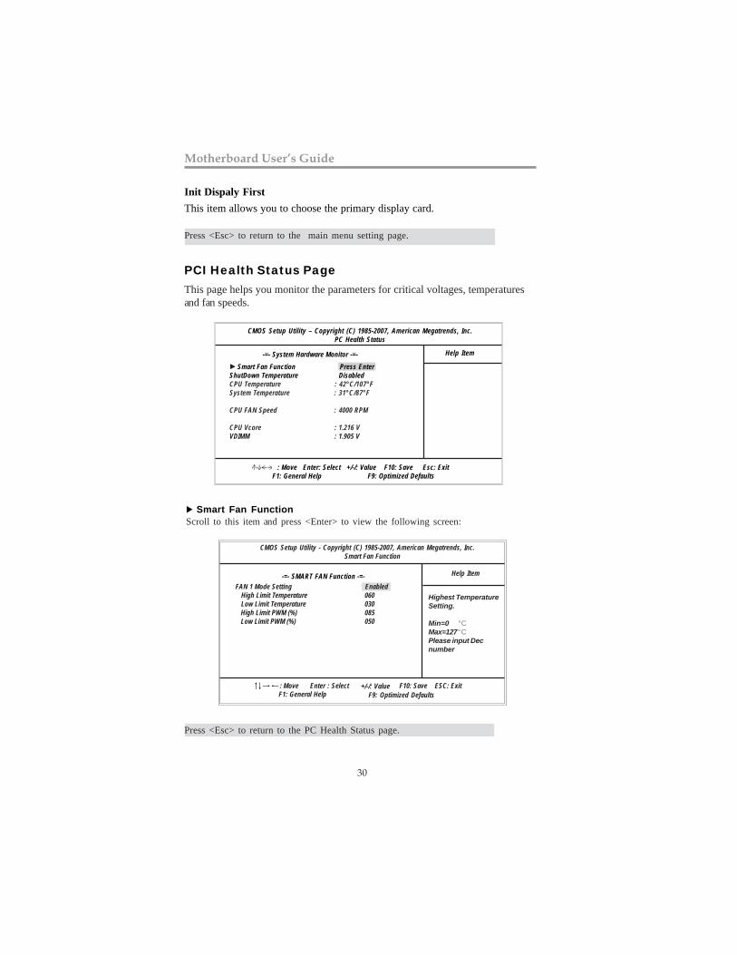
Smart Fan Function Press EnterShutDown Temperature DisabledCPU Temperature : 42°C/107°FSystem Temperature : 31°C/87°F
CPU FAN Speed : 4000 RPM
CPU Vcore : 1.216 VVDIMM : 1.905 V
Init Dispaly FirstThis item allows you to choose the primary display card.
PCI Health Status PageThis page helps you monitor the parameters for critical voltages, temperaturesand fan speeds.
CMOS Setup Utility – Copyright (C) 1985-2007, American Megatrends, Inc.PC Health Status
Help Item
: Move Enter: Select +/-/: Value F10: Save Esc: Exit F1: General Help F9: Optimized Defaults
-=- System Hardware Monitor -=-
Press <Esc> to return to the main menu setting page.
Smart Fan FunctionScroll to this item and press <Enter> to view the following screen:
CMOS Setup Utility - Copyright (C) 1985-2007, American Megatrends, Inc. Smart Fan Function
-=- SMART FAN Function -=-
Highest TemperatureSetting.
Min=0 °CMax=127°CPlease input Decnumber
Help Item
: Move Enter : Select +/-/: ValueF9: Optimized DefaultsF1: General Help
F10: Save ESC: Exit
FAN 1 Mode Setting Enabled High Limit Temperature 060 Low Limit Temperature 030 High Limit PWM (%) 085 Low Limit PWM (%) 050
Press <Esc> to return to the PC Health Status page.
31
Chapter 3: BIOS Setup Utility
System Component CharacteristicsThese fields provide you with information about the system current operatingstatus.
• CPU Temperature• System Temperature• CPU Fan Speed• CPU Vorce• VDIMM
Press <Esc> to return to the main menu setting page.
CMOS Setup Utility – Copyright (C) 1985-2007, American Megatrends, Inc.Frequncey/Voltage Control
Help Item
: Move Enter: Select +/-/: Value F10: Save Esc: Exit F1: General Help F9: Optimized Defaults
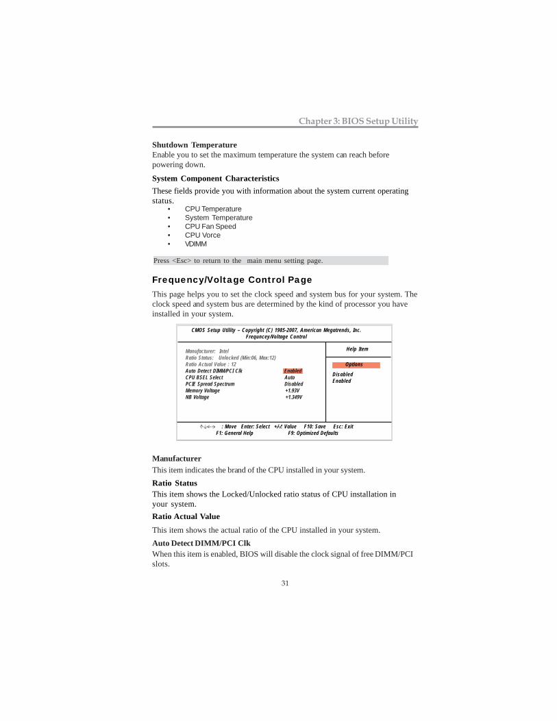
Frequency/Voltage Control PageThis page helps you to set the clock speed and system bus for your system. Theclock speed and system bus are determined by the kind of processor you haveinstalled in your system.
DisabledEnabled
Options
Manufacturer: IntelRatio Status: Unlocked (Min:06, Max:12)Ratio Actual Value : 12Auto Detect DIMM/PCI Clk EnabledCPU BSEL Select AutoPCIE Spread Spectrum DisabledMemory Voltage +1.93VNB Voltage +1.349V
ManufacturerThis item indicates the brand of the CPU installed in your system.
Shutdown TemperatureEnable you to set the maximum temperature the system can reach beforepowering down.
Ratio Actual Value
This item shows the actual ratio of the CPU installed in your system.
Ratio StatusThis item shows the Locked/Unlocked ratio status of CPU installation inyour system.
Auto Detect DIMM/PCI ClkWhen this item is enabled, BIOS will disable the clock signal of free DIMM/PCIslots.
32
Motherboard User’s Guide
PCIE Spread SpectrumIf you enable spread spectrum, it can significantly reduce the EMI (Electro-Magnetic interface) generated by the PCIE.
Load Default SettingsThis option opens a dialog box to ask if you are sure to install optimizeddefaults or not. You select [OK], and then <Enter>, the Setup Utility loads alldefault values; or select [Cancel], and then <Enter>, the Setup Utility does notload default values.
Note: It is highly recommend that users enter this option to load optimal defaultvalues for accessing the best performance.
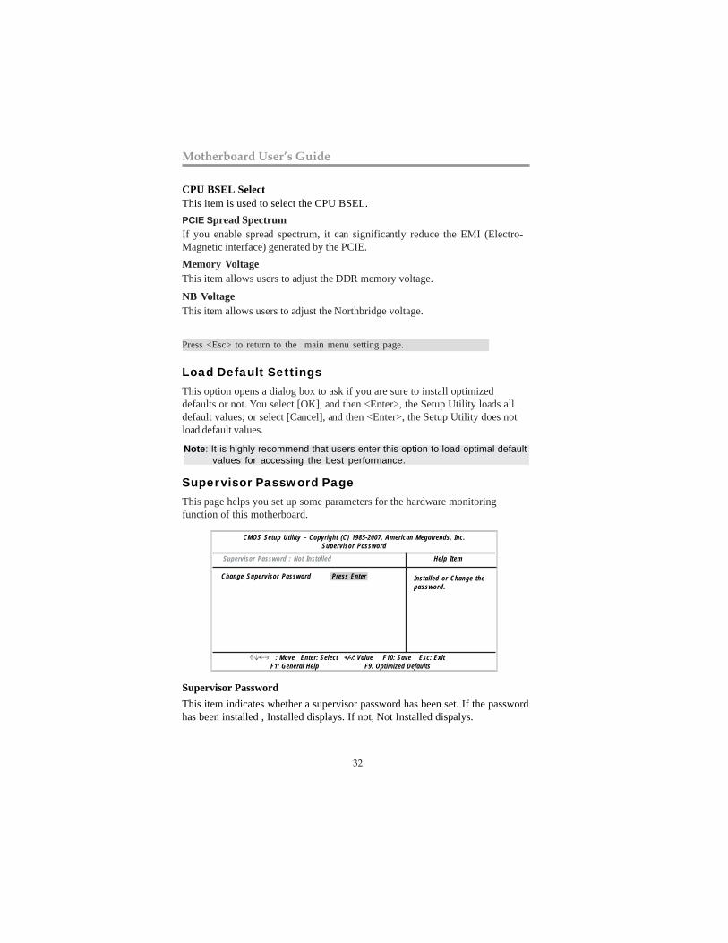
Supervisor Password PageThis page helps you set up some parameters for the hardware monitoringfunction of this motherboard.
CMOS Setup Utility – Copyright (C) 1985-2007, American Megatrends, Inc.Supervisor Password
Help Item
: Move Enter: Select +/-/: Value F10: Save Esc: Exit F1: General Help F9: Optimized Defaults
Supervisor Password : Not Installed
Change Supervisor Password Installed or Change thepassword.
Press Enter
Supervisor PasswordThis item indicates whether a supervisor password has been set. If the passwordhas been installed , Installed displays. If not, Not Installed dispalys.
Memory VoltageThis item allows users to adjust the DDR memory voltage.
CPU BSEL SelectThis item is used to select the CPU BSEL.
Press <Esc> to return to the main menu setting page.
NB VoltageThis item allows users to adjust the Northbridge voltage.
33
Chapter 3: BIOS Setup Utility
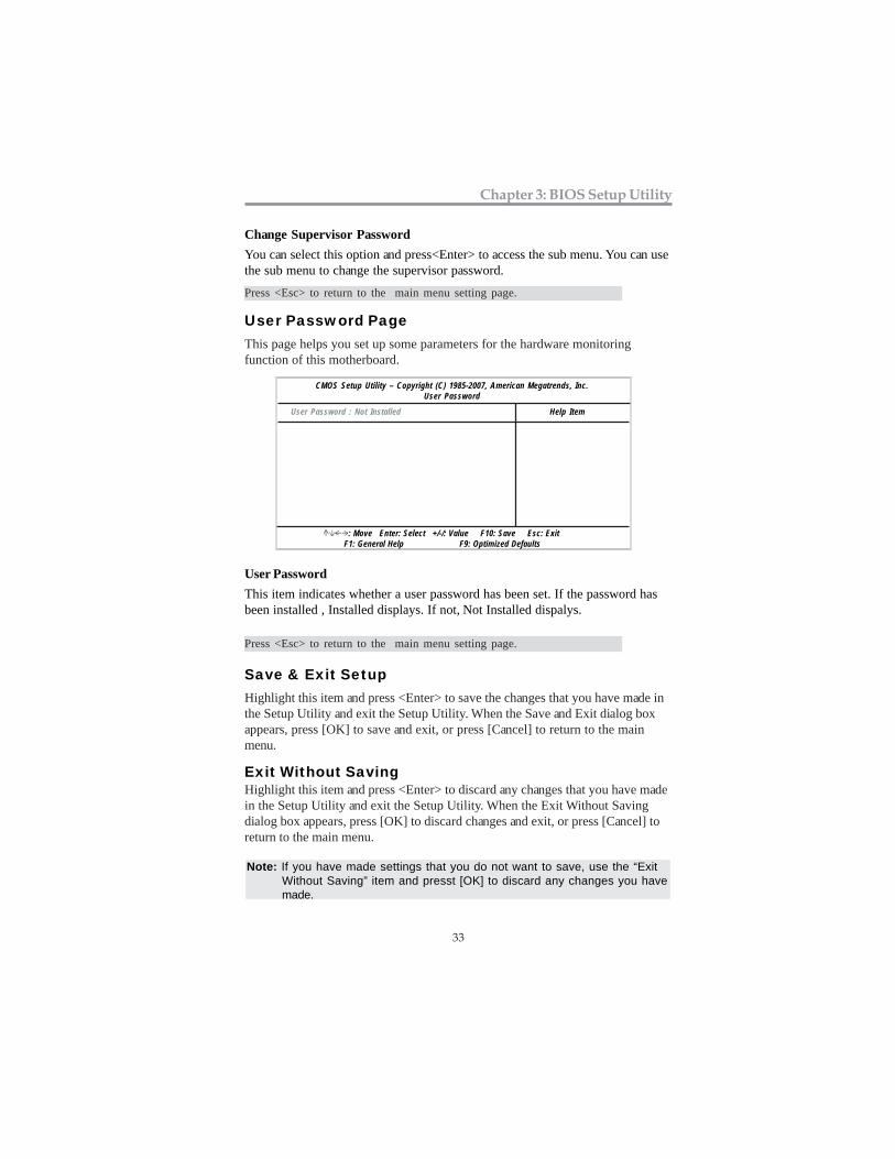
User PasswordThis item indicates whether a user password has been set. If the password hasbeen installed , Installed displays. If not, Not Installed dispalys.
Save & Exit SetupHighlight this item and press <Enter> to save the changes that you have made inthe Setup Utility and exit the Setup Utility. When the Save and Exit dialog boxappears, press [OK] to save and exit, or press [Cancel] to return to the mainmenu.
Exit Without SavingHighlight this item and press <Enter> to discard any changes that you have madein the Setup Utility and exit the Setup Utility. When the Exit Without Savingdialog box appears, press [OK] to discard changes and exit, or press [Cancel] toreturn to the main menu.
Change Supervisor PasswordYou can select this option and press<Enter> to access the sub menu. You can usethe sub menu to change the supervisor password.
CMOS Setup Utility – Copyright (C) 1985-2007, American Megatrends, Inc.User Password
Help Item
: Move Enter: Select +/-/: Value F10: Save Esc: Exit F1: General Help F9: Optimized Defaults
User Password : Not Installed
User Password PageThis page helps you set up some parameters for the hardware monitoringfunction of this motherboard.
Note: If you have made settings that you do not want to save, use the “ExitWithout Saving” item and presst [OK] to discard any changes you havemade.
Press <Esc> to return to the main menu setting page.
Press <Esc> to return to the main menu setting page.
34
Motherboard User’s Guide
Chapter 4 Software & Applications
IntroductionThis chapter describes the contents of the support CD-ROM that comes with themotherboard package.
The support CD-ROM contains all useful software, necessary drivers and utilityprograms to properly run our products. More program information is available ina README file, located in the same directory as the software.
To run the support CD, simply insert the CD into your CD-ROM drive. An AutoSetup screen automatically pops out, and then you can go on the auto-installing ormanual installation depending on your operating system.
If your operating system is Windows 2000/XP/Vista, it will automatically installall the drivers and utilities for your motherboard.
Installing Support Software1 Insert the support CD-ROM disc in the CD-ROM drive.2 When you insert the CD-ROM disc in the system CD-ROM drive,
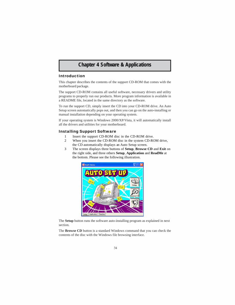
the CD automatically displays an Auto Setup screen.3 The screen displays three buttons of Setup, Browse CD and Exit on
the right side, and three others Setup, Application and ReadMe atthe bottom. Please see the following illustration.
The Setup button runs the software auto-installing program as explained in nextsection.
The Browse CD button is a standard Windows command that you can check thecontents of the disc with the Windows file browsing interface.
35
Chapter 4: Software & Applications
The Exit button closes the Auto Setup window. To run the program again, reinsertthe CD-ROM disc in the drive; or click the CD-ROM driver from the WindowsExplorer, and click the Setup icon.
The Application button brings up a software menu. It shows the bundled softwarethat this mainboard supports.
The ReadMe brings you to the Install Path where you can find out path names ofsoftware driver.
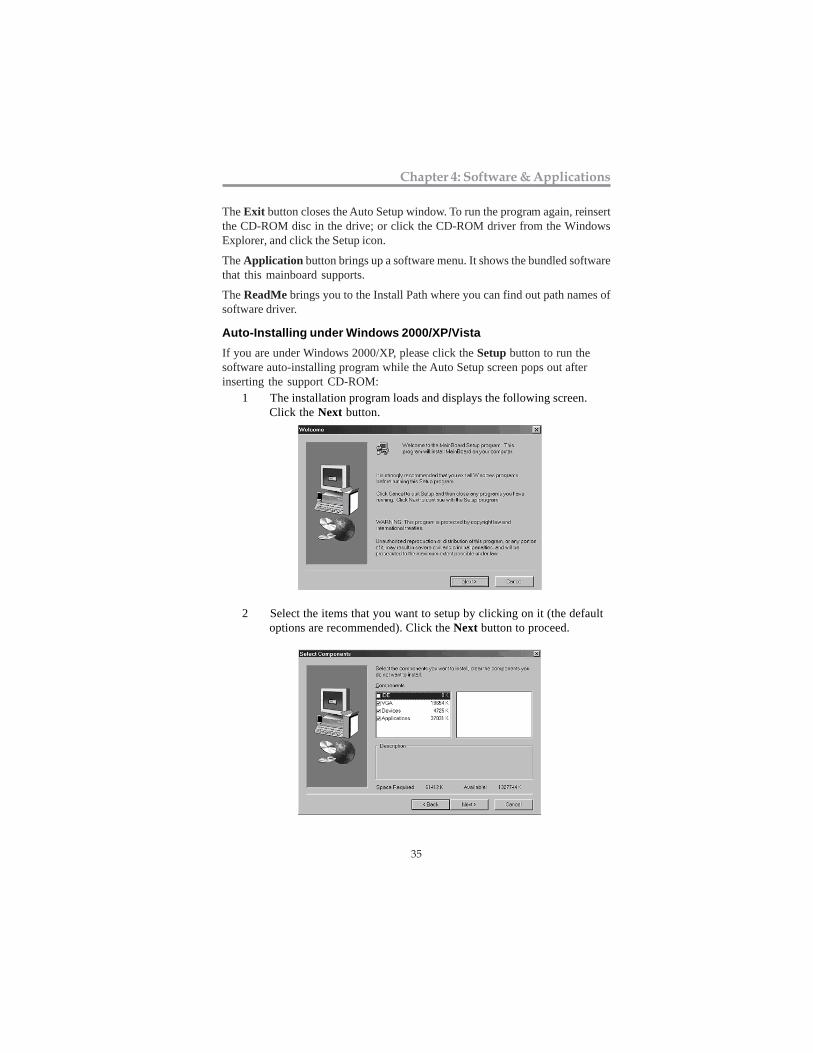
Auto-Installing under Windows 2000/XP/VistaIf you are under Windows 2000/XP, please click the Setup button to run thesoftware auto-installing program while the Auto Setup screen pops out afterinserting the support CD-ROM:
1 The installation program loads and displays the following screen.Click the Next button.
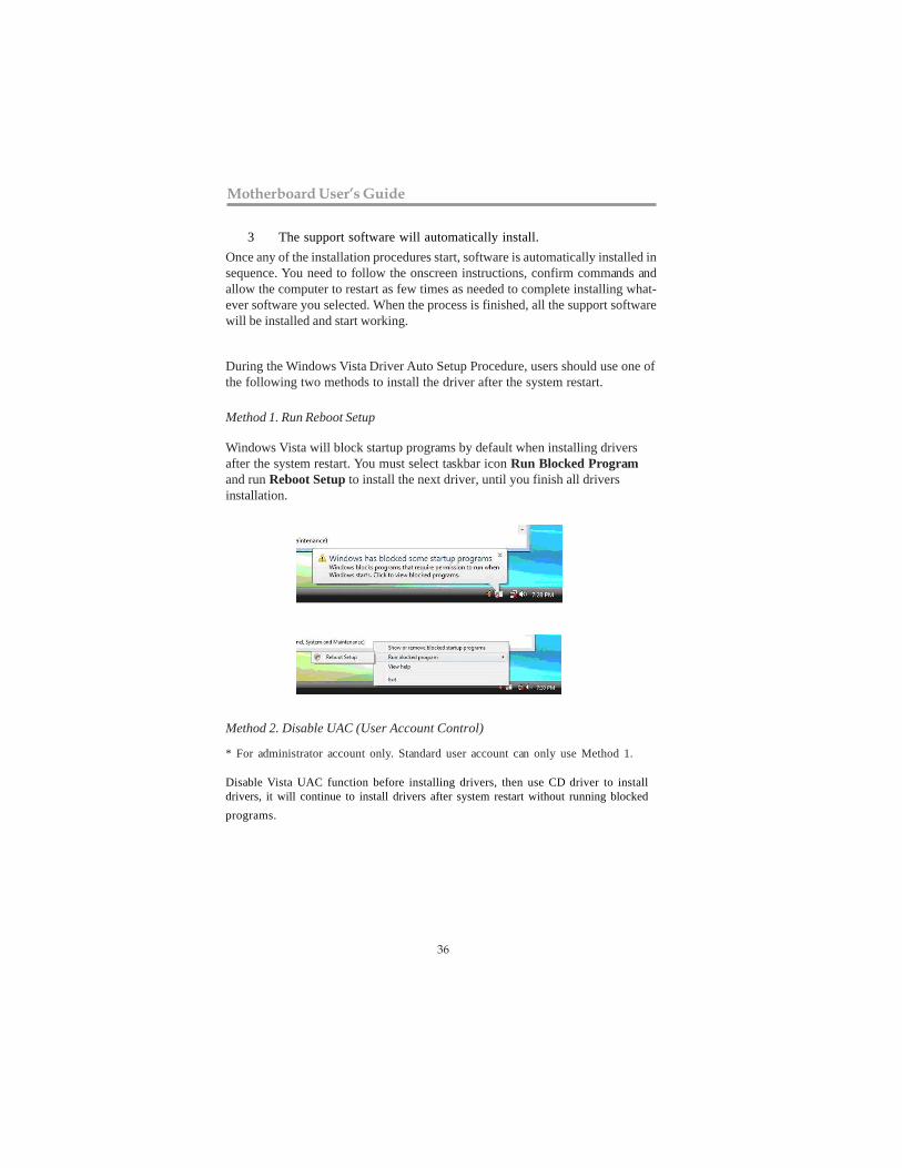
2 Select the items that you want to setup by clicking on it (the defaultoptions are recommended). Click the Next button to proceed.
36
Motherboard User’s Guide
3 The support software will automatically install.Once any of the installation procedures start, software is automatically installed insequence. You need to follow the onscreen instructions, confirm commands andallow the computer to restart as few times as needed to complete installing what-ever software you selected. When the process is finished, all the support softwarewill be installed and start working.
During the Windows Vista Driver Auto Setup Procedure, users should use one ofthe following two methods to install the driver after the system restart.
Method 1. Run Reboot Setup
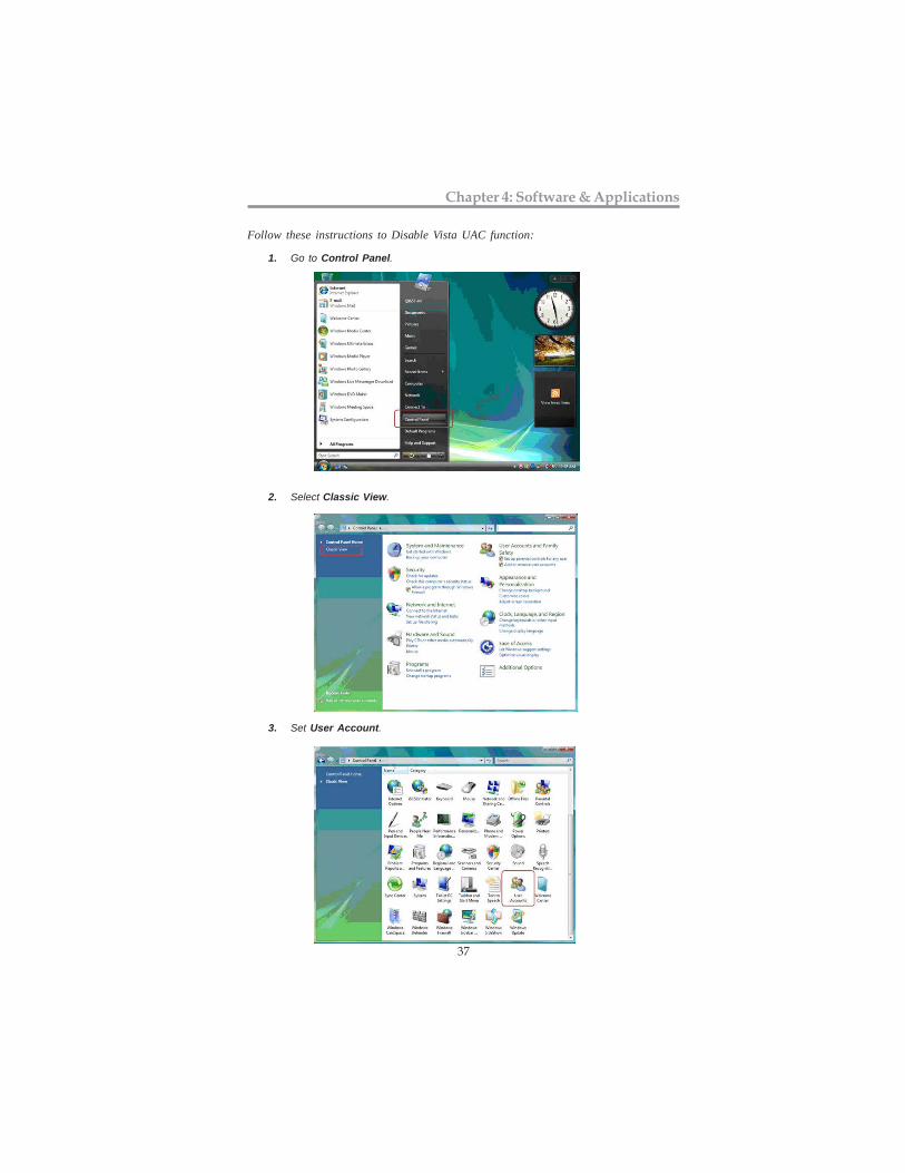
Windows Vista will block startup programs by default when installing driversafter the system restart. You must select taskbar icon Run Blocked Programand run Reboot Setup to install the next driver, until you finish all driversinstallation.
Method 2. Disable UAC (User Account Control)
* For administrator account only. Standard user account can only use Method 1.
Disable Vista UAC function before installing drivers, then use CD driver to installdrivers, it will continue to install drivers after system restart without running blockedprograms.
37
Chapter 4: Software & Applications
Follow these instructions to Disable Vista UAC function:
1. Go to Control Panel.
2. Select Classic View.
3. Set User Account.
38
Motherboard User’s Guide
Bundled Software InstallationAll bundled software available on the CD-ROM is for users’ convenience. You caninstall bundled software as follows:
1 Click the Application button while the Auto Setup screen pops outafter inserting the support CD-ROM.
2 A software menu appears. Click the software you want to install.3 Follow onscreen instructions to install the software program step by
step until finished.
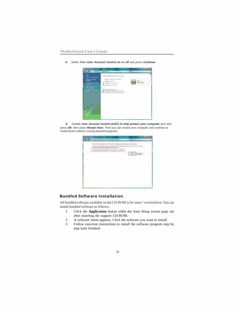
4. Select Turn User Account Control on or off and press Continue.
5. Disable User Account Control (UAC) to help protect your computer item andpress OK, then press Restart Now. Then you can restart your computer and continue toinstall drivers without running blocked programs.


![Welcome [unisonfgpartners.com.au]unisonfgpartners.com.au/pdf/FINDEX-FMGMT.pdf4.0 1.0 1.0 1.0 1.0 1.0 1.0 50.0 43.5 34.5 25.5 12.5 5.5 9.0 9.0 8.0 7.0 5.0 2.0 5.0 5.0 5.0 5.0 5.0 14.0](https://img.pdfslide.us/doc/110x75/5f9881d4934d305cce543099/welcome-40-10-10-10-10-10-10-500-435-345-255-125-55-90-90-80.jpg)