Embed Size (px)
Citation preview

P3K Infrastructure – July 19, 2010
P3K Palomar Infrastructure
Balance AdaptationsLarger Cass weight load
Electrical Service UpgradesHigher electric service loads at Cass, Computer Room and
AO lab
Cooling of Cass Electronic RacksRemoval of ~6kW of heat from below primary mirror
J.Zolkower 1

P3K Infrastructure – July 19, 2010
Cass Mounted System Weights
Current AO Cass System Weights AO Bench 3820 lb AO Rack 1 (Loc 3) 415 lb AO Rack 2 (Loc 2) 345 lb Cables 85 lb (est)
Total 4665 lbs
P3K AO Cass System Weights P3K Bench 3900 lb P3K DM rack 1 (Loc 3) 525 lb P3K DM rack 2 (Loc 2) 525 lb P3K Ctrl rack 1 (Loc 5) 258 lb P3K Ctrl rack 2 (Loc 4) 348 lb Cables 475 lb Glycol system hardware 260 lb
Total 6291 lb (~1600 lbs > current AO)J.Zolkower 2
P3K Infrastructure – July 19, 2010
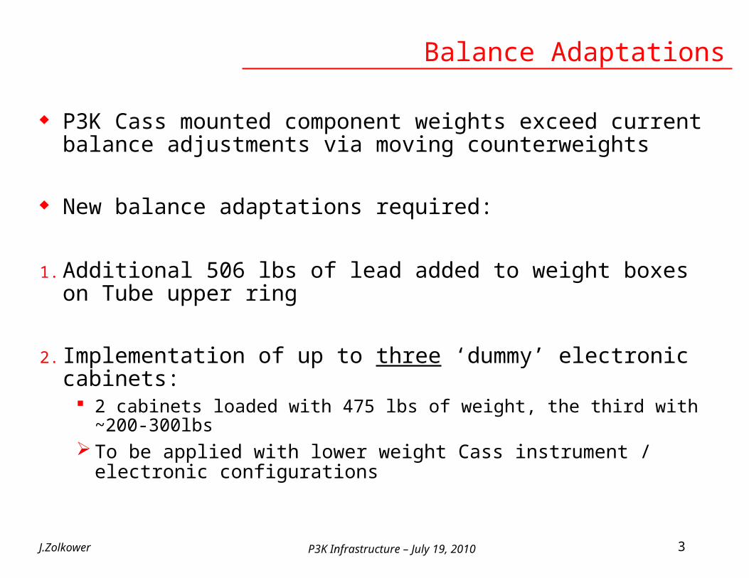
P3K Cass mounted component weights exceed current balance adjustments via moving counterweights
New balance adaptations required:
1. Additional 506 lbs of lead added to weight boxes on Tube upper ring
2. Implementation of up to three ‘dummy’ electronic cabinets: 2 cabinets loaded with 475 lbs of weight, the third with ~200-300lbs To be applied with lower weight Cass instrument / electronic
configurations
J.Zolkower 3
Balance Adaptations
P3K Infrastructure – July 19, 2010
Electrical Service Upgrades
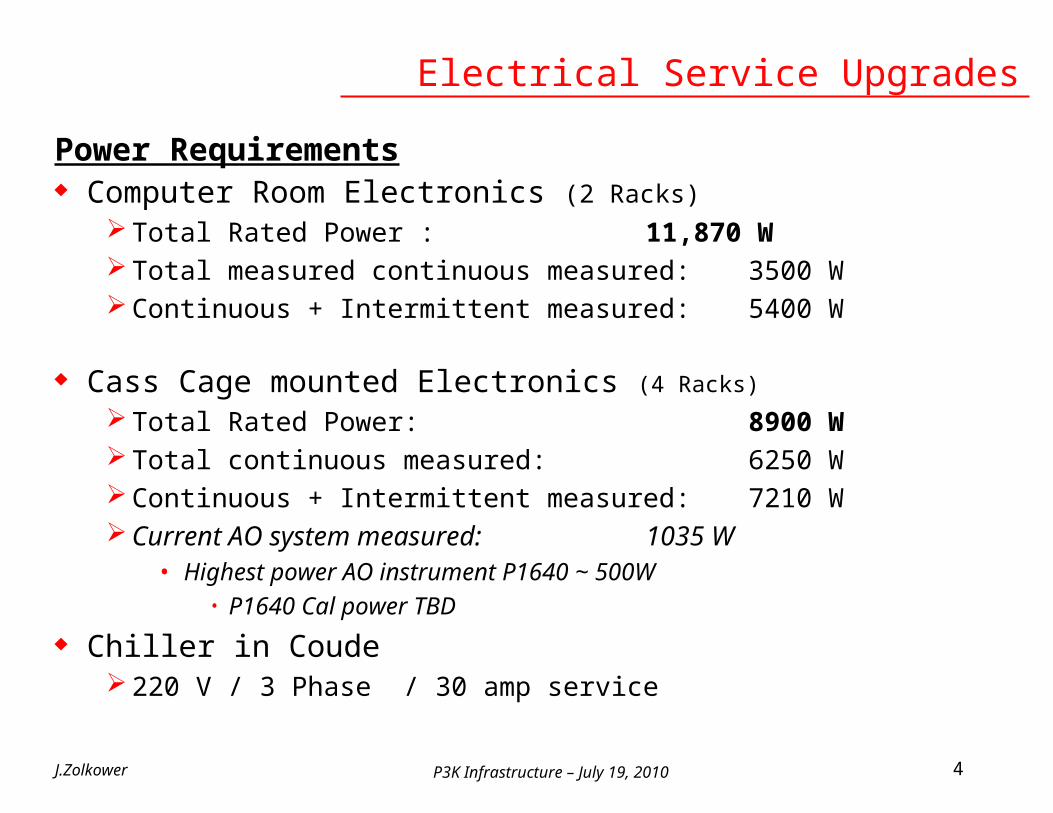
Power Requirements Computer Room Electronics (2 Racks)
Total Rated Power : 11,870 W Total measured continuous measured: 3500 W Continuous + Intermittent measured: 5400 W
Cass Cage mounted Electronics (4 Racks)
Total Rated Power: 8900 W Total continuous measured: 6250 W Continuous + Intermittent measured: 7210 W Current AO system measured: 1035 W
• Highest power AO instrument P1640 ~ 500W• P1640 Cal power TBD
Chiller in Coude 220 V / 3 Phase / 30 amp service
J.Zolkower 4
P3K Infrastructure – July 19, 2010
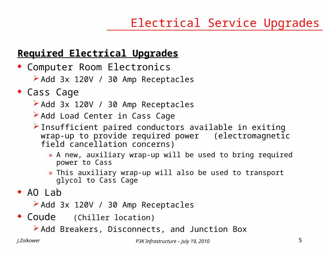
Required Electrical Upgrades Computer Room Electronics
Add 3x 120V / 30 Amp Receptacles
Cass Cage Add 3x 120V / 30 Amp Receptacles Add Load Center in Cass Cage Insufficient paired conductors available in exiting wrap-up to provide
required power (electromagnetic field cancellation concerns)» A new, auxiliary wrap-up will be used to bring required power to Cass» This auxiliary wrap-up will also be used to transport glycol to Cass Cage
AO Lab Add 3x 120V / 30 Amp Receptacles
Coude (Chiller location)
Add Breakers, Disconnects, and Junction Box
J.Zolkower 5
Electrical Service Upgrades

P3K Infrastructure – July 19, 2010
Power Dissipation / Mirror Temperature
J.Zolkower 6
3
4
5
6
7
8
9
10
11
12
13M
irro
r Tem
pera
ture
(ºC)
Month/Day: UT Time
200" Mirror Temperature
N
NE
E
SE
S
SW
W
NW
AO power on AO power off
CO2 cleaningcaused rapid cooling
24 hour data gap
Sensor Location
Current AO power ~ 1000 W

P3K Infrastructure – July 19, 2010
Maximum Heat Dissipation Requirement
Specification released May 5, 2010:
1) For all Cassegrain mounted instruments, the maximum heat dissipation shall not exceed 300W under the primary mirror, and 1 kW into the dome air away from the primary mirror. If this requirement is met, it is assumed that the following requirements will also be met except under extreme circumstances.
a The heat dissipated by any Cassegrain mounted instrument shall not increase the temperature of the primary mirror, locally or globally, by more than 0.75ºC relative to the mirror baseline temperature.
b The heat dissipated by any Cassegrain mounted instrument shall not induce a temperature gradient in the mirror of more than 0.5ºC measured between any two points on the mirror.
I. Evaluation of items 1a. and 1b. to be made by comparing values using a 12 point moving average of data taken at a 5 minute sampling rate.
II. The baseline temperature is defined as the average of the primary mirror temperature measured at the north and northeast temperature sensor locations.
J.Zolkower 7

P3K Infrastructure – July 19, 2010
Cass Rack Power Allocation
J.Zolkower 8
RACK ID
MEASURED CONTINUOUS
POWER (W)
MEASURED Intermittent
POWER(W)
DM 1 2,420 2,420DM 2 2,420 2,420
Cass 1 1,270 1,270Cass 2 140 1,080
Total 6,250 7,210
These racks to be cooled~6100 W

P3K Infrastructure – July 19, 2010
Cooling System Functional Parameters
Basic Functional Requirement Provide system for cooling of Cass mounted electronics in order to
minimize the heat dissipated to environment below the primary mirror and dome air
Operating parameters: Ambient temperature range: -10ºC to +30ºC Target Coolant temperature: 3ºC below ambient Cooling fan air flow: Constant speed Coolant Mix: 35% Propylene Glycol Coolant Temperature Range: -13ºC to +27ºC Heat expelled to facility chilled water 5ºC to 10ºC (seasonal range) Facility chiller total capacity 10 ton ( 35 kW) Facility chiller current heat load ~ 1 ¾ ton (~6.2 kW)
Thermal modeling of electronic rack heat exchangers by Thermatron to confirm heat exchanger design within proposed operating parameters
J.Zolkower 9

P3K Infrastructure – July 19, 2010
Electronic Rack Heat Exchanger
J.Zolkower 10

P3K Infrastructure – July 19, 2010
Heat Exchanger Thermal Model Results
J.Zolkower 11
DM Rack High Temperature 550 cfm Air flow 440 cfm Air flow2420 W total heat load 2 heat exchangers 3 heat exchangers
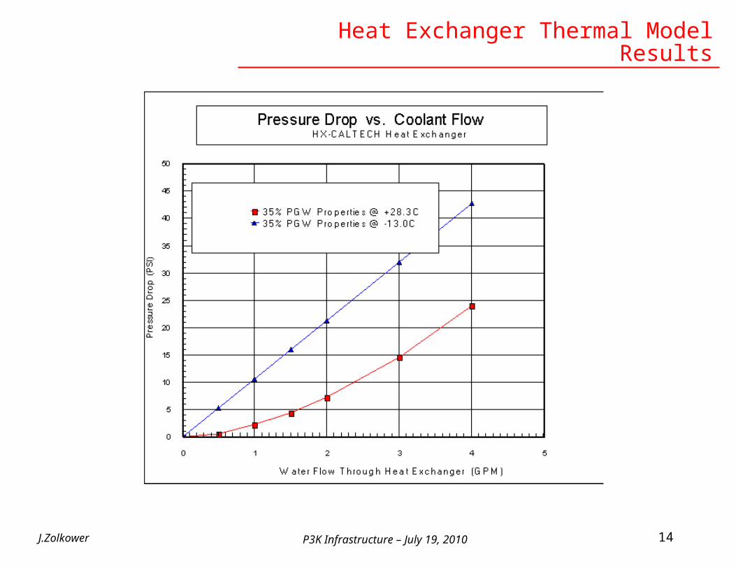
Coolant Flow 2 GPM 2 GPMCoolant Temp entering HX 27.0C 27.0C Coolant Temp exiting HX 29.4C 28.6CCoolant pressure drp thru HX 7.4 PSIG 7.4 PSIGAir Temp entering HX 34.7C 32.8CAir Temp exiting HX 30.1C 28.9CAir pressure drop 0.30" w.c. 0.20" w.c. Heat exchanger performance 156 W/C 137 W/CHeat Load /HX 1205 Watts 800 Watts
DM Rack Low Temperature 550 cfm Air flow 440 cfm Air flow2420 W total heat load 2 heat exchangers 3 heat exchangers
Coolant Flow 2 GPM 2 GPMCoolant Temp entering HX -13.0C -13.0C Coolant Temp exiting HX -10.6C -11.4CCoolant pressure drp thru HX 21.4 PSIG 21.4 PSIGAir Temp entering HX -6.4C -8.1CAir Temp exiting HX -11.1C -11.9CAir pressure drop 0.30" w.c. 0.20" w.c. Heat exchanger performance 182 W/C 162 W/CHeat Load /HX 1202 Watts 800 Watts

P3K Infrastructure – July 19, 2010J.Zolkower 12
Cass Rack 1 High Temperature 550 cfm Air flow 440 cfm Air flow1270 W Total Heat Load 1 heat exchanger 2 heat exchangers
Coolant Flow / HX 2.5 GPM 2 GPMCoolant Temp entering HX 27.0C 27.0C Coolant Temp exiting HX 29.1C 28.3CCoolant pressure drp thru HX 11 PSIG 7.4 PSIGAir Temp entering HX 34.8C 31.6C
Air Temp exiting HX 29.8C 28.6C
Air pressure drop 0.30" w.c. 0.20" w.c. Heat exchanger performance 163 W/C 137 W/CHeat Load /HX 1270 Watts 633 Watts
Cass Rack 1 Low Temperature 550 cfm Air flow 440 cfm Air flow1270 W Total Heat Load 1 heat exchanger 2 heat exchangers
Coolant Flow 2.5 GPM 2 GPMCoolant Temp entering HX -13.0C -13.0C Coolant Temp exiting HX -10.9C -11.7CCoolant pressure drp thru HX 27 PSIG 21.4 PSIGAir Temp entering HX -6.6C -9.1C
Air Temp exiting HX -11.5C -12.2C
Air pressure drop 0.30" w.c. 0.20" w.c. Heat exchanger performance 198 W/C 162 W/C
Heat Load /HX 1275 Watts 638 Watts
Heat Exchanger Thermal Model Results
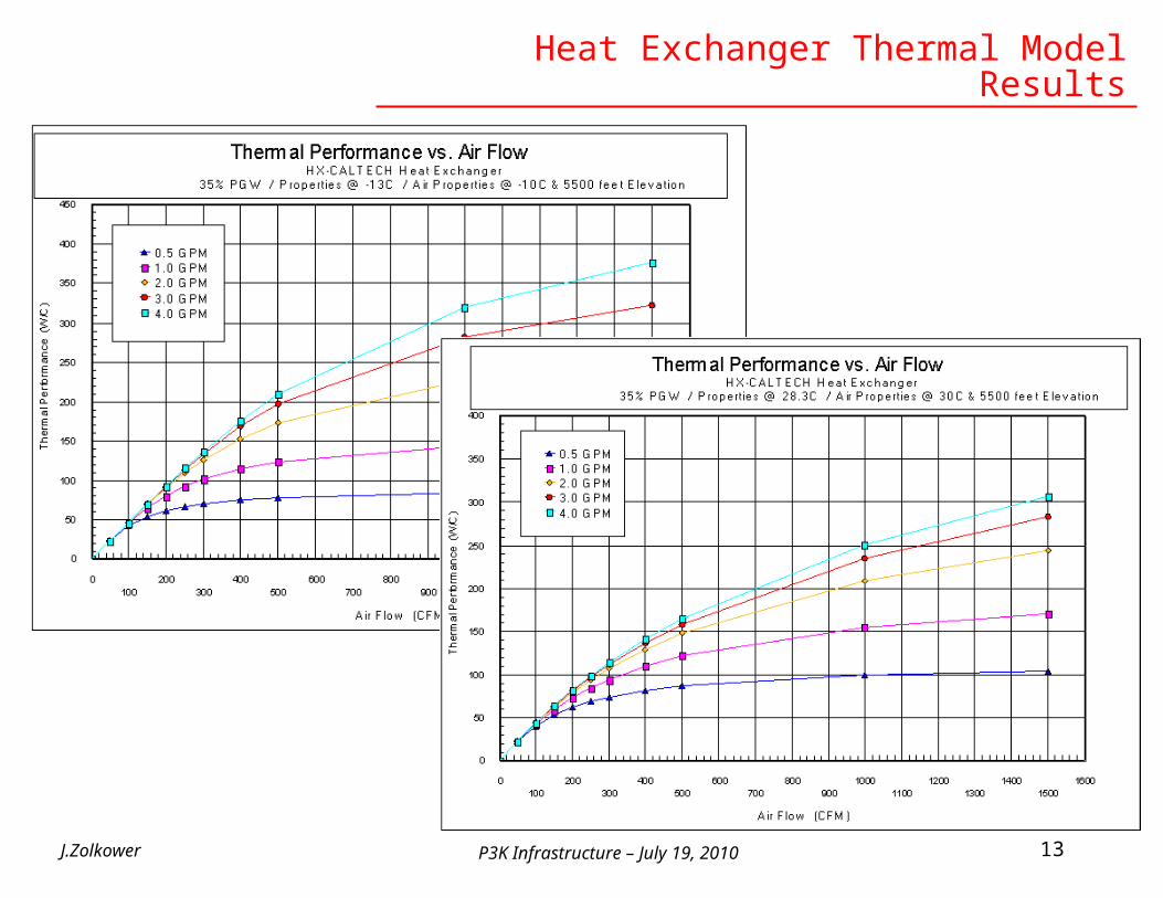
P3K Infrastructure – July 19, 2010J.Zolkower 13
Heat Exchanger Thermal Model Results
P3K Infrastructure – July 19, 2010J.Zolkower 14
Heat Exchanger Thermal Model Results

P3K Infrastructure – July 19, 2010
Chiller Specification
Total heat load: 6100 W Max. coolant flow rate: 16 GPM
DM Racks: 3x 2 gpm x 2 Racks = 12 gpm Cass 1 Rack: 2x 2 gpm x 1 Rack = 4 gpm
Coldest required supply coolant temp: -13ºC Warmest required supply coolant temp: +27ºC
Chiller Construction / Installation Options for Cass: Air cooled unit: exhaust chiller warm air directly out dome by most direct route on dome
floor. B) Air cooled unit: exhaust chiller warm air through Buffalo Blower exhaust. C) Air cooled unit: Split system with refrig condenser outside. D) Water cooled unit: exhaust chiller heat through facility chilled water. E) Water cooled unit: exhaust chiller heat through connection to 2nd closed cycle coolant
system via outside heat exchanger.
Chiller Construction / Installation Options for AO Lab: Acquired Neslab System III & IV Liquid to Liquid Heat Exchangers Cooling requirements are less stringent when operating in AO lab, so refrig of process coolant not req’d No need to move chiller from dome floor to AO lab of long plumbing runs
J.Zolkower 15

P3K Infrastructure – July 19, 2010
Chiller Selection
J.Zolkower 16
Feature Advantage Engineering OptitempModel M1D-6.5W-MZC-SP OTM-7.5W
22 kW @ 50ºF LWT 24.5 kW @ 55°F LWT10.8 kW @ 8.5ºF LWT 14 kW 8.6° F LWT
Compressor type Scroll, 5 HP Scroll, 6HP3HP, 16 GPM @ 60 PSI (Including evap dP) 2 HP, 30 GPM @ 55 PSI n (not incl evap dP)Centifugal, Stainless Steel Centifugal, Stainless Steel
Connection 1 1/4" 2"Reservoir 25 gal 30 gal
Dome air operating range to provide stated performance
-10ºC to 25ºC -10ºC to 30ºC
Refrigerant R410A R404A
Controls MZC multizone microproc. control -Modbus TCP communication
2x PID controls in series1) receive the inputfrom the dome/ambient temperature sensor2) receive the output from the primary controller and define set point
Capacity Modulation 20% - 100% 0 - 100%Power 230/3/60 30 A (460 avail) 230/3/60 27.5 A (460 avail)Dimension 40 H x 33 W x 46 D (in) 45 H x 46 W x 46 D (in)Weight 655 lbs 770 lbs
Capacity
Pump
Supplier

P3K Infrastructure – July 19, 2010J.Zolkower 17
Feature Advantage Engineering OptitempModel M1D-6.5W-MZC-SP OTM-7.5W
Base price $16,855 $11,960Back Flow prevention Included $1030 added costProcess flow bypass Included IncludedHi/Low compressor pressure cut-off Included IncludedReservoir level (low level switch) Included with MZC $150 added costProcess pressure gage Included $125 added costCoolant temperaure alarm Included with MZC Available outputSimilarly equipped pricing $16,855 $13,665
Options Branch circuit fusing $ 85Emergency stop button$ 160Non-fused power disconnect switch$ 2154 year extended compressor warranty (parts only)$ 400
Filter Assembly: Model 4 Particle Filter <50 GPM $1,605.00Low Water Indicator Lamp w/ contacts $150.00Flow Meter with Digital Display $1,425.00Low Flow Switch w/ Indicator Lamp and Contacts $177.00Low Ambient Refrigeration Controls $725.00Fluid Circuit Insulation (Internal) $590.003 or 5 HP pump ~$1000
Supplier
Chiller Selection

P3K Infrastructure – July 19, 2010
Chiller Selection
J.Zolkower 18
Optitemp Chiller

P3K Infrastructure – July 19, 2010
Chiller Selection
J.Zolkower 19

P3K Infrastructure – July 19, 2010
Cooling System Control
Motivation:
The P3K power dissipation in the Cassegrain environment will introduce thermal gradients into the primary mirror. The long time constant of the primary mirror and cell will extend the induced thermal effect to instruments that follow possibly degrading the performance of Non-compensated system.
Containing the thermal waste of the system in closed cabinets requires the heat transport away from the telescope environment. The solution proposed requires the enclosure of the sources of heat to be confined to three cabinets. The heat must be transferred away from this closed environment to prevent damage to the electronic systems.
The P3K system may be operated at times unattended locally and a failure of the cooling system must be detected and acted upon before damage occurs.
In addition, the cooling of the electronics requires a liquid under pressure to be circulated in the proximity of the electronics. Leaks or condensation are possible adding yet another risk to the system that must be detected and acted upon.
The operation of this system may require the precise understanding of the cooling systems performance and the secondary function of this system is to provide a telemetry stream for analysis.

P3K Infrastructure – July 19, 2010
Basic functions:
Closed loop temperature control Control of Air temperature within the rack environment to prevent the shell
temperature of the electronics from exceeding a temperature of 3 degrees C below the ambient temperature.
Fan speed optimization To minimize the fan vibration, a fan speed control is proposed to run the fan array
at the slowest possible speed. In a fault state such as condensation, the fans may be used at high speed to assist in the evaporation of the leak or condensate.
Over temperature shutdown A failure of a system within the electronics cabinets such as the DM driver
temperature control, blocked or diverted coolant flow, or loss of air circulation can quickly raise the internal temperature to unacceptable levels.
Coolant leak or condensation. Cooling liquid or the result of condensation may result in damage to the
electronics.
Cooling System Control

P3K Infrastructure – July 19, 2010
Chiller fault shutdown A failure of the main chiller will cause the internal cabinet temperature to rise to
unacceptable levels. To prevent damage the cooling system supervisor will need to power off the electronics.
Emergency Stop In the case where it is desired to do a manual immediate shutdown we propose
that three emergency shutoffs, E Stops, located in the Cassagrain cage, 200 inch data room, and coude room or where the main chiller is located.
Cabinet door state Monitors cabinet doors incase of a configuration error.
System overrides If it is determined that it is necessary to bypass a sensor, we propose a bypass
switch panel that allows the controller to do so without changing jumpers or software.
Remote access The Chiller supervisor will be accessible remotely for control and telemetry data
Cooling System Control

P3K Infrastructure – July 19, 2010
Chiller supervisor concept
Parameters to be monitored:
1)Ambient air temperature and dew point at cabinet location. The read should note that the system is capable of operation in two locations, Cassegrain and AO lab.
2) Cabinet Skin temperatures
3) Cabinet coolant flow rate
4) Cabinet internal air temperature
5) Cabinet wetness
6) Cabinet Door state
7) E stop status
8) Sensor Bypass configuration (overrides)
Cooling System Control

P3K Infrastructure – July 19, 2010
Supervisor electronics: At present we propose the consideration of two possible
solutions. Campbell Scientific 3000 data logger/controller Industrial Programmable Logic Controller (PLC)
The Campbell data logger and control system has a versatile set of analog and digital inputs and outputs that are programmed with a simple interface and is in use at 4 location already at Palomar Observatory.
Due to the possible number of inputs and outputs combined with the Varity of communication protocols to and from the system it may be necessary to use a programmable logic controller instead. Only after the scope of this control system is accepted, will the many details be explored.
Cooling System Control
P3K Infrastructure – July 19, 2010
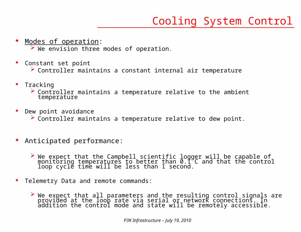
Modes of operation: We envision three modes of operation.
Constant set point Controller maintains a constant internal air temperature
Tracking Controller maintains a temperature relative to the ambient temperature
Dew point avoidance Controller maintains a temperature relative to dew point.
Anticipated performance:
We expect that the Campbell scientific logger will be capable of monitoring temperatures to better than 0.1 C and that the control loop cycle time will be less than 1 second.
Telemetry Data and remote commands:
We expect that all parameters and the resulting control signals are provided at the loop rate via serial or network connections. In addition the control mode and state will be remotely accessible.
Cooling System Control
P3K Infrastructure – July 19, 2010
Rack 1 Rack 2 Rack 3
Chiller
IN
out
Page 1
Chiller control #1Sunday, July 18, 2010
Cass Cage
Coude RoomChiller power
Contactor
Chiller contactor control
Controll room or AO Lab
Estop
Estop
Controller
Estop
By pass
Rack Main Power
contactor
Block Diagram
The Block Diagram is simplified to show the locations of the main components.
Items to note:
Main Power contactors for Cassegrain electronics and Chiller are controller by hardwire to contactors that do not depend on control electronics
Chiller fault and Estop signal to use existing telescope patch panels
Cooling System Control

P3K Infrastructure – July 19, 2010
Plumbing/Electric to Cass - Drag Line Option
J.Zolkower 27
P3K Cooling / Electric Drag Line Weight and Moment
Qty lbs / ft Total lbs / ft1" Liq cooling hose 2 0.9 1.8coolant 2 0.34 0.68Electric cable 1 0.57 0.57Cryo-Tiger gas line 2 0.3 0.6
Total lbs / ft 3.65
Assume vertical lift of hose onlyNo Diagonal or drag
Dec or RA angle (X)
Value H(ft)
Hose/cable lifted
(ft)
Weight Hose/cable
Lifted
Moment arm (ft)
Moment ft-lbs
15 1.88 9.88 36.05 7.25 26130 7.00 15.00 54.75 14.00 76745 14.00 22.00 80.30 19.80 159060 21.00 29.00 105.85 24.25 256775 26.12 34.12 124.55 27.05 3369
Dec bearing Pre-Load 5700 ft-lbs (south)RA Bearing Pre-load 3500 ft-lbs (east)
Dec Axis to Cage bottom 28'Hose exit to dome floor 8'Change in hgt due to Dec or RA rotation H
H = 28 (sin X)2
Risk of adverse effects on pointing and balance.Decision made to pursue a fixed plumbing arrangement; a.k.a. Auxiliary Wrap-up
Evaluation of using a drag line to bring coolant and electric to Cass
2x Cooling Lines1x Electric Cable2x Cryotiger lines?

P3K Infrastructure – July 19, 2010
Auxiliary Wrap-up Routing
J.Zolkower 28
Turning GuideAttached at yoke bottom center
South Polar Axis Routing
To Coude

P3K Infrastructure – July 19, 2010J.Zolkower 29
Auxiliary Wrap-up Routing
Dec AxisEast ArmTube

P3K Infrastructure – July 19, 2010
East Arm
Spool Attached To Tube (Tube not shown)
Guide trough (cutaway) Attached to East Arm
Dec Axis Wrap-up Concept
Dec axis
Igus Cable Carrier

P3K Infrastructure – July 19, 2010
Cass Plumbing & Electric Routing
Cooling distribution manifold
Electric Load Center
South side

P3K Infrastructure – July 19, 2010Southwest side
Cass Plumbing & Electric Routing
Liquid cooled rack locations

P3K Infrastructure – July 19, 2010
Pressure Drop of Coolant Plumbing
Compared flow velocity of main supply/return lines with 1” and 1 ¼ “ dia plumbing. At 16 gpm 1”→ 6.5 ft/sec; 1 ¼” → 4.2 ft/sec
Calculate viscosity of 35% Propylene Glycol / water mix at -13ºC (lowest coolant temp) 5.67 cSt , Using blended viscosity equation
Calculate Reynolds Number: for 1 ¼ Re= 7120→ Turbulent flow
Using D’Archy-Weibach eq., Calc pressure drop for 100 ft of pipe 1” pipe dP = 10.5 psi / 100ft 1 ¼ “ pipe dP = 3.5 psi / 100ft → 30% less than 1” pipe
Repeat process for ½” Cass Cage plumbing
J.Zolkower 33
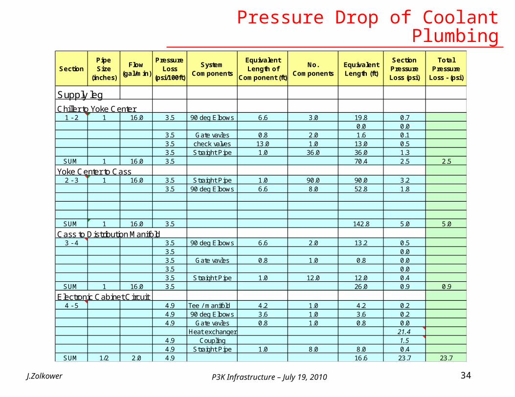
P3K Infrastructure – July 19, 2010J.Zolkower 34
Section Pipe Size
(inches)
Flow (gal/min)
Pressure Loss
(psi/100ft)
System Components
Equivalent Length of
Component (ft)
No. Components
Equivalent Length (ft)
Section Pressure Loss (psi)
Total Pressure
Loss - (psi)
Supply leg
Chiller to Yoke Center1 - 2 1 16.0 3.5 90 deg Elbows 6.6 3.0 19.8 0.7
0.0 0.03.5 Gate vavles 0.8 2.0 1.6 0.13.5 check valves 13.0 1.0 13.0 0.53.5 Straight Pipe 1.0 36.0 36.0 1.3
SUM 1 16.0 3.5 70.4 2.5 2.5
Yoke Center to Cass 2 - 3 1 16.0 3.5 Straight Pipe 1.0 90.0 90.0 3.2
3.5 90 deg Elbows 6.6 8.0 52.8 1.8
SUM 1 16.0 3.5 142.8 5.0 5.0
Cass to Distribution Manifold3 - 4 3.5 90 deg Elbows 6.6 2.0 13.2 0.5
3.5 0.03.5 Gate vavles 0.8 1.0 0.8 0.03.5 0.03.5 Straight Pipe 1.0 12.0 12.0 0.4
SUM 1 16.0 3.5 26.0 0.9 0.9
Electronic Cabinet Circuit4 - 5 4.9 Tee / manifold 4.2 1.0 4.2 0.2
4.9 90 deg Elbows 3.6 1.0 3.6 0.24.9 Gate vavles 0.8 1.0 0.8 0.0
Heat exchanger 21.44.9 Coupling 1.54.9 Straight Pipe 1.0 8.0 8.0 0.4
SUM 1/2 2.0 4.9 16.6 23.7 23.7
Pressure Drop of Coolant Plumbing
P3K Infrastructure – July 19, 2010J.Zolkower 35
Section Pipe Size
(inches)
Flow (gal/min)
Pressure Loss
(psi/100ft)
System Components
Equivalent Length of
Component (ft)
No. Components
Equivalent Length (ft)
Section Pressure Loss (psi)
Total Pressure
Loss - (psi)
Return leg2 - 1 1 16.0 3.5 90 deg Elbows 6.6 3.0 19.8 0.7
0.0 0.03.5 Gate vavles 0.8 2.0 1.6 0.13.5 check valves 13.0 1.0 13.0 0.53.5 Straight Pipe 1.0 36.0 36.0 1.3
SUM 1 3.5 70.4 2.5 2.5
3 - 2 1 16.0 3.5 Straight Pipe 1.0 90.0 90.0 3.23.5 90 deg Elbows 6.6 8.0 52.8 1.8
SUM 1 16.0 3.5 142.8 5.0 5.0
4 - 3 90 deg Elbows 6.6 2.0 13.2
Gate vavles 0.8 1.0 0.8
Straight Pipe 1.0 12.0 12.0SUM 1 16.0 3.5 26.0 0.9 0.9
5 - 4 2.0 4.9 Tee / manifold 4.2 1.0 4.2 0.24.9 90 deg Elbows 3.6 1.0 3.6 0.24.9 Gate valves 0.8 1.0 0.8 0.04.9 Coupling 1.54.9 Straight Pipe 1.0 8.0 8.0 0.4
SUM 4 1/2 2.0 4.9 16.6 2.3 2.3
Total SUM 32.1
Pressure Drop of Coolant Plumbing
P3K Infrastructure – July 19, 2010J.Zolkower 36
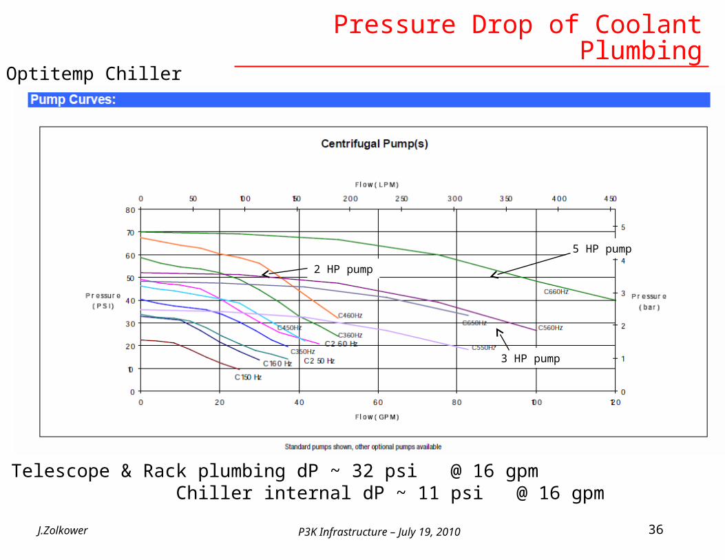
5 HP pump
3 HP pump
Telescope & Rack plumbing dP ~ 32 psi @ 16 gpm Chiller internal dP ~ 11 psi @ 16 gpm
2 HP pump
Pressure Drop of Coolant PlumbingOptitemp Chiller

P3K Infrastructure – July 19, 2010
DM Rack Cooling System Layout
J.Zolkower 37
Cage inside Cage outboard inside

P3K Infrastructure – July 19, 2010
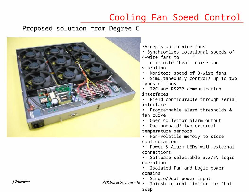
Cooling system operating strategy requires constant speed fan control of the each 9-fan tray
Xinetics DM drivers control fan speed by a stepped function based on temperature
We do not have access to the Xinetics software required to control fan speed
An alternate fan speed control system is required to operate the fans according to our cooling system strategy
J.Zolkower 38
Cooling Fan Speed Control
P3K Infrastructure – July 19, 2010
Cooling Fan Speed Control
J.Zolkower 39
Proposed solution from Degree C
•Accepts up to nine fans•·Synchronizes rotational speeds of 4-wire fans to eliminate “beat” noise and vibration•· Monitors speed of 3-wire fans•· Simultaneously controls up to two types of fans•· I2C and RS232 communication interfaces•· Field configurable through serial interface•· Programmable alarm thresholds & fan curve•· Open collector alarm output•· One onboard/ two external temperature sensors•· Non-volatile memory to store configuration•· Power & Alarm LEDs with external connections•· Software selectable 3.3/5V logic operation•· Isolated Fan and Logic power domains•· Single/Dual power input•· Inrush current limiter for “hot swap”•· Fan failure detection and prediction