Embed Size (px)
Citation preview

1
Manual de instalación/
Installation guide
P2S Series
plug&single-phase
P2S powered by

2
Versión 4.6
June 2018
Epic Power Converters S.L.

3
Contenido del manual
1. DESCRIPCIÓN GENERAL DEL P2S ................... 5
2. DESCRIPCIÓN EXTERIOR DEL P2S .................. 6
2.1. Convertidor DC/DC ..................................................... 8
2.2. Cargador de baterías ................................................. 15
2.3. Inversor monofásico ................................................. 16
2.4. Baterías .................................................................... 18 2.4.1. Baterías SMALL..................................................... 18 2.4.2. Baterías Medium .................................................. 19
2.5. Cableado suministrado ............................................. 20
2.6. Accesorios extra ........................................................ 24 2.6.1. Controlador de carga solar ................................... 24 2.6.2. Soporte cargador y ondulador ............................. 26 2.6.3. Armario completo precableado ........................... 27 2.6.4. Capacidad de bus ................................................. 28 2.6.5. Filtro DC ............................................................... 28 2.6.6. Módulo interfaz CAN ............................................ 29
3. INSTALACIÓN DEL P2S ................................ 31
3.1. Condiciones previas a la instalación .......................... 31
3.2. Herramienta necesaria .............................................. 32
3.3. Instalación ................................................................ 33
3.4. Puesta en marcha del Sistema P2S ............................ 42 3.4.1. Antes de conectar ................................................ 42 3.4.2. Proceso de conexión: IMPORTANTE .................... 42
3.5. Ajuste de la potencia máxima consumida por el motor. IMPORTANTE ........................................................................ 44
3.5.1. Valores orientativos de velocidad máxima de cabina 46 3.5.2. ¿Qué ocurre si no se ajusta correctamente el consumo máximo?................................................................. 47
3.6. Otras conexiones ...................................................... 47
4. OPERACIONES DE MANTENIMIENTO .......... 49
4.1. Mantenimiento del ascensor .................................... 49
4.2. Mantenimiento del P2S ............................................ 50
5. PRECAUCIONES .......................................... 51
Content of the guide
1. P2S GENERAL DESCRIPTION ................... 5
2. P2S EXTERNAL DESCRIPTION .................. 6
2.1. DC/DC Converter ................................................ 8
2.2. Battery charger ................................................. 15
2.3. Single-phase inverter ........................................ 16
2.4. Batteries ........................................................... 18 2.4.1. SMALL Batteries ......................................... 18 2.4.2. Medium Batteries ....................................... 19
2.5. Cables provided with the system ...................... 20
2.6. Optional accessories ......................................... 24 2.6.1. Solar charge controller or MPPT ................ 24 2.6.2. Holder tray ................................................. 26 2.6.3. Electrical cabinet prewired ......................... 27 2.6.4. Bus capacity ................................................ 28 2.6.5. DC Filter ...................................................... 28 2.6.6. CAN Interface Module ................................ 29
3. P2S INSTALLATION PROCEDURE ........... 31
3.1. Prerequisites to be met before the installation . 31
3.2. Neccesary tool .................................................. 32
3.3. Installation ....................................................... 33
3.4. P2S System Start Up ......................................... 42 3.4.1. Before connecting ...................................... 42 3.4.2. Connection procedure: IMPORTANT .......... 42
3.5. Maximum consumed power adjustment. IMPORTANT .................................................................. 44
3.5.1. Maximum cabin speed guide values .......... 46 3.5.2. What if maximum power consumption isn’t well fitted? ................................................................... 47
3.6. Other connections ............................................ 47
4. MAINTENANCE .................................... 49
4.1. Elevator maintenance ....................................... 49
4.2. P2S maintenance .............................................. 50
5. PRECAUTIONS ...................................... 51

4
6. DATOS TÉCNICOS, DIMENSIONES Y PESOS/ TECHNICAL DATA, DIMENSIONS AND WEIGHTS 52
6.1. Características técnicas del convertidor DC/DC/ DC/DC converter technical characteristics ........................................ 52
6.2. Características técnicas del cargador de baterías/ Battery charger technical characteristics ............................... 52
6.3. Características técnicas del inversor monofásico/ Single phase inverter characteristics ................................................ 53
6.4. Características técnicas del módulo de baterías/ Battery rack technical characteristics .................................... 53
6.5. Dimensiones del Convertidor DC/DC/ ....................... 54
6.6. Dimensiones del cargador de baterías ...................... 56
6.7. Dimensiones del inversor monofásico ....................... 57
6.8. Dimensiones del Controlador de carga solar ............. 59
6.9. Dimensiones del módulo de baterías ........................ 60 6.9.1. Bastidor baterías Small 2x2 .................................. 60 6.9.2. Bastidor baterías Small 4x1 .................................. 61 6.9.3. Bastidor baterías Medium .................................... 62
6.10. Dimensiones del soporte cargador y ondulador ........ 63
6.11. Dimensiones del armario completo precableado ...... 64
7. REGLAMENTACIÓN Y NORMATIVA ............... 65
6. DATOS TÉCNICOS, DIMENSIONES Y PESOS/ TECHNICAL DATA, DIMENSIONS AND WEIGHTS .................................................... 52
6.1. Características técnicas del convertidor DC/DC/ DC/DC converter technical characteristics ..................... 52
6.2. Características técnicas del cargador de baterías/ Battery charger technical characteristics ....................... 52
6.3. Características técnicas del inversor monofásico/ Single phase inverter characteristics ............................. 53
6.4. Características técnicas del módulo de baterías/ Battery rack technical characteristics ............................ 53
6.5. DC/DC converter dimensions ............................ 54
6.6. Battery charger dimensions .............................. 56
6.7. Single-phase inverter dimensions ..................... 57
6.8. Solar charge controller dimensions ................... 59
6.9. Batteries rack dimensions ................................. 60 6.9.1. Small batteries rack 2x2 ............................. 60 6.9.2. Small batteries rack 4x1 ............................. 61 6.9.3. Medium batteries rack ............................... 62
6.10. Holder tray dimensions .................................... 63
6.11. Electrical cabinet prewired dimensions ............. 64
7. REGULATIONS ......................................... 65
5
1. DESCRIPCIÓN GENERAL DEL P2S
El sistema plug&single-phase, P2S, es un equipo
que permite alimentar completamente un
ascensor de manera monofásica, con un
consumo máximo de red de 500W y que, en
caso de caída de red, podrá realizar hasta
aproximadamente un centenar de viajes, no
siendo necesarias, por tanto, las UPS
convencionales
Puede utilizarse tanto para nuevas instalaciones
como en ascensores ya en funcionamiento que
dispongan de variador de velocidad trifásico
(entrada de alimentación 400Vac), siendo su
mantenimiento muy sencillo.
A nivel técnico, el funcionamiento del P2S está
basado en la carga de las baterías por dos
medios: uno, a través de un cargador de red de
muy baja potencia máxima (500W) y dos,
almacenando aquella energía que se produce
cuando el motor del ascensor trabaja como
generador, es decir, cuando en vez de consumir
energía de la red, la genera. En los ascensores
convencionales, esta energía se pierde en forma
de energía calorífica en la resistencia de frenado
(no obstante, el P2S no sustituye a este elemento
de seguridad en ningún caso).
Por tanto, el sistema consigue un doble ahorro,
por un lado, el producido por reducir la energía
utilizada por el ascensor en hasta un 55%, por
recuperar la energía generada, y por otro el de
poder reducir el término de potencia contratada,
que en muchos casos es lo que mayor coste
acarrea en la factura de la luz.
Para conseguir un ascensor 100% sostenible
durante las horas de luz, el P2S también permite
el conexionado de placas solares
1. P2S GENERAL DESCRIPTION
Plug & single-phase system, P2S, is an electronic
device that can supply an elevator from single-
phase mains. The maximum power
consumption from the mains is 500W.
Furthermore, it permits one hundred elevator
trips in cases of energy power failure, making the
addition of a conventional UPS unnecessary.
It can be used both in new constructions and in
existing elevators (as long as they have a VVVF
elevator Drive of 400Vac input), with very simple
maintenance.
P2S performance is based on charging a battery in
two different ways. Firstly, a charger with very low
peak power (500W) withdraws energy from the
electricity supply. Secondly, by storing the energy
the elevator engine generates when the motor is
braking. In conventional elevators, this energy is
dissipated as heat in the brake resistors. However,
under no circumstances does P2S replace this
security device.
This can result in savings in two different ways.
Firstly, there is up to 55% energy savings from the
traction (reusing braking energy). Secondly, the
peak power contracted can be reduced
significantly (which usually implies lower contract
costs, although this depends on the installation
country).
To achieve a fully self-sufficient and sustainable
elevator during daylight, P2S system also allows
for the connection of solar panels.

6
2. DESCRIPCIÓN EXTERIOR DEL P2S 2. P2S EXTERNAL DESCRIPTION
El sistema P2S se compone de:
- Convertidor DC/DC – EPCLL-XXX-XXX
- Cargador de baterías – HEP 600C
- Inversor monofásico (400W o 700W)
- Baterías (diferentes referencias)
- Kit cableado (depende de las baterías
escogidas, la diferencia reside en la longitud
de los cables).
Dentro del sistema P2S, se dispone de diferentes
tamaños de convertidor DC/DC para satisfacer
las distintas necesidades del usuario:
- Convertidor DC/DC Potencia
[kW]
- EPCL-3k5-648 3,5
- EPCL-5k5-648 5,5
EPCL-7k-648 (2 x EPCL-3k5-
648 paralelizado) 7
EPCL-11k-648 (2 x EPCL-5k5-
648 paralelizado) 11
EPCL-Xk-648
(A través de paralelizados de
diferentes equipos se puede
alcanzar la potencia
necesaria)
X
Tabla 1. Potencia nominal convertidores DC/DC.
P2S system consists of:
- DC/DC Converter – EPCLL-XXX-XXX
- Battery charger – HEP 600C
- Single-Phase inverter (400W or 700W)
- Batteries (several references)
- Cable kit (depending on the batteries, the
difference is the cable length).
P2S system has two different sizes of DC/DC
converters to satisfy different requirements:
- DC/DC converter Power
[kW]
EPCL-3k5-648 3,5
EPCL-5k5-648 5,5
EPCL-7k-648 (2 x EPCL-3k5-
648 parallelized) 7
EPCL-11k-XXX (2 x EPCL-5k5-
648 parallelized) 11
EPCL-Xk-648
(It is possible to put as many
DC/DC converter as you
need in order to reach the
necessary power)
X
Table 1. Nominal power of DC/DC converters.
AC IN
SALIDAManiobra, luces...
SALIDA Variador velocidad
MonofásicoENTRADA
BATERÍAS
SOLAR INMPPT
CONEXIONES A MANIOBRA
AC OUT
Baterías
PV ENTRADA(opcional)
Fig. 1. Esquema del sistema P2S/ P2S system scheme.

7
La entrada de alimentación:
- 230Vac (máx. 500W).
La salida de alimentación del VVVF es:
- 600Vdc (3500W nominales para modelos
EPCL-3k5-XXX)
- 600Vdc (5500W nominales para modelos
EPCL-5k5-XXX)
- 600Vdc (7000W nominales para modelos
EPCL-7k-XXX)
- 600Vdc (11000W nominales para modelos
EPCL-11k-XXX)
Otros de elementos
- 230Vac (máx 400W o 700W opcional).
o Alimentación maniobra, frenos,
iluminación, etc.
Supply Input:
- 230Vac (max. 500W).
VVVF Supply Output:
- 600Vdc (nominal 3500W for EPCL-3k5-XXX
models)
- 600Vdc (nominal 5500W for EPCL-5k5-XXX
models)
- 600Vdc (nominal 7000W for EPCL-7k-XXX
models)
- 600Vdc (nominal 11000W for EPCL-11k-XXX
models)
Other elements:
- 230Vac (max 400W o 700W)
o Controller, brakes, lighting, etc.

8
2.1. Convertidor DC/DC
A continuación, se pueden ver las imágenes que
muestran los distintos conectores del modelo
EPCL 3k5 (Fig. 2) y del EPCL 5k5 (Fig. 3).
2.1. DC/DC Converter
The next two figures show external connections of
EPCL 3k5 model (Fig. 2) and EPCL 5k5 model (Fig.
3).
Fig. 2 Convertidor DC/DC 3k5/ 3k5 DC/DC Converter.
0
10
12
3
4
6
9
5
7
8

9
Fig. 3 Convertidor DC/DC 5k5/ 5k5 DC/DC Converter.
0
12
3
4
6
10
9
7
8
5

10
0) VENTILADORES: Importante dejar
despejadas las salidas y entradas de aire.
0) FANS: It is important to leave the fan outputs and
inputs unobstructed.
1) SALIDAS A LA MANIOBRA:
IMPORTANTE: Se tratan de contactos libres de
potencial. Las salidas no deben someterse a
tensiones superiores a 24V en continua o
250Vac, ni a corrientes superiores a 5A.
- 1A) COMÚN: Conexión común de los
terminales 1B, 1C, 1D, 1E y 1F.
- 1B) STATUS OK: (Normally Open) Con
circuito cerrado a común indica que el
convertidor DC/DC tiene habilitada la salida
de tensión al bus en el variador y por lo
tanto este se encuentra alimentado.
- 1C) LOW BATTERY 1 (Normally Close): Con
circuito abierto indica Estado de Carga de
baterías < 30%.
- 1D) LOW BATTERY 1 (Normally Open): Con
circuito cerrado a común indica Estado de
Carga de baterías < 30%.
- 1E) LOW BATTERY 2: (Normally Open) Con
circuito cerrado a común indica Estado de
Carga de baterías< 60%.
- 1F) AC CHARGER ON: (Normally Open) Con
circuito cerrado a común indica a la
maniobra que el cargador de red está
funcionando correctamente.
- 1G) DETECCIÓN DE DERIVA (Normally Open).
- 1H) No conectado.
El estado de los contactos en función del estado
de carga de las baterías (SoC) es el siguiente:
[cerrado=0, abierto=1]
1) OUTPUTS TO CONTROLLER:
IMPORTANT: These are potential-free contacts.
These outputs should never withstand voltages
higher than 24V DC or 250V AC. These outputs
should never conduct currents higher than 5A.
- 1A) COMMON: Common connection of
terminals 1B, 1C, 1D, 1E y 1F.
- 1B) STATUS OK: (Normally Open). When this
terminal is short-circuited to common it
indicates that the DC/DC converter is in
operation and therefore, it is supplying the DC
link of the drive, so the drive is energized.
- 1C) LOW BATTERY 1 (Normally Closed): When
this terminal is open, it indicates SOC < 30%.
- 1D) LOW BATTERY 1 (Normally Open): When
this terminal is short-circuited to common it
indicates SOC < 30%.
- 1E) LOW BATTERY 2 (Normally Open): When
this terminal is short-circuited to common it
indicates SOC < 60%.
- 1F) AC CHARGER ON: (Normally Open): When
this terminal is short-circuited to common it
indicates to the controller that the battery
charger is working properly.
- 1G) EARTH LEAKEAGE DETECTION (Normally
Open).
- 1H) No connect.
The condition of the contacts depending on the
State Of Charge (SOC) of the batteries is:
[closed=0, open=1]
0

11
MODO/
MODE
CONDICIÓN/
CONDITION
Estado del contacto
1C/ 1C contact state
Estado del contacto
1D/ 1D contact state
Estado del contacto
1E/ 1E contact state
Estado variador/
VVVF state
1 SoC >= 60% Cerrado/ close (0) Abierto/ open(1) Abierto/ open (1) ON
2 30% <= SoC <
60% Cerrado/ close (0) Abierto/ open (1) Cerrado/ close (0) ON
3 SoC < 30% 1 Abierto/ open (1) Cerrado/ close (0) Abierto/ open (1) ON
4 SoC <= 15% 2 Abierto (1) Cerrado (0) Cerrado (0) OFF
1No se debe comenzar un viaje de ascensor
estando en modo 3.
2 Cuando el equipo pasa a modo 4, el variador de
velocidad estará apagado.
1 A elevator trip must not be carried out in mode
3. 2 If mode 4 is active, the VVVF will be disconnected.
Tabla 2. Estado de carga según contactos/ State of charge depending on contacts.
2) CONTROL DE ELEMENTOS AUXILIARES:
- 2A) y 2B) RC INVERTER + y -: Deshabilita el
ondulador bajo petición de la maniobra a
través de la entrada ENABLE INV (3C). En
caso de apagar el DC/DC con el interruptor
“ON OFF”, el “Inversor monofásico” será
deshabilitado.
- 2C) y 2D) (Remote Control) RC CHARGER + y
-: Deshabilita el cargador de baterías
mediante cortocircuito entre 2C y 2D.
o Esta deshabilitación será realizada
automáticamente por el
Convertidor DC/DC en caso de
disponer del accesorio “Regulador
de Carga Solar” y de que exista
energía suficiente por parte de las
placas solares. En este caso el
consumo de red será nulo
2) OUTPUTS to AUXILIARY ELEMENTS:
- 2A) and 2B) RC INVERTER + and -: The inverter
can be disabled by controller requirement
using input ENABLE INV (3C). If the DC/DC
converter is turned off with the main switch,
the inverter will also be disabled.
- 2C) and 2D) (Remote Control) RC CHARGER +
and -: A short-circuit between terminals 2C
and 2D disables the battery charger.
o The DC/DC converter disables the
charger when the solar regulator is in
operation and if there is enough
solar energy from the solar panels (if
you have acquired this item). In this
particular case, the consumption
from mains would be zero.

12
3) ENTRADAS DESDE LA MANIOBRA:
- 3A) COMUN: Común para los circuitos de
ENABLE (3B y 3C).
- 3B) ENABLE DC/DC: Habilitación/
deshabilitación del Convertidor DC/DC. Para
alimentar el variador es necesario que la
maniobra realice un cortocircuito entre los
terminales 3A y 3B.
o La maniobra puede utilizar este
control para apagar el variador y
anular el consumo en reposo del
mismo. Después podrá ser
habilitado (alimentado) de manera
prácticamente inmediata por la
maniobra para el siguiente
trayecto.
o Esto puede llevar a un importante
ahorro energético del ascensor ya
que el stand-by del variador de
velocidad pasaría a ser cero
durante el reposo del ascensor.
- 3C) ENABLE INVERTER: Entrada que habilita
o deshabilita la alimentación completa del
equipo. En caso de dejar este terminal sin
conexión (circuito abierto), tanto el
Convertidor DC/DC (y por tanto también
variador de frecuencia) como el Inversor
monofásico permanecen deshabilitados.
Para alimentar el ascensor, es necesario
cortocircuitar de manera externa los
terminales 3A y 3C.
3) INPUTS from the CONTROLLER:
- 3A) COMMON: Common for the ENABLE
inputs (3B and 3C).
- 3B) ENABLE DC/DC: DC/DC Converter
enabling or disabling input. To provide energy
to the DC bus, it is mandatory for the
controller to short-circuit terminals 3A and 3B.
o The controller may use this option to
turn off the drive to avoid standby
consumption. Then, it would be fed
instantaneously by the controller for
the next trip.
o This feature could result in important
energy savings for the elevator
because the frequency controller
standby will be zero when the
elevator is stopped.
- 3C) ENABLE INVERTER: Input to enable or
disable the complete supply of the elevator. If
3C and 3A are in open circuit both DC/DC
converter and AC inverter are disabled and
there is NO supply being provided to any
element of the elevator. When terminal 3C is
short-circuited to 3A, both DC/DC converter
and inverter are enabled.
4) CONEXIÓN POTENCIA
- 4A) y 4B) BATTERY TO INVERTER + y BATTERY
TO INVERTER -: Conexión del inversor
monofásico a baterías a través de
Convertidor DC/DC.
- 4C) y 4D) AC+ CHARGER y AC- CHARGER:
Conexión del cargador de red a las baterías
a través de Convertidor DC/DC.
4) POWER CONNECTIONS
- 4A) and 4B) BATTERY TO INVERTER + and
BATTERY TO INVERTER -: Supplies the inverter
from the batteries, through the DC/DC
converter.
- 4C) and 4D) AC+ CHARGER and AC- CHARGER:
Battery charger to batteries, through DC/DC
converter.
Convertidor DC/DC
Maniobra
3A
3C
3B

13
- 4E) y 4F) PV+ CONTROLLER y PV-
CONTROLLER: Conexión de regulador de
carga solar a baterías a través de
Convertidor DC/DC. (Sólo necesario si
adquiere el Regulador de carga solar).
- 4E) and 4F) PV+ CONTROLLER and PV-
CONTROLLER: Solar charge controller to
batteries through DC/DC converter. (This is
only necessary if the solar charge controller
has been acquired).
5) “Inverter POWER”: Salida de alimentación del
variador. N (-), P (+).
5) “Inverter POWER”: Frequency controller output. N
(-), P (+).
6) CAN bus (opcional):
- Conexión a EPCL mediante interfaz.
6) CAN bus (optional):
- Connection to optional EPCL CAN interface.
7) y 8) CONEXIÓN A TIERRA: Puntos de conexión a
tierra para conectar los componentes
necesarios.
7) y 8) EARTH CONNECTION: Earthing connection
points to connect necessary components.
7 8

14
9) CONEXIÓN A BATERÍAS: A través del prensaestopas
por el cual entrará el cable que conecta las baterías
con el convertidor DC/DC. [Negro: terminal negativo,
Rojo: terminal positivo]. La conexión a baterías puede
depender de la referencia de convertidor DC/DC
utilizada. Principalmente existen dos versiones.
9) BATTERY CONNECTION: Through the clablegland
shown below the wires enter to connect the batteries
and the DC/DC converter. [Black: negative, Red:
positive]. The battery connection varies depending
on the type of the DC/DC converter used.
10) “ON OFF”: Interruptor de apagado/encendido del
Convertidor DC/DC.
- En posición OFF tanto la alimentación del variador
como la salida 230Vac del inversor monofásico
quedarán deshabilitadas independientemente de
las señales de ENABLE (conector 3A, 3B, 3C).
10) “ON OFF”: Main switch of DC/DC converter.
- In the OFF position, both the supply to the drive,
as well as the output of the 230V AC inverter will
be disabled independently of ENABLE signals (3A,
3B, 3C).
BARRA LED: Situada en un lateral del equipo: LED STICK: It is placed in the lateral side of the converter:
Una tira de leds en el lateral derecho del convertidor
DC/DC mostrará tanto la potencia suministrada como el
SOC del pack de baterías.
An LED stick placed on the lateral side of the DC/DC
converter will show the supplied power and the batteries
SOC.
10

15
- Cuando los leds se iluminan de abajo arriba y de
arriba abajo continuamente, el equipo está a la
espera de ser habilitado.
- Cuando los leds se iluminan de manera fija
muestran la potencia suministrada. (Esto ocurre
cuando el ascensor está en movimiento y el
convertidor DC/DC suministra la potencia).
- Cuando los leds se iluminan de modo pulsante
muestran el SOC de las baterías.
- The DC/DC converter is waiting to be enabled
when the LEDs blink from bottom to top and from
top to bottom.
- When LEDs are illuminated, they are showing the
supplied power. (This happens when elevator is
moving and the DC/DC converter is supplying
power).
- When LEDs are on pulsating mode, they are
showing the batteries’ SOC.
2.2. Cargador de baterías
2.2. Battery charger
11
12
13
14
15
16
17
18
19
20
21
SALIDA (DC)ENTRADA
(AC)
11) Conexión a tierra – (FG)
12) Conexión AC (Fase) – (AC/L)
13) Conexión AC (Neutro) – (AC/N)
14) Conexión con el terminal RC CHARGER + del
convertidor DC/DC– (RC+)
15) Conexión con el terminal RC CHARGER - del
convertidor DC/DC – (RC- & GND)
16) No conectar – (+5VSB)
17) Salida a borne Negativo de batería – (-V)
i) Mismo punto eléctrico que (18)
18) Salida a borne Negativo de batería – (-V)
i) Mismo punto eléctrico que (17)
19) Salida a borne Positivo de batería – (+V)
i) Mismo punto eléctrico que (20)
20) Salida a borne Positivo de batería – (+V)
i) Mismo punto eléctrico que (19)
21) LED indicador
11) Ground connection–(FG)
12) AC connection (Phase) – (AC/L)
13) AC connection (Neutral) – (AC/N)
14) Connection with RC CHARGER + of the DC/DC
converter– (RC+)
15) Connection with RC CHARGER – of the DC/DC
converter– (RC- & GND)
16) Do not connect – (+5VSB)
17) Battery negative terminal connection – (-V)
i) Same electric node as (18)
18) Battery negative terminal connection – (-V)
i) Same electric node as (17)
19) Battery positive terminal connection – (+V)
i) Same electric node as (20)
20) Battery positive terminal connection – (+V)
i) Same electric node as (19)
21) LED indicator
Fig. 4 Cargador de baterías/ Battery charger.

16
2.3. Inversor monofásico
Existen dos posibles inversores disponibles en función
de las necesidades.
2.3. Single-phase inverter
There are two different inverters available depending
on requeriments.
Cara delantera
Cara trasera
25
22
29
3026
27
23
24
28
Fig. 6 Inversor monofásico TS-700/ Single phase inverter TS-700.
22) Salida 230Vac: es el punto del cual deberá colgar la
alimentación monofásica del ascensor.
23) Diodo LED Status: verde.
24) Pulsador de Setting: permite cambiar la tensión de
salida entre 220Vac y 240Vac y la frecuencia entre
50Hz y 60Hz (por defecto la salida se establece en
230Vac y 50Hz).
25) Interruptor ON/OFF.
22) 230Vac Output: Supplies all single-phase elements of
the elevator.
23) LED diode Status: Green
24) Setting button: Allows switching of output voltage
between 220Vac and 240Vac, and switching of
frequency between 50Hz y 60Hz (default output set
at 230Vac and 50Hz).
25) ON/OFF Switch.
22
25
24
23
27
26
30
29
28
Fig. 5 Inversor monofásico TS-400/ Single phase inverter TS-400.

17
26) Ventilador.
27) Conector a tierra.
28) RC: Conectado a los terminales “RC inverter +” y “RC
inverter -”. Conectado al terminal 2A y 2B del
convertidor.
29) Entrada DC Positivo Batería.
30) Entrada DC Negativo Batería.
26) Fan.
27) Ground connection.
28) RC: Connected to terminals “RC inverter +” and “RC
inverter -” of the converter (terminals 2A and 2B).
29) Battery positive DC Input.
30) Battery negative DC Input.

18
2.4. Baterías
En función del recorrido máximo del ascensor y de la
carga nominal de la cabina, será conveniente instalar
un tipo de baterías u otro. Por ello, se disponen de
diferentes tipos de baterías, ordenadas por orden de
capacidad de almacenaje de energía: SMALL, MEDIUM
y LARGE. epic power se encargará de ofrecer el
asesoramiento necesario para la elección de las
baterías más adecuadas para cada instalación.
2.4.5. Baterías SMALL
2.4. Batteries
Different types of batteries are needed and should be
installed according to elevator features (elevator
travel and rated load). Thus, three battery sizes are
available: SMALL, MEDIUM and LARGE. epic power will
provide the necessary advice in order to select the
most suitable set of batteries in each elevator.
2.4.5. SMALL Batteries
Fig. 7 Bastidor de baterías Small, numeración de terminales, baterías y cableado de las mismas/ Small battery
rack, terminal numbering, batteries and connections.
31
32
100A Fuse
Batería 1Battery 1
Batería 4Battery 4
Batería 2Battery 2
Batería 3Battery 3
33
34
38
37
36
35
CABLE OEJ_S
CABLE OEH
9
40
39
CABLE OEI_S
CABLE OEM
19
2.4.2. Baterías Medium
2.4.2. Medium Batteries
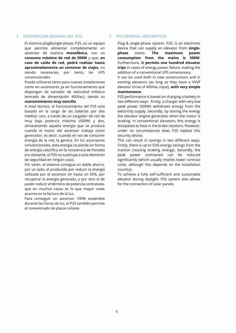
Fig. 8 Bastidor de baterías Medium, numeración de terminales, baterías y cableado de las mismas/ Medium
battery rack, terminal numbering, batteries and connections
31) Borne positivo de la batería 1
32) Borne negativo de la batería 1
33) Borne positivo de la batería 2
34) Borne negativo de la batería 2
35) Borne positivo de la batería 3
36) Borne negativo de la batería 3
37) Borne positivo de la batería 4
38) Borne negativo de la batería 4
39) Fusible con portafusibles (+)
40) Fusible con portafusibles (-)
31) Positive terminal of battery 1
32) Negative terminal battery 1
33) Positive terminal of battery 2
34) Negative terminal battery 2
35) Positive terminal of battery 3
36) Negative terminal battery 3
37) Positive terminal of battery 4
38) Negative terminal battery 4
39) Fuse and fuse-holder (+)
40) Fuse and fuse-holder (-)
Batería 4Battery 4
Batería 3Battery 3
Batería 2Battery 2
Batería 1Battery 1
37
3835
33
31
36
34
32
CABLE OEJ_M
39
CABLE OEH
9
CACA
40
CABLE OEM
CABLE OEI_M

20
2.5. Cableado suministrado
A continuación, se describen los cableados necesarios
para la instalación en el equipo.
- EPCL CABLE OEG: Alimentación del VVVF (Variador
de velocidad). Manguera de tres almas de 2.5mm2
de tres metros de longitud con terminales de
puntera en un extremo y conector aéreo para
en el otro con tierra libre en terminal de horquilla.
Conecta la salida “Inverter Power” del
Convertidor DC/DC con el variador de velocidad.
2.5. Cables provided with the system
Below, the necessary cables for P2S installation are
described.
- EPCL CABLE OEG: VVVF Supply (frequency
controller). Three 2.5mm2 cored, three meter-
long cable. Ferrule ports on one side, and aerial
connector for on the other side with free
earth and fork terminal.
Connects “Inverter Power” output at DC/DC
converter, to VVVF Drive.
Fig. 9 EPCL Cable OEG.
- EPCL CABLE OEA: Conexión de cargador de
baterías e inversor monofásico. Latiguillo de cuatro
conductos de 2.5mm2 de sección y 1m de longitud
con terminal aéreo en un extremo y terminales en
“U” en el otro.
Dos de los subcables conectan los terminales
“Battery to inverter +” y “Battery to inverter -”
del Convertidor DC/DC con los terminales
y del inversor monofásico.
Los otros dos subcables conectan los terminales
“AC+ charger” y “AC- charger” del
convertidor DC/DC con y del cargador de
baterías.
- EPCL CABLE OEA: Connection between batteries
and AC inverter. Twisted four-wire cable of
2.5mm2 and 1m in length. Aerial terminal on one
side and U connectors on the other side.
Two of the wires connect the terminals “Battery
to inverter +” and “Battery to inverter -”
from the DC/DC converter to terminals and
of the AC inverter.
The other two wires connect the terminals “AC+
charger” and “AC- charger” of the DC/DC
converter to the terminals and of the
battery charger.
5
5
5
5
18 19
4D
D
4C
30
29 4B
4A
18 19
4D
D
4C
30
29
4A 4A

21
Fig. 10 EPCL Cable OEA.
- EPCL CABLE OEH: Conecta las baterías con el
convertidor DC/DC. Cable trenzado de dos almas
de 25mm2 y 2 metros de longitud con terminales
cerrados en ambos extremos. En el caso del EPCL
3k5 este cable conecta con el equipo mediante
prensaestopas (sección 25mm2), pero en el EPCL
5k5, la conexión se realiza mediante conector
aéreo (sección 50mm2).
Conecta el terminal del Convertidor DC/DC con
los terminales y de protección de baterías.
- EPCL CABLE OEH: Connects batteries to DC/DC
converter. Two 25mm2 cored, 2-meter-long
twisted wire. Closed ports on both sides.
Connects DC/DC converter terminal to
terminal and of the batteries array
protection.This cable is connected to the EPCL
3k5 trough a clablegland (25mm2 section), but in
the EPCL 5k5, the connection is through aerial
connector (50 mm2 section).
Fig. 11 EPCL Cable OEH.
- EPCL CABLE OEJ_S ó OEJ_M: (3 unidades). Conecta
baterías entre sí dos a dos. Cable de 25mm2.
+ 23 cm longitud para small (OEJ_S)
+ 47 cm longitud para médium (OEJ_M)
Ambos con terminal cerrado en los dos extremos,
cuya métrica es M5 para small y M6 para médium.
Conecta el terminal negativo de la batería 1, 2 y 3 (
, y ) con el terminal positivo de la
batería 2, 3 y 4, respectivamente ( , y ).
Ver Fig. 7 o Fig. 8.
- EPCL CABLE OEJ_S ó OEJ_M: (3 units). Connects
pairs of batteries. 25mm2 cable.
+ 23 cm long for small (OEJ_S)
+ 47 cm long for medium
Closed port on both sides with M5 metric for
small and M6 for medium.
Connects negative terminal at battery 1, 2 and 3 (
, and ) to positive terminal at battery 2,
3 and 4, respectively ( , and ). See Fig.
7 o Fig. 8.
38 31
9
38 31
9
37 35 33
36 34 32
37 35 33
36 34 32

22
Fig. 12 EPCL Cable OEJ_S.
- EPCL CABLE OEC (opcional): Latiguillo de dos
conductos de 2.5mm2 de sección y 1 m de longitud.
Conecta el Controlador de carga solar con el
Convertidor DC/DC.
Conecta el terminal y del Convertidor
DC/DC con el regulador de carga solar.
- EPCL CABLE OEC (optional): Twisted pair, two
wires. 2.5mm2 core and 1 m length. Connects the
solar charge controller (MPPT) with the DC/DC
converter.
Connection of terminals and of the DC,
DC converter to the solar charge controller.
Fig. 13 EPCL Cable OEC (opcional/optional).
- EPCL CABLE OEI_S + EPCL CABLE OEM_S ó OEI_M +
EPCL CABLE OEM_M + PORTA-FUSIBLE BIPOLAR +
FUSIBLES: Cables de 25mm2.
+ OEI_S: 30 cm de longitud para baterías small
+ OEI_M: 1 m de longitud para baterías médium
+ OEM_S: 30 cm de longitud para baterías small
+ OEM_M: 55 cm longitud para baterías médium
Ambos conectados a un portafusibles doble.
+ CABLE OEI conecta el terminal positivo de la
batería 1 ( ) con el alma roja del CABLE OEH (
), es decir, interta un fusible entre rl
convertidor DC/DC y las baterías.
+ CABLE OEM conecta el terminal negativo de la
batería 4 ( ) con el alma negra del CABLE OEH
( ),es decir, interta un segundo fusible entre
el convertidor DC/DC y las baterías.
- EPCL CABLE OEI_S + EPCL CABLE OEM_S ó OEI_M
+ EPCL CABLE OEM_M + DOUBLE POLE FUSE
HOLDER + FUSE: 25mm2 cables.
+ OEI_S: 30 cm length wire for small batteries
+ OEI_M: 1 m length for medium batteries
+ OEM_S: 30 cm length wire for small batteries
+ OEM_M: 55 cm length for medium batteries
Each connect to a two pole fuse holder.
+ CABLE OEI connects the positive terminal of
battery 1 ( ) to positive terminal at red core in
CABLE OEH ( ). In other words, it inserts a fuse
between the batteries and the DC/DC converter.
+ CABLE OEM connects the negative terminal of
battery 4 ( ) to negative terminal at black core
in CABLE OEH ( ). In other words, it inserts a
second fuse between the batteries and the
DC/DC converter.
4F 4E 4F 4E
40
38
39
31
40
38
39
31
23
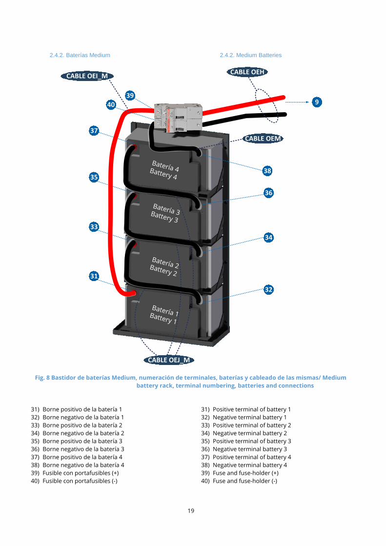
Fig. 14 EPCL Cable OEI_S + EPCL Cable OEM_S + porta-fusible bipolar + fusibles/ EPCL Cable OEI_M + EPCL Cable
OEM_M + double pole fuse holder + fuses.
- EPCL CABLE OEB: Cable de cuatro vías acabado en
terminal aéreo en un extremo y conector macho
para PCB (2 vías) y terminal en U (otras dos vías).
Tiene una longitud de 1 metro.
Conecta los terminales RC INVERTER + ( ), RC
INVERTER - ( ), RC CHARGER + ( ) y RC
CHARGER - ( ) del convertidor DC/DC con el
conector del inversor monofásico y los
terminales y del cargador de baterías.
- EPCL CABLE OEB: Four wire cable terminating in
an aerial connector on one side and male
PCBconnector on the other (two wires) and 2 U
terminals. 1m in length.
Connects terminals RC INVERTER + ( ), RC
INVERTER - ( ), RC CHARGER + ( ) y RC
CHARGER - ( ) of the DC/DC Converter to the
connector of the single-phase inverter and
terminals and of the battery charger.
Fig. 15 EPCL Cable OEB.
31
3839
40
CABLE OEI_S
CABLE OEM_S
15 14
28
2D
2C 2B
2A
15 14
28
2D
2C 2B
2A

24
2.6. Accesorios extra
2.6.1. Regulador de carga solar
2.6. Optional accessories
2.6.1. Solar regulator
Fig. 16 Regulador de carga solar/ Solar regulator (1).
Para utilizar energía solar se puede incorporar al
sistema un regulador de carga solar
que permite conectar paneles fotovoltaicos. Tiene las
siguientes características:
To charge the batteries with solar energy, a solar
charger or solar panel regulator is included as an
option. The solar charger has the following technical
features.
Características/ Features Valor/ Value
Referencia/ Reference MPPT 150/35
Corriente máxima de batería/ Maximum battery current 35A
Corriente máxima carga admisible/ Maximum charge
current 16.25 A
Voltaje máximo circuito abierto FV/ Maximum open circuit
voltage PV 150V
Eficiencia máxima/ Maximum efficiency 98%
Temperatura trabajo/ Working temperature -30 ÷60ºC (Hasta 40 ºC para
potencia nominal)
Peso/ Weight 1,25 Kg
IMPORTANTE: La tensión FV debe exceder en 5V la
tensión de la batería (Vbat) para que arranque el
controlador. Una vez arrancado, la tensión FV
mínima será de Vbat + 1V.
Este dispositivo se conectará al convertidor DC/DC y a
las placas solares. Dadas las características de las
baterías, la potencia eléctrica máxima que deben
suministrar las placas solares es de 800 W. Es muy
IMPORTANT NOTE: FV voltage must exceed the
voltage of the battery by 5V (Vbat) for the
controller to be started. Once in operation, the
minimum FV voltage should be Vbat + 1V.
This device is connected to the DC/DC converter and
to the solar panels. Taking into consideration the
bettery specifications, the maximum solar power that
can be installed is 800 W. It is very important to revise

25
importante que se revisen las características técnicas
de la placa solar para estudiar su compatibilidad antes
de conectarlas. Por ejemplo, con unas placas
solares cuya corriente de cortocircuito es de 8.1A y
tensión en el punto de máxima potencia es de 36V, se
deben poner dos placas conectadas en serie.
the solar panel features to make sure they are
compatible with this solar regulator. As an example,
for solar panels of short-circuit current of 8.1A and
36V at maximum power, two panels have to be
connected in series to match the regulator
requirements.
Fig. 17 Regulador de carga solar/ Solar charger controller (2).
41) “BATTERY +”: Conectado al punto del Convertidor
DC/DC mediante el cable rojo del CABLE OEC.
42) “BATTERY -”: Conectado a al punto del Convertidor
DC/DC mediante el cable negro del CABLE OEC.
43) “PV -”: Conexión a las placas solares.
44) “PV +”: Conexión a las placas solares.
45) Conexión a GND.
41) “BATTERY +”: Connected to terminal of the
DC/DC converter with the red wire of CABLE OEC.
42) “BATTERY -”: Connected to terminal of the DC/DC
converter with the black wire of CABLE OEC.
43) “PV -”: Connection to solar panels.
44) “PV +”: Connection to solar panels.
45) Connection to GND.
41 42 43 44
45
4F
4E
4F
4E

26
2.6.2. Soporte cargador y ondulador
Para mayor facilidad a la hora de realizar la instalación
y el cableado entre los distintos elementos, se puede
adquirir a modo opcional una plancha metálica donde
tanto el ondulador como el cargador de baterías, estén
ya colocados y cableados.
GA R A N T I C E L A C O N EX I Ó N A T I E R R A D E L A B A N D EJ A .
2.6.2. Holder tray
A metallic plate can be purchased optionally for
greater ease when installing and wiring the multiple
components. In this case the battery charger and the
inverter are already installed and pre-wired.
EN S U R E S H O L D E R T R A Y G R O U N D C O N N E C T I O N .
Fig. 18 Soporte Cargador Ondulador/ Holder tray (charger and inverter)
Si ha adquirido este equipo con este complemento no
tendrá que realizar algunos de los pasos de la
instalación, tal y como se indica en el apartado 3.
You can skip some installation steps as shown in
chapter 3 if you have acquired this item.

27
2.6.3. Armario completo precableado
Para mayor facilidad a la hora de realizar la instalación
y el cableado entre los distintos elementos, se puede
adquirir a modo opcional un armario con todos los
elementos del sistema precableados entre ellos, a
excEPCLión de las baterías.
Esta solución dispone de su propio manual de
instalación.
2.6.3. Prewired electrical cabinet
A metallic cabinet can be purchased optionally for
greater ease when installing and wiring the multiple
components. In this case all the necessary elements
are already installed and pre-wired, with the
exception of the batteries
Another installation guide is available for this specific
option.
Fig. 19 Armario completo precableado/ Prewired electrical cabinet.

28
2.6.4. Capacidad de bus
Según el variador de frecuencia utilizado se hará
necesario adquirir este accesorio para aumentar la
capacidad de bus intrínseca de éste. Consultar con epic
power sobre los variadores afectados.
Para el correcto funcionamiento del convertidor DC/DC
(EPCLL) es necesario que la capacidad interna del bus
de continua del variador sea al menos de 400 uF.
2.6.4. Bus capacity
Depending on your frequency controller, it may be
necessary to acquire this item to increase the bus
capacity of the controller. It is convenient to consult
epic power about affected frequency controllers.
For the correct operation of the DC/DC converter, the
internal capacity of the DC bus has to be greater than
400 uF.
Fig. 20 Capacidad extra de bus DC y conexionado/ Extra DC bus capacity and connection.
Servido con cables de 60 cm de longitud y preparado
para colocar en carril DIN, únicamente precisa conexión
al terminal positivo (cable rojo) y negativo (cable negro)
del bus de continua del variador.
Delivered with 60cm-long cables ready to be placed
on a DIN rail, only requires connection to the positive
terminal (red cable) and negative (black cable) of the
DC bus of the frequency controller.
2.6.5. Filtro DC
Este filtro podría ser necesario en caso de que el motor
estuviera colocado a más de 10 metros del variador de
velocidad y/o que el cable entre ellos no estuviera
apantallado.
2.6.5. DC Filter
This filter may be necessary if the engine is placed
more than 10 metres away from the frequency
controller and/or the connection cable between them
is not shielded.
Fig. 21 Filtro DC y conexionado/ DC filter and connection.
DC / ACAC / DC Rb
rake
Cbus
L 1/R
L 2/S
L 3/T
VVFVariable Frequency Drive
DB P1 P(+
)
N(-
)
U V W
Cap Bus
DC / ACAC / DC Rb
rake
Cbus
L 1/R
L 2/S
L 3/T
VVFVariable Frequency Drive
DB P1 P(+
)
N(-
)
U V W
Filtro DC cerca del variador

29
La conexión de este accesorio se realizará en serie
entre la conexión al variador (P+, N- y tierra) y el
convertidor tal y como se representa en la Fig. 21. El
filtro DC deberá colocarse lo más cerca posible del
variador. Es filtro DC irá marcado para indicar la
posición que queda en el lado del VVVF (variador de
frecuencia).
This item’s connection will be made in series between
the frequency controller connection (P+, N- and
ground) and the converter as shown in Fig. 21. The DC
filter should be placed as close as possible to the
frequency controller and it will be labelled to indicate
the correct position.
2.6.6. Módulo interfaz CAN
Si se requiere comunicación CAN, hay un módulo
disponible para ello. Antes de la instalación, se debe
asegurar que el convertidor está desconectado, el
interruptor principal en posición OFF, los portafusibles
abiertos y el conector desconectado. Los
siguientes pasos los debe llevar a cabo personal
cualificado:
- Instalación
El conector de 8 vías de la imagen de la izquierda debe
ser conectado al conector del EPC (solo acepta una
posición). Después de conectar el módulo, se debe
atornillar con un tornillo de métrica M3 en el agujero
especificado en la imagen inferior derecha.
2.6.6. CAN interface module
If CAN communication is required, a CAN interface
module is available. Before the installation, make sure
that the EPC is disconnected, the main switch should
be switched off, the fuse holders opened and
connector disconnected. The following steps should
be carried out by qualified personnel:
- Installation
The 8-way connector in the left hand picture shown
below should be connected to connector of the
EPC (only one position is possible). After connecting
the module, it should be attached using a M3 screw in
the hole in the right hand picture below.
Fig. 22 Conexionado módulo CAN al convertidor/ CAN module connection to DC/DC converter.
- Cableado
El módulo CAN ya está preparado para iniciar la
comunicación, aunque es necesario mencionar que el
conector de la izquierda de la imagen inferior está
reservado y el de la derecha es el que debe usarse
para la comunicación.
CONECTOR 7. CAN 1
- 7A) GND
- 7B) CAN Low
- 7C) CAN High
- 7D) Salida 5V 0.1A
- Wiring
Now, the module is ready for CAN communication. It
is necessary to mention that the connector on
the left is reserved and the one on the right is
free for communication.
CONNECTOR 7. CAN 1
- 7A) GND
- 7B) CAN Low
- 7C) CAN High
- 7D) 5V 0.1A Out
6
5
6
5
8
7 8
7

30
CONECTOR 8. CAN 2
- 8A) GND
- 8B) CAN Low
- 8C) CAN High
- 8D) Salida 5V 0.1A
CAN 1 y CAN 2 están electricamente aislados entre
sí.
CONNECTOR 8. CAN 2
- 8A) GND
- 8B) CAN Low
- 8C) CAN High
- 8D) 5V 0.1A Out
CAN 1 and CAN 2 are electrically isolated.
Fig. 23 Cableado módulo CAN / CAN module wiring.

31
3. INSTALACIÓN DEL P2S
3.1. Condiciones previas a la instalación
Antes de empezar con el cableado y colocación del
equipo es recomendable reapretar todos los tornillos
del equipo, ya que se han podido aflojar durante el
transporte y de esta manera evitaremos que se suelte
cualquier pieza. Una vez hecho esto, hay que destacar
que el sistema P2S suministra dos alimentaciones
claramente diferentes:
• Alimentación del variador de frecuencia: para poder
instalar el P2S la instalación debe cumplir las
siguientes condiciones:
o Debe disponer de un variador de frecuencia
380~400Vac.
o El variador de frecuencia debe tener
accesibles dos terminales de potencia + y -,
conectados al bus DC del variador. Estos
conectores son habituales en la mayoría de
los variadores comerciales (por ejemplo
Frenic-Lift de Fuji o Control
Techniques/Nidec), normalmente se ubican
en el conector de potencia de los variadores y
pueden admitir diferentes denominaciones,
como por ejemplo P(+), N(-), o B+, B-. La
mayoría de los fabricantes ya han previsto la
opción de un sistema regenerador o una
alimentación DC de rescate a través de estos
conectores, por lo que verifique en el manual
del mismo la ubicación de los terminales. En
caso de duda contactar con epic power o
visitar la web (www.epicpower.es) donde
encontrarán documentos informativos
respecto al acceso al bus DC de distintos
variadores.
o Es fundamental identificar perfectamente y
con total seguridad estos terminales, de lo
contrario el sistema P2S o el variador podrían
resultar dañados.
3. P2S INSTALLATION PROCEDURE
3.1. Prerequisites to be met before the installation
Before starting the installation of wiring and
placement of P2S, it is advisable to tighten all the
screws of the equipment, as they may have loosened
during transportion. Once this is done, it is necessary
to say that P2S provides two different supply systems:
• VVVF supply: Installation should meet the
following requisites in order to be able to
accommodate a P2S system:
o It must have a VVVF 380~400V AC .
o Power terminals at VVVF (+ and -) must be
accessible, and connected to the frenquency
controller DC bus. These connectors are
common in most commercial VVVF drives
(for instance, Frenic-Lift from Fuji or Control
Techniques). They are usually placed at the
power connector and may have different
designations, such as P(+) or N(-). They are
normally accessible because they are used
to connect external DC rescue voltage or
other regenerative systems. Consult your
elevator guide to verify the location of the
connections.
When in doubt contact epic power or visit
the website (www.epicpower.es), where you
will find informative documents regarding
access to the DC bus of different drives.
o Correct and certain identification of these
terminals is essential. P2S system and/or
VVVF may be otherwise damaged.

32
Fig. 24. Detalle de conexión necesaria al variador de velocidad (VVVF)/ Frequency controller connection detail.
• Alimentación 230Vac:
o La alimentación monofásica será
suministrada por el inversor 230Vac del
sistema P2S.
o Identifique todos los elementos del ascensor
que necesiten conectarse a esta alimentación
para que estos sigan funcionando en caso de
corte de luz.
3.2. Herramienta necesaria
Para poder realizar las conexiones que se detallan a
continuación y completar la instalación del equipo, las
herramientas a utilizar son:
- Llaves de tubo de 7, 8 y 13 mm
- Destornillador PH2
- Destornillador torch Tx25 (solo para EPCL 5k5)
- Destornillador plano 2,5 mm
- Taladro + broca hormigón + tacos + tornillos para
sujección en pared
• 230V AC Supply
o P2S 230V AC inverter provides a single-
phase supply.
o Identify each one of the elements which
need to be connected to this supply, so they
will continue functioning in case of
disruption to mains energy supply.
3.2. Neccesary tool
In order to complete the installation of the system, the
following tools are required:
- Socket wrench 7, 8 and 13 mm
- PH2 screwdriver
- Tx25 torch screwdriver (only for EPCL 5k5)
- 2,5 mm flat-head screwdriver
- Drill + concrete bit + anchors + screws for wall
fixing
DC / ACAC / DC Rb
rake
Cbus
L 1/R
L 2/S
L 3/T
VVFVariable Frequency Drive
DB P1 P(+
)
N(-
)
U V W

33
3.3. Instalación
Si usted ha adquirido el equipo con el complemento del
“Soporte de cargador y ondulador”, no deberá realizar
los pasos indicados con dos asteriscos (**)
Estos son los pasos que se deben seguir:
1. Elija una superficie vertical para fijar los componentes
en la que los elementos del P2S no puedan recibir
salpicaduras de líquidos, estén al margen de flujos
importantes de polvo y asegúrese que sea un área seca,
sin condensación. Asimismo, para minimizar la longitud
de los cables, es recomendable que el sistema esté
próximo al variador de frecuencia.
i) El Convertidor DC/DC (EPCLL) del sistema P2S
siempre debe instalarse sobre una superficie
vertical con los ventiladores de la parte superior
apuntado hacia arriba y con espacio suficiente en la
rejilla de ventilación. De no hacerlo así es posible
que el Convertidor DC/DC no se refrigere bien y
podría llegar a dañarse.
• Si se ha adquirido el accesorio del soporte del
cargador y ondulador, este se debe colocar
orientado tal y como aparece en la imagen de la
anterior.
ii) ** El Inversor monofásico debe estar ubicado en
posición horizontal, de manera que la ventilación
forzada del mismo sea en este mismo sentido. El
interruptor deberá estar en posición OFF.
iii) No coloque el Inversor monofásico lejos del
Convertidor DC/DC, ya que sino el cable
suministrado no será suficientemente largo.
iv) ** El cargador podrá estar colocado en cualquier
posición.
• No coloque el Cargador demasiado lejos
del Convertidor DC/DC, de lo contrario el
cable suministrado no será
suficientemente largo.
v) Las baterías y su bastidor deberán estar colocados
y fijados en la posición que aparece en esta imagen.
No coloque las baterías a más de 3 metros
del Convertidor DC/DC, ya que este caso los
cables suministrados no serán
suficientemente largos.
3.3. Installation
If you have previously acquired the holding tray as an
extra accessory, you may skip the steps marked with
two asterisks (**).
These are the steps you must follow to install:
1. In order to prevent P2S system from water splashes or
dust, choose a vertical surface to hang the
components. Be sure that the installation area is dry
and condensation free. Likewise, a surface close to the
VVVF Drive should be chosen, with the purpose of
minimizing cable length.
i) P2S DC/DC converter should always be attached
to a vertical surface, with the fans pointing
upwards. Make room in front of the ventilation
grill. Otherwise, cooling system may not operate
properly and the converter may be damaged.
• If the holder tray has been acquired, it should
be placed as shown in the previous picture.
ii) ** Single-phase inverter should be placed in a
horizontal position; thereafter its cooling system
remains horizontal too. The switch of this inverter
should be OFF.
iii) Do not place the single-phase inverter far from the
DC/DC converter. Provided wire may not be long
enough.
iv) ** Battery Charger may be placed in any position.
• Do not place battery charger far from the
DC/DC converter. Provided wire may not be
long enough.
v) Batteries and battery rack must be placed and
attached as shown in the picture.
Do not place batteries more than 3
metres away from the DC/DC converter.
Provided wires may not be long enough.
25
2
5
d
e
b
e
r
a
e
s
t
a
r
25
de
be
ra
est
ar

34
Fig. 25 Conexión del inversor monofásico a tierra/ Single phase inverter connection to earth.
2) Una vez fijados todos los elementos se puede
proceder al cableado de los mismos con los cables
suministrados. En caso de reemplazar alguno de ellos,
utilizar cableado con mismas características (no deben
quedar hilos sueltos en los terminales). Además,
considerar que el esfuerzo de sujetar los cables no
debe recaer en los terminales por lo que se
recomienda el uso de bridas de fijación. En primer
lugar, se cablearán los elementos del P2S entre sí, sin
conectar todavía nada al ascensor:
i) Cableado de baterías (siga el orden indicado). Cada
uno de los tornillos de los bornes de batería debe
tener un par de apriete de 2.5Nm.
• Abra el porta-fusible antes de realizar la siguiente
conexión.
• Conecte la batería 1 con la 2 con un CABLE OEJ.
• Conecte la batería 3 con la 4 con un CABLE OEJ.
• Conecte la batería 2 con la 3 con un CABLE OEJ.
• Conecte el borne positivo de la batería 1 al
terminal cerrado del CABLE OEI ( ).
• Conecte el alma roja del CABLE OEH entre el
conector del convertidor DC/DC y el terminal
(portafusible).
• Conecte el borne negativo de la batería 4 al
terminal cerrado del CABLE OEM ( ).
2) Once each component has been placed on the wall,
start wiring them. If one of this cables needs to be
replaced, you must use one with the same
characteristics (there should be no loose wires in the
terminals). In addition, take into account that the
effort to hold the cables should not fall on the
terminals, so the use of fixing flanges is
recommended. P2S components should be wired
first, before connecting the elevator:
i) Battery wiring (follow suggested order). Each
terminal screw must have its own tightening
torque (2.5Nm).
• Before making the next connection, open the
fuse holder.
• Connect battery 1 to battery 2 with a CABLE OEJ.
• Connect battery 3 to battery 4 with a CABLE OEJ.
• Connect battery 2 to battery 3 with a CABLE OEJ.
• Connect battery 1 positive terminal to closed
terminal at CABLE OEI ( ).
• Connect CABLE OEH red core to DC/DC
converter terminal and to fuse holder
terminal.
• Connect battery 4 positive terminal to closed
terminal at CABLE OEM ( ).
• Be sure the fuse holder is open.
INVERSOR MONOFASICO
Diferencial
Single-phase INVERTER
Residual-Current Circuit Breaker (RCCB)
38
39
3
9
9
1
0
31
3
1
38
39 9
31
El inversor monofásico genera una tensión aislada, por lo tanto es necesario referenciar
(conectar) una de las salidas del mismo a tierra para que las protecciones diferenciales colocadas
a su salida puedan funcionar correctamente.
Single phase inverter generates an isolated voltage, therefore it is necessary to connect one
of the inverter outputs to ground so that the RCD placed below can work properly.

35
• Asegúrese de que el portafusibles está abierto.
• Conecte el alma negra del CABLE OEH entre el
conector del convertidor DC/DC y el terminal
(portafusible).
IMPORTANTE: Respete la polaridad del
conector del Convertidor DC/DC.
• Mantenga los porta-fusibles abiertos.
NOTA: El montaje debe quedar de la forma mostrada en la
Fig. 7 (small) o Fig. 8 (medium).
• Connect CABLE OEH black core to DC/DC
converter connector and to fuse holder
terminal.
It is VERY IMPORTANT to observe
polarity at DC/DC converter
connector.
• During these steps, keep the fuse holders
open.
NOTE: the installation should look like Fig. 7 (small) or
Fig. 8 (medium).
Fig. 26 Conexión de baterías Small con Convertidor DC/DC/ Small batteries connected to DC/DC converter.
Batería 1Battery 1
Batería 4Battery 4
Batería 2Battery 2
Batería 3Battery 3
31
32
33
34
38
37
36
35
39
9
40
9
1
0
40
3
8
9
1
0 9
40 9

36
ii) Cableado del inversor monofásico
• Utilizando el CABLE OEA, conectar el “BATTERY TO
INVERTER +" y “BATTERY TO INVERTER -"
del Convertidor DC/DC con los terminales
(MARRÓN) y (AZUL) del inversor monofásico.
• Utilizando el CABLE OEB, conectar el terminal “RC
INVERTER +" y “RC INVERTER -" del
Convertidor DC/DC al terminal del inversor
monofásico (solo necesario en caso de haber
adquirido el inversor TS-400). Y el terminal “RC
CHARGER +” y “RC CHARGER –“ del
convertidor DC/DC a los terminales y del
cargador de baterías.
• Conecte el terminal del inversor monofásico
a la tierra de la instalación. Si dispone del
accesorio “Soporte de cargador y ondulador”,
asegúrese de que está hecha esta conexión.
iii) Cableado del cargador de baterías
• Utilizando el CABLE OEA conectar el “AC
CHARGER +" y el “AC CHARGER -" del
Convertidor DC/DC con los terminales
(ROJO) y (NEGRO) del cargador de baterías.
• Con el CABLE OEB conectar el “RC CHARGER +"
y el “RC CHARGER -" del Convertidor
DC/DC con los terminales (ROJO) y
(NEGRO) del cargador de baterías.
• Conecte el terminal del cargador de baterías
a la tierra de la instalación. Si dispone del
accesorio “Soporte de cargador y ondulador”,
asegúrese de que está hecha esta conexión.
NOTA: Las baterías deben ser cargadas al 100% antes de la
primera instalación. El tiempo máximo de carga dependerá
del tamaño de las baterías, ya que ambas se cargan con una
intensidad de 8,2 A.
• Baterías Small: tmáx = 4,5 horas.
• Baterías Medium: tmáx = 8 horas.
• Baterías Large: tmáx = 13 horas
ii) Connecting the AC inverter
• Using CABLE OEA, connect “BATTERY TO
INVERTER +" and “BATTERY TO INVERTER -"
from the DC/DC converter to (BROWN)
and (BLUE) of the AC inverter.
• Using CABLE OEB, connect the terminals “RC
INVERTER +" and “RC INVERTER -" of
the DC/DC converter to terminal of the AC
inverter (it is only required with the TS-400
model). Connect the terminals “RC CHARGER +”
and “RC CHARGER –“ of the DC/DC
converter to the terminals and of the
battery charger.
• Connect terminal of the AC inverter to
installation ground. If you have purchased the
holding tray, make sure this connection is
made.
iii) Connecting the battery charger
• Using a CABLE OEA connect outputs “AC
CHARGER +" and “AC CHARGER -" of
the DC/DC converter with the terminals
(RED) and (BLACK) of the battery charger.
• Using the CABLE OEB connect “RC CHARGER +"
and “RC CHARGER -" of the DC/DC
converter with terminals (RED) and
(BLACK) of the battery charger.
• Connect terminal of the battery charger to
installation ground. If you have purchased the
tray, make sure this connection is made.
NOTE: The batteries must be charged to 100% before the
first installation. The maximum time of charge will depend
on the size of the batteries, because both batteries are
charged with a current of 8,2 A.
• Small batteries: tmax = 4,5 hours.
• Medium batteries: tmax = 8 hours.
• Large batteries: tmax = 8 hours.
11
1
1
15
1
5
14
1
4
2D
2
D
2C
2
C
17
1
7
20
2
0
0
2
0
4D
4
D
4C
4
C
27
2
7
15
1
5
14
1
4
2D
D
2
D
D
2C
2
C
28
2B 2A
30
29
4B 4A
11
15 14
2D 2C
17
20
4D 4C
27
15
1
5
14
1
4
2D
D
2
D
D
2C
2
C
28
2B 2A
30
29 4B
4A
37
No obstante, las baterías se suelen suministrar con un
estado de carga superior al 80%.
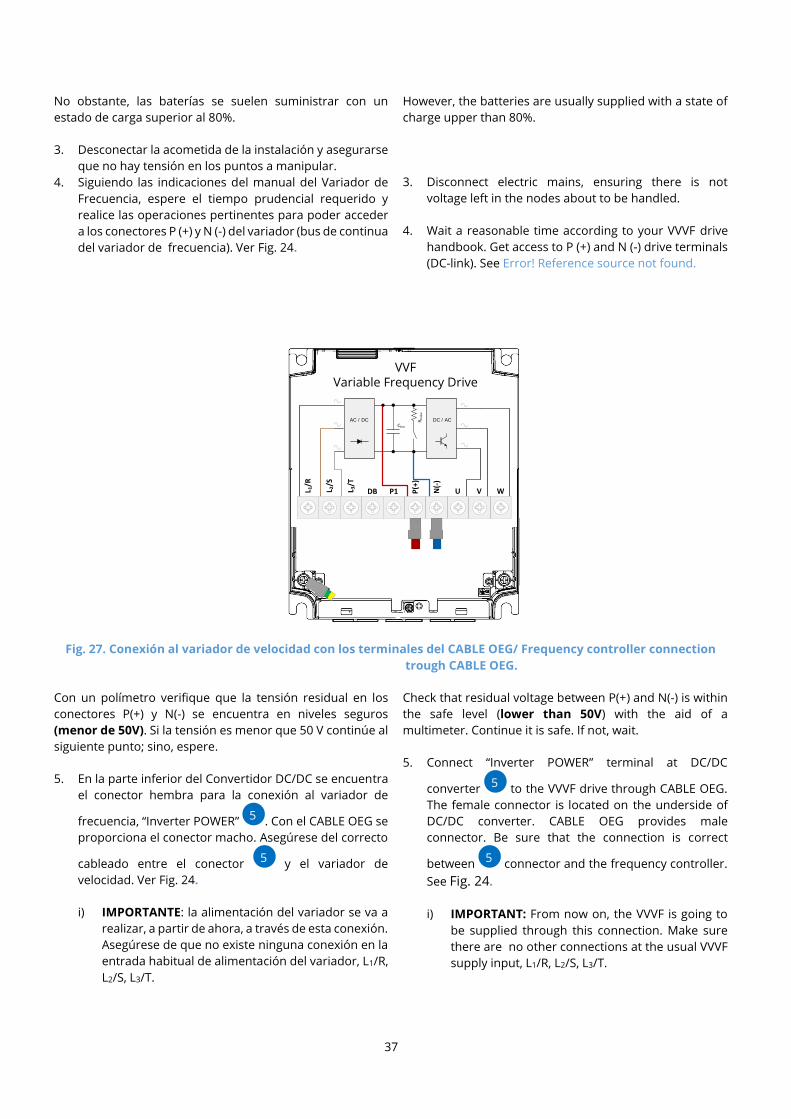
3. Desconectar la acometida de la instalación y asegurarse
que no hay tensión en los puntos a manipular.
4. Siguiendo las indicaciones del manual del Variador de
Frecuencia, espere el tiempo prudencial requerido y
realice las operaciones pertinentes para poder acceder
a los conectores P (+) y N (-) del variador (bus de continua
del variador de frecuencia). Ver Fig. 24.
However, the batteries are usually supplied with a state of
charge upper than 80%.
3. Disconnect electric mains, ensuring there is not
voltage left in the nodes about to be handled.
4. Wait a reasonable time according to your VVVF drive
handbook. Get access to P (+) and N (-) drive terminals
(DC-link). See Error! Reference source not found.
Fig. 27. Conexión al variador de velocidad con los terminales del CABLE OEG/ Frequency controller connection
trough CABLE OEG.
Con un polímetro verifique que la tensión residual en los
conectores P(+) y N(-) se encuentra en niveles seguros
(menor de 50V). Si la tensión es menor que 50 V continúe al
siguiente punto; sino, espere.
5. En la parte inferior del Convertidor DC/DC se encuentra
el conector hembra para la conexión al variador de
frecuencia, “Inverter POWER” . Con el CABLE OEG se
proporciona el conector macho. Asegúrese del correcto
cableado entre el conector y el variador de
velocidad. Ver Fig. 24.
i) IMPORTANTE: la alimentación del variador se va a
realizar, a partir de ahora, a través de esta conexión.
Asegúrese de que no existe ninguna conexión en la
entrada habitual de alimentación del variador, L1/R,
L2/S, L3/T.
Check that residual voltage between P(+) and N(-) is within
the safe level (lower than 50V) with the aid of a
multimeter. Continue it is safe. If not, wait.
5. Connect “Inverter POWER” terminal at DC/DC
converter to the VVVF drive through CABLE OEG.
The female connector is located on the underside of
DC/DC converter. CABLE OEG provides male
connector. Be sure that the connection is correct
between connector and the frequency controller.
See Fig. 24.
i) IMPORTANT: From now on, the VVVF is going to
be supplied through this connection. Make sure
there are no other connections at the usual VVVF
supply input, L1/R, L2/S, L3/T.
DC / ACAC / DC Rb
rake
Cbus
L 1/R
L 2/S
L 3/T
VVFVariable Frequency Drive
DB P1 P(+
)
N(-
)
U V W
5
9
5
9
5
9
5

38
ii) IMPORTANTE: el interruptor “ON OFF” del
Convertidor DC/DC debe estar en la posición OFF y
la habilitación externa deshabilitada (CIRCUITO
ABIERTO entre los terminales “ENABLE INVERTER”
y GND ). Ver Fig. 29 y mantener el fusible
abierto para realizar esta conexión.
iii) IMPORTANTE: La potencia máxima del Convertidor
DC/DC depende del modelo, por lo tanto, el
variador deberá estar configurado de tal manera
que en ningún caso el motor demande más de esta
potencia. Para más información, consulte el punto
3.5 “Ajuste de la potencia máxima consumida por el
motor”.
ii) IMPORTANT: DC/DC converter “ON OFF” switch
must be in “OFF” position, and “ENABLE
INVERTER” must be disabled (not short-circuited
and ). See Fig. 29 and keep the fuse
holder open to make this connection.
iii) IMPORTANT: DC/DC converter maximum
nominal power depends on the model. Therefore,
VVVF Drive must never draw power above this
level. More information in section 3.5 “Ajuste de la
potencia máxima consumida por el motor
Fig. 28 Conexión entre Convertidor DC/DC y variador de velocidad/ DC/DC converter to VVVF Drive connection.
Fig. 29 Terminal de entradas desde la maniobra/ Inputs from the controller terminal.
6. Finalmente, se procederá a la colocación de la chapa
exterior de cierre del bastidor de la manera que se
muestra en las imágenes inferiores.
6. Finally, the external closing sheet will be placed as
shown in the image below.
DC / ACAC / DC Rb
rake
Cbus
L 1/R
L 2/S
L 3/T
VVFVariable Frequency Drive
DB P1 P(+
)
N(-
)
U V W
3A
3
A
3C
3
C
10
8 3A 3C
10
8
• Habilitar inversor: cortocircuitar
terminales 3A-3C.
• Habilitar convertidor DC/DC:
cortocircuitar terminales 3A-3B.
• En caso de apagado, la maniobra
debe abrir el contacto 3A-3B
(debe deshabilitar el equipo).
• Enable inverter: shortcircuit 3A-
3C terminals.
• Enable DC/DC converter:
shortcircuit 3A-3B terminals.
• In case of disconnection, the
controller should open 3A-3B
terminals (It must disable the
DC/DC converter).

39
A la izquierda se puede observar la imagen referente al
bastidor de baterías Small. El proceso de cierre del
bastidor consiste en introducir la chapa en el interior de
la bandeja inferior del bastidor. Posteriormente se debe
introducir la pestaña doblada de la chapa en la pletina
situada debajo del portafusibles para que la chapa no se
mueva. Por último, introducir dos tornillos M4 en los
agujeros mostrados en la imagen.
A la derecha se muestra una imagen similar, referente al
bastidor de baterías Médium. El proceso de cierre del
bastidor es el mismo, pero en este caso hay dos pletinas
situadas en las dos esquinas superiores del bastidor.
Por último, introducir dos tornillos M4 en los agujeros
mostrados en la imagen.
In the left-hand picture you can see the image
regarding the Small battery rack. To close the rack
insert the sheet into the internal bottom tray of the
rack. Next, insert the folding part of the sheet into the
metal plate placed below the fuse holder. As a final
step, put the M4 screws in the holes of the picture
below.
In the right-hand picture there is a similar image,
isntead showing the Medium battery rack. The rack
closing process is the same as in the previous case, but
now, there are two metal plates in the top corners. As
in the previous case, put the M4 screws into the holes
pictured.
Fig. 30. Montaje chapa de cierre bastidor Small/
Assembly of the Small rack closing sheet.
Además, para la disposición del portafusibles, en el caso del
bastidor Small hay que introducirlo en el carril DIN que se
encuentra fijado a la parte superior del bastidor. En cambio,
para el bastidor médium hay que realizar un par de pasos
más.
En primer lugar, atornillar la chapa metálica negra al bastidor
sirviéndose de un tornillo M5. Ésta chapa será el soporte
sobre el que se atornillará el carril DIN mediante dos
tornillos M4. Por último, introducir el portafusibles sobre el
carril DIN en la posición en la que se ve en la imagen.
Fig. 31. Montaje chapa de cierre bastidor Medium/
Assembly of the Medium rack closing sheet.
In addition, to place the fuse holder in the Small battery
rack, insert into the DIN rail that is fixed at the top side of
the rack. To place the fuse holder in the Medium batteries
rack, you must follow two extra steps.
Firstly, the black metal sheet must be screwed to the rack
using a M5 screw. This sheet will support the DIN rail, which
will be screwed using two M4 screws. Secondly, the fuse
holder must be inserted into the DIN rail as shown in the
picture below.
If you need indications to carry out the assembly of the
Large battery rack, contact epic power.

40
Si necesita indicaciones para llevar a cabo el montaje del
bastidor de baterías large, póngase en contacto con epic
power.
Fig. 32. Montaje del portafusibles en el bastidor médium/ Assembly of the fuse-holder in medium rack.
En este punto el P2S ya está instalado y listo para la primera
puesta en marcha.
At this point, P2S system is already installed and ready for
the first start up.
ATENCIÓN
ES FUNDAMENTAL realizar la conexión del
conductor de tierra y el conductor de protección
de ésta (de sección mínima 2.5 mm2).
En caso de pérdida de la conexión a tierra el
equipo seguirá funcionando, pero su
envolvente perderá la equipotencialidad con la
tierra de la instalación. Aparte de proporcionar
un nivel de seguridad superior para el operario,
en caso de no conectarlo, el P2S podría llegar a
dañarse.
WARNING
IT IS ESSENTIAL to earth the conductor
(minimum 2.5 mm2 section).
If the connection stops, the system will keep
on working, but will be isolated from the earth
connection. It may become dangerous for
operators, and the system may be damaged.
ATENCIÓN
ASEGÚRESE DE realizar las conexiones con la
alimentación APAGADA y el variador
DESCONECTADO de la red trifásica de
alimentación. En caso contrario hay peligro de
electrocución del operario y riesgo de generar
daños en el variador y/o P2S (altas corrientes
de conexionado).
WARNING
Supply must be shut down, and VVVF Drive
disconnected from three-phase mains before
making any connections. Risk of electrocution
exists for the operator if not completed. The
drive and the P2S system may also become
damaged.

41
ATENCIÓN
En el proceso de CONEXIÓN del módulo de
baterías conecte en primer lugar el cable positivo
(rojo).
En el proceso de DESCONEXIÓN del módulo de
baterías desconecte en primer lugar el cable
negativo (negro).
ATENCIÓN
Tenga en cuenta que tras una desconexión del
sistema P2S el módulo de baterías permanecerá
cargado. NO CORTOCIRCUITE BAJO NINGÚN
CONCEPTO LOS TERMINALES DEL MÓDULO DE
BATERÍAS.
WARNING
During CONNECTION of the battery array, first,
connect the positive wire (red).
During DISCONNECTION of the battery array,
first, disconnect the negative wire (black).
.
WARNING
Remember: battery array will remain charged
after system disconnection. DO NOT SHORT-
CIRCUIT THE BATTERY ARRAY TERMINALS
UNDER ANY CIRCUMSTANCES.

42
3.4. Puesta en marcha del Sistema P2S
3.4.1. Antes de conectar
Una vez realizado todo el proceso descrito en el punto
3.3 “Instalación”, se detalla el proceso de puesta en
marcha. Si se ha llevado correctamente a cabo el
proceso de instalación descrito deberá encontrarse
todo de la siguiente manera. En caso contrario corríjalo.
Toda la alimentación del ascensor deberá
estar desconectada.
Todos los elementos correctamente
fijados.
Convertidor DC/DC, Cargador de baterías,
Inversor monofásico y Baterías cableadas
entre sí.
Todas las conexiones de tierra (Convertidor
DC/DC, Cargador de Baterías e Inversor)
debidamente cableadas. Se recomienda
comprobarlo con un multímetro. La
tensión de baterías deberá estar por
encima de 50V
Protección de baterías abierta (portusibles
abierto).
Interruptor “ON OFF” ( ) del Convertidor
DC/DC en la posición OFF.
Los terminales “ENABLE INVERTER” y
“GND” del Convertidor DC/DC deben
estar en circuito abierto. Ver Error!
Reference source not found.26.
Interruptor ON/OFF ( ) del inversor
monofásico en la posición OFF.
3.4.2. Proceso de conexión: IMPORTANTE
1) Cablear los terminales , y del Cargador de
baterías a la red monofásica (estando protegido por un
interruptor de corte aguas arriba de la conexión para
asegurar de una conexión segura). Esta será la única
toma de energía del ascensor ya que la única conexión
con la acometida es la del Cargador de baterías.
i) 11- Conexión a tierra – (FG).
ii) 12- Conexión AC (Fase) – (AC/L).
iii) 13- Conexión AC (Neutro) – (AC/N).
2) Cierre el porta-fusible (ver Fig. 14).
3.4. P2S System Start Up
3.4.1. Before connecting
Once “Installation” chapter has been completed; you
can proceed with the start-up steps. If you followed
each one of the installation steps, everything should
be found as follows. In any other case, fix it.
Elevator is disconnected from electric
mains.
Each element is well adjusted to the wall.
DC/DC converter, battery charger, single-
phase inverter and batteries are wired.
Each earth connection (DC/DC converter,
battery charger and single-phase
inverter) is properly wired. We
recommend verifying it with a
multimeter. Battery array voltage should
be more than 50V.
Fuse holder is open.
DC/DC converter “ON OFF” switch ( ) in
OFF position.
DC/DC converter “ENABLE INVERTER”
terminals and “GND” must not
be shorted. See Error! Reference source
not found.26.
Single-phase inverter ON/OFF switch (
) in OFF position.
3.4.2. Connection procedure: IMPORTANT
1) Wire batteries charger terminals , y to
single-phase mains. This will be the only source of
energy consumption, as it is the only electric grid
connection (make sure the supply is shut down before
connecting).
i) 11- Earth connection – (FG)
ii) 12- AC (Phase) connection – (AC/L)
iii) 13- AC (Neutral) connection – (AC/N)
2) Close the fuse holder (see Fig. 14).
3) Turn ON DC/DC converter “ON OFF” switch ( ).
4) Connect the battery charger to the grid.
5) Turn ON single-phase inverter “ON/OFF” switch ( ).
13
1
3
12
1
2
11
1
1
25
2
5
3A
3
A
3C
3
C
10
8
25
10
13 12 11
1
25
3A 3C
10
OBLIGATORIO Variador de velocidad trifásico
380 - 400Vac
COMPULSORY Three-phase frequency controller
380 - 400Vac

43
3) Coloque el interruptor “ON OFF” ( ) del Convertidor
DC/DC en posición “ON”.
4) Conecte la alimentación del cargador.
5) Coloque el Interruptor “ON/OFF” ( ) del Inversor
monofásico en la posición ON.
i) El Inversor no proporcionará 230Vac hasta que los
terminales “ENABLE INVERTER” (siguiente punto)
este cortocircuitados.
IMPORTANTE: El inversor monofásico genera una
tensión aislada, por lo tanto, es necesario referenciar
(conectar) una de las salidas del inversor monofásico a
tierra para que las protecciones diferenciales
colocadas a su salida puedan funcionar
correctamente.
6) Los terminales “ENABLE INVERTER” y “COMUN”
del Convertidor DC/DC (ver Fig. 29) tienen que estar
cortocircuitados de manera externa. Si no lo están,
cortocircuítelos.
7) Los terminales “ENABLE DC/DC” y “COMUN”
del Convertidor DC/DC tienen que estar cortocircuitados
de manera externa. Si no lo están, cortocircuítelos de
manera externa.
i) Como hemos comentado anteriormente esta
conexión es importante que esté controlada por la
maniobra para poder tener el control de la
alimentación de variador de velocidad.
8) El ascensor estará listo para funcionar.
NOTA: La alimentación del variador de velocidad tiene
varios niveles de seguridad. Para alimentar el variador
de velocidad es necesario:
i) El Interruptor “ON OFF” ( ) del Convertidor DC/DC
tiene que estar en posición “ON”
ii) Los terminales “ENABLE INVERTER” y “COMUN”
del mismo (ver Error! Reference source not
found.) tienen que estar cortocircuitados de
manera externa.
iii) Los terminales “ENABLE DC/DC” y “COMUN”
del Convertidor DC/DC tienen que estar
cortocircuitados de manera externa.
i) The inverter will not provide 230V AC until
“ENABLE INVERTER” terminals are short circuited
(next step).
IMPORTANT: Single phase inverter generates an
isolated voltage, therefore it is necessary to connect
one of the inverter outputs to earth in order for the
RCD placed below to work correctly.
6) “ENABLE INVERTER” and “COMMON”
terminals of the DC/DC converter (see Fig. 29) must be
short circuited for its correct functioning. If they are
not short circuited, you must short circuit them.
7) “ENABLE DC/DC” and “COMMON” of the
DC/DC converter must be short circuited for its correct
functioning. If they are not short circuited, you must
short circuit them.
i) As commented previously, the ENABLE must be
connected to the controller to be able supply the
frequency drive.
8) The elevator is ready to operate.
NOTE: The frequency controller supply has some
security layers. To feed the frequency controller it is
necessary for:
i) The DC/DC converter “ON OFF” switch ( ) to be
in “ON” position.
ii) “ENABLE INVERTER” and “COMMON”
terminals of the DC/DC converter (see Error!
Reference source not found.26.) to be short
circuited for the correct functioning of the system.
iii) ENABLE DC/DC” and “COMMON” of the
DC/DC converter to be short circuited for the
correct functioning of the system.
3A
3
A
3B
3
B
3A
3
A
3C
3
C
10
8
3A
3
A
3B
3
B
3A
3
A
3C
3
C
25
2
5
10
8
3A
3
B
3B
3
B
3A
3
A
3C
3
C
10
3A
3
B
3B
3
B
3A
3
A
3C
3
C
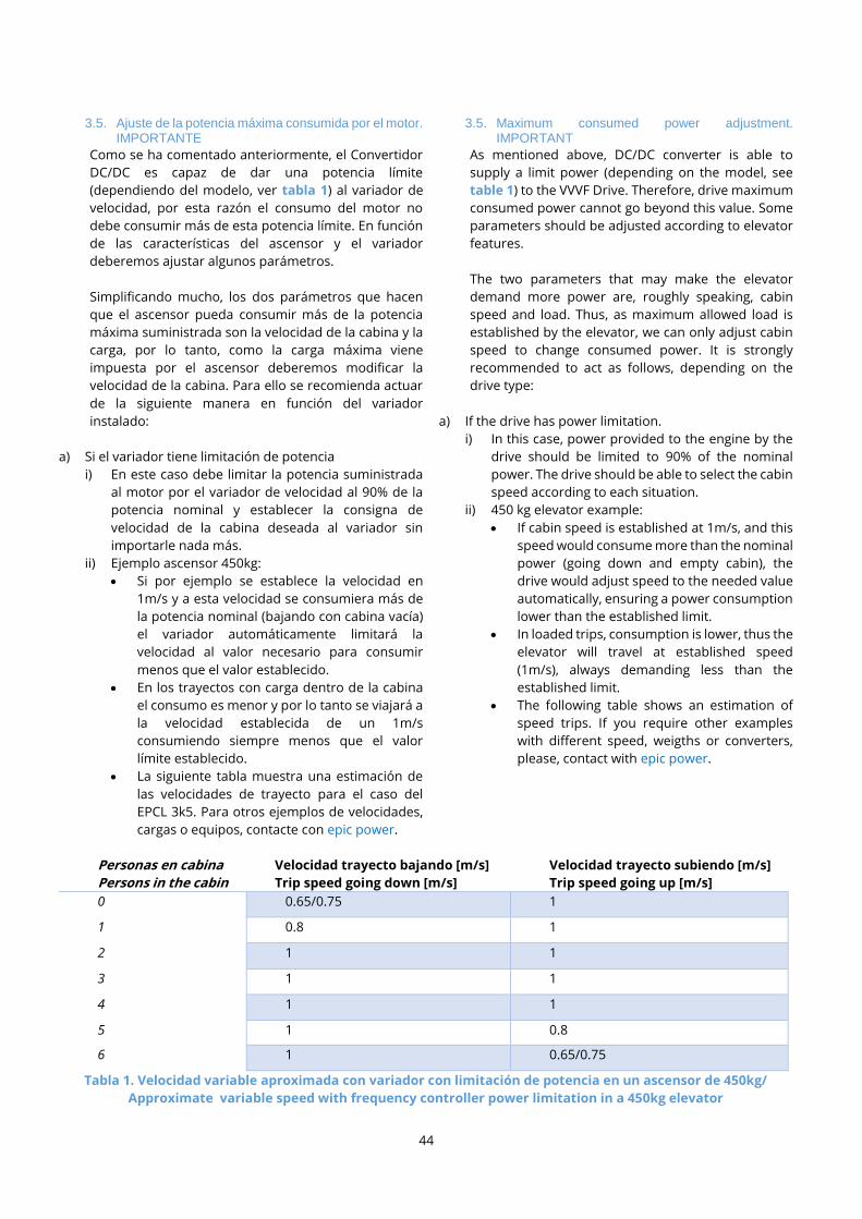
44
3.5. Ajuste de la potencia máxima consumida por el motor. IMPORTANTE
Como se ha comentado anteriormente, el Convertidor
DC/DC es capaz de dar una potencia límite
(dependiendo del modelo, ver tabla 1) al variador de
velocidad, por esta razón el consumo del motor no
debe consumir más de esta potencia límite. En función
de las características del ascensor y el variador
deberemos ajustar algunos parámetros.
Simplificando mucho, los dos parámetros que hacen
que el ascensor pueda consumir más de la potencia
máxima suministrada son la velocidad de la cabina y la
carga, por lo tanto, como la carga máxima viene
impuesta por el ascensor deberemos modificar la
velocidad de la cabina. Para ello se recomienda actuar
de la siguiente manera en función del variador
instalado:
a) Si el variador tiene limitación de potencia
i) En este caso debe limitar la potencia suministrada
al motor por el variador de velocidad al 90% de la
potencia nominal y establecer la consigna de
velocidad de la cabina deseada al variador sin
importarle nada más.
ii) Ejemplo ascensor 450kg:
• Si por ejemplo se establece la velocidad en
1m/s y a esta velocidad se consumiera más de
la potencia nominal (bajando con cabina vacía)
el variador automáticamente limitará la
velocidad al valor necesario para consumir
menos que el valor establecido.
• En los trayectos con carga dentro de la cabina
el consumo es menor y por lo tanto se viajará a
la velocidad establecida de un 1m/s
consumiendo siempre menos que el valor
límite establecido.
• La siguiente tabla muestra una estimación de
las velocidades de trayecto para el caso del
EPCL 3k5. Para otros ejemplos de velocidades,
cargas o equipos, contacte con epic power.
3.5. Maximum consumed power adjustment. IMPORTANT
As mentioned above, DC/DC converter is able to
supply a limit power (depending on the model, see
table 1) to the VVVF Drive. Therefore, drive maximum
consumed power cannot go beyond this value. Some
parameters should be adjusted according to elevator
features.
The two parameters that may make the elevator
demand more power are, roughly speaking, cabin
speed and load. Thus, as maximum allowed load is
established by the elevator, we can only adjust cabin
speed to change consumed power. It is strongly
recommended to act as follows, depending on the
drive type:
a) If the drive has power limitation.
i) In this case, power provided to the engine by the
drive should be limited to 90% of the nominal
power. The drive should be able to select the cabin
speed according to each situation.
ii) 450 kg elevator example:
• If cabin speed is established at 1m/s, and this
speed would consume more than the nominal
power (going down and empty cabin), the
drive would adjust speed to the needed value
automatically, ensuring a power consumption
lower than the established limit.
• In loaded trips, consumption is lower, thus the
elevator will travel at established speed
(1m/s), always demanding less than the
established limit.
• The following table shows an estimation of
speed trips. If you require other examples
with different speed, weigths or converters,
please, contact with epic power.
Personas en cabina
Persons in the cabin
Velocidad trayecto bajando [m/s]
Trip speed going down [m/s]
Velocidad trayecto subiendo [m/s]
Trip speed going up [m/s]
0 0.65/0.75 1
1 0.8 1
2 1 1
3 1 1
4 1 1
5 1 0.8
6 1 0.65/0.75
Tabla 1. Velocidad variable aproximada con variador con limitación de potencia en un ascensor de 450kg/
Approximate variable speed with frequency controller power limitation in a 450kg elevator

45
b) Si el variador no tiene limitación de potencia, pero tiene
posibilidad de monitorizar la potencia consumida en su
pantalla
i) En este caso lo primero que debemos hacer es
configurar el variador para que muestre en su
pantalla la potencia consumida.
ii) Deberemos ajustar los tiempos de aceleración de
cabina a valores que no provoquen consumos
innecesarios que hagan que se requiera más
potencia por parte del motor de la potencia nominal
del convertidor DC/DC (EPCLL)
iii) Según el tipo de ascensor, ver Tabla 2, deberemos
empezar por configurar la velocidad del ascensor
por el menor valor mostrado en la tabla, y ordenar
un viaje de bajada con cabina vacía para comprobar
en la pantalla del variador que la potencia máxima
consumida es menor que la límite.
• Si la potencia consumida es notablemente
menor que el límite podrá subir ligeramente la
velocidad de la cabina y realizar de nuevo el
trayecto de bajada con cabina vacía y
comprobar que se consume de nuevo menos
que la potencia límite. Un buen valor para
ajustar el consumo máximo es un 90% del valor
nominal. De esta manera garantizaremos que,
aunque el motor sufra calentamiento por
tráfico intenso o altas temperaturas, el
consumo nunca será mayor del límite.
• Si la potencia consumida es mayor que la límite,
el variador dejará de funcionar por error de
“undervoltage” (consultar punto 3.5.2) y
deberemos bajar la velocidad más para que el
consumo sea menor del límite.
Si el variador no tiene limitación de potencia ni tiene
posibilidad de monitorizar el consumo en la pantalla
Realizar los pasos indicados en el siguiente diagrama
de flujo, teniendo en cuenta los valores de potencia
nominal mostrados en la tabla 1:
b) If the drive does not have power limitation, but it is
possible to monitor power consumption on the
screen.
i) First of all, we should set the drive to show power
consumption on the screen.
ii) It should be necessary to adjust the acceleration
time parameters (in the VVVF) in order to avoid
unnecessary consumption that make the motor
requires more power than the nominal power of
the DC/DC Converter (EPCLL)
iii) According to elevator type, (see Tabla 2.
Velocidades máximas orientativas) we should
start by setting the lower speed value shown in the
table, and commanding an empty cabin
downward trip. Now we should check on the
screen, that maximum consumed power does not
increase above the limit.
• If consumed power is clearly lower than the
limit, you can slightly increase cabin speed
and repeat the trip, making sure it consumes
less than the limit again. A good value to
establish the limit is a 90% of the nominal
power in such way that guarantees
consumption lower than the nominal power
under any circumstances (high temperatures
or intense traffic).
• If consumed power is higher than the limit,
drive will stop working (“undervoltage error”,
chapter 3.5.2), and we will have to decrease
speed in order to reduce the power below the
limit.
If the drive does not have power limitation and is not
possible to monitor power consumption on the
screen.
Follow the steps as specified in the next figure. The
nominal power values are referred to those in the
table 1:

46
3.5.5. Valores orientativos de velocidad máxima de cabina
A modo orientativo, se presenta la siguiente tabla con
las velocidades a las que normalmente un ascensor se
mueve asumiendo máximo desequilibrio
consumiendo menos de la potencia nominal del
convertidor DC/DC.
3.5.1. Maximum cabin speed guide values
Following table shows maximum speed guide values,
assuming maximum load, so that power consumption
does not exceed the nominal power of the DC/DC
converter.
Carga máxima ascensor
[kg]
Maximum elevator load
[kg]
Tipo de instalación
Installation type
EPCL 3k5
Velocidad máxima [m/s]
Maximum speed [m/s]
EPCL 5k5
Velocidad máxima [m/s]
Maximum speed [m/s]
300 Pórtico/ Hanger 1* 1*
300 Mochila/ Rucksack 1* 1*
450 Pórtico/ Hanger Entre 0.7 y 1** 1*
450 Mochila/ Rucksack Entre 0.5 y 1** 1*
600 Pórtico/ Hanger Entre 0.5 y 0.85** 0.95**
600 Mochila/ Rucksack Entre 0.5 y 0.80** 0.75**
Tabla 2. Velocidades máximas orientativas/ Maximum cabin speed values.
INICIO
Configura el ascensor a la menor velocidad mostrada en la Tabla 1 «Velocidades máximas orientativas» según el tipo de instalación y la
carga máxima.
Realice un trayecto de bajada con la cabina vacía (trayecto de máximo consumo)
¿Se ha realizado el viaje exitosamente (no se ha parado el variador y el consumo es
menor que potencia nominal)?
Realiza diez ciclos de subida y de bajada para comprobar la correcta
instalación.
Reduce la velocidad de cabina 0.1 m/s
¿Ha surgido algún problema en esos
viajes?
Reduce 0.1 m/s la velocidad
SI
SI
NO
NO
Aumente 0.1 m/s la velocidad
Realiza diez ciclos de subida y de bajada para comprobar la correcta
instalación.
¿Ha surgido algún problema en esos
viajes?
FIN
SI
NO
Reduce 0.1 m/s la velocidad
START
Setup the elevator speed with the lowest possible one shown in Table 1 “Orientative maximum speed” depending on the type of
installation and the maximum load
Proceed with a downward trip with no load in the car (maximum conssumption trip)
Repeat 10 cycles of upward and downward trips
Reduce the speed by 0.1 m/s
Has there been a problem?
Reduce 0.1 m/s the speed
YES
YES
NO
NO
Increase the speed by 0.1 m/s
Repeat 10 cycles of upward and downwart trips to veryfy the
correct setup
Has there been a problem?
END
YES
NO
Reduce 0.1 m/s the speed
Is the trip successful? (drive has not stopped and conssumption is
less than the nominal power.

47
* Normalmente estos ascensores pueden moverse
con máximo desequilibrio en cabina consumiendo en
todo caso menos de la potencia nominal definida a
1m/s de velocidad.
** Estas velocidades son orientativas basadas en la
experiencia de diferentes instalaciones.
Previsiblemente la velocidad necesaria para que el
consumo sea menor que la potencia nominal podrá
ser mayor o menor que el rango descrito.
3.5.2. ¿Qué ocurre si no se ajusta correctamente el consumo máximo?
En el caso que el motor demande más potencia de la
marcada como límite en un viaje de bajada con cabina
vacía, el convertidor DC/DC no será capaz de
suministrar esa potencia y por lo tanto la tensión del
bus de continua del variador bajará por debajo del valor
de correcto funcionamiento y el variador se parará por
error de “LOW VOLTAGE”. Ante esta situación, tratar de
ajustar nuevamente la velocidad máxima del ascensor.
* This elevators can usually move at maximum load
and 1m/s, consuming less than the nominal power.
** These values for speed are illustrative, and are
based in experience at different installations.
Needed speed in each case may vary outside
described range.
3.5.2. What if maximum power consumption isn’t well fitted?
In case demanded power is higher than the fixed limit,
DC/DC converter will not be able to provide it. In that
case, drive DC bus voltage will decrease, resulting in
an “under voltage error” and drive will stop working. If
this happen, try to adjust the elevator maximum
speed again.
3.6. Otras conexiones
El convertidor DC/DC cuenta con diferentes conexiones
en su parte superior donde la maniobra o cualquier
otro elemento externo podrá interaccionar o tomar el
control del equipo.
El cableado a la maniobra se encuentra explicado en la
sección 2.1, aunque a continuación se va a dar alguna
indicación importante acerca de las entradas de la
maniobra (3A, 3B y 3C).
3.6. Other connections
P2S converter has different connections on its upper
side, so the elevator controller or any other external
element can take control over it.
All these connectors were already explained in section
2.1. However, it will be given some important
instructions about the inputs of the controller (3A, 3B
y 3C).
NOTA IMPORTANTE SOBRE EL
CONTACTO “ENABLE”: Los contactos de “ENABLE” tienen que ser controlados
externamente. Tanto: “ENABLE DC/DC” y “ENABLE
INVERTER” con “COMUN” tiene dos funciones
importantísimas:
Dejando en circuito abierto el terminal
“ENABLE INVERTER” tanto el DC/DC como el
inversor monofásico dejaran de
proporcionar tensión a su salida.
o Para realizar la deshabilitación completa
del ascensor se deberá abrir el contacto
del terminal “ENABLE INVERTER” y
“GND” .
o Por lo tanto, abrir este contacto asegura
un apagado completo del ascensor
o Para más seguridad, se recomienda abrir
los fusibles de baterías.
o EN UN MODO DE FUNCIONAMIENTO
NORMAL NO SE DEBERÁ ABRIR EL
CONTACTO “ENABLE INVERTER”, SINO
QUE EL APAGADO DE LA MANIOBRA Y/O
NOTE ABOUT “ENABLE”
CONNECTION: The controller should be in charge of enable contacts
“ENABLE DC/DC” and “ENABLE INVERTER”
with “GND” this has two very important
purposes:
In case the elevator is being intentionally
turned off, the contact controlling
“ENABLE INVERTER” should be open, and
thus turn off the drive supply and the
single phase inverter
o In order to make the complete disable of
the lift, “ENABLE INVERTER” and
“GND” should be open.
o Opening these terminals, the shutdown
of the elevator is assured.
o Opening the fuse holders is advisable for
safety.
o DURING NORMAL OPERATION OF THE
ELEVATOR, THE CONTACT “ENABLE
INVERTER” SHOULD NOT BE OPENED.
THE SWITCH OFF OF THE CONTROLLER
3A
3
A
3C
3
C
3A
3
A
3C
3
C
3B
3
B
3A
3
A
3C
3
C
3A
3C 3B
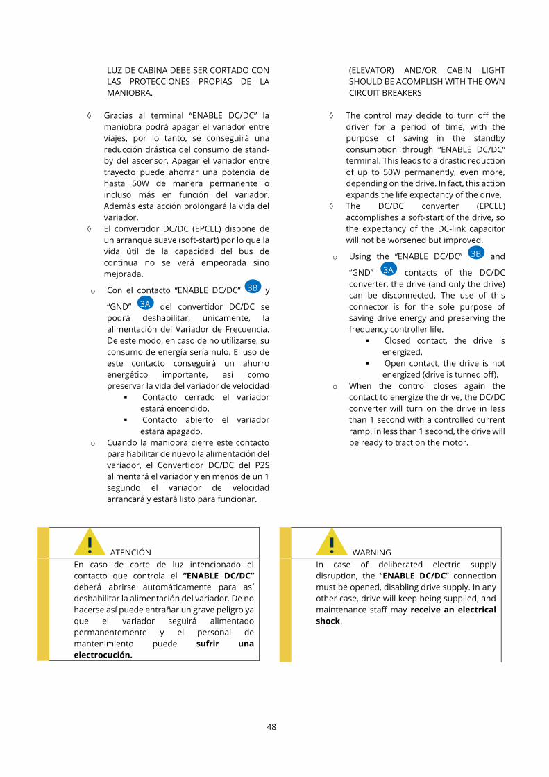
48
LUZ DE CABINA DEBE SER CORTADO CON
LAS PROTECCIONES PROPIAS DE LA
MANIOBRA.
Gracias al terminal “ENABLE DC/DC” la
maniobra podrá apagar el variador entre
viajes, por lo tanto, se conseguirá una
reducción drástica del consumo de stand-
by del ascensor. Apagar el variador entre
trayecto puede ahorrar una potencia de
hasta 50W de manera permanente o
incluso más en función del variador.
Además esta acción prolongará la vida del
variador.
El convertidor DC/DC (EPCLL) dispone de
un arranque suave (soft-start) por lo que la
vida útil de la capacidad del bus de
continua no se verá empeorada sino
mejorada.
o Con el contacto “ENABLE DC/DC” y
“GND” del convertidor DC/DC se
podrá deshabilitar, únicamente, la
alimentación del Variador de Frecuencia.
De este modo, en caso de no utilizarse, su
consumo de energía sería nulo. El uso de
este contacto conseguirá un ahorro
energético importante, así como
preservar la vida del variador de velocidad
▪ Contacto cerrado el variador
estará encendido.
▪ Contacto abierto el variador
estará apagado.
o Cuando la maniobra cierre este contacto
para habilitar de nuevo la alimentación del
variador, el Convertidor DC/DC del P2S
alimentará el variador y en menos de un 1
segundo el variador de velocidad
arrancará y estará listo para funcionar.
ATENCIÓN
En caso de corte de luz intencionado el
contacto que controla el “ENABLE DC/DC”
deberá abrirse automáticamente para así
deshabilitar la alimentación del variador. De no
hacerse así puede entrañar un grave peligro ya
que el variador seguirá alimentado
permanentemente y el personal de
mantenimiento puede sufrir una
electrocución.
(ELEVATOR) AND/OR CABIN LIGHT
SHOULD BE ACOMPLISH WITH THE OWN
CIRCUIT BREAKERS
The control may decide to turn off the
driver for a period of time, with the
purpose of saving in the standby
consumption through “ENABLE DC/DC”
terminal. This leads to a drastic reduction
of up to 50W permanently, even more,
depending on the drive. In fact, this action
expands the life expectancy of the drive.
The DC/DC converter (EPCLL)
accomplishes a soft-start of the drive, so
the expectancy of the DC-link capacitor
will not be worsened but improved.
o Using the “ENABLE DC/DC” and
“GND” contacts of the DC/DC
converter, the drive (and only the drive)
can be disconnected. The use of this
connector is for the sole purpose of
saving drive energy and preserving the
frequency controller life.
▪ Closed contact, the drive is
energized.
▪ Open contact, the drive is not
energized (drive is turned off).
o When the control closes again the
contact to energize the drive, the DC/DC
converter will turn on the drive in less
than 1 second with a controlled current
ramp. In less than 1 second, the drive will
be ready to traction the motor.
WARNING
In case of deliberated electric supply
disruption, the “ENABLE DC/DC” connection
must be opened, disabling drive supply. In any
other case, drive will keep being supplied, and
maintenance staff may receive an electrical
shock.
3A
3
A
3B
3
B
3A
3B

49
4. OPERACIONES DE MANTENIMIENTO
4.1. Mantenimiento del ascensor
Cuando sea necesario APAGAR y MANIPULAR EL
ASCENSOR Y/O EL VARIADOR Y/O EL P2S es necesario
asegurarse de desconectar correctamente el P2S y
asegurarse de que no sigue alimentando el ascensor.
Tenga en cuenta que el sistema P2S está pensado entre
otras cosas para seguir alimentando el ascensor en
caso de corte de luz por lo que deberá operar en
consecuencia.
1) Apague el P2S conmutando a OFF el interruptor del
inversor monofásico ( ) y desconecte el
Convertidor DC/DC, bien con el interruptor o
bien deshabilitando “ENABLE INVERTER”
abriendo el contacto que estará cableado a la
maniobra del ascensor.
i. De esta manera el P2S no estará
alimentando ni la maniobra, ni el variador
de frecuencia.
2) El variador deberá apagarse automáticamente al
haber realizado el paso anterior.
3) Espere el tiempo necesario para que la tensión del
bus de continua baje a valores seguros (indicado en
el manual del variador).
4) Extraiga el conector del convertidor DC/DC.
5) Realice las operaciones requeridas con el variador.
6) Antes de volver a conectar el variador, vuelva a
insertar el conector del P2S.
7) Una vez hayan transcurrido unos 30 segundos,
encienda el P2S conmutando a ON y el interruptor
del inversor monofásico ( ).
8) El ascensor volverá a estar operativo alimentado
desde el sistema P2S.
4. MAINTENANCE
4.1. Elevator maintenance
A correct P2S shutdown, as well as ensuring there is
no supply, is necessary whenever the ELEVATOR
AND/OR THE DRIVE AND/OR THE P2S ARE GOING
TO BE MANIPULATED. Keep in mind that P2S system
is designed, among other things, to keep on supplying
the elevator in case of blackout, so you should act
accordingly.
1) Turn down P2S system by switching OFF single-
phase inverter switch ( ) and disconnect DC/DC
converter with either switch or disabling
“ENABLE INVERTER” by opening the contact,
which will be connected to the controller.
i. This way, P2S system will neither be
supplying the controller nor VVVF drive.
2) Drive should turn down automatically after the
previous step.
3) Wait until DC bus voltage lowers down to safe
level, as long as is necessary (check your drive
handbook).
4) Extract DC/DC converter connector.
5) Perform necessary actions with the drive.
6) Before turning on the drive, connect back P2S
connector .
7) Let 30 seconds elapse, then turn on P2S by
switching on single-phase inverter switch ( ).
8) The elevator will be operational again, supplied
from P2S system.
25
2
5
5
9
5
9
3C
3
C
10
8
25
2
5
25
5
5
3C
10
25

50
4.2. Mantenimiento del P2S
El P2S no requiere de ninguna operación específica de
mantenimiento. Es suficiente con verificar
regularmente el estado de los orificios de ventilación,
comprobando que no estén parcialmente obstruidos.
Si se observa un exceso de polvo en alguna superficie,
retiradla con un trapo seco.
Las baterías necesitarán previsiblemente un reemplazo
periódico. Estas están dimensionadas para tener una
duración aproximada de cuatro años con un uso
estándar.
El proceso de desconexión de baterías debe ser inverso
al de conexión. En caso de necesitar un reemplazo de
baterías siga el siguiente orden.
DESCONEXIÓN DE BATERÍAS:
1) Abra los portafusibles.
2) Desconecte el CABLE OEM del terminal negativo de
la batería 4 ( ).
3) Desconecte el CABLE OEI del terminal positivo de la
batería 1 ( ).
4) Desconecte la batería 2 con la batería 3.
5) Desconecte la batería 3 con la batería 4.
6) Desconecte la batería 1 con la batería 2.
7) Podrá retirar las baterías y reemplazarlas por las
nuevas.
8) Para el proceso de instalación de las baterías siga
el orden indicado en el punto 3.3 “Instalación”.
4.2. P2S maintenance
P2S system does not require specific maintenance
actions. Checking vent holes are not clogged should
be enough.
The only elements that will need periodic
replacement are batteries. They are designed to have
an expected lifetime of four years approximately.
Batteries disconnection process should follow the
reverse order than the connection process. In case
batteries replacement is needed, proceed as follows:
BATTERIES DISCONNECTION:
1) Open the fuse-holders.
2) Disconnect CABLE OEM from battery 4 negative
terminal ( ).
3) Disconnect CABLE OEI from battery 1 positive
terminal ( ).
4) Disconnect battery 2 from battery 3.
5) Disconnect battery 3 from battery 4.
6) Disconnect battery 1 from battery 2.
7) You will be able to pull out old batteries and
replace them by new ones.
8) To install the new batteries, follow chapter 3.3
“Installation” steps.
31
3
1
38
3
8
31
1
38
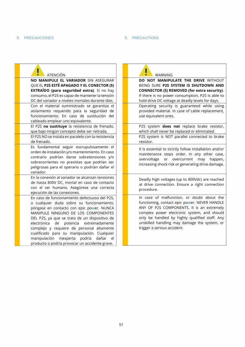
51
5. PRECAUCIONES
ATENCIÓN
NO MANIPULE EL VARIADOR SIN ASEGURAR
QUE EL P2S ESTÉ APAGADO Y EL CONECTOR (5)
EXTRAÍDO (para seguridad extra). Si no hay
consumo, el P2S es capaz de mantener la tensión
DC del variador a niveles mortales durante días.
Con el material suministrado se garantiza el
aislamiento requerido para la seguridad de
funcionamiento. En caso de sustitución del
cableado emplear uno equivalente.
El P2S no sustituye la resistencia de frenado,
que bajo ningún concepto debe ser retirada.
El P2S NO se instala en paralelo con la resistencia
de frenado.
Es fundamental seguir escrupulosamente el
orden de instalación y/o mantenimiento. En caso
contrario podrían darse sobretensiones y/o
sobrecorrientes no previstas que podrían ser
peligrosas para el operario o podrían dañar el
variador.
En la conexión al variador se alcanzan tensiones
de hasta 800V DC, mortal en caso de contacto
con el ser humano. Asegúrese una correcta
ejecución de las conexiones.
En caso de funcionamiento defectuoso del P2S,
o cualquier duda sobre su funcionamiento,
póngase en contacto con epic power. NUNCA
MANIPULE NINGUNO DE LOS COMPONENTES
DEL P2S, ya que se trata de un dispositivo de
electrónica de potencia extremadamente
complejo y requiere de personal altamente
cualificado para su manipulación. Cualquier
manipulación inexperta podría dañar el
producto o podría provocar un accidente grave.
5. PRECAUTIONS
WARNING
DO NOT MANIPULATE THE DRIVE WITHOUT
BEING SURE P2S SYSTEM IS SHUTDOWN AND
CONNECTOR (5) REMOVED (for extra security).
If there is no power consumption, P2S is able to
hold drive DC voltage at deadly levels for days.
Operating security is guaranteed while using
provided material. In case of cable replacement,
use equivalent ones.
P2S system does not replace brake resistor,
which shall never be replaced or eliminated.
P2S system is NOT parallel connected to brake
resistor.
It is essential to strictly follow installation and/or
maintenance steps order. In any other case,
overvoltage or overcurrent may happen,
increasing shock risk or generating drive damage.
Deadly high voltages (up to 800Vdc) are reached
at drive connection. Ensure a right connection
procedure.
In case of malfunction, or doubt about the
functioning, contact epic power. NEVER HANDLE
ANY OF P2S COMPONENTS. It is an extremely
complex power electronic system, and should
only be handled by highly qualified staff. Any
unskilled handling may damage the system, or
trigger a serious accident.

52
6. DATOS TÉCNICOS, DIMENSIONES Y PESOS/ TECHNICAL DATA, DIMENSIONS AND WEIGHTS
6.1. Características técnicas del convertidor DC/DC/ DC/DC converter technical characteristics
Característica/ Feature EPCL 3k5 EPCL 5k5 EPCL 7k EPCL 11k
Rango de tensión de variador operativa
Drive DC operating voltage (Vdc) 500÷800 V 500÷800 V 500÷800 V 500÷800 V
Corriente máxima intercambiada con el
variador de frecuencia
Maximum drive exchanged current
6 A 9.2 A 12 A 18.4 A
Potencia máxima
Maximum power 3,5 kW 5,5 kW 7 kW 11 kW
Rendimiento unidireccional máximo
Maximum unidirectional performance 98 % 98 % 98 % 98 %
Temperatura ambiente almacenamiento
Storage temperature -10÷70 ºC -10÷70 ºC -10÷70 ºC -10÷70 ºC
Peso
Weight 8 kg 11 kg 16 kg 22 kg
Grado de protección IP
IP protection class IP20 IP20 IP20 IP20
Condiciones climáticas
Climatic conditions
Tipo B Tipo B Tipo B Tipo B
Altitud máxima de uso
Maximum use altitude 2000 m 2000 m 2000 m 2000 m
Grado de contaminación
Contamination rank
2 2 2 2
6.2. Características técnicas del cargador de baterías/ Battery charger technical characteristics
Característica/ Feature Valor/ Value
Referencia
Reference HEP-600C-48
Rango de tensión de entrada
Input voltage 90÷305VAC
Rango de tensión de salida
Output voltage 46.1÷60.5V
Corriente máxima de salida
Maximum output current 10.5 A
Potencia máxima
Maximum power 600 W
Temperatura ambiente almacenamiento
Storage temperature -40 ÷85ºC
Peso
Weight 3.9 kg
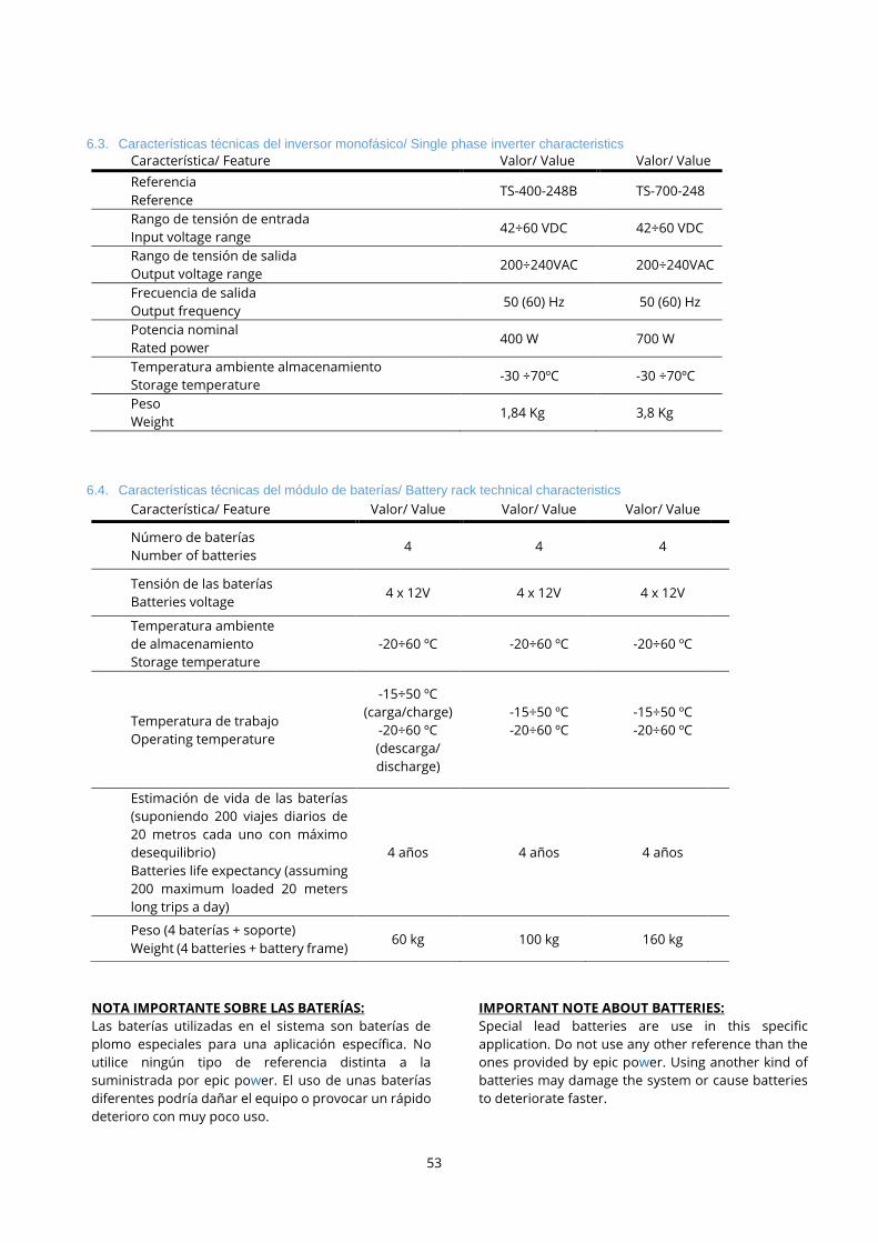
53
6.3. Características técnicas del inversor monofásico/ Single phase inverter characteristics
Característica/ Feature Valor/ Value Valor/ Value
Referencia
Reference TS-400-248B TS-700-248
Rango de tensión de entrada
Input voltage range 42÷60 VDC 42÷60 VDC
Rango de tensión de salida
Output voltage range 200÷240VAC 200÷240VAC
Frecuencia de salida
Output frequency 50 (60) Hz 50 (60) Hz
Potencia nominal
Rated power 400 W 700 W
Temperatura ambiente almacenamiento
Storage temperature -30 ÷70ºC -30 ÷70ºC
Peso
Weight 1,84 Kg 3,8 Kg
6.4. Características técnicas del módulo de baterías/ Battery rack technical characteristics
Característica/ Feature Valor/ Value Valor/ Value Valor/ Value
Número de baterías
Number of batteries 4 4 4
Tensión de las baterías
Batteries voltage 4 x 12V 4 x 12V 4 x 12V
Temperatura ambiente
de almacenamiento
Storage temperature
-20÷60 ºC -20÷60 ºC -20÷60 ºC
Temperatura de trabajo
Operating temperature
-15÷50 ºC
(carga/charge)
-20÷60 ºC
(descarga/
discharge)
-15÷50 ºC
-20÷60 ºC
-15÷50 ºC
-20÷60 ºC
Estimación de vida de las baterías
(suponiendo 200 viajes diarios de
20 metros cada uno con máximo
desequilibrio)
Batteries life expectancy (assuming
200 maximum loaded 20 meters
long trips a day)
4 años 4 años 4 años
Peso (4 baterías + soporte)
Weight (4 batteries + battery frame) 60 kg 100 kg 160 kg
NOTA IMPORTANTE SOBRE LAS BATERÍAS:
Las baterías utilizadas en el sistema son baterías de
plomo especiales para una aplicación específica. No
utilice ningún tipo de referencia distinta a la
suministrada por epic power. El uso de unas baterías
diferentes podría dañar el equipo o provocar un rápido
deterioro con muy poco uso.
IMPORTANT NOTE ABOUT BATTERIES:
Special lead batteries are use in this specific
application. Do not use any other reference than the
ones provided by epic power. Using another kind of
batteries may damage the system or cause batteries
to deteriorate faster.

54
6.5. Dimensiones del Convertidor DC/DC/
Dimensiones EPCL 3k5
6.5. DC/DC converter dimensions
EPCL 3k5 dimensions

55
Dimensiones EPCL 5K5 EPCL 5k5 dimensions

56
6.6. Dimensiones del cargador de baterías 6.6. Battery charger dimensions

57
6.7. Dimensiones del inversor monofásico
6.7. Single-phase inverter dimensions
Inversor TS-400. TS-400 Inverter.

58
Inversor TS-700. TS-700 Inverter.

59
6.8. Dimensiones del Controlador de carga solar
6.8. Solar charge controller dimensions

60
6.9. Dimensiones del módulo de baterías
6.9.5. Bastidor baterías Small 2x2
6.9. Batteries rack dimensions
6.9.1. Small batteries rack 2x2

61
6.9.2. Bastidor baterías Small 4x1 6.9.2. Small batteries rack 4x1

62
6.9.3. Bastidor baterías Medium
6.9.3. Medium batteries rack

63
6.10. Dimensiones del soporte cargador y ondulador
El soporte opcional cargador ondulador tiene unas
dimensiones de 430x380x90mm.
6.10. Holder tray dimensions
The holder tray dimensions are 430x380x90mm.

64
6.11. Dimensiones del armario completo precableado
El armario completo precableado tiene unas
dimensiones de 600x600x205mm.
6.11. Electrical cabinet prewired dimensions
The electrical cabinet prewired dimensions are
600x600x205mm.

65
7. REGLAMENTACIÓN Y NORMATIVA
El P2S ha sido diseñado y fabricado de acuerdo a la
siguiente normativa:
- Reglamento de baja tensión (LVD): Directiva
2006/95/CE del parlamento europeo y del consejo
del 12 de diciembre de 2006 que establece un
Reglamento de Baja Tensión para sistemas
electrónicos.
- UNE-EN 50178:1998
- Reglamento de Compatibilidad
Electromagnética (EMG): Directiva Europea
2004/108/CE que regula la compatibilidad
electromagnética de los equipos y busca garantizar
el funcionamiento del mercado interior exigiendo
que los equipos cumplan un nivel adecuado de
compatibilidad electromagnética.
- UNE-EN 12015:2005
- UNE-EN 12016:2014
7. REGULATIONS
P2S system has been designed and manufactured
according to following regulations:
- Low Voltage Regulations (LVD): 2006/95/CE
Directive from European parliament and the 12
December 2006 council, which establishes low
voltage regulations for electronic systems.
- UNE-EN 50178:1998
- Electromagnetic Compatibility Regulations
(EMG): European directive 2004/108/CE, which
regulates equipment electromagnetic
compatibility and seeks the proper functioning of
internal market, demanding suitable EMC levels.
- UNE-EN 12015:2005
- UNE-EN 12016:2014