Embed Size (px)
Citation preview
2
Table of Contents
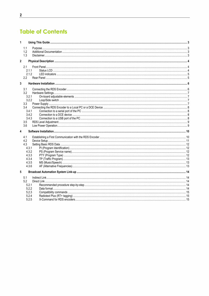
1 Using This Guide ............................................................................................................................................................................................... 3
1.1 Purpose .......................................................................................................................................................................................................... 3 1.2 Additional Documentation .............................................................................................................................................................................. 3 1.3 Disclaimer....................................................................................................................................................................................................... 3
2 Physical Description ......................................................................................................................................................................................... 4
2.1 Front Panel ..................................................................................................................................................................................................... 4 2.1.1 Status LCD ........................................................................................................................................................................................... 4 2.1.2 LED indicators ...................................................................................................................................................................................... 5
2.2 Rear Panel ..................................................................................................................................................................................................... 5
3 Hardware Installation ........................................................................................................................................................................................ 6
3.1 Connecting the RDS Encoder ........................................................................................................................................................................ 6 3.2 Hardware Settings .......................................................................................................................................................................................... 7
3.2.1 On-board adjustable elements ............................................................................................................................................................. 7 3.2.2 Loop/Side switch .................................................................................................................................................................................. 7
3.3 Power Supply ................................................................................................................................................................................................. 7 3.4 Connecting the RDS Encoder to a Local PC or a DCE Device ..................................................................................................................... 8
3.4.1 Connection to a serial port of the PC ................................................................................................................................................... 8 3.4.2 Connection to a DCE device ................................................................................................................................................................ 8 3.4.3 Connection to a USB port of the PC ..................................................................................................................................................... 8
3.5 RDS Level Adjustment ................................................................................................................................................................................... 9 3.6 Low Power Operation ..................................................................................................................................................................................... 9
4 Software Installation ........................................................................................................................................................................................ 10
4.1 Establishing a First Communication with the RDS Encoder ........................................................................................................................ 10 4.2 Device Setup ................................................................................................................................................................................................ 11 4.3 Setting Basic RDS Data ............................................................................................................................................................................... 12
4.3.1 PI (Program Identification) .................................................................................................................................................................. 12 4.3.2 PS (Program Service name) ............................................................................................................................................................... 12 4.3.3 PTY (Program Type) .......................................................................................................................................................................... 12 4.3.4 TP (Traffic Program) ........................................................................................................................................................................... 13 4.3.5 MS (Music/Speech) ............................................................................................................................................................................ 13 4.3.6 AF (Alternative Frequencies) .............................................................................................................................................................. 13
5 Broadcast Automation System Link-up ........................................................................................................................................................ 14
5.1 Indirect Link .................................................................................................................................................................................................. 14 5.2 Direct Link .................................................................................................................................................................................................... 14
5.2.1 Recommended procedure step-by-step ............................................................................................................................................. 14 5.2.2 Data format ......................................................................................................................................................................................... 14 5.2.3 Compatibility commands .................................................................................................................................................................... 15 5.2.4 Radiotext Plus (RT+ tagging) ............................................................................................................................................................. 15 5.2.5 X-Command for RDS encoders .......................................................................................................................................................... 15

3
1 Using This Guide
1.1 Purpose This guide covers P232-based RDS encoders (both module and boxed versions). It provides the information needed to install the equipment and set basic RDS services in order to get your station RDS enabled quickly in a few steps. Please read this entire guide and familiarize yourself with the controls before attempting to use this equipment. Where not otherwise indicated, any information mentioned in relation to the RDS (Radio Data System) applies in full also to the RBDS (Radio Broadcast Data System). If you have any questions or comments regarding this document, please contact us via email. We welcome your feedback.
1.2 Additional Documentation Browse the installation CD or visit the Website for the latest documentation version and the following additional documentation:
P232 RDS Encoder Technical Manual (includes troubleshooting on the last page) (http://pira.cz/rds/p232man.pdf)
Magic RDS Help
Magic RDS Guide – How to... (http://pira.cz/rds/show.asp?art=magic_rds_how_to)
Support section (http://pira.cz/rds/show.asp?art=rds_encoder_support)
X-Command for RDS Encoders (http://pira.cz/rds/xcmd.pdf)
1.3 Disclaimer The equipment has been thoroughly tested and found to be in proper operating condition when shipped. The manufacturer is not liable for any damages, including but not limited to, lost profits, lost savings, or other incidental or consequential damages arising out of the use of this product. No part of this manual may be reproduced or transmitted in any form or by any means, electronic or mechanical, including photocopying, recording or information storage and retrieval systems, for any purpose other than the purchaser's personal use. Information in this document is subject to change without notice. Revision 2017-05-17 Copyright © 1999-2017 PlRA DigitaI s.r.o.
4
2 Physical Description
2.1 Front Panel
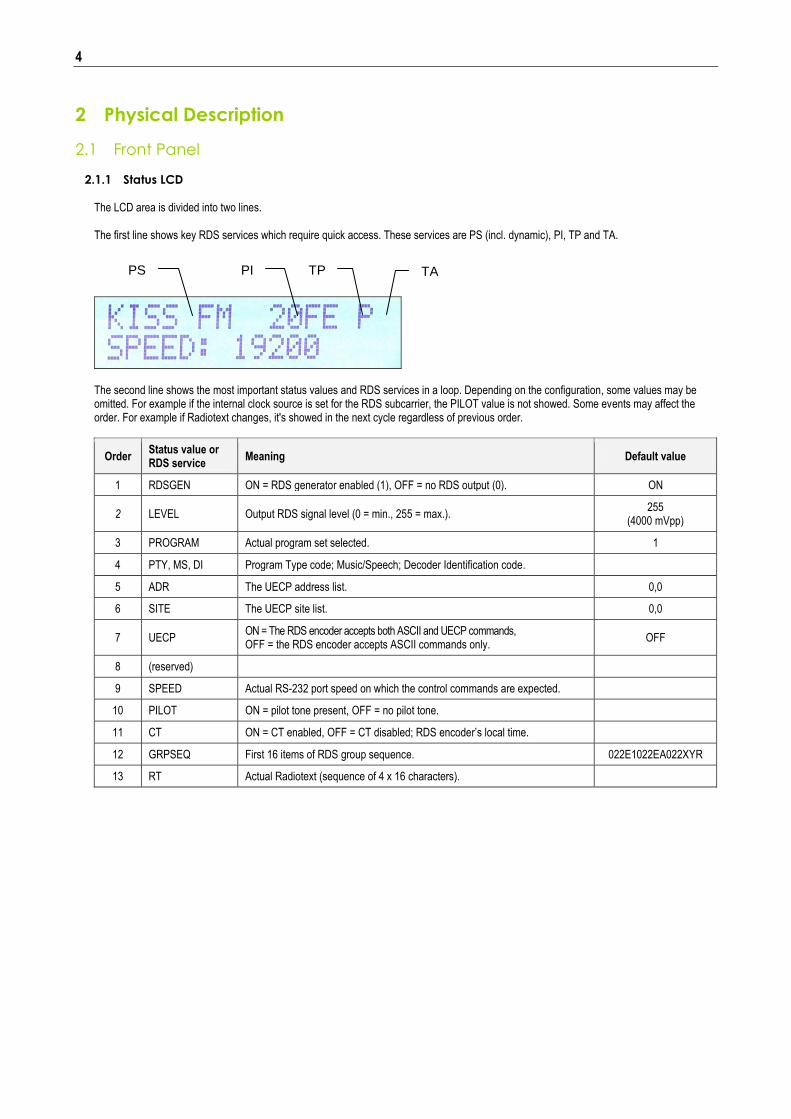
2.1.1 Status LCD
The LCD area is divided into two lines. The first line shows key RDS services which require quick access. These services are PS (incl. dynamic), PI, TP and TA.
The second line shows the most important status values and RDS services in a loop. Depending on the configuration, some values may be omitted. For example if the internal clock source is set for the RDS subcarrier, the PILOT value is not showed. Some events may affect the order. For example if Radiotext changes, it's showed in the next cycle regardless of previous order.
Order Status value or RDS service
Meaning Default value
1 RDSGEN ON = RDS generator enabled (1), OFF = no RDS output (0). ON
2 LEVEL Output RDS signal level (0 = min., 255 = max.). 255
(4000 mVpp)
3 PROGRAM Actual program set selected. 1
4 PTY, MS, DI Program Type code; Music/Speech; Decoder Identification code.
5 ADR The UECP address list. 0,0
6 SITE The UECP site list. 0,0
7 UECP ON = The RDS encoder accepts both ASCII and UECP commands, OFF = the RDS encoder accepts ASCII commands only.
OFF
8 (reserved)
9 SPEED Actual RS-232 port speed on which the control commands are expected.
10 PILOT ON = pilot tone present, OFF = no pilot tone.
11 CT ON = CT enabled, OFF = CT disabled; RDS encoder’s local time.
12 GRPSEQ First 16 items of RDS group sequence. 022E1022EA022XYR
13 RT Actual Radiotext (sequence of 4 x 16 characters).
TP PS PI TA

5
2.1.2 LED indicators
Two LED diodes are used to indicate operating status of the RDS encoder:
Pilot LED Operation LED Status
Start-up on off Initialization
off on Firmware update in progress
Operation
· · · · · Normal operation
- - - - - An error occurred (encoder’s hw failure)
on Receiving data on some port
on External pilot synchronization is active
off Internal clock source is selected
- - - - - Stereo encoder error - pilot tone present but does not meet the specification required. Solution: Switch the RDS encoder to internal clock source.
2.2 Rear Panel
ETH ER N ET R S-232 O U TPU T IN PU T G PIO12V D C
LO O P SID E
Connector or element Description
12V DC Power Supply Power supply connector. See section 3.3 for details.
RS-232 RS-232 standard male type connector. This port is referenced as “Port 1”. For wiring, see the section 3.4. The port is internally optically isolated from the rest of the encoder’s circuitry to prevent ground loops and to keep high ESD immunity and EMC. The encoder operates also with no cable connected.
Output BNC RDS signal output, modulated at 57 kHz subcarrier. If the Loop/Side switch is set to the LOOP position, the Output is a sum of the RDS signal and the signal fed to the Input BNC connector.
Input BNC Optional input for synchronization to the pilot tone or for mixing the RDS signal with existing modulation signal.
Loop/Side switch Allows the input signal to be added to the output signal. See sections 3.1 and 3.2 for details.
GPIO Optional logical inputs for direct control of some RDS services (TA, PROGRAM). See the Technical manual for details. The connector is a standard 6-pin PS/2 type.

6
3 Hardware Installation
3.1 Connecting the RDS Encoder
Basic rules applying for any RDS encoder’s connection: The RDS signal must be fed into modulation input (added to MPX signal if stereo encoder is used). If stereo encoder is used, one of its outputs (MPX or pilot tone) must be fed into the RDS encoder input to meet the synchronization
requirement. Following figures show various situations and corresponding methods of connection. Use shielded cables (e.g. RG58) terminated by BNC male connectors. The cables should be kept short in length. Where necessary, use a BNC ‘T-piece’ for splitting the signal.
Stereo encoder
FM Transm itter
R D S Encoder
M PX inputR D S/SC A /M PX input
Pilot/M PX outputM PX output
Separate stereo encoder - default connection.
Stereo encoder
FM Transm itter
R D S Encoder
M PX input
M PX output
R D S/SC A /M PX input
Stereo encoder with only one MPX output provided.
Stereo encoder
FM Transm itter
R D S Encoder
M PX output
M PX input
R D S/SC A input
FM transmitter with only one MPX input provided.

7
Stereo encoder
FM Transm itter
R D S Encoder
M PX input
M PX output
Both stereo encoder and FM transmitter with only one MPX connector provided - loopthrough mode. Use this mode only if no of the previous connections is possible.
FM Transm itter w ith
integrated stereo encoder
R D S Encoder
Pilot/M PX outputR D S/SC A /M PX input
FM transmitter with integrated stereo encoder. In case of mono transmission (no stereo encoder used) the RDS encoder input may be left unconnected (since there is no need of external synchronization) or it may be used for the audio signal injection in the case that the FM transmitter has only one input connector.
3.2 Hardware Settings
3.2.1 On-board adjustable elements Due to completely DSP-based solution there’s no adjustable element on the board affecting the RDS or MPX signal.
3.2.2 Loop/Side switch Select the LOOP position only if it’s necessary to pass the input signal to the output of the RDS encoder (loopthrough mode). In all other cases the switch must be fixed in the SIDE position! Always make sure that the switch is securely fixed in the position desired and eliminate possibility of unwanted change of its state!
3.3 Power Supply The RDS encoder can be supplied from any power supply, which delivers a stabilized DC 12 V voltage and a current of at least 300 mA. Commonly available switching wall adapters are usually suitable for that purpose. The RDS encoder includes polarity and short-circuit protection. The central conductor of the power supply connector is positive (+). Note: After first power-up, there is no need to configure anything to turn on the RDS subcarrier. The RDS encoder will immediately start to generate the RDS signal with factory default values (PS: * RDS *, PI: FFFF, RDS level: set to maximum 4000 mV p-p).
8
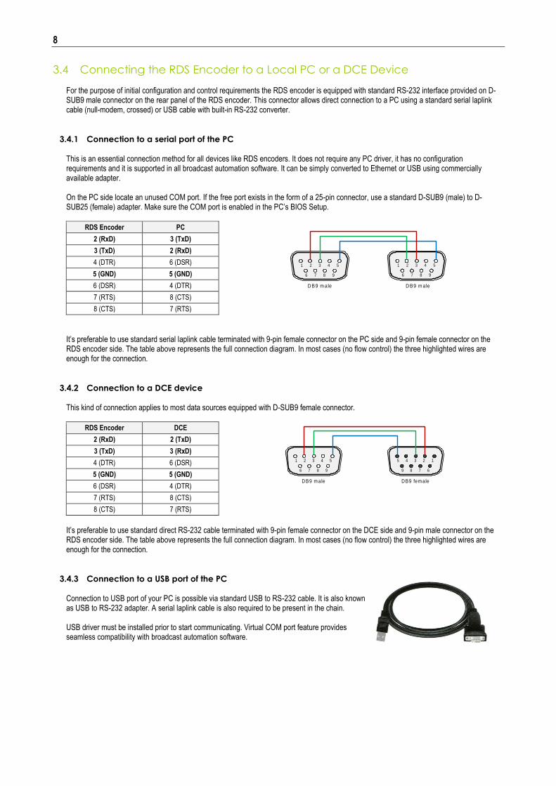
3.4 Connecting the RDS Encoder to a Local PC or a DCE Device For the purpose of initial configuration and control requirements the RDS encoder is equipped with standard RS-232 interface provided on D-SUB9 male connector on the rear panel of the RDS encoder. This connector allows direct connection to a PC using a standard serial laplink cable (null-modem, crossed) or USB cable with built-in RS-232 converter.
3.4.1 Connection to a serial port of the PC This is an essential connection method for all devices like RDS encoders. It does not require any PC driver, it has no configuration requirements and it is supported in all broadcast automation software. It can be simply converted to Ethernet or USB using commercially available adapter. On the PC side locate an unused COM port. If the free port exists in the form of a 25-pin connector, use a standard D-SUB9 (male) to D-SUB25 (female) adapter. Make sure the COM port is enabled in the PC’s BIOS Setup.
RDS Encoder PC
2 (RxD) 3 (TxD)
3 (TxD) 2 (RxD)
4 (DTR) 6 (DSR)
5 (GND) 5 (GND)
6 (DSR) 4 (DTR)
7 (RTS) 8 (CTS)
8 (CTS) 7 (RTS)
It’s preferable to use standard serial laplink cable terminated with 9-pin female connector on the PC side and 9-pin female connector on the RDS encoder side. The table above represents the full connection diagram. In most cases (no flow control) the three highlighted wires are enough for the connection.
3.4.2 Connection to a DCE device This kind of connection applies to most data sources equipped with D-SUB9 female connector.
RDS Encoder DCE
2 (RxD) 2 (TxD)
3 (TxD) 3 (RxD)
4 (DTR) 6 (DSR)
5 (GND) 5 (GND)
6 (DSR) 4 (DTR)
7 (RTS) 8 (CTS)
8 (CTS) 7 (RTS)
It’s preferable to use standard direct RS-232 cable terminated with 9-pin female connector on the DCE side and 9-pin male connector on the RDS encoder side. The table above represents the full connection diagram. In most cases (no flow control) the three highlighted wires are enough for the connection.
3.4.3 Connection to a USB port of the PC Connection to USB port of your PC is possible via standard USB to RS-232 cable. It is also known as USB to RS-232 adapter. A serial laplink cable is also required to be present in the chain. USB driver must be installed prior to start communicating. Virtual COM port feature provides seamless compatibility with broadcast automation software.
1 2 3 4 5
6 7 8 9
D B9 m ale
5 4 3 2 1
9 8 7 6
D B9 fem ale
1 2 3 4 5
6 7 8 9
1 2 3 4 5
6 7 8 9
D B9 m ale D B9 m ale
9
3.5 RDS Level Adjustment Important note: There is no universal setting for the RDS level. Due to different input sensitivity of different FM broadcast equipment it's necessary to check and adjust the RDS level! The correct level should be between 2 and 11 % of the audio multiplex signal, measured by oscilloscope in peak-to-peak values on the modulator input. Recommended value is such that results in 3.4 kHz deviation of the FM carrier. Don’t forget that the maximum total FM carrier deviation with RDS and MPX signal is 75 kHz. It is much easier to use an FM broadcast analyzer for setting the RDS level precisely.
The RDS level can be adjusted after establishing a connection to the encoder, using one of these two methods: In the Windows software Go to Options – Preferences – Control and check the item ‘Enable RDS level control’. Now the control is available on the System sheet in the main window. The software allows adjusting the RDS level in range 0.4 to 100 %. In the P232 RDS encoder, that range is proportional to the output level range of 15.6 to 4000 mV p-p. Confirm the setting by Store button. In terminal, using ASCII command LEVEL=
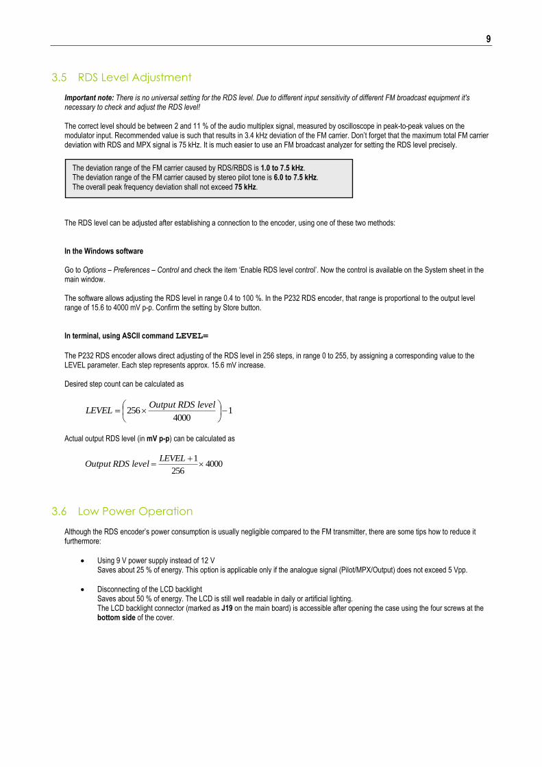
The P232 RDS encoder allows direct adjusting of the RDS level in 256 steps, in range 0 to 255, by assigning a corresponding value to the LEVEL parameter. Each step represents approx. 15.6 mV increase. Desired step count can be calculated as
14000
256
levelRDSOutputLEVEL
Actual output RDS level (in mV p-p) can be calculated as
4000256
1
LEVELlevelRDSOutput
3.6 Low Power Operation Although the RDS encoder’s power consumption is usually negligible compared to the FM transmitter, there are some tips how to reduce it furthermore:
Using 9 V power supply instead of 12 V Saves about 25 % of energy. This option is applicable only if the analogue signal (Pilot/MPX/Output) does not exceed 5 Vpp.
Disconnecting of the LCD backlight Saves about 50 % of energy. The LCD is still well readable in daily or artificial lighting. The LCD backlight connector (marked as J19 on the main board) is accessible after opening the case using the four screws at the bottom side of the cover.
The deviation range of the FM carrier caused by RDS/RBDS is 1.0 to 7.5 kHz. The deviation range of the FM carrier caused by stereo pilot tone is 6.0 to 7.5 kHz.
The overall peak frequency deviation shall not exceed 75 kHz.
10
4 Software Installation
4.1 Establishing a First Communication with the RDS Encoder
The RDS encoder must be configured via local port (port 1) before first use. Please follow these steps:
1. Install the Windows control software called ‘Magic RDS’, run the setup exe file and go through the simple installation wizard.
2. In the case of using USB adapter, install the USB driver now. Pure RS232 connection requires no driver.
3. Make sure the RDS encoder is connected and powered, and all connectors are seated completely.
4. Run the Magic RDS software using Windows Start button.
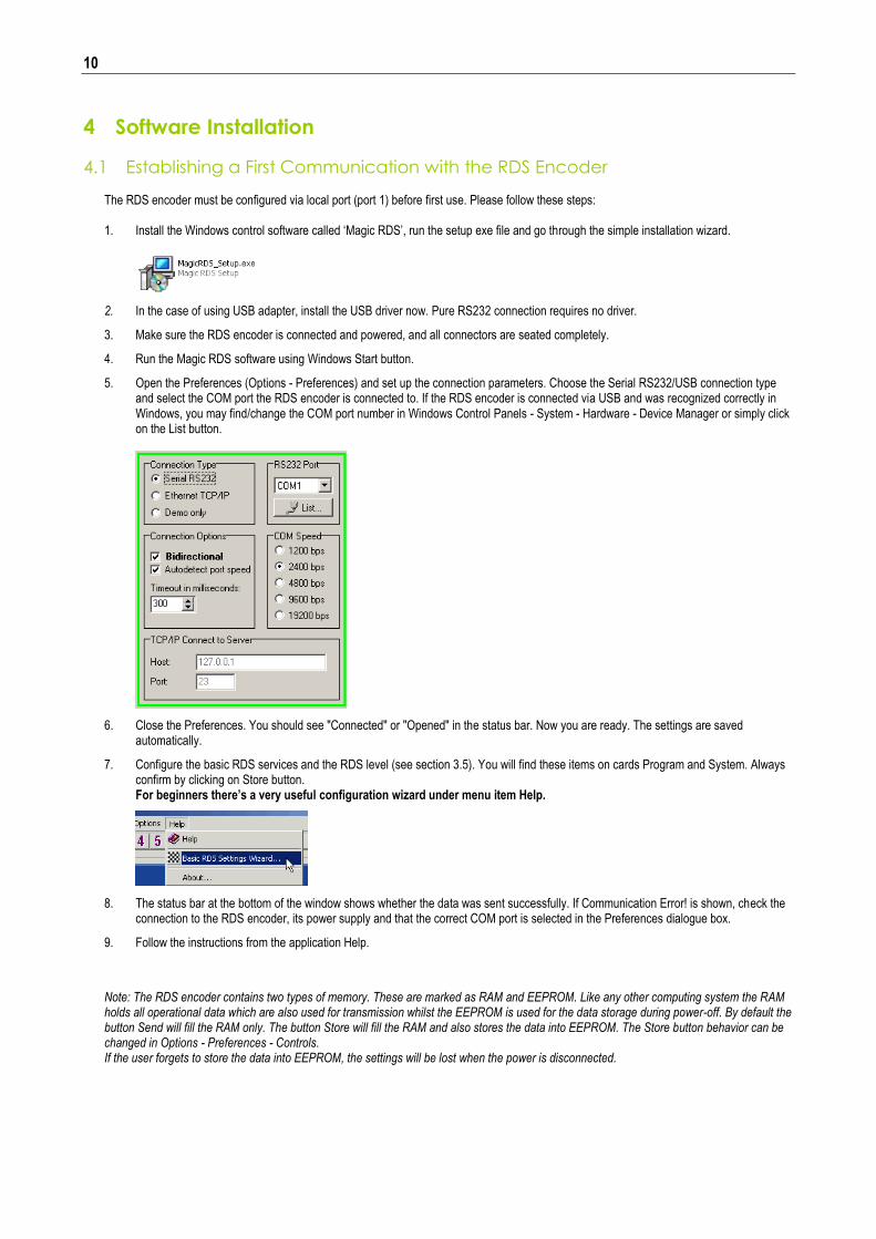
5. Open the Preferences (Options - Preferences) and set up the connection parameters. Choose the Serial RS232/USB connection type and select the COM port the RDS encoder is connected to. If the RDS encoder is connected via USB and was recognized correctly in Windows, you may find/change the COM port number in Windows Control Panels - System - Hardware - Device Manager or simply click on the List button.
6. Close the Preferences. You should see "Connected" or "Opened" in the status bar. Now you are ready. The settings are saved automatically.
7. Configure the basic RDS services and the RDS level (see section 3.5). You will find these items on cards Program and System. Always confirm by clicking on Store button. For beginners there’s a very useful configuration wizard under menu item Help.
8. The status bar at the bottom of the window shows whether the data was sent successfully. If Communication Error! is shown, check the connection to the RDS encoder, its power supply and that the correct COM port is selected in the Preferences dialogue box.
9. Follow the instructions from the application Help.
Note: The RDS encoder contains two types of memory. These are marked as RAM and EEPROM. Like any other computing system the RAM holds all operational data which are also used for transmission whilst the EEPROM is used for the data storage during power-off. By default the button Send will fill the RAM only. The button Store will fill the RAM and also stores the data into EEPROM. The Store button behavior can be changed in Options - Preferences - Controls. If the user forgets to store the data into EEPROM, the settings will be lost when the power is disconnected.
11
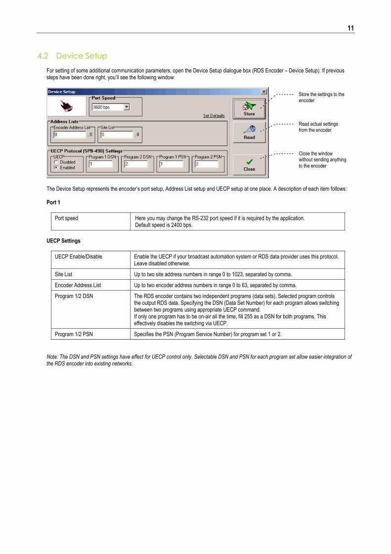
4.2 Device Setup For setting of some additional communication parameters, open the Device Setup dialogue box (RDS Encoder – Device Setup). If previous steps have been done right, you’ll see the following window:
The Device Setup represents the encoder’s port setup, Address List setup and UECP setup at one place. A description of each item follows: Port 1
Port speed Here you may change the RS-232 port speed if it is required by the application. Default speed is 2400 bps.
UECP Settings
UECP Enable/Disable Enable the UECP if your broadcast automation system or RDS data provider uses this protocol. Leave disabled otherwise.
Site List Up to two site address numbers in range 0 to 1023, separated by comma.
Encoder Address List Up to two encoder address numbers in range 0 to 63, separated by comma.
Program 1/2 DSN The RDS encoder contains two independent programs (data sets). Selected program controls the output RDS data. Specifying the DSN (Data Set Number) for each program allows switching between two programs using appropriate UECP command. If only one program has to be on-air all the time, fill 255 as a DSN for both programs. This effectively disables the switching via UECP.
Program 1/2 PSN Specifies the PSN (Program Service Number) for program set 1 or 2.
Note: The DSN and PSN settings have effect for UECP control only. Selectable DSN and PSN for each program set allow easier integration of the RDS encoder into existing networks.
Store the settings to the encoder
Read actual settings from the encoder
Close the window without sending anything
to the encoder
12
4.3 Setting Basic RDS Data Before getting on-air with the RDS signal, you will need to decide on the settings to be used. The following RDS services must be set as the first. Use the Windows control software and its GUI. For more experienced users or those without a Windows PC, any terminal application can be used as well.
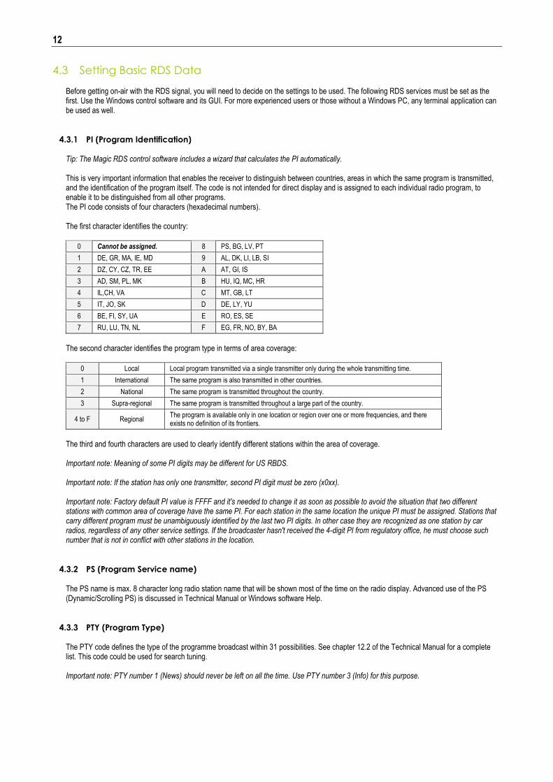
4.3.1 PI (Program Identification) Tip: The Magic RDS control software includes a wizard that calculates the PI automatically. This is very important information that enables the receiver to distinguish between countries, areas in which the same program is transmitted, and the identification of the program itself. The code is not intended for direct display and is assigned to each individual radio program, to enable it to be distinguished from all other programs. The PI code consists of four characters (hexadecimal numbers). The first character identifies the country:
0 Cannot be assigned. 8 PS, BG, LV, PT
1 DE, GR, MA, IE, MD 9 AL, DK, LI, LB, SI
2 DZ, CY, CZ, TR, EE A AT, GI, IS
3 AD, SM, PL, MK B HU, IQ, MC, HR
4 IL,CH, VA C MT, GB, LT
5 IT, JO, SK D DE, LY, YU
6 BE, FI, SY, UA E RO, ES, SE
7 RU, LU, TN, NL F EG, FR, NO, BY, BA
The second character identifies the program type in terms of area coverage:
0 Local Local program transmitted via a single transmitter only during the whole transmitting time.
1 International The same program is also transmitted in other countries.
2 National The same program is transmitted throughout the country.
3 Supra-regional The same program is transmitted throughout a large part of the country.
4 to F Regional The program is available only in one location or region over one or more frequencies, and there exists no definition of its frontiers.
The third and fourth characters are used to clearly identify different stations within the area of coverage. Important note: Meaning of some PI digits may be different for US RBDS. Important note: If the station has only one transmitter, second PI digit must be zero (x0xx). Important note: Factory default PI value is FFFF and it's needed to change it as soon as possible to avoid the situation that two different stations with common area of coverage have the same PI. For each station in the same location the unique PI must be assigned. Stations that carry different program must be unambiguously identified by the last two PI digits. In other case they are recognized as one station by car radios, regardless of any other service settings. If the broadcaster hasn't received the 4-digit PI from regulatory office, he must choose such number that is not in conflict with other stations in the location.
4.3.2 PS (Program Service name) The PS name is max. 8 character long radio station name that will be shown most of the time on the radio display. Advanced use of the PS (Dynamic/Scrolling PS) is discussed in Technical Manual or Windows software Help.
4.3.3 PTY (Program Type) The PTY code defines the type of the programme broadcast within 31 possibilities. See chapter 12.2 of the Technical Manual for a complete list. This code could be used for search tuning. Important note: PTY number 1 (News) should never be left on all the time. Use PTY number 3 (Info) for this purpose.
13
4.3.4 TP (Traffic Program) This is a flag to indicate that the tuned program carries traffic announcements. The TP flag should only be set on programs which dynamically switch on the TA identification during traffic announcements. The flag shall be taken into account during automatic search tuning.
4.3.5 MS (Music/Speech) This is a two-state signal to provide information on whether music or speech is being broadcast. The signal would permit receivers to be equipped with two separate volume controls, one for music and one for speech, so that the listener could adjust the balance between them to suit his individual listening habits.
4.3.6 AF (Alternative Frequencies) The Alternative Frequencies are used to tell receivers what frequencies they can receive the radio station on. This facility is particularly useful in the case of car and portable radios. For this to work, each transmitter must have RDS with the same PI code. Important note: If second PI digit is set to zero (x0xx), this indicates that the station has only one transmitter and the AF list is ignored on most receivers. For further RDS service description visit the Website, section Support.

14
5 Broadcast Automation System Link-up
To send dynamic data via the RDS it's very useful to link the RDS encoder with your broadcast automation system. This usually results in a possibility of sending commercials, actual song information, program announcements and more. Almost any broadcast system can be linked with the P232. The link may be either indirect or direct.
5.1 Indirect Link
Default Windows control software for the P232 RDS encoder is the Magic RDS 3. This application, including documentation and examples of use, can be downloaded from the Website, section Software.
Since probably hundreds of automation systems are used around the world and new versions are released often, information in this document cannot be full-scale. For more information about how to configure the broadcast automation system text output, read its documentation or contact the vendor.
5.2 Direct Link
5.2.1 Recommended procedure step-by-step
1. For the present turn off the RDS encoder support in the broadcast automation system.
2. Connect the RDS encoder and configure all basic parameters like PI, default PS, text setup, enable appropriate text services (usually Radiotext 1). Use the Windows control software or a terminal application. Store all setting into EEPROM. Exit the Windows control software or the terminal.
3. Find out the baudrate (speed) that is used by the broadcast automation system for communicating with the RDS encoder. Configure the connection parameters, using Device setup dialogue box or a terminal.
4. Turn on the RDS encoder support in the broadcast automation system.
Important note: By default only one software application can access one communication port at the same time! For more information about how to control the RDS encoder contact the broadcast automation system vendor.
5.2.2 Data format The P232 RDS encoder supports several formats (protocols) for input data and it’s designed to be compatible with all broadcast automation software which allows direct RDS encoder control. The support includes:
• ASCII commands • UECP protocol (format given by UECP specification) • X-Command (described later in this chapter)
Basic data format for ASCII command is as follows: Prefix (ASCII command): RT1= Terminating character : <CR> (Carriage return). <CR><LF> accepted as well.
15
Example: RT1=Now Playing: Julia Michaels - Issues
See the Technical manual for complete list of all ASCII commands.
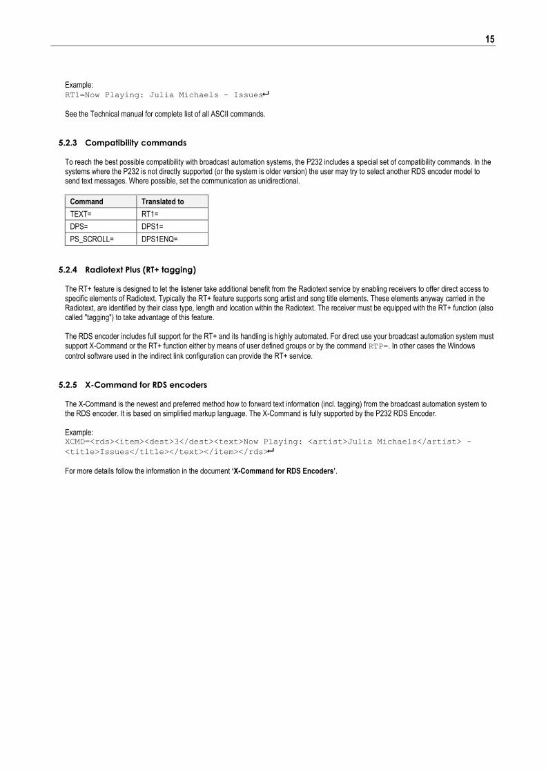
5.2.3 Compatibility commands
To reach the best possible compatibility with broadcast automation systems, the P232 includes a special set of compatibility commands. In the systems where the P232 is not directly supported (or the system is older version) the user may try to select another RDS encoder model to send text messages. Where possible, set the communication as unidirectional.
Command Translated to
TEXT= RT1=
DPS= DPS1=
PS_SCROLL= DPS1ENQ=
5.2.4 Radiotext Plus (RT+ tagging) The RT+ feature is designed to let the listener take additional benefit from the Radiotext service by enabling receivers to offer direct access to specific elements of Radiotext. Typically the RT+ feature supports song artist and song title elements. These elements anyway carried in the Radiotext, are identified by their class type, length and location within the Radiotext. The receiver must be equipped with the RT+ function (also called "tagging") to take advantage of this feature. The RDS encoder includes full support for the RT+ and its handling is highly automated. For direct use your broadcast automation system must support X-Command or the RT+ function either by means of user defined groups or by the command RTP=. In other cases the Windows
control software used in the indirect link configuration can provide the RT+ service.
5.2.5 X-Command for RDS encoders The X-Command is the newest and preferred method how to forward text information (incl. tagging) from the broadcast automation system to the RDS encoder. It is based on simplified markup language. The X-Command is fully supported by the P232 RDS Encoder. Example: XCMD=<rds><item><dest>3</dest><text>Now Playing: <artist>Julia Michaels</artist> -
<title>Issues</title></text></item></rds>
For more details follow the information in the document ‘X-Command for RDS Encoders’.