Embed Size (px)
Citation preview
P15462 – TETHERED WIND ENERGY PLANE
Devin Bunce
Matthew Kennedy
Matthew Maginn
Carl Stahoviak
Matthew Zebert
Agenda• MSD 1
• Project Background• Review of Customer & Engineering Requirements• Proposed System Design
• MSD 2• Manufacturing• Assembly• Pre-Flight Opportunities• Flight Testing• Post-Flight Opportunities• Final System• Accomplishments related to Customer & Engineering Requirements• Risk Review• Lessons Learned• Moving Forward
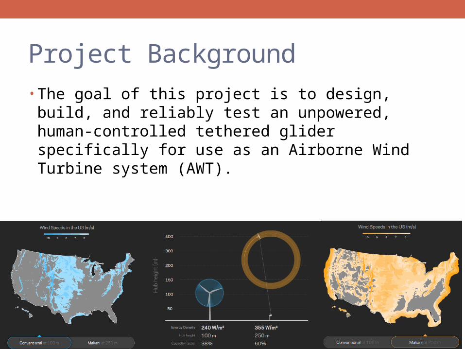
Project Background• The goal of this project is to design, build, and reliably test
an unpowered, human-controlled tethered glider specifically for use as an Airborne Wind Turbine system (AWT).
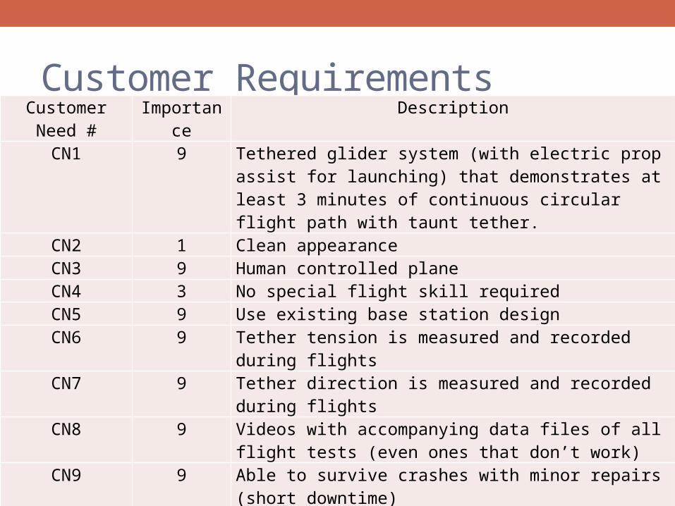
Customer Requirements• Taken from MSD1
Customer Need # Importance Description
CN1 9 Tethered glider system (with electric prop assist for launching) that demonstrates at least 3 minutes of continuous circular flight path with taunt tether.
CN2 1 Clean appearanceCN3 9 Human controlled planeCN4 3 No special flight skill requiredCN5 9 Use existing base station designCN6 9 Tether tension is measured and recorded during flightsCN7 9 Tether direction is measured and recorded during flights
CN8 9 Videos with accompanying data files of all flight tests (even ones that don’t work)
CN9 9 Able to survive crashes with minor repairs (short downtime)
CN10 9 Replaceable PartsCN11 3 Maintenance GuideCN12 9 Design a robust glider which meets the above repair
requirements and can be piloted in the cyclical path.
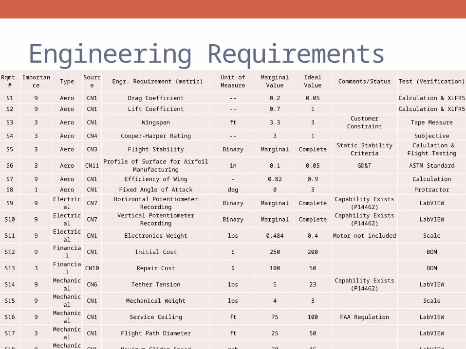
Engineering Requirements• Taken from MSD1
Rqmt. # Importance Type Source Engr. Requirement (metric) Unit of Measure Marginal Value Ideal Value Comments/Status Test (Verification)
S1 9 Aero CN1 Drag Coefficient -- 0.2 0.05 Calculation & XLFR5
S2 9 Aero CN1 Lift Coefficient -- 0.7 1 Calculation & XLFR5
S3 3 Aero CN1 Wingspan ft 3.3 3 Customer Constraint Tape Measure
S4 3 Aero CN4 Cooper-Harper Rating -- 3 1 Subjective
S5 3 Aero CN3 Flight Stability Binary Marginal Complete Static Stability Criteria Calulation & Flight Testing
S6 3 Aero CN11 Profile of Surface for Airfoil Manufacturing in 0.1 0.05 GD&T ASTM Standard
S7 9 Aero CN1 Efficiency of Wing - 0.82 0.9 Calculation
S8 1 Aero CN1 Fixed Angle of Attack deg 0 3 Protractor
S9 9 Electrical CN7 Horizontal Potentiometer Recording Binary Marginal Complete Capability Exists (P14462) LabVIEW
S10 9 Electrical CN7 Vertical Potentiometer Recording Binary Marginal Complete Capability Exists (P14462) LabVIEW
S11 9 Electrical CN1 Electronics Weight lbs 0.484 0.4 Motor not included Scale
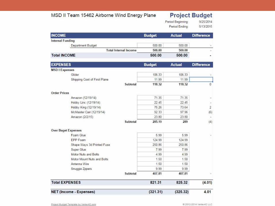
S12 9 Financial CN1 Initial Cost $ 250 200 BOM
S13 3 Financial CN10 Repair Cost $ 100 50 BOM
S14 9 Mechanical CN6 Tether Tension lbs 5 23 Capability Exists (P14462) LabVIEW
S15 9 Mechanical CN1 Mechanical Weight lbs 4 3 Scale
S16 9 Mechanical CN1 Service Ceiling ft 75 100 FAA Regulation LabVIEW
S17 3 Mechanical CN1 Flight Path Diameter ft 25 50 LabVIEW
S18 9 Mechanical CN1 Maximum Glider Speed mph 30 45 LabVIEW
S19 3 Mechanical CN1 Fuselage Cross Sectional Area in2 20 16 Caliper
S20 9 Mechanical CN9 Fuselage Material Tensile Strength psi CF is ideal material MatWeb Lookup
S21 9 Mechanical CN9 Wing Material Tensile Strength psi Foam Mat'l Comparison MatWeb Lookup
S22 3 Time CN9 Repair Downtime hour 24 1 Stopwatch
S23 3 Time CN8 Time Between Flights min 30 5 Stopwatch
S24 3 Time CN4 Training Flight Hours hour 12 1 Training Documetation Stopwatch
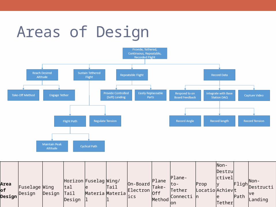
Areas of Design• Design Intent mapped to Physical Parameters• Partially from MSD1
Area of Design
Fuselage Design
Wing Design
Horizontal Tail Design
Fuselage Material
Wing/Tail Material
On-Board Electronics
Plane Take-Off Method
Plane-to-Tether Connection
Prop Location
Non-Destructively Achieve Tether Tension
Flight Path
Non-Destructive Landing
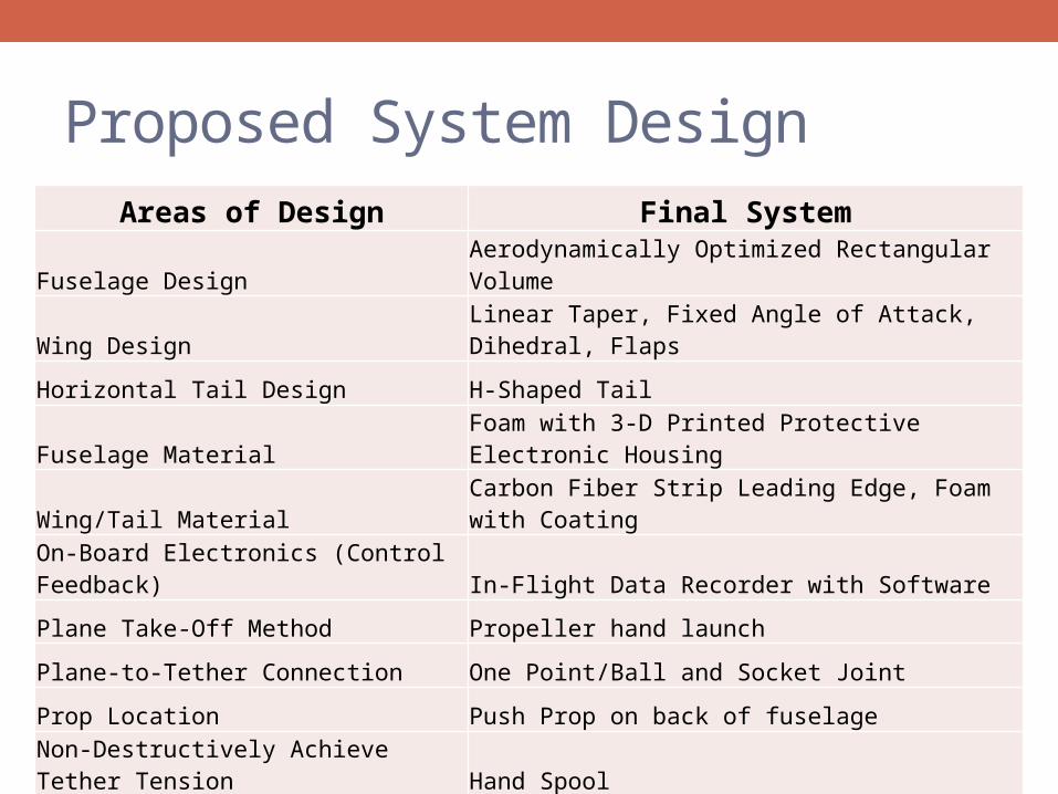
Proposed System Design• Taken from MSD1Areas of Design Final System
Fuselage Design Aerodynamically Optimized Rectangular Volume
Wing Design Linear Taper, Fixed Angle of Attack, Dihedral, Flaps
Horizontal Tail Design H-Shaped Tail
Fuselage Material Foam with 3-D Printed Protective Electronic Housing
Wing/Tail Material Carbon Fiber Strip Leading Edge, Foam with Coating
On-Board Electronics (Control Feedback) In-Flight Data Recorder with Software
Plane Take-Off Method Propeller hand launch
Plane-to-Tether Connection One Point/Ball and Socket Joint
Prop Location Push Prop on back of fuselage
Non-Destructively Achieve Tether Tension Hand Spool
Flight Path Offset Vertical Circle
Non-Destructive Landing Land on Airframe "Smooth"
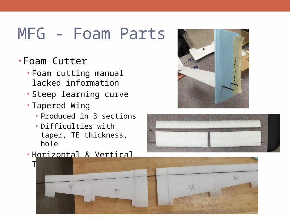
MFG - Foam Parts
• Foam Cutter• Foam cutting manual lacked
information• Steep learning curve• Tapered Wing
• Produced in 3 sections• Difficulties with taper, TE
thickness, hole
• Horizontal & Vertical Tails
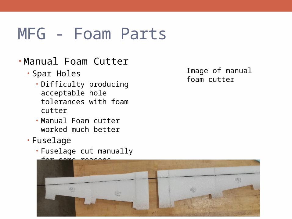
MFG - Foam Parts
• Manual Foam Cutter• Spar Holes
• Difficulty producing acceptable hole tolerances with foam cutter
• Manual Foam cutter worked much better
• Fuselage• Fuselage cut manually for
same reasons
Image of manual foam cutter
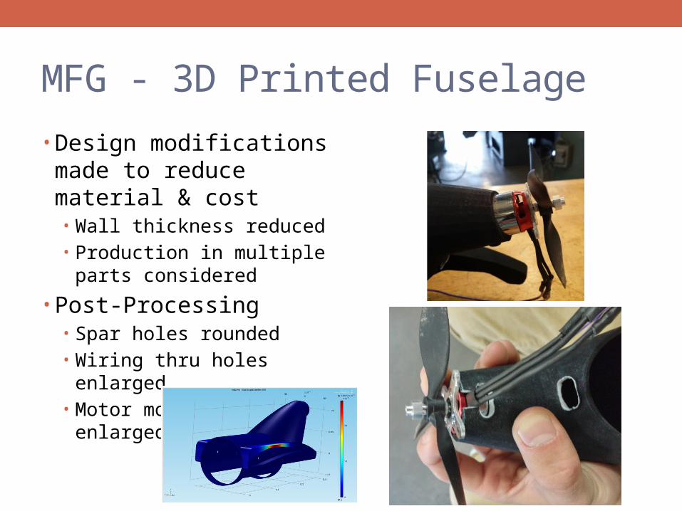
MFG - 3D Printed Fuselage
• Design modifications made to reduce material & cost• Wall thickness reduced• Production in multiple parts
considered
• Post-Processing• Spar holes rounded• Wiring thru holes enlarged• Motor mount hole enlarged
for snug fit
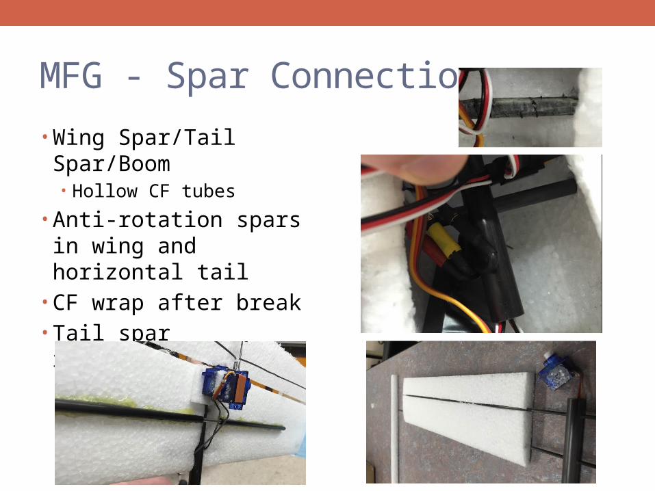
MFG - Spar Connections
• Wing Spar/Tail Spar/Boom• Hollow CF tubes
• Anti-rotation spars in wing and horizontal tail
• CF wrap after break• Tail spar reinforcement
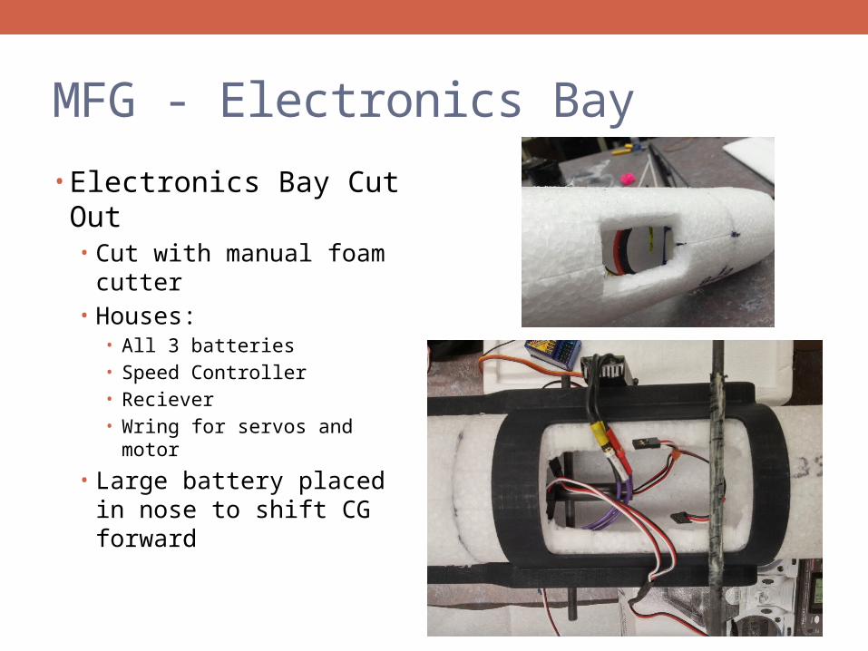
MFG - Electronics Bay
• Electronics Bay Cut Out• Cut with manual foam cutter• Houses:
• All 3 batteries• Speed Controller• Reciever• Wring for servos and motor
• Large battery placed in nose to shift CG forward
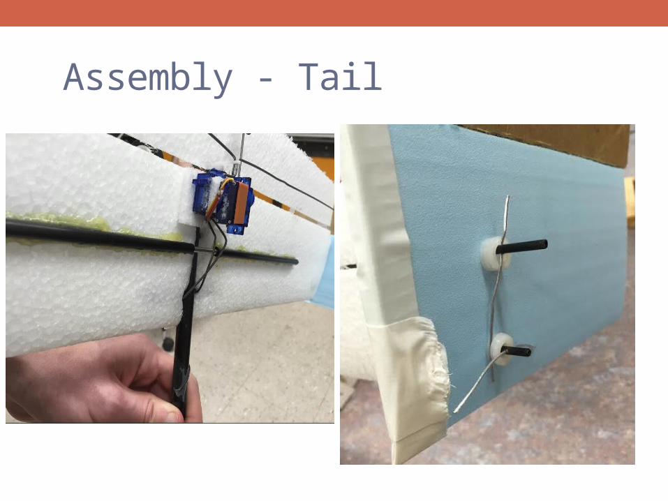
Assembly - Tail
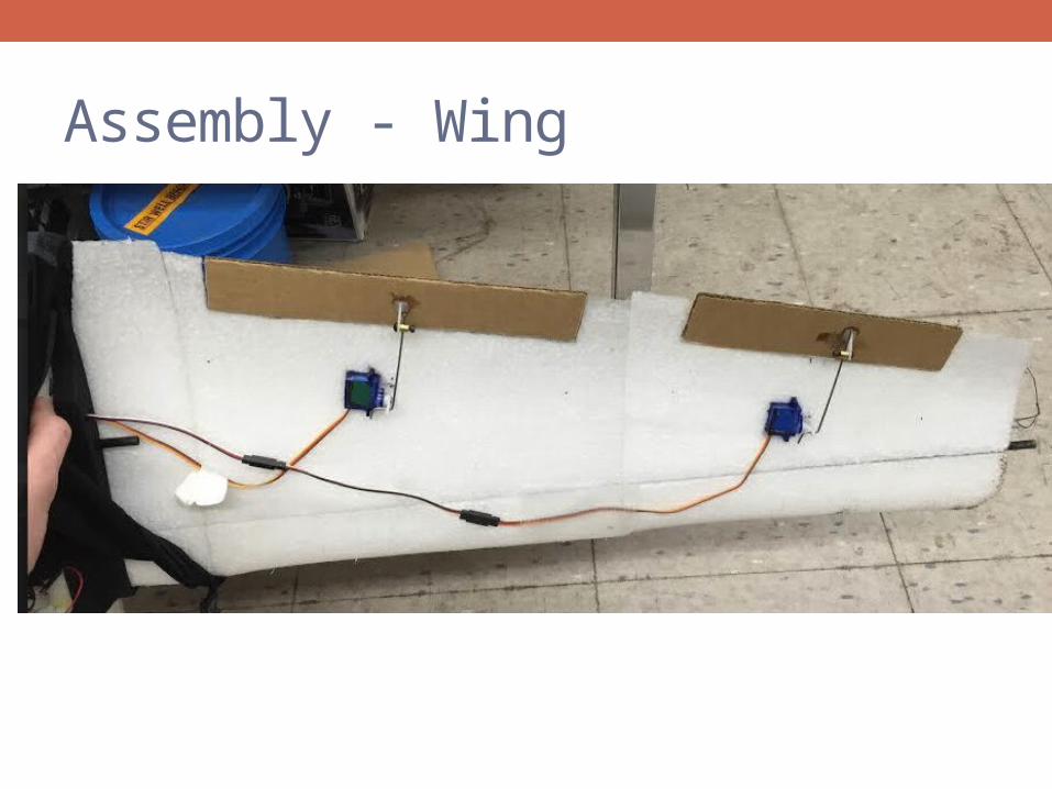
Assembly - Wing
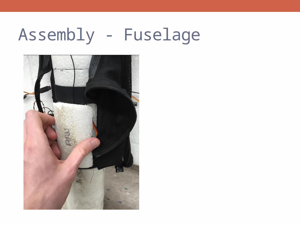
Assembly - Fuselage
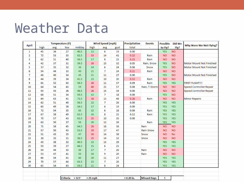
Weather Data
MSD II – Pre-Flight Opportunities• Foam Cutter• Motor Mount/ propeller• Control Surfaces • CG location• Budget Constraints
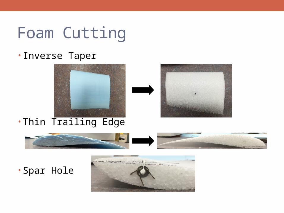
Foam Cutting• Inverse Taper
• Thin Trailing Edge
• Spar Hole
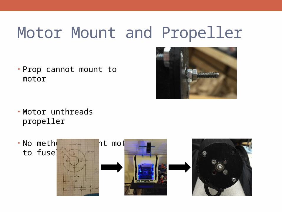
Motor Mount and Propeller
• Prop cannot mount to motor
• Motor unthreads propeller
• No method to mount motor to fuselage
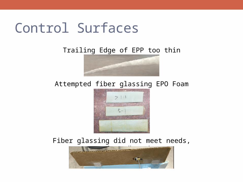
Control Surfaces
Trailing Edge of EPP too thin
Attempted fiber glassing EPO Foam
Fiber glassing did not meet needs, used cardboard
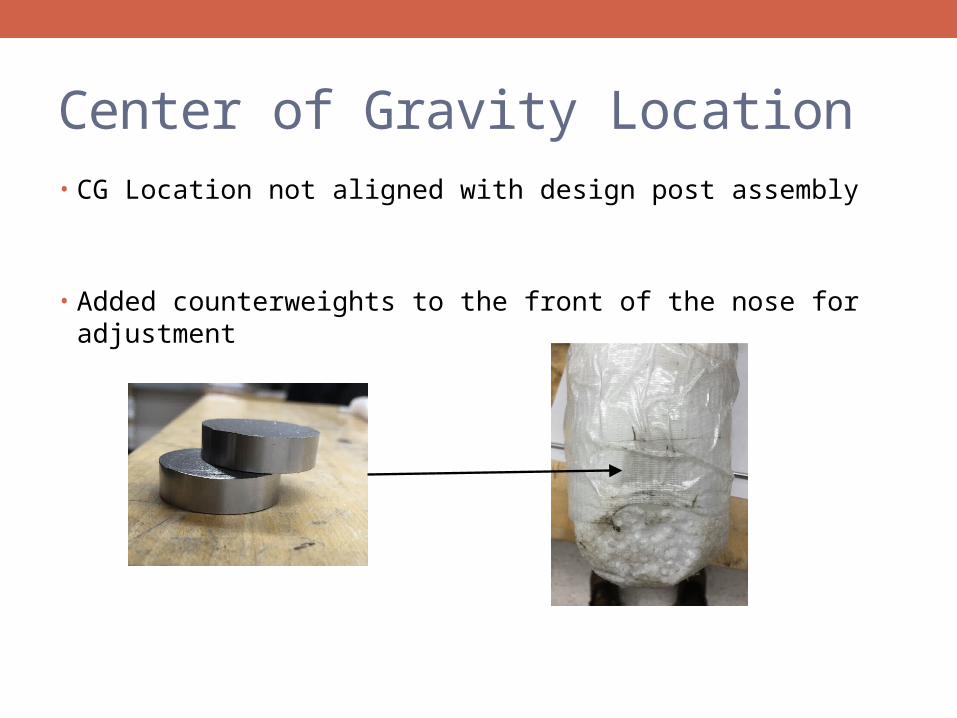
Center of Gravity Location• CG Location not aligned with design post assembly
• Added counterweights to the front of the nose for adjustment
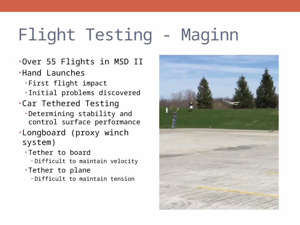
Flight Testing - Maginn
• Over 55 Flights in MSD II• Hand Launches
• First flight impact• Initial problems discovered
• Car Tethered Testing• Determining stability and
control surface performance
• Longboard (proxy winch system)• Tether to board
• Difficult to maintain velocity
• Tether to plane• Difficult to maintain tension
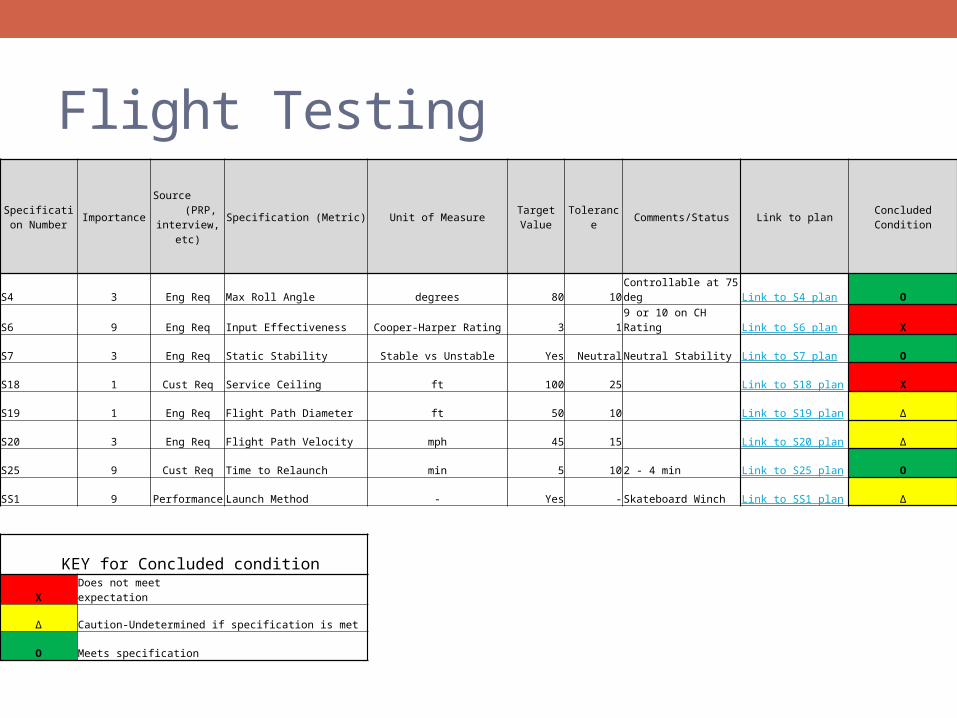
Flight Testing
Specification Number Importance
Source (PRP, interview,
etc)Specification (Metric) Unit of Measure Target Value Tolerance Comments/Status Link to plan Concluded Condition
S4 3 Eng Req Max Roll Angle degrees 80 10 Controllable at 75 deg Link to S4 plan O
S6 9 Eng Req Input Effectiveness Cooper-Harper Rating 3 1 9 or 10 on CH Rating Link to S6 plan X
S7 3 Eng Req Static Stability Stable vs Unstable Yes Neutral Neutral Stability Link to S7 plan O
S18 1 Cust Req Service Ceiling ft 100 25 Link to S18 plan X
S19 1 Eng Req Flight Path Diameter ft 50 10 Link to S19 plan Δ
S20 3 Eng Req Flight Path Velocity mph 45 15 Link to S20 plan Δ
S25 9 Cust Req Time to Relaunch min 5 10 2 - 4 min Link to S25 plan O
SS1 9 Performance Launch Method - Yes - Skateboard Winch Link to SS1 plan Δ
KEY for Concluded condition
X Does not meet expectation
Δ Caution-Undetermined if specification is met
O Meets specification
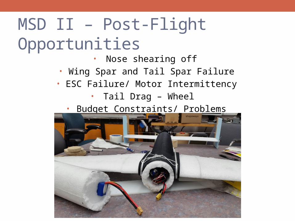
MSD II – Post-Flight Opportunities• Nose shearing off
• Wing Spar and Tail Spar Failure• ESC Failure/ Motor Intermittency
• Tail Drag – Wheel • Budget Constraints/ Problems
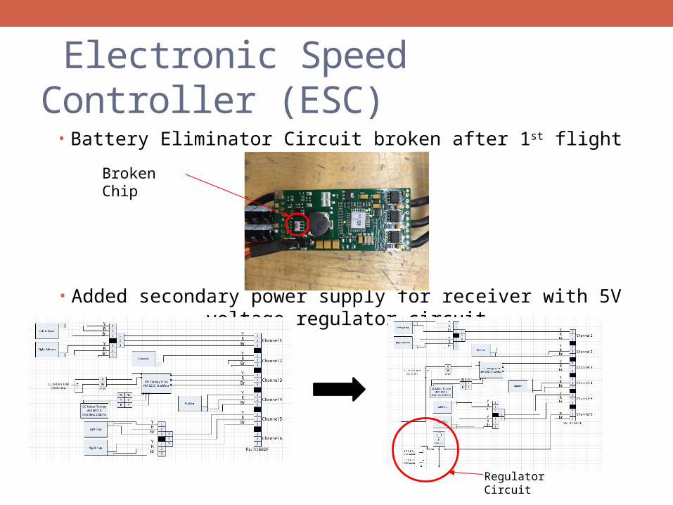
Electronic Speed Controller (ESC)
• Battery Eliminator Circuit broken after 1st flight
• Added secondary power supply for receiver with 5V voltage regulator circuit
Broken Chip
Regulator Circuit
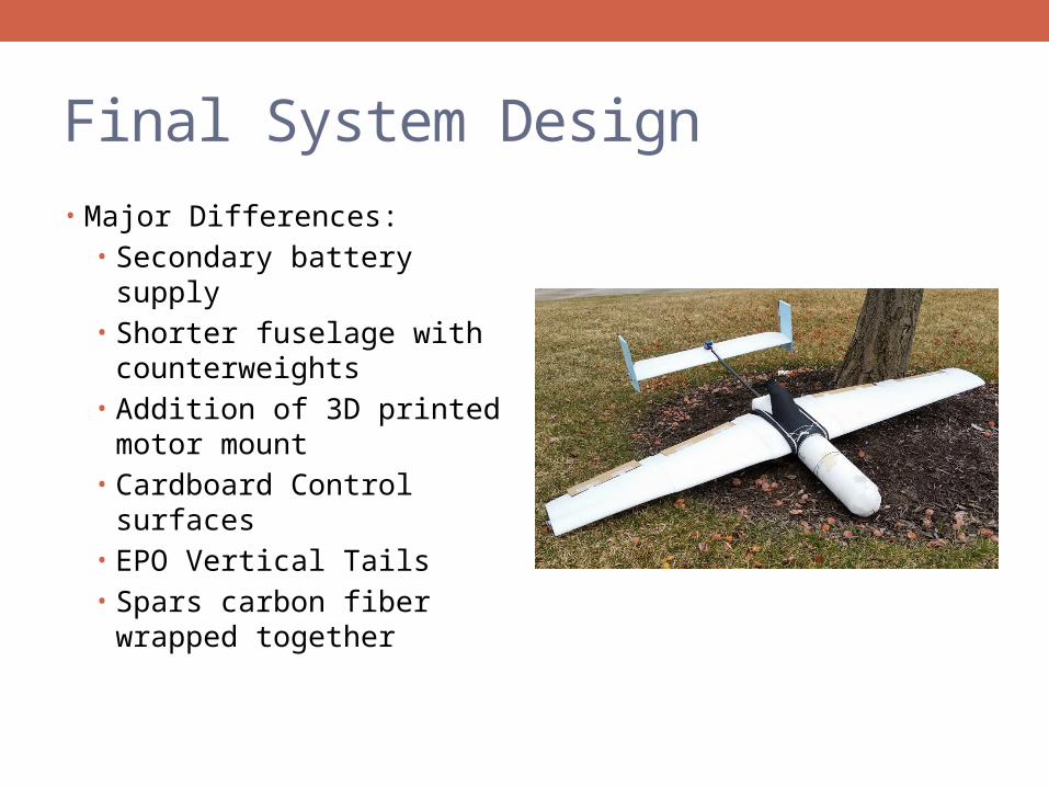
Final System Design
• Major Differences:• Secondary battery supply• Shorter fuselage with
counterweights• Addition of 3D printed motor
mount• Cardboard Control surfaces• EPO Vertical Tails• Spars carbon fiber wrapped
together
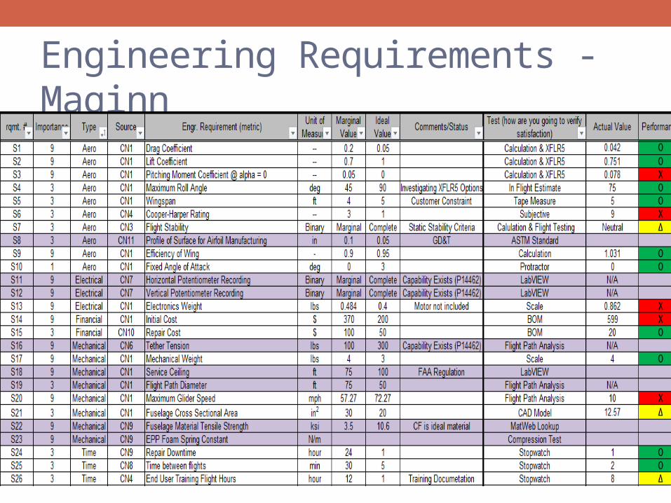
Engineering Requirements - Maginn
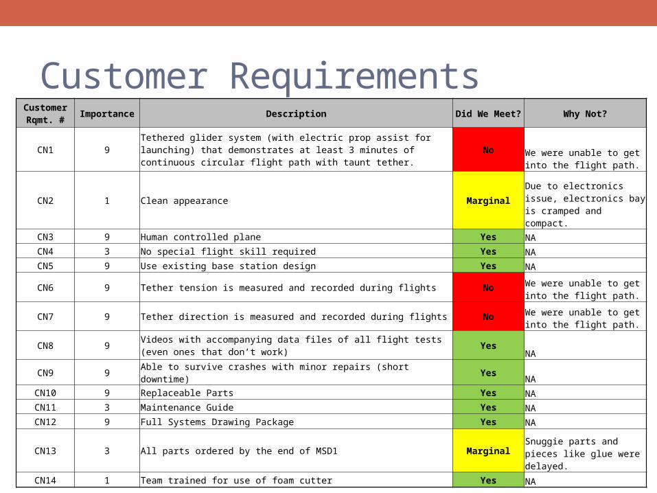
Customer RequirementsCustomer Rqmt. #
Importance Description Did We Meet? Why Not?
CN1 9Tethered glider system (with electric prop assist for launching) that demonstrates at least 3 minutes of continuous circular flight path with taunt tether.
NoWe were unable to get into the flight path.
CN2 1 Clean appearance Marginal Due to electronics issue, electronics bay is cramped and compact.
CN3 9 Human controlled plane Yes NACN4 3 No special flight skill required Yes NACN5 9 Use existing base station design Yes NA
CN6 9 Tether tension is measured and recorded during flights No We were unable to get into the flight path.
CN7 9 Tether direction is measured and recorded during flights No We were unable to get into the flight path.
CN8 9Videos with accompanying data files of all flight tests (even ones that don’t work)
YesNA
CN9 9 Able to survive crashes with minor repairs (short downtime) Yes NACN10 9 Replaceable Parts Yes NACN11 3 Maintenance Guide Yes NACN12 9 Full Systems Drawing Package Yes NA
CN13 3 All parts ordered by the end of MSD1 MarginalSnuggie parts and pieces like glue were delayed.
CN14 1 Team trained for use of foam cutter Yes NA
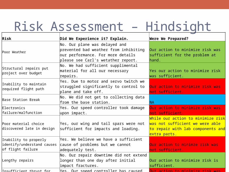
Risk Assessment – Hindsight Risk Did We Experience it? Explain. Were We Prepared?
Poor Weather No. Our plane was delayed and prevented bad weather from inhibiting our performance. For more details please see Carl's wetather report.
Our action to minimize risk was sufficient for the problem at hand.
Structural repairs put project over budget
No. We had sufficient supplimental material for all our necessary repairs. Yes our action to minimize risk was sufficient.
Inability to maintain required flight path Yes. Due to motor and servo twitch we struggled significantly to control to plane and take off. Our action to minimize risk was not sufficient.
Base Station Break No. We did not get to collecting data from the base station. NA
Electronics failure/malfunctionYes. Our speed controller took damage upon impact. Our action to minimize risk was not sufficient.
Poor material choice discovered late in design
Yes, our wing and tail spars were not sufficient for impacts and loading.
While our action to minimize risk was not sufficient we were able to repair with lab components and extra parts.
Inability to properly identify/understand causes of flight failure
Yes. We believe we have a sufficient cause of problems but we cannot adequately test.
Our action to minimze risk was not sufficient.
Lengthy repairs No. Our repair downtime did not extend longer than one day after initial impact fractures. Our action to minimize risk is sufficient.
Insufficient thrust for Take-Off Yes. Our speed controller has caused inconsistency in producing thrust. Our action to minimize risk was not sufficient.
Failure to Land SoftlyYes. Our glider has needed repairs due to hard crashes. Our action to minimize risk was not sufficient.
Wings Dislocate Mid-Flight No. Our wing support was sufficient to prevent dislocation mid flight. Our action to minimize risk was not needed.
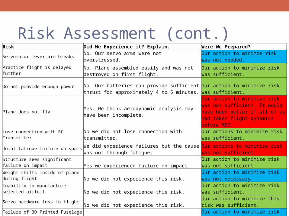
Risk Assessment (cont.)Risk Did We Experience it? Explain. Were We Prepared? Servomotor lever arm breaks No. Our servo arms were not overstressed.
Our action to minimze risk was not needed.
Practice flight is delayed further No. Plane assembled easily and was not destroyed on first flight. Our action to minimize risk was sufficient.
Do not provide enough power No. Our batteries can provide sufficient thrust for approximately 4 to 5 minutes. Our action to minimize risk was sufficient.
Plane does not fly Yes. We think aerodynamic analysis may have been incomplete.
Our action to minimize risk was not sufficient. It would have been better if all of us had taken flight dynamics before MSD.
Lose connection with RC TransmitterNo we did not lose connection with transmitter. Our actions to minimize risk was sufficient.
Joint fatigue failure on spars We did experience failures but the cause was not through fatigue.
Our actions to minimize risk was not sufficient.
Structure sees significant failure on impactYes we experienced failure on impact.
Our action to minimize risk was not sufficient.
Weight shifts inside of plane during flightNo we did not experience this risk.
Our action to minimize risk was not necessary.
Inability to manufacture selected airfoilNo we did not experience this risk. Our action to minimize risk was sufficient.
Servo hardware loss in flightNo we did not experience this risk.
Our action to minimize this risk was sufficient.
Failure of 3D Printed Fuselage Glued Assembly No we did not experience this risk.
Our action to minimize risk was not necessary.
Pilot FatigueNo we did not experience this risk. Our action to minimize risk was sufficient.
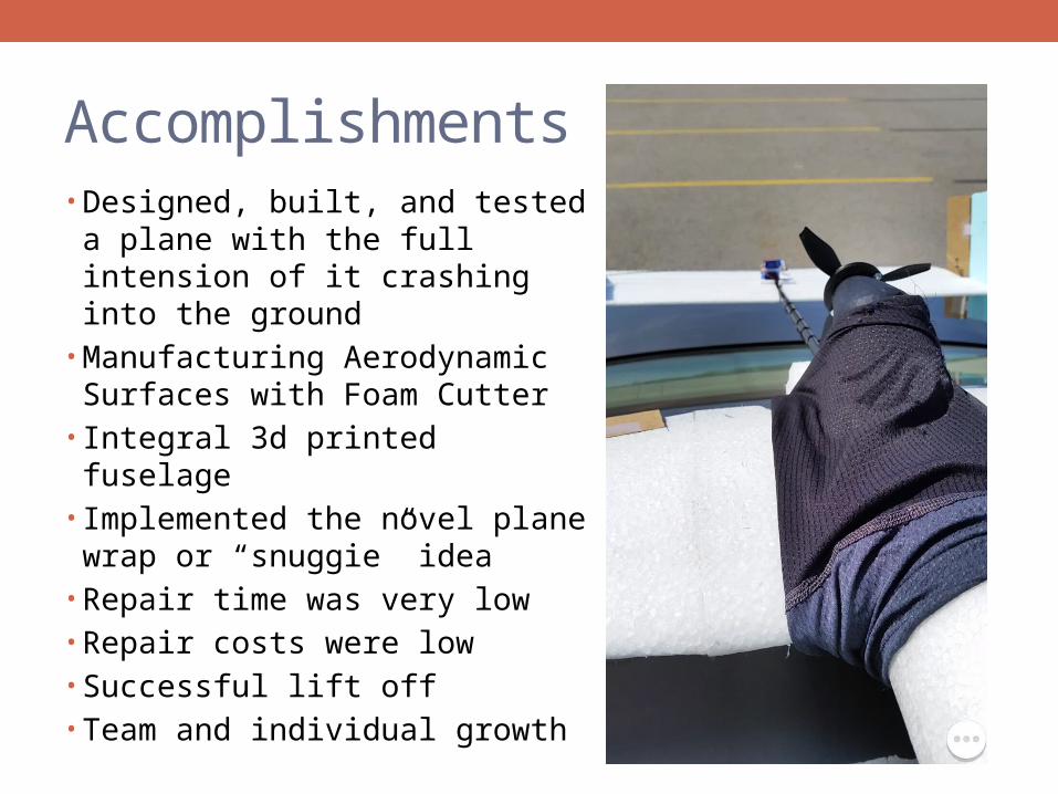
Accomplishments• Designed, built, and tested a
plane with the full intension of it crashing into the ground
• Manufacturing Aerodynamic Surfaces with Foam Cutter
• Integral 3d printed fuselage• Implemented the novel plane
wrap or “snuggie” idea• Repair time was very low• Repair costs were low• Successful lift off• Team and individual growth
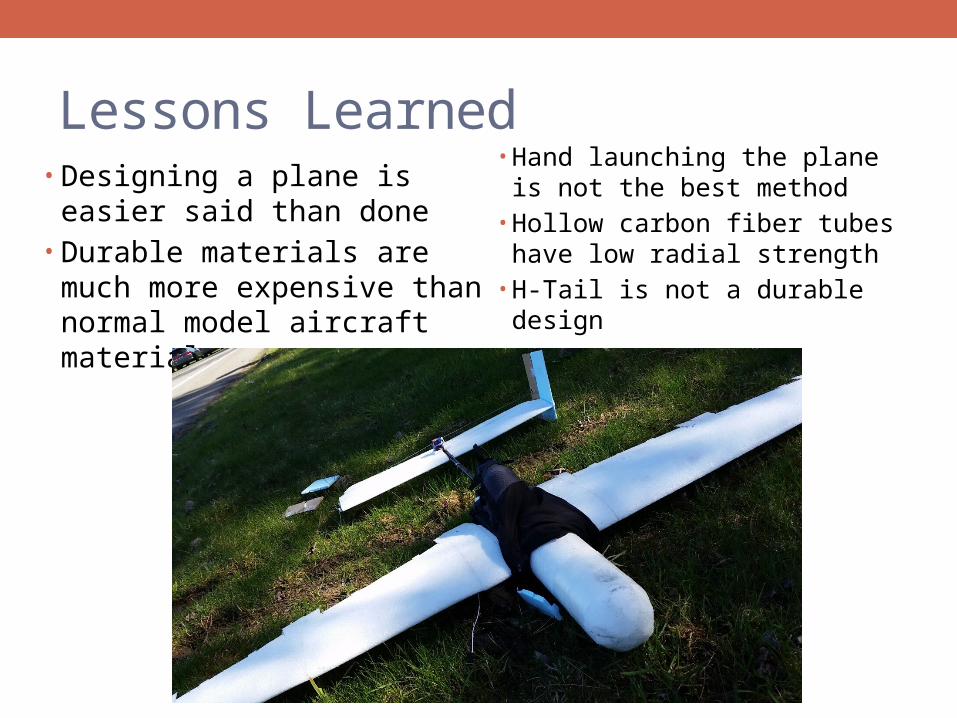
Lessons Learned• Designing a plane is easier said
than done• Durable materials are much
more expensive than normal model aircraft material
• Hand launching the plane is not the best method
• Hollow carbon fiber tubes have low radial strength
• H-Tail is not a durable design
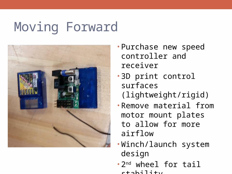
Moving Forward• Purchase new speed
controller and receiver• 3D print control surfaces
(lightweight/rigid)• Remove material from
motor mount plates to allow for more airflow
• Winch/launch system design
• 2nd wheel for tail stability• Snuggie design changes