Embed Size (px)
Citation preview

Augsburg University of Applied Sciences | Faculty of Mechanical and Process Engineering
Brno University of Technology | Faculty of Mechanical Engineering | Institute of Process and Environmental Engineering
Projektování a řízení procesů (KPJ)
Conceptual Design of Distillation, Absorption and Stripping Systems
Prof. Dr.-Ing. Marcus ReppichRoom D5/249 [email protected]
Important notice: These documents are to be used exclusively for study purposes, they are made available to participants of the lecture Conceptual Design of Distillation, Absorption and Stripping Systems (Projektování a řízení procesů, KPJ) at the Institute of Process and Environmental Engineering at the Brno University of Tech-nology only.
Cover image: Copyright by BASF SE
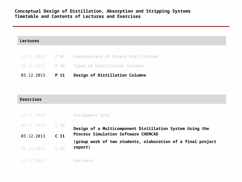
Conceptual Design of Distillation, Absorption and Stripping SystemsTimetable and Contents of Lectures and Exercises
Lectures
19.11.2013 P 09 Fundamentals of Binary Distillation
26.11.2013 P 10 Types of Distillation Columns
03.12.2013 P 11 Design of Distillation Columns
Exercises
19.11.2013 Assignment date
26.11.2013 C 10Design of a Multicomponent Distillation System Using the Process Simulation Software CHEMCAD
(group work of two students, elaboration of a final project report)
03.12.2013 C 11
10.12.2013 C 12
13.12.2013 Due date
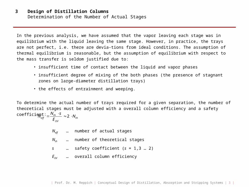
3 Design of Distillation ColumnsDetermination of the Number of Actual Stages
In the previous analysis, we have assumed that the vapor leaving each stage was in equilibrium with the liquid leaving the same stage. However, in practice, the trays are not perfect, i.e. there are devia-tions from ideal conditions. The assumption of thermal equilibrium is reasonable, but the assumption of equilibrium with respect to the mass transfer is seldom justified due to:
• insufficient time of contact between the liquid and vapor phases
• insufficient degree of mixing of the both phases (the presence of stagnant zones on large-diameter distillation trays)
• the effects of entrainment and weeping.
To determine the actual number of trays required for a given separation, the number of theoretical stages must be adjusted with a overall column efficiency and a safety coefficient:
2theff th
OV
N sN N
E
Neff … number of actual stages
Nth … number of theoretical stages
s … safety coefficient (s = 1,3 … 2)
EOV … overall column efficiency
| Prof. Dr. M. Reppich | Conceptual Design of Distillation, Absorption and Stripping Systems | 3 |
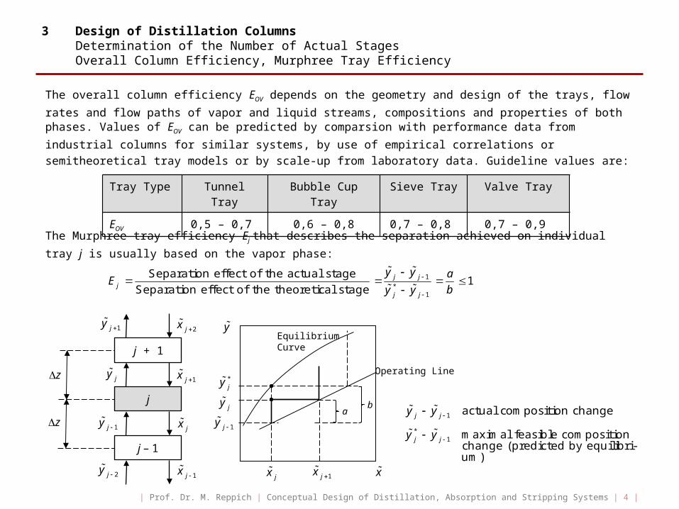
3 Design of Distillation Columns Determination of the Number of Actual Stages Overall Column Efficiency, Murphree Tray Efficiency
The overall column efficiency EOV depends on the geometry and design of the trays, flow rates and flow paths of vapor and liquid streams, compositions and properties of both phases. Values of EOV can be
predicted by comparsion with performance data from industrial columns for similar systems, by use of empirical correlations or semitheoretical tray models or by scale-up from laboratory data. Guideline values are:
The Murphree tray efficiency Ej that describes the separation achieved on individual tray j is usually
based on the vapor phase:
1*
1
Separation effect of the actual stage1
Separation effect of the theoretical stagej j
jj j
y y aE
by y
Tray Type Tunnel Tray Bubble Cup Tray Sieve Tray Valve Tray
EOV 0,5 – 0,7 0,6 – 0,8 0,7 – 0,8 0,7 – 0,9
j + 1
j
j – 1
z
z
jy
1jy
1jy
2jy
1jx
2jx
jx
1jx
y
x
Equilibrium Curve
jy
*jy
1jy
jx 1jx
Operating Line
ab
1 actual composition changej jy y
*1 maximal feasible composition
change (predicted by equilibri-um)
j jy y
| Prof. Dr. M. Reppich | Conceptual Design of Distillation, Absorption and Stripping Systems | 4 |
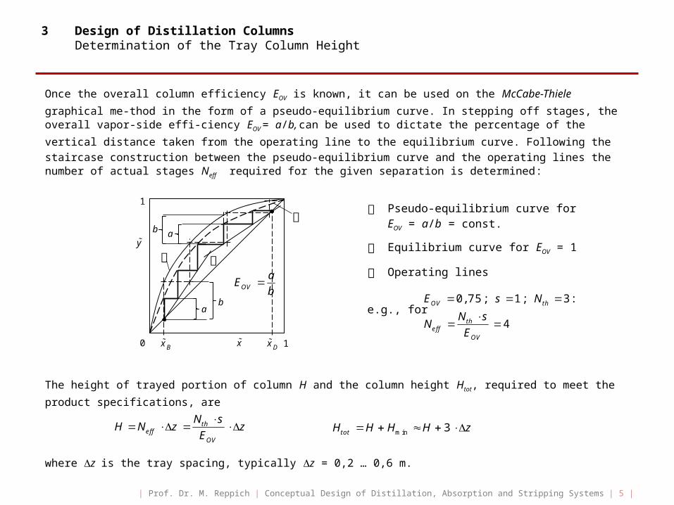
3 Design of Distillation Columns Determination of the Tray Column Height
Once the overall column efficiency EOV is known, it can be used on the McCabe-Thiele graphical me-
thod in the form of a pseudo-equilibrium curve. In stepping off stages, the overall vapor-side effi-ciency EOV = a/b, can be used to dictate the percentage of the vertical distance taken from the operating line
to the equilibrium curve. Following the staircase construction between the pseudo-equilibrium curve and the operating lines the number of actual stages Neff required for the given separation is
determined:
The height of trayed portion of column H and the column height Htot, required to meet the product
specifications, are
where z is the tray spacing, typically z = 0,2 … 0,6 m.
0,75; 1; 3:
4
OV th
theff
OV
E s N
N sN
E
Pseudo-equilibrium curve forEOV = a/b = const.
Equilibrium curve for EOV = 1
Operating lines
e.g., for
theff
OV
N sH N z z
E
min 3totH H H H z
OV
aE
b
y
x0 1
1
Bx Dx
ab
ab
| Prof. Dr. M. Reppich | Conceptual Design of Distillation, Absorption and Stripping Systems | 5 |
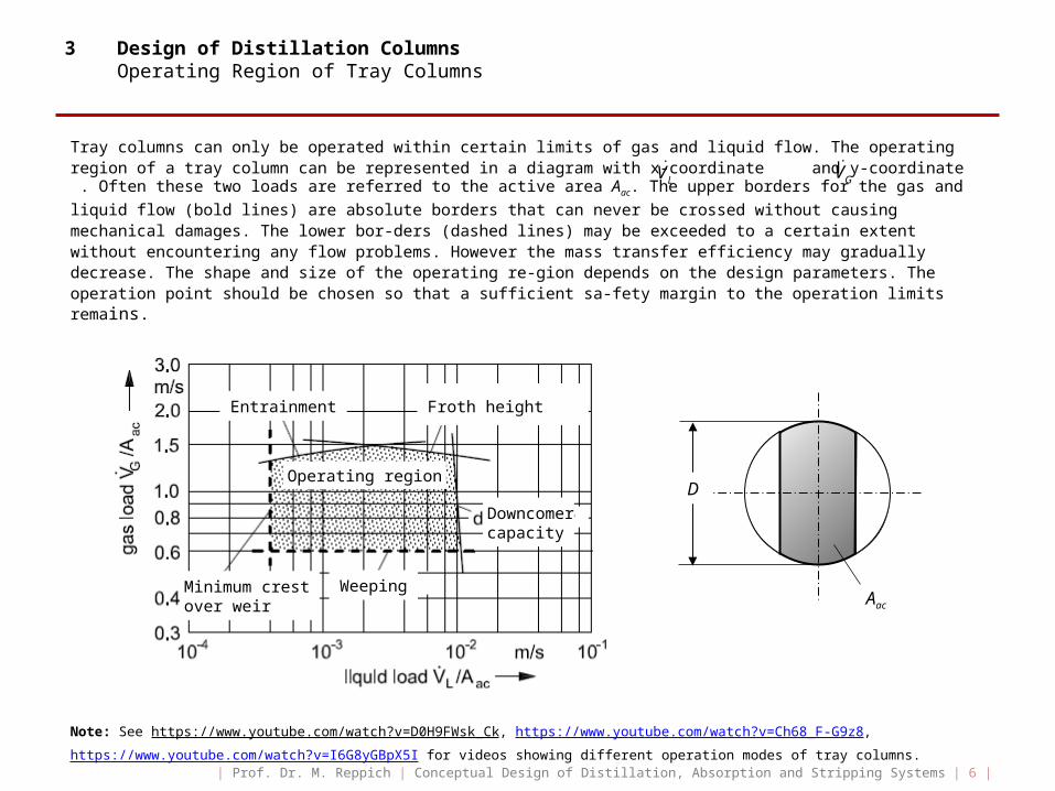
3 Design of Distillation Columns Operating Region of Tray Columns
Tray columns can only be operated within certain limits of gas and liquid flow. The operating region of a tray column can be represented in a diagram with x-coordinate and y-coordinate . Often these two loads are referred to the active area Aac. The upper borders for the gas and liquid flow (bold lines) are
absolute borders that can never be crossed without causing mechanical damages. The lower bor-ders (dashed lines) may be exceeded to a certain extent without encountering any flow problems. However the mass transfer efficiency may gradually decrease. The shape and size of the operating re-gion depends on the design parameters. The operation point should be chosen so that a sufficient sa-fety margin to the operation limits remains.
Note: See https://www.youtube.com/watch?v=D0H9FWsk_Ck , https://www.youtube.com/watch?v=Ch68_F-G9z8 ,
https://www.youtube.com/watch?v=I6G8yGBpX5I for videos showing different operation modes of tray columns.
LV
D
Aac
LV GV
Entrainment Froth height
Downcomercapacity
WeepingMinimum crest over weir
Operating region
| Prof. Dr. M. Reppich | Conceptual Design of Distillation, Absorption and Stripping Systems | 6 |
3 Design of Distillation Columns Operating Region of Tray Columns
As described below the gas and liquid loads has to be kept between a maximum and a minimum value. Therefore, four limitations can be defined:
• at low gas velocities either the gas no longer flows uniformly though all the tray openings (bypassing part of the tray) or the liquid leaks though the tray (weeping)
• both modes of operation should be avoided due to tray efficiency losses because of insufficient degree of mixing of the both phases
• the main factor that affects weeping is the hole diameter (the minimum gas load increases with increasing hole diameter)
• at high gas velocities the gas blows the liquid off the tray in form of fine droplets (entrainment, jet flood)
• the liquid flows no longer countercurrently to the gas, and proper column operation ends
• the maximum feasible gas load depends on system properties (den-sity of gas and liquid, surface tension) as well as on tray design
• entrainment flooding of trays is decisive at very large tray spacings z, for smaller tray spacings z the froth height on the tray sets a lower limitation
Minimum Gas Load:
Maximum Gas Load:
| Prof. Dr. M. Reppich | Conceptual Design of Distillation, Absorption and Stripping Systems | 7 |
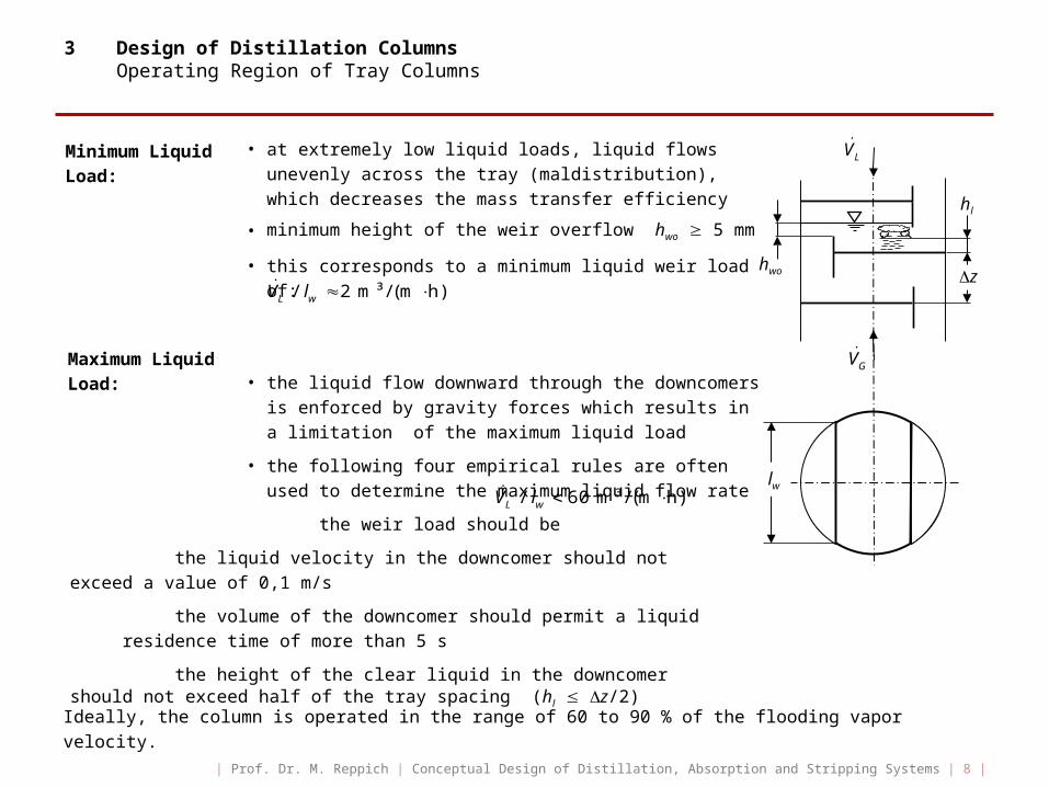
3 Design of Distillation Columns Operating Region of Tray Columns
• at extremely low liquid loads, liquid flows unevenly across the tray (maldistribution), which decreases the mass transfer efficiency
• minimum height of the weir overflow hwo 5 mm
• this corresponds to a minimum liquid weir load of:
• the liquid flow downward through the downcomers is enforced by gravity forces which results in a limitation of the maximum liquid load
• the following four empirical rules are often used to determine the maximum liquid flow rate
the weir load should be
the liquid velocity in the downcomer should not exceed a value of 0,1 m/s
the volume of the downcomer should permit a liquid residence time of more than 5 s
the height of the clear liquid in the downcomer should not exceed half of the tray spacing (hl z/2)
Ideally, the column is operated in the range of 60 to 90 % of the flooding vapor velocity.
Minimum LiquidLoad:
Maximum LiquidLoad:
/ 60 m³ /(m h)L wV l lw
hwo z
GV
LV
/ 2 m³ /(m h)L wV l
hl
| Prof. Dr. M. Reppich | Conceptual Design of Distillation, Absorption and Stripping Systems | 8 |
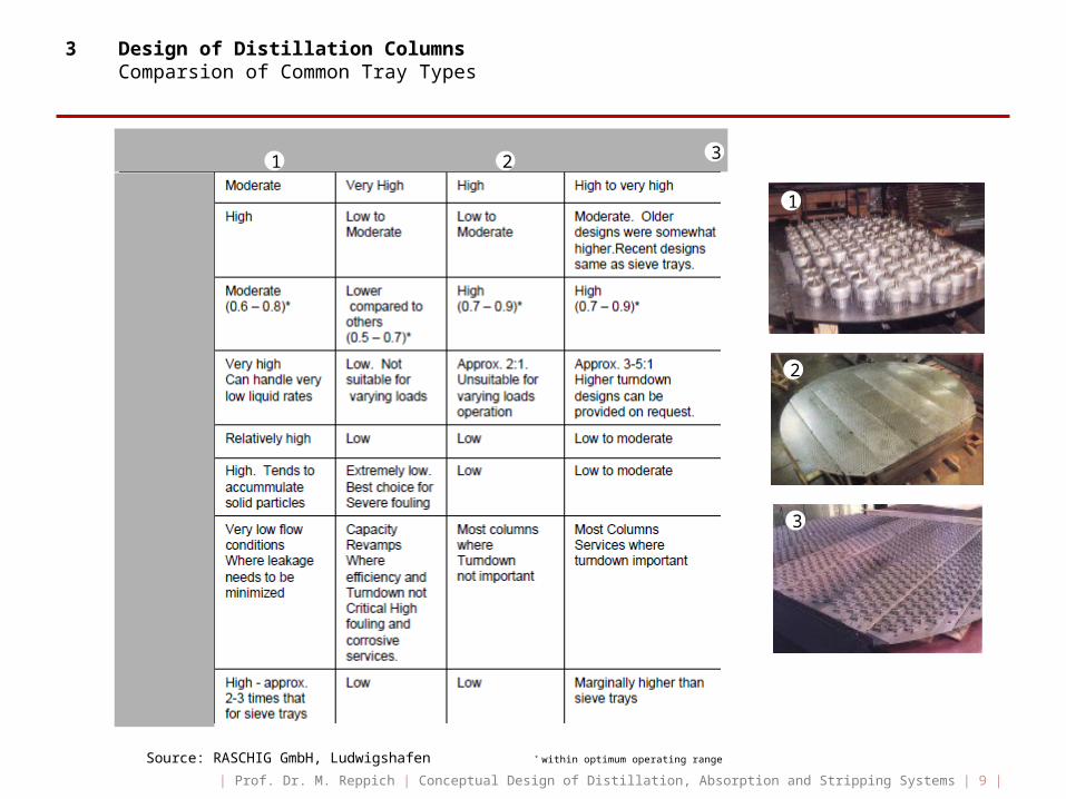
3 Design of Distillation Columns Comparsion of Common Tray Types
Source: RASCHIG GmbH, Ludwigshafen * within optimum operating range
1
2
3
1 2 3
| Prof. Dr. M. Reppich | Conceptual Design of Distillation, Absorption and Stripping Systems | 9 |
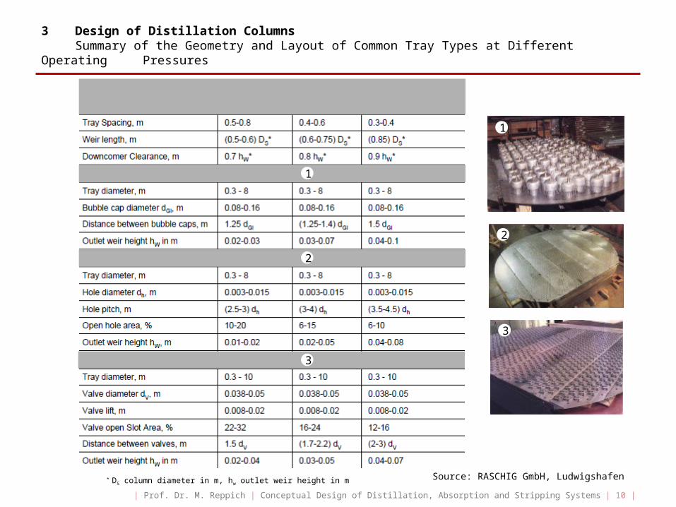
3 Design of Distillation Columns Summary of the Geometry and Layout of Common Tray Types at Different Operating Pressures
* DS column diameter in m, hw outlet weir height in m
2
3
1 2 3
Source: RASCHIG GmbH, Ludwigshafen
1
2
3
1
| Prof. Dr. M. Reppich | Conceptual Design of Distillation, Absorption and Stripping Systems | 10 |
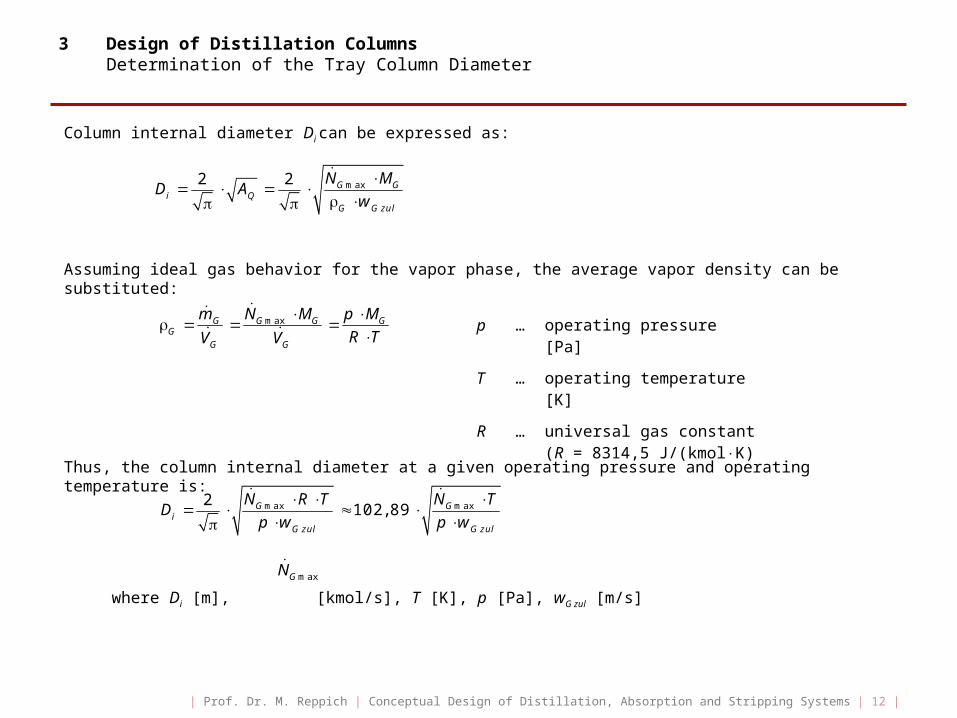
3 Design of Distillation Columns Determination of the Tray Column Diameter
The tower diameter and, consequently, the cross-sectional area of the column must be sufficiently large to handle the gas and liquid rates within the operating region. The diameter of a distillation column is generally controlled by the vapor velocity.
For designing a column the vapor velocity of the inside cross-sectional area of the empty tower is used. The vapor flows vertically upward usually at velocity from 0,5 to 2,5 m/s, and from 3 to 6 m/s in bubble-cup or tunnel tray columns. In contrast, the downflow velocity range of the liquid is from 110-3 to 1510-3 m/s.
The required free cross-sectional area of the column is determined using the maximum vapor volume-tric flow rate during the operation and the allowable vapor velocity referred to the total column cross-sectional area:
2 max max max
4G G G G
Q iG zul G G zul G G zul
V m N MA D
w w w
AQ … free (total) cross-sectional area of the column [m²]
Di … column internal diameter [m]
… maximum vapor volumetric flow rate [m³/s]
wG zul … allowable vapor velocity referred to the area AQ [m/s] (0,5…6 m/s)
… maximum vapor mass flow rate [kg/s]
… maximum vapor molar flow rate [kmol/s]
G … avarage density of the vapor phase [kg/m³]
MG … average molecular weigth of the vapor phase [kg/kmol]
maxGV
maxGm
maxGN
| Prof. Dr. M. Reppich | Conceptual Design of Distillation, Absorption and Stripping Systems | 11 |
3 Design of Distillation Columns Determination of the Tray Column Diameter
Column internal diameter Di can be expressed as:
Assuming ideal gas behavior for the vapor phase, the average vapor density can be substituted:
Thus, the column internal diameter at a given operating pressure and operating temperature is:
where Di [m], [kmol/s], T [K], p [Pa], wG zul [m/s]
max2 2 G G
i QG G zul
N MD A
w
p … operating pressure [Pa]
T … operating temperature [K]
R … universal gas constant(R = 8314,5 J/(kmolK)
maxG G G GG
G G
m N M p MR TV V
max max2
102,89G Gi
G zul G zul
N R T N TD
p w p w
maxGN
| Prof. Dr. M. Reppich | Conceptual Design of Distillation, Absorption and Stripping Systems | 12 |

3 Design of Distillation Columns Determination of the Tray Column Diameter
The allowable vapor velocity referred to the total column cross-sectional area wG zul depends mainly on
the tray type and its geometry, on the liquid load, and on the physical properties of the both phases.
The usual design limit is entrainment flooding, which is caused by excessive carry-up of suspended liquid droplets by rising vapor to the tray above. At low vapor velocity, a droplet settles out; at high vapor velocity, it is entrained. At flooding velocity wG max, the droplet is suspended such that the vec-tor sum of the buoyant force FA, drag force FW, and gravitational force FG acting on the droplet will be zero.
From the balance of forces at a liquid doplet and a safety margin (fraction of flooding) results the allowable vapor velocity wG zul referred to the total column cross-sectional area:
max 0,7 ac L GG zul G V
Q G
Aw f w k
A
f … fraction of flooding, e.g. f=0,7
kV … capacity parameter of Souders/Brown [m/s]
Aac … active area of a tray [m²]
AQ … total column cross-sectional area [m²]
L … liquid density [kg/m³]
G … vapor density [kg/m³]
z
maxGw
Lw
FA
FW
FG
Two-phaseLayer
z … tray spacing … liquid surface tension
| Prof. Dr. M. Reppich | Conceptual Design of Distillation, Absorption and Stripping Systems | 13 |

3 Design of Distillation Columns Pressure Drop in Tray Columns
Generally, the column pressure drop should be as low as possible because
• obtaining the number of theoretical trays using the McCabe-Thiele graphical method assumes that the pressure is constant over the whole column
• low pressure drop leads to a reduced energy requirement and to a heat supplied by the reboiler at the bottom at a lower boiling temperature level.
Pressure loss of the vapor significantly depends on both gas and liquid load. The total column pressure drop is the sum of the hydrostatic pressure loss caused by the clear liquid holdup on the trays, the pressure drop due to the friction for vapor flow through the openings in the trays, and a loss due to the formation of bubbles by the gas:
The first term in the equation above accounts for the liquid head on a tray, the second term refers to the dry pressure loss of the tray, the third term is small compared with pcol and is usually negligible.
Due to the numerous variables such as tray geometry, physical properties of vapor and liquid, gas and liquid loads, operating pressure, etc. a general equation to calculate the columns pressure drop has not yet been developed. In most cases, the pressure drop must be found depending on the tray type experimentally.
col st dynp p p p
pcol … total column pressure drop [Pa]
pst … hydrostatic pressure drop of clear liquid [Pa]
pdyn … pressure drop due to vapor flow resistance [Pa]
p … pressure drop due to surface tension [Pa]
| Prof. Dr. M. Reppich | Conceptual Design of Distillation, Absorption and Stripping Systems | 14 |
3 Design of Distillation Columns Pressure Drop in Tray Columns
The hydrostatic pressure drop of liquid pst depends on the mass of the clear liquid inside the column,
as given by:
For tray columns the hydrostatic pressure drop is given by the sum of the pressure drops across the trays:
(1 )st eff S S eff L Sp N g h N g h
mL … total mass of the liquid in the column [kg]
g … gravitational constant g = 9,81 m/s²
AQ … total cross-sectional area of the column [m²]
Lst
Q
m gp
A
Neff … number of actual trays []
S … average density of the two-phase layer [kg/m³]
L … density of clear liquid [kg/m³]
… relative gas/vapor fraction in the two-phase layer []
hS … average heigth of the two-phase layer [m]
| Prof. Dr. M. Reppich | Conceptual Design of Distillation, Absorption and Stripping Systems | 15 |
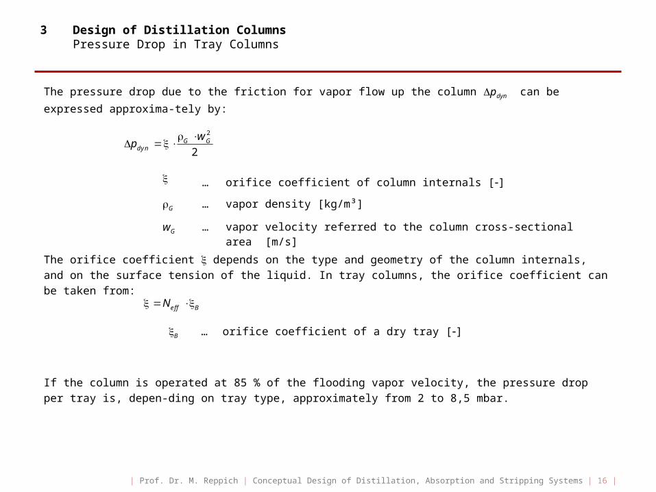
3 Design of Distillation Columns Pressure Drop in Tray Columns
The pressure drop due to the friction for vapor flow up the column pdyn can be expressed approxima-
tely by:
The orifice coefficient depends on the type and geometry of the column internals, and on the surface tension of the liquid. In tray columns, the orifice coefficient can be taken from:
If the column is operated at 85 % of the flooding vapor velocity, the pressure drop per tray is, depen-ding on tray type, approximately from 2 to 8,5 mbar.
… orifice coefficient of column internals []
G … vapor density [kg/m³]
wG … vapor velocity referred to the column cross-sectional area [m/s]
2
2G G
dyn
wp
eff BN
B … orifice coefficient of a dry tray []
| Prof. Dr. M. Reppich | Conceptual Design of Distillation, Absorption and Stripping Systems | 16 |
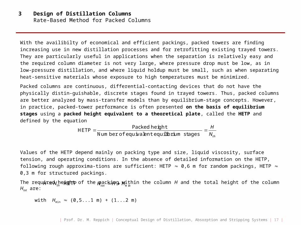
3 Design of Distillation Columns Rate-Based Method for Packed Columns
With the availibilty of economical and efficient packings, packed towers are finding increasing use in new distillation processes and for retrofitting existing trayed towers. They are particularly useful in applications when the separation is relatively easy and the required column diameter is not very large, where pressure drop must be low, as in low-pressure distillation, and where liquid holdup must be small, such as when separating heat-sensitive materials whose exposure to high temperatures must be minimized.
Packed columns are continuous, differential-contacting devices that do not have the physically distin-guishable, discrete stages found in trayed towers. Thus, packed columns are better analyzed by mass-transfer models than by equilibrium-stage concepts. However, in practice, packed-tower performance is often presented on the basis of equilibrium stages using a packed height equivalent to a theoretical plate, called the HETP and defined by the equation
Values of the HETP depend mainly on packing type and size, liquid viscosity, surface tension, and operating conditions. In the absence of detailed information on the HETP, following rough approxima-tions are sufficient: HETP 0,6 m for random packings, HETP 0,3 m for structured packings.
The required height of the packing within the column H and the total height of the column Htot are:
with Hmin (0,5...1 m) + (1...2 m)
Packed heightHETP
Number of equivalent equilibrium stages th
HN
HETPthH N mintotH H H
| Prof. Dr. M. Reppich | Conceptual Design of Distillation, Absorption and Stripping Systems | 17 |

3 Design of Distillation Columns HETP Estimation for Random and Structured Packings
For rough estimates of the HETP the following relations can be used (all values are in ft, 1 ft = 0,3048 m)
1. Random packings of second and third generation with low-viscosity liquids
dP … nominal packing diameter [in] (1 in = 25,4 mm)
2. Structured packings at low-to-modarate pressures with low-viscosity liquids
a … packing surface area per packed volume [ft²/ft³]
3. Distillation with viscous liquid
4. Vacuum service
5. Structured packings at high pressures
6. Small-diameter columns with internal diameter Di < 2 ft
HETP 1,5 Pd
100
HETP 0,333a
HETP 5 6 ft
HETP 1,5 0,5Pd
100
HETP 0,333a
HETP , but HETP 1 ftiD
| Prof. Dr. M. Reppich | Conceptual Design of Distillation, Absorption and Stripping Systems | 18 |

3 Design of Distillation Columns Characteristics of Random Packings
Sources: W. D. Seider et al.: Product and Process Design Principles. 3. Aufl., John Wiley, Hoboken 2010; Vereinigte Füllkörper-Fabriken GmbH & Co. KG., Ransbach-Baumbach
Type Packing Material Nominal Diameter
dP [in]
Packing Factor FP [ft²/ft³]
Raschig rings Ceramic 1,02,03,0
1575833
Raschig rings Metal 1,02,03,0
1657140
Intalox saddles Ceramic 1,02,03,0
923015
Intalox saddles Plastic 1,02,0
3625
Pall rings Metal 1,01,52,03,5
56292716
Pall rings Plastic 1,02,03,5
532515
| Prof. Dr. M. Reppich | Conceptual Design of Distillation, Absorption and Stripping Systems | 19 |
3 Design of Distillation Columns Characteristics of Random and Structured Packings
Source: E. J. Henley et al.: Separation Process Principles. 3. Aufl., John Wiley, Hoboken 2011
Packing Material Size [mm]
Packing Factor FP
[ft²/ft³]
Mass-transfer Surface Area per Unit Volume
a [m²/m³]
Void Fraction [-]
Random Packings
Hiflow rings CeramicMetalPlastic
505050
291620
89,7 92,3117,1
0,8090,9770,924
Nor-Pac rings PlasticPlasticPlastic
503515
1421
86,8141,8311,4
0,9470,9440,918
Tellerettes Plastic 25 40 190,0 0,930
Top-Pak rings Aluminium 50 105,5 0,956
VSP rings MetalMetal
5025
104,6199,6
0,9800,975
Structured Packings
EuroformGempakKoch-SulzerKoch-SulzerMellapakMontzMontzMontzMontzMontz
PlasticMetalMetalMetalPlasticMetalMetalMetalPlasticPlastic
PN-110A2 T-304CYBX250 YB1-100B1-200B1-300C1-200C2-200
702122
33
110,0202,0
250,0100,0200,0300,0200,0200,0
0,9360,977
0,9700,9870,9790,9300,9540,900
| Prof. Dr. M. Reppich | Conceptual Design of Distillation, Absorption and Stripping Systems | 20 |
3 Design of Distillation Columns Determination of the Packed Column Diameter
The column diameter is determined so as to safely avoid flooding and to ensure that pressure drop is below 1,2 kPa/m of packed height. At the flooding point, the pressure drop increases infinitely with increasing vapor velocity. The internal column diameter Di is based again on a fraction f of flooding velocity wG max by:
f … fraction of flooding 0,65 < f < 0,9 (f 0,7)
The generalized correlation of Leva gives reasonable estimates of the flooding gas velocity wG max [ft/s]:
and
with
packing factor [ft²/ft³] (usually a … packing surface area per packed determined experimentally) volume [m²/m³]
g … gravitational constant … void fraction [m³/m³, %, -] (g = 32,174 ft/s²)
… avarage density of the vapor phase [kg/m³]
… average density of water [kg/m³] ( = 999,5 kg/m³ at 20 °C, 1 bar)
The above regression model for the dimensionless flooding velocity factor Y = f (FLG) is valid for
0,01 Y 10.
GLLG
G L
mF
m
3P
aF
max max
max
2 2G G G Gi
G G zul G G
N M N MD
w f w
2
2max
GPG
L H O
FY w F F
g
2 3exp 3,7121 1,0371 ln 0,1501 ln 0,007544 lnLG LG LGY F F F
2L H O2L H O
G
| Prof. Dr. M. Reppich | Conceptual Design of Distillation, Absorption and Stripping Systems | 21 |
3 Design of Distillation Columns Determination of the Packed Column Diameter
The functions F and F are corrections for liquid properties given by:
… average density of water [kg/m³] ( = 999,5 kg/m³ at 20 °C, 1 bar)
L … average density of liquid [kg/m³]
L … average dynamic viscosity of liquid [cP]
For a certain value of the flow parameter FLG can firstly be calculated the dimensionless factor Y, and the superficial gas velocity at flooding wG max = f (Y) is then estimated for a given packing type and size (FP = f (a, )) and the correction functions F and F.
Finally, using the allowable vapor velocity wG zul, the internal diameter of the distillation column Di can
be determined. The tower inside diameter should be at least 10 times the nominal packing diameter and preferably closer to 30 times,
dP … nominal packing diameter [mm] .
Under these conditions, the negative effect of maldistribution on mass-transfer efficiency is minimised. Therefore, the column diameter may need to be adjusted accordingly.
2 2 2
2
0,8787 2,6776 0,6313 , valid for 0,65 1, 4L H O L H O L H O
L L L
F
2L H O2L H O
0,190,96 , valid for 0,3 cP 20 cPL LF
10...30i PD d
| Prof. Dr. M. Reppich | Conceptual Design of Distillation, Absorption and Stripping Systems | 22 |

3 Design of Distillation Columns Pressure drop in Packed Columns
An estimation of pressure drop in Pa/m can be made by using the generalized pressure drop correla-tion for packed beds according to Sherwood et al. and Leva:
… liquid flow rate [kg/s]
… gas flow rate [kg/s]
L … liquid density [kg/m³]
G … gas density [kg/m³]
FP … packing factor [ft²/ft³]
wG … gas velocity [m/s], wG = f wG max
L … liquid viscosity [Pas]
The flooding curve in the above figure corresponds to a pressure drop of 1200 Pa/m of packed height and can be accurately described by the polynomial regression:
GLLG
G L
mF
m
2 0,1GP G L
L G
Y F w
Lm
Gm
2exp 3,5021 1,028 ln 0,11093 lnFlooding LG LGY F F
ã J. Benítez: Principles and Modern Applications of Mass Transfer Operations. 2. Aufl., John Wiley, Hoboken 2009
FLG
Y‘
| Prof. Dr. M. Reppich | Conceptual Design of Distillation, Absorption and Stripping Systems | 23 |

3 Design of Distillation Columns Charts for the Design of Random-Packed Columns: HETP Estimation INTALOX® Metal Tower Packing (IMTP®)
Source: Koch-Glitsch, LP, Wichita
S G zul G
GS G zul
L G
F w
C w
| Prof. Dr. M. Reppich | Conceptual Design of Distillation, Absorption and Stripping Systems | 24 |

3 Design of Distillation Columns Charts for the Design of Random-Packed Columns: Estimation of Pressure Drop INTALOX® Metal Tower Packing (IMTP®)
Source: Koch-Glitsch, LP, Wichita
| Prof. Dr. M. Reppich | Conceptual Design of Distillation, Absorption and Stripping Systems | 25 |
3 Design of Distillation Columns Summary of Distillation Column Design
Concept of equilibrium stages: determination of the number of theoretical stages Nth
• McCabe-Thiele graphical equilibrium-stage method• Kremser equation (analytically, assuming straight equilibrium and operation lines absorption/
stripping)
Estimation of the actual number of contacting trays Neff applying an overall column efficiency EOV:
0,1 EOV 0,9
Estimation of HETP depending on packing type and size, liquid viscosity, and surface tension:
Height of the actual equipment:
Internal Column Diameter:
Vapor-side pressure drop:
GPDC charts, correlations
0,3 0,9 m for random packingsHETP
0,2 0,7 m for structured packings
theff
OV
NN
E
minHETPtot thH N H mintot effH N z H min0, 45 0,6 m; 3z H z min 1,5 3 mH
maxwith ; 0,65 0,9G zul Gw f w f
max2 G
iG G zul
G MD
w
f (tray type)colp f (packing type)colp
Distillation/Absorption/Stripping
Tray Columns (sieve, valve, bubble-cup trays)
Random-/Structured-Packed Columns
stagewise contact between the phases continuous contact between the phases
| Prof. Dr. M. Reppich | Conceptual Design of Distillation, Absorption and Stripping Systems | 26 |
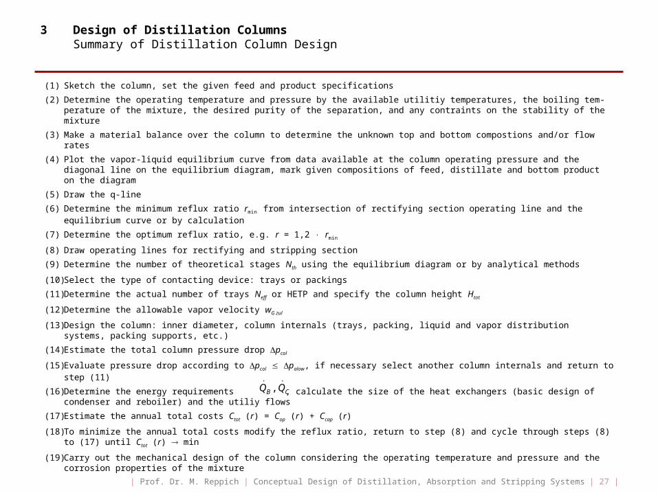
3 Design of Distillation Columns Summary of Distillation Column Design
(1) Sketch the column, set the given feed and product specifications
(2) Determine the operating temperature and pressure by the available utilitiy temperatures, the boiling tem-perature of the mixture, the desired purity of the separation, and any contraints on the stability of the mixture
(3) Make a material balance over the column to determine the unknown top and bottom compostions and/or flow rates
(4) Plot the vapor-liquid equilibrium curve from data available at the column operating pressure and the diagonal line on the equilibrium diagram, mark given compositions of feed, distillate and bottom product on the diagram
(5) Draw the q-line
(6) Determine the minimum reflux ratio rmin from intersection of rectifying section operating line and the equilibrium curve or by calculation
(7) Determine the optimum reflux ratio, e.g. r = 1,2 rmin
(8) Draw operating lines for rectifying and stripping section
(9) Determine the number of theoretical stages Nth using the equilibrium diagram or by analytical methods
(10) Select the type of contacting device: trays or packings
(11) Determine the actual number of trays Neff or HETP and specify the column height Htot
(12) Determine the allowable vapor velocity wG zul
(13) Design the column: inner diameter, column internals (trays, packing, liquid and vapor distribution systems, packing supports, etc.)
(14) Estimate the total column pressure drop pcol
(15) Evaluate pressure drop according to pcol palow, if necessary select another column internals and return to step (11)
(16) Determine the energy requirements , calculate the size of the heat exchangers (basic design of condenser and reboiler) and the utiliy flows
(17) Estimate the annual total costs Ctot (r) = Cop (r) + Ccap (r)
(18) To minimize the annual total costs modify the reflux ratio, return to step (8) and cycle through steps (8) to (17) until Ctot (r) min
(19) Carry out the mechanical design of the column considering the operating temperature and pressure and the corrosion properties of the mixture
,B CQ Q
| Prof. Dr. M. Reppich | Conceptual Design of Distillation, Absorption and Stripping Systems | 27 |
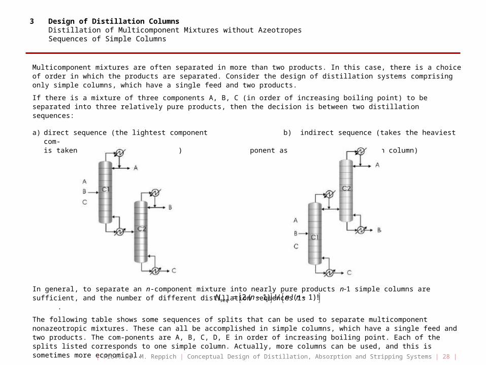
3 Design of Distillation Columns Distillation of Multicomponent Mixtures without AzeotropesSequences of Simple Columns
Multicomponent mixtures are often separated in more than two products. In this case, there is a choice of order in which the products are separated. Consider the design of distillation systems comprising only simple columns, which have a single feed and two products.
If there is a mixture of three components A, B, C (in order of increasing boiling point) to be separated into three relatively pure products, then the decision is between two distillation sequences:
a) direct sequence (the lightest component b) indirect sequence (takes the heaviest com-is taken overhead in each column) ponent as bottom product in each column)
In general, to separate an n-component mixture into nearly pure products n1 simple columns are sufficient, and the number of different distillation sequences is .
The following table shows some sequences of splits that can be used to separate multicomponent nonazeotropic mixtures. These can all be accomplished in simple columns, which have a single feed and two products. The com-ponents are A, B, C, D, E in order of increasing boiling point. Each of the splits listed corresponds to one simple column. Actually, more columns can be used, and this is sometimes more economical.
2( 1) !/ !( 1)!seqN n n n
| Prof. Dr. M. Reppich | Conceptual Design of Distillation, Absorption and Stripping Systems | 28 |
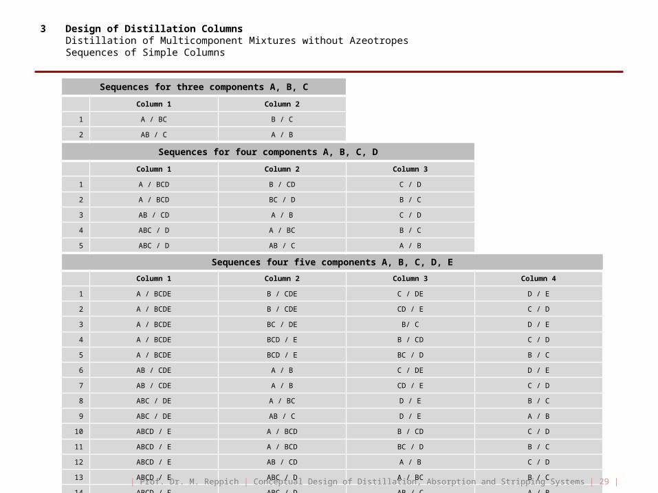
3 Design of Distillation Columns Distillation of Multicomponent Mixtures without AzeotropesSequences of Simple Columns
Sequences for three components A, B, C
Column 1 Column 2
1 A / BC B / C
2 AB / C A / B
Sequences for four components A, B, C, D
Column 1 Column 2 Column 3
1 A / BCD B / CD C / D
2 A / BCD BC / D B / C
3 AB / CD A / B C / D
4 ABC / D A / BC B / C
5 ABC / D AB / C A / B
Sequences four five components A, B, C, D, E
Column 1 Column 2 Column 3 Column 4
1 A / BCDE B / CDE C / DE D / E
2 A / BCDE B / CDE CD / E C / D
3 A / BCDE BC / DE B/ C D / E
4 A / BCDE BCD / E B / CD C / D
5 A / BCDE BCD / E BC / D B / C
6 AB / CDE A / B C / DE D / E
7 AB / CDE A / B CD / E C / D
8 ABC / DE A / BC D / E B / C
9 ABC / DE AB / C D / E A / B
10 ABCD / E A / BCD B / CD C / D
11 ABCD / E A / BCD BC / D B / C
12 ABCD / E AB / CD A / B C / D
13 ABCD / E ABC / D A / BC B / C
14 ABCD / E ABC / D AB / C A / B
| Prof. Dr. M. Reppich | Conceptual Design of Distillation, Absorption and Stripping Systems | 29 |
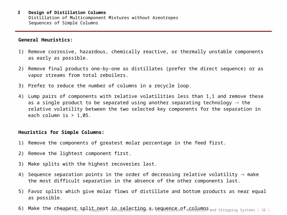
3 Design of Distillation Columns Distillation of Multicomponent Mixtures without AzeotropesSequences of Simple Columns
General Heuristics:
1) Remove corrosive, hazardous, chemically reactive, or thermally unstable components as early as possible.
2) Remove final products one-by-one as distillates (prefer the direct sequence) or as vapor streams from total reboilers.
3) Prefer to reduce the number of columns in a recycle loop.
4) Lump pairs of components with relative volatilities less than 1,1 and remove these as a single product to be separated using another separating technology the relative volatility between the two selected key components for the separation in each column is > 1,05.
Heuristics for Simple Columns:
1) Remove the components of greatest molar percentage in the feed first.
2) Remove the lightest component first.
3) Make splits with the highest recoveries last.
4) Sequence separation points in the order of decreasing relative volatility make the most difficult separation in the absence of the other components last.
5) Favor splits which give molar flows of distillate and bottom products as near equal as possible.
6) Make the cheapest split next in selecting a sequence of columns.
| Prof. Dr. M. Reppich | Conceptual Design of Distillation, Absorption and Stripping Systems | 30 |


![[PPT]PowerPoint-Präsentation - Hochschule Augsburgschaafa/Korrektorat_Reppich/P11.pptx · Web view3 Design ofDistillation ColumnsDetermination oftheNumberofActual Stages In the previous](https://img.pdfslide.us/doc/110x75/5acd2d8c7f8b9aad468d9d29/pptpowerpoint-prsentation-hochschule-schaafakorrektoratreppichp11pptxweb.jpg)