Embed Size (px)
Citation preview
WANNER ENGINEERING, INC.
1204 Chestnut Avenue, Minneapolis, MN 55403 TEL: (612) 332-5681 FAX: (612) 332-6937 TOLL-FREE FAX [US only]: (800) 332-6812
www.epmpump.com email: [email protected]
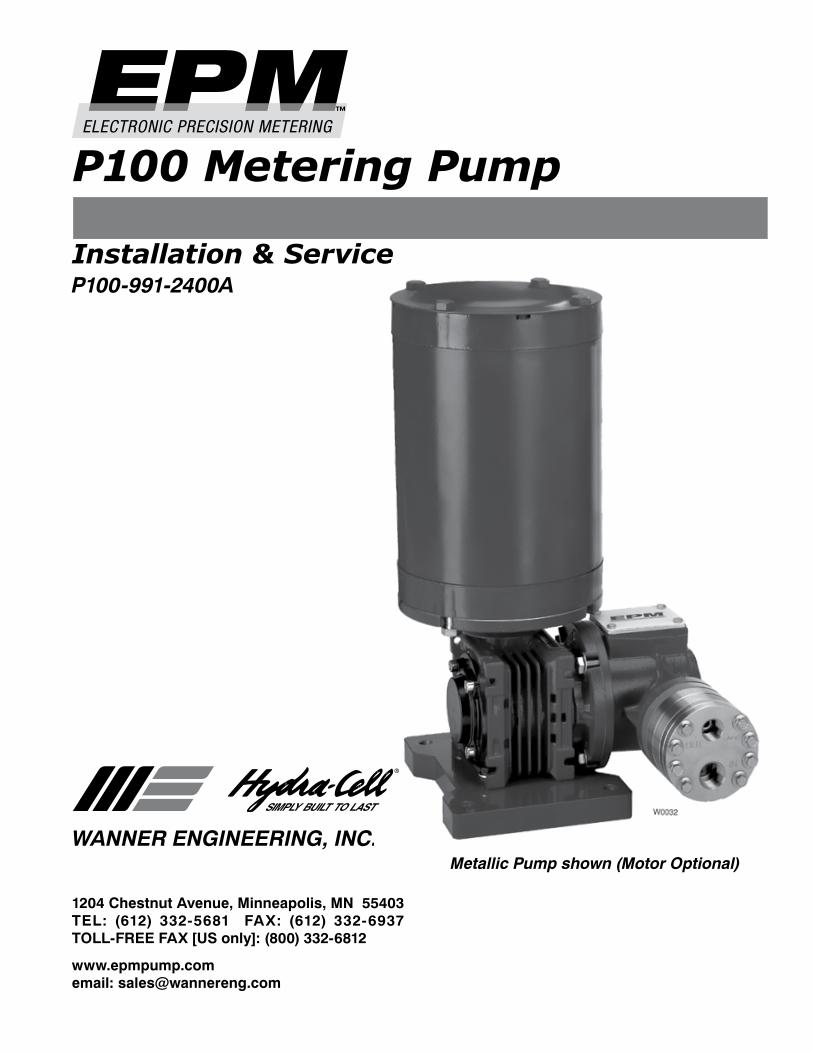
Installation & ServiceP100-991-2400A
P100 Metering Pump
Metallic Pump shown (Motor Optional)
� P100-991-�400A
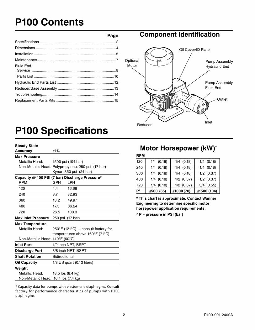
Motor Horsepower (kW)*
RPM
1�0 1/4 (0.18) 1/4 (0.18) 1/4 (0.18)
�40 1/4 (0.18) 1/4 (0.18) 1/4 (0.18)
360 1/4 (0.18) 1/4 (0.18) 1/� (0.37)
480 1/4 (0.18) 1/� (0.37) 1/� (0.37)
7�0 1/4 (0.18) 1/� (0.37) 3/4 (0.55)
P# ≤500 (35) ≤1000(70) ≤1500(104)
* This chart is approximate. Contact Wanner Engineering to determine specific motor horsepower application requirements.# P = pressure in PSI (bar)
Steady State Accuracy ±1%
Max Pressure MetallicHead: 1500psi(104bar) Non-MetallicHead:Polypropylene:�50psi(17bar) Kynar:350psi(�4bar)
Capacity @ 100 PSI (7 bar) Discharge Pressure* RPM GPH LPH
1�0 4.4 16.66
�40 8.7 3�.93
360 13.� 49.97
480 17.5 66.�4
7�0 �6.5 100.3
Max Inlet Pressure �50psi(17bar)
Max Temperature MetallicHead: �50°F(1�1°C)–consultfactoryfor temperaturesabove160°F(71°C) Non-MetallicHead:140°F(60°C)
Inlet Port 1/�inchNPT,BSPT
Discharge Port 3/8inchNPT,BSPT
Shaft Rotation Bidirectional
Oil Capacity 1/8USquart(0.1�liters)
Weight MetallicHead: 18.5lbs(8.4kg) Non-MetallicHead:16.4lbs(7.4kg)
P100 Specifications
P100 Contents PageSpecifications..........................................................................�
Dimensions.............................................................................4
Installation...............................................................................5
Maintenance............................................................................7
FluidEndService.................................................................................8
PartsList.............................................................................10
HydraulicEndPartsList.......................................................1�
Reducer/BaseAssembly......................................................13
Troubleshooting.....................................................................14
ReplacementPartsKits........................................................15
* Capacity data for pumps with elastomeric diaphragms. Consult factory for performance characteristics of pumps with PTFE diaphragms.
Component Identification
W0240
OilCover/IDPlate
OptionalMotor
Outlet
ReducerInlet
PumpAssemblyFluidEnd
PumpAssemblyHydraulicEnd
3 P100-991-�400A
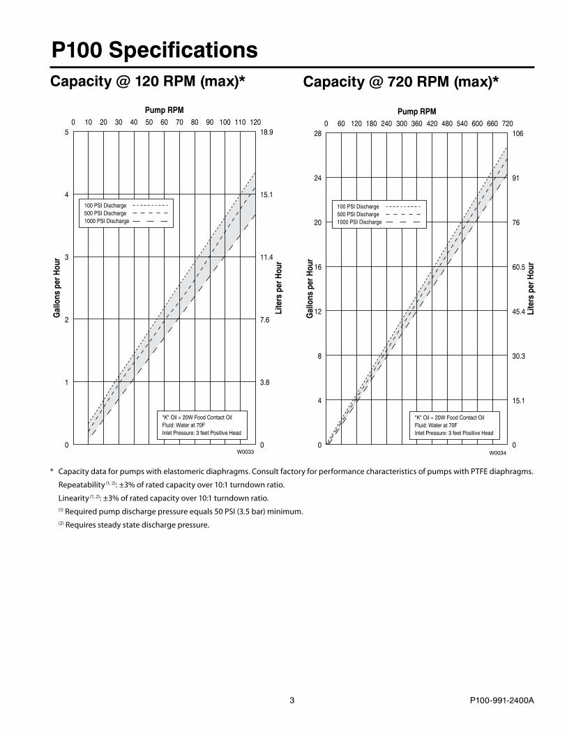
Capacity @ 120 RPM (max)*
P100 SpecificationsCapacity @ 720 RPM (max)*
* Capacity data for pumps with elastomeric diaphragms. Consult factory for performance characteristics of pumps with PTFE diaphragms.
Repeatability (1, 2): ±3% of rated capacity over 10:1 turndown ratio.
Linearity (1, 2): ±3% of rated capacity over 10:1 turndown ratio. (1) Required pump discharge pressure equals 50 PSI (3.5 bar) minimum. (2) Requires steady state discharge pressure.
Pump RPM0 10 20 30 40 50 60 70 80 90 100 110 120
Gal
lons
per
Hou
r
Lite
rs p
er H
our
5
4
3
2
1
0
18.9
15.1
11.4
7.6
3.8
0
100 PSI Discharge500 PSI Discharge1000 PSI Discharge
"K" Oil = 20W Food Contact OilFluid: Water at 70FInlet Pressure: 3 feet Positive Head
W0033
100 PSI Discharge500 PSI Discharge1000 PSI Discharge
"K" Oil = 20W Food Contact OilFluid: Water at 70FInlet Pressure: 3 feet Positive Head
Pump RPM0 60 120 180 240 300 360 420 480 540 600 660 720
Gal
lons
per
Hou
r
Lite
rs p
er H
our
28
0
106
24 91
20 76
16 60.5
12 45.4
8 30.3
4 15.1
0W0034
4 P100-991-�400A
1/2" NPT or1/2" BSPT
3/8" NPT or3/8" BSPT
OUT
IN
5.75(146.1)
7.27(184.7)
8.61(218.7)
9.03(229.4)
Ø0.41(10.4) (4X)
5.65(143.5)
4.50(114.3)
0.78(19.8)
5.90(149.9)
Ø6.50(165.1)
NEMA 56C Ø0.625(15.88)
Square Key0.187(4.75)
NEMA 56C FlangePilotØ4.500
(114.3)
Bolt CircleØ5.875(149.2)
10.36(263.1)
0.27(6.9)
7.27(184.7)
11.55(293.4)
9.07(230.4)
5.65(143.5)
7.21(183.1)
8.65(219.7)
2.10(53.3)
3.47(88.1)
1
1Note:Worm Gear Reducer availablein the following ratios: 5:1, 7.5:1,10:1, 15:1, 20:1, 25:1, 30:1, 40:1,50:1, 60:1, 80:1, 100:1. W0036
1/2" NPT or1/2" BSPT
3/8" NPT or3/8" BSPT
OUT
IN
5.75(146.1)
7.27(184.7)
8.61(218.7)
9.03(229.4)
Ø0.41(10.4) (4X)
5.65(143.5)
4.50(114.3)
0.78(19.8)
5.90(149.9)
Ø6.50(165.1)
NEMA 56C Ø0.625(15.88)
Square Key0.187(4.75)
NEMA 56C FlangePilotØ4.500
(114.3)
Bolt CircleØ5.875(149.2)
10.11(256.8)
0.27(6.9)
7.27(184.7)
11.30(287)
9.07(230.4)
5.65(143.5)
7.21(183.1)
8.65(219.7)
2.10(53.3)
3.47(88.1)
1
1Note:Worm Gear Reducer availablein the following ratios: 5:1, 7.5:1,10:1, 15:1, 20:1, 25:1, 30:1, 40:1,50:1, 60:1, 80:1, 100:1. W0035
P100 DimensionsP100 Models with Metallic Pumping Head
P100 Models with Non-Metallic Pump Head
316StainlessSteel
Hastelloy®C
Kynar
Polypropylene
Inches(mm)
5 P100-991-�400A
P100 InstallationLocationNOTE: The numbers in parentheses are Reference Numbers located in the Parts List exploded views of this manual.
Locatethepumpasclosetothesupplysourceaspossible.
Installitinalightedcleanspacewhereitwillbeeasytoinspectandmaintain.
Motor and ControllerThePSeriespumpshaftcanrotateineitherdirection,thereforedirectionofmotorshaftrotationisnotcritical.
AccessoriesConsultinstallationdrawingbelowfortypicalprecisionmeteringfluidsystemcomponents.ContactWannerEngineeringorthedistributorinyourareaformoredetails.
Important PrecautionsAdequate Fluid Supply. To avoid cavitation andprematurepumpfailure,besurethatthepumpwillhaveanadequatefluidsupplyandthattheinletlinewillnotbeobstructed.SeeInlet Piping onpage6.
Positive Displacement.Thisisapositive-displacementpump.Toavoidseveresystemdamageifthedischargelineeverbecomesblocked,installareliefvalvedownstreamfromthepump.SeeDischarge Pipingonpage6.
Safety Guards.Followallcodesandregulationsregardinginstallationandoperationofthepumpingsystem.
Shut-Off Valves.Neverinstallshut-offvalvesbetweenthe pump and discharge pressure regulator, or in theregulatorbypassline.
ConsulttheFactoryforthefollowingsituations:
• Extreme temperature applications (above 160°F orbelow40°F)
• Pressurefeedingofpumps• Viscousorabrasivefluidapplications• Chemicalcompatibilityproblems• Hotambienttemperatures(above110°F)
1000
200
400 600
800
0
ChemicalContainer
CalibrationCylinderInjection
Valve
DrainValve Shut Off
Valve
PulsationDampener
IsolatingBall Valves
Y-Strainer
Optional PressureRelief Piping
PressureRelief Valve
P-SeriesPump
PressureGauge
Back Pressure / Priming Valve
W0004
6 P100-991-�400A
P100 InstallationInlet PipingProvideforpermanentortemporaryinstallationofacompoundpressure gauge to monitor the inlet pressure. To maintainmaximumflow,thepumpinletshouldbeunderfloodedsuctionconditionsatalltimes.Do not supply more than one pump from the same inlet line.
Supply TankUseasupplytankthatislargeenoughtoprovidetimeforanytrappedairinthefluidtoescape.Thetanksizeshouldbeatleasttwicethemaximumpumpflowrate.
Install a separate inlet line from the supply tank to eachpump.
Placeacoveroverthesupplytank,topreventforeignobjectsfromfallingintoit.
Hose Sizing and RoutingTominimizeaccelerationheadandfrictional losses,sizethesuctionlineat leastonesizelargerthanthepumpinlet,andkeepthesuctionlineasshortanddirectaspossible.Recommendations:
• Keepinletlineslessthan3ft.(1m)long• Useatleast5/8”(16mm)I.D.inlethose• Minimizefittings(elbows,valves,tees,etc.)
Inlet Piping (Pressure Feed)Provideforpermanentortemporaryinstallationofapressuregaugetomonitortheinletpressure.Pressureatthepumpinletshould not exceed �50 psi (17.3 bar). For higher pressuresinstallapressurereducingvalve.Do not supply more than one pump from the same inlet line.
Note: System back pressure must exceed the pump inlet pressure by at least 15 psi (1 bar) in order to prevent flow thru.
Discharge PipingHose and RoutingUsetheshortest,most-directrouteforthedischargeline.
Selectpipeorhosewithaworking pressure ratingofatleast1.5timesthemaximumsystempressure.EXAMPLE:Selecta1500psi(103bar)W.P.ratedhoseforasystemtobeoperatedat1000psi(69bar)gaugepressure.
Supportthepumpandpipingindependently.
Pressure RegulationInstall a pressure relief valve in the discharge line.Bypasspressuremustnotexceedthepressurelimitofthepump.
Sizethevalvesothat,whenfullyopen,itwillbelargeenoughtorelievethefullcapacityofthepumpwithoutoverpressurizingthesystem.
Locatethevalveasclosetothepumpaspossibleandaheadofanyothervalves.
Adjustthepressurereliefvalvetonomorethan10%overthemaximumworkingpressureofthesystem.Donotexceedthemanufacturer’spressureratingforthepumporvalve.
Routethebypasslinetothesupplytank.
CAUTION: Never install shutoff valves in the bypass line or between the pump and pressure regulator or relief valve.
Provideforpermanentortemporaryinstallationofapressuregaugetomonitorthedischargepressureatthepump.
Minimum Discharge PressureTo ensure proper capacity control, a minimum dischargepressureof50psi(3.5bar)isrequired.
7 P100-991-�400A
P100 Installation
Calibration ProcedureEachindividualmeteringpumpputintoservicemustbecalibratedinordertoaccuratelydeterminerequiredpumpspeedtoachievethedesiredflow.Thecapacitycurvesshownonpage3representatypicalpump;individualpumpsmayvaryslightlyfromthesecurves.Inordertoachievethebestpossibleresults,performcalibrationunderactualprocessconditions.Followthesesteps:
1. Runthepumpfor�0minutesatactualprocessconditions.Iftheprocesssystemcannotbeused,circulatebacktothesupplytankthroughapressurereliefvalve(seeInstallationdrawingonpage5).Ifrequiredsystempressureislessthan50PSI(3.5bar)abackpressurevalvemustbeinstalledandsettoproduceaminimumof50PSI(3.5bar)pressureatthepumphead.
�. Determine maximum pump speed required for all systemconditionsthatneedtobesatisfied.Measurepumpdeliveryatthismaximumspeedusingyoursystemcalibrationcylinder,flowmeter,orsomeothermeans.Thisisconsideredtobethe“ratedcapacity”foryourparticularmeteringpump.
3. Measurepumpdeliveryat75%,50%,�5%,and10%of themaximum speed just determined. Let the pump run for 5minutes at each speed setting before taking the capacitymeasurement.
4. Plot thesevaluesonlineargraphpaperusingthehorizontalaxisforRPMandtheverticalaxisforGPH,oranyotherunitofmeasureyoumaybeusingforcapacity.
5. Drawabest-fitstraightlinethroughthepointsjustplotted.Forstable conditions, this linepredictspumpspeed required toachievedesiredflowovera10:1turndownratio.
Note: as pump discharge pressure increases, capacity decreases slightly (see Capacity curves on page 3). For any metering pump there are a series of valid capacity curves that may apply. Use the curve that depends on actual pump discharge pressure and other system conditions. It is critically important to develop a custom capacity curve for each pump and each system.
Initial Start-Up ProcedureBeforeyoustartthepump,besurethat:
• Allshut-offvalvesareopen,andthepumphasanadequatesupplyoffluid.
• Allconnectionsaretight.• Theoil reservoirbeneath thereservoirdiaphragm(71) is
completely full. NOTE: The reservoir is filled and sealedatthefactory.Ifyouareunsureabouttheoillevel,removethecover(70)andslowlyliftthediaphragm(71).Referto6. Fill and Seal the Oil ReservoirintheFluid-EndServiceSection.
1. Opentheprimingvalveonthesystembackpressurevalvesothepumpstartsunderminimumpressure.
�. Turnonpowertothepumpmotor.3.Checktheinletpressureorvacuum.Tomaintainmaximumflow,
thepumpinletshouldbeunderfloodedsuctionconditionsatalltimes.Inletpressuremustnotexceed�50psi(17.3bar).
4.Listenforanyerraticnoiseandlookforunsteadyflow. •Jog the pump on and off until fluid coming from the
primingvalveisair-free. • Closetheprimingvalve.
P100 MaintenanceNOTE: The numbers in parentheses are Reference Numbers located in the Parts List exploded views of this manual.
PeriodicallyChange the oil according to the guidelines below. Whenchanging, remove the drain plug (69), Allow all oil andcontaminant to drain out. Catch the oil and dispose of itproperly.
Hours Between Oil Changes @ Various Process Fluid Temperatures <90°F <139°F <180°F Pressure (32°C) (60°C) (82°C)Metallic Pump Head <1000psi(70bar) 6,000 4,000 �,000<1500psi(100bar) 3,000 �,000 1,500Non-Metallic Pump Head <�50psi(17bar) 3,000 �,000 —
NOTE: Minimum oil viscosity for proper hydraulic end
lubrication is 16-20 cST (80-100 SSU).
CAUTION: Do not turn the drive shaft while the oil reservoir is empty.Thereshouldbenotrappedairundertheoilreservoirdiaphragm(71).Referto6. Fill and Seal the Oil ReservoirintheFluid-EndServiceSection.
UsetheappropriateHydra-Oilfortheapplication.
Note: P Series replacement parts kits (complete kits and diaphragm kits) include the appropriate oil for each specific P Series pump configuration.
CAUTION: If you are losing oil but don’t see any external leakage, or if the oil becomes discolored and contaminated, the diaphragm (22) may be damaged. Refer to the Fluid-End Service Section. Do not operate the pump with a damaged diaphragm.
CAUTION: Do not leave contaminated oil in the pump housing or leave the housing empty. Remove contaminated oil as soon as discovered, and replace it with clean oil.
Checktheinletpressureperiodicallywithagauge.
8 P100-991-�400A
P100 Fluid End ServiceNOTE: The reference numbers in parentheses are shown in the Fluid End Parts List.
Thissectionexplainshowtodisassembleandinspectalleasily-serviceablepartsofthepump.
CAUTION: Do not disassemble the hydraulic end of the pump. For assistance, contact Wanner Engineering (612-332-5681) or the distributor in your area.
1. Remove Manifold (3) a.Removealleightbolts(1)aroundmanifold(3). b.Removemanifold(3). c. Inspectmanifold forwarpingorweararound inlet and
outlet ports. Ifwear isexcessive, replacemanifoldorreturnittoWannerEngineeringforresurfacing.
Place a straightedge across manifold to check if it iswarped.Ifwarpedreplace.
2. Inspect Valves (4-17) Theinletandoutletvalveassembliesaredifferent(inlet
valveislarger)andfaceoppositedirections.Inspecteachvalveassemblyasfollows:
a.Checkspringretainers(4,17),andreplaceifworn. b.Checkvalvesprings(5,16).Ifshorterthannewspring,
replace(donotstretcholdspring). c. Check valve poppets (6,15). If worn excessively,
replace. d.Removevalveseats(9,13)withseatpuller.Aseatpuller
isincludedinWannerToolKit. Inspectvalveseatsforwear,andreplaceifnecessary.
Newo-rings(8,1�)shouldbeinstalled. e. Checkdampeningwasher(10),andreplaceifworn. f. Reinstallinletandoutletvalveassemblies: •Cleanvalveportsandshoulderswithemerycloth,and
lubricatewithlubricatinggelorpetroleumjelly(donotusepetroleumproductswheninstallingEPDMo-rings).
• Installo-rings(8,1�)onvalveseats(9,13). • Inlet Valve.Insertspringretainer(17)intovalveplate
(�1).Theninsertspring(16),valve(15),Tetraseal(14)andvalveseat (13).A flatTetrasealo-ring (14)goesbetweenspringretainer(17)andvalveseat(13)whenplasticretainerisused.
• Outlet Valve. Insert dampening washer (10), valveseat(9),Tetraseal(7),valve(6),spring(5),andspringretainer (4). Install flat Tetra seal o-ring (14) betweenspringretainer(4)andvalveseat(9)whenplasticretainerisused.
3. Inspect and Replace Diaphragm (22) a. Use3-mmAllenwrenchtoremovetwocapscrews(�0)
fromvalveplate(�1). b. Liftdiaphragm(��)byoneedge,andturnpumpshaft
(use the shaft rotator from the Wanner Tool Kit) untildiaphragm moves up to “top dead center”. This willexposemachinedcrossholes inplungershaftbehinddiaphragm.
c. Insertplungerholder(fromtheWannerToolKit)throughoneofmachinedcrossholestoholddiaphragmup.ThepropersizetoolisincludedintheWannerToolKit.(Don’tremovetooluntilnewdiaphragmis installed instepgbelow).
d.Unscrewdiaphragm(��).Use8-mmor5/16-in.open-endwrenchandturncounterclockwise.
e. Inspectdiaphragm(��)carefully.Adamageddiaphragmgenerallyindicatesapumpingsystemproblem.Replacingdiaphragmonly,willnotsolvethelargerproblem.Inspectdiaphragmforthefollowing:
• Small puncture. Usually caused by sharp foreignobjectinfluid.
• Diaphragm pulled away from sides.Usuallycausedbyfluidbeingfrozeninpump,orbyover-pressurizationofpump.
• Diaphragm becoming stiff and losing flexibility.Usually caused by pumping fluid that is incompatiblewithdiaphragmmaterial.
• Diaphragm edge chewed away. Usuallycausedbyover-pressurizingsystem.
CAUTION: If a diaphragm has ruptured and foreign material or water has entered the oil reservoir, do not operate the pump. Check the diaphragm, then flush the reservoir completely (as outlined below) and refill it with fresh oil. Never let the pump stand with foreign material or water in the reservoir, or with the reservoir empty.
f. Clean away any spilled oil. Apply Loctite #�4�Threadlockertothreadsofnewdiaphragm(��)(oroldone).
g. Installdiaphragm(��)andtightento10 in-lbs(113N-cm).
9 P100-991-�400A
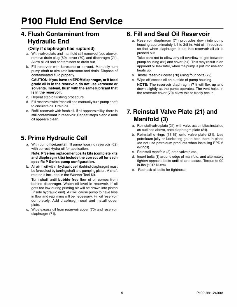
4. Flush Contaminant from Hydraulic End (Only if diaphragm has ruptured)a. Withvalveplateandmanifoldstillremoved(seeabove),
removedrainplug(69),cover(70),anddiaphragm(71).Allowalloilandcontaminanttodrainout.
b. Fill reservoir with kerosene or solvent. Manually turnpumpshafttocirculatekeroseneanddrain.Disposeofcontaminatedfluidproperly.
CAUTION: If you have an EPDM diaphragm, or if food grade oil is in the reservoir, do not use kerosene or solvents. Instead, flush with the same lubricant that is in the reservoir.
c. Repeatstepbflushingprocedure. d.Fillreservoirwithfreshoilandmanuallyturnpumpshaft
tocirculateoil.Drainoil. e.Refillreservoirwithfreshoil.Ifoilappearsmilky,thereis
stillcontaminantinreservoir.Repeatstepscandduntiloilappearsclean.
5. Prime Hydraulic Cell a.Withpumphorizontal,fillpumphousingreservoir(6�)
withcorrectHydraoilforapplication. Note: P Series replacement parts kits (complete kits
and diaphragm kits) include the correct oil for each specific P Series pump configuration.
b.Allairinoilwithinhydrauliccell(behinddiaphragm)mustbeforcedoutbyturningshaftandpumpingpiston.AshaftrotatorisincludedintheWannerToolKit.
Turn shaft until bubble-free flow of oil comes frombehind diaphragm. Watch oil level in reservoir. If oilgetstoolowduringprimingairwillbedrawnintopiston(insidehydraulicend).Airwillcausepumptohavelossinflowandreprimingwillbenecessary.Filloilreservoircompletely. Add diaphragm seal and install coverplate.
c. Wipeexcessoilfromreservoircover(70)andreservoirdiaphragm(71).
P100 Fluid End Service6. Fill and Seal Oil Reservoir a.Reservoir diaphragm (71) protrudes down into pump
housingapproximately1/4to3/8in.Addoil,ifrequired,so thatwhendiaphragm is set into reservoir all air ispushedout.
Takecarenottoallowanyoiloverflowtogetbetweenpumphousing(6�)andcover(54).Thismayresultinanapparentoilleaklater,whenthepumpisputintouseandheatsup.
b. Installreservoircover(70)usingfourbolts(7�). c. Wipeoffexcessoilonoutsideofpumphousing. NOTE: The reservoir diaphragm (71) will flex up and
downslightlyasthepumpoperates.Theventholesinthereservoircover(70)allowthistofreelyoccur.
7. Reinstall Valve Plate (21) and Manifold (3) a.Reinstallvalveplate(�1),withvalveassembliesinstalled
asoutlinedabove,ontodiaphragmplate(�4). b.Reinstall o-rings (18,19) onto valve plate (�1). Use
petroleumjellyorlubricatinggeltoholdtheminplace(donotusepetroleumproductswheninstallingEPDMo-rings).
c. Reinstallmanifold(3)ontovalveplate. d. Insertbolts(1)aroundedgeofmanifold,andalternately
tightenoppositeboltsuntilallaresecure.Torqueto90in-lbs(1017N-cm).
e. Recheckallboltsfortightness.
10 P100-991-�400A
W0039
R
O
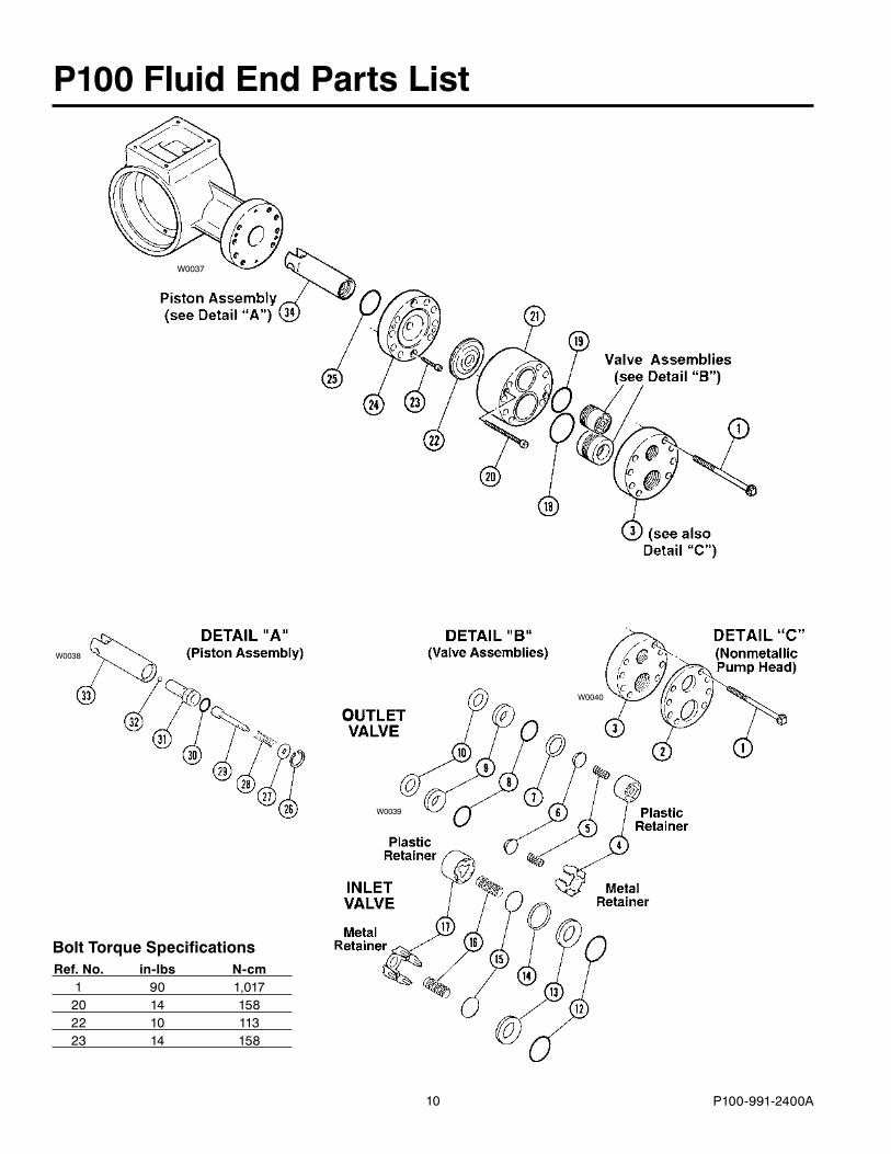
P100 Fluid End Parts List
Bolt Torque Specifications Ref. No. in-lbs N-cm 1 90 1,017 �0 14 158 �� 10 113 �3 14 158
W0037
W0040
W0038
11 P100-991-�400A
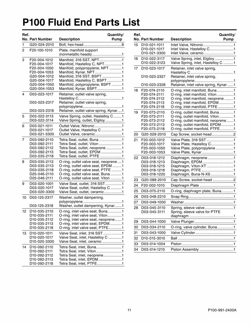
P100 Fluid End Parts List
1 G�0-0�4-�010 Bolt,hex-head.....................................8� F�0-100-1010 Plate,manifoldsupport (nonmetallicheads).............................13 F�0-004-101� Manifold,316SST,NPT......................1 F�0-004-1017 Manifold,HastelloyC,NPT.................1 F�0-004-1050 Manifold,polypropylene,NPT............1 F�0-004-1053 Manifold,Kynar,NPT..........................1 G�0-004-101� Manifold,316SST,BSPT...................1 G�0-004-1017 Manifold,HastelloyC,BSPT..............1 G�0-004-1050 Manifold,polypropylene,BSPT..........1 G�0-004-1053 Manifold,Kynar,BSPT........................14 D03-0�3-1017 Retainer,outletvalvespring, HastelloyC..........................................1 D03-0�3-�317 Retainer,outletvalvespring, polypropylene......................................1 D03-0�3-�318 Retainer,outletvalvespring,Kynar....15 D03-0��-3113 ValveSpring,outlet,HastelloyC........1 D03-0��-3114 ValveSpring,outlet,Elgiloy................16 D03-0�1-1011 OutletValve,Nitronic..........................1 D03-0�1-1017 OutletValve,HastelloyC....................1 D03-0�1-3300 OutletValve,ceramic..........................17 D03-09�-�110 TetraSeal,outlet,Buna......................1 D03-09�-�111 TetraSeal,outlet,Viton......................1 D03-09�-�11� TetraSeal,outlet,neoprene...............1 D03-09�-�113 TetraSeal,outlet,EPDM....................1 D03-035-�118 TetraSeal,outlet,PTFE.....................18 D03-035-�11� O-ring,outletvalveseat,neoprene....1 D03-035-�113 O-ring,outletvalveseat,EPDM.........1 D03-035-�118 O-ring,outletvalveseat,PTFE..........1 D�5-046-�110 O-ring,outletvalveseat,Buna...........1 D�5-046-�111 O-ring,outletvalveseat,Viton...........19 D03-0�0-1001 ValveSeat,outlet,316SST................1 D03-0�0-1017 ValveSeat,outlet,HastelloyC...........1 D03-0�0-3300 ValveSeat,outlet,ceramic.................110 D03-1�5-�317 Washer,outletdampening, polypropylene......................................1 D03-1�5-�318 Washer,outletdampening,Kynar.......11� D10-035-�110 O-ring,inletvalveseat,Buna..............1 D10-035-�111 O-ring,inletvalveseat,Viton..............1 D10-035-�11� O-ring,inletvalveseat,neoprene.......1 D10-035-�113 O-ring,inletvalveseat,EPDM............1 D10-035-�118 O-ring,inletvalveseat,PTFE.............113 D10-0�0-1011 ValveSeat,inlet,316SST..................1 D10-0�0-1017 ValveSeat,inlet,HastelloyC.............1 D10-0�0-3300 ValveSeat,inlet,ceramic...................114 D10-09�-�110 TetraSeal,inlet,Buna.........................1 D10-09�-�111 TetraSeal,inlet,Viton.........................1 D10-09�-�11� TetraSeal,inlet,neoprene..................1 D10-09�-�113 TetraSeal,inlet,EPDM.......................1 D10-09�-�118 TetraSeal,inlet,PTFE........................1
15 D10-0�1-1011 InletValve,Nitronic.............................1 D10-0�1-1017 InletValve,HastelloyC.......................1 D10-0�1-3300 InletValve,ceramic.............................116 D10-0��-3117 ValveSpring,inlet,Elgiloy..................1 D10-0��-31�3 ValveSpring,inlet,HastelloyC..........117 D10-0�3-1017 Retainer,inletvalvespring, HastelloyC..........................................1 D10-0�3-�3�7 Retainer,inletvalvespring, polypropylene......................................1 D10-0�3-�3�8 Retainer,inletvalvespring,Kynar......118 F�0-074-�110 O-ring,inletmanifold,Buna................1 F�0-074-�111 O-ring,inletmanifold,Viton................1 F�0-074-�11� O-ring,inletmanifold,neoprene.........1 F�0-074-�113 O-ring,inletmanifold,EPDM..............1 F�0-074-�118 O-ring,inletmanifold,PTFE...............119 F�0-073-�110 O-ring,outletmanifold,Buna..............1 F�0-073-�111 O-ring,outletmanifold,Viton..............1 F�0-073-�11� O-ring,outletmanifold,neoprene.......1 F�0-073-�113 O-ring,outletmanifold,EPDM............1 F�0-073-�118 O-ring,outletmanifold,PTFE.............1�0 G�0-0�9-�010 CapScrew,socket-head.....................��1 F�0-003-101� ValvePlate,316SST..........................1 F�0-003-1017 ValvePlate,HastelloyC......................1 F�0-003-1050 ValvePlate,polypropylene.................1 F�0-003-1053 ValvePlate,Kynar...............................1�� D03-018-1�1� Diaphragm,neoprene.........................1 D03-018-1�13 Diaphragm,EPDM..............................1 D03-018-1�15 Diaphragm,Viton-XT..........................1 D03-018-1�18 Diaphragm,PTFE...............................1 D03-018-1��0 Diaphragm,Buna-N-XS......................1�3 G�0-088-�010 Cap-Screw,socket-head....................��4 F�0-00�-1010 DiaphragmPlate.................................1�5 D03-075-�110 O-ring,diaphragmplate,Buna............1�6 D03-048-��10 SnapRing............................................1�7 D03-049-1000 Washer................................................1�8 D03-045-3110 Spring,sleevevalve............................1 D03-045-3111 Spring,sleevevalveforPTFE diaphragm...........................................1�9 D03-044-1000 ValvePlunger......................................130 D03-034-�110 O-ring,valvecylinder,Buna................131 D03-043-1000 ValveCylinder.....................................13� D10-015-3010 Ball......................................................133 D03-014-1004 Piston..................................................134 D03-014-1�10 PistonAssembly.................................1
Ref. Quantity/ No. Part Number Description Pump
Ref. Quantity/ No. Part Number Description Pump
1� P100-991-�400A
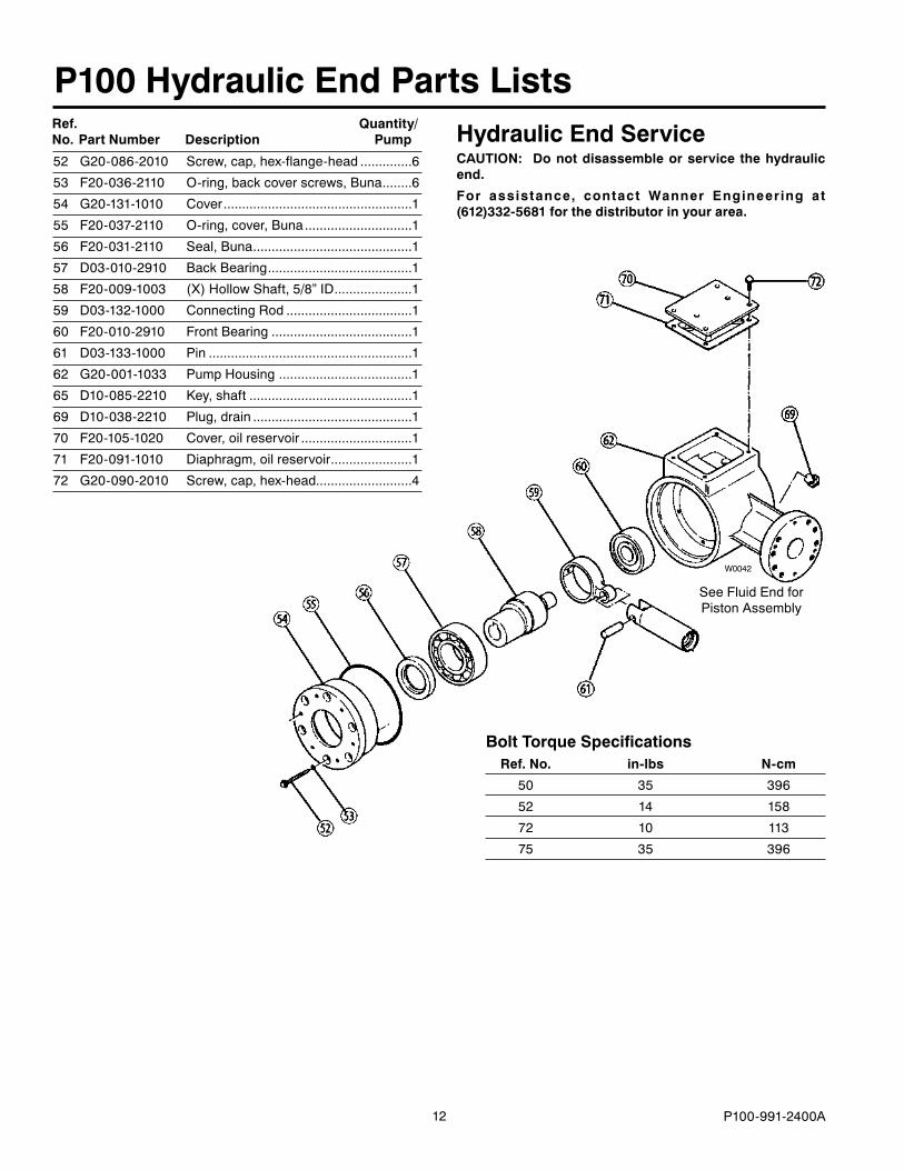
W0042
5� G�0-086-�010 Screw,cap,hex-flange-head..............6
53 F�0-036-�110 O-ring,backcoverscrews,Buna........6
54 G�0-131-1010 Cover...................................................1
55 F�0-037-�110 O-ring,cover,Buna.............................1
56 F�0-031-�110 Seal,Buna...........................................1
57 D03-010-�910 BackBearing.......................................1
58 F�0-009-1003 (X)HollowShaft,5/8”ID.....................1
59 D03-13�-1000 ConnectingRod..................................1
60 F�0-010-�910 FrontBearing......................................1
61 D03-133-1000 Pin.......................................................1
6� G�0-001-1033 PumpHousing....................................1
65 D10-085-��10 Key,shaft............................................1
69 D10-038-��10 Plug,drain...........................................1
70 F�0-105-10�0 Cover,oilreservoir..............................1
71 F�0-091-1010 Diaphragm,oilreservoir......................1
7� G�0-090-�010 Screw,cap,hex-head..........................4
P100 Hydraulic End Parts Lists
Bolt Torque Specifications Ref. No. in-lbs N-cm
50 35 396
5� 14 158
7� 10 113
75 35 396
SeeFluidEndforPistonAssembly
Hydraulic End ServiceCAUTION: Do not disassemble or service the hydraulic end.
For assistance, contact Wanner Engineering at (612)332-5681 for the distributor in your area.
Ref. Quantity/ No. Part Number Description Pump
13 P100-991-�400A
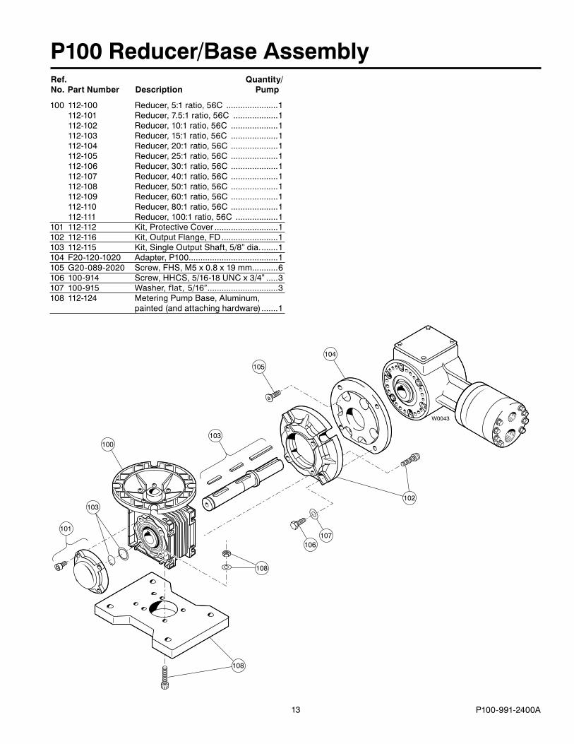
P100 Reducer/Base Assembly
100 11�-100 Reducer,5:1ratio,56C......................1 11�-101 Reducer,7.5:1ratio,56C...................1 11�-10� Reducer,10:1ratio,56C....................1 11�-103 Reducer,15:1ratio,56C....................1 11�-104 Reducer,�0:1ratio,56C....................1 11�-105 Reducer,�5:1ratio,56C....................1 11�-106 Reducer,30:1ratio,56C....................1 11�-107 Reducer,40:1ratio,56C....................1 11�-108 Reducer,50:1ratio,56C....................1 11�-109 Reducer,60:1ratio,56C....................1 11�-110 Reducer,80:1ratio,56C....................1 11�-111 Reducer,100:1ratio,56C..................1101 11�-11� Kit,ProtectiveCover...........................110� 11�-116 Kit,OutputFlange,FD........................1103 11�-115 Kit,SingleOutputShaft,5/8”dia........1104 F�0-1�0-10�0 Adapter,P100......................................1105 G�0-089-�0�0 Screw,FHS,M5x0.8x19mm...........6106 100-914 Screw,HHCS,5/16-18UNCx3/4”.....3107 100-915 Washer,flat, 5/16”..............................3108 11�-1�4 MeteringPumpBase,Aluminum, painted(andattachinghardware).......1
103
108
108
101
100
105
103
104
W0043
106
102
107
Ref. Quantity/ No. Part Number Description Pump
14 P100-991-�400A
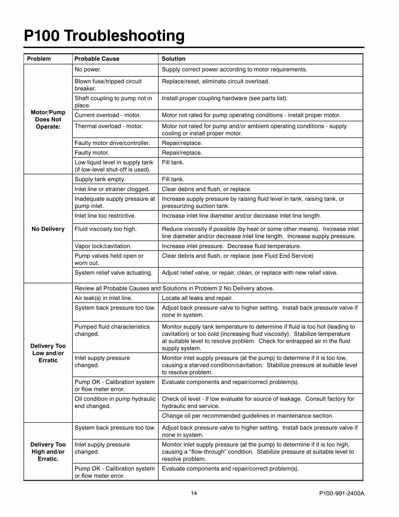
P100 TroubleshootingProblem Probable Cause Solution
Motor/Pump Does Not Operate:
Nopower. Supplycorrectpoweraccordingtomotorrequirements.
Blownfuse/trippedcircuitbreaker.
Replace/reset,eliminatecircuitoverload.
Shaftcouplingtopumpnotinplace.
Installpropercouplinghardware(seepartslist).
Currentoverload-motor. Motornotratedforpumpoperatingconditions-installpropermotor.
Thermaloverload-motor. Motornotratedforpumpand/orambientoperatingconditions-supplycoolingorinstallpropermotor.
Faultymotordrive/controller. Repair/replace.
Faultymotor. Repair/replace.
Lowliquidlevelinsupplytank(iflow-levelshut-offisused).
Filltank.
No Delivery
Supplytankempty. Filltank.
Inletlineorstrainerclogged. Cleardebrisandflush,orreplace.
Inadequatesupplypressureatpumpinlet.
Increasesupplypressurebyraisingfluidlevelintank,raisingtank,orpressurizingsuctiontank.
Inletlinetoorestrictive. Increaseinletlinediameterand/ordecreaseinletlinelength.
Fluidviscositytoohigh. Reduceviscosityifpossible(byheatorsomeothermeans).Increaseinletlinediameterand/ordecreaseinletlinelength.Increasesupplypressure.
Vaporlock/cavitation. Increaseinletpressure.Decreasefluidtemperature.
Pumpvalvesheldopenorwornout.
Cleardebrisandflush,orreplace(seeFluidEndService)
Systemreliefvalveactuating. Adjustreliefvalve,orrepair,clean,orreplacewithnewreliefvalve.
Delivery Too Low and/or
Erratic
ReviewallProbableCausesandSolutionsinProblem�NoDeliveryabove.
Airleak(s)ininletline. Locateallleaksandrepair.
Systembackpressuretoolow. Adjustbackpressurevalvetohighersetting.Installbackpressurevalveifnoneinsystem.
Pumpedfluidcharacteristicschanged.
Monitorsupplytanktemperaturetodetermineiffluidistoohot(leadingtocavitation)ortoocold(increasingfluidviscosity).Stabilizetemperatureatsuitableleveltoresolveproblem.Checkforentrappedairinthefluidsupplysystem.
Inletsupplypressurechanged.
Monitorinletsupplypressure(atthepump)todetermineifitistoolow,causingastarvedcondition/cavitation.Stabilizepressureatsuitableleveltoresolveproblem.
PumpOK-Calibrationsystemorflowmetererror.
Evaluatecomponentsandrepair/correctproblem(s).
Oilconditioninpumphydraulicendchanged.
Checkoillevel-iflowevaluateforsourceofleakage.Consultfactoryforhydraulicendservice.
Changeoilperrecommendedguidelinesinmaintenancesection.
Delivery Too High and/or
Erratic.
Systembackpressuretoolow. Adjustbackpressurevalvetohighersetting.Installbackpressurevalveifnoneinsystem.
Inletsupplypressurechanged.
Monitorinletsupplypressure(atthepump)todetermineifitistoohigh,causinga“flow-through”condition.Stabilizepressureatsuitableleveltoresolveproblem.
PumpOK-Calibrationsystemorflowmetererror.
Evaluatecomponentsandrepair/correctproblem(s).
15 P100-991-�400A
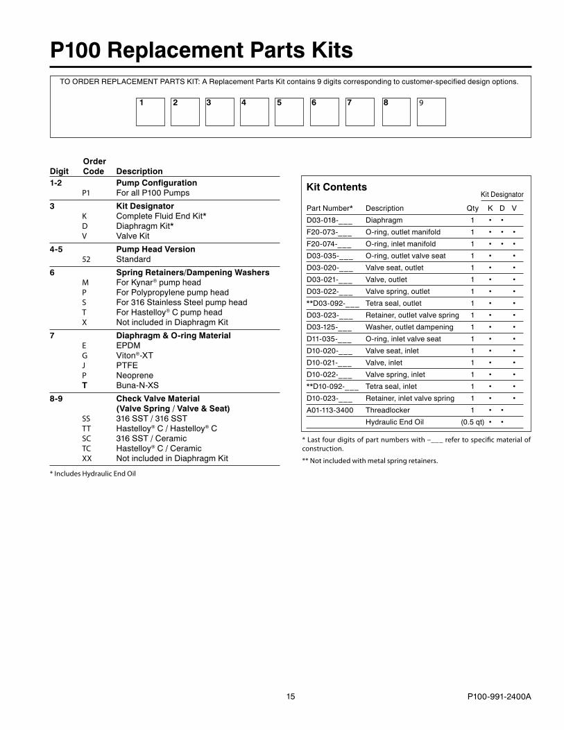
P100 Replacement Parts Kits
1-2 Pump Configuration P1 ForallP100Pumps
3 Kit Designator K CompleteFluidEndKit* D DiaphragmKit* V ValveKit
4-5 Pump Head Version 52 Standard
6 Spring Retainers/Dampening Washers M ForKynar®pumphead P ForPolypropylenepumphead S For316StainlessSteelpumphead T ForHastelloy®Cpumphead X NotincludedinDiaphragmKit
7 Diaphragm & O-ring Material E EPDM G Viton®-XT J PTFE P Neoprene T Buna-N-XS
8-9 Check Valve Material (Valve Spring / Valve & Seat) SS 316SST/316SST TT Hastelloy®C/Hastelloy®C SC 316SST/Ceramic TC Hastelloy®C/Ceramic XX NotincludedinDiaphragmKit
6 95321 84
KitDesignator
PartNumber* Description Qty K D V
D03-018-___ Diaphragm 1 • •
F�0-073-___ O-ring,outletmanifold 1 • • •
F�0-074-___ O-ring,inletmanifold 1 • • •
D03-035-___ O-ring,outletvalveseat 1 • •
D03-0�0-___ Valveseat,outlet 1 • •
D03-0�1-___ Valve,outlet 1 • •
D03-0��-___ Valvespring,outlet 1 • •
**D03-09�-___ Tetraseal,outlet 1 • •
D03-0�3-___ Retainer,outletvalvespring 1 • •
D03-1�5-___ Washer,outletdampening 1 • •
D11-035-___ O-ring,inletvalveseat 1 • •
D10-0�0-___ Valveseat,inlet 1 • •
D10-0�1-___ Valve,inlet 1 • •
D10-0��-___ Valvespring,inlet 1 • •
**D10-09�-___ Tetraseal,inlet 1 • •
D10-0�3-___ Retainer,inletvalvespring 1 • •
A01-113-3400 Threadlocker 1 • •
HydraulicEndOil (0.5qt) • •
Kit Contents
* Last four digits of part numbers with –___ refer to specific material of construction.
** Not included with metal spring retainers.
7
Order Digit Code Description
TOORDERREPLACEMENTPARTSKIT:AReplacementPartsKitcontains9digitscorrespondingtocustomer-specifieddesignoptions.
* Includes Hydraulic End Oil
16
WANNER ENGINEERING, INC.
1204 Chestnut Avenue, Minneapolis, MN 55403 TEL: (612) 332-5681 FAX: (612) 332-6937 TOLL-FREE FAX [US only]: (800) 332-6812
www.epmpump.com email: [email protected]
Limited WarrantyWannerEngineering,Inc.extendstotheoriginalpurchaserofequipmentmanufacturedbyitandbearingitsname,alimitedone-yearwarrantyfromthedateofpurchaseagainstdefects in material or workmanship, provided that theequipmentisinstalledandoperatedinaccordancewiththerecommendationsandinstructionsofWannerEngineering,Inc.WannerEngineering,Inc.willrepairorreplace,atitsoption, defective parts without charge if such parts arereturnedwith transportationchargesprepaid toWannerEngineering, Inc., 1�04 Chestnut Avenue, Minneapolis,Minnesota55403.
Thiswarrantydoesnotcover:
1. The electric motors (if any), which are covered bythe separate warranties of the manufacturers of thesecomponents.
�.Normalwearand/ordamagecausedbyor related toabrasion, corrosion, abuse, negligence, accident, faultyinstallationortamperinginamannerwhichimpairsnormaloperation.
3.Transportationcosts.
This limited warranty is exclusive, and is in lieu of anyotherwarranties(expressor implied) includingwarrantyofmerchantabilityorwarrantyof fitness foraparticularpurpose and of any non-contractual liabilities includingproduct liabilities based on negligence or strict liability.Every form of liability for direct, special, incidental orconsequential damages or loss is expressly excludedanddenied.
P100-991-�400A8/�005,Revised1/�006©�005WannerEngineering,Inc.PrintedinUSA

![INDEX []202014-%BDy%C6%B7%D0... · sc007 hino sh35t r long 3/8” npt sc008 hino r port thread 3/8”npt short sc009 mitsubishi fuso port thread 1/4" npt sc010 trailer t30 ... 642-09004](https://img.pdfslide.us/doc/110x75/5c0408d009d3f21e408d237a/index-202014-bdyc6b7d0-sc007-hino-sh35t-r-long-38-npt-sc008-hino.jpg)