Embed Size (px)
Citation preview

LIGHTING PANELs
Selection and Application Guide
Siemens Energy & Automation, Inc.3333 Old Milton ParkwayAlpharetta, GA 30005
www.sea.siemens.com/i-3
©2007 Siemens Energy & Automation, Inc. All Right Reserved.Siemens is a registered trademark of Siemens AG. Product Names mentioned may be trademarks or registered trademarks of their respective companies. Specifi cations are subject to change without notice.
PBSA-i3TECH-0707 New 5M0707CW Printed in USA
p1 series
i-3 Control Technology™

P1 Series Lighting Panel with i-3 Control Technology
OverviewSiemens P1 Series Lighting Panel withi-3 Control Technology is the next step in engineering innovation for our lighting control product portfolio. i-3 is a lighting control solution that allows engineers and end users to integrate, install, and interface controllable breakers into their electrical applications; hence the name i-3.
i-3 is designed to provide a simple,fl exible, compact solution for controlling branch lighting circuits remotely via a time schedule or an external signal (i.e. a switch, Building Automation System, etc.). i-3 reduces energy consumption by providing programmable remote control of Siemens BQD frame breakers with the use of our patented CPODs. This modular design produces a “smart” breaker type system that whencompared to traditional systems
1
lowers installation costs, minimizes the impact and cost of future system modifi cations, makes retrofi t applications less tedious, and reduces component replacement costs. i-3 offers a touch screen panel on its system controller that provides a user friendly graphical interface for commissioning and scheduling. All i-3 components mount inside a standard P1 lighting panel to provide valuable space savings. i-3 can stand-alone or be networked into a larger Building Automation System (BAS).
Panel Amp Ratings: Up to 250A
System Ratings:3 phase, 4-wire, 480Y/277V AC3 phase, 4-wire, 208Y/120V AC1 phase, 3-wire, 120/240V AC
Panel Size: 18, 30, 42 circuits
Mains: Breaker or Lug
Enclosures: NEMA 1, 3R, 3R/12, 4X, 4
Dimensions:20” wide x 5.75” deep (End walls with knockouts supplied at no charge, if requested at the time of order)
Mounting: Flush or Surface
Front: Hinged, piano hinged, door-in-door, screw to the box
Approvals:
UL 916 Energy Management EquipmentUL 67 PanelsUL 50 EnclosuresUL 489 BreakersCA Title 24
Operating Conditions:
Ambient temperature operating: 23�F...104�F (-5�C...40�C)Ambient temperature non-operating: -13�F...158�F (-25�C...70�C)
integration � Small footprint — can stack up to two 42 circuit panels in one section of an IPS Switchboard � Works with new and existing Siemens P1 Panel Installations � Up to 8 panels can be controlled from one system controller
interface � EIB, MODBUS, and dry contact capable* � USB interface for uploading and downloading panel confi gurations (Only with System Controller) � Integrated touch panel w/intuitive commissioning setup wizards (no PC required). PC interface also available.*Check with factory for future Bacnet capability.
installation � Modular design with use of standard breakers used, add CPODs only where control is needed � Reduced wiring complexity over traditional systems � Reduced labor and installation costs
Specifi cations:

System ControllerSystem ControllerSystem Controller
System Controller
i-3 System Overview
MLO/MainBreaker Space
Ground Bar
i-3 Controller
Data Rail(Cover removed for picture)
CPOD
BQD Breaker
NeutralExtension
ConvenientFront PanelCommunicationPorts (throughdeadfront)
System ControllerI/O Controller
� 250A max. bus� No column mounted panels� No feed thru or sub feed lugs� No split bus� No internal TVSS2
(deadfront/door removed for picture)

Load Lug Terminal
BQD Line Connection
3
Branch Circuit Breakers
Only thermal magnetic circuit breakers can be used with i-3. BQD breakers are required for all control points. BL breakers can be used for 240V applications involving non-controlled points.
Interrupting Rate (RMS kA)
PolesVolts (AC)
120 240 277 480
1 65 - 14 -
2 - 65 - 14
Poles Amperage(@ 408 C)
CatalogNumber
115A BQD115
20A BQD120
2 15A BQD215
20A BQD220
Breaker Selection
BQD 15A Breaker Side View

CPOD
The CPOD is a remotely operated electro-mechanical relay that is attached to a Siemens BQD molded case circuit breaker that allow loadsto be switched ON and OFF. The CPOD has the following features:
� UL Listed 489 CB Accessory� Same kA rating as the BQD breaker� Rated for 500,000 + operations
The CPOD connects to the load side of the breaker using the conductor tab that is inserted into the breaker load lug. The CPOD load lug is the same size as the circuit breaker load lug. Therefore, the load wire connections are attached to the load lug of the CPOD.
Manual Override The CPOD has a manual override that forces the main contacts in the CPOD from the open position to the closed position. Once the override lever is rotated to the closed position, the contacts remain closed until the CPOD receives a remote signal from the controller. This feature allowselectrical loads to be tested prior to confi guring the lighting control system which can be useful during installation and commissioning. The manual override of remote commands is momentary until controller is commissioned and takes over operation and is purely mechanical. There is no electrical feedback associated with the override.
Maglatch mechanismThe CPODs switch ON/OFF via a maglatch mechanism. The maglatch mechanism is designed to hold and actuate between the On and Off state. This bi-stable operation is achieved with the use of a solenoid, a permanent magnet, and a spring that ensure the CPOD contacts remain in its last state if power is lost. When power is restored, normal operation resumes. Unlike motor driven mechanisms that are prone to high inrush currents, slippage, failure, and loud noise due to the operation of the DC motor, the
maglatch mechanism is low power requiring approximately 1.7A @ 24VDC for 2-25 milliseconds, provides rapid operation that breaks continuity in less than 4.5 milliseconds, provides longer mechanical life of more than
half a million operations, and is quiet where the only noise is the sound of the contacts striking. CPOD statistics can be retrieved via the System Controller or the Modbus map that indicate to the user the number of times the CPOD has opened or closed and allows the user to determine when the CPOD has reached 500,000 operations.
Components Description
1 Conductor tab The conductive element that connects the circuit breaker to the CPOD
2 Mechanical Status Indicator Provides the open/close status of the CPOD contacts
3* Manual Override Allows the user to close the CPOD contacts if system is offl ine.
4 CPOD Load Lug The terminal that connects CPOD to the lighting loads
5 CPOD Connector 4-pin connector that links CPOD to the data rail
4
Components
1 Manual Override
2 Maglatch Mechanism
3 Blow-Closed Mechanism
4 Integrated Electronics
�
��
�
�
�
�
�
�
* If the manual override is engaged while the controller is functioning, the controller will re-open the contacts. Signals from the controller take priority when functioning. This minimizes tampering when the system is functioning.
CPOD
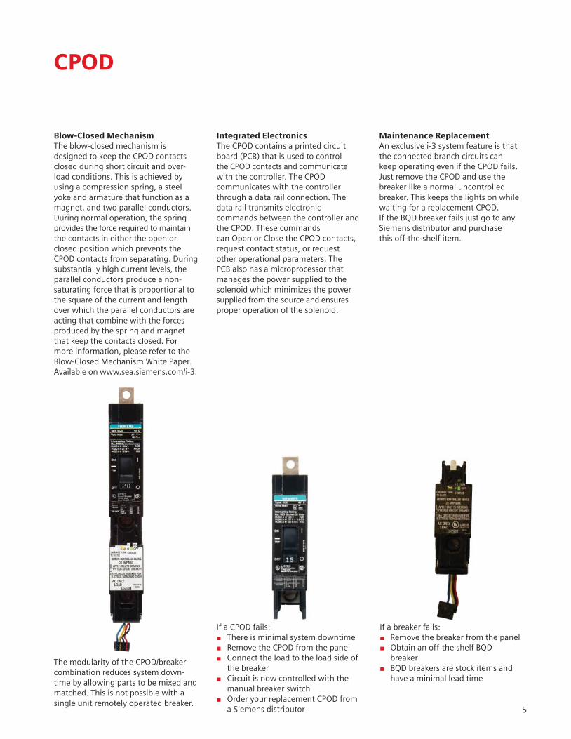
Blow-Closed MechanismThe blow-closed mechanism is designed to keep the CPOD contacts closed during short circuit and over-load conditions. This is achieved by using a compression spring, a steel yoke and armature that function as a magnet, and two parallel conductors. During normal operation, the spring provides the force required to maintain the contacts in either the open or closed position which prevents the CPOD contacts from separating. During substantially high current levels, the parallel conductors produce a non-saturating force that is proportional to the square of the current and length over which the parallel conductors are acting that combine with the forces produced by the spring and magnet that keep the contacts closed. For more information, please refer to the Blow-Closed Mechanism White Paper. Available on www.sea.siemens.com/i-3.
Integrated ElectronicsThe CPOD contains a printed circuit board (PCB) that is used to control the CPOD contacts and communicate with the controller. The CPOD communicates with the controller through a data rail connection. The data rail transmits electronic commands between the controller and the CPOD. These commands can Open or Close the CPOD contacts, request contact status, or request other operational parameters. The PCB also has a microprocessor that manages the power supplied to the solenoid which minimizes the power supplied from the source and ensures proper operation of the solenoid.
Maintenance ReplacementAn exclusive i-3 system feature is that the connected branch circuits can keep operating even if the CPOD fails. Just remove the CPOD and use the breaker like a normal uncontrolled breaker. This keeps the lights on while waiting for a replacement CPOD.If the BQD breaker fails just go to any Siemens distributor and purchasethis off-the-shelf item.
The modularity of the CPOD/breaker combination reduces system down-time by allowing parts to be mixed and matched. This is not possible with a single unit remotely operated breaker.
If a CPOD fails:� There is minimal system downtime� Remove the CPOD from the panel� Connect the load to the load side of the breaker� Circuit is now controlled with the manual breaker switch � Order your replacement CPOD from a Siemens distributor
If a breaker fails:� Remove the breaker from the panel� Obtain an off-the shelf BQD breaker � BQD breakers are stock items and have a minimal lead time
5

Controllers
The i-3 P1 Series Lighting Control Panel has two available controllers that allow the user to implement time schedules, create zones, manage inputs, and display CPOD and system status through a serial connection or from the front mounted touchscreen panel. The I/O Board shown in Figure 1 provides the logic for the operation of the entire system.
Battery BackupIn the event that power is lost, a factory installed battery will maintain the system clock and panelboard confi gurations for at least one year.The lithium coin cell battery is rated for 10 years.
6
EIB SelectAddress
CommunicationInterface Section
Three-way “All Pods” Switch
Ribbon CableConnectors
Input WiringSection
Analog I/OTerminals
Power SupplyConnector
EIB ResetReset
BatteryBackup(up to1 year)
RS485terminal
Switch
Inpu
t Termin
als
Figure 1. I/O Board
The I/O Board input terminals are designed for 3-pin connections where the common terminal can be shared by two 2-wire inputs. These input terminals accept dry contact inputs from external control devices. Input connectors (shown in Figure 2) areprovided for the 16 input terminal sets.
Figure 2. Input Connector

I/O Controller
The I/O Controller provides the intelligence to switch the remoteoperated breakers On and Off. TheI/O Controller enables the P1 lighting panel to accept dry contact inputs and commands over communication networks.
Inputs and Outputs� Up to 32 Digital, 2-wire Inputs� Up to 16 Digital, 3-wire Inputs� Up to 2 Analog Inputs (Available August 2007)� Up to 2 Analog Outputs (Available August 2007)
Communication Interface� Modbus RTU� EIB
Features:� Confi gurable zones dependent on number of breakers per zone� Off Warning Blink (Available August 2007)
Communication CablesAn RS232/RS485 converter kit or USB/RS485 converter kit is requiredto allow communication between the i-3 I/O Controller and a personal computer. This kit can be owner furnished* or ordered through the factory using the following part numbers:� RS232/RS485 Kit: 5WG1 715-8XY01 � USB/RS485 Kit: 5WG1 715-8XY02
In addition to the converter, the kit includes:� DB9 Cable� Phoenix Connector
*Note: Contact Technical Support for Instructions
7

Initial Startup Screen
I/O Confi guration Software
I/O CONFIGURATION SOFTWAREThe i-3 Control Technology Panel Confi gurator makes commissioning and monitoring your lighting control system quick and easy. The i-3 Confi gurator Software is a Windows based application that provides intuitive screens that allow the user to easily confi gure a P1 Series Lighting Control Panel with i-3 Control Technology. This software is included with the system. Please contact Siemens Energy and Automation Technical Support at 1.800.427.2256 to obtain a copy after your system isdelivered/installed.
The i-3 Control Technology Panel Confi gurator allows the user to:� See an accurate graphical panel layout � Check the status of breakers, inputs, and zones� Confi gure zones and I/O mappings� Import/ Export system confi gurations System Requirements� Net Framework 2.0� Windows XP, 2003, or newer versions
Status Screen: The graphical panel representation on the left indicates which PODs are open (green) or closed (red). The table on the right provides the status of up to 32 digital inputs.
Operations Screen: Allows the user to override the current POD status, create zones, and set I/O mappings.8

System Controller
In addition to the features of the I/O Controller, the system controller provides an intuitive touch screen panel application with set-up wizards to confi gure the system instead of the Confi guration Software used for the I/O Controller. Off-line confi guration software is also available from the factory. Please contact Siemens Energy & Automation, Inc. Technical Support at 1.800.427.2256 to obtain a copy. The System Controller also includes the Modbus TCP/IP communication protocol.
Features:� Touch Screen Panel� 6 Setup Wizards (Panels, Breakers, Inputs, Zones, I/O Mapping, and Schedules)� Password Protection� User Access Levels� Event Logs� Flexible Automatic Daylight Savings and leap year compensation� USB interface (details on page 10)� 20 independent schedules (10 events per schedule)� Unlimited holiday overrides� Modbus TCP/IP
This 24V low voltagesection is accessiblethrough the paneldeadfront.
System Controller Screenshots
Setup Wizards SchedulesPassword Protection
Tools and Overrides Zones I/O Mapping 9

10
USB Interface
The USB interface allows the user to upload or download panel confi guration fi les and software updates. This feature will ease the installation, commissioning, and support of i-3 equipped panelboards because upgrades will no longer re-quire “experts” in lighting control. On occassions when technical assistance is needed, the confi guration fi les can be downloaded to a USB stick and uploaded to a computer where the user can send an email with the attached fi les to technical support. After the issue is remotely diagnosed, the fi le can be e-mailed back to the user and uploaded. This will reduce customer downtime and the costs associated with technical assistance.
System Controller Screenshots
USB import fi le feature

RS-485
I/O Controllers
Modbus RS-485/RS-232orRS485/USB
Communication and NetworkingConfi gurations
The i-3 I/O Controller is capable of communicating via EIB, Modbus RS485, or dry contacts (future Bacnet capabilities). The i-3 System Controller is capable of all the I/O Controller communication methods and optional Modbus TCP/IP. Modbus TCP/IP allows the system controller to communicate to other building systems over the building LAN. Each panel in the
11
system acts as a stand-alone unit or a “slave” to a greater building automation system. One system controller in a panel can network up to 7 additional panels (for a total of 8 panels). The I/O Controller can also be networked with Modbus RS485 or on a LAN. In order to network panels, 18 gauge twisted pair wires are used to communicate through EIB. The total
maximum cable length allowed for networking panels is 3,300 ft (1,000 meters).Note: Future versions of the system controller will be Internet capable for remote access and confi guration.Contact Siemens sales for more information.
...Up to 7 additional panels can be networked from a single system controller
EIB
SystemController
I/O Controllers
EIB
1st Floor...up to 7 I/O Controllers
2nd Floor...up to 7 I/O Controllers
SystemController 1
SystemController 2
ModbusLAN/RS485
Note: System controllers cannot communicate with each other even if they are on the same LAN.
*Depending on maximum distance and network bandwidth.Note: Up to a maximum of 32 devices may be connected in one loop.
...Up to 247 I/0 Controller Modbus Slaves*
...Central building automation system can control several local system controllers. (i.e. Highrise application)
Modbus RTU orModbus TCP/IP
I/O Controllers
SystemController
...System Controller can be connected on a LAN
EIB

Dimensions
12
Type 1 Box
Type 3R and 3R/12 Box
AmpRating
EndGutter
NeutralLocation
125 10.500 11.500
250 10.500 11.500
Main Lug End Gutter Dimensions
BranchBreakers
WiringSpace
BQD + CPOD Combo 3.25
BQD 5.5
BL 6.375
Branch Breaker Side Gutter Wiring Space (inches)
Main Breaker
SideGutter
NeutralLocation
BL, BLH, HBL, BQD 8.500 11.500
ED4, ED6, HED4 6.125 11.500
QJ2,QJH2, QJ2-H 6.500 11.500
FD6, FXD6, HFD6 5.250 11.500
Main Breaker Gutter Dimensions (inches)

Ordering Information
i-3 is derived from a standard Siemens P1 panel. Please refer to the P1 Panelboard Selection and Application Guide to select the interior, enclosure modifi cations, and front options which can be found at: http://www.sea.siemens.com/products/power distribution/product/panelboards/panelboards-technical-overview.htm
Keep the following in mind when ordering a P1 Series Panel with i-3 Control Technology: � 250A Maximum Bus� No column mounted panels� No feed thru or sub feed lugs� No remote control switch or time clock (can be mounted externally)� No Fast-Latch Trim� No Split Bus� No 200 % Neutral� No Internal TVSS**
Summary of Ordering Steps:1. Select Interior and Main Device 2. Select Branch Breakers and CPODs3. Select the Controller4. Select Enclosure Modifi cations and Front Options (from P1 S&A Guide)5. Contact local Siemens Sales Representative for pricing and order entry.
**Can be mounted externally with use of branch mounted circuit breaker.
1. Select Interior and MainSelect the interior by bus type, panel rating, and the number of branch circuits.
Main Lugs Only*
MaxPanelAmps
Max1-Pole
Circuits
BoxHeight
(inches)
Catalog Numbers
120/240V1-ph, 3-wire
208Y/120V3-ph, 4-wire
480Y/277V3-ph, 4-wire
125
18 32 P1A18ML125ATS P1C18ML125ATS P1E18ML125ATS
30 38 P1A30ML125ATS P1C30ML125ATS P1E30ML125ATS
42 44 P1A42ML125ATS P1C42ML125ATS P1E42ML125ATS
250
18 32 P1A18ML250ATS P1C18ML250ATS P1E18ML250ATS
30 38 P1A30ML250ATS P1C30ML250ATS P1E30ML250ATS
42 44 P1A42ML250ATS P1C42ML250ATS P1E42ML250ATS
* Catalog Numbers are for aluminum main bus. For optional copper main bus change “A” in position 11 to “C”. For example, a 125A panel with 120/240V 1-phase, 4-wire would have the following catalog number: P1A18ML125CTS. Specify bottom feed by changing the character in position 12 from “T” (top) to “B”. Specify fl ush mount by changing the character in position 13 from “S” (surface) to “F”.
Main Circuit Breaker*
MaxPanelAmps
Max1-Pole
Circuits
BoxHeight
(inches)
Catalog Numbers
120/240V1-ph, 3-wire
208Y/120V3-ph, 4-wire
480Y/277V3-ph, 4-wire
100
18 32 P1A18BL100ATS P1C18BL100ATS P1E18BL100ATS
30 38 P1A30BL100ATS P1C30BL100ATS P1E30BL100ATS
42 44 P1A42BL100ATS P1C42BL100ATS P1E42BL100ATS
125
18 32 P1A18E4125ATS P1C18E4125ATS P1E18E4125ATS
30 38 P1A30E4125ATS P1C30E4125ATS P1E30E4125ATS
42 44 P1A42E4125ATS P1C42E4125ATS P1E42E4125ATS
225
18 32 P1A18QJ225ATS P1C18QJ225ATS P1E18QJ225ATS
30 38 P1A30QJ225ATS P1C30QJ225ATS P1E30QJ225ATS
42 44 P1A42QJ225ATS P1C42QJ225ATS P1E42QJ225ATS
250
18 32 P1A18FX250ATS P1C18FX250ATS P1E18FX250ATS
30 38 P1A30FX250ATS P1C30FX250ATS P1E30FX250ATS
42 44 P1A42FX250ATS P1C42FX250ATS P1E42FX250ATS
2. Select Branch Breakers and CPODs. BQD breakers are required for all control points.
BranchBreakers
BreakerType
PolesAvailable
Amp Rating
Max Interrupting Rate (kA)
120/240V 240V 277V
Controllable BQD 1,2 15, 20 65 - 14
Non-Controllable
BL 1, 2, 3
15, 20, 25, 30,35,40, 45, 50, 60
10 - -
70 10 - -
80, 90, 100
10 - -
13

Ordering Information
CPODS*
Amp Rating Poles Catalog Number
20 1 BQD-20-CPOD-1
20 2 BQD-20-CPOD-2
* Use the Catalog Number provided in the table to specify circuit breakers.NOTE: Contact sales for availabiliy of the future 30A rating.
3. Select Controller
Description Catalog Number
I/O Controller 5WG1 718-8XY01
System Controller 5WG1 718-8XY11
RS485/R232 Converter* 5WG1 715-8XY01
RS485/USB Converter* 5WG1 715-8XY02
*Communication cable factory available or owner constructed.
4. Enclosure Modifi cations and Front OptionsThere are several enclosure modifi cations and front options that are available and applicable for the P1 Series Panel with i-3 Control Technology. Please review the P1 Selection and Application (S&A) for details. Ordering Example:3-phase, 4-wire 480Y/277V AC250 Amp Main circuit breaker 42 Branch CircuitsBottom FeedSurface MountedHinged Trim30 – 20 Amp one-pole Controllable Breaker CPOD Combo3 – 20 Amp two-pole Controllable Breaker CPOD Combo6 – 30 Amp one-pole Non-Controllable BreakersSystem Controller
Panel
Step 1 (from P1 Guide)
Step 2 Step 3Step 4
(from P1 Guide)
Interior and Main Device
Breakers and CPODS:
Qty: Controller:
Enclosure Modifi cations
and Front Options
1 P1E42FX250ABS BQD-20-CPOD-1BQD-20-CPOD-2BQD120BQD230BQD130
3033036
5WG1 718-8XY11 HingedTrim
5. Contact your local Siemens Sales Representative for order entry. For your nearest sales offi ce call us at 1.800.964.4114 or visit www.sea.siemens.com/sales/salesoffi ces.html.
14

Ordering Information
Panel
Step 1 (from P1 Guide)
Step 2 Step 3 Step 4
Interior and Main Device:
Breakers and CPODS:
Qty.: Controller:Enclosure Modifi cations
and Front Options
1
2
3
4
5
6
7
8
15
Panel Confi guration Form

16
Integrated Power System Switchboards
The Single Source For Making Your Installations:Simpler, Smaller, and Quicker
With the integration of the P1 Series Lighting Control Panel with i-3 Control Technology into your next Integrated Power System, you have the ability to stack up to 2 panels with 42 branch controlled circuits each in one section!
The modular design of the Siemens Integrated Power System (IPS)switchboard allows the user to integrate electrical distribution equipment, power monitoring and environmental controls that typically mount in multiple enclosures into one switchboard line-up. Users have the freedom to confi gure an arrangement that best fi ts theirindividual needs. IPS can help reduce the cost of your next project. How you might ask. IPS reduces the number of components you have to handle and install which decreases the amount of time on the job site. It also simplifi es fi eld setup and pro-gramming, as well as, provides additional space for revenue-generating sales or storage space with its small footprint. Integrated Power System switchboards are built to UL 891 and NEMA PB-2 standards. Standard height of Integrated Power System sections is 90 inches (Optional 70 inches available). Minimum depth of IPS is 13.75 inches. Optional depths of 20, 28, and 38 inches are available.
For more information on IPS and what it can do for you, please contact your nearest Siemens Sales Offi ce at 1.800.964.4114 or visit www.sea.siemens.com/sales/salesoffi ces.html

LIGHTING PANELs
Selection and Application Guide
Siemens Energy & Automation, Inc.3333 Old Milton ParkwayAlpharetta, GA 30005
www.sea.siemens.com/i-3
©2007 Siemens Energy & Automation, Inc. All Right Reserved.Siemens is a registered trademark of Siemens AG. Product Names mentioned may be trademarks or registered trademarks of their respective companies. Specifi cations are subject to change without notice.
PBSA-i3TECH-0707 New 5M0707CW Printed in USA
p1 series
i-3 Control Technology™