Embed Size (px)
DESCRIPTION
P091.042.IM23x-MA.APN-DOC.101.A
Citation preview

APPLICATION NOTE 042.IM23x-MA.101 IM23x-MA 12/23/05 Getting started using IM23x-MA
©Technosoft 2005 APN.101 - 1
Problem:
For new users of an intelligent motor, starting to implement a motion control application can be a quite complex task. You need to know how to hook-up the components of the motion system, to configure them (motor, sensors and drive), test their functionality, identify parameters and tune controllers. Finally, execute a simple movement to validate the basic system functionality and focus on your real motion application.
Solution:
♦ Drive : ♦ S/W environment :
Technosoft Intelligent Motor IM23x-MA
Technosoft EasyMotion Studio
Description:
This Application Note explains: • how to perform the basic hardware connections for IM23x-MA; • how to create under the ‘EasyMotion Studio’ a new project/application
for motion control; • how to configure the components of the motion system: motor,
sensors, drive; • how to test the functionality of the system components; • how to identify the motor parameters and tune the controllers; • how to run and use data analysis tools; • how to save your project/application;
Connections:
Power supply connection
+3.3VDC
DCGNDGND
+LOG
12...48VDC
12...48VDC
+
+
+MOT VMOT
ABC
VLOG +5VDC
DCGND
J1
IM23x - MA v1.1
Mot
ionC
hipTM
Figure 1. J3 – Power supply connection

APPLICATION NOTE 042.IM23x-MA.101 IM23x-MA 12/23/05 Getting started using IM23x-MA
©Technosoft 2005 APN.101 - 2
2
3GND
Tx232Rx232
RS-232
Transceiver
+3.3V
J2
RS-232 Serial connection
RS-232
Mot
ionC
hipTM
2 1345
6789
IM23x - MA v1.1
Figure 2. J1 – Serial RS-232 connection
Follow the next steps for a hardware connection of the system components:
1. Connect the power supply, as you can see in Figure 1. 2. Connect the IM23x-MA to the PC computer as you can see in the Figure 2 3. First power up the PC 4. Secondly power up the drive
APPLICATION NOTE 042.IM23x-MA.101 IM23x-MA 12/23/05 Getting started using IM23x-MA
©Technosoft 2005 APN.101 - 3
Project set-up:
1. Create a new project
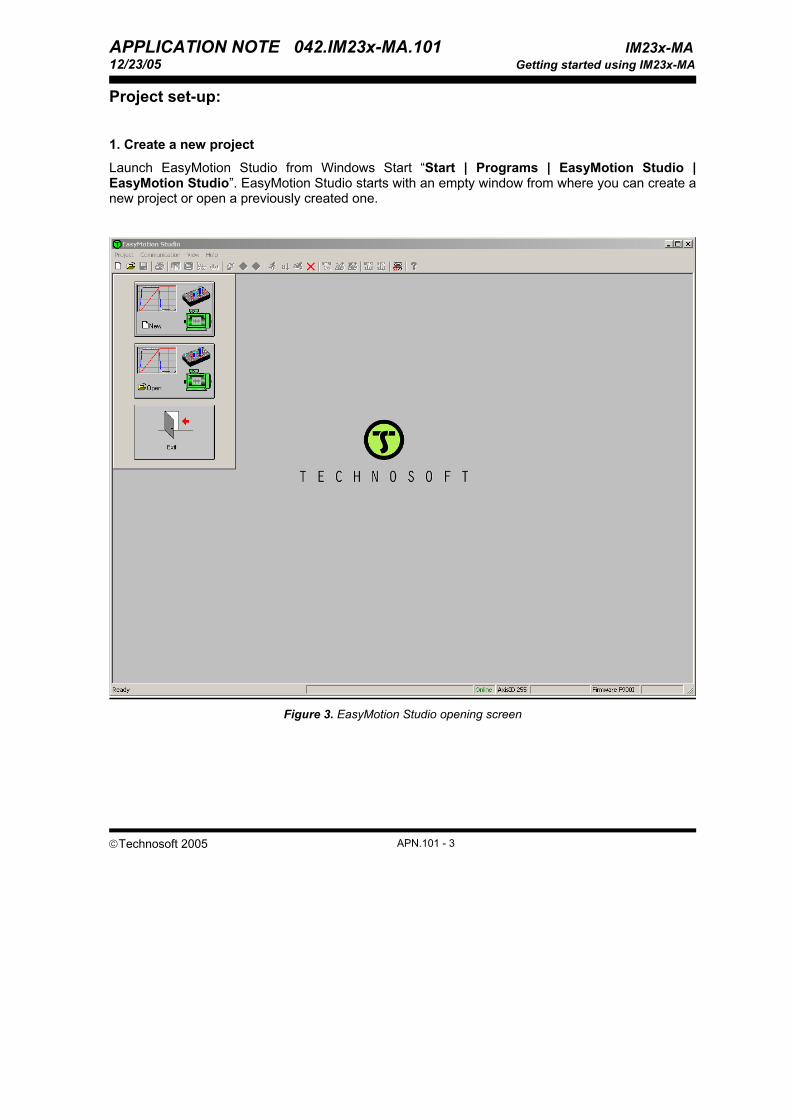
Launch EasyMotion Studio from Windows Start “Start | Programs | EasyMotion Studio | EasyMotion Studio”. EasyMotion Studio starts with an empty window from where you can create a new project or open a previously created one.
Figure 3. EasyMotion Studio opening screen

APPLICATION NOTE 042.IM23x-MA.101 IM23x-MA 12/23/05 Getting started using IM23x-MA
©Technosoft 2005 APN.101 - 4
Press New button to open the “New Project” dialogue. Set the axis number for your first application equal with your drive axis ID. The initial value proposed is 255 which is the default axis ID of the drives. Press New button and select your intelligent motor family: IM231, IM232 or IM233 and type: IM23x-MA.
Figure 4. Create a new project in EasyMotion Studio
Validate your selection with a mouse click. EasyMotion Studio opens the Project window where on the left side you can see the structure of the project. At beginning both the new project and its first application are named “Untitled”. The application has 2 components: S Setup and M Motion (program).

APPLICATION NOTE 042.IM23x-MA.101 IM23x-MA 12/23/05 Getting started using IM23x-MA
©Technosoft 2005 APN.101 - 5
Figure 5. Project window
2. Establish communication
If you have the drive connected with your PC, now its time to check the communication. Use menu command Communication | Setup to check/change your PC communication settings. Press the Help button of the dialogue opened. Here you can find detailed information about how to setup your drive/motor and the connections. Power on the drive/motor and then close the Communication | Setup dialogue with OK. If the communication is established, EasyMotion Studio displays in the status bar (the bottom line) the text “Online” plus the axis ID of your drive and its firmware version. Otherwise the text displayed is “Offline” and a communication error message tells you the error type. In this case, return to the Communication | Setup dialogue, press the Help button and check troubleshoots.
Note: When first started, EasyMotion Studio tries to communicate with your drive/motor via RS-232 and COM1 (default communication settings). If your drive/motor is powered and connected to your PC port COM1 via an RS-232 cable, the communication can be automatically established.

APPLICATION NOTE 042.IM23x-MA.101 IM23x-MA 12/23/05 Getting started using IM23x-MA
©Technosoft 2005 APN.101 - 6
3. Motor and drive setup
In the project window left side, select “S Setup”, to access the setup data for your application.
Press View/Modify button . This opens 2 setup dialogues: for Motor Setup and for Drive setup through which you can configure and parameterize your Technosoft intelligent motor. The Motor Setup dialogue presents the intelligent motor data, its sensors and allows you to setup the parameters of the transmission between the intelligent motor and the load. In the Drive Setup dialogue you can configure and parameterize the drive part of intelligent motor for your application. In each dialogue you will find a Guideline Assistant, which will guide you through the whole process of introducing and/or checking your data. 3.A. Brushless Motor Setup
The Motor Setup dialogue presents the intelligent motor data and its sensors. Also, in the dialogue you can specify the parameters of the transmission between the intelligent motor and the load.
Figure 6. Motor Setup dialogue

APPLICATION NOTE 042.IM23x-MA.101 IM23x-MA 12/23/05 Getting started using IM23x-MA
©Technosoft 2005 APN.101 - 7
Transmission to load. In the “Transmission to load” group box set the type and ratio of the transmission between the motor and load
Step 1. At Transmission type select Rotary to rotary for load with rotary motion or Rotary to linear for load with linear motion.
Step 2. Set the transmission ratio as the ratio of motor displacement over the load displacement, both values are signed. The transmission ratio is used to translate the position/speed reference from load position/speed units into motor position/speed units. The transmission ratio sign indicates the direction of the load movement: positive – same as the motor’s, negative – reversed to the motor’s.
Press the Ok button to keep the changes done since last entry in the Motor dialogue and go to Drive Setup dialogue. Press the Cancel button to exit without keeping the changes done since last entry in the Motor dialogue and go to Drive Setup dialogue.

APPLICATION NOTE 042.IM23x-MA.101 IM23x-MA 12/23/05 Getting started using IM23x-MA
©Technosoft 2005 APN.101 - 8
3.B. Drive Setup
Through the Drive Setup dialogue you can configure and parameterize the drive part of the intelligent motor for your application.
Use the Guideline Assistant, and follow the steps described. This will guide you through the whole process of setting up the drive. Use the Next button to see the next guideline step and the Previous button to return to the previous step.
The drive setup is accompanied by a series of tests having as goal to determine a part of the drive parameters and to validate the overall system behavior. The key data you need to introduce are the drive Power supply and the drive Current limit i.e. the maximum current to be used by the drive (see below for details).
CAUTION! Check carefully the drive Power supply and Current limit as well as the motor Nominal current and Peak current from the Motor Setup dialogue. If these parameters are incorrectly introduced, the tests will not work properly and can damage your motor!
Figure 7. The Drive Setup dialogue

APPLICATION NOTE 042.IM23x-MA.101 IM23x-MA 12/23/05 Getting started using IM23x-MA
©Technosoft 2005 APN.101 - 9
Step 1 Select the Control Mode
Position – the intelligent motor performs position control
Speed – the intelligent motor performs speed control
Torque – the intelligent motor performs torque/current control
If your application requires switching between position and speed control, select Position, press the Advanced button and in the group Control scheme choose the option Close position, speed and control loop.
Note: The default option for position control is to Close only position and current loop. In this configuration, the position controller output is a current/torque command and the speed controller is not used.
Step 2 Select the Commutation Method
Sinusoidal – the motor is treated like a PMSM (Permanent magnet synchronous motor) and is vector controlled using a FOC (field oriented control) algorithm. In this mode, the motor works with 3-phase sinusoidal voltages and currents.
Trapezoidal – the motor is controlled as brushless DC using Hall sensors for commutation. In this mode, the motor currents are rectangular and the BEMF voltages are trapezoidal. The trapezoidal mode is possible only if your motor is equipped with digital Hall sensors.
Step 3 Select the motion reference type in the External reference group box:
Yes – your intelligent motor gets the reference from an external device No – the reference is set only by the internal reference generator.
Press the Setup button to select the reference type and its parameters. Your selection is also shown in the external reference group box.
Automatically activated after Power On – after downloading the setup data, the motor starts at power to operate with the selected external reference without any other command. The intelligent motor must be set in the AUTORUN mode.
Step 4 Set the Drive operation parameters
Power supply – the supply voltage for the power stage (also named motor supply). Use Detect button to measure its actual value as applied to the intelligent motor. The supply voltage is used in the current controller(s) tuning.

APPLICATION NOTE 042.IM23x-MA.101 IM23x-MA 12/23/05 Getting started using IM23x-MA
©Technosoft 2005 APN.101 - 10
Figure 8 VDC Detection Test
Current limit – the maximum current used by the intelligent motor. Try to use the default value suggested. For very high dynamic moves, you may further increase this value. As a general rule, the current limit must be set bigger than the motor nominal current, but no more than the motor peak current.
Step 5 Set the Current Controller parameters:
• Kp – proportional term of the PI current controller
• Ki – integral term of the PI current controller
Press the Tune & Test button to open the Current controller tuning dialogue where you can tune and test the behavior of the current controller. The test has two steps:
• Set-up the test parameters in “Test parameters” tab
• Run the test in “Test” tab
This is a “hot” test, which applies power to the motor. It sets a current reference and during runtime it captures and displays the motor current, current reference and voltage reference values. The test does not move the motor.

APPLICATION NOTE 042.IM23x-MA.101 IM23x-MA 12/23/05 Getting started using IM23x-MA
©Technosoft 2005 APN.101 - 11
Figure 9 Current controller Tuning Test dialogue
Test Parameters tab
The current reference is a step signal equal with the value set in “Test current” parameter from the “Test Parameters” group box. When entering the dialogue, the program suggests a “Test current” equal with half of the motor nominal current. You may increase this value, up to 90% of the motor nominal current.
The “I Protection” parameter sets the over current protection limit. The protection time is set to minimum, i.e. the protection is immediately triggered if the motor current reaches “I Protection” value. The maximum value of “I Protection” is limited to motor peak current. The “I Protection” parameter must be bigger than the “Test current”

APPLICATION NOTE 042.IM23x-MA.101 IM23x-MA 12/23/05 Getting started using IM23x-MA
©Technosoft 2005 APN.101 - 12
Figure 10 Current controller tuning test – Test tab
Test tab
Check the current controller parameters. In the “Tuning” group box you can use the automatic tuning by pressing the “Tune” button. This sets the controller parameters according with the pass-band chosen, your motor data and the supply voltage value.
Check “Use filter on the current controller” if you want to apply a filter to the current reference. In this case, the input in the current controller is smoothed with a first order digital filter before being used as current controller reference. Set the “Filter bandwidth”. This parameter must be correlated with the current controller bandwidth.
For applications with gravitational loads you can add an offset to the current reference to compensate the gravitational force. Check “Compensate for gravitational load” and set the “Offset value”. The maximum value of the offset is limited at motor nominal current.
Press the “Start” button and wait until the test ends and displays the results. If needed, adjust the controller parameters and repeat the test by pressing the Start button again.

APPLICATION NOTE 042.IM23x-MA.101 IM23x-MA 12/23/05 Getting started using IM23x-MA
©Technosoft 2005 APN.101 - 13
Figure 11. Current Controller Tuning Test – Test result
Test validation
The test is validated through visual inspection of the results presented graphically. If the controlled current reaches the reference current with acceptable performances (response time, overshoot, final error), you can validate the controller coefficients, otherwise, change their parameters and execute the test until the results are satisfactory.
Test failure
If the test fails, do the following:
• Check the power supply value. Use for example the Vdc Detection Test • Check the current controller tuning. Start with a pass band around 2000 rad/s and press
the Tune button • Check “I Protection” level. It should be above the “Test current” • Check error register MER from the Drive status control panel for other errors

APPLICATION NOTE 042.IM23x-MA.101 IM23x-MA 12/23/05 Getting started using IM23x-MA
©Technosoft 2005 APN.101 - 14
Press the button Ok to save the actual values of the controller parameters and return to the Drive dialogue. Press the button Cancel to leave unchanged the controller parameters and return to the Drive dialogue.
Step 6 Set the Speed Controller parameters:
• Kp – proportional term of the PI speed controller
• Ki – integral term of the PI speed controller
• Integral limit – saturation limit for the integral term of the PI speed controller
• Feedforward - acceleration feedforward (available only in speed control mode)
Press the Tune & Test button to open the Speed controller tuning dialogue where you can tune the speed controller and test its behavior. The test has two steps:
• Set-up the test parameters in “Test parameters” tab
• Run the test in “Test” tab
This is a “hot” test, which applies power to the motor. It sets a speed reference and during runtime it captures and displays the load speed, speed reference, motor current and current reference values.
Test Parameters tab
The “I Protection” parameter sets the over current protection limit. The protection time is set to minimum, i.e. the protection is immediately triggered if the motor current reaches “I Protection” value. The maximum value of “I Protection” is limited to motor peak current. The “I Protection” parameter must be bigger than the “I limit” value
The “I limit” parameter sets the drive output current limit i.e. the maximum current command allowed during the test.
The “I start “parameter is the value of the current used during the motor start (initial positioning). It is expressed in percentage of the motor nominal current. See the time diagram included in the dialog in order to have a better understanding of the meaning of these parameters.
The test allows you to define a speed profile from the “Test speed profile” group box. When entering the dialog, the program suggests a value for the load “Final speed”. You may change this value, in a specific range, limited by motor maximum accepted speed.
Depending on this value as well as the acceleration and deceleration time intervals “tap” and/or “tan”, you can generate step, ramp or trapezoidal speed profiles. Single or repetitive cycle movements can be selected using the “Multiple Cycle Movement” checkbox.
In order to perform the test, follow the “Test Procedure” indications.

APPLICATION NOTE 042.IM23x-MA.101 IM23x-MA 12/23/05 Getting started using IM23x-MA
©Technosoft 2005 APN.101 - 15
Figure 12 Speed Controller Tuning Test dialogue
Test tab
Check the speed controller parameters. In the “Tuning” group box, verify the ratio (load inertia / motor inertia) or the total inertia. If you are not sure about these values, press “Identify” button to estimate the total inertia via the Total Inertia Test. The test identifies the total inertia of the motor, transmission and load, as seen at the motor shaft.
The Total Inertia Test is a “hot” test, which applies power to the motor. The test must be executed only after performing the current controller tuning. The test injects a current in the motor and measures its acceleration. Based on these data, and the motor torque constant, computes the total inertia of the system as seen at the motor shaft.

APPLICATION NOTE 042.IM23x-MA.101 IM23x-MA 12/23/05 Getting started using IM23x-MA
©Technosoft 2005 APN.101 - 16
Figure 13 Total Inertia Test
If the total inertia detected differs from the one set in the Drive Setup dialogue, you’ll be asked to validate the result when test dialogue is closed. If you agree, the newly obtained value will replace the previous parameter.
Press the “Tune” button to set the controller parameters according with the pass-band chosen, your motor data and the total inertia value.
You have 2 options to get the test results: as an “On-line plot” or as a “Data logger” plot.
In the “On-line plot” option, the load speed and the speed reference are continuously read from the intelligent motor and displayed in a control panel. This option is recommended if you set a repetitive cycle as speed reference and plan to tune the controller on-the-fly while motor is moving.
In the “Data logger” option, the load speed, speed reference, motor current and current reference values are saved in the intelligent motor memory, then uploaded and displayed in a data logger window. This procedure provides very precise data that can be analyzed with all the data logger facilities, but can’t be used to tune on-the-fly the controller. Therefore “Data logger” option is recommended more like a checking tool, to validate the tuning done in the “on-line plot” mode.
If you choose “On-line plot”, press the Start button. The test will run until you press the Stop button. You may freeze the control panel operation by pressing the “Pause” button and resume its normal operation with the “Play” button. If you choose “Data logger” press the Start button and wait until the test ends or until the data acquisition memory fills up (the maximum no. of data acquisition points is product specific)

APPLICATION NOTE 042.IM23x-MA.101 IM23x-MA 12/23/05 Getting started using IM23x-MA
©Technosoft 2005 APN.101 - 17
Figure 14 Speed Controller Tuning Test – Test tab
If needed, adjust the controller parameters and repeat the test by pressing the Start button again.
You can change the controller parameters by modifying their value in the corresponding edit boxes or by dragging the associated slider. When using the “on-line plot” mode, you can do this operation on the fly while the motor is moving. The min/max range of a slider is a sub-range of the absolute range, which is between:
• 0 and 2048 for Kp (proportional term) and Ki (integral term) • 0 and 100 for the Integral limit. • 0 and 4194300 for the acceleration feedforward
Test validation
The test is validated through visual inspection of the results presented graphically. If the load speed follows the speed reference with acceptable performances (response time, overshoot, steady-state and following error), you can validate the controller coefficients, otherwise, change their parameters and execute the test until the results are satisfactory.

APPLICATION NOTE 042.IM23x-MA.101 IM23x-MA 12/23/05 Getting started using IM23x-MA
©Technosoft 2005 APN.101 - 18
Figure 15 Speed Controller Tuning Test – Test result
Test failure.
If the test fails, do the following:
• Check the current controller tuning. Use for example the Current Controller Tuning Test. • Check the total inertia value. Use for example the Total Inertia Test • Check the speed controller tuning. Start with a pass band around 150-200 rad/s and press
the Tune button • Check “I Protection” level. It should be above the “I limit” • Check error register MER from the Drive status control panel for other errors
Press the button Ok to save the actual values of the controller parameters and return to the Drive dialogue. Press the button Cancel to leave unchanged the controller parameters and return to the Drive dialogue.
APPLICATION NOTE 042.IM23x-MA.101 IM23x-MA 12/23/05 Getting started using IM23x-MA
©Technosoft 2005 APN.101 - 19
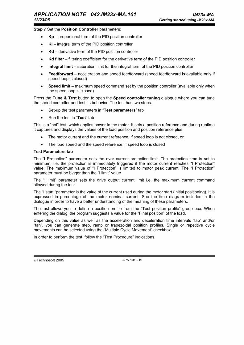
Step 7 Set the Position Controller parameters:
• Kp – proportional term of the PID position controller
• Ki – integral term of the PID position controller
• Kd – derivative term of the PID position controller
• Kd filter – filtering coefficient for the derivative term of the PID position controller
• Integral limit – saturation limit for the integral term of the PID position controller
• Feedforward – acceleration and speed feedforward (speed feedforward is available only if speed loop is closed)
• Speed limit – maximum speed command set by the position controller (available only when the speed loop is closed)
Press the Tune & Test button to open the Speed controller tuning dialogue where you can tune the speed controller and test its behavior. The test has two steps:
• Set-up the test parameters in “Test parameters” tab
• Run the test in “Test” tab
This is a “hot” test, which applies power to the motor. It sets a position reference and during runtime it captures and displays the values of the load position and position reference plus:
• The motor current and the current reference, if speed loop is not closed, or
• The load speed and the speed reference, if speed loop is closed
Test Parameters tab
The “I Protection” parameter sets the over current protection limit. The protection time is set to minimum, i.e. the protection is immediately triggered if the motor current reaches “I Protection” value. The maximum value of “I Protection” is limited to motor peak current. The “I Protection” parameter must be bigger than the “I limit” value
The “I limit” parameter sets the drive output current limit i.e. the maximum current command allowed during the test.
The “I start “parameter is the value of the current used during the motor start (initial positioning). It is expressed in percentage of the motor nominal current. See the time diagram included in the dialogue in order to have a better understanding of the meaning of these parameters.
The test allows you to define a position profile from the “Test position profile” group box. When entering the dialog, the program suggests a value for the “Final position” of the load.
Depending on this value as well as the acceleration and deceleration time intervals “tap” and/or “tan”, you can generate step, ramp or trapezoidal position profiles. Single or repetitive cycle movements can be selected using the “Multiple Cycle Movement” checkbox.
In order to perform the test, follow the “Test Procedure” indications.

APPLICATION NOTE 042.IM23x-MA.101 IM23x-MA 12/23/05 Getting started using IM23x-MA
©Technosoft 2005 APN.101 - 20
Figure 16 Position Controller Tuning Test – Test Parameters tab
Test tab
Check the position controller parameters. If the position control is done without closing the speed loop (see Step 1) the position controller tuning depends on the total inertia of your system. In the “Tuning” group box, verify the ratio (load inertia / motor inertia) or the total inertia. If you are not sure about these values, press “Identify” button to estimate the total inertia via the Total Inertia Test.
The Total Inertia Test is a “hot” test, which applies power to the motor. The test must be executed only after performing the current controller tuning. The test injects a current in the motor and measures its acceleration. Based on these data, and the motor torque constant, computes the total inertia of the system as seen at the motor shaft.

APPLICATION NOTE 042.IM23x-MA.101 IM23x-MA 12/23/05 Getting started using IM23x-MA
©Technosoft 2005 APN.101 - 21
Figure 17. Total Inertia Test
If the total inertia detected differs from the one set in the Drive Setup dialogue, you’ll be asked to validate the result when test dialogue is closed. If you agree, the newly obtained value will replace the previous parameter.
Press the “Tune” button. This sets the controller parameters according with the pass-band chosen, your motor data and the total inertia value.
You have 2 options to get the test results: as an “On-line plot” or as a “Data logger” plot.
In the “On-line plot” option, the load position and the position reference are continuously read from the intelligent motor and displayed in a control panel. This option is recommended if you set a repetitive cycle as position reference and plan to tune the controller on-the-fly while motor is moving.
In the “Data logger” option, the values of the load position and position reference plus: either the motor current and the current reference (when position control is done without closing the speed) or the load speed an the speed reference (when position control is done closing the speed loop) are saved in the intelligent motor memory, then uploaded and displayed in a data logger window. This procedure provides very precise data that can be analyzed with all the data logger facilities, but can’t be used to tune on-the-fly the controller. Therefore “Data logger” option is recommended more like a checking tool, to validate the tuning done in the “on-line plot” mode.
If you choose “On-line plot”, press the Start button. The test will run until you press the Stop button. You may freeze the control panel operation by pressing the “Pause” button and resume its normal operation with the “Play” button. If you choose “Data logger” press the Start button and

APPLICATION NOTE 042.IM23x-MA.101 IM23x-MA 12/23/05 Getting started using IM23x-MA
©Technosoft 2005 APN.101 - 22
wait until the test ends or until the data acquisition memory fills up (the maximum no. of data acquisition points is product specific)
Figure 18. Position Controller Tuning Test – Test tab
If needed, adjust the controller parameters and repeat the test by pressing the Start button again.
You can change the controller parameters by modifying their value in the corresponding edit boxes or by dragging the associated slider. When using the “on-line plot” mode, you can do this operation on the fly while the motor is moving. The min/max range of a slider is a sub-range of the absolute range, which is between:
• 0 and 2048 for Kp (proportional term), Ki (integral term), Kd (derivative term) and the speed feedforward
• 0 and 100 for the Integral limit. • 0 and 4194300 for the acceleration feedforward

APPLICATION NOTE 042.IM23x-MA.101 IM23x-MA 12/23/05 Getting started using IM23x-MA
©Technosoft 2005 APN.101 - 23
Test validation
The test is validated through visual inspection of the results presented graphically. If the motor position follows the position reference with acceptable performances (response time, overshoot, steady-state and following error), you can validate the controller coefficients, otherwise, change their parameters and execute the test until the results are satisfactory.
Figure 19. Position Controller Tuning Test – Test result
Test failure
If the test fails, do the following: • Check the current controller tuning. Use for example the Current Controller Tuning Test. • Check the total inertia value. Use for example the Total Inertia Test • Check the speed controller tuning if position control is done with speed loop closed. Use for
example the Speed Controller Tuning Test. Note that in this case the speed loop pass band must be at least 5 times higher then the position loop bandwidth.
• Check the position controller tuning. If position control is done without speed loop closed, start with a pass band around 100 rad/s and press the Tune button. If the position control is
APPLICATION NOTE 042.IM23x-MA.101 IM23x-MA 12/23/05 Getting started using IM23x-MA
©Technosoft 2005 APN.101 - 24
done with speed loop closed, use a pass band at least 5 times lower compared with that set for the speed loop and press the Tune button. For example if the speed loop pass band is 200 rad/s, the position loop pass band must be 20-40 rad/s
• Check “I Protection” level. It should be above the “I limit” • Check error register MER from the Drive status control panel for other errors
Press the button Ok to save the actual values of the controller parameters and return to the Drive dialogue. Press the button Cancel to leave unchanged the controller parameters and return to the Drive dialogue.
Step 7. In the “Protections” group-box, select and parameterize those protections that you want to be activated during the motion. For a first evaluation, use the default settings and selections.
Step 8. Specify the Inputs polarity
Enable – when this input is active, the intelligent motor is enabled. The active level is programmable. To execute the setup tests, the active level must set on: Enabled after power on.
Limit switch(+/-) – when any of these 2 inputs is activated, the intelligent motor enters in quick stop mode. The active level is programmable. In order to execute the setup tests, these inputs must be set to the inactive level
Step 9. Specify the Start mode for motors controlled with sinusoidal commutation
Move till aligned with phase A – The motor moves until it is aligned first with phase B, then with phase A. Set up the current to use during the motor start (as percentage of the nominal current) and the time needed to stabilize after the alignment with each phase.
Direct using Hall sensors – may be used if the motor is equipped with digital Hall sensors. In this case, the motor starts directly in trapezoidal mode and commutes to sinusoidal mode after the first transition of the Hall sensors.
Remark: The start mode selection is needed only if the motor is controlled like a PMSM with sinusoidal commutation
Step 10. Set/change axis ID
Select the Axis ID for the intelligent motor. Choose H/W (hardware) to read the Axis ID from the hardware switches for axis ID setting. If your drive has no hardware switches for Axis ID, the option H/W sets the default Axis ID which is 255. Choose any other value to impose an Axis ID, regardless of the Axis ID switches. The selected Axis ID will become effective after downloading the setup data and resetting the drive.
Note: At power on, the axis ID is set using the following algorithm:
a. With the value read from the EEPROM setup table containing all the setup data b. If the setup table is invalid, with the last axis ID value read from a valid setup table c. If there is no axis ID set by a valid setup table, with the value read from the hardware
switches/jumpers for axis ID setting d. If the drive/motor has no hardware switches/jumpers for axis ID setting, with the default axis
ID value which is 255.

APPLICATION NOTE 042.IM23x-MA.101 IM23x-MA 12/23/05 Getting started using IM23x-MA
©Technosoft 2005 APN.101 - 25
Press the Ok button to keep all the changes regarding the motor and drive setup. Press the Cancel button to exit without keeping the changes. Press the Motor Setup button to return to Motor Setup dialogue.
4. Download the setup to the intelligent motor
Press the Download to Drive/Motor button to download your setup data in the motor EEPROM memory in the setup table. From now on, at each power-on, the setup data is copied into the drive/motor RAM memory which is used during runtime. It is also possible to save the setup data on your PC and use it in other applications. Note that you can upload the complete setup data from a drive/motor.
To summarize, you can define or change the setup data of an application in the following ways:
• create a new setup data by going through the motor and drive dialogues • use setup data previously saved in the PC • upload setup data from a drive/motor EEPROM memory
5. Program motion
Programming motion on a Technosoft intelligent motor means to create and download a TML (Technosoft Motion Language) program into the motor memory. The TML allows you to:
• Set various motion modes (profiles, PVT, PT, electronic gearing or camming, etc.)
• Change the motion modes and/or the motion parameters
• Execute homing sequences
• Control the program flow through:
• Conditional jumps and calls of TML functions
• TML interrupts generated on pre-defined or programmable conditions (protections triggered, transitions on limit switch or capture inputs, etc.)
• Waits for programmed events to occur
• Handle digital I/O and analogue input signals
• Execute arithmetic and logic operations
• Perform data transfers between axes
• Control motion of an axis from another one via motion commands sent between axes

APPLICATION NOTE 042.IM23x-MA.101 IM23x-MA 12/23/05 Getting started using IM23x-MA
©Technosoft 2005 APN.101 - 26
• Send commands to a group of axes (multicast). This includes the possibility to start simultaneously motion sequences on all the axes from the group
• Synchronize all the axes from a network
In order to help you create a TML program, EasyMotion Studio includes a Motion Wizard. This offers you the possibility to program all the motion sequences using high level graphical dialogues which automatically generate the corresponding TML instructions. With Motion Wizard you can develop motion programs using almost all the TML instructions without needing to learn them.
The Motion Wizard is automatically activated when you select “M Motion” in the project window left side. When activated, Motion Wizard adds a set of toolbar buttons in the project window just below the title. Each button opens a programming dialogue. When a programming dialogue is closed, the associated TML instructions are automatically generated. Note that, the TML instructions generated are not a simple text included in a file, but a motion object. Therefore with Motion Wizard you define your motion program as a collection of motion objects.
Figure 20. Main section of the TML program
As a starting point, push for example the left most Motion Wizard button, Motion – Trapezoidal profiles. The programming dialogue allows you to program a position or speed profile with a trapezoidal shape of the speed, due to a limited acceleration.

APPLICATION NOTE 042.IM23x-MA.101 IM23x-MA 12/23/05 Getting started using IM23x-MA
©Technosoft 2005 APN.101 - 27
Figure 21. Motion – Trapezoidal Profiles dialog
Set a position or speed profile and then press the button. At this point the following operations are done automatically:
• A TML program is created by inserting your motion objects into a predefined template • The TML program is compiled and downloaded to the intelligent motor • The TML program execution is started
5. Evaluate motion application performances
EasyMotion Studio includes a set of evaluation tools like the Data Logger, the Control Panel and the Command Interpreter which help you to quickly measure and analyze your motion application. Details about the evaluation tools are presented in EasyMotion Studio on-line help.
.

APPLICATION NOTE 042.IM23x-MA.101 IM23x-MA 12/23/05 Getting started using IM23x-MA
©Technosoft 2005 APN.101 - 28
Drive layout:
IM23X - MA
J3J1
J2
159 6
1 5
10611 15
1
3
Figure 29. IM23x-MA drive layout