Embed Size (px)
Citation preview
~ PHOTOGRAPH THIS SHEET
w LIVEL INVENTORY
z
j EeDS SYPo/P S p#P5NdPDOUMENT% RJETFCAT]N jg
0 "P (pow '-7om" ow IsB
DISTRIBUTION STATEMENT
ACCESSION FORNTIS GRA&T
DTIC TAB
UNANNOUNCED E5 iTiCJUSTIFICATION j;g4,E1319T 9
BYDISTRIBUTION /AVAILABILITY CODES
DIST AVAIL AND/OR SPECIAL l
DATE ACCESSIONED
DISTRIBUTION STAMP
DATE RETURNED
89 9 11 099DATE RECEIVED IN DTIC REGISTERED OR CERTIFIED NO.
PHOTOGRAPH THIS SHEET AND RETURN TO DTIC-FDAC
OTIC FORM 70A DOCUMENT PROCESSING SHEET PREVIOUS EDITION MAY BE USED UNTILMAR 86 STOCK IS EXHAUSTED.
15th LEEDS-LYON SYMPOSIUM ON TRIBOLOGY
I-
N "THE TRIBOLOGICAL DESIGN OF MACHINE ELEMENTS"
I0SEPTEMBER 6th - 9th 1988
DEDICATED TO THE LATE PROFESSOR F T BARWELL
INSTITUTE OF TRIBOLOGY
DEPARTMENT OF MECHANICAL ENGINEERING
UNIVERSITY OF LEEDS
SYNOPSES OF PAPERS
SESSION 1 (Paper (i)) - TUESDAY 6th SEPTEMBER
KEYNOTE ADDRESS
THE TRIBOLOGICAL DESIGN OF MACHINE ELEMENTS
by
H S Cheng
(Walter P Murphy Professor of Mechanical Engineering)
(Northwestern University Evanston U S A)
The history of tribology indicates that many important tribological
concepts and theories were stimulated by the needs of new machinery development, and
the new tribological research findings, in turn, have helped to upgrade the design
of more efficc-nt and more reliable tribological elements. This mutual dependence
is illustrated with some classical and recent examples.
Discussions are then given to the status of tribological design limits of
counterformal as well as conformal contacts, and to the current needs to extend
these limits to meet the requirements of future machineries in aerospace.
automotive, and information processing industries.
SESSION II (Paper (i)) - WEDNESDAY 7th SEPTEMBER 1988
TRIBOLOGICAL DESIGN - THE AEROSPACE INDUSTRY
by
J Dominy
(Rolls-Royce plc, Derby, U K)
SYNOPSIS
The industrial definition of tribology tends to be somewhat wider than theclassical "study of friction and wear". The interest of the industrialtribologist will extend beyond the behaviour of the contact itself to considerheat generation, cooling, component stressing and life.
In the case of the aero engine the most prominent tribological problem isbearings. The combination of load, speed and environment have caused thedesigner to use tool steels to meet the required life. A less obvioustribological application is that of the rubbing blade tip seals on ccmpressorswhere any excessive wear directly affects the engine performance.
Gearboxes are common to both helicopters and turbo-prop engines. Theapplications are very different due to the very high ratio required for ahelicopter and the different safety requirements since, in the case of thehelicopter, the gearbox is fundamental to its operation. Efficiency hasbecome of extreme importance in the aero engine gearbox, especially those forthe very large (60,000 hp) engines projected for the next century. Theweight, bulk and drag of the necessary cooling system are such that theconcept only becomes viable if the losses can be maintained at less than 0.75%throughout the flight cycle.
It must be said that in most gearboxes and bearings, tribological design is asecondary consideration. This is partly due to the constraints placed on thedesigner by the environment and available lubricants but mainly to therequirement for the component not to suffer from major structural damage whichis usually immediate, rather than surface damage, which can often be detectedand is generally a more benign failure.
The tribology of airframes has tended to c '- round flight controls andcontrol bearings. Here again the rotary Lr. . :'ed wing applications aredifferent due to the requirement of the heli, - to transfer the controlmotion to the rotating blades. Tyres and brakes .-e continually developing asthe weight and speed of large transport aircraft continues to increase.
Engine and gearbox lubricants have really only changed in detail in recenttimes due to the constraints of the specifications to which they aremanufactured, the qualification requirements for any new lubricant andoperator acceptance. Nevertheless, they are approaching their limits in termsof temperature capability and any significant improvement will necessitate newbase stocks.
1s
Industrial research into tribology has traditionally been in close associationwith the academic world, primarily due to the development of the principles oflubrication, particularly ehl, within the universities while the aerospaceindustry has applied the new science to its particular problems. Thisco-operation will continue but the restrictions on funding from bothindustrial and academic sources will mean increased selectivity and greaterdifficulty in supporting fundamental work.
f 7
SESSION II (Paper (ii)) - WEDNESDAY 7th SEPTEMBER 1988
TRIBOLOGICAL DESIGN - THE RAILWAYS
by
C Pritchard and T G Pearce
(British Railways Board, Derby U K)
SYNOPSIS
Introduction
In a paper reviewing the tribological aspects of railways, F T Barwell
identified 47 interacting surfaces. Most are common to other industries butone, the interaction between steel wheel and steel rail, remains unique and
fundamental to railways. An understanding of this interaction is crucial tomany design processes, and forms the subject of this paper.
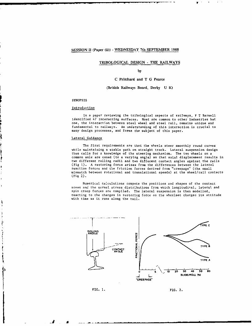
Lateral Guidance
The first requirements are that the wheels steer smoothly round curves
while maintaining a stable path on straight track. Lateral suspension designthus calls for a knowledge of the steering mechanism. The two wheels on a
common axle are coned (to a varying angle) so that axial displacement results in
two different rolling radii and two different contact angles against the rails(Fig 1). A restoring force arises from the differences between the lateralreaction forces and the friction forces derived from "creepage" (the small
mismatch between rotational and translational speeds) at the wheel/rail contacts(Fig 2).
Numerical calculations compute the positions and shapes of the contact
areas and the normal stress distributions from which longitudinal, lateral andspin creep forces are compiled. The lateral suspension is then modelled,
reacting to the changes in restoring force as the wheelset changes its attitude
with time as it runs along the rail.
YPE C
ROLNGRADIUS I
0
L,
z TYPE B---- CONTACT
TYPE A
0 0 2 4 0 60A SLIDEIROLL (%)
'CREEPAGE'
FIG. 1. FIG. 2.
&-
Measurements of Creepage
Measurements show that theoretical creep forces are approximately
attained, even though the calculations assume that the friction coefficient increepage is p=0.60 and the measured friction coefficient ("adhesion") varied
from 0.40 to 0.15. It is suggested that the sliding conditions in "microslip"
are different from those in the higher slip generated in adhesion measurements.
Wear
A requirement of the design process is to minimise wheel/rail wear. A
wear number is invoked, the creep force T(Newtons) times the creepage Y. It is
found that the wear rate of rails is proportional to TY over two ranges. For TY
less than 200N wear is mild, above this value wear increases by a factor of 10and debris is metallic. Water prolongs mild wear to TY's approaching 1000,
while oils reduce mild wear by a factor of 10.
Surface Defects/Corrugations
As i.- a11 rolling contact devices, surface damage occurs other than wear.
On rails, cracks form by a mechanism of rolling contact fatigue, initiating atsmall areas of local deformation ("squats") in the rail surface, sometimes at"corrugations" which fo-:. in a periodic wear pattern with a wavelength of40-80mm.
Corrugations also cause noisy running. It is postulated that they are
initiated by a stick-slip lateral motion of the rail, excited by a misalignedwheelset. This results in a periodic pattern of abrupt wear scars, each about
30mm long. The pattern becomes established if a vertical vibration of the railis excited in phase with the scar spacing, and it is found that a spacing of
twIce the scar lentch gives rise to the largest vertical force fluctuations.Thus, when the natural frequency of vertical vibration, combined with traffic
speed, provides a "wavelength" of about 60mm, corrugations are formed.
Braking and Traction
Braking and traction make considerable demands on the adhesion coefficient,
which ranges between about 0.40 and 0.10, with occasional excursions down to
0.07 (0.02 on damp, rusty or leaf affected track). When adhesion is inadequate,
control systems in the past have "dumped" power so as to prevent wheel or raildamage. More recently, wheel slide protection (WSP) and traction controldevices are designed not only to prevent damage but also to control the
slide/roll ratio where friction is highest. Some assume an optimum slide ratio,
some "peak seek'. Measurements of the friction characteristics show at leastthree types of behaviour (Fig 2), and friction is also increased by"conditioning" in sustained high slip. The way in which control should respond
to such a diverse pattern is a current topic for debate.
Conclusions
A considerable tribological understanding of the interactions at the wheel/rail
interface is required if the design of railway running gear and of braking andtraction control is to be properly optimised.
SESSION 11 (Paper (iii)) - WEDNESDAY 7th SEPTEMBER
TRIBOLOGICAL DESIGN - THE AUTOMOTIVE INDUSTRY
by
P A Willermet
(Ford Motor Co. Dearborn, U S A)
SYNOPSIS
Rapid and continuing change within the automotive industry demands
continual improvement in the quality, performance and reliability of vehicles. At
the same time. competitive forces demand shorter product cycle times and new
organizational approaches to the design process. The introduction of new
technology and increased reliance on suppliers demand better methods of evaluating
designs and materials. All of these factors lead to increased opportunities for
the introduction of improved tribological design methods as well as the
introduction of improved designs and materials.
SESSION 11 (Paper (iv)) - WEDNESDAY 7th SEPTEMBER 1988
TRJBOLOGICAL DESIGN - THE PROCESS INDUSTRY
by
J D Summers-Smith
(Consultant, Guisborough U K)
SYNOPSIS
The cne-Acal process industry does not normally design its own machines,a s to purchane what is available in the market place. Such
=i e .4ll ve *,en proved rn the manufacturer's test bed, but this
is a 3omewhat idealised s tuation well removed from the real operationalenvironment where the machine will be subject to the full processcondit-cns, seldom possible to realise on the test bed, as well as to
process uzsets, operational malpractice, gradual deterioration in
service and other factors, probably unforeseen, outside those specified
in the original purchase enquiry.
if failures are to be remedied, and in the context of this Symposium we
are concerned with those affecting tribological components, the usermust have a full understanding of the design and operation of such
ocmpocentt 4n order that the true failure mechanism can be identified.Full cooperation with the original designer is necessary to obtain a
feasible solution; however, before this is forthcoming it may even benecessary to convince the manufacturer by a suitable analysis and
presentation of the facts that there is a genuine design fault and thatfailure is not merely the result of the maloperation of his machine.
Examples are given in the full paper of actual machine problems that
have occurred in the chemical industry. These examples are concernedwith boundary lubrication, load calculation, chemical attack of
triboiogical components and bearing influenced rotor dynamics and haveoeen chosen specifically both to highlight different tribological
mechanisms and to illustrate the depth of analysis necessary to identify-he raLse of failure and obtain a satisfactory solution. These case
srudtes show the need for a full understanding of the machine and the
fur,-tinning of the machine elements that is crucial in developing the
nee'-- ar-v iegree -)f cooperation hetween the user and designer and show,he role of the machine user in tnis process.
days are discussed Jn which the Knowledge gained from the analysis of
such -. perating experience can be disseminated and used to influence newcesigrs in order t achieve enhanced reliability and predictability ofperformance of tribological machine elements. A brief look is given at
future problem areas in tribology that are likely to become of
significance in machines for the process industries.
SESSION III (Paper (i) - WEDNESDAY 7th SEPTEMBER 1988
DESIGN OF CONTROLLABLE MECHANICAL SEALS
by
R F Silant (Georgia Institute of Technology, U S A)
0 Giles, W E Key (BW/IP International Inc., U S A)
SINXOPSiS
Modern noncontacting mechanical seals operate with a thin lubricating film offluid between the seal faces. Conventional seals are designed such that this film is of
optauam -hiickae.s at a single steady state design point. However, since most seals mustoperate over a range of steady state conditions and a variety of transients, theyexperience frequent periods during which the film thickness is too small, and frequentperiods during which it is too large. The former lead to mechanical contact betweenthe faces resulting in face damage, excessive wear, and decreased reliability, while thelatter lead to periods of excessive leakage.
Basic Concept
The above problems can be alleviated with a seal in which the thickness of thelubricating film is electronically controlled. A microcomputer-based control system andactuator continuously adjust the film thickness, based on information received from asensor which monitors conditions in the film. The control system sets the film thicknessat an optimum value and responds to changes in operating and environmentalconditions so that the film thickness is kept at an optimum value, and both face contactand excessive leakage are prevented.
The film thickness is adjusted by an electromechanical actuator which exerts aforce on the backside of the nonrotating seal face. This causes the face to deform, andthe sealing surface to cone in the radial direction (on the order of microns).
The shape of the pressure distri.ution in the fluid film is strongly dependent onthe amount of coning, and that pressure distribution produces the "opening force" which
keeps the film intact and determines film thickness. The larger the amount of coning,the more convex the pressure distribution, the larger the instantaneous opening force,and the larger the steady state film thickness.
I
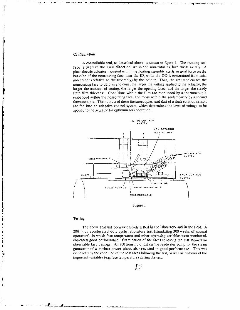
Confizuration
A controllable seal, as described above, is shown in figure 1. The rotating sealface is fixed in the axial direction, while the non-rotating face floats axially. Apiezoelectric actuator mounted within the floating assembly exerts an axial force on thebackside of the nonrotating face, near the ID, while the OD is constrained from axialmovement (relative to the assembly) by the holder. Thus, the actuator causes thenonrotating face to deform and cone; the larger the voltage applied to the actuator, thelarger the amount of coning, the larger the opening force, and the larger the steadystate film thickness. Conditions within the film are monitored by a thermocoupleembedded within the nonrotating face, and those within the sealed cavity by a secondthermocouple. The outputs of these thermocouples, and that of a shaft rotation sensor,are fed into an adaptive control system, which determines the level of voltage to beapplied to the actuator for optimum seal operation.
TO CONTROLSYSTEM
NON-ROTATiNG
FACE HOLDER
f , I SYSTEM
SHAFTFROM CONTROL
SROTATING FACE NON-ROTATING FACE
! THERMOCOUPLE
Figure 1
Testing
The above seal has been extensively tested in the labortory and in the field. A200 hour accelerated duty cycle laboratory test (simulating 300 weeks of normaloperation), in which face temperature and other operating variables were monitored,indicated good performance. Examination of the faces following the test showed noobservable face damage. An 800 hour field test on the feedwater pump for the steamgenerator of a nuclear power plant, also resulted in good performance. This wasevidenced by the condition of the seal faces following the test, as well as histories of theimportant variables (e.g. face temperature) during the test.
.'
SESSION III (Paper ii) - WEDNESDAY 7th SEPTEMBER 1988
MICRO-ELASTOHYDRODYNAMIC LUBRICANT FILM FORMATION
IN ROTARY LIP SEAL CONTACTS
t by
A Gabelli
(SKF Engineering & Research Center B V, Nieuwegein, The Netherlands)
SYNOPSIS
1. Introduction
This paper examines the characteristics of the lubricant film* developed under rotary lip seals. It has recently been shown
exper,.entaily (I) that these types of seals may operate withdifferent regimes of lubrication varying from simple boundaryconditions to full film formation. The mechanics of the lubricantfi!m built up between apparently parallel surfaces is stillcontroversial (2). There are however strong experimentalindications (1) supporting the idea of film formation arisingfrom the EhD action of colliding asperities at the sealinginterface.
In the present study a theoretical understanding of rotary lipseals lubrication is attempted by analyzing the EHD contributionnf the asperities in virtual contact. In addition also theposlt:ve hydrodynamic pressure originated by the wavy morphologyof the sealing surfaces is evaluated.
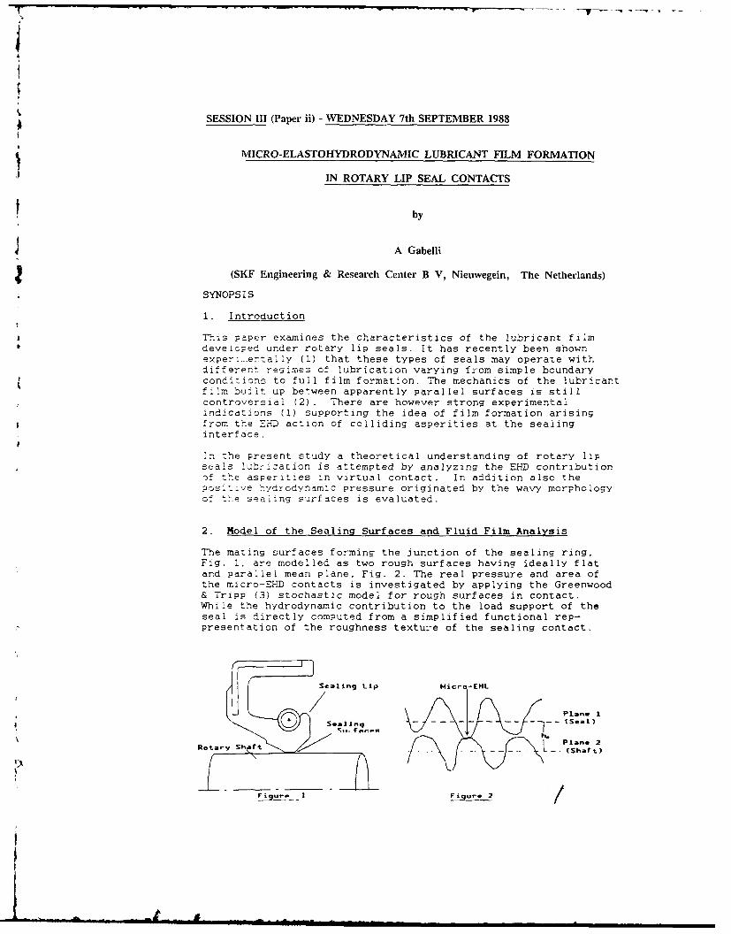
2. Model of the Sealing Surfaces and Fluid Film Analysis
The mating surfaces forming the junction of the sealing ring,Fig. 1, are modelled as two rough surfaces having ideally flatand parallel mean plane, Fig. 2. The real pressure and area ofthe micro-EHD contacts is investigated by applying the Greenwood& Tripp (3) stochastic model for rough surfaces in contact.While the hydrodynamic contribution to the load support of theseal is directly computed from a simplified functional rep-presentation of the roughness texture of the sealing contact.
Sealing Lip Micro-EHL
Plane I+ S ,all q (seal)
Rotay Shrt LPlano 2Ro t - -- (Shaft)
j. et
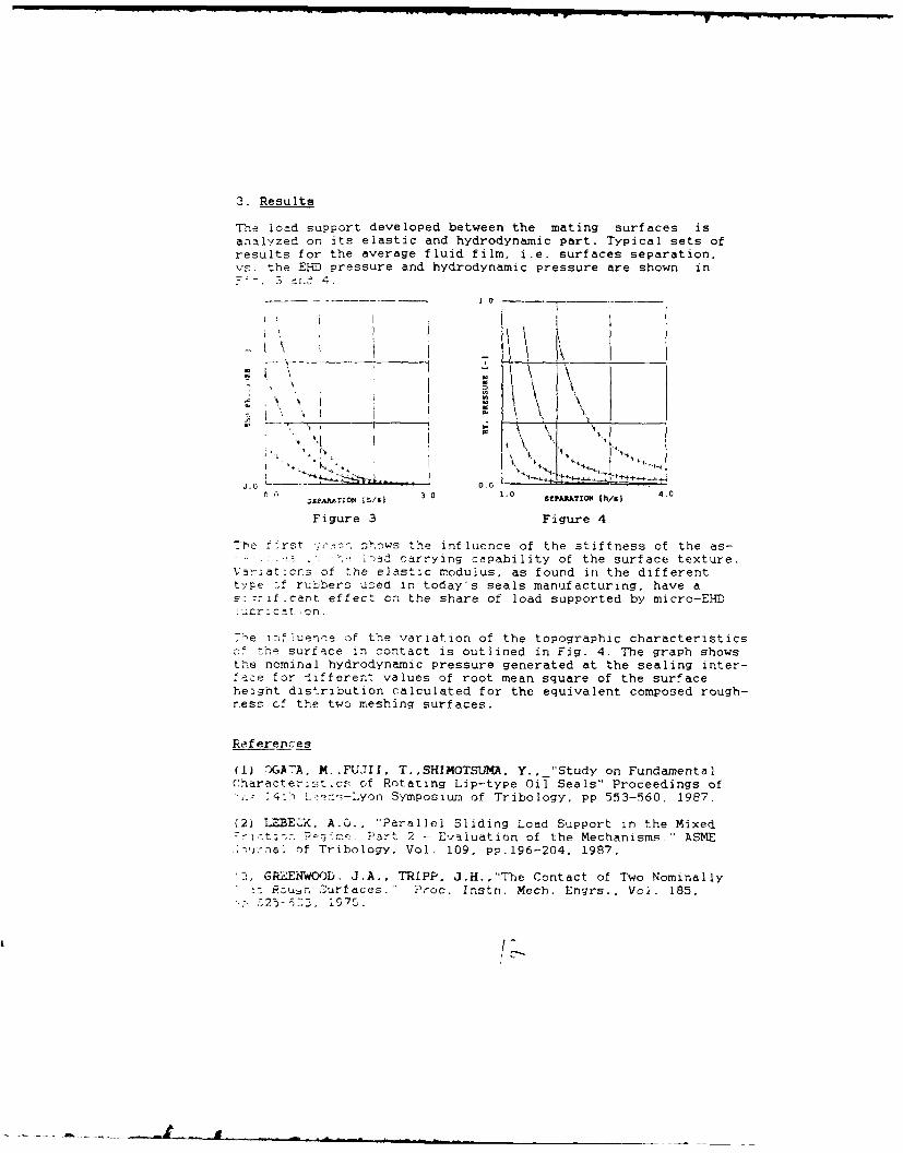
3. Results
The load support developed between the mating surfaces isanalyzed on its elastic and hydrodynamic part. Typical sets ofresults for the average fluid film, i.e. surfaces separation.vs. the EHD pressure and hydrodynamic pressure are shown in
0 -------- 4 .
1.1
N ~\
I \ \
J.0 0 00C , AA. ION 1 3.0 1.0 SEPRATION t/9I 4.0
Figure 3 Figure 4
Tbe f:rst - shows the influence of the stiffness of the as-. )ad carrying capability of the surface texture.
Varaat:crs of the elastic modulus, as found in the differenttype .f rubbers used in today's seals manufacturing, have as: -if.cart effect on the share of load supported by micro-EHID!,'zrlcat eon.
7-e influence of the variation of the topographic characteristics-.' the surface in contact is outlined in Fig. 4. The graph showsthe nominal hydrodynamic pressure generated at the sealing inter-face for different values of root mean square of the surfaceheight distribution calculated for the equivalent composed rough-ness ef the two meshing surfaces.
References
(1) r)GA7A, M.,FUJII, T.,SHIMOTSUMA, Y.,_ "Study on FundamentalCharacterist,c : of Rotating Lip-type Oil Seals" Proceedings of1, . - _,-Lyon Symposium of Tribology, pp 553-560, 1987.
(2) L_ BEC, A.6., "Parallel Sliding Load Support in the Mixed- - t-<. Part 2 - Evaluation of the Mechanisms.' ASME
, of Tribology, Vol. 109, pp.196-204, 1987.
'T GREENWOOD. J.A., TRIPP, J.H.,"The Contact of Two NominallyP,7Ru~n Zurfaces." Proc. Instn. Mech. Engrs., Vol. 185,;. 25- [Y2 1970.
jc,7S.
C_
SESSION III (Paper (iii)) - WEDNESDAY 7th SEPTEMBER 1988
LUBRICATION OF RECIPROCATING SEALS: EXPERIMENTS ON THE INFLUENCE OF
SURFACE ROUGHNESS ON FRICTION AND LEAKAGE
by
A F C Kanters and M Visseher
(Eindhoven University of Technology, The Netherlands)
SkOPSIS
Introduction
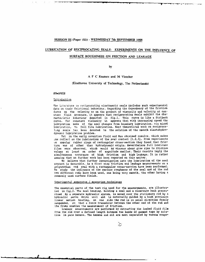
The iiterature on reciprocating elastomeric seals includes much experimentaldata on teir frictional behaviour. Regarding the dependency of the frictionforce on the velocity or on the product of viscosity and velocity at con-stant fluid pressure, it appears that reciprocating seals exhibit the cha-racteristic behaviour depicted in fig.l. This curve is like a Stribeckcurve. For constant viscosity it appears that with increasing speed thelubrication mode of the seal changes from boundary lubrication, via mixedlubrication, to full film lubrication. Most theoretical work on reciproca-ting seals has been devoted to the solution of the smooth elastohydro-dynamic lubrication problem.
Yet in the early seventies Field and Kau obtained results, which makesone reflect on the lubrication of the seal contact [1,2,3). From experimentson annular rubber rings of rectangular cross-section they found that fric-tion was of other than hydrodynamic origin. Nevertheless full lubricantfilms were observed, which would by viscous shear give rise to frictionvalues at least an order of magnitude smaller. Their results imply thesimultaneous occurance of high friction and high leakage. It is ratheramazing that no further work has been reported on this matter.
We believe that further investigation into the lubrication of the sealcontact is desirable. As a first step friction and leakage measurements on apolyurethan rod seal with a rectangular cross-section have been performed.To study the influence of the surface roughness of the seal and of the rodtwo different rods have been used, one being very smooth, the other having acommonly used surface finish.
Experimental apparatus / measuring techniques
The essential parts of the test rig used for the measurements, are illustra-ted in fig.2. The seal housing, holding a seal and a clearence bush pressu-rised by a separate hydraulic system, is moved over the stationary rod by ahydraulic servo drive unit and is externally guided by a high precisionlinear motion bearing. At one side the rod is in axial direction freelysuspended, so that a force transducer between the other end of the rod andthe frame enables the measurement of friction.
Leakage measurements are performed by extracting the leaked fluid filmfrom the rod over a defined length between two bands of gummed tape by solu-tion in pure hexane. The hexane and oil are next separated by vacuum evapo-
ration and the oil is weighed, so that the average thickness of the leakedfilm can be determined.
Test program
An identical test program has been performed for both rods. The first partof this program consisted solely of friction measurements in dependence ofpressure and velocity to establish friction curves as depicted in fig.l.The second part of the test program consisted of simultaneous measurementsof friction and leakage. The results enabled some conclusions to be drawn onthe lubrication of the seal contact.
I SEAL MOUSING
SLINEAR MOTION BEARINGN RANE
RODIAL SUSPENSION UITh FORCE TRANSOuC(k
6 4A0101 SUSPeVSiON
R CILINOE. OF 1" NAULIC SIRVO 34103 UNIT
fig.l characteristic- --.-.-
friction curve
fig.2 essential parts of the test rig
References
[1] Field, C.J., Nau, B.S., 'An experimental study of reciprocating seals',proceedings conference on elastohydrodynamic lubrication, organised byInst. Mech. Engrs., 1972, paper C5, 29-36
[2] Field, C.J., Nau, B.S., 'Film thickness and friction measurements duringreciprocation of a rectangular section rubber seal ring', 6th Int. Conf.on Fluid Sealing, organised by BHRA, 1973, paper C5, 45-56
[3] Field, C.J., Nau, B.S., 'The effects of design parameters on the lubri-cation of reciprocating rubber seals', 7th Int. Conf. on Fluid Sealing,organised by BHRA, 1975, paper Cl, 1-13
SESSION III (Paper iv)) - WEDNESDAY 7th SEPTEMBER 1988
RADIAL LIP SEALS, THERMAL ASPECTS
by
M J L Stakenborg and R A J van Ostayen
(Eindhoven University of Technology, The Netherlands)
SYNOPSIS.
In studying the sealing and lubrication mechanism of radial lip seals it is
important to know the influence of the seal-shaft contact temperature onthe contact conditions such as the contact force, the contact width and the
contact stress distribution. The influence of the contact temperature is
studied by a coupled temperature stress analysis employing the finiteelement method (FEM).
The contact temperature resulting from dissipated friction heat wascalculated using the thermal network method (TNM).
The contact temperatures were measured on a test rig using 3 differentmeasurement techniques.
FEM ANALYSIS.
Using a coupled temperature-stress FEM analysis, the following temperatureeffects on the static seal-shaft contact conditions were studied : (1)
change in seal material stiffness, (2) change in garter spring stiffness,(3) expansion of the seal material and (4) expansion of the shaft.
TNM ANALYSIS.
The seal-shaft contact temperature which results from a certain dissipatedfriction heat depends on the heat balance in the entire machine. Thethermal network method is an appropriate method to calculate the (contact)
temperatures which will occur in seal applications in practice. In thethermal network method a machine is divided into a network of thermal
components such as heat resistors, capacitors and sources. The TNM is aneasy to conceive and flexible method, which does not demand expensive
software and hardware like the FEM.
EXPERIMENTS.
Because of the small dimensions of the contact width b (in practice 0.05 <b < 0.5 mm) it is difficult to measure the temperatures inside the contact.Three different experimental techniques ( NTC thermistors, thin film
transducers and infra-red measurements) were employed to measure the
seal-shaft contact temperatures on a test rig.
RESULTS.
(1) The contact temperature Tc has only a minor influence on the static
contact conditions of a rubber lip seal for 0 < Tc< 100 0C.(2) Good correspondence was found between the contact temperaturescalculated using the TNM and the temperatures measured on a test-rig for
both transient and steady-state situations.
REFERENCES.
[1] Upper, G. 'Dichtlippentemperatuur von Radial-Wellen Dichtringen.'
Ph.D. Thesis, Univ. of Karlsruhe, Germany, July 21, 1967.(In German)
[2] Stakenborg, M.J.L. 'On the sealing and lubrication mechanism of radiallip seals.' Ph.D. Thesis, Eindhoven Univ. of Technology, Sept. 20,1988.
AOtLER BEARINGS LIP SEAL
SLIP RING UNIT ROTATING A[POST IC IEAAINOS MOU-ROIAIIRG AENOSIAIIC.1(A1IN G F ortIRMEASUACMNTS
Fig. 1 : Test-rig.
O]LF ILK
Q, 90.8% q Q,
SHAFT T. (TI120
0 A BULK O2L A-AI0R
4I0 5HEUSINTG
S S-SEAL so
OIL HOUSING
40
AIRGEARI;.m$
20
M043IS40 -N- 080*
33.7% 17.1% [9.S 38.1% 1.2% 900 1800 2700 3600 4500 5400
AAIBIENT AIRJa sw
Fig 2 : Sankey diagram Fig 3 : Transient contact
of heat flows in test-rig . temperatures.
I
.. ..... m~bm~ =' mwlwm dlw UUa
SESSION IV (Paper (i) - WEDNESDAY 7th SEPTEMBER
LUBRICATION AND FATIGUE ANALYSIS OF A CAM AND ROLLER FOLLOWER
by
B A Gecim
(General Motors Research Laboratories, Michigan, U S A)
SYNOPSIS
The lubrication characteristics of a cam and roller follower interface are* investigated. The governing kinematic and geometrical relationships are
incorporated with elastohydrodynamic lubrication analysis of concentratedcontacts. The loads at the interface are determined by the dynamic analy-sis of the overall valve train.
The specific topics analyzed in this study are: the lubricant film thick-ness including thermal and squeeze-film effects; maximum Hertzian pressuresand possibility of plastic flow; traction forces and possibility of grossslip; cam torque and valve train energy loss; fatigue life of severalrolling surfaces; parametric studies to improve film thickness, contactpressures, and fatigue life.
Sample Results
Figure 1 shows the lubricant film thickness around the cam circumferencefor two speeds. The representative composite-RMS-roughness value for thecam/follower pair is also indicated.
Film Thickness at3000 cam r/min
/ /' Film Thickness at250 cam r/min
/ RMS Roughness)) . .,.j0.5 micrometer
IF
FIGURE 1

The specific film thickness is much smaller than unity at low speeds, evenon the base circle, indicating boundary lubrication mode. At higherspeeds, especially on the base circle, conditions are closer to the mixedlubrication mode.
Figure 2 shows the traction coefficient at the cam/follower interface for ano-slip condition. The traction force provides the required accelerationto the roller and overcomes the bearing friction. At low rotationalspeeds, inertia of the roller is negligible and the only traction requiredis to overcome the needle bearing friction. At high rotational speeds, theroller inertia becomes important. In either case, because of operating inboundary and mixed lubrication modes, gross slip at the interface seemsunlikely.
Figure 3 shows the lubrication regimes at the cam/roller interface over onecomplete camshaft rotation at 3000 cam r/min. The operating conditions arein the elastohydrodynamic regime associated with heavily loaded contacts.At lower speeds, the elastic deformations become even more pronounced.
0.011 250 Cam rtmin
TractionCoefficient
0.005-
0 Elastic /
S -60 -30 0 o 30O 6 0 VariableCam Angle Vicst,!.U
0.ol.VariableViscosity
-0.0051 0
Traction 0Coefficient CD
Mo ... BElastic
' ! Isoviscous
I-0 -0 -0 0 30o 60 --oSCam Angle iRigid
-0.0- Isoviscous
300 10m 10 0 1 1
-0.10- ELASTICITY PARAMETER G3
FIGURE 2 FIGURE 3
0
I _ ... . -- - L " ll f n I l I I I n IITrII I I I IIn
SESSION IV (Paper (ii)) - WEDNESDAY 7th SEPTEMBER
PREDICTIONS OF CAM WEAR PROFILES
by
R H Fries and C A Rogers
(Virginia Polytechnic Institute and State University, U S A)
Synopsis
This paper describes a computational method for predicting the profiles into which camsand followers wear in service. The method is conceptually simple. The first step is tosolve the kinematic constraint problem for the cam and follower. This step determinesthe locations of the contact patch center on the cam and follower for all cam rotationangles. From these results, the follower displacement, velocity, and acceleration are de-termined. The next step is to solve the cam dynamics problem to obtain the normalforces at the contact patch. The tangential contact forces are determined assumingCoulomb or other friction conditions that may exist in the contact region. A simplewear model is then employed to estimate the localized wear as a function of the camangle.
The cam and follower profiles are modified according to the amount of wear estimated,and new cam and follower profiles are obtained. The process is repeated sequentiallyso that the continuous wear process is approximated by a number of discrete wear steps.The process is nonlinear because the cam dynamics depend upon the cam and followerprofiles.
This method has potential for predicting the shapes into which cams and followers willwear in service. The method is applicable to other mechanical components as well, andit has been applied to the wear process of rail vehicle wheels.
Cam Kinematics
When cams possess profiles that are described by simple analytical curves, cycloids,harmonics, and polynomials, for example, it is a straightforward matter to determine thefollower motion. A number of undergraduate texts describe analytical methods to solvethe cam kinematics problem. See Mabie and Reinholtz (1987) for example. When wearoccurs on a cam and its follower, then the solution of the cam kinematics problem is notso easy because the profiles are no longer described by simple curves.
For wear predictions, it is convenient to describe cams and followers by sets of pointslocated on their contacting surfaces. We developed a method of solving the kinematicsproblem for cams and followers so described. For a given cam position, the cam andfollower profile points are fit with splines, and the contact point is found by determiningthe intersection of the splines. Follower displacements are then obtained for one revo-lution of the cam. To obtain follower velocity, we least squares fit the displacementcurve and differentiate. Then we smooth the results. To obtain accelerations, we leastsquares fit the velocity results, and differentiate. We also smooth the accelerations re-sults. Our method was adapted from the work of Cooperrider et al. (1976), who solvedthe kinematic constraint problem for railway wheels on rails.
IA
For a given cam angular velocity, the above method provides follower displacement,velocity, and acceleration, and the location of the contact point on the cam anld followerfor any cam position.
We verified our kinematic solutions by comparing positions, smoothed velocities, andsmoothed accelerations obtained numerically to those obtained analytically for simplecam profiles. The results of our numerical method were quite good.
Cam Dynamics
In this work we have thus far assumed that a flat follower with a given mass is springloaded against the cam. The cam dynamics are therefore simple, and the normal contactforce can be computed easily once the cam kinematics solution is obtained. Morecomplex cam dynamics can be accommodated with an increase in computation time.
We have also assumed Coulomb friction conditions to exist at the contact patch. Thepresence of a lubricating film at the contact interface would influence the dynamics.This effect can also be accounted for, but it has not been included in the initial work.
Wear Model
We have assumed the wear process to be described by a simple wear model of theArchard (1953) type wherein wear is postulated to be proportional to normal load andsliding distance. The general method admits the use of essentially any wear model, andthe Archard model was used in this work for its simplicity.
For each increment of cam rotation, a wear volume is computed according to the wearmedel. The points describing the cam and follower profiles are then changed in pro-portion to the wear volume. 1 he process is repeated sequentially to simulate the con-tinuous wear process.
Results
The paper contains results of wear predictions for the simplified conditions discussedabove. As expected, wear rates are higher aL cam positions corresponding to highercontact loads. These results are intended to be illustrative of the wear computationmethod. We have made no attempt in this initial work to compare predicted wear pro-files to actual service worn profiles. These comparisons are the subject of future work.
References
Archard, J. F., 1953, "Contact and Rubbing of Flat Surfaces," Journal of Applied Phys-ics, Vol. 24, pp. 981-988.
Cooperrider, N. K., et al., 1976, "Analytical and Experimental Determination of Non-linear Wheel Rail Geometric Constraints," Symposium on Railroad Equipment Dynamics,ASME, pp. 41-70.
Mabie, H. H., and Reinholtz, C. F., 1987, Mechanisms and Dynamics of Machinery. JohnWiley & Sons, New York.
2
SESSION IV (Paper (iii)) - WEDNESDAY 7th SEPTEMBER
CAM AND FOLLOWER DESIGN
by
A D Ball, D Dowson and C M Taylor
(The University of Leeds U K)
SYNOPSIS
Software has been developed within the Department of Mechanical
Engineering at the University of Leeds which allows tribological
studies to be carried out upon any of the cam and follower designs in
common use in today's internal combustion engines. The program is
written in such a manner that it can easily be used by an, competent
professionai engineer.
The program uses analysis developed by Dyson and co-workers L1,2,3)
to determine the kinematics of the contacting cam and follower pair.
The loads at the :am/follower interface are determined by summing the
force compcnents arising due to tne friction at the interface, the
soring force and the inert-a of the reciprocating parts. Throughout
the analysis it is assumed that, apart from the spring, the valve
zrain components are rigid. The frictional forces and moments a: the
valve guide and follower pivot point (or follower bore) are igncred,
as is the load arising oue to the gas pressure upon the head of the
valve. Full details of the basis of the analyses involved will be
presented.
The program allows studies to be made of the effects of changes in
design parameters upon the tribological performance of the valve
train. Parametr.c studies have teen carried cut on several different
types of valve train layouts including those incorporating cams
ctnirg against end pivoted followers keg. as employed in the Ford
.,l1 Pinto engine currently used in the Sierra range) and cams acting
!gainst :entrally bivoted followers (eg. .s used in the Rover 2300
and 2600 engines). Table I shows some of the predicted benefits to be
gained by mal'ry smaili, realistic ,nanges tas sicwn in Taole 2) to
tne valve trains mentioned above.
The zcftware develcbment has oeen accompanied by an experimental
programme designed to *aiidate the analytical model.
9,
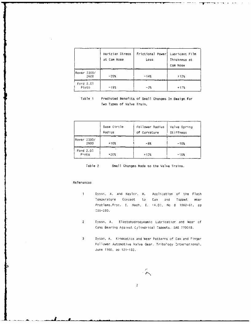
Hertzian Stress Frictional Power Lubricant Film
at Cam Nose Loss Thickness atCam Nose
Rover 2300/ C2600 -20% -14% +12%
Ford 2.01 I
Pinto - 19% -3% +17%
Table 1 Predicted Benefits of Small Changes In Design For
Two Types of Valve Train.
Base Circle Follower Radius Valve Spring
Radius of Curvature Stiffness
Rover 2300/ 1o12600 +10% -8% -10%
Ford 2.'01Pinto +20% +12%
Table 2 Small Changes Made to the Valve Trains.
References
1 Dyson, A, and Naylor. H. Application of the Flash
Temoerature Concept to Cam and Tappet Wear
Problems.Proc. I. Mech. E. 'A.D), No 8 1960-61, pp
255-280.
2 Dyson, A. Elastohydrodynamic Lubrication and Wear of
Cams Bearing Against Cylindrical Tappets. SAE 770018.
3 Dyson, A. Kinematics and Wear Patterns of Cam and Finger
Follower Automotive Valve Gear. Tribolooy International,
June 1980, op 121-132.
2
SESSION V (Paper (i)) - WEDNESDAY 7th SEPTEMBER
POWER TRANSMISSION BY FLAT, V AND TIMING BELTS
by
T H C Childs and I K Parker
(The University of Bradford, U K)
SYNOPSIS
This paper reviews aspects of current understanding of belt performance,relating for flat and V belts power loss and for timing belts tooth loading
to belt tension and torque transmission, to belt mechanical and friction
*properties and to pulley radius and angle of wrap.
Belt ConstructionModern belts are composite constructions, transmitting load through a stiff
tension member and traction through an elastomeric facing. Flat belts aremade in two main ways: either a strip tension member, usually cold drawn
t nylon, is bonded to a fabric previously roll coated with elastomer, and madeinto a loop by a welded lap joint; or a truly endless belt is made bywinding a nylon, polyester or glass fibre cord on to a cylindrical mandreland moulding a rubber carcass round it. V and timing belts are always made
by moulding a rubber carcass round a mandrel-supported cord; the drivingfaces of timing belts are reinforced by a textile cover but V belt faces are
not always so protected.
The ratio c of belt extension force to strain for a 2mm thick strip tensionmember flat belt is typically 1 kN per mm of belt width while for typical
automotive V and timing belts c is 5 to 10 kN/mm. Youngs modulus of beltelastomer carcasses is of the order of 10 MPa but can be anisotropic.
Friction coefficients between textile faced belts and dry pulleys are about
0.2 to 0.35and for belts without a textile cover are between 0.4 and 0.9.
Power Loss Preliminaries - Flat and V Belts
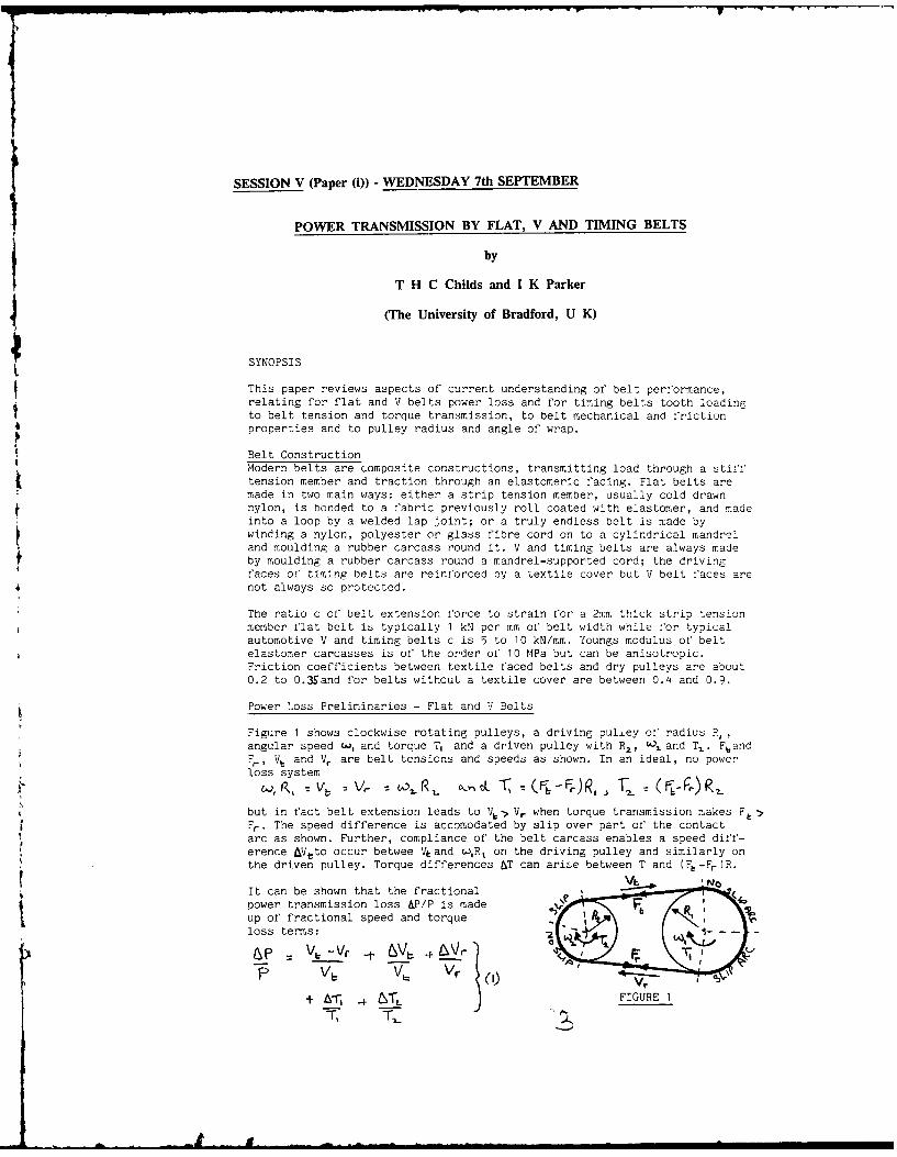
Figure 1 shows clockwise rotating pulleys, a driving puliey of radius P,,
angular speed w, and torque T, and a driven pulley with R2 , Qsand T,. FbandFr, V, and Vr are belt tensions and speeds as shown. In an ideal, no power
loss system
4but in fact belt extension leads to Vb Vr when torque transmission makes F,>
Fr. The speed difference is accomodated by slip over part of the contact
arc as shown. Further, compliance of the belt carcass enables a speed diff-erence &Vtto occur betwee V and wR, on the driving pulley and similarly on
the driven pulley. Torque differences &T can arise between T and (Fb-Fr)R.
It can be shown that the fractional
power transmission loss &P/P is madeup of fractional speed and torque
R
loss terms: -
+ Ar & _T_ FIGURE 1
Flat Belt Power Losses
Classical theory Iconsiders only losses due to extension creep, the firstterm of equation 1, and shows that
( VE - V)/v, [ -)/C(-
As (t- F,) increases, the no slip arc reduces until, by the capstan formula,when /F. = exp(pe), it disappears and then a sudden transition to skiddingoccurs. e is the angle of wrap between belt and pulley.
Subsequently it has been shown that shear of the belt carcass in the no sliparc gives rise to 4V/V loss terms. These are only significant when Re.LA<1.RBeis the length of the no slip arc and A is (G/c)(d/t). G is the carcass
shear modulus, t the carcass thickness and d the belt width. As Re8
A reducesto zero, AV/V increases steadily to infinity. With increasing torque thereis thus a steady transition from equation 2 losses to skidding.
Experiments 3show that thick flat belts can also experience speed losses dueto radial compression of the carcass. They also show torque losses, in thesame way as V belts, considered next, but not yet properly analysed.
V Belt Power Losses
Belt carcass compliance in the pulley groove of a V belt transmission
results in radial motion of the belt as its tension changes round the arc ofcontact. This can significantly increase the length of the slip arc for agiven torque and also results in soeed loss terms: for two equal pulleys
&, ,+ a /,= (F,.- PF)( a /k-~) (S)where g is the belt's radial compliance, typically 0.02 to 0.05 7'lN.
Hysteresis in V.Belt bending at entry to and exit from a pulley causestorque lossesr F,-rther torque los~es are caused ."6 di:'ferenoee i6 lidt o:the belt in the pulley groove at entry and exit: experiments~wit
' two eqCal"
radii pulleys show 0 0. 5(F+ )r ( /T (IP,
where ET is belt bending stiffness: current analyses underestimate thlz.
Carcass shear, known to be important for flat belt losses, has not yet beenconsidered in the context of V belt losses; equations 2 and 3 predict no
dependence of speed loss on angle of wrap. Experiments will be reported thatshow that speed losses increase as angle of wrap, and belt tension too,decrease. Empirical equations exist for relating the efficiency of a V be!tdrive to the pulley layout.
Power Transmission by Timing Belts
Meshing between timing belt and pulley teeth enables torque transmissionabove the capstan f'ormula limits for flat and V belts, without any speed
loss. Torque loss occurs due to sliding at entry and exit. However the mainfnterest of mechanical analysesahas been to relate tooth loading to tension
mcber and belt tooth stiffness, to pitch differences between belt andpulley teeth and to drive geometry, because tooth loading determines belt
life, either limited by tooth fatigue or by cover wear.
1. SWIFT H.W., Proc I Mech E, 1928, 2, 659-699.2. FIBBANK T.C., Int J Mech Sci, 1970, 12, 1053-1064.
3. CHILDS T.H.C. and COWBURN D., Proc I Mech E, 1987, 201 pt D, 33-53.4. GERBERT G.B., Acta Polytechnica Scandinavica, 1972, Mech Eng Series No 67
5. GERBERT G.B., Trans ASME Jnl Engng Ind, 1974, 96, 877-885.
6. NAJI M.R. and MARSHEK K.M., Trans ASME Jnl Mechanisms, 1983, 105, 339-347
.. .. .. ... . . ....-- .. . . . .. .- ,, _._
t SESSION V (Paper (ii) - WEDNESDAY 7th SEPTEMBER
POWER RATING OF FLAT BELTS - A WEAR APPROACH
by
G Gerbert
(Chalmers University of Technology, Cdteborg, Sweden)
SYNOPSIS
Modern flat belts consists of a kernel of fiber reinforced elastomericmaterial which takes up belt tension. One or both of the flat surfacesare covered with a thin layer of high friction material.
The power rating procedure of flat belt drives described inmanufactures catalogues is based on testing and experience, Itappears that the procedure might be adopted to a linear wear modelof the surface layer.
BackgroundIn most textbooks on machine elements the failure mechanism of a
flat belt is assumed to be tensile stress fatigue. The tensile stressa is a combination of belt tension and bending stresses
o = F2/ (b h) + F h / D
Application of the coefficient of traction A = (F2 - Fj) / (F2 + F)transforms tight side tension F2 to effective pull Fu = F2 / ('+A).The specific effective pull is F = Fu / b or with stresses
% = (a - E h / D) h / (1 + A)
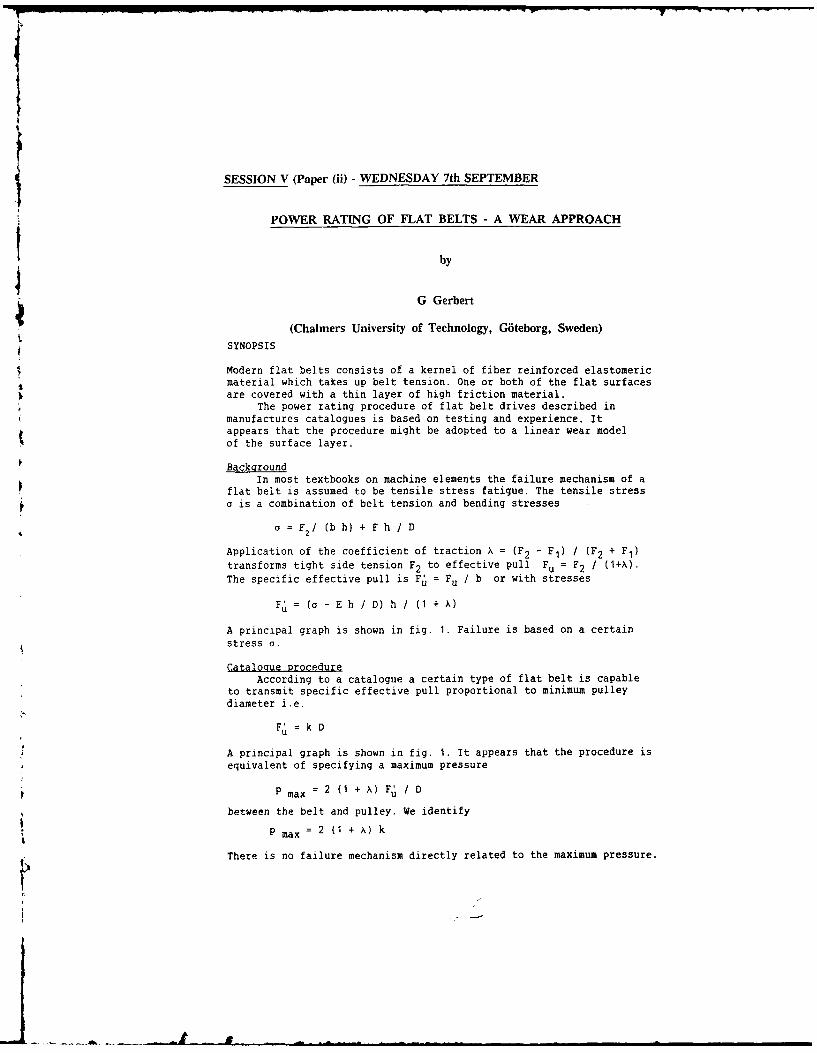
A principal graph is shown in fig. 1. Failure is based on a certainstress a.
Catalogue ProcedureAccording to a catalogue a certain type of flat belt is capable
to transmit specific effective pull proportional to minimum pulleydiameter i.e.
% = k D
*A principal graph is shown in fig. 1. It appears that the procedure isequivalent of specifying a maximum pressure
p P max = 2 (1 + A) F / D
between the belt and pulley. We identify
P max =2 (1 + A) k
There is no failure mechanism directly related to the maximum pressure.
F.
Recommended Friction Core Top
interval I - coating surface
Figure 1. Competing Figure 2. Cross sectionfailure mechanisms of flat belt
Wear concePtA cross section of a flat belt is shown in figure 2. Wear out of
the friction layer leads to malfunction and failure of the drive.The linear wear rate law reads
w = p v / W (W = wear strength)
There are mainly two factors contributing to the sliding velocity vviz. belt elongation (creep) an pulley crowning.
Belt elongationThe sliding velocity due to stretching of the belt is
v = V (F - F ) / (bc') where c' = hE = specific strain stiffness.Simple flat belt mechanics gives
p = F / (b R) ; dF = F dip
The wear during one passage of a pulley then becomes
sS = (F')2 / ( 2 p W c')
Pulley crowningThe pulley has a slight curvature in the axial direction the
hight of which is A. The sliding velocity on top of the pulley isv = V A/D. Again application of p and dF gives the wear contributionduring one passage to
s c = F A / (P W D)
It is recommended that A/D z 0.003 : const.
Total wearBy summing the two contributions we get
(F )2 / (2 c') + F A / D = P W s
Failure is based on a certain wear s. A permissible Fu can be calcu-lated which is independent of pulley diameter as shown in fig.1.
Power ratinaWear of the friction layer of a flat belt leads to a gradual
decrease of the function of the belt and that is to be preferredcompared to belt breakage. Power rating can be based on the derivedequation so the situation shown in figure i will occur.
SESSION VI (Paper (i) - WEDNESDAY 7th SEPTEMBER
THE RELATIONSHIP BETWEEN UNEVEN TOOTH CONTACT LOADING
AND SURFACE DURABILITY IN FLEXIBLE GEAR DESIGNS
by
J F Harrop and A Tam
(Pratt and Whitney, Canada)
SYNOPSIS
Aero engine gearboxes must be compact, light-weight, durable, easy to maintain and
low cost in order to meet the demands of a highly competitive gas turbine market.
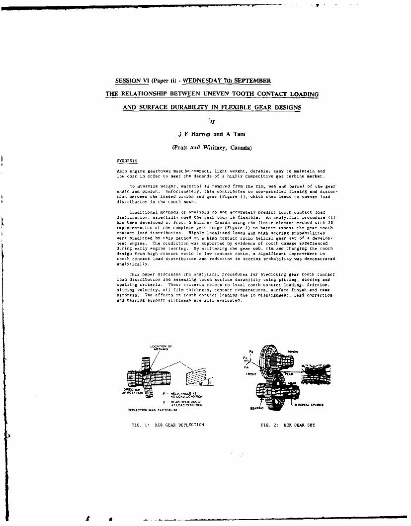
To minimize weight, material is removed from the rim, web and barrel of the gearshaft and pinion. Unfortunately, this contributes to non-parallel flexing and distor-tion between the loaded pinion and gear (Figure 1), which then leads to uneven loaddistribution in the tooth mesh.
Traditional methods of analysis do not accurately predict tooth contact loaddistribution, especially when the gear body is flexible. An analytical procedure (I)has been developed at Pratt & Whitney Canada using the finite element method with 3Drepresentation of the complete gear stage (Figure 2) to better assess the gear toothcontact load distribution. Highly localized loads and high scoring probabilitieswere predicted by this method on a high contact ratio helical gear set of a develop-ment engine. The prediction was supported by evidence of tooth damage experiencedduring early engine testing. By stiffening the gear web, rim and changing the toothdesign from high contact ratio to low contact ratio, a significant improvement intooth contact load distribution and reduction in scoring probability was demonstratedanalytically.
This paper discusses the analytical procedures for predicting gear tooth contactload distribution and assessing tooth surface durability using pitting, scoring amdspalling criteria. These criteria relate to local tooth contact loading, friction,sliding velocity, oil film thickness, contact temperatures, surface finish and casehardness. The effects on tooth contact loading due to misalignment, lead correct.osand bearing support stiffness are also evaluated.
- O HELIX A..Tk
AT LOAD CONDITION'-GEAR HELIX ANGLE
AT LOAD CONDITION OP ITEtAL SPLJKNE
DEFLECTION MAG. FACTOR B A"
FIG. 1: HCR GEAR DEFLECTION FIG. 2: HCR GEAR SET
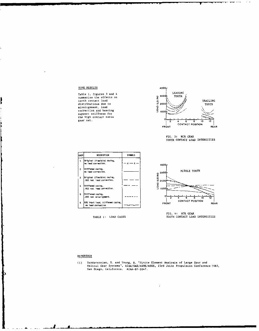
SOME RESULTS 4000r
Table 1, figures 3 and 4 LEADING
summarise the effects on z 30001 TOOTH A.
tooth contact load TRAILINGdistributions due to 2000 TOOTHmisalignment, lead C /
0 : -Joecorrection and bearing I 1000 "support stiffness for ....- *
the high contact ratiogear set. 2 4 6 8 10 12
CONTACT POSITION 1FRONT REAR
FIG. 3: NCR GEARTOOTH CONTACT LOAD INTENSITIES
CASE DESCRIPToN SYNBOLS
I original (flexible) casing,no lead correction. - x -4 -0
2 Stiffened casing, Mno lead correction. 3 00 0L MIDDLE TOOTH
z
3 original (flexible) casing, C3.002 rad. lead correction.. -00
4 Stiffened casing, -- - -
.002 rad. lead correction. -J 1000 -
5 Stiffened casing, -
.002 red. misaiigmeent. 4 6 8 10 12
6 50% Input load, stiffened casing, FRONT REARno lead correction
FIG. 4: HCR GEAR
TABLE 1: LOAD CASES TOOTH CONTACT LOAD INTENSITIES
REFERENCE
(1) Sundararajan, S. and Young, B. "Finite Element Analysis of Large Spur andHelical Gear Systems", AIAA/SAE/ASME/ASEE, 23rd Joint Propulsion Conference 1987,San Diego, California. AIAA-87-2047.

SESSION VI (Paper (ii) - WEDNESDAY 7th SEPTEMBER
TEMPERATURE - AND PRESSURE-MEASUREMENTS IN GEAR CONTACTS
WITH THIN-FILM-TRANSDUCERS
by
H Peeken and P Ayanoglu
(Institut Fuer Maschinenelemente und Maschinengestaltung,RWTH Aachen, West Germany)
SYNOPSIS
The project has the aim of investigating the temperature- andpressure distributions in the elastohydrodynamic lubricatingfilm in gear contacts, using sputtered thin-film transducers,which can be applied in various positions on the toothsurface.
Test Gear and Thin-Film Transducers
The experiments are carried out on a purpose-built gear rig.The gears are loaded by means of a belt-drive with acontinuously variable ratio.
A specially designed gear wheel with offset teeth wasnecessary to enable the coating of the tooth surface in thesputtering apparatus.
Thin-film transducers function as Ohm-resistances, whichchange under temperature and pressure infuence. They areproduced in a sputtering apparatus. The first process is thatof coating the tooth flank with an isolating alumina-film.The transducer is sputtered onto this layer, using a mask.The transducer material is manganin for pressure- andtitanium for temperature-transducers. Finally, a second,protecting layer of alumina is applied onto the transducer.
The transducers are then calibrated, to determine theirpressure- and temperature-coefficients.
Results
Experiments were carried out so far with three manganin- andone titanium transducer, all positioned above the pitch-point.
The pressure curves show typical elastohydrodynamic pressuredistributions, with a gradually increasing gradient in theinlet zone. Elliptical distribution is seen in the parallelgap, followed by an abrupt fall in the outlet region (Fig.1).
There were noticable differences between values measuredunder the same conditions, but with different teeth of theopposing gear, with peak pressures sometimes more than twiceas high as the calculated values. This can be explained withthe unequal load distribution over the tooth width, a resultof the directional errors of the tooth profiles. The peakpressure doesn't increase in the same rate as the load, as
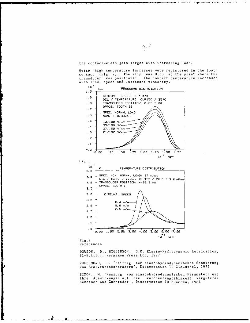
the contact-width gets larger with increasing load.
Quite high temperature increases were registered in the toothcontact (Fig. 2). The slip was 0,33 at the point where thetransducer was positioned. The contact temperature increaseswith load, speed and lubricant viscosity.
I410 ba PRESSURE DISTRIBUTION
1.0.9 CIRCUMF SPEED: 8. 4 m/s.9
OIL / TEMPERATURE: CLP150 / 25)C.8 TRANSDUCER POSITION: r=83,3 mm
OPPOS. TOOTH 36.7
SPEC. NORMAL LOAD
.5] NOM. / INTEGR.:.5 42/198 N/- _II \4 3569 N/-
.2
1
0.00 .25 .50 .75 1.00 1.25 1.50 1.75-4
10 SEC
Fig.1
10 K TEMPERATURE DISTRIBUTION5.0 -
4. SPEC. NOM. NORMAL LOAD: 37 N/,.OIL / TEMP. / VISC.: CLPI5 / 20 C / 310 mP,
4.0 TRANSDUCER POSITION: -=82.8 mm
35-OPPOS. TOOTH 1~~~~3. 5 OPS OT
3.0 CIRCUMF. SPEED
2. 52.5 8.4 lS-
2.02 5 ".1.
1.5
1.0
.5
.00. 00 1. 00 2. 00 3. 00 4. 00 5. 00 6. 00 7. 00
-410 SEC
Fig.2References
DOWSON, D., HIGGINSON, G.R. Elasto-Hydrodynamic Lubrication,SI-Edition, Pergamon Press Ltd, 1977
RODERMUND, H. 'Beitrag zur elastohydrodynamischen Schmierungvon Evolventenzahnridern', Dissertation TU Clausthal, 1975
SIMON, M. 'Messung von elastohydrodynamischen Parametern undihre Auswirkungen auf die Grubchentragfdhigkeit vergUteterScheiben und Zahnrader', Dissertation TU MUnchen, 1984
SESSION VI - (Paper (iii)) - WEDNESDAY 7th SEPTEMBER
A STATIC AND DYNAMIC ANALYSIS OF MISALIGNED GEARSWITH PARTIAL CONTACT AREAS
by
Ph Sainsot Ph Velex and D Berthe
(Institut National Des Sciences Appliquees de Lyon France)
SYNOPSIS
This paper presents an evaluation of the influence of misalignments ontooth load distribution in gear systems.
Static and dynamic analyses are conducted .ising a normal contact algorithmincluding local and global effects.
This algorithm is shown to be well adapted to determine the pressure fieldbetween surfaces with any manufacturing errors, inversely, profile modificationscan be calculated to have a given load distribution.
The dynamic problem is treated on a simplified reduction unit model, someexamples of instantaneous tooth loading, variations of conuact stiffness, andcritical rotation speeds are given.
Results show that contact conditions may strongly depend on the overallmechanical environment.
SESSION I (Paper (i) - THURSDAY 8th SEPTEMBER
THE PALMGREN-MINER RULE DERIVED
by
J J Kauziarich
(University of Virginia, U S A)
SYM2PSIS
The Pa.baren-mner linear damage rule predicts fatigue failure of theccmponent when the suation of the cycles of reversed stress amplitude, 'i,to the cycles of stress causing failure at each stress amplitzde, Ni, equalsunity, i.e., ZiN'i/N4=1. It is shown that the failure strength curve for arolling element bearing represents an ,,energy of failure."' As such it ispossible to sum the total ,energy of failure" for a variable loading dutycycle and derive the P-M Rule. It is shown that the Rule assumes the ratedfatigue life curve exponent incorrectly, but that it is possible to revise theRule to take into account the correct rated life exponent.
Theory
The AF standard load rating for bearings is a probability equation in whichthe rated load at which 90% of a group of apparently identical bearings willgive a life of at least 106 revolutions before the first evidence of failureby fatigue is detected, and is
LI( = 106 (C/P)3 (]
where C is the rated dynamic load listed in tables of standards and P is theactual load.
The maxdum orthogonal shearing stress strain energy density amplitude,WS, for a roller bearing is given by
Ws = 0.0521 P'rE* [2]GZ
where Q is the shear modulus, 3 is number of rollers, P,=P/L where P isbearing load and L is roller length, the gecmetry factor r=-l/Rl+l/R 2 , and thereduced modulus E*=E/2(l-g 2 ) where ;L is Poisson's ratio.
The most important aspect of the analysis is that the external load onthe bearing, P (P, = P/L), is directly proportional to the subsurface strainenergy density aMlitude, WS (Eq. 2), which is occurring in the raceway orrollers, so that N P -- "-E: gy of Failure." Thus, the product of N times P ona fatigue strength plot is proportional to energy, and has all of thecharacteristics of a scalar function.
paiigrer-Miner Rule
Consider a simple duty cycle applied to a roller bearing where the loadcontinually varies between P1 for N,1 e and P2 for N'2 revs, Where the=nnber of revs to failure at the respective loads is N1 and N2 , and after smunknon mmber of revs, N, a detectable fatigue failure occurs. The energy of
failure equation is
P11;' 1 + P2N' 2 = PaxP (3]
Defining ni = Ni/Ni and making use of Eq. I where Lo = N, Eq. 3becomes
n1 (P1/Pavg) 1-P + n2 ( 2/Pvg)l-P = 1 [4]
If is assumed that the value of the exponent p which comes from the equationof rated life, Eq. 1, was p=l, then Eq. 4 will become the Palmgren-Miner Rule,I ZEini=EiN' i/Ni7-1•
It is seen that the Rule makes a drastic assumption about the slope ofthe rated life equation, as well as neglecting the effect of crack growthlength during progressive fatigue crack etension.
In order to use the P-M Rule for rolling element bearing selection, wedefine ai = No i/N. Then, get
10 6 C3/1pM = Ei aiPi 3 [5]
Applications of Eq. 5 are shown iii modern machine design texts.
P-M Rule Revised
Now reconsider Eq. 4, where Eq. I shows that p=3. The unknown average load is
Pavg=--L Zi Pi aiN= i iP [6]N
Substituting Eq. 6 into 4 with p3, and using Eq. I results in a newequation for rolling element bearing selection with a known duty cycle, of
106 C3/Nrev = [IZi aiPi]3 [71
Discussion
The revised P-M Rule will predict a higher value for fatigue life of rollerand ball (with conforming races) bearings depending upon the loads and cycleratio encountered. A search of the literature did not result in any test datafor variable loaded bearings, but all of the bearing manufacturers recommendthat the P-M Rule be used when designing for variable load.
SESSION VII - (Paper (ii)) - THURSDAY 8th SEPTEMBER
PREDICTION OF ROLLING BEARING LIFE
UNDER PRACTICAL OPERATING CONDITIONS
by
E loannides, B Jacobson and J H Tripp
(SKF Engineering & research Centre B V, The Netherlands)
ABSTRACT
A previously developed fatigue life model for rollingcontacts, Ref. [i], calculates the expected life of astressed volume from the survival probabilities of thoseconstituent volume elements exposed to a stress level abovethe local fatigue limit. The application of this model isextended in the present work by exploiting its ability tohandle completely general stress distributions. Restrictionto idealized Hertzian contact stresses is no longer necessaryand a variety of realistic bearing situations can beinvestigated. This is necessary as with the advent ofimproved, cleaner, steels an increasing percentage ofbearings suffer surface initiated fatigue as compared withthe sub-surface initiated fatigue associated more withearlier "dirtier" steels. Important factors in such surfacefailures are higher surface stresses and stress concen-trations around surface features like asperities or dentscreated by particulate debris in the lubricant. Moreover,the presence of residual or internal stresses, which can beeither local around the above-mentioned surface features ormore widespread within the races of the bearings, has to beconsidered in such detailed calculations. This is veryimportant when such stresses become tensile, a status which,when combined with high shear stresses, is more likely toinitiate fatigue.
For this purpose, multi-axial fatigue criteria are introducedinto the life calculation in which the damaging effect of theshear stress is modified by the simultaneous prevailinghydrostatic pressure. Using these concepts, differentpractical aspects of the bearing operations have beenexamined and their effect on the bearing life is discussed.
Surface roughness has a large influence on the local stressesclose to the bearing surfaces and the contact stresses of theideally smooth bearing surfaces are significantly modified bythe actual topography imposed by the manufacturing finishingprocesses - grinding, honing, polishing, etc. The gap formedby the roughness is obtained directly from surfaceprofilometry, which provides a sampling of surface heightswith the usual known limitations of random signal represen-tation. Such a height sample is regarded as providing the
-1-
only available geometrical information, so that the need tointerpolate between sampled points, i.e., to introduce anasperity model, is completely avoided. Corresponding to thisstep height representation of the surface, the normal contactstress is also computed as a step distribution. From suchstresses, the sub-surface stress fields in the raceway androlling element may be found and input to life calculations.Life predictions relative to the nominal smooth contact showthe strong effect of the large stress fluctuations associatedwith regions of high slope near the more prominent surfacefeatures.
Finally, this work is being extended to study running-ineffects. Preliminary results unexpectedly suggest that arun-in surface may show a life reduction relative to theunrun profile. The conditions under which this occurs willprovide valuable information on possible extensions to thelife model, going beyond purely elastic, geometricallydetermined stress distributions.
The modification of the stress field introduced by the EHLlubricant film is also discussed.
The original calculations by Lundberg and Palmgren assumedpressure distributions between the rolling elements equal todry contact pressure distributions without friction betweenthe surfaces. By using actual calculated pressure and shearstress distributions on the bearing surfaces, it is nowpossible to see the influence of the lubricant rheology notonly on the film thickness and power loss (friction) but alsoon bearing life.
The most influential parameters for lubricants regardingstress distributions in the steel surfaces are viscosity,pressure viscosity and temperature viscosity coefficients,elasticity, compressibility, shear strength increase propor-tionality constant, and solidification pressure.
When the maximum pressure in the EHL contact is well belowthe solidification pressure for the lubricant at the localtemperature, the shear velocity has to be high to induce highshear stresses in the oil. This means that rather high slipvelocities can be accommodated in the oil without causing theshear stress to reach the shear strength of the oil. Thiscan be seen when comparing a naphthenic oil with a polyalpha-olefine oil, as a roller bearing working with a maximumcontact pressure of, say, 1 GPa will get high shear forces inthe oil film for very small slip velocities when it islubricated with the naphthenic oil, but the polyalphaolefineoil, which is still liquid at 1 GPa, will easily deform andaccommodate the slip velocity.
Next, when the effects of contamination are investigated, itis important to consider the residual stress field in theneighbourhood of debris-generated dents. In this case it isparticularly important to account for the deliterious effects
-2- ,-
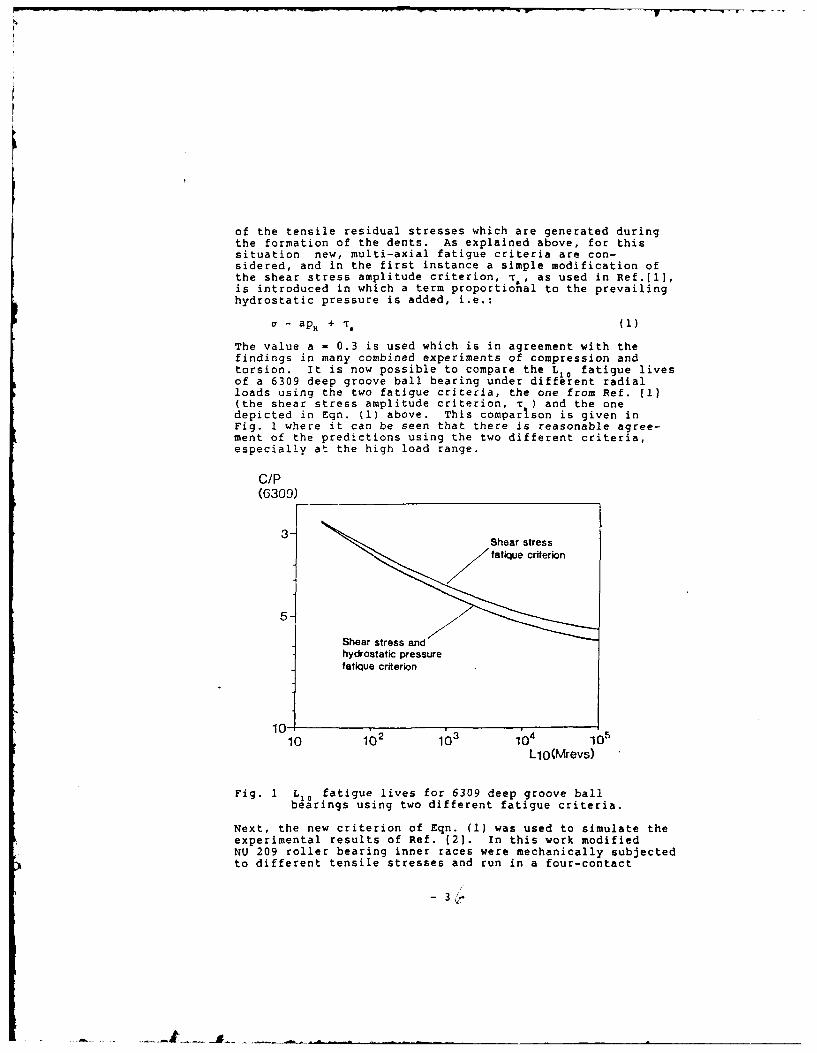
of the tensile residual stresses which are generated duringthe formation of the dents. As explained above, for thissituation new, multi-axial fatigue criteria are con-sidered, and in the first instance a simple modification ofthe shear stress amplitude criterion, T, as used in Ref.[l],is introduced in which a term proportional to the prevailinghydrostatic pressure is added, i.e.:
a - apH + T- (1)
The value a - 0.3 is used which is in agreement with thefindings in many combined experiments of compression andtorsion. It is now possible to compare the L fatigue livesof a 6309 deep groove ball bearing under different radialloads using the two fatigue criteria, the one from Ref. [I](the shear stress amplitude criterion, r ) and the onedepicted in Eqn. (1) above. This comparison is given inFig. I where it can be seen that there is reasonable agree-ment of the predictions using the two different criteria,especially at the high load range.
c/p(6309)
3- Shear stress
Sfatique crierion
Shear stress andhydrostatic pressurefatique criterion
10- 210 102 103 104 105
LiO(Mrevs)
Fig. 1 L,0 fatigue lives for 6309 deep groove ballbearings using two different fatigue criteria.
Next, the new criterion of Eqn. (1) was used to simulate theexperimental results of Ref. 12]. In this work modifiedNU 209 roller bearing inner races were mechanically subjectedto different tensile stresses and run in a four-contact
3
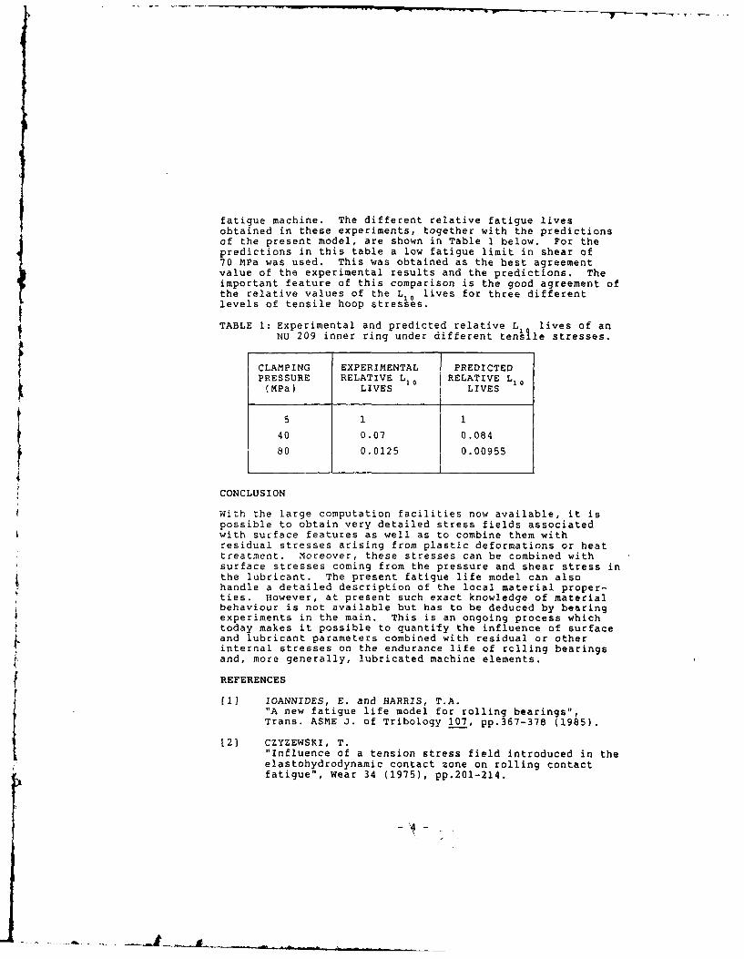
fatigue machine. The different relative fatigue livesobtained in these experiments, together with the predictionsof the present model, are shown in Table 1 below. For thepredictions in this table a low fatigue limit in shear of70 MPa was used. This was obtained as the best agreementvalue of the experimental results and the predictions. Theimportant feature of this comparison is the good agreement ofthe relative values of the L10 lives for three differentlevels of tensile hoop stresses.
TABLE 1: Experimental and predicted relative L lives of anNU 209 inner ring under different tensle stresses.
CLAMPING EXPERIMENTAL PREDICTEDPRESSURE RELATIVE L,, RELATIVE L1 ,(MPa) LIVES LIVES
5 1 1
40 0.07 0.084
80 0.0125 0.00955
4
CONCLUSION
With the large computation facilities now available, it ispossible to obtain very detailed stress fields associatedwith surface features as well as to combine them withresidual stresses arising from plastic deformations or heattreatment. Moreover, these stresses can be combined withsurface stresses coming from the pressure and shear stress inthe lubricant. The present fatigue life model can alsohandle a detailed description of the local material proper-ties. However, at present such exact knowledge of materialbehaviour is not available but has to be deduced by bearingexperiments in the main. This is an ongoing process whichtoday makes it possible to quantify the influence of surfaceand lubricant parameters combined with residual or otherinternal stresses on the endurance life of rolling bearingsand, more generally, lubricated machine elements.
REFERENCES
[I] IOANNIDES, E. and HARRIS, T.A.
"A new fatigue life model for rolling bearings",Trans. ASME J. of Tribology 107, pp.367-378 (1985).{2] CZYZEWSKI, T."Influence of a tension stress field introduced in theelastohydrodynamic contact zone on rolling contactfatigue", wear 34 (1975), pp.2 01-214.
SESSION VII -(Paper (iii)) - THURSDAY 8th SEPTEMBER
SURFACE DAMAGE OIN ROLLING ELEMNENTS AND ITS SUBSEQUENT EFFECIS ONPER FORM.NC AND LIFE
byR S Sayies tImperial College U K)E loannides (SKF The Netherlands)
.1 C flamer timperial C peU K)A A Luhirecht (Tweitte Urtivcrsitv of TcrcinoloiV t, N
and.~t.Wz'~ t~' ___
F-a ~ ~ ~ ~ ~ ~ not~,", - ..- _________ o;LSLL.
navif, tod -- t~ ih state (-F stre ir, a bearir. raeewav~l -Joe eras ....e
12 7 c l i ',7 u tio 12C tatt-o -Lte-i;ni~h h , r o~fe.t
TQ ot'taos a znrro-t 7etuet - Ax.rwc:iec " j~L.;..5 0.
'32 S'f t" of)~ " t; 1[. d
MIHll _ "12 t zul Coult e d e am'W l epc to theC Her-tz, nn3ct si7z
1, - -ot, ctu:c~ was caicuisraed to:r a cene or pos~t:ons du&L- h e-e-l%
dc caedefect. This prce suuL';Led by. a di-rt rrethcd (Nc-xton RapTas1cn',reu'c
me st. zonnputng foi for lar~p problemts. To solve the dvcontact -e7rcblein ;ihmoet
itert~ve tiFot irctttcd wa> used A,1:11tt a-p~aro , j;n;;thCijeS to- tIC Cf~ro
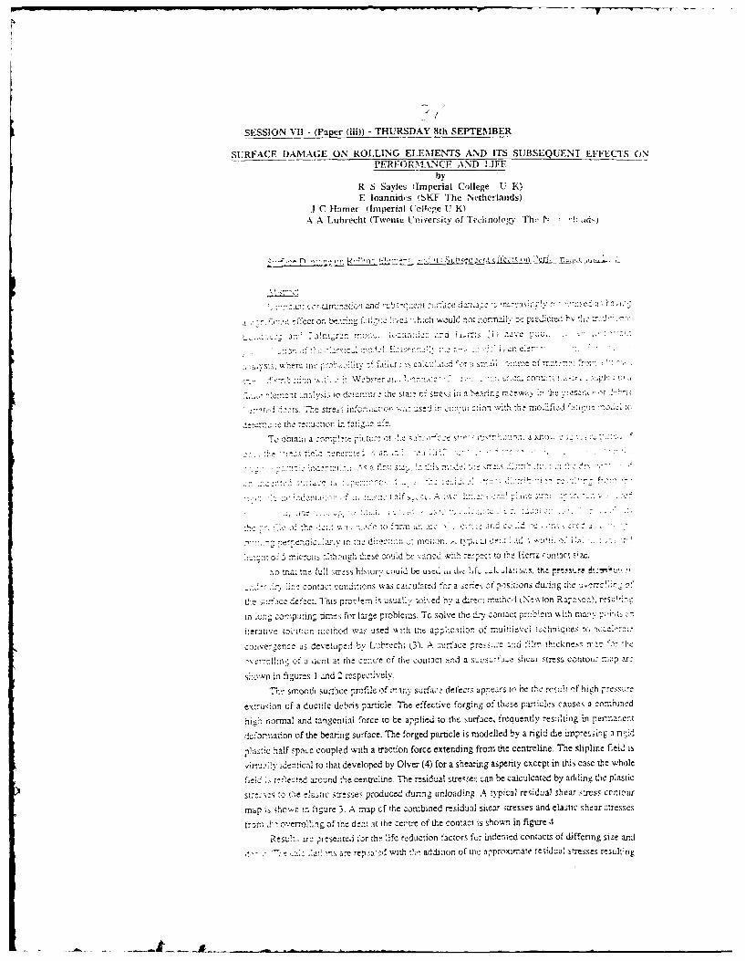
coegnaus developed by Lbch 3.A ;urfacc rssc a: d flt th-cnese -ranfr '0, 1
Qrrcl "c:C a ,'lnt at the cenue' of the contact and a su bu.ta-c shear Stress contou; :LL1 2arc
s-on in ftguro2s I and 2 r~iciev
7rhe smoothd Sul-face profile Of rnarny surfa, e defects appcecrs, to be L'%- rvscit nif high rrea"~z
ex~iuimon of a ductile debris pasticle. The effective forging of these particles causes a conninrtd
hihnormal and tangential force to be applied to th urface, frequently resi;!Tig in peznarert
drh3,ration of The bearing surface. The forged particle is modelled by a rigid die imnprcsirK a nid
paichalf space coupled with a traction force extending from the centrtline. The slipline field is
iitt!vdentical to that developed by Olver (4) for a shearing asperity except in this ease the whale
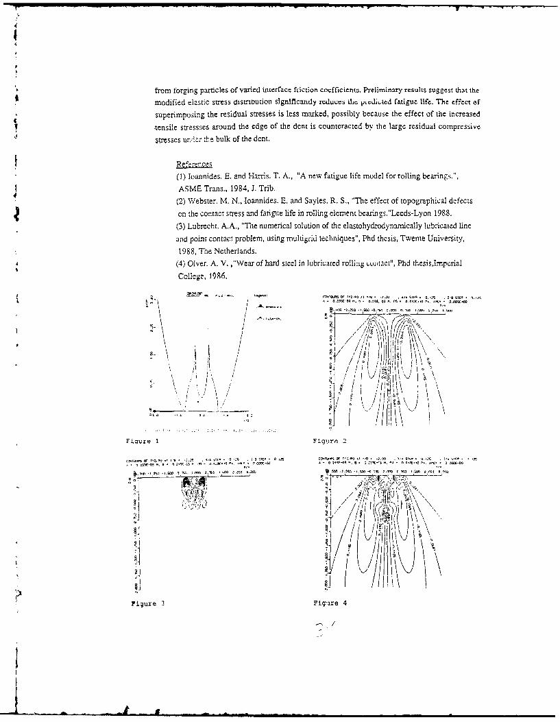
refi ectd around the centreline. *The residual stresce,: can be calculcated4 by adding the plastic
"DC~e te t! astic sttesstis produced durin~ unloading. A typical residual shear st~ss cotour
mnap i shown 1:, 'fgu~e 3. A mnap cf the comibined residual shear itresses and elastic %,hear :;tresscs
itrm f oveerol:ng of the deicot at the zcerte of the contact is shown in figure 4
Ree!.aeprt-ented ior thr! life rduction factors for indented contacts of differing size and
1 ' a-C repea-.-d with the- addition, of vie ipproximate residual stresses re!sulting
4
from forging particles of varied interface friction coefficients. Preliminary results suggest that the
modified elastic stress dtistroution stgntflcandy rcdu,;e, dic jnudi.ted tigu life. The effect of
superimposing the residual stresses is less marked, possibly because the effect of the increased
-tensile stressses around the edge of the dent is counteracted by the large residual compressive
stresses un'der 'he bulk of the dent.
(1) Ioannides. E. and Haris. T. A., "A new fatigue life model for rolling bearings.",
ASME Trans., 1984, J. Trib.
(2) Webster. M. N., loannides. E. and Sayles. R. S., "The effect of topographical defects
on the contact stress and fatigue life in rolling element bearings."Leeds-Lyon 1988.
(3) Lubrecht. A.A., "The numerical solution of the elastohydrodynamrically lub'icated line
and point contact problem, using multigrid techniques", Phd thcsis, Twente University,
1988, The Netherlands.
4 (4) Olver. A. V. ,"Wear of bard steel in lubricated rolling t.utact", Phd thesisLmperial
College, 1986.
IIV
;'u/ six-) o-- Is 2 000.0
. u - n. o.-3
.X4 / J V ,
,/ ".. ij+ I I l"
Figure 1 Fig,!re 2
1,5 .t +- 35cro ~ ab I .. *2j5 ,/ t0.A. 7.7
1 /
Figure 3 Fig ire 4
-I
SESSION VII - (Paper (iv)) - THURSDAY 8th SEPTEMBER
DEBRIS DENTING - THE ASSOCIATED RESIDUAL STRESSESAND THEIR EFFECT ON THE FATIGUE LIFE OF ROLLING
BEARINGS: AN FEM ANALYSIS
by
C N Ko and E loannides
(SKF Engineering & Research Centre B V, The Netherlands)
ABSTRACT
During overrolling of debris in lubricated contacts, plasticflow takes place both in the debris particles and theraceways and rolling elements of the bearings. The outcomeof this overrolling ( a dent combined with a local residualstress field surrounding the dent. Elastic-plasticcalculations were performed for typical bearing-debrisconfigurations using the FEM program ABAQUS, and suchresidual stress fields, as well as the resulting dent shapes,were obtained. These have been subsequently used to predictthe fatigue life reduction of rolling bearings in the waydescribed in Ref.(l].
This follows on from the work reported recently in Ref.[2]and the effects of strain rate hardening, debris and rollingbearing component hardness on the fatigue life of bearingsare discussed and assessed.
REFERENCES
[1] HAMER, J.C., SAYLES, R.S. and IDANNIDES, E."Deformation mechanism and stresses created by 3rd body debris contact andtheir effect on rolling bearing fatigue fatigue"14th Leeds-Lyon Symposium on Tribology, INSA, Lyon, France, September 1987.
[21 WEBSTER, M.M., IOANNIDES, E. and SAYLES, R.S."The effect of topographical effects on the contact stress and fatigue life
in rolling element bearings",12th Leeds-Lyon Symposium on Tribology, INSA, Lyon, France, September 1985.
[31 HAMER, J.C., SAYLES, RS. and IDANNIDES, Z."Particle deformation and counterface damage when relatively soft particlesare squashed between hard anvils"(to appear on the Journal of Tribology, ASME)
SESSION VIII (Paper (i) - THURSDAY 8th SEPTEMBER
AXIALLY PROFILED CIRCULAR BEARINGS AND THEIR POTENTIAL APPLICATION
IN HIGH SPEED LUBRICATION
by
D T Gethin
(D T Gethin, University College of Swansea, U K)
Summary
The isothermal and thermal characteristics of an axially profiled circular
bore bearing are determined using the finite element technique. These are compared
with the predicted performance characteristic of a cylindrical bearing operating
over the same range of conditions. The results obtained lead to the conclusion
that the present analysis may be used to obtain general design data for an axially
profiled bore bearing operating at high sliding speed. Axial profiling reduces the
bulk operating film temperature by a small amount and it decreases the load
carrying ability of the film and frictional iosses also.
if
... ..Lr -.. .. i tumli ul li~llilll i Jil I l
P=O (a) Bearing Nomenclature
(b) Unwrapped Film P=E~ 0
T=Iin
X a~p o0 aTLza z 8a Z
Cylindrical Profile 1 Profile 2 Profile 3
(c) Admissable Profiles
FIGURE 1. BEARING NOMENCLATURE AND AXIAL PROFILES CONSIDERED.
SESSION VIII (Paper (ii) - THURSDAY 8th SEPTEMBER
ANALYSIS OF PARTIAL ARC JOURNAL BEARINGS
by
E W Cowking
(GEC Engineering Research Centre, Leicester, U K)
SYNOPSIS
This paper is concerned with the validation of computer programs for
the thermohydrodynamic analysis of journal bearings. The aim is todemonstrate the correctness of the programs mainly by external checks
on the results rather than by checking the computer code.
The Computer Programs
Two computer programs are considered which analyse journal bearings
with a variable number of partial arcs. A range of temperaturecalculations is provided from isothermal up to full thermohydrodynamic
solutions. The inlet pockets are treated as lumped systems, each at asingle temperature which is determined by a heat balance. The two
programs produce two and three-dimensional solutions to the problem.The pressures are calculated by an optimum variational method in the
two-dimensional program and by relaxation methods in thethree-dimensional program. The two dimensional program is described in(1).
Validation Procedure
Results are compared with isothermal solutions published by Lund and
Thomsen (2) which provide accurate dynamic coefficients, obtained by
direct differentiation of Reynolds equation.
The programs include a simple thermal analysis which predicts the
average temperature across the fluid film. Results obtained by this
method for a single arc are compared with those published by Hakansson(3) in tabular form.
The thermohydrodynamic analysis of the fluid film cannot so
easily be compared with published results. It is shown, however, thatif the journal position is fixed the average temperature across thefilm agrees closely with the average temperature predicted by thesimple thermal analysis. Overall mass flow and heat flow balances also
provide useful checks on the validity (and accuracy) of results.
Thermohydrodynamic Results
There is clearly a need for results which can be used as benchmarks
for thermohydrodynamic analyses. As an attempt to improve thissituation, a table of results are provided for a 160* arc. An
adiabatic analysis is carried out for a specified lubricant andoperating conditions and for a range of loads.
References
1) Cowking, E.W.'Thermohydrodynamic analysis of multi-arc journal bearings.'
Tribology International, August 1981, p 217.
2) Lund, J.W. and Thomsen, K.K.
-A calculation method for the dynamic coefficients of oil
lubricated journal bearings.'
Topics in Fluid Film Bearing and Rotor Bearing System Design and
Optimisation, ASME, 1978, pp 1-28.
3) Hakansson, B.'The journal bearing considering variable viscosity.'
Transactions of Chalmers University of Technology, Nr 298, 1965.
s/
SESSION VIII - (Paper (iii)) - THURSDAY 8th SEPTEMBER
ELAPSED TIME FOR THE DECAY OF THERMAL TRANSIENTSIN FLUID FILM BEARING ASSEMBLES
by
C M M Ettles (Rensselaer Polytechnic Institute New York U S A)H Heshmat (Mechanical Technology Incorporated New York U S A)R Brockwell (National Research Council Canada)
SYNOPSIS
When the operating conditions of a fluid film bearing are changed afinite time must elapse before thermal equilibrium becomes re-established.This paper concerns two aspects of the thermal response of a bearing: thetime required for some proportion of the temperature change (e.g., 507.,70, 907.) and the effect of thermoelastic deformation. An attempt is madeto correlate the results of six thrust bearings and two journal bearings,to give a unified method that characterises response time.
A Simplified Approach Using Classical Solutions
When applying the equation of transient heat conduction to a plate,journal or bush, a single parameter appears when the equation is set innondimensional form. This is nondimensional time, known as the Fouriernumber F, given by
k pc _2 (1)
where k, p, c are the thermal properties, t is time and H is the thicknessof the plate or radius of the journal.
The classical solutions could be characterized by a Fourier number inthe form
AT 1 -aF (2)ATF
where AT is the time varying temperature, ATF is the final temperature
change and a is a constant of the order 1.5- 5.
A Numerical Solution of the Complete Assembly
The use of classical solutions allows a simplified, general approach,but difficulties arise in choosing the dominant thermal mass. A numericalsolution is described that considers the coupled system of pads, rotor,and film in elevation, as in li]. The complete temperature distributionis obtained in a series of time intervals, consequent to some change suchas an increase of speed or load.
Figure 1 shows the subsequent temperature rise of a thrust bearingin which the load is doubled at zero time. After the initial rise, thegrowth (or decay) is approximately exponential. In (1J it is shown thatthe behavior of a unit eight times the size was similar, which led to theuse of Eq.(2) to characterize experimental results as well as modelsolutions.

Correlation of Experimental Data
Figure 2 shows the 507. rise time for six thrust bearing units,plottid against pad thickness H. The line has the characteristict C H , which gives for these bearings:
1T I -e1 6 F (3)
ATF
One feature of Eqs.(2), (3) is that individual bearing assembliesshould have a characteristic "time constant," so that the same time elapsesfor (say) a 50% change, regardless of the final temperature change beinglarge or small. This is a common feature of experimental results.
Sec) O0. 1 0 tO0 200
1 iO00.
Thrust seoring ASemblies
002 -70o. }o .r-""
0 .0
7 001 0.01 01 I 0 1 t0 100 000
Fourier Number (-L-1 t Pad ThiChn., M imnr
Fig.l Changes in Temperature in a Thrust Fig.2 The 50% Rise Time for SixBearing when the Load is Doubled Thrust Bearing Unitsat Zero Time Subject to a Sudden Change
of Conditions
Reference
1. Ettles, C.M.M., "Transient Thermoelastic Effects in Fluid FilmBearings," Wear, 79, 53-71 (1982).
/.
SESSION VIII (Paper (iv) - THURSDAY 8th SEPTEMBER
DESIGN PROCEDURES IN HYDRODYNAMIC LUBRICATION
BASED ON NUMERICAL METHODS
by
J 0 Medwell
(University College of Swansea U K)
This paper presents a review of numerical schemes for analysing the
thermohydrodynamic behaviour of journal bearings. The schemes are based on the
finite element and finite difference methods which are used to solve the momentum
and energy equations simultaneously. Off bearing design operation such as
lubricant starvation and misalignment are featured in the procedures. The effect
of bush conduction and the recirculation of heat therein is included and the
effect of various types of boundary conditions considered.
Some comparisons with experimental data are also presented
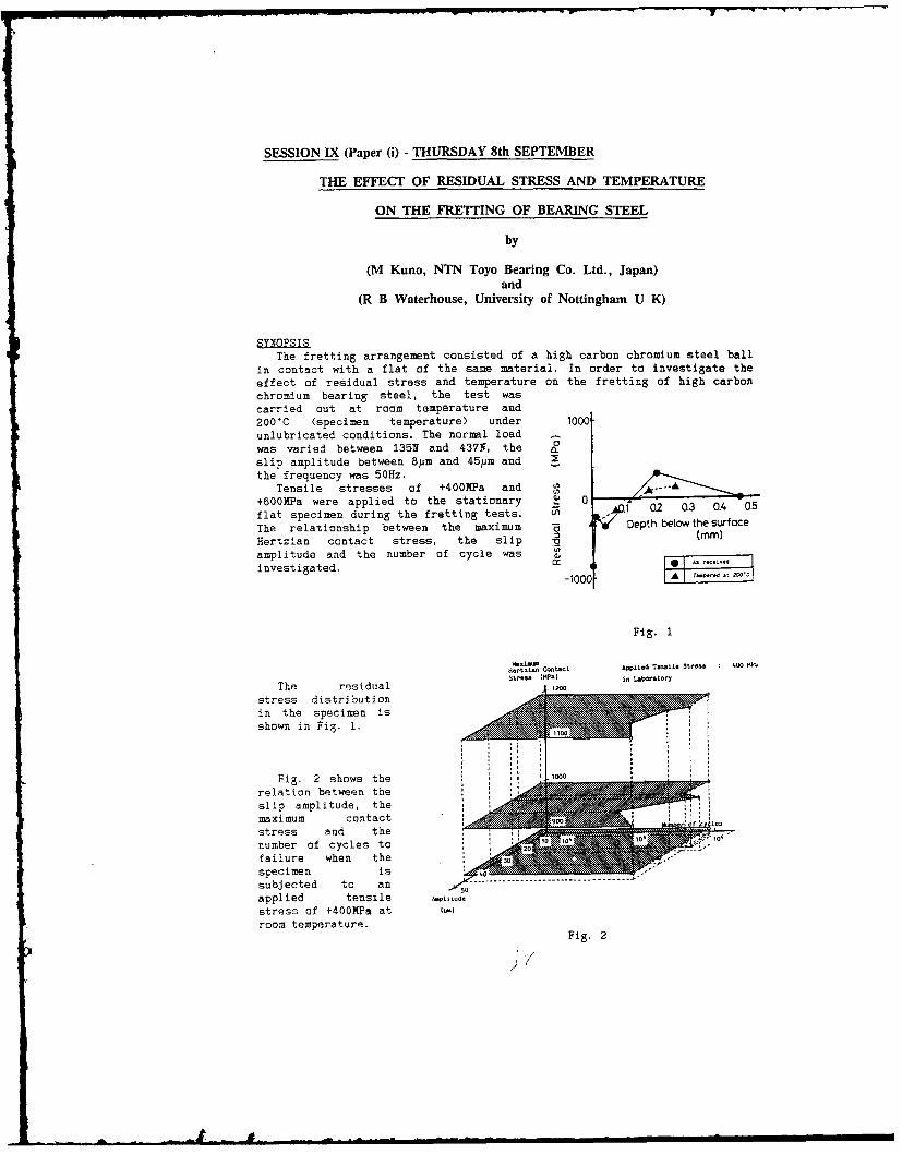
SESSION IX (Paper (i) - THURSDAY 8th SEPTEMBER
THE EFFECT OF RESIDUAL STRESS AND TEMPERATURE
ON THE FRETTING OF BEARING STEEL
by
(M Kuno, NTN Toyo Bearing Co. Ltd., Japan)and
(R B Waterhouse, University of Nottingham U K)
SYNOPSISThe fretting arrangement consisted of a high carbon chromium steel ball
in contact with a flat of the same material. In order to investigate theeffect of residual stress and temperature on the fretting of high carbonchromium bearing steel, the test wascarried out at room temperature and200"C (specimen temperature) under 1000unlubricated conditions. The normal loadwas varied between 135N and 437N, theslip amplitude between Bym and 45ym andthe frequency was 50Hz.
Tensile stresses of +400MPa and '.~
+600MPa were applied to the stationary a 0
flat specimen during the fretting tests. g o.1 02 0.3 04 0.5
The relationship between the maximum - Depth below the surface
Hertzian contact stress, the slip :3 (mm)
amplitude and the number of cycle was a
investigated.-10001 A
Fig. 1
Ijertzien Contact Applied Tenalle Stress 40 0
st-e. We)a in Law<}rtory
The residual ,20
stress distributionin the specimen isshown in Fig. 1.
Fig. 2 shows the 1000
relation between theslip amplitude, themaximum contactstress and thenumber of cycles to 10 20
failure when the 30
specimen is 4.0
subjected to an - ------------------------------------
applied tensile Nl Le
stress of 1400MPa atroom temperature.
Fig. 2
I .'
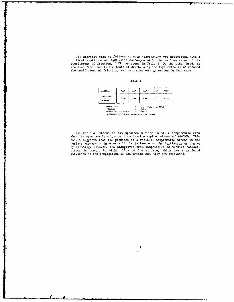
The shortest time to failure at room temperature was associated with acritical amplitude of 35pm which corresponded to the maximum value of thecoefficient of friction, 0.72, as shown in Table 1. On the other hand, nosnecimen fractured in the tests at 200"C. A "glaze type oxide film' reducedthe coefficient of friction, and no cracks were generated in this case.
Table I
A.plitude l0a 2Otm 25u- 35m 45u
Coefficientof~ii 0.50 0.-4 0.49 0.72 0.49
nocai load 437N (Pmx = 1200MPa-e cency 50Hz
aplied taneile stress 40OMPacoefficient of frict.on measured at 10' cjoles
The residual stress in the specimen surface is still compressive evenwhen the specimen is subjected to a tensile applied stress of +60OMPa. Thisresult suggests that the presence of a residual compressive stress in thesurface appears to have very little influence on the initiation of cracksby f-stting. However, the changeover from compressive to tensile residualstress is bought to within 10m of the surface, which has a profoundJmfluence or the propagation of the cracks once they are initiated.

SESSION IX (Paper (ii) - THURSDAY 8th SEPTEMBER
WEAR MAPS AND THEIR USE IN DESIGN
by
T S Eyre
(Brunel University, U K)
The transfer of technology from tribology research to designers is very slow,
particularly in wear of materials and there appears to be as many industrial
problems seeking solutions today as there were twenty years ago. In recent
years there has been considerable attention focussed upon wear testing
particularly using the pin on disc machine to measure absolute wear rates and
compare interlaboratory repeatability etc. This type of information
particularly based on single load/speed tests does not, however, help the
designer in his search for optimisation of the material variables or in the
search for new materials or surface technology for wear resistance in
engineering systems.
In this investigation a pin on disc machine is used, with some modifications,
in particular to vary the operating conditions over a wide range of load,
speed and environmental conditions. Well known engineering metals and
alloys, particularly cast iron, steel and aluminium alloys have been
characterised in terms of their composition and microstructure and then their
sliding wear resistance have been determined. A wide variety of techniques
have been used to measure or assess wear and also to characterise the main
features of the surfaces and wear debris. Wear information is expressed in
the form of running-in, steady state wear rates and also transitional
behaviour, which has then been compiled into wear maps. These wear maps not
only show how optimisation of the metal or alloy itself brings about
significant improvements in wear behaviour but also for specific materials how
wear changes with both load and sliding speed. The main emphasis is on safe
regions of wear and their boundaries relative to operating conditions rather
than single figure wear rates or wear factors. These maps are based upon
known wear types and how transitions from one form of wear i.e. "mild" to
another "severe" may cause catastrophic wear behaviour.
Intelligent interpretation of wear behaviour over a wide range of conditions
based upon a "standard" wear test, will enable designers to choose their
materials for construction with greater efficiency and with care in simulation
in the wear tests of service behaviour this information can be related to
specific industrial problem areas. Specific classes of materials can be
optimised on the basis of their known and measured characteristics i.e.
microstructure and wear.
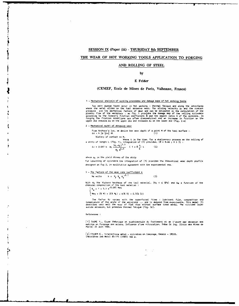
III . !I l - 7• .-- -- a
(
SESSION IX (Paper (iii) - THURSDAY 8th SEPTEMBER
THE WEAR OF HOT WORKING TOOLS APPLICATION TO FORGING
AND ROLLING OF STEEL
by
J E Felder
(CEMEF, Ecole de Mines de Paris, Valbonne, France)
1 - Mechanical analysis of working processes and damage maps of hot working tools
Two main damage types occur in hot working : thermal fatigue and along the interfaceswhere the metal slides on the tool abrasive wear. The sliding velocity 6u and the contactpressure are the mechanical factors of wear and can be estimated by the calculation of theplastic flow of the workpiece : so fig. 1 provides the damage map of the rolling cylindersaccording to the Tresca's friction coefficient ; and the aspect ratio A of the workzone. Inforging the friction conditions are often dissymetrical and an increase in friction on theupper die reduces Au on the upper die and inreases &u on the lower die (fig. 2.a)
2 - Mechanical model of abrasive wear
From Archard's law, we derive the wear depth of a point H of the tool surface4 zc = k fp IAul dt (1)
History of contact in H.I Where t is the time. for a stationnary process as the rolling of
a strip of length L (fig. 1), integration of (1) provides, (5 4 0.66 ; A > 3)
Az - 0.057 k OO (HI-H2)1"5 1 5 A) L (2)
where ao is the yield stress of the strip
For upsetting of cylinders the integration of (1) provides the theoretical wear depth profile
designed on fig 2, in qualitative agreement with the experimental one.
3 - The factors of the wear rate coefficient k
We write k = KF \W HV % (3)
With HV the Vickers hardness of the tool material. (Hv < 6 GPa) and KW a function of thechemical composition of the tool material
K v 1 + 5.1 e- 0
.0 8 5
Weq
Weq W (W) - 2(- It) .4(% V) + 0.5(% Cr)
The factor KF varies with the superficial films : lubricant film, composition and
temperature of the scale of the workpiece ... and is deduced from experiments, This model (3)
describes very well the wear of flat dies without surface treat ments. The nitrided layer
avoids abrasion, but promotes thermal fatigue (fig. 2c).
References
f1] THORE Y., Etude thdorique et expdrimentale du frottement et de l'usure par abrasion desmatrice en forgeage des aciers. Influence d'une nitruration. These Dr Ing. (Ecole des Mines de
Paris) 25 Juin 1984.
[21 FELDER E., Interactions mtal - cylindres en laminage, Cessid - IRSID.(Miziires lea Metz) 85-171 (1985) 166 p.
p . -I ii i i i i i i
SESSION IX (Paper (iv) - THURSDAY 8th SEPTEMBER
DEBRIS INCLUSION IN POLYMERIC BALL VALVE SEALS
by
B J Briscoe and P J Tweedale
(Imperial College, London, U K)
SYNOPSIS
This paper describes the results of an experimental study and an associated analysis of theparticle debris inclusion processes which occur in certain polymer-metal contacts. The workhas been designed as a means of evaluating certain facets of the operation of ball valves, whichcontain polymeric seals, when they are used in environments which contain small hard solidparticles. The particles are progressively included onto the polymer surface and as a result thetorque required to activate the valve increases. A simulation of this process is described anddata are given for a range of organic polymers. These data are analysed using a simple butapparently effective model which introduces a debris inclusion rate parameter. This parameterexpresses the sensitivity of the polymer to debris inclusion.
The data are briefly compared with field test results and the important materialcharacteristics which influence the debris inclusion rate are discussed.
Anoaratus
The apparatus to be described induces debris inclusion by a rolling action where a steel roller istraversed over a small polymeric sample. Periodically the roller is locked and the frictionalforce is measured. These studies have used a range of debris laden media but the work to bereported deals with aqueous silica suspensions. The polymers investigated include PTFE,PEEK, polyethersulphone, and a number of special composites. The latter materials will bedescribed in detail in the full paper.
Experimental Data and Analyses
Typically we observe that the frictional force required to slide the contact between the polymerand the steel progressively increases as more debris is introduced into the contact. Most of thesystems have a common limiting friction value corresponding to a fully silica encrustedsurface. The initial frictions are different; PTFE is low and PEEK is high. What is moreinteresting, however, is the rate at which the frictional force changes as the debris inclusioncycles are increased. For PTFE this is rapid whilst for PEEK it is comparatively slow undersimilar operating conditions.
The analysis to be described assumes that a certain fixed fraction of the surface isimpregnated with particles during each rolling traverse for each polymeric system. The datawhen analysed on this basis produce a parameter which describes the relative sensitivity of thepolymers to debris inclusion. PTFE for example incorporates debris quite rapidly whilstPEEK does so much more slowly.
The inclusion sensitive is an inverse function of the polymer's hardness.
Conclusions
We demonstrate that a simple simulation and analysis is capable of predicting some of theoperational features of polymeric contacts in ball valves. An important material characteristic isthe hardness of the polymer.
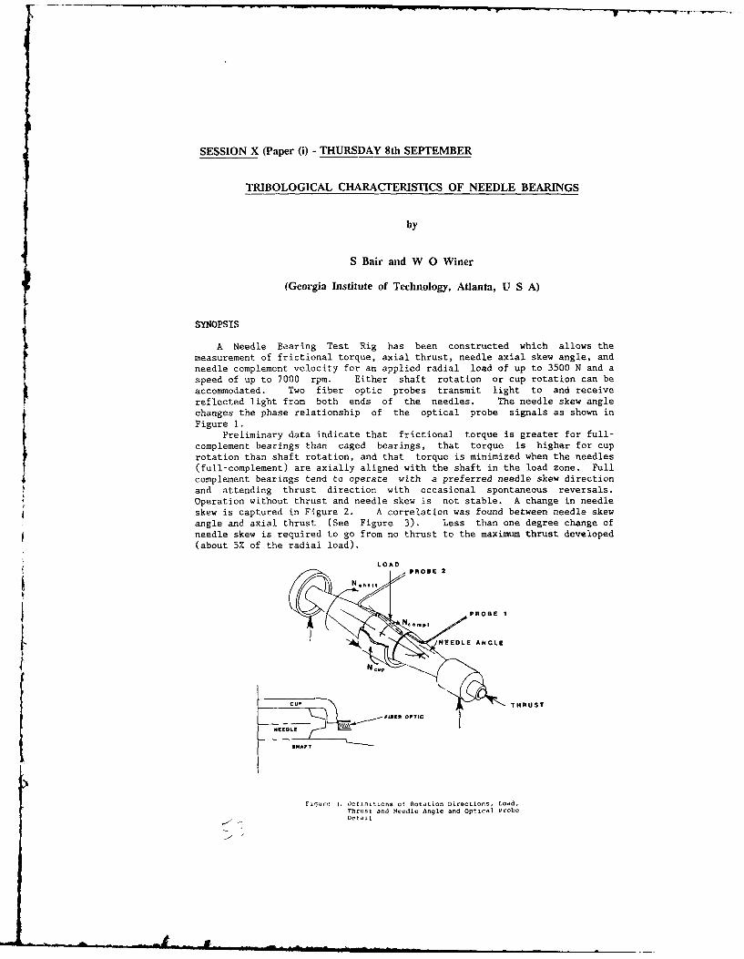
SESSION X (Paper (i) - THURSDAY 8th SEPTEMBER
TRIBOLOGICAL CHARACTERISTICS OF NEEDLE BEARINGS
by
S Bair and W 0 Winer
(Georgia Institute of Technology, Atlanta, U S A)
A Needle Bearing Test Rig has been constructed which allows the
measurement of frictional torque, axial thrust, needle axial skew angle, and
needle complement velocity for an applied radial load of up to 3500 N and a
speed of up to 7000 rpm. Either shaft rotation or cup rotation can be
accommodated. Two fiber optic probes transmit light to and receive
reflected light from both ends of the needles. The needle skew angle
changes the phase relationship of the optical probe signals as shown in
Figure 1.Preliminary data indicate that frictional torque is greater for full-
complement bearings than caged bearings, that torque is higher for cup
rotation than shaft rotation, and that torque is minimized when the needles
(full-complement) are axially aligned with the shaft in the load zone. Full
complement bearings tend to operate with a preferred needle skew direction
and attending thrust direction with occasional spontaneous reversals.Operation without thrust and needle skew is not stable. A change in needle
skew is captured in Figure 2. A correlation was found between needle skew
angle and axial thrust (See Figure 3). Less than one degree change of
needle skew is required to go from no thrust to the maximum thrust developed
(about 5% of the radial load).
LOADPROB
t~ I
- -FSROPTIC
PetaOB I
Lcup
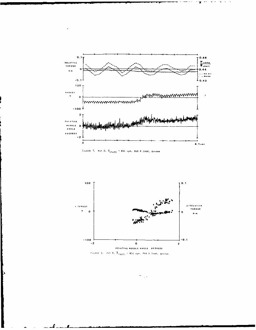
0.1-0.46
RELATIVEN
0.42
S4. 42
10 TT.
-10000.
-22
RELATIVE NEEOLE AN7E11RE
NEEDLEo 30NV ~ =80r~, h Pla,3V
. ...II U I - .;
SESSION X - (Paper (ii)) - THURSDAY 8th SEPTEMBER 1988
POWER LOSS PREDICTION IN BALL BEARINGS
by
R J Chittenden, D Dowson and C M Taylor
(The University of Leeds U K)
SYNOPSIS
A deep groove ball bearing subject to a principal load in the axial direction andoperating towards its maximum allowable rotational speed presents a complex problem for a fulllubrication analysis. The dynamic analysis of such bearings has been studied by several workers,(Gentle and Boness (I) and Pasdari and Gentle (2)) but such theoretical work required the use ofseveral experimentally derived relationships.
The work described in this paper brings together results from a bearing dynamicsanalysis and computed elastohydrodynamic film and pressure profiles. In this way a purelytheoretical model is built up which allows reasonable estimates of power loss to be calculatedfor single conjunctions as well as whole bearings. This approach requires several broadassumptions to be made since the computation of a complete elastohydrodynamic solution for eachcontact within a bearing is impractical due to the amount of c.p.u. time required. The analysisallows a representation of Non-Newtonian effects to be introduced into the analysis.
Analysis
The bearing dynamics analysis followed was that of a high speed ball bearing presentedby Jones (3.4). as set out by Harris (5). This analysis provided information on the operatingconditions at each contact within the bearing and was used together with a previously computedelastohydrodynamic solution to enable extrapolated film thickness and pressure profiles to bedetermined for each conjunction. The extrapolations were made in the following ways:-
Pressure
. .P..Pi.j P Wll i.j
'Ball
Film Thickness
Ij q .j +CHi +C3
Once these profiles had been determined local values of the shear stresses acting uponthe two surfaces were calculated according to Newtonian theory. The assumption that theextrapolated profiles would not be significantly altered by a Non-Newtonian fluid allowed afurther set of local shear stresses to be evaluated according to a Non-Newtonian stress-strainrelationship, which for the work described in this paper was that presented by Johnson andTevaarwerk (6):-
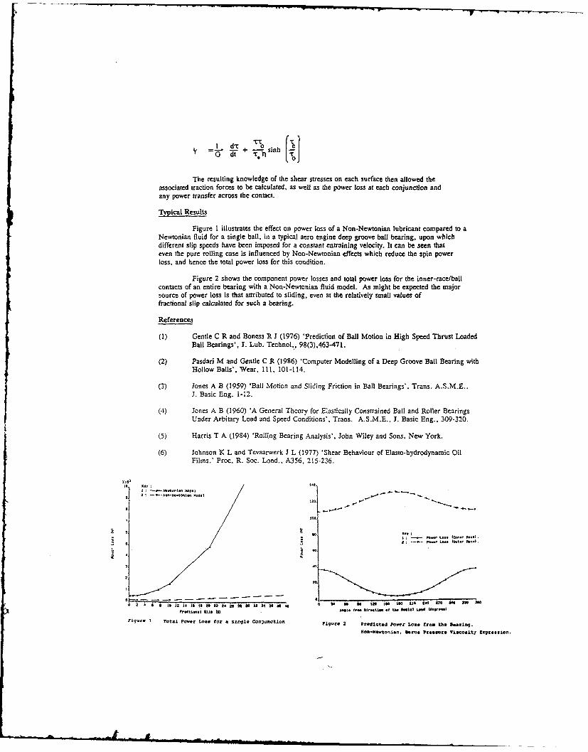
Sd'" + nih
S G dt rl
The resulting knowledge of the shear stresses on each surface then allowed theassociated traction forces to be calculated, as well as the power loss at each conjunction andany power transfer across the contact.
Typical Results
Figure 1 illustrates the effect on power loss of a Non-Newtonian lubricant compared to aNewtonian fluid for a single ball, in a typical acro engine deep groove ball bearing, upon whichdifferent slip speeds have been imposed for a constant entraining velocity. It can be seen thateven the pure rolling case is influenced by Non-Newtonian effects which reduce the spin powerloss, and hence the total power loss for this condition.
Figure 2 shows the component power losses and total power loss for the inner-race/ballcontacts of an entire bearing with a Non-Newtonian fluid model. As might be expected the majorsource of power loss is that attributed to sliding, even at the relatively small values offractional slip calculated for such a bearing.
References
(1) Gentle C R and Boness R J (1976) 'Prediction of Ball Motion in High Speed Thrust LoadedBall Bearings', J. Lub. Technol.., 98(3),463-471.
(2) Pasdari M and Gentle C R (1986) 'Computer Modelling of a Deep Groove Ball Bearing withHollow Balls', Wear, 11, 101-114.
(3) Jones A B (1959) 'Ball Motion and Sliding Friction in Ball Bearings', Trans. A.S.M.E..3. Basic Eng. 1-12.
(4) Jones A B (1960) 'A General Theory for Elastically Constrained Ball and Roller BearingsUnder Arbitary Load and Speed Conditions', Trans. A.S.M.E., J. Basic Eng., 309-320.
(5) Harris T A (1984) 'Rolling Bearing Analysis', John Wiley and Sons, New York.
(6) Johnson K L and Tevaarwerk J L (1977) 'Shear Behaviour of Elasto-hydrodynamic OilFilms.' Proc. R. Soc. Lond., A356, 215-236.
0,040
oto 3it ; |30.. .,..a ,
S: s-1-. 120-H4ti 00l .l| 0
P- 20 ..0 (O'
0 10 0
' 12 4 I S I 20 22 24 25 21 30 32 34 30 30 10 0, so Be So Soo 00 anI a00 t*
F,.ti ls I t) '01I. 1- 01-lt.l 0.i PS1. a L..grd Se... Il
Figqure I Total Power Loa. for a Single conjunctton Figure 2 Predicted Powter Loas f rom the Beairing.
lon-tewotonian, nexus Presslure Viscosity EpressOn.
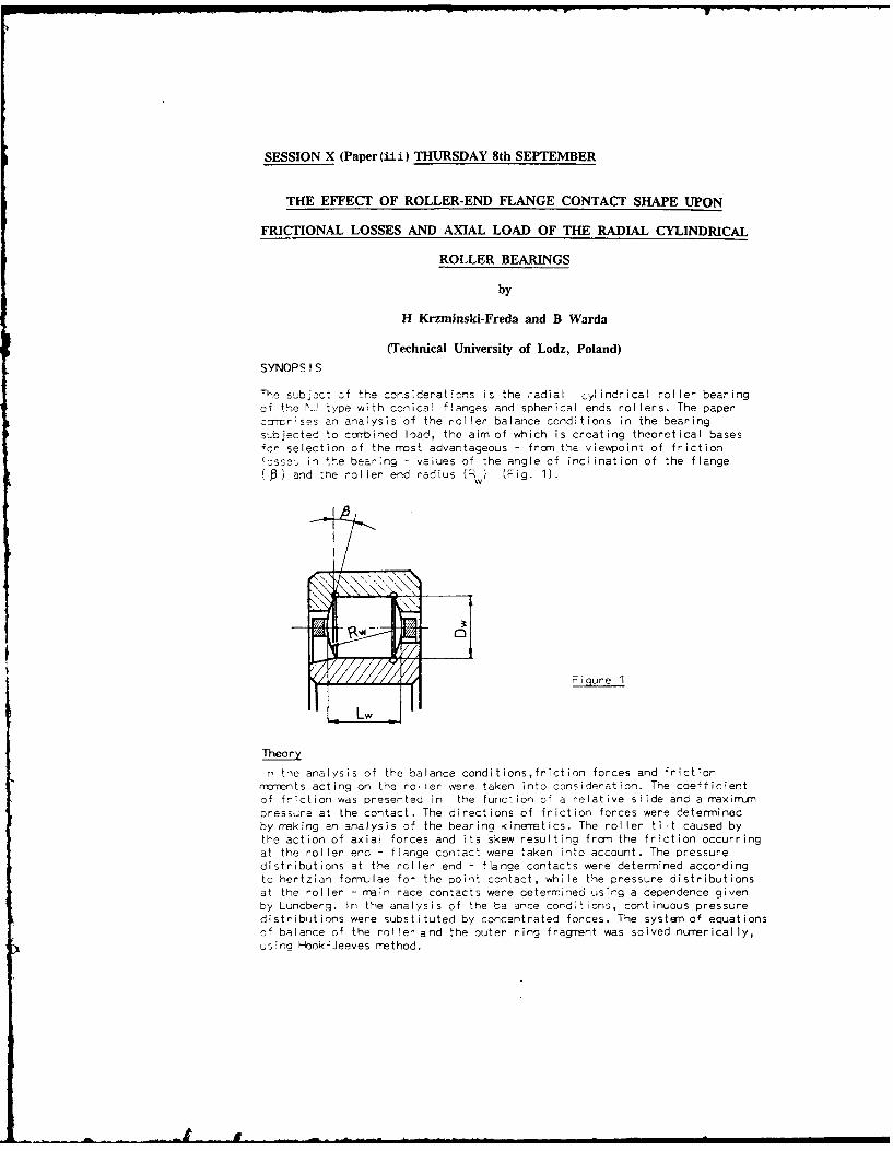
SESSION X (Paper (ii ) THURSDAY 8th SEPTEMBER
THE EFFECT OF ROLLER-END FLANGE CONTACT SHAPE UPON
FRICTIONAL LOSSES AND AXIAL LOAD OF THE RADIAL CYLINDRICAL
ROLLER BEARINGS
by
H Krzminski-Freda and B Warda
(Technical University of Lodz, Poland)
SYNOPSIS
The subjcct 3f the consderatins is the radial cylindrical roller bearingof the 1'. type with conical flanges and spherical ends rollers. The paperccrmr;ses an analysis of the roller balance conditions in the bearingsubjected to corrbined load, the aim of which is creating theoretical basesfor selection of the most advantageous - from the viewpoint of friction!csses in the bearing - values of the angle of incination of the flange( a end the roller end radius (Rw) (Fig. 1).
w
01
Figure I
Lw
Theory
in the analysis of the balance conditions,friction forces and frictionncrrents acting on the roller were taken into consideration. The coefficientof friction was presented in the function of a relative slide and a raxinimpressure at the contact. The directions of friction forces were determinedby naking an analysis of the bearing kinematics. The roller tilt caused bythe action of axial forces and its skew resulting from the friction occurringat the roller end - flange contact were taken into account. The pressuredistributions at the roller end - flange contacts were determined accordingto hertzian forrrulae for the point contact, while the pressure distributionsat the roller - main race contacts were determined using a dependence givenby Lundberg. In the analysis of the balance corditions, continuous pressuredistribuitions were substituted by concentrated forces. The system of equationscf balance of the roller and the outer ring fragment was solved nurrerically,us:no Hlook-Jeeves method.
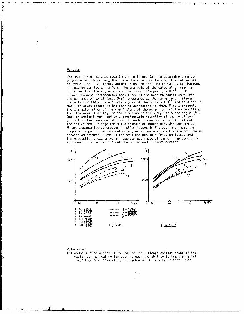
Results
The solution of balance equations rmade it possible to determine a nLrrberof pararreters describing the roller balance condition for the set valuesof radial and axial forces acting on one roller, and to make distributionsof load on particular rollers. The analysis of the calculation resultshas shown that the angles of inclination of flanges = 0.40 - 0.60ensure the most advantageous conditions of the bearing operation withina wide range of axial load. Small pressures at the roller end - flangecontacts (-250 NPa), small skew angles of the rollers (-T1) and as a resultsmall fricticn losses in the bearing correspond to them. Fig. 2 presentsthe characteristics of the coefficient of the rraent of friction resultingfrom the axial load (f2 ) in the function of the FQ/Fr ratio and angle •Smaller angles3 may lead to a considerable reduction of the inlet zoneor to its disappearance, which will render formation of an oil film atthe roller end - flange contact difficult or irrmossible. Greater angles0 are acccmpanied by greater friction losses in the bearing. Thus, theproposed range of the inclination angles allows one to achieve a corrpromisebetween an attempt to ensure the smallest possible friction losses and
the necessity to guarantee an appropriate shape of the oil gap conduciveto formation of an oil film at the roller end - flange contact.
1002 2 0.002 52
0.001 0.001:: -
0 Q 0.5 10 F/F 0 0.1 Q5 to F/Fr
1 NJ 2308E .... p- 19103"2 WJ2316E -9550"3 NJ 2324E p 0.4775"4 NJ 316E5 NJ 2216E6 NJ 216E Fr/C -0.11 Figure 2
ReferencesT1) WAFA B. "The effect of the roller end - flange contact shape of the
radial cylindrical roller bearing upon the ability to transfer axialload" (doctoral thesis), L6di: Technical University of L6di, 1987.
SESSION X (Paper (iv) - THURSDAY 8th SEPTEMBER
THE STUDY OF ROLLER END AND
GUIDING SHOULDER CONSTRUCTION OF ROLLER BEARINGS
by
M Li and S Wen
(Tsinghua University, Beijing, China)
SYNOPSIS
This paper deals with the roller end and guiding shoulder constructionof roller bearings on the basis of M{L theory and experimentalanalysis. An orthogonal test dealing with the main effect factors offriction torque and temperature increasing has been done in a widescope. Optimized roller end and guiding shoulder construction which canimprove the lubrication condition has been obtained, it is shown thatthe axial load carrying capacity of the new construction can beincreased by 5-10 times, compared with the usual ones.
Theoretical and Experimental Analysis
For roller bearing, the axial loads are carried by roller ends andguiding shoulders. Usually, the roller ends and guiding shoulders ofcommercial products are flat in shape, MiL film can not exist in such astate, and thus the axial load carrying capacity of these bearings isier-j small. in order that the roller bearing can be used in a greatradial load combined with a certain axial load case, theoretical andexperimental analysis has been done to find the possible goodconstruetion of the roller ends and guiding shoulders.
In theoretical analysis, numerical solutions of the EHL filmbetween conical-to-conical surfaces and spherical-to-conical surfaces ofroller ends and guiding shoulders of roller bearings are obtained.
In experimental analysis, eight sets of bearing samples are designedand manufiactcred of which the roller ends and guiding shoulders aredifferent in shape. The test bearings were running with 0-3000 rpm speedunder different load conditions. The contact surface temperature on outerrace guiding shoulder is measured with thermo-couples, the bodytemperature of outer ring is measured with four mercury thermometerswhich contact directly with the outer ring. The friction torque ismeasured with a torque transducer. In order to ensure the comparibilityof testing results, the testing conditions for any bearing sample areidentical.
Results
The conical-to-conical construction of roller ends and guiding shoulders(Fi-.l) is the best construction. The inclination angle of guidingshoulders is the key factor affecting axial load carrying capacity of this
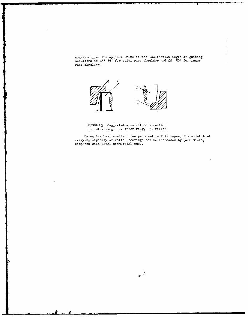
corstruction. The optimum value of the inclination angle of guidingshoulders is 45'-55' for outer race shoulder and 40'-50' for innerrace shoulder.
FIGUfC& I Conical-to-conical construction
Using the
best construction
proposed
in this paper,
the axial
load
carrying capacity of roller bearings can be increased by 5-10 times,compared with usual commercial ones.
J
SESSION XI (Paper (i)) - THURSDAY 8th SEPTEMBER
DYNAMICALLY LOADED JOURNAL BEARINGS:
A MODAL APPROACH TO EHL DESIGN ANALYSIS
by
A Kumar (Cornell University New York U S A)J F Booker (Cornell University New York U S A)P K Goenka (General Motors Research Laboratories Michigan U S A)
SYNOPSIS
A new mathematical model, based on the finite element method,is presented for transient elastohydrodynamic lubrication analysis.
Relative (differential) displacement of lubricated surfacesis represented by a (truncated) linear combinationof orthogonal modeshapes, which form the basis of bothrelative rigid body motion and relative elastic deformation.
The model combines hydrodynamic and elastostatic aspectsin a coupled initial value problem of relatively low order.
Idealized case studies are carried out to validate the model,which is then applied to a practical automotive connecting rodto demonstrate its versatility.
Problem Formulation
Consider a finite element discretization of a lubricant film.-al film thickness, clearance, and relative displacementsatisfy the n kinematic relations
and nodal pressures and forces satisfy the n eaivalence relations
Conventional 2-D finite element analysis of the lubricant film(for specified clearance, boundary conditions, and cavitation)
(d,t) a + ]( ,t) = -X
Conventional 3-D finite element analysis of the structure(for specified boundary conditions) under k external forcesgives the n elastostatic relations
where the (relative) stiffness is both symmetric and singular.
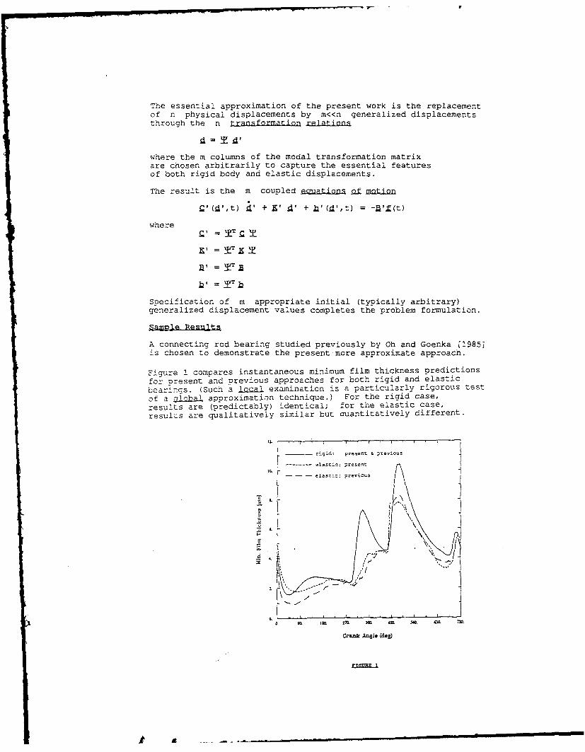
The essential approximation of the present work is the replacementof n physical displacements by m<<n generalized displacementsthrough the n transformation relations
a= I '
where the m columns of the modal transformation matrixare chosen arbitrarily to capture the essential featuresof both rigid body and elastic displacements.
The result is the m coupled ec uations af motion
CI(i ,t) ' + i' d' + ],(.d ,t) = (t)
where
Specification of m appropriate initial (typically arbitrary)generalized displacement values completes the problem formulation.
Sanmle Resulit
A connecting rod bearing studied previously by Oh and Goenka [1985]is chosen to demonstrate the present more approximate approach.
Figure 1 compares instantaneous minimum film thickness predictions
for present and previous approaches for both rigid and elasticbearings. (Such a lal examination is a particularly rigorous test
of a b approximation technique.) For the rigid case,results are (predictably) identical; for the elastic case,
results are qualitatively similar but cuantitatively different.
rigid: present & ptevious
....... e-astic: present
- --- elastic: previous
6.
E
6 K!7.
Crank Angle (deg)
k~rrr 1
SESSION XI - (Paper (ii)) - THURSDAY 8th SEPTEMBER
SHAPE DEFECTS AND MISALIGNMENT EFFETSIN CONNECTING-ROD BEARINGS
by
P Maspeyrot and J Frene
(University of Poitiers France)
SYNOPSIS
Connecting-rod and crankshaft bearings in petrol or diesel engitesare subjected to very Important dynasic loading. The Importance of theanalysis of this problem is obvious by the number of papers published In thisarea.
In this paper, the effects of the radial clearance in a perfectbearing under dynamic loading Is shown. Then the effects of shape defects ofthe journal bearing (journal with a taper or a parabolic axial profiles) orthe aisalignment of the journal are studied.
The misalignment introduces two supplementary parameters : 6, theangle between the eccentricity direction and the journal central Ireprojection and 6, the non-dimensionnal magnitude of the projection of thecomplete journal centreline onto the mid-plane. The misalignment is constritand the Journal Is assumed to rotate about Its own centreline.
THEORY
The film geometry equation for any axial nd angular position canbe written as follows :
h(9,z)- C + c. cos e + f(e z)
where f(Oz) is depending on the defect.The Reynolds equation has been written using the mobility method
of BOOKER (1) :
a [3 Ip Rr2a613 8 12 cos (0 4 a) - - sin a sin(a -g)80 80 L 19z 8 z co
Solution of this equation is obtained by an Iterative method todetermine a, the mobility angle, and by finite differences with theGauss-Siedel method and the Reynolds boundary conditions to obtain thepressure field. Knowing the pressure field, numerical integrations give thefriction torque and the axial flow,
RESULTS
Numerical results are obtained for the big-end connecting-rodbearing, without circumferential groove, of the RUSTON-HORNSBY 6 VER-X Mk I]]diesel engine.
The curve of the effect of the radial clearance on the minimum filmthickness has a similar aspect than for a bearing under steady stateconditions.In table I details of the Influence of shape defects ormisalignments on the minimum film thickness are given :
Minimum film thickness (pm)
Perfect bearing 8.5
Tapered bearing 7.8
Parabolic bearing 7.8
Horizontal misalignment 3.6
Vertical misalignment 4.5
TABLE I
REFERENCE
(1) BOOKER,J.,F. "Dynamically Loaded Journal Bearings: NumericalApllication of the Mobility Method ."JCLT-ASME,series F,Jan 1971.
Al i
SESSION XI (Paper (iii) - THURSDAY 8th SEPTEMBER
TRANSIENT DYNAMICS OF ENGINE BEARING SYSTEMS
by
S Boedo (Borg-Warner Automotive, Inc. New York U S A)and
J F Booker (Cornell University, New York, U S A)
SYNOPSIS
This paper formulates a realistic single-cylinder engine model for
investigation of journal bearing response to transient duty cycle variation.
In particular, the authors have investigated transient bearing orbit
response to aperiodic cylinder pressure variation ("throttling").
Problem Formulation
The analysis starts with the development of an engine and "external"
environment model dynamically equivalent to the corresponding actual
rigid-body engine and actual engine application, respectively. Engine
components are modelled as massless rigid bodies embedded with discrete
point masses fFig. 12, The variation of cylinder pressure p with crankangle
0 is assuned specified.
x
I /
M2
/
+
F 1 P11rl L5
FIGURE 1
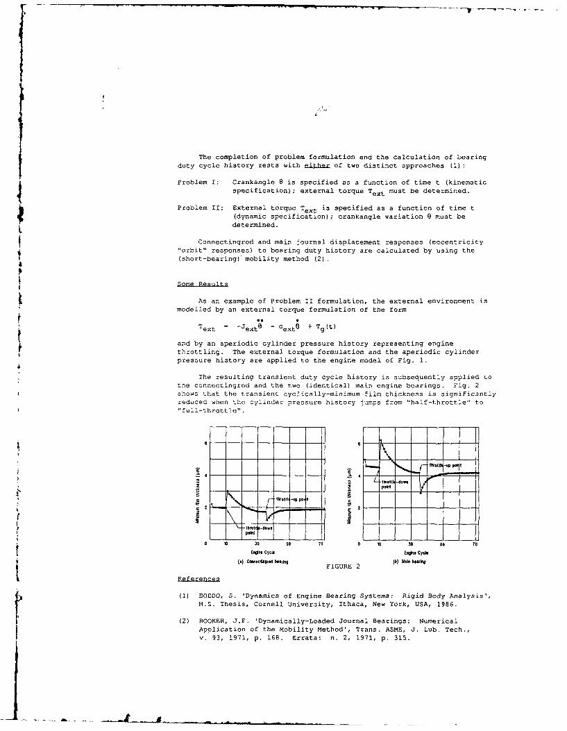
The completion of problem formulation and the calculation of bearingduty cycle history rests with either of two distinct approaches (1):
Problem I: Crankangle 0 is specified as a function of time t (kinematic
specification); external torque Text must be determined.
Problem II: External torque Text is specified as a function of time t
(dynamic specification); crankangle variation 0 must be
determined.
$ Connectingrod and main journal displacement responses (eccentricity"orbit" responses) to bearing duty history are calculated by using the
(short-bearing) mobility method (2).
Some Results
As an example of Problem II formulation, the external environment ismodelled by an external torque formulation of the form
ext = -Jexte - Cext + Tg(t)
and by an aperiodic cylinder pressure history representing enginethrottling. The external torque formulation and the aperiodic cylinderpressure history are applied to the engine model of Fig. 1.
The resulting transient duty cycle history is subsequently applied to
the connectingrod and the two (identical) main engine bearings. Fig. 2shows that the transient cyclically-minimum film thickness is significantly
reduced when the cylinder pressure history jumps from "half-throttle" to"full-throttle".
Z\ 4Well - d-dOWl
a30 50 0 0 0 3 60 To
Engie Cycl Engin Cycle
S i FIGURE 2 -
(1) BOEDO, S. 'Dynamics of Engine Bearing Systems: Rigid Body Analysis',
M.S. Thesis, Cornell University, Ithaca, New York, USA, 1986.
(2) BOOKER, J.F. 'Dynamically-Loaded Journal Bearings: NumericalApplication of the Mobility Method', Trans. ASME, J. Lub. Tech.,
v. 93, 1971, p. 168. Errata: n. 2, 1971, p. 315.
- - -
SESSION M - (Paper (iv)) - rHURSDAY 8th SEPTEMBER
THERMAL CONSIDERATIONS IN ENGINE BEARINGS
by
G A Clayton and C M Taylor
(The University of Leeds U K)
SYNOPSIS
In the analysis of dynamically loaded journal bearings, such as those occurring in theinternal combustion engine, the prediction of shaft orbit and the cyclic minimum oil filmthickness has attracted most attention. Relatively little effort has been expended in developingtechniques to give a reliable estimation of the effective lubricant temperature through thermalanalysis. One reason for this relates to the lack of precision of the determination of lubricantflow rate and heat dissipation to the oil, two factors which are important in thermalcalculations.
The present study has been directed towards a thermal analysis of the Ruston and Hornsby6VEB Mk III big-end bearing; this connecting rod bearing has become a standard test case forthose concerned with engine bearing analysis. Straightforward predictions of flow rate and powerloss based on the commonly adopted short bearing analysis have been undertaken leading to aniterative internal balance to predict the effective operating temperature and viscosity (1,2,3).In addition a more rigorous analysis based on considerations of oil film history has beenundertaken (4).
The results of the simple approach were found to give good agreement with those obtainedby the more complex analysis. It is proposed to undertake experimental work in the near futureto provide a validation of the theoretical model adopted.
Theor
(a) For the rapid solution technique the journal orbit was determined from short bearingtheory using an assumed effective oil temperature. The oil flow rate and power loss werecalculated at 72 points in the orbit from the following expressions and numerical integrationused to sum for one engine cycle.
FM (Cd / d)2 Cd
Q = 2 "1 (I) Hydrodynamic Flow
0.0315 P" Cd 3 ) / G
QP =.15 1.5 c2 + 1) (1) Pressure Flow
Ii ~rld3 b (Ct - ) 2 J1 "
H4 Cd (3) Shear Power Loss
: ~ ~ ~~~~ ~~~~~~ C d iimI I•I l~II m m n
••lmmmml =n
HsQ = F-V cos / (4) Squeeze Power Loss
A new effective temperature was determined using the following expressionar I an, ;,craive loop repeated until satisfactory convergence.
HT. = - + T (5)
(b) The analysis incorporating oil film testing effects involved complexconsiderations concerning the true extent of the cavitation region. This will bediscussed in detail.
Results
Some typical results are shown below.
rcI",'-,F-- n_ . r 5 I o.
a _ __1 __
S1-0 . -- I
References
(1) F A Martin and C S Lee, "Feed Pressure Flow in Plain Journal Bearings".Trans. A.S.L.E.. Voi 23, 3, 1983, pp 381-392.
(2) F A Martin, 'Friction in Internal Combustion Engines", I.Mech.E.,Conference - Combustion Engines-R-duction of Friction and Wear, PaperC67/85, 1985. pp 1-17.
(3) F A Martin. "Developments in Engi e Bearings", Proc. 9th Leeds-LyonSymposium on Tribology - Tribolog3 of Reciprocating Engines, 1983, pp9-36.
(4) G I Jones. *Crankshaft Bearings: %A Film History", Ibid, pp 83-88.
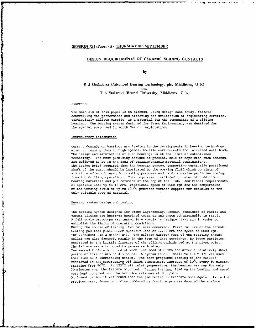
SESSION XII (Paper (i) - THURSDAY 8th SEPTEMBER
DESIGN REQUIREMENTS OF CERAMIC SLIDING CONTACTS
by
R J Godzdawa (Advanced Bearing Technology, plc, Middlesex, U K)and
T A Stolarski (Brunel University, Middlesex, U K)
SYNOPSIS
The main aim of this paper is to discuss, using design case study, factorscontrolling the performance and affecting the utilization of engineering ceramics,particularly silicon carbide, as a material for the components of a slidingbearing. The bearing system designed for Framo Engineering, was destined forthe special pump used in North Sea oil exploration.
Introductory information
Current demands on bearings are leading to the developments in bearing technologyaimed at running them at high speeds, hostile environments and increased unit loads.The design and manufacture of such bearings is at the limit of establishedtechnology. The most promising designs at present, able to cope with such demands,are believed to be in the area of ceramic/ceramic material combinations.The design brief required that the bearing system, supporting vertically positionedshaft of the pump, should be lubricated by the working fluid which consists ofa mixture of an oil used for cooling purposes and hard, abrasive particles comingfrom the drilling operation. This requirement excluded a number of traditionalbearing materials and put ceramics at the top of the list. Additional requirementsof specific load up to 13 MPa, rotational speed of 6000 rpm and the temperatureof the working fluid of up to 1300C provided further support for ceramics as theonly suitable type of material.
Bearing system design and testing
The bearing system designed for Framo Engineering, Norway, consisted of radial andthrust tilting pad bearings combined together and shown schematically in Fig.l.A full scale prototype was tested in a specially designed test rig in order toestablish the limits of operating conditions.During the coursF of testing, two failures occurred. First failure of the thrustbearing pad took place under specifir load of 12.75 MPa and speed of 6000 rpm.The lubricant was a diesel oil. The silicon carbide face of the rotating thrustcollar was also damaged, mainly in the form of deep scratches, by loose particlesgenerated by the brittle fracture of the silicon carbide pad at the pivot point.The failure was attributed to excessive loading.The second failure occurred at much less load of 8 MPa and after a relatively shortperiod of time of around 4.5 hours. A hydraulic oil (Shell Tellus T-37) was usedthis time as a lubricating medium. The test programme leading to the failureconsisted in the progressive oil inlet temperature increase of 10 C every 60 minutesstarting from 80 C. At 1200C oil inlet temperature, the bearing was run for only30 minutes when the failure occurred. During testing, load on the bearing and speedwere kept constant and the oil flow rate was at 38 1/min.On investigation it was found that the pad failed in fracture mode again. As in the
previous case, loose particles produced by fracture process damaged the surface
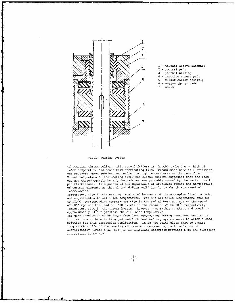
- .- 7
~2i3
1 - journal sleeve assembly2 - journal pads
3 - journal housing4 - inactive thrust pads
5 5 - thrust collar assembly6 - active thrust pads7 - shaft
Fig.1 Bearing system
of rotating thrust collar. This second failure is thought to be due to high oilinlet temperature and hence thin lubricating film. Predominant mode of lubricationwas probably mixed lubrication leading to high temperatures at the interface.Visual inspection of the bearing after the second failure suggested that the loadwas ot shared equally by all the pads and was probably caused by the variations inpad thicknesses. This points to the importance of precision during the manufactureof ceramic elements as they do not deform sufficiently to absorb any eventualinaccuracies.Temperature rise in the bearing, monitored by means of thermocouples fixed to pads,was consistent with oil inlet temperature. For the oil inlet temperature from 80to 1200C, corresponding temperature rise in the radial bearing, run at the speedof 6000 rpm and the load of 1000 N, was in the range of 20 to 300 C respectively.Temperature rise in the thrust bearing, however, was rather constant and equal toapproximately 34 C regardless the oil inlet temperature.The main conclusion to be drawn from data accumulated during prototype testing isthat silicon carbide tilting pad radial/thrust bearing system seems to offer a goodsolution for this particular application. It is now quite clear that to ensurelong service life of the bearing with ceramic components, unit loads can besignificantly higher than that for conventional materials provided that the effective
lubrication is secured.
SESSION XII (Paper (ii) - THURSDAY 8th SEPTEMBER
UNLUBRICATED WEAR AND FRICTION BEHAVIOUR
OF ALUMINA AND SILICON CARBIDE CERAMICS
by
G Kapelski, F Platon and P Boch
(Ecole National Suprieure de Cgramique Industrielle, Limoges, France)
SY'TOP T S
Ceramics behave as brittle materials at low and medium temperatures.Fracture suddenly develops when the stress field reaches a critical state.This critical state depends on many parameters. It also depends on whetherthe streso field is uniaxial or multiaxial. Therefore, it is difficult tocorrelate the damage which is observed in tribological studies of ceramics- which corresponds to a multiaxial stress state - with macroscopic data.in particular, the "tribological strength", understood as the yield pointbeyond which local cracks develop, is generally higher than themacroscopic strength (as can be determined using, for ,nstance, a unaxiaibeod~n test).
Ith case of wear and friction tests with high contactpressures, cracking of the friction track can develop during the verybeginning of the test. The extont of damage of the contact surfaces andthe orcouction of wear debris are very sensitive to such cracking. Thisceans that the entire life of a tribological couple can be affected by thefirst few seconds, and that the wear and friction behaviour of a ceramic-to-ceramic couple is very dependent on an eventual overload.
Ths work was thus focused on the study of the damage which canoccur during the first few instants of the life of a ceramic-to-ceramiccouple, tested using a ball-on-disc configuration. Seveai ceraicmaserials were studied, in particular silicon carbide and alumina. Thefriction tests, called "dynamic" because thcy involve the displacement ofthe ball on the disc, were completed by indentation tests, called "static"because thev simply correspond to loading the disc by the ball.
For the static indentation tests, and assuming that the materialbehaves in a perfectly elastic manner, the maximum of the principaltensile stress at the surface is l) :
01, = (l-2v)/(2n)(0.75 k F/E) -2 2 F,'
where F is the normal load, : and v are Young's modulus and Poisson'sratic of th2 disc material, R is the ball radius, and k is a parameterwhich is a functton of the elastic constants of both the disc and the ball
materials. Fracture develops when OIs reaches a critical value : alst.This value was found to be about 1200 MPa for alumina as well as for
silicon carbide, which corresponds to loads of 1250 N (for AIO3) and430 Nr (for SiC). The respective macroscopic strengths were 235 1!Pa and450 Y s. i.. about one third only of the 'tribological str ngths". Forthe jynamic friction tests, the maxioum value of the principal tensile
stress (O) becomes a function of the coefficient of friction (f). At therear of the friction contact, this maximum is (2,3)
aid = (ais)(l+k, f)
where k, is a function of Poisson's ratio of the disc raterial. Fracturedevelops when Old reaches a critical value, 01dj, which was found to beapproximately equal to 0is. it was verified that when the load on theball is sufficient to give old = Cldf, a crack array develops during the
first revolution of the ball on the disc. Data are discussed, and theevolution of the crack array as the test procedes is described.
References
(1) JOHNSON K.L. 'Hertz Theory of Elastic Contact', 90-104, 'Pressure
Applied to a Circular Region', 56-63, in Contact Nechanics, the PressSyndicate of the University of Cambridge Publ.,(1935).
(2) HA:1ILTON G..,!. end GOODMIAN L.E., 'The Stress Field Created by aCircular Sliding Contact', in J. Appl. Mech., 371-374, (1966).
(3) LAWII B.R., 'Partial Cone Crack Deformation in Britzle Material Loadedwith a Spherical indenter', in Proc. Roy. Soc., A299, 307-316, (1967).
i£
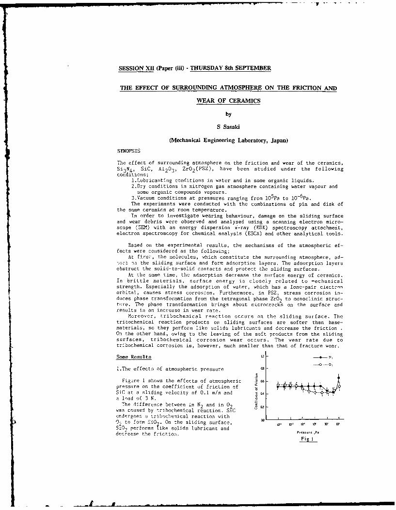
SESSION X11 (Paper (iii) - THURSDAY 8th SEPTEMBER
THE EFFECT OF SURROUNDING ATMOSPHERE ON THE FRICTION AND
WEAR OF CERAMICS
by
S Sasaki
(Mechanical Engineering Laboratory, Japan)
SYNOPSIS
The effect of surrounding atmosphere on the friction and wear of the ceramics,Si3 N4, SiC, A1 203 , ZrO 2 (PSZ), have been studied under the followingconditions;
1.Lubricanting conditions in water and in some organic liquids.2.Dry conditions in nitrogen gas atmosphere containing water vapour and
some organic compounds vapours.3.Vacuum conditions at pressures ranging from 105pa to 1-6Pa.The experiments were conducted with the combinations of pin and disk of
the same ceramics at room temperature.In order to investigate wearing behaviour, damage on the sliding surface
and wear debris were observed and analysed using a scanning electron micro-scope (SEM) with an energy dispersion X-ray (EDX) spectroscopy attachment,electron spectroscopy for chemical analysis (ESCA) and other analytical tools.
Eased on the experimental results, the mechanisms of the atmospheric ef-fects were considered as the following;
At first, the molecules, which constitute the surrounding atmosphere, ad-on the sliding surface and form adsorption layers. The adsorption layers
obstruct the solid-to-solid contacts and protect the sliding surfaces.At the same time, the adsorption decrease the surface energy of ceramics.
In brittle materials, surface energy is closely related to mechanicalstrength. Especially the adsorption of water, which has a lone-pair eiectronorbital, causes stress corrosion. Furthermore, in PSZ, stress corrosion in-duces phase transformation from the tetragonal phase ZrO 2 to monoclinic struc-ture. The phase transformation brings about microcracks on the surface andresults in an increase in wear rate.
Moreover, tribochemical reaction occurs on the sliding surface. Thetribochemical reaction products on sliding surfaces are softer than base-materials, so they perform like solids lubricants and decrease the friction .On the other hand, owing to the leaving of the soft products from the slidingsurfaces, tribochemical corrosion wear occurs. The wear rate due totribochemical corrosion is, however, much smaller than that of fracture wear.
Some Results I-
---- 0...-0,
!.The effects of atmospheric pressure
Figure 1 shows the effects of atmospheric .6 -
pressure on the coefficient of friction of - ..
SiC at a sliding velocity of 0.1 m/s and Z N
a load of 3 N.The difference between in N2 and in 02
was caused by tribochemical reaction. SiC
undergoes a tribochemical reaction with02 to form SiO On the sliding surface, 00 0" Q lSiC0, performs fike solids lubricant and P, Pa
decrease the friction. PsU,,Pi
' ~~~~ ~~~ ~ ~~ ~~~~~ ig .. .1amn mmllmm••d m m m un
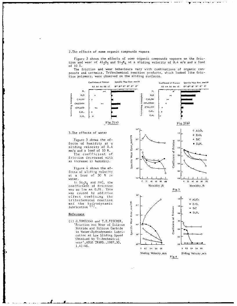
2.The effects of some organic compounds vapors
Figure 2 shows the effects of some organic compounds vapours on the fric-tion and wear of A1203 and Si3N4 at a sliding velocity of 0.4 m/s and a loadof 10 N.
The friction and wear behaviours vary with combinations of organic com-pounds and ceramics. Tribochemical reaction products, which looked like fric-tion polymers, were observed on the sliding surfaces.
Coeffici.t of Friction Specific Wear Rate .ome,'i Coefficient of Friction Specific Wear Rate .mttiN
0.2 0.4 0.6 0.8 1.0 io 10 10, 0 101, 10, 0.2 0.4 0.6 0A 1O 10"u I0 I 0 10 to' IV
N, i N, H1
Hto H'O
CtH,O0 CH-,0 - i
< CHCOOH i CH 001i
(CHf,) CO - E (CH,):CO
CH. C.H.
Fig.2(a) Fig.2(b)
10" 0 3
3.The effects of water 1.2
z o ZrO.Figure 3 shows the ef- i0, SiC
fects of humidity at a 0 . , SitN,
sliding velocity of 0.4 - "t
mm/s and a load of 10 N. 0 0!
The coefficient of 'F: 0.6friction decreased with 101"an increase in humidity.
'4 0 4
Figure 4 shows the ef- 1, a-, c
fects of sliding velocity 0.2
at a load of 50 N inwater. I'" I I I I o . I
In Si3 N4 and SiC, the 0 5 40 60 8 oI 020 40 60 80 IN
coefficient of friction Humidity,% Humidity,%was as low as 0.01. This Fig.3was caused by additiveeffect combining the 1,
tribochemical reaction 1-2 - 0 Al-0,
and the hvfrodynamic z 0 0 ZrO1lubrication 1.0. E L0EL a sic
Reference -0 * Si3 N.
0(1) H.TOMIZAWA and T.E.FISCHER, - 0.6
'Friction and Wear of Silicon i".Nitride and Silicon Carbide 0.4
in Water:Hydrodynamic Lubri- _cation at Low Sliding Speed
0o
Obtained by Tribochemical 0.0.2
wear',ASLE TRANS.,1987,30, 0.0
1,41-46.0 3.Z 0.4 0.6 0.8 0 0. 0.
4 0.6 08
Slidi=& Velocity ,m/s Sliding Velocity m/s
Fig.4
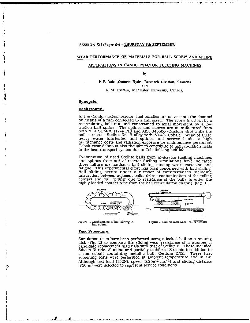
? --
SESSION XII (Paper (iv) - THURSDAY 8th SEPTEMBER
WEAR PERFORMANCE OF MATERIALS FOR BALL SCREW AND SPLINE
APPLICATIONS IN CANDU REACTOR FUELLING MACHINES
by
P E Dale (Ontario Hydro Research Division, Canada)and
R M Tristani, McMaster University, Canada)
Synopsis.
Background,
In the Candu nuclear reactor, fuel bundles are moved into the channelby means of a ram connected to a ball screw. The screw is driven by arecirculating ball nut and constrained to axial movement by a lowfriction ball spline. The splines and screws are manufactured fromboth AISI S17400 (17-4 PH) and AISI S45500 (Custom 455) while theballs are cast Stellite No. 6 alloy with 59.4% Cobalt. Wear of theseheavy water lubricated ball splines and screws leads to highmintenance costs and radiation exposure for maintenance personnel.Cobalt wear debris is also thought to contribute to high radiation fieldsin the heat transport system due to Cobalts' long half-life.
Examination of used Stellite balls from in-service fuelling machinesand splines from out of reactor fuelling simulations have indicatedthree failure mechanisms; ball sliding causing wear, corrosion andfatigue. This experimental effort has been concerned with ball sliding.Ball sliding occurs under a number of circumstances includinginteraction between adjacent balls, debris contamination of the rollingcontact and ball pling" due to resistance of the balls to enter thehighly loaded contact zone from the ball recirculation channel (Fig. 1).
Figure 1. Mechanisms of ball sliding in Figure 2. Ball on disk wear test seeatic.ball spline.
Test Procedure.
Simulation tests have been performed using a locked ball on a rotatingdisk (Fig. 2) to compare the sliding wear resistance of a number ofcandidate replacement materials with that of Stellite 6. These includedSilicon Nitride, Alumina and partially stabilized Zirconia in addition toa non-cobalt containing metallic ball. Cenium ZNZ. These firstscreening tests were performed at ambient temperature and in air.Although test load (152N), speed (5.25e-2 ms-I) and sliding distance
1) (756 mn) were selected to represent service conditions.
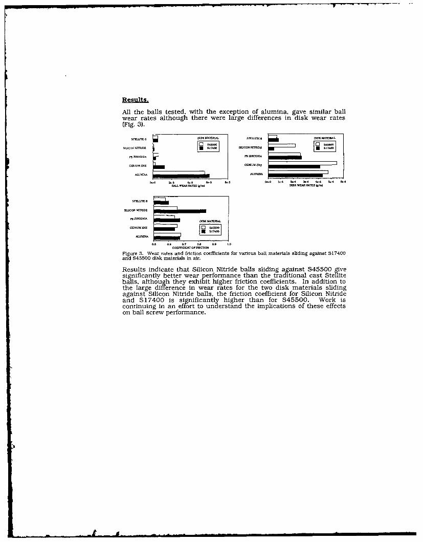
Results.
All the balls tested, with the exception of alumina, gave similar ballwear rates although there were large differences in disk wear rates(Fig. 3).
STETE6 DISKMIATEM STLT j MMIA
SIUCON M41D *S700 SICON NM510 E MiO
PS SRCM1A PS flRCONLA
CETIUM PSZ CEMUM DZ
ALLMINA ALUMINA ________________
00 U.5 4.S &.3 8.5 0..0 1.4 2.4 3.4 4.4 5.4 &.4lAiL. WEAR RATES Wd DISK WEAR RATES Ws..j
STLJE 0 5 0. 0. 0. 0. ,
SIUCOMM.TRD C _______ Ol__
n ZIRCONIA
CUMLW MVZ o -
ALUAPS4
0.5 0.0 0.7 08 0" 1.0COEMFLSOPFSICflO
Figure 3. Wear rates and friction coefficients for various ball materials sliding against $17400and S45500 disk materials in air.
Results indicate that Silicon Nitride balls sliding against S45500 givesignificantly better wear performance than the traditional cast Stelliteballs, although they exhibit higher friction coefficients. In addition tothe large difference in wear rates for the two disk materials slidingagainst Silicon Nitride balls, the friction coefficient for Silicon Nitrideand S17400 is significantly higher than for S45500. Work iscontinuing in an effort to understand the implications of these effectson ball screw performance.
6t
SESSION XIII - (Paper (i)) - FRIDAY 9th SEPTEMBER
TRIBOLOGICAL DESIGN - THE POWER GENERATION INDUSTRY
by
P G Morton
(G E C Stafford U K)
SYNOPSIS
Many machines and components used in the power generation field arecommon to a wide range of plant. What is unique in this field isassociated with the main power line-out, i.e. the combination of primemover and electrical generator usually on a single shafting system.Individual machines have their rotors solidly coupled and their statorsare also structurally coupled.
Power plant is distinguished in the -' by its size, mass and poweroutput all of which have affected ?sign of machine elements.Problems emerging over the past 30 ye , have been almost entirelyassociated with inccreases in size and power. The paper deals withdesign problems in three types of power plant viz steam turbosets,hydroelectric generators and gas turbine plant. The subject areas areas follows.
Journal Bearings
Journal bearings have increased in duty over the years and the treatmentof their steady state characteristics has become more sophisticated overthe years. Thermohydrodynamic theory has improved from the earlier workof Christopheron to include now the effect of non-laminar flow, oilreciruclation, boundary reformation, cavitation, conduction into shaftand bush, angular and tranverse misalignment and more recentlythermoeleastic and elastic distortion. The dynamic characteristics andtheir influence on system stability have also benefited from muchtheoretical and experimental research so that it is possible to predictthe contributions of the bearings to the system dynamics with reasonableaccuracy, in some cases making allowance for non-linear effects. Thehistory is briefly examined and also the various attempts to adjust oilfilm profiles to improve both steady and dynamic characteristics.
Seals and Glands
Seals and glands affect rotating systems in two ways. First they add tothe system instability by 'negative damping' mechanisms. Second, byshaft rubbing they produce 'synchronous instability' in an unstablespiral vibration vector.
The approach of various authors to designing away from these problems isreviewed.
Thrust Bearings
The largest and most heavily loaded thrust bearings are those supportingvertical hydroelastic shafts. In contradistinction to journal bearings,thrust bearing analyses have included the thermoelastic effect for manyyears. Some of the problems in thrust bearing design dealt with in theliterature are reviewed, including the opposing effects of elastic andthermoelastic pad distortion the influence of water cooling andtransient effects.
Movement of Turbine Supports
Due to changes in operating conditions at the turbine end of the steamturboset allowance has to be made for expansion in all directions.Relative movement has to be allowed for internally in the HP and IPturbines and externally on both turbine and generator supports. Commentis made on publications on the attendant wear problem arising frommovements at the interfaces and the choice of materials to ensure themaintenance of good alignment and reduction in internal stresses.
Effects of Internal Friction in Rotors
Papers relating to movements in the windings of generator rotors leadingto insulation wear and fretting fatigue are commented on. Instabilityarising from rotating friction is also covered.
Effects of Friction in Laminated Electrical Machines
Several publications have dealt with frictional effects on thelaminations of generator stators and certain laminated rotors resultingfrom relative conductor/stack movements. These are briefly discussed.
LO
SESSION XIII (Paper (ii) - FRIDAY 9th SEPTEMBER
TRIBOLOGICAL DESIGN AND ASSESSMENT -
The Nuclear Industry
by
T C Chivers
SYNOPSIS (CEGB, Berkeley Nuclear Laboratories, U K)
The Operational requirements and/or environmental considerations withinthe Nuclear Industry frequently invalidate those design codes that deal with
the tribology of mechanism elements. As a consequence, the Industry has had4to evolve its own methods. Frequently these have to be itterative, ie a
design is produced and then assessed. In some instances it will be necessary
to redesign or modify the operational/maintenance/monitoring strategy to dealwith uncertainties.
Within most areas of nuclear reactors the use of conventional lubricants
is prohibited and hence design to cope with unlubricated wear is a majorinterest. In the paper the current assessment strategies will be outlined.For some components the assessment is based or a simplified "Archardian"
approach, viz:-
Wear Volume = K.L.S.
Where K is a specific wear rate, L is the interfacial load and S the totalsliding distance.
However, the high power densities encountered within nuclear reactors
frequently results in flow or noise induced relative movements of components.
This complicates the determination of loading and sliding distanceinformation, and these parameters influence specific wear rates. Hence wear
volume determination can be very uncertain. To determine these input
parameters requires close collaboration between various specialists. Ingeneral the strategy adopted is to determine acceptable bounds and thepositive identification of the appropriate limiting criterion. Examples willbe given where these approaches are employed.
Assessments as outlined above relate to individual contact geometries.However, in some instances, such as control mechanisms or valves, componenttests are conducted to validate design. In these tests the full duty cycle
and environmental conditions are simulated. Examples will be given where this
approach has identified the need for plant modifications, and the way that the
proposed changes have in turn been evaluated.
An important input into assessment proceduires are the consequences of
failure. Outage costs associated with loss of availability are high;reactor safety is of paramount importance. A high level of quality
assurance is, therefore, necessary in formulating recommendations. Peerreview and method/data endorsement is part of this process. Datarelating to a design or component tests are considered by an industry wide
committee of experts. Following agreement, recommendations will be made to
a parent body which includes design representatives. At this level the
usefulness of the advice is considered, and it is endorsed for use ifappropriate.
ta
SESSION XIII (Paper (iii) - FRIDAY 9th SEPTEMBER
TRIBOLOGICAL DESIGN - THE SPACECRAFT INDUSTRY
by
R A Rowntree, E W Roberts and M J Todd
(National Centre of Tribology, UKAEA, U K)
Abstract
Modern spacecraft abound with mechanisms where relative movementbetween contacting surfaces occur. Failure or abnormalperformance of such mechanisms can rapidly lead to loss of anexperiment or mechanism function; for critical items this canlead to complete failure of the spacecraft mission.
The designer of spacecraft mechanisms faces several 'hostile'conditions in which hardware must operate without any possibilityof repair, with extreme reliability, minimum mass and minimumpower consumption. The environmental design drivers include thehigh vacuum of space, temperature extremes of -2690C to +1500C,temperature differentials across rotating components of typically±550C, the launch vibration, the effect of zero (or near-zero)gravity, rapid depressurisation and particle radiation. Dependenton mission type satellite life is currently in the range 7 to 10years and even longer lives will soon be required.
This paper will examine the characteristics of the main types ofelectro-mechanical mechanisms used in spacecraft and theirtribological requirements. To give low friction and avoid severeadhesive wear in the space environment, specialised lubricantsare used. The techniques, properties and types of suitable solidand liquid lubricants will be described. Problematic areas andnew developments in space tribology will be highlighted. Toillustrate the fundamental role of tribology in spacecraftmechanism design, examples will be drawn from operating andcurrent designs of satellite. The paper stresses the need toconsider tribology as a fundamental part of the spacecraftmechanism design process and not something to be left in thespecification as 'TBD' (to be decided).
2:
2~
-~ ~ ~ --. -----
SESSION XIII (Paper (iv) - FRIDAY 9th SEPTEMBER
TRIBOLOGICAL DESIGN - THE ELECTRONICS INDUSTRY
by
E A Muijderman, F Bremer, P L Holster, A v Montfoort and A G Tangena
(Philips Research Laboratories and Philips Centre for Manufacturing Technology)(The Netherlands)
SYNOPSIS
The paper provides an impression of tribological research and development withinPhilips. We will First introduce Philips, then summarize the different tribologicalresearch areas and the existing design procedures and finally give a short de-scription of desirable future research work.
Philips is a multinational company with national organizations in more than 60countries. It has a turnover of 22 billion ECU and employs 340,000 people.
Tribological research and development work is mainly performed in the PhilipsResearch Labs. and at the Philips Centre for Manufacturing Technology (ClF).This work is largely concentrated in Eindhoven, the Netherlands.
For a description of the tribological activities and design procedures at Philips weprefer to use the classifications: full-film lubrication, mixed & boundary lubricationand dry-rurning systems.
Full-filin lubricationExternally pressurized air and oil bearings:In the research attention is focussed on the dynamic behaviour and on the con-struction of optimal (infinitely) stifT bearings. In the company numerous bearingsfor widely varying applications are in use.Spiral Groove Bearings (SGs)(Grease-lubricated SGI~s for the scanner motor of video recorders have been usedin mass production since 1978. Air-lubricated SGBs are used in the design of laserscanners, whereas oil-lubricated SGs for flywheels have shown a lifetime of morethan 20 years.Foil bearingsThis research investigatcs the tape-scanner system of video recorders, where thetape acts as an air-lubricated foil.
Mixed & boundary lubricationFor the selection of lubrication fluids we have a well-established routine. Problemsin this field are solved by functional tests. An important research topic is precisionmachining, which includes the machining process itself. machine dynamics, meas-urCieeit antid control and their interactions.
Dry-running systemsin this Field studies are made of material characterization, contact mechanics (foruse in wear models likc the 7cro-wcar model and Archards model), coatings andnignnctic recording. [he purpose of this work is twofold. Part of it has the natureof rcsearch, while other parts are more dcvelopment-oricnrtcd.
-. y
The network for transfer and acquisition of trihologica! knowledge within Philipswill he Mentinecd.
There is all coorMous amn10.t of trihological R&D) work which is of interest toP'hilips. HeIre we limit ourselves to the following:
- a uiversal, reliable, user-friendly prograimme package to design full-filmn hearings(like FIN packages for mechanical calculations)
-dynamic analysis of (aerostatic) bearing behaviour-analysis of the fundamentals of the failure of coatiiigf-development and characterizationl of new (tribo)materials-analysis of boundary lubrication (transition diagrams), so that research resuliscan i-c transferred to practical applications
-condlitions foi- zero wvear.
SESSION XIV (Paper (i) - FRIDAY 9th SEPTEMBER
OPTIMUM DESIGN AND AUTOMATIC DRAWING
OF RECESSED HYDROSTATIC BEARINGS
by
Xu Shangxian and Chen Baosheng
(Southwest University, Nanjing, China)
SYNOPSIS
The optimum design and automatic drawing of the hydrostaticbearing with any number of recesses are studied. For analysis andcalculation of the dynamic effects on the lands, the Reynolds'equation is directly solved by the finite difference method withinequal steps or finite element method.
In the optimum design of the bearing, there are someoptimization methods and several objective functions to be offered
to the users.Because several technical approaches are employed, itbecomes practicable to do the optimization of bearings by solvingthe Reynolds' equation directly.
To draw the bearing draught automatically, the interfacebetween the standard graphic software AUTO-CAD and the pro-gramming language is worked out.
THEORY
1. The mathematical model of the optimum design [1](1).The design variables in optimization are considered as:
X=fL/D,La/L,Lt/D, 0 ,K P7(2).There are several objective functions in the system, such
as load capacity,stiffness, flow rate, total power loss and totalpower loss/load capacity.
(3).It has to subject to these following constraints:(a). 1.2 >= L/D >=0.5 (b). 0.5 >= La/L >= 0.1(c). 7r/(2-No) >= Lt/D >= 0. (d). 0.9 >=# >= 0.(e). 12. >= K >= 0. (f). WNO >= Wo(g). p max >= p, >= pmin (h). Zmax >= >='min
2.The selection of optimization methodBecause the above mathematic model is a nonlinear problem and
it is difficult to describe the bearing performances (e.g. loadcapacity)and their derivatives by analytical functions, the directoptimization method seems to be more suitable for this kind ofproblem.
In order to make the optimum design available for use , aseries of technical approaches are applied to save computer;ime, such as the reasonable selection of the initial values,the automatical modification of the superrelaxation factors andthe higher and/or lower accuracy iteration technique.
I3. The finite difference solutionIn the hydrostatic and hybrid bearings, a dimensionless form
of the Reynolds' equation can be stated as follows: [2]
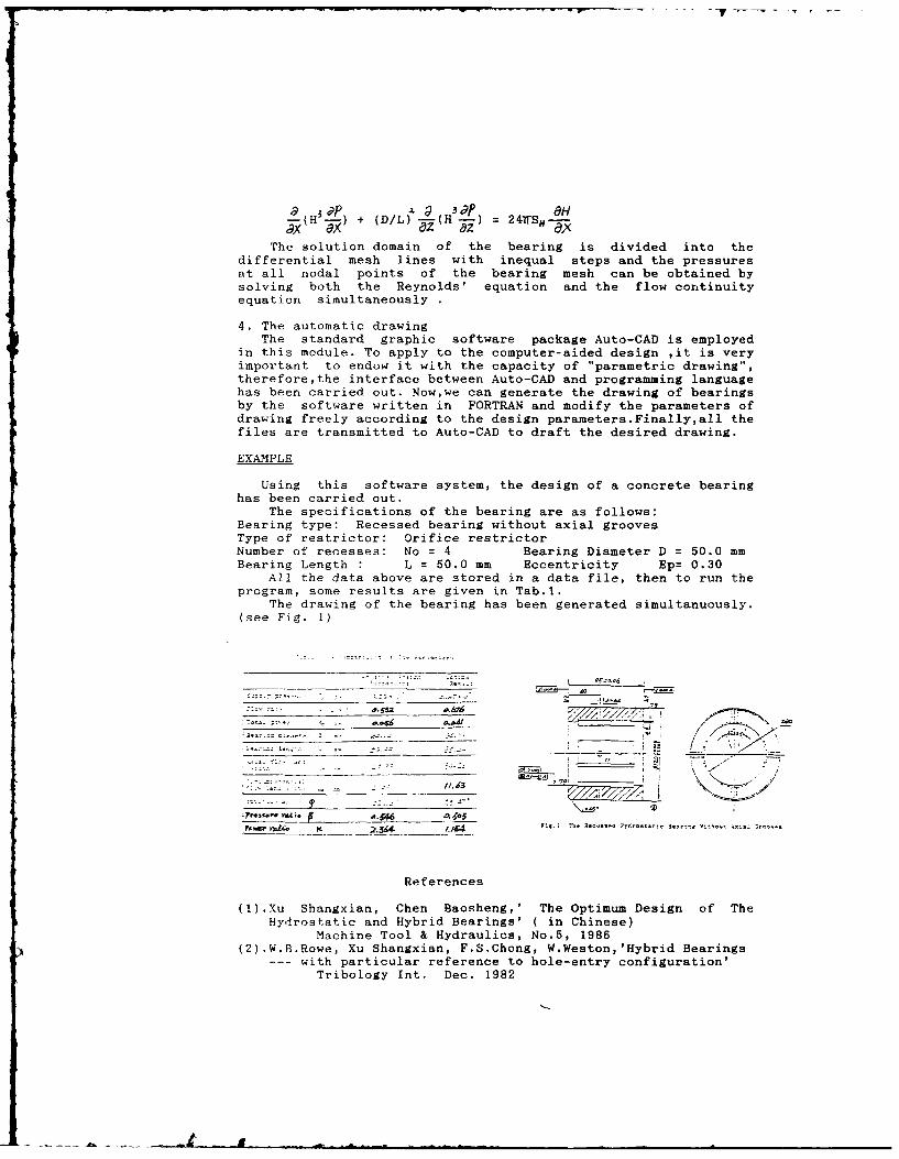
-(H -7) + (D/L)--(H3 2) MrT~x ax 82 az'
The solution domain of the bearing is divided into thedifferential mesh lines with inequal steps and the pressuresat all nodal points of the bearing mesh can be obtained bysolving both the Reynolds' equation and the flow continuityequation simultaneously
4. The automatic drawingThe standard graphic software package Auto-CAD is employed
in this module. To apply to the computer-aided design ,it is veryimportant to endow it with the capacity of "parametric drawing",therefore,the interface between Auto-CAD and programming languagehas been carried out. Now,we can generate the drawing of bearingsby the software written in FORTRAN and modify the parameters ofdrawing freely according to the design parameters.Finally,all thefiles are transmitted to Auto-CAD to draft the desired drawing.
EXAMPLE
Using this software system, the design of a concrete bearinghas been carried out.
The specifications of the bearing are as follows:Bearing type: Recessed bearing without axial groovesType of restrictor: Orifice restrictorNumber of recesses: No = 4 Bearing Diameter D = 50.0 mmBearing Length : L = 50.0 mm Eccentricity Ep= 0.30
All the data above are stored in a data file, then to run theprogram, some results are given in Tab.l.
The drawing of the bearing has been generated simultanuously.(see Fig. 1)
References
(1).Xu Shangxian, Chen Baosheng,' The Optimum Design of TheHydrostatic and Hybrid Bearings' (in Chinese)
Machine Tool & Hydraulics, No.5, 1986(2).W.B.Rowe, Xu Shangxian, F.S.Chong, W.Weston,'Hybrid Bearings
--- with particular reference to hole-entry configuration'
Tribology Int. Dec. 1982
tg.
SESSION XIV (Paper (ii) - FRIDAY 9th SEPTEMBER
COMPUTER AIDED DESIGN OF EXTERNALLY PRESSURIZED BEARINGS
by
G J J van Heijningen and C M Kalker-Kalkman
(Delft University of Technology, The Netherlands)
SYNOPSIS
The selection and calculation of suitable bearings for a given mechanicalapplication is a significant problem for a mechanical engineer. He meets thedifficulty to compare different types of bearings and to make the bestchoice for his problem out of the most promising types. The designer wouldneed to be an expert on all competing types to make a meaningful comparison.Such levels of knowledge are rare amongst specialists. There is, however,scope for making the necessary information available via a computer, whichin effect acts as the expert and operates in an interactive consultationmode.
A research programme has been instigated at the- Delft University ofTechnology which aims to introduce such a computer-aided technique into thebearing selection process. As a first stage of the development the bearingtype: "externally pressurized bearing" is chosen.We managed to reduce the selection criteria down to 8 basic factors depend-ing on what kind of design function is involved. When all data describing anapplication have been used as input to the system, the desired propertiesare compared with those in a databasesystem.The proposed bearingtype is not only presented by its name but also by asimple drawing on a second screen. If the designer is satisfied with theproposed bearing the remaining general properties of the chosen bearing arecollected from the database. Further output includes the detailed analysisof specific properties by means of a spreadsheet program.
Expert knowledge for other bearing types might be implemented using the samesystem architecture.
SESSION XIV (Paper (iii)) - FRIDAY 9th SEPTEMBER
A THEORETICAL INVESTIGATION OF HYBRID JOURNAL BEARINGS
APPLIED TO HIGH SPEED HEAVILY LOADED CONDITIONS
REQUIRING JACKING CAPABILITIES
by
D Ives, (Liverpool Polytechnic, U K)W Weston (Huddersfield Polytechnic, U K)
P G Morton (GEC Engineering Research Centre, Stafford, U K)W B Rowe (Liverpool Polytechnic, U K)
SYNOPSIS
This paper presents the results of a theoretical investigation of acommonly used generator bearing geometry and an alternative slot entry
configuration. The work attempts to show the improvements in performancethat are possible by paying particular attention to the type and position-ing of the high pressure jacking sources within the bearing. The workalso shows that optimisation using laminar or superlaminar theory producesthe same optimum bearing geometry.
Theory
A dimensionless form of the Reynolds equation capable of accountingfor superlaminar flow was used in the analysis.
2,I+I-I+ - = 21TS h - +S
TX k aX Sh~d a~~Jhxx z
The terms kx, kz were used to take account of turbulence effects and werederived from the work of Elrod and Ng [1]. The term S is a source termfor the slot entry bearing. The transition region between laminar and fully
developed turbulen flow was accounted for using the techniques developed by
Constantinescu et al [2].
Comparisons between bearing types were conducted using load/total
power and a coefficiert of merit scheme. [3].
Results
Optimisation studies conducted for both laminar and superlaminar theory
showed that the load capacity of conventional generator bearings could be
enhanced by correct positioning of the jacking pockets. Further improvements
in load capacity were possible by adopting the slot entry configuration(fig.1). As a result of these increases in load capacity. it was shown
that reductions in power consumption were possible.
The optimisation studies also showed that the optimum geometry
indicated by superlaminar theory was identical to that indicated by laminartheory.
-.. 1 _ ,,.i a akmW Il m is
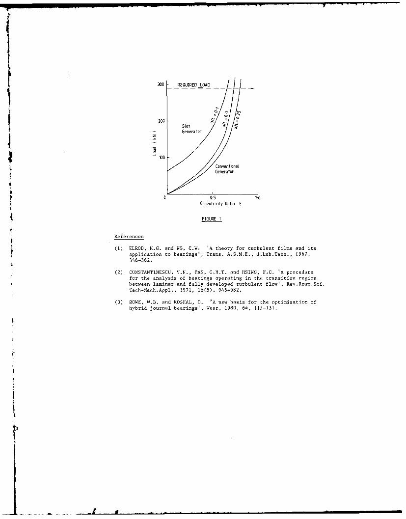
300 REQUIRED LOAD
2002- '4
io
Eccntrcy RaoE
Slot
nenerator
(1) Conventional5Generator
0o0s 1.0iEccentricity Ratio E
~FIGURE 1
~References
(1) ELROD, H.G. and NG, C.W. 'A theory for turbulent films and its
application to bearings', Trans. A.S.M.E., J.Lub.Tech., 1967,346-362.
(2) CONSTANTINESCU, V.N., PAN, C.H.T. and HSING, F.C. 'A procedure
for the analysis of bearings operating in the transition region
between laminar and fully developed turbulent flow', Rev.Roum.Sci.Tech-Mech.Appl., 1971, 16(5), 945-982.
(3) ROWE, W.B. and KOSHAL, D. 'A new basis for the optimisation of
hybrid journal bearings', Wear, 1980, 64, 115-131.
t"
tl
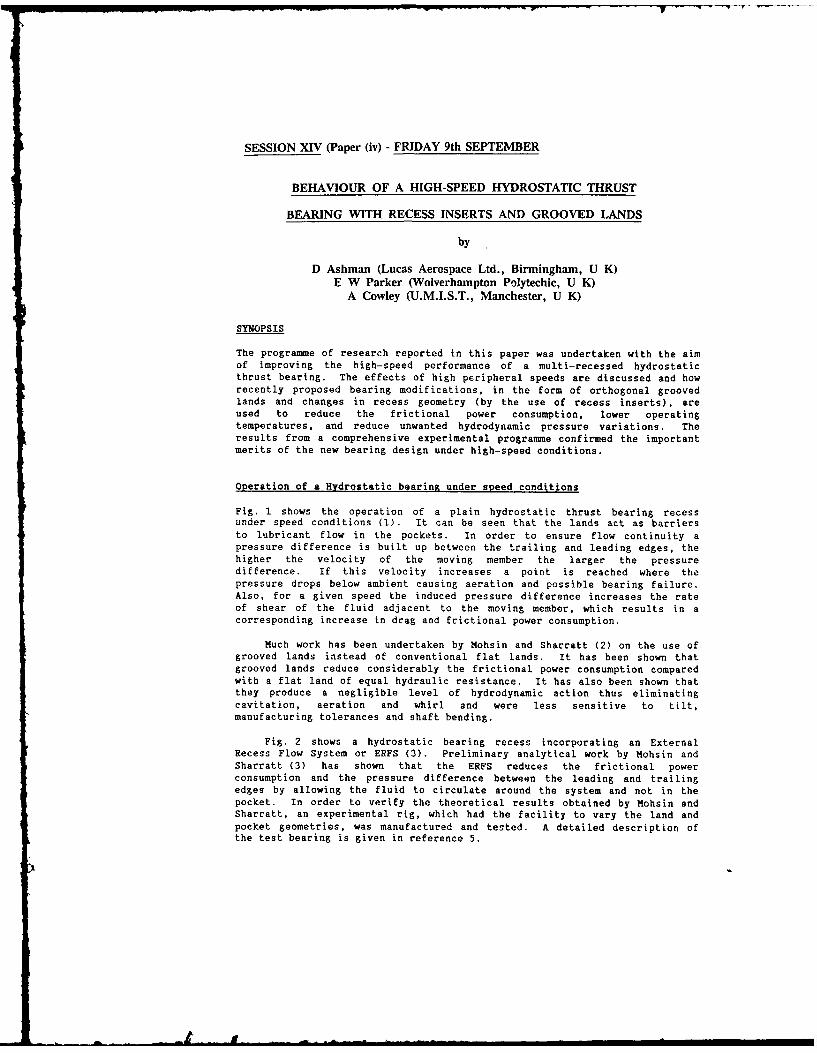
SESSION XIV (Paper (iv) - FRIDAY 9th SEPTEMBER
BEHAVIOUR OF A HIGH-SPEED HYDROSTATIC THRUST
BEARING WITH RECESS INSERTS AND GROOVED LANDS
by
D Ashman (Lucas Aerospace Ltd., Birmingham, U K)E W Parker (Wolverhampton Polytechic, U K)
A Cowley (U.M.I.S.T., Manchester, U K)
SYNOPSIS
The programme of research reported in this paper was undertaken with the aimof improving the high-speed performance of a multi-recessed hydrostaticthrust bearing. The effects of high peripheral speeds are discussed and howrecently proposed bearing modifications, in the form of orthogonal groovedlands and changes in recess geometry (by the use of recess inserts), areused to reduce the frictional power consumption, lower operatingtemperatures, and reduce unwanted hydrodynamic pressure variations. Theresults from a comprehensive experimental programme confirmed the importantmerits of the new bearing design under high-speed conditions.
Operation of a Hydrostatic bearing under speed conditions
Fig. 1 shows the operation of a plain hydrostatic thrust bearing recessunder speed conditions (1). It can be seen that the lands act as barriersto lubricant flow in the pockets. In order to ensure flow continuity apressure difference is built up between the trailing and leading edges, thehigher the velocity of the moving member the larger the pressuredifference. If this velocity increases a point is reached where thepressure drops below ambient causing aeration and possible bearing failure.Also, for a given speed the induced pressure difference increases the rateof shear of the fluid adjacent to the moving member, which results in acorresponding increase in drag and frictional power consumption.
Much work has been undertaken by Mohsin and Sharratt (2) on the use ofgrooved lands instead of conventional flat lands. It has been shown thatgrooved lands reduce considerably the frictional power consumption comparedwith a flat land of equal hydraulic resistance. It has also been shown thatthey produce a negligible level of hydrodynamic action thus eliminatingcavitation, aeration and whirl and were less sensitive to tilt,manufacturing tolerances and shaft bending.
Fig. 2 shows a hydrostatic bearing recess incorporating an ExternalRecess Flow System or ERFS (3). Preliminary analytical work by Mohsin andSharratt (3) has shown that the ERFS reduces the frictional powerconsumption and the pressure difference between the leading and trailingedges by allowing the fluid to circulate around the system and not in thepocket. In order to verify the theoretical results obtained by Mohsin andSharratt, an experimental rig, which had the facility to vary the land andpocket geometries, was manufactured and tested. A detailed description ofthe test bearing is given in reference 5.
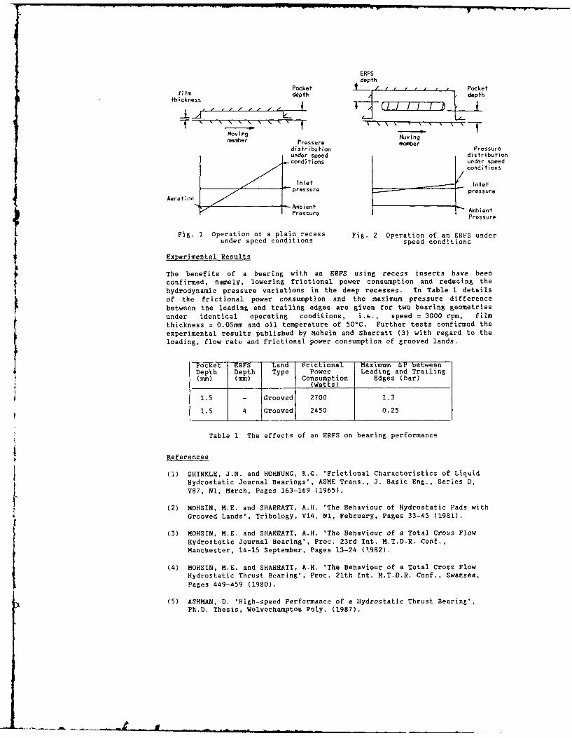
ERFSdepth
Pocket I' ' ' Pocketfi Im depth depth
thickness
S"''''' '''-f- "'" ' -"
moving Movingmember Pressure member
distribution Pressureunder speed distributionconditions under speed
conditions
Inlet InletAt pressure pressure
Aer at i onAmin
PrssreAbientenPressure Pressure
Fig. 1 Operation of a plain recess Fig. 2 Operation of an ERFS under
under speed conditions speed conditions
Experimental Results
The benefits of a bearing with an ERFS using recess inserts have beenconfirmed, namely, lowering frictional power consumption and reducing thehydrodynamic pressure variations in the deep recesses. In Table 1 detailsof the frictional power consumption and the maximum pressure differencebetween the leading and trailing edges are given for two bearing geometriesunder identical operating conditions, i.e., speed = 3000 rpm, filmthickness = 0.05mm and oil temperature of 50°C. Further tests confirmed theexperimental results published by Mohsin and Sharratt (3) with regard to theloading, flow rate and frictional power consumption of grooved lands.
Pocket ERFS Land Frictional Maximum &P betweenDepth Depth Type Power Leading and Trailing(mm) (mm) Consumption Edges (bar)
(Watts)
1.5 - Grooved 2700 1.3
1.5 4 Grooved 2450 0.25
Table 1 The effects of an ERFS on bearing performance
References
(1) SHINKLE, J.N. and HORNUNG, K.G. 'Frictional Characteristics of LiquidHydrostatic Journal Bearings', ASME Trans., J. Basic Eng., Series D,V87, Nl, March, Pages 163-169 (1965).
(2) MOHSIN, M.E. and SHARRATT, A.H. 'The Behaviour of Hydrostatic Pads withGrooved Lands', Tribology, V14, Nl, February, Pages 33-45 (1981).
(3) MOHSIN, M.E. and SHARRATT, A.H. 'The Behaviour of a Total Cross FlowHydrostatic Journal Bearing', Proc. 23rd Int. M.T.D.R. Conf.,Manchester, 14-15 September, Pages 13-24 ('982).
(4) MOHSIN, M.E. and SHARRATT, A.H. 'The Behaviour of a Total Cross FlowHydrostatic Thrust Bearing', Proc. 21th Int. M.T.D.R. Conf., Swansea,Pages 449-459 (1980).
(5) ASHMAN, D. 'High-speed Performance of a Hydrostatic Thrust Bearing',Ph.D. Thesis, Wolverhampton Poly. (1987).

SESSION XV - (Paper (i)) - FRIDAY 9th SEPTEMBER
TRIBOLOGICAL DESIGN - INFORMATION STORAGE AND RETRIEVAL
by
B Bhushan
(IBM Research Division San Jose U S A)
This paper presents the status of our current understanding of the tribology of head-medium interfaces in magnetic storagedevices. To start out, designs and materials used in the construction of heads and media for tape, floppy, and rigid diskdrives are presented. Theories of conventional friction, stiction, interface temperatures, wear, liquid/solid lubrication, andcompressible hydrodynamic lubrication relevant to magnetic media are presented. Whenever necessary, experimental dataare presented.
1.0 INTRODUCTION forming the air bearing surface and a magnetic : .ng corecarrying the wound coil with a read-write gap. In the film
Magnetic recording process is accomplished by relative heads, the core and coils or MR stripes are deposited bymotion between magnetic media against a stationary thin-film technology. The air-bearing surfaces of most(audio and data processing) or rotating (video) read/write heads are made of hard ceramic materials - Ni-Zn ferrite,magnetic head. Under steady operating conditions, a load Mn-Zn ferrite, calcium titanate, and Al2O-TiC (Klaus andcarrying air fdm is formed. There is a physical contact Bhushan. 1985).between the media and the head during starting and Schematic of head-medium interfaces for tape,stopping. In modem high-end computer tape and rigid floppy, and rigid disk drives are shown in Fig. I.disk drives, the head-to-media separation ranges fromabout 0.1 to 0.4 pm. In floppy disk drives, head-to-mediaseparation is even less (<0.2 gm) and physical contactgenerally occurs (Bhushan. 1989).
Need for higher and higher recording densitiesrequires that surfaces be as smooth as possible and flyingheights be as low as possible. Smoother surfaces lead toan increase in friction and interface temperatures andcloser flying heights lead to occasional rubbing of highasperities and increased wear. Since interface faiure evenon a microscopic scale can lead to loss of valuablemagnetic data recorded on a media, high interfacereliability through the life of a magnetic storage becomesextremely important. A fundamental understanding of thetribology of magnetic storage systems is. therefore, crucialfor the continued growth of the magnetic storage industry.
This paper presents the status of our understandingof tribology of head-medium interfaces.
2.0 MAGNETIC STORAGE DEVICES
Magnetic storage systems used for information storage andretrieval are: tape, floppy disk, and rigid disk drives.Magnetic media fall into two categories: particulate
media, where magnettc particles are dispersed in apolymeric matrix and coated onto the polymeric substrateFor flexable media (tape and floppy disks) or onto the rigidsubstrate typically aluminum) for rigid disks; thin-filmmedia. where continuous films of magnetic material aredeposited onto the substratc by vacuum techniques.
Typical matenials used for various magnetic media andoperating conditions in computer applications are shown-i faie I (Klaus and 13husnan. 1985).
Magnetic hcads ascJ to date arc either conventionalinducuis or thin-fim inductive and magncrtorcisti r XI RIheads. Cons entions hr.,k are cnvthtn:itinn i' a hod%
SESSION XV (Paper (iii) - FRIDAY 9th SEPTEMBER
ACTIVE MAGNETIC BEARING DESIGN METHODOLOGY -
A CONVENTIONAL ROTORDYNAMICS APPROACH
by
H Ming Chen
(Mechanical Technology Inc., New York U S A)
Synopsis
The recent advance of Active Magnetic Bearing (AMB) technology opens a newchallenge to rotor-bearing design methodology.(1) Although rotor-bearingdesign is a well developed field in mechanical engineering, these new bearingsinvolve eiectromagnetics and system control, areas which traditionally falloutside the rotor-bearing field. Mathematical modeling of AMBs is generallyperformed in electrical engineering and control language, in which the mechan-ical engineer is less fluent. To bridge the communication gap, the authorpromotes the features of the AMB from a rotor dynamist's point of view: (a) TheAMB should be treated as a locally controlled device similar to other types ofbearings, not actuators. (b) Like other bearings, the main functions of the AMBare to provide load capacity, stiffness and damping for supporting rotors.(2)Specific AMB characteristics are described below:
A radial AMB consists of four quadrants of north-south poles (seeFig. I). Each pair of opposite quadrants is stabilized independently bycurrent control - similar to controlling a vertical rod at its base.- AMB size is dictated by the saturation flux density of the ferromag-
netic material. More stator poles can save radial space.- The current slew rate, coil inductance and bias current of the poweramplifiers/electromagnets limit the AMB frequency response and cancause instability in high frequency range.
- A PID controller with three adjustable parallel circuit elements isused to achieve desired static and dynamic stiffnesses and damping.Only the journal displacement is measured. Analog circuit elements,
such as the differentiator, phase-lead network or Velocity Observercan be used in the controller to obtain a pseudo velocity for generat-ing damping.
The AMB dynamics are represented by a set of first-order differentialequations (see Fig. 2). The conventional rotor model state vector is
extended to include the AMB states; thus an electromechanical dynamicmodel is formed for rigorous stability and unbalance response analyses.The control guidelines for rotor bending modes are described through useof an example. Bending modes below the operating speed must be welldamped. The next one should be 15 to 20% in frequency above the operat-ing speed and reasonably damped. Other unstable, high frequency modes,if they exist, can be detuned using band-reject filters implanted in thefeedback control loop.
Because this presentation of AMBs uses a technical language that is more
acceptable to mechanical engineers, it can accelerate the development of AMB
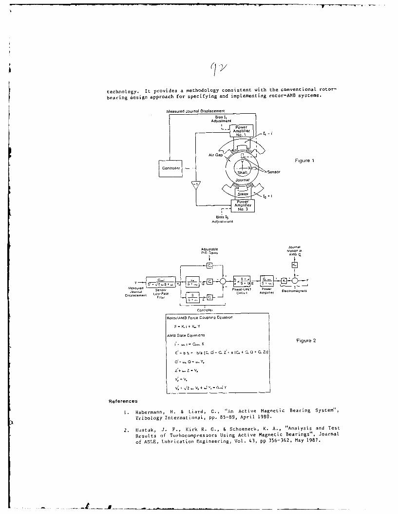
technology. It provides a methodology consistent with the conventional rotor-
bearing design approach for specifying and implementing rotor-AB systems.
Measured Journal Displacement
Bias I,Adjustment
PowerAmplifier
No. I
Air Gap
Y Figure 1
lAmplifier
r -No.___Bias 13
ljournalAID uGabne Motion at
PlO a~nsANIB r.
-t_
sp , aceSe Lo-as Y~l , i__bE
Measure I " . .. ..
nt wPAmplifier
Placenta~Bia 13 sS ic,
I(
Controller
Aolor/AMB Force Coupling Equation
F = K i + K. Y
AMB State Equations
i' i,. = G.,. E Figure 2
E' + b E = -b/a iC. d+ C. Z+ a (C. + C. 0 + C. Z)i
d+ .. 0 .. Y,
Z'+ .. z = v .
', = V,
V; + /2 V, + .. -G - ', Y
References
1. Habermann, H. & Liard, G., "An Active Magnetic Bearing System",
Tribology International, pp. 85-89, April 1980.
2. Hustak, J. F., Kirk R. C., & Schoeneck, K. A., "Analysis and Test
Results of Turbocompressors Using Active Magnetic Bearings", Journal
of ASLE, Lubrication Engineering, Vol. 43, pp 356-362, May 1987.
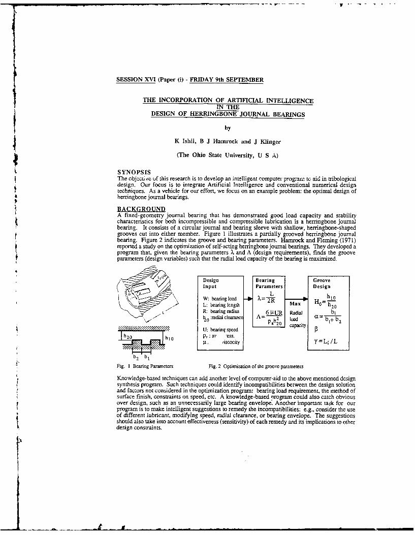
SESSION XVI (Paper (i) - FRIDAY 9th SEPTEMBER
THE INCORPORATION OF ARTIFICIAL INTELLIGENCEIN THE
DESIGN OF HERRINGBONE JOURNAL BEARINGS
byJK Ishii, B J Hamrock and J Klinger
(The Ohio State University, U S A)
L SYNOPSISThe objcctuvc f this research is to develop an intelligent computer program to aid in tribologicaldesign. Our focus is to integrate Artificial Intelligence and conventional numerical designtechniques. As a vehicle for our effort, we focus on an example problem: the optimal design of
4t herringbone journal bearings.
BACKGROUNDA fixed-geometry journal bearing that has demonstrated good load capacity and stabilitycharacteristics for both incompressible and compressible lubrication is a herringbone journalbearing. It consists of a circular journal and bearing sleeve with shallow, herringbone-shapedgrooves cut into either member. Figure 1 illustrates a partially grooved herringbone journalbearing. Figure 2 indicates the groove and bearing parameters. Hamrock and Fleming (1971)reported a study on the optimization of self-acting herringbone journal bearings. They developed aprogram that, given the bearing parameters X and A (design requirements), finds the grooveparameters (design variables) such that the radial load capacity of the bearing is maximized.
Ll12 Design Bearing GrooveInput Parameters Design
W: bearing load h1oL: bearing length Max HO h 20
L R: bearing radius 6 ILuR Radial bl'10 :radial clearance A- l a0 a a 1+ b2
U: bearing speed,. hto p, : ar "ess.
9. Aiscocity
b2 b1
Fig. 1 Bearing Parameters Fig. 2 Optimization of the groove parameters
Knowledge-based techniques can add another level of computer-aid to the above mentioned designsynthesis program. Such techniques could identify incompatibilities between the design solutionand factors not considered in the optimization program: bearing load requirement, the method ofsurface finish, constraints on speed, etc. A knowledge-based program could also catch obviousover design, such as an unnecessarily large bearing envelope. Another important task for ourprogram is to make intelligent suggestions to remedy the incompatibilities: e.g., consider the useof different lubricant, modifying speed, radial clearance, or bearing envelope. The suggestionsshould also take into account effectiveness (sensitivity) of each remedy and its implications to otherdesign constraints.
Ishii and Barkan (1987) developed a framework for knowledge-based design called DesignCompatibility Analysis (DCA) that accommodates the features described above. DCA focuses onthe compatibility, both qualitative and quantitative, between design requirements and designsolutions (Fig. 3). DCA matches a given requirement and solution with compatibility knowledge(good and bad templates of design), combines the matching compatibility knowledge, and gives atotal evaluation. In addition, DCA provides justifications for the evaluation and suggestion forimprovement that applies not only to the design solution, but also to the design specificaton.
CURRENT WORKThis paper reports the use of DCA as a knowledge-based design loop that applies to theoptimization program developed by Hanrock and Fleming (1977). Fig. 4 shows the flow of thedesign process which uses the numerical optimization as an inner design loop and DCA as an outerloop. The user of the program first enters the design requirements: bearing envelope (L and R),lubricant viscosity li, bearing speed U, radial clearance h20, and the bearing load W. Theoptimization program calculates the value of the groove parameters, H0, c, 13, Y, i.e., for thedesign solution. Then, DCA asks additional questions (e.g., surface finish) and evaluates thecompatibility of the design solution. If the design solution is unacceptable or is obviously an overdesign, the user can seek suggestions from DCA. DCA could suggest changes in bearingenvelope, the lubricant, bearing speed, or radial clearance. The overall program helps thedesigners to consider manufacturing concerns in their design and thus helps them make a tradeoffbetween performance and cost.
Some specific performance checks that are made for each consideration are:1) suitability of a hydrodynamic bearing2) safe minimum film thickness
3) adequacy of load capacity and stiffness4) effect of shaft angular deflection and assembly misalignment on h20 at the edge of bearing5) transition speed between laminar and Taylor vortex flow6) self-excited whirl instability ratio7) flow rate, power loss, and attitude angle.
Specification/ Respecify Design
Requirement RequirementsI Requirement
IT
I
oldeEvaluation Groove Mdfcto
CopModificatioy
Suggestion DCA uggestionAnalytical Evaluation~ ~~~~~~Model
E auainIt
Proposed I eI
Design Redesign
Fig. 3 Schematics of DCA Fig. 4 Fow of intelligent bearing design
We implemented both the numerical and Al programs on an IBM PC. The program usesTurbo-PROLOG for DCA and FORTRAN for numerical optimization. The overall programgenerates an executable object file which the users can run without compilers or loaders.
In summary, this paper shows an example of how one can combine numerical techniques andAl-based methods to aid in the design of herringbone bearings. We hope to extend ourmethodology to other tribological design examples.
REFERENCESHamrock, B.J. and Fleming, D.P. (1971) Optimization of Self-acting Herringbone Journal
Bearings for Maximum Radial Load Capacity. NASA Technical Note, NASA TN D-635 1.Ishii. K. and Barkan. P. (1987) Design Compatibility Analysis--a framework for expert systems
in mechanical design. ASME Computers in Engineering 1987. Vol. one, pp.95-102.

SESSION XVI (Paper (ii)) - FRIDAY 9th SEPTEMBER
BEARING SELECTION USING A KNOWLEDGE BASED SYSTEM
by
R T Griffin, M J Winfield (Birmingham Polytechnic, U K)
S S Douglas (Liverpool Polytechnic, U K)
SYNOPSIS
It is recognised that there is a considerable difference in thelevels of tribological knowledge typically found in academia andother research establishments compared to that frequently
encountered in industry. If this difference is to be addressed,technology transfer mechanisms need to be developed, which can actas a conduit through which knowledge can flow. One technologytransfer mechanism currently receiving wide attention is thedevelopment of tribological databases.
This paper reports upon a different technology transferstrategy which utilises knowledge based systems. These systemsdiffer from a database approach in that they cimprise both aknowledge base coupled with a search mechanism. These two componentsinteract with the user to establish a solution to a specificproblem, using the expert knowledge represented within the system.Two prototype systems have been developed to illustrate technologytransfer for the selection of rotary rolling-element bearings. In
particular the practicalities of acquiring knowledge and itssubsequent representation within a system are discussed.
A block diagram representing the major stages of the systemoperation is shown in figure 1:
1) FORM FILLING SESSION - data is interactively entered intothe system at the beginning of a session by filling in forms. Onceentered, data is checked against a set of constraints. If any dataitems conflict, the system reports them to the user and requests theuser to alter one of the conflicting data items.
2) PROBLEM SOLVING SESSION - whilst attempting to derive asolution, the knowledge base rules and database components aresearched for appropriate items of knowledge/data. When the systemcannot find an appropriate item of data, an interactive question isgenerated for the user to answer. Once entered, data is againchecked against a set of constraints.
3) SOLUTION REPORTING SESSION - any solutions found during theproblem solving session are displayed to the user. An examplesolution determined by the system for a given set of data is shownin figure 2. The solution is for a two location bearing arrangementin which one bearing is to be used at each location. The bearingtypes are to be single .,ow deep groove ball and a database searchhas established six feasible components to use.
"" '" ----- ---- -- .=..,L---.,,1
Data: appliationdgmairateE
S FORM FILLING SESSION t
en~tmpchngsnegligiblerat
DATABASE e iQUESTION
yes USER
4 ANOTHER SOLUTIN]
r< e ANOTHER SESON.
Figure 1 -Block diagram representation of system operation.
Data: application-domain = OTHERenv_tempchanges_negligibledist_ fixed free negligible
angular misalignment required = verysmalldegreeof rigidity required = verylow
appliedradialload_magnitudefixed end= 3 kNappliedradial load magnitude_free end = 2 kNappliedaxialload_magnitude = 2 kNshaftdiameter_max = 500 mmshaftdiametermin = 258 mmhousing_bore_diameter max = 600 mmhousingbore_diameter min = 510 mmsnap ring type = withoutprotection = none
rotationalspeed = 750 rpmenvironmentaltemperature max = 50 Ctime or revs life = revs
revs-life = 6 million revs
SOLUTION: ARRANGEMENT : fixed end = free endBEARING TYPE : single_row_deep grooveballFEASIBLE COMPONENT NUMBERS : 6068, 6072, 6976,
6076, 6980, 6080
Figure 2 - Solution determined by system using given set of data.
. .. . .. _ _ : . .. . k- N m = = . . . . . , - , m m m m m m m m m m m m m
SESSION XVI - (Paper (iii)) - FRIDAY 9th SEPTEMBER
TRIBOLOGY AIDS FOR DESIGNERS
by
C J Thijsse
(Philips Centre for Manufacturing Technology, The Netherlands)
SYNOPSIS
During the design phase of a construction, tribology is only one aspect that must be
considered. The designer's tribological knowledge consists of single, more or less reliablefacts. It therefore follows that it takes the designer a great deal of time to incorporatetribological aspects into his design, assuming he knows where to find these more or lessestablished facts. What is needed is a logical collation of this knowledge. It is important tobe able to assess whether a given design will encounter tribological problems by using somerules-of-thumb or simple computer programs. Insight into the tribological properties thatplay a part also need to be given, and ways must be indicated, along which solutions can befound.
For these reasons, we have divided tribology into four parts; construction, lubricant,(surface) material and environment.
Design specifications concerning dynamic and static behaviour, namely force, kind ofmotion, shape and permitted wear height, are reflected in the design.
The building blocks are formed by:
a) the lubricant with viscosity and boundary lubrication properties as the importantparameters and
b) the (surface) materials with the important parameters of elasticity, hardness androughness.
The environment forms the constraints within which the tribological system has to work.
We can now define the problem to be solved as follows: "What kind of building blocksshould be chosen to meet the design specifications within the given environmentalconstraints?"
Plastic deformation, too much wear height and surface fatigue are considered as failurecriteria.
-s-
To establish whether plastic deformation will occur in the contact, the admissible stress iscompared with the actual stress. For counterformal situations, the contact stress iscalculated according to Hertz. We have developed a computer program to calculate easilyother contact situations than ball-ball or parallel cylindrical contact. Any necessarycorrections can be made when a traction force is present.
To check that the admissible wear height is not exceeded, we compare the admissible wearfactor (k-value) with the expected wear factor. Given the admissible wear height, the modeof motion of the surfaces relative to each other and of the contact place relative to thesurfaces, the contact force and the shape of the contacting parts, one can easily calculatethe admissible wear factor according to Archard, using a small computer program. Forcounterformal contacts, we have developed a computer program based on the work ofDowson and Higginson to calculate the situation of lubrication. Quick estimations for theexpected wear factor can be made using a graph showing roughly the wear factors in relationto several tribo systems. For a more accurate prediction of the actual wear factor, we havebuilt a database containing wear and friction results of approximately 600 series of (mainlypin-disc and pin-ring) experiments carried out in our own laboratory under varyingcircumstances. We are also building a similar system containing data from literature.
Plastic-metal systems can be tested for the permissible pv-value or pt-value, using acomputer program based on the formulae from Erhard and Strickle.
Using data from literature, we have formed empirical formulae to establish whether thereis a danger of surface fatigue. These formulae give, for metal surfaces, the relation betweenthe contact stress, the number of load cycles during service lifetime, the situation oflubrication and the hardness of the material.
The above-mentioned formulae, graphs and PC programs give quick and easy insight intothe feasibility of simple tribo systems. Also, to make the more complicated systemsmanageable, we have built a prototype expert system based on the tools mentioned,together with approximately 200 tribological rules(-of-thumb).
It should be clear from this approach that tribological expertise must not only be structured,but also simplified; indeed, this seems to be the only way for large groups of designers tolearn about tribology. We hope to eliminate most of the trivial wear problems in this manner- in the event of very special tribological problems, the tribology experts are always willingto help.
15th LEEDS-LYON SYMPOSIUM ON TRIBOLOGY
THE TRIBOLOGICAL DESIGN OF MACHINE ELEMENTS
6th - 9th SEPTEMBER 1988
ACCOMMODATION
All delegates will be housed at Bodington Hall, a University of Leeds Hall of
Residence, where technical sessions will also be held. The enclosed FACT SHEET will
help delegates locate Bodington Hall - those arriving by air at Leeds/Bradford Airport
should note that it is more convenient to take a taxi to the Hall than to use public
transportation.
REGISTRA TION
This will take place at Bodington Hall on the afternoon of Tuesday 6th September.
commencing at 14.00. The Symposium registration desk will be located in the main
entrance foyer at Bodington Hall and clear directions will be given on the precinct.
FIRST TECHNICAL SESSION
The Symposium Opening and Keynote Lecture to be presented by PROFESSOR H.S. CHENG will
commence at 17.30 on the 6th September. Immediately afterwards at about 18.30 buses
will leave Bodington Hall to take delegates to the Symposium Dinner to be held at the
MERCHANT ADVENTURERS HALL, YORK.
DEPARTURE
Luggage may be left in the gym (see FACT SHEET) on the day of vacating. It would be
appreciated if rooms could be cleared as soon as possible. We are able to arrange
accommodation for those requiring it on the Friday night and indeed on Monday 5th
September the day immediately preceding the Sy'nposium.
SYMPOSIUM TELEPHONE NUMBER: (Leeds ((.j, , 70756).
OHER DETAILS
There are some amendments to the provisional technical programme already distributed
and details are enclosed. The final programme. together with the synopses of the
papers and other material, will be available to delegates on registration. For any
other information please telephone Leeds (0532) 332155.
We look forward to welcoming you to Leeds and to a fruitful and enjoyable Symposium.
D. DOWSON
C.M. TAYLOR
August, 1988
CONFERENCE FACILITIES
The University of FACT SHEET
LeedsConference Organiser'sOffice/RegistrationThe entrance lobby features aconference registration desk, porter'slodge and conference organiser'soffice for use throughout each event.Equiped with desk, externaltelephone line, etc., this facilityprovides the convenience of efficientcommunications on arrival andthroughout each event.
Car ParkingPlentiful free car-parking is availablethroughout the extensive grounds.
AccommodationUp to 700 guests can be accommodatedin comfortable study bedrooms, themajority of which are singleoccupancy with a small number oftwin rooms also available. Wash-handbasins are provided within 300 of theguest bedrooms, and each residentialblock contains a common roomlloungc
and a launderette. Each group of rooms shares akitchen equipped with tea/coffee makingfacilities for visitors' use.N.B. Residential accommodation is availableonly during vacation periods-normallyJuly/August/September, End December/Early
Standing in 14 acres of private grounds in the attractive Leeds January, End March/April.suburb of Arel, the Halfis a modern purpose-built Audio Visual Equipmentconference and residential complex. Situated adjacent to theLeeds Outer Ring Road, an important advantage is the quick The Hall provides a number of items ofand easy access to all major incoming routes leading from the equipment free of charge for conference events,national motorway network and the close proximity of the including:-international Leeds/Bradford Airport. Rostrum and LecternPA System (Including Radio-Link Microphone)With the capacity to accommodate a maximum of 700 Roll-Down Projection Screensvisitors, the Hall offers in-house facilities for self-contained Flp-Charts and Blackboardsconferences, seminars and sfecial events for up to 300 Flp and Blackb orsdelegates. OHP and 35mam. Carousel Projectors
Additional equipment can be hired in fromThe central building provides all conference rooms, dining specialist outside suppliers on request.hall, sports and recreational areas. Close by lie eight houses,each with 75/80 bedrooms. The Hall overlooks a large Receptionsexpanse of lawned gardens and playing fields offering a wide Private receptions, smaller dinners, etc. can berange of opportunities for sporting tournaments, displays, rate wtin Small Dinng etodemostrtios an siila outoorevetsarranged within the Small Dining Room todemonstrations and similar outdoor events. provide a less formal atmosphere for up to
100 visitors.
DAY SEMINARS-THROUGHOUT THE YEAR organisation of this type of event, and our specialThe excellent location, wide range of meeting rooms and Day Seminar package includes room hire chargesconvenient layout of the Hall make it particularly suited for a (including syndicate rooms), audio-visualone-day conference/seminar. This facility is available for up equipment, set conference lunch and refreshmentsto 300 delegates and may be used throughout the year, between sessions.including week-days during term time. Day seminar package currently charged at.................The Management and Staff have a wealth of experience in the per person per day, plus VAT at the appropriate rate.
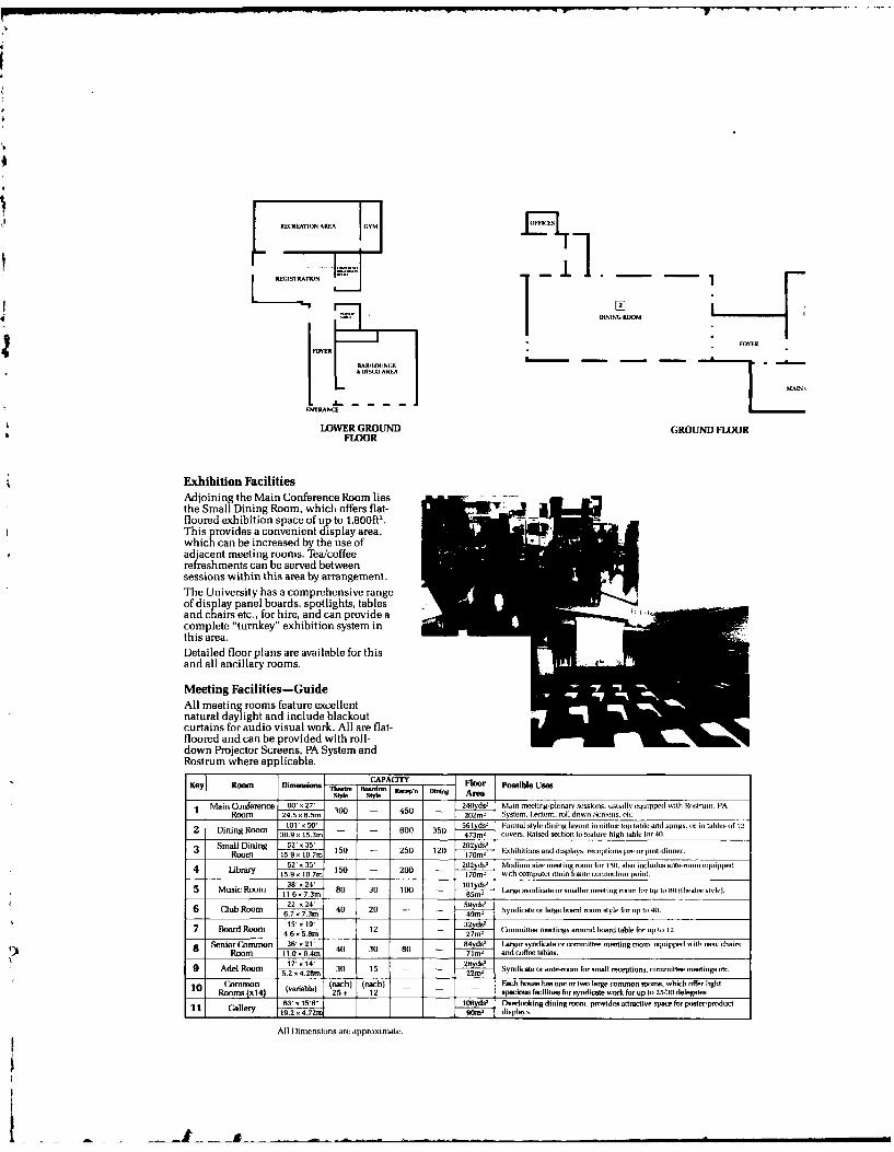
REREATION AREA GYM
RGSOTON H
DINING ROOM
ENTRANCE
£LOWER GROUND GROUND FLOORFLOOR
Exhibition FacilitiesAdjoining the Main Conference Room liesthe Small Dining Room, which offers flat-floored exhibition space of up to i,800ft'.This rov ides a convenient display area,whicIE can be increased by the use ofadjacent meeting rooms. Tea/coffeerefreshments can be served betweensessions within this area by arrangement.The University has a comprehensive rangeof display panel boards, spotlights, tablesand chairs etc., for hire, and can pruvide acomplete "turnkey" exhibition system inthis area.Detailed floor plans are available for thisand all ancillary rooms.
Meeting Facilities-GuideAll meeting rooms feature excellentnatural daylight and include blackoutcurtains for audio visual work. All are flat-floored and can be provided with roll-down Projector Screens, PA System andRostrum where applicable.
Key ~ ~ __ -om Dmnios CP~ Floor possible Uses
sty[e Style _____ Are._________________
Main Conference 80O 270 1) 45 - 240yds! Main mIeeling/llllena nssiIons. Iuriallveqlippell will, Rstroo. PARoom 24.50 x .5m0 5 202meV System. I-ecn, roil down, Sce-, et,:.
2 iigRoom -01 xo 550 561 ds- Foronol style dining lavout in either op table and sprigs. SE in tables of 1.12 iig 30.90 .t5.3mn ___600 35 473ml covers. Rained secion In Fere high loble for 411.
Small Dining 520 x350 5 2 202yds5
Room 15.9o .10.7m 10 - 20 2 170m' Exhibitions and displays. rsetplions pre or 1 nost-dilnmr.
4 Intr 52'. 35' 10 - 20 202ys d I Medion sim meetingnroom for 1 5o. also includes aoe-oon epipped""' 15.9o. 10.7m I 70m- with IxOMPutlr main framle cnnrIcxlioI tO.i11
5 Music Room -116 g8 o 34' 100 11ds.6 ~ ~ ~ m 7.m 8 0 10Iarge.9vnl~icale oIEsmnaller moeting 00)0 hor up to 81o ltlratn' slvlrI
6 Club Room 'm 40 20 22x-l 59d. ,v___________ 6.7 0 7.3m 4 ydct9r og oe nmsd orolo41
Boao Rom 9' 1 32 do'27 Bord oom 41 ~m - 1 27m' (kermmittee nwetingsoun bCIOIord tabe for upf 1o)12.
Senior Common 36'.oI8 o 21re sydiat r committee meeting rmom. esluipped with easy chain,1) Rom 110.6.4m 4 0 5 71nI andc)Iffeetable,.
9 ~ ~ 1' dlRo . 4m 30 1 26 do'17 14e Rom2m . 30 1 Syndicate orante-room for small mception. Committee meetinog etc
Co m n (each) (each) - - - E dshou s o one or two large c O om Imorams. which offer light1 _____1 __ R=____ 4)__ (varable 25 2o pacinus facililis for syndicate work for up to025/3o delegates.
63'o==i58" t f ovOer'looking dining morn1. povidles athactive space for poster/product
All Dimensions are approximlate.
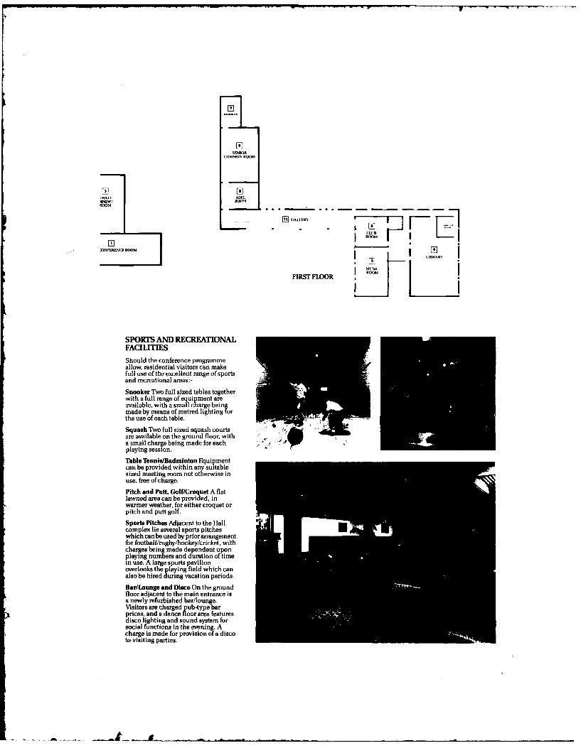
,OMMON ROOM
MALL. A[WA.lINNG RXMM
RROOM
;MALLEL
DNFCRULNE ROOM
FIRST FLOOR L 1
SPORS AND RECREATIONALFACILITIES
Should the conference programmeallow, residential visitors can makefoil use of the excellent range of sportsand recreational areas:-
alc arg-eIn [-
Snooker Two full sized tables togetherwith a full range of equipment areavailable, with a sma Ilhre enmade by means of metred lighting forthe use of each table. -Squash Two full sized squash courtsare available on the ground floor, with --a small charge being made for eachplaying session.
Table Tennis/Badminton Equipmentcan be provided within any suitablesized meeting room not otherwise inuse, free of charge.
Pitch and Putt, Golf/Croquet A flatlawned area can be provided, inwarmer weather, for either croquet orpitch and putt golf.
Sports Pitches Adjacent to the Halcomplex lie several sports pitcheswhich canbe used by priorarrangementfor football/rugby/hockey/cricket, withcharges beingade dependent uponplaying numbers and duration of timein use. A large sports pavilionoverlooks the p laying field which canalso be hired during vacation periods.
Bar/Lounge and Disco On the groundfloor adlacent to the main entrance isa newly refurbished bar/lounge.Visitors are charged b type barprices, and a dance Ro area feat uredisco lighting and sound system forsocial functions in the evening. Acharge is made for provision of a discoto visiting parties.
V
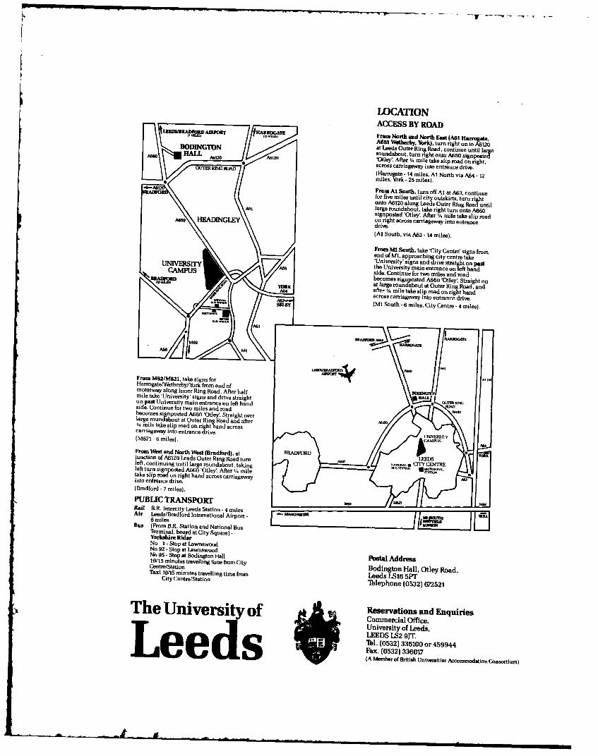
LOCATIONACCESS BY ROADRAM~aD~ Tm= From North and North (Ast A61 HarreasAml ~te .Yrk).tn right on to A6120ODINGTON at Leeds Outer Ring Road, continue until largeroundabout, turn right onto A60 signpot'Otley After % mile take slip road on right.across carriageway into entrance drive.RHrrogate - 14 miles, Al North via A64 - 12miles, York - 25 miles).From Al South, turn off Al at A63, continuefor five miles until city outskirts, turn rightonto A6120 along Leeds Outer Ring Road untillarge roundabout, take right turn onto A660signposted 'Otley'. After 1/. mile take slip road~AG HEADINGLEY on right across carriageway into entrancedrive.(Al South, via A63 - 14 miles).
From M! South, take 'City Centre' signs fromend of Ml, approaching city centre takeUniversity' signs and drive straight on pastUN IVERSTy the University main entrance on left handCAMPUS side. Continue for two miles and roadbecomes signposted A660 'Otley'. Straight onRI.fUOW at larg roondsabout at Outer Ring Road, andafter % mile take slip road on right hand/W across carriageway into entrance drive.
S a, (M1 South - 6 miles, City Centre - 4 miles).
M
From M62/M621, take signs forHarngat/Wtherby/York from end ofmotorway along Inner Ring Road. After halfmile take 'University' signs and drive straighton past University main entrance on left handside. Continue for two miles and roadbecomes signposted A660 'Otiey'. Straight overlarge roundabout at Outer Ring Road and after'14 mile take slip road on right hand acrosscarriageway into entrance drive.M621 - 6 miles).
From West and North West (Bradford), at BRADFaRDjunction of A6120 Leeds Outer Ring Road turnleft, continuing until large roundabout, takingleft turn signposted A660 'Otley'. After % miletake slip mad on right hand across carriagewayinto entrance drive.
(Bradford - 7 miles).
PUBLIC TRANSPORTRail B.R. Intercity Leeds Station - 4 milesAir Leeds/Bradford International Airport - - MAI--
6 milesBus (From B.R. Station and National BusTbrminal, board at City Square) -Yorkshire RiderNo I - Stop at LewnswoodNo 92 - Stop at LawnswoodNo 95 - Stop at Bodington Hall10/15 minutes travelling time from City AddressCentre/Station Bodtngton Hall, Quaey Road,Taxi 10/15 minutes travelling time from e
City Centre/Station'Iblephone (0532) 672521
The University of Reonrations and Enquifies
Univsity of Leeds,.3 LEEDS LS2 91T.- ' ~ ' 'IW. (0532) 336100 or 459944
Fax. (0532) 336017i e e d s (A Member of British Universitle Accommodation Consortium)
_m . .. .. ... . .4 _ a ......... ...
1 5th LEEDS-f.YON SYMP'OSIUMA ON T1?iff/07.O DC
TU1E FIlBOLOGIC4L DESIGN OF &MCHINE ELEMLNrI.
61h - 91/7 SEPTEMXBER /8
i li S', rnysium w il be field at Bodington Hll.~ U niversity of I eeds. Qik'v Rcvs2
TUES2DAIY 6!1; 5:' FWiftP
.'; 5 5s~ii !Kev'rtoe NAdl-
4tEDNEsD.IY 7th 5 T"~~
* t - 36~ .5e .i' ;I Review Papeis
0o' ;2 i t .ics:owt III se. Ils
Gcai
'I ~ ~ ~ ~ ~ 5 Rol'S-~ci cm :
NIm i 1irAI. LI n.
5Q) sessf,,i tIff Plaintus n
5.4' S(Yt~i tMBelts I
Sessioni IX Wear
I AtliaIv
H) 10 00O Session X Rollinz Elecni CII ar iny
session X/ Plain Hearings
Sssion X11 Ceramitcs
12..30 ( 011 5-'sim )(11 Al/I RetIvm Bearf'
I (1 -I. 3I S~ss nn XI' ieal/Mait ftic Hearin"
15.00 16/.00 Session XVI Knormleign Bae Systems
fiiockKlinigctW it fieldDouglas(iriffin
15th LEEDS-LYON SYMPOSIUM ON TRIBOLOGY
VISIT to NORTH YORKSHIRE MOORS - 8th SEPTEMBER 1988
As indicated on the final programme a visit to the North Yorkshire Moors has been
arranged for all delegates who wish to take part. on the afternoon and evening of
Thursday 8th September.
The North Yorkshire Moors form an area of outstanding natural beauty.
with many pretty inland villages and bounded on its eastern side by a rugged.
high-cliffed coastline and picturesque fishing villages. We have arranged four
separate visits. all including the North Yorkshire Moors. but visiting different
places of interest. Delegates may, with certain limitations noted below, choose
anyone of the four tours, but as the number of places on each tour is limited
tiis choice must be on a "first come" basis. Lists for registering for the tours
will be available at the Svsposium. Choice of tour must be indicated not later
than 11.00 a.m. Wednesday 7th September. All the tours conclude with Dinner at
the Crown Hotel. Boroughbridge.
The four tours on offer are:-
KILBURN (Woodcarving) and WHITBY
RIEVAULX ABBEY and WHITBY
NORTH YORKSHIRE MOORS RAILWAY and WHITBY
FYIINGDALES EARLY WARNING RADAR STATION and RIEVAULX ABBEY
Detailed itineraries for the four tours, are given below:
(a) KILBURN and WHITBY
Coach from Bodington Hall to Kilburn Village arriving at approximately 2.00 p.m.
Delegates will be able to visit the famous Thompson (Mouseman) furniture factory
and see traditional. hand-crafted and hand-carved solid oak furniture being made
and also to Niew the showroom. Note that there is no organised 'tour' of the
workshop but you will be free to wander. Departure from Kilburn is at 3,5.p.m.
and the coach then goes directly to Whitby. arri.ing at approximately 4.30.p.m.
Whitbv is a large fishing village of great character and visual charm. It is
split into two halves by the River Esk. and it was here that the explorer Captain
Cook was born and learned his seamanship. Whilby has historical connections with
the Victorian photographer. Frank Meadows Sutcliffe and was the setting for the
original Dracula sioiics b% Braim Stoker St. Mary's church is an extremely
interesting example of Norman architecture with a unique interior and is well
worth a visit. From the churchyard magnificent views of Whitby may be enjoyed
and immediatelv adjacent to the church are the ruins of the 13th century Abbey
A stone stairway with 199 steps leads down into the town. Delegates will have
approximately I',. hours free time in Whitby before the coach leaves at 6.00 p.m.
to arrive at the Crown Hotel. Boroughbridge at approximately 7.30.p.m. for
Dinner.
.,A £! . . . . -=i
(b) RIEVAULX ABBEY and WHITBY
Coach from Bodington Hall to Rievaulx Abbey. arriving at approximately 2.15.p.m.
Here delegates will be free to explore the Abbey at leisure. Rievaulx Abbey was
founded in 1131 by Monks of the Cistercian order and the ruins which still stand
have a soaring beauty which is awe inspiring, and are set in a steep, richly
wooded valley.
The coach will leave Rievaulx at 3.30.p.m. to arrive at Whitby at approximately
4.30 p.m. Departure from Whitby will be at 6.00,p.m.. giving delegates 1 t/ hours
free time in the town. The tour will conclude at the Crown Hotel, Boroughbridge
for Dinner.
(c) NORTH YORKSHIRE MOORS RAILWAY and WHITBY
Coach front Bodington Hall to Pickering. to arrive at approximately 2.30.pmn,
Pickering is a small market town surrounded by attractive farming land to the
south and moorland to the north and east. At Pickering delegates will board the
North Yorkshire Moors Railway train to depart at 2.50.p.m. The steam hauled
train will travel through wooded slopes, steep gorges. moorland and nature
reserves to arrive at Grosmont at 3.55.p.m. The line was originally built by
George Stephenson in 1836. At Grosmont delegates will once again join the coach
for a short ride to Whitby arriving at approximately 4.30.p.m. Once again there
will be approximately I V: hours free time before departing Whitby at 6.00.p.m. for
Dinner at the Crown Hotel. Boroughbridge.
(d) FYLINGDALES EARLY WARNING RADAR STATION and RIEVAULX ABBEY
[Please note that this tour is restricted to delegates who come from the
NATO countrics or fron Australia and New Zealandi.
Coach from Bodington Hall to Royal Air Force Fylingdales to art ive at
approximately 3.00.p.m. Here delegates will take part in a guided tour of the
establishment and will be able to see the current range of early warning radars
*and some of the engineering aspects of the radar superstructures including the
advanced rolling element support bearings. Departure from Fylingdales is at
5.00.p.m. and the tour then goes to Rievaulx Abbey to arrive at approximately
5.45.p.m. Delegates will have 45 minutes to explore the Abbey before departing
at 6.30.p.m. for the Crown Hotel for Dinner. arriving at Boroughbridge at
approximately 7.15.p.m.
B. Jobbins
eptember 1988
15th LEEDS-LYON SYMPOSIUM ON TRIBOLOGY
THE TRIBOLOGICAL DESIGN OF MACHINE ELEMENTS
6th - 91h SEPTEMBER 1988
NOTE TO AUTHORS:
11] There have been some modifications to the preliminary programme already distributed.
Please find enclosed an outline of the final programme indicating the time at which
you will be making your presentation.
[2/ All technical sessions will be held at Bodington Hall. the University Hall of
Residence where delegates are being accommodated.
/31 The usual audio-visual facilities will be available in the main conference room:-
blackboard, overhead projector, 2 x 2 slide projector, film projector and microphone
(if required). For the parallel sessions an overhead projector and slide projector
will be available and other requirements should be notified.
141 A projectionist will be available throughout the Symposium and slides may be handed
to him before the session. Notice of any special requirements e.g. films, would he
appreciated. Slides may be indexed by the presenter himself, or the projectionist.
as required.
/51 On this occasion only written discussions will be accepted for publication in the
final proceedings. This will be circulhted to authors by mid-October and repiies
must be provided by mid-November to meet the publishing deadline.
/6/ TIMING
The schedule for the Symposium is extremely tight and athors must limit themselves
to 15 minutes pesentation time. Session Chairmen will be asked to be firm in
ensuring that their session runs to time and that each presenter has a fair share of
the time available. Review papers may have slightly longer for presentation by
agreement with the Chairman.
15t LEEDS-LYON SYMPOSIUM ON TRIBOLOGY
THE TRIBOLOGICAL DESIGN OF MACHINE ELEMENTS
6th - 9Mh SEPTEMBER 1988
NOTE TO SESSION CHAIRMEN:
1I1 The schedule for nearly all sessions is extremely tight and it would be appreciated if
Chairmen would firmly limit those authors who run over their allotted presented time.
Presentations should be limited to 15 minutes or slihtll y more for Review Papers
depending on the time wished for discussion.
121 It has been the tradition of Leeds-Lyon Symposia to have presentation of the papers in
sequence by delaying discussion and questions until all the papers have been read. In
this way each author should have a fair presentation time.
/3/ It would be appreciated if Chairmen could identify the presenter of the multi-author
papers and introduce presenters with a few biographical details.
14/ On this occasion only written discussions will be accepted for publication in the
Proceedings together with authors replies. Could Chairmen please encourage such
written discussion to be received in Leeds by early October at the latest.
Thank you.