Embed Size (px)
Citation preview

Version 2.1
May 2007
L-ACOUSTICS P SERIES
108P, 112P, SB15P
OPERATOR MANUAL

L-ACOUSTICS P Series Manual V2.1 7/12/2007 1
IMPORTANT SAFETY INSTRUCTIONS
The Lightning Flash with arrowhead symbol within an equilateral triangle is intended to alert the
user to the presence of uninsulated "dangerous voltage" within the product’s
enclosure that may be of sufficient magnitude to constitute a risk of shock to persons.
The exclamation point within an equilateral triangle is intended to alert the user to the presence
of important operating instructions in the literature accompanying the product.
WARNING: TO REDUCE THE RISK OF FIRE OR ELECTRIC SHOCK, DO NOT EXPOSE
THIS APPARATUS TO RAIN OR MOISTURE AND OBJECTS FILLED WITH LIQUIDS, SUCH AS
VASES, SHOULD NOT BE PLACED ON THIS APPARATUS.
1. Read these instructions.
2. Keep these instructions.
3. Heed all warnings.
4. Follow all instructions.
5. Do not use this apparatus near water.
6. Clean only with dry cloth.
7. Do not block any ventilation openings. Install in accordance with the manufacturer's instructions.
8. Do not install near any heat sources such as radiators, heat registers, stoves or other apparatus
(including amplifiers) that produce heat.
9. Do not defeat the safety purpose of the grounding-type plug. A grounding type plug has two
blades and a third grounding prong. The third prong is provided for your safety. If the provided
plug does not fit into your outlet, consult an electrician for replacement of the obsolete outlet.
10. Protect the power cord from being walked on or pinched particularly at plugs, convenience
receptacles and the point where they exit from the apparatus.
11. Only use attachments / accessories specified by the manufacturer.
12. Use only with the cart, stand, tripod, bracket, or table specified by the manufacturer, or sold with the apparatus. When a cart is
used, use caution when moving the cart/apparatus combination
to avoid injury from tip-over.
13. Unplug this apparatus during lightning storms or when unused for long periods of time.
14. Refer all servicing to qualified service personnel. Servicing is required when the apparatus has been damaged in any way, such as power-supply cord or plug is damaged, liquid has been spilled
or objects have fallen into the apparatus, the apparatus has been exposed to rain or moisture,
does not operate normally or has been dropped.
15. Since the mains power supply cord attachment plug is used as disconnect device, the plug should
always be easily accessible.
16. Fire ignition sources such as candles should not be placed on the product or in close proximity to
the product.

L-ACOUSTICS P Series Manual V2.1 7/12/2007 2
� Operating temperature: 0°C to 35°C
� Operating mains voltage: 95VAC-125VAC (@115V voltage selector position), 195VAC-250VAC
(@230V voltage selector position)
Before applying AC power, ensure that the voltage selector is correctly set for the
mains power source (115 V or 230 V) and that the fuse has the appropriate rating.

L-ACOUSTICS P Series Manual V2.1 7/12/2007 3
FOREWORD
Thank you for purchasing the 108P, 112P or SB15P self-powered loudspeaker system.
This manual is intended to provide you with the information you require to effectively install and
operate your P series loudspeaker in a variety of professional sound reinforcement applications.
We are confident that the information provided in this manual will be sufficient for most applications,
however, should you require further assistance your distributor or L-ACOUSTICS® are available to
provide additional technical support.
MANUAL ORGANIZATION
� The Introduction gives a brief presentation of coaxial technology and the P series.
� Chapter 1 introduces 108P , 112P and SB15P loudspeakers plus accessories
� Chapter 2 describes cabling and connections
� Chapter 3 discusses P Series applications
� Chapter 4 details 108P, 112P and SB15P installation procedures
� Chapter 5 outlines P Series loudspeaker operation
� Chapter 6 provides 108P, 112P and SB15P specifications

L-ACOUSTICS P Series Manual V2.1 7/12/2007 4
TABLE OF CONTENTS
IMPORTANT SAFETY INSTRUCTIONS ....................................................................................................1
FOREWORD...................................................................................................................................................3
MANUAL ORGANIZATION ........................................................................................................................3
TABLE OF CONTENTS ................................................................................................................................4
TABLE OF CONTENTS ................................................................................................................................4
LIST OF FIGURES..........................................................................................................................................5
1. THE P SERIES ............................................................................................................................................6
1.1 OVERVIEW.............................................................................................................................................. 9
1.2 108P, 112P SERIES PRESETS................................................................................................................... 12
1.3 SB15P PRESETS...................................................................................................................................... 13
1.4 108P DESCRIPTION............................................................................................................................... 14
1.5 112P DESCRIPTION............................................................................................................................... 15
1.6 SB15P DESCRIPTION ............................................................................................................................. 16
2. CONNECTORS and CABLES.................................................................................................................18
3. APPLICATIONS ......................................................................................................................................20
3.1 AIMING P SERIES ENCLOSURES............................................................................................................. 20
3.2 DISTRIBUTED SOUND REINFORCEMENT.............................................................................................. 21
3.3 108P NEARFIELD MONITORING............................................................................................................ 22
3.4 FLOOR MONITORING ........................................................................................................................... 22
4. INSTALLATION PROCEDURES............................................................................................................23
4.1 ETR8-2 U-BRACKET ATTACHMENT....................................................................................................... 23
4.2 ETR112XT U-BRACKET ATTACHMENT.................................................................................................. 24
4.3 XTLIFTBAR ATTACHMENT .................................................................................................................... 25
4.4 ETR15P U-BRACKET ATTACHMENT....................................................................................................... 26
4.5 SAFETY RULES....................................................................................................................................... 27
5. P SERIES LOUDSPEAKER OPERATION ..............................................................................................28
6. SPECIFICATIONS ...................................................................................................................................29
6.1 108P SPECIFICATIONS........................................................................................................................... 29
6.2 112P SPECIFICATIONS........................................................................................................................... 32
6.3 SB15P SPECIFICATIONS ......................................................................................................................... 36
WARRANTY AND DISCLAIMERS.............................................................................................................39
FACTORY SERVICE ....................................................................................................................................39
APPROVALS ................................................................................................................................................47
L-ACOUSTICS P Series Manual V2.1 7/12/2007 5
LIST OF FIGURES
Figure 1: 108P, 112P Loudspeaker Enclosures……………………………………………………………… 6
Figure 2: SB15P self-powered subwoofer…………………………………………………………………... 7
Figure 3: P Series Rigging Components……………………………………………………………………… 8
Figure 4: 108P Enclosure ……………………………………………………………………………………. 9
Figure 5: 112P Enclosure……………………………………………………………………………………. 10
Figure 6: SB15P Enclosure…………………………………………………………………………………... 11
Figure 7: 108P, 112P preset selector switch closeup and preset options………………………………….. 12
Figure 8: SB15P preset selector switch closeup…………………………………………………………….. 13
Figure 9: SB15P with positive polarity, 108P or 112P in X-OVER mode ………………………………….. 13
Figure 10: SB15P with negative polarity, 108P or 112P in FRONT mode ………………………………… 13
Figure 11: 108P (floor monitor orientation)………………………………………………………………... 14
Figure 12: 112P (floor monitor orientation)………………………………………………………………... 15
Figure 13: SB15P (with pole-mounted 108P )……………………………………………………………… 17
Figure 14a: 108P / 112P DSP Power Amplifier Module Rear Panel………………………………………... 18
Figure 14b: SB15P DSP Power Amplifier Module Rear Panel……………………………………………… 18
Figure 15: P Series mains power cables…………………………………………………………………….. 18
Figure 16: Daisy-chain connection of P Series enclosures………………………………………………….. 19
Figure 17: Connecting unbalanced sources…………………………………………………………………. 19
Figure 18: General guidelines for aiming P Series enclosures………………………………………………. 20
Figure 19: General guidelines for 108P or 112P enclosure spacing………………………………………… 21
Figure 20: ETR8-2 U-bracket installation procedure……………………………………………………….. 23
Figure 21: ETR112XT U-bracket installation procedure………………………………………………….... 25
Figure 22: XTLIFTBAR installation procedure………………………………………………………..……… 25
Figure 23: ETR15P U-bracket installation procedure…………………………………………….……… 26
Figure 24: 108P Line Drawing………………………………………………………………………….……. 30
Figure 25: 108P + ETR8-2 Line Drawing……………………………………………………………………. 31
Figure 26: 112P Line Drawing……………………………………………………………………………….. 32
Figure 27: 112P + ETR112XT Line Drawing………………………………………………………………... 34
Figure 28: 112P + XTLIFTBAR Line Drawing………………………………………………………………. 35
Figure 29: SB15P Line Drawing………………………………………………………………………………. 37
Figure 30: SB15P + ETR15P Line Drawing………………………………………………………………. 38
L-ACOUSTICS P Series Manual V2.1 7/12/2007 6
0. INTRODUCTION
The 108P and 112P combine the significant advantages of L-ACOUSTICS’ proven coaxial point
source technology with the convenience of self-powered performance and the power plus flexibility
of on-board digital signal processing.
Designed for portable applications, the 108P and 112P are suitable for distributed sound
reinforcement in theatre, congress centre, concert hall, trade show, corporate A/V, houses of
worship, club, or television applications. When used with the L-ACOUSTICS SB15P self-powered
subwoofer, the 108P and 112P can also be used for side fill, drum monitoring or small-to-medium
format front-of-house (FOH) applications. In addition to these applications, the 108P is specifically
optimized for use as a high-power nearfield monitor while the 112P provides a high-performance
stage monitoring solution.
The L-ACOUSTICS approach to distributed sound reinforcement starts with the specification that
each individual loudspeaker should behave as a coherent point source. This specification can be met
using coaxial components due to the fact that the directivity of the low and high frequency (LF and
HF) transducers is matched at the crossover frequency. This provides a smooth transition between LF
and HF sections with power response that is free of the polar lobing effects typical of traditional horn
/ woofer combinations. In addition, coaxial component directivity is horizontally, vertically and
diagonally symmetric (axi-symmetric), thus providing true point source behavior.
Extensive sound design and installation experience acquired by L-ACOUSTICS over the years
confirms this and we are confident that coaxial, axi-symmetric loudspeaker enclosures are the best
tools for multiple source, distributed sound reinforcement.
1. THE P SERIES
The L-ACOUSTICS P Series consists of: 108P and 112P self-powered loudspeaker enclosures, the
SB15P self-powered subwoofer and 108P, 112P, SB15P rigging accessories.
LOUDSPEAKER ENCLOSURES
(1) 108P
Self-powered 2-way coaxial loudspeaker with 100-degree axi-symmetrical coverage, containing
8” loudspeaker, 1” exit high frequency compression driver
(2) 112P
Self-powered 2-way coaxial loudspeaker with 90-degree axi-symmetrical coverage, containing
12” loudspeaker, 1.4” exit high frequency compression driver
108P
112P
Figure 1: 108P, 112P Loudspeaker Enclosures
L-ACOUSTICS P Series Manual V2.1 7/12/2007 7
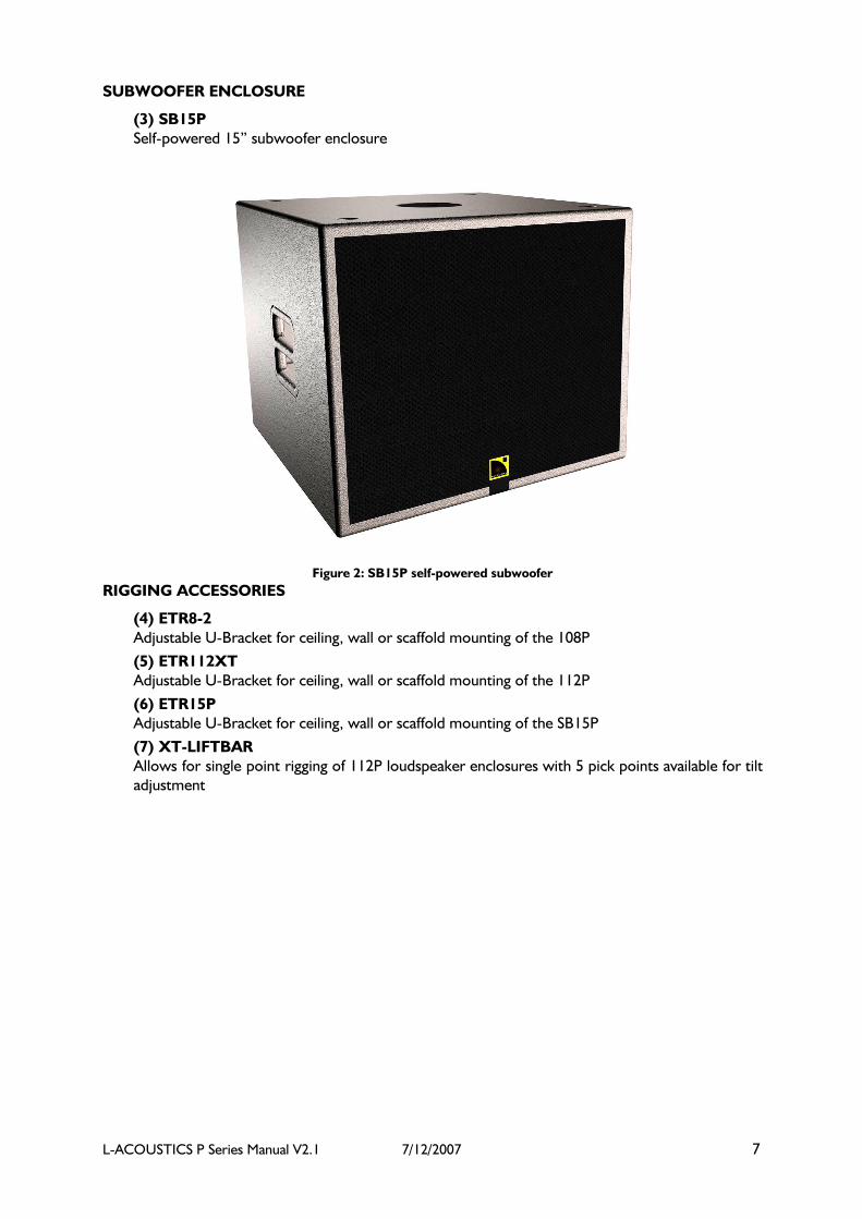
SUBWOOFER ENCLOSURE
(3) SB15P
Self-powered 15” subwoofer enclosure
Figure 2: SB15P self-powered subwoofer
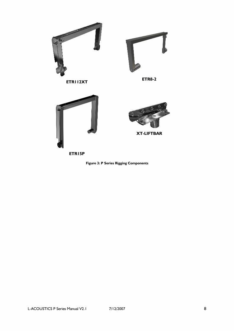
RIGGING ACCESSORIES
(4) ETR8-2
Adjustable U-Bracket for ceiling, wall or scaffold mounting of the 108P
(5) ETR112XT
Adjustable U-Bracket for ceiling, wall or scaffold mounting of the 112P
(6) ETR15P
Adjustable U-Bracket for ceiling, wall or scaffold mounting of the SB15P
(7) XT-LIFTBAR
Allows for single point rigging of 112P loudspeaker enclosures with 5 pick points available for tilt
adjustment
L-ACOUSTICS P Series Manual V2.1 7/12/2007 8
ETR112XT
ETR8-2
ETR15P
XT-LIFTBAR
Figure 3: P Series Rigging Components

L-ACOUSTICS P Series Manual V2.1 7/12/2007 9
1.1 OVERVIEW
L-ACOUSTICS 108P and 112P self-powered coaxial loudspeakers are intended for distributed sound
reinforcement in small- to medium-sized portable applications or for use with the SB15P self-
powered subwoofer for 3-way applications such as small- to medium-sized FOH or stage monitoring
(drum/side fill). All P-series enclosures feature highly-advanced loudspeaker components and rigging
accessories while benefiting from the sonic accuracy and flexibility afforded by application-engineered
digital presets.
108P
The 108P is a 250 x 500 watt bi-amplified, digitally-processed loudspeaker featuring a 1" exit HF
compression driver coaxially-loaded by an eight-inch low frequency transducer. Coaxial loading
produces coherent point source radiation with 100-degree axisymmetric directivity along with
superimposed LF/HF dispersion characteristics free of the polar lobing effects associated with
traditional 2-way studio monitor configurations (i.e., separate woofer/tweeter). The end result is
precise, stable image localization that is ideal for stereo or surround sound monitoring.
Integral digital crossover filtering, component time alignment and equalization provide superb sonic
performance plus added flexibility due to the availability of four application-engineered presets (FILL,
FRONT, MONITOR, X-OVER).
Accurate frequency response and imaging combined with elevated SPL output capacity make the
108P ideal for use as a high performance nearfield monitor for live FOH mix engineering and for
stereo or 5.1 monitoring in studio, broadcast or post production environments. For nearfield
monitoring applications, either FILL (free space conditions, for example, when the 108P is placed on
a console bridge) or MONITOR (half space conditions, for example, when the 108P is wall- or soffit-
mounted) presets should be selected.
Due to its’ high power:size ratio, plug-and-play ease-of-use, versatile application-oriented presets and
multi-purpose enclosure format, the 108P is also suitable for a wide variety of portable sound
reinforcement applications. For proximity reinforcement such as distributed front fill, the 108P
provides optimum fidelity and intelligibility, satisfying the strict requirements of classical music and
opera. The compact, truncated wedge-shaped enclosure format provides a visually-discrete solution
for floor monitoring, keyboard monitoring or underbalcony use and with the addition of L-
ACOUSTICS subwoofers, the 108P is also suitable for small format FOH applications.
In addition to proximity fill and monitoring, the 108P can be used for portable distributed sound
reinforcement in theatre, trade show, concert hall, houses of worship, congress centre, club,
restaurant, retail, corporate boardroom or television applications. To facilitate installation, a pole
mount socket is included as standard and an adjustable U-bracket is available as an optional rigging
accessory for ceiling, wall, scaffold or truss mounting.
Figure 4: 108P Enclosure

L-ACOUSTICS P Series Manual V2.1 7/12/2007 10
112P
Ideal for multi-purpose, portable sound reinforcement, the 112P features advanced loudspeaker
components powered by a 1000 W power amplifier module with dedicated on-board digital signal
processing. Four application-engineered presets are available (FILL, FRONT, MONITOR, X-OVER),
complementing the considerable flexibility of the 112P by providing convenient, plug-and-play ease of
operation.
Featuring a 1.4" exit compression driver coaxially-loaded by a 12" transducer, the 112P provides
coherent point source radiation with 90-degree axi-symmetric directivity (identical horizontal, vertical
and axial coverage). Due to the coaxial component configuration, power response is free of the polar
lobing effects typical of traditional horn / woofer combinations.
The net result is natural, studio monitor sound quality - ideal for proximity fill use or portable
distributed sound reinforcement in theatre, congress centre, concert hall, trade show, corporate A/V,
houses of worship, club, or television applications. When used with the L-ACOUSTICS SB15P self-
powered subwoofer, the 112P is also highly suitable for side fill, drum monitoring or small-to-
medium format front-of-house (FOH) applications.
Due to its compact, wedge-shaped enclosure format, the 112P provides an exceptionally high
performance floor monitor solution. Excellent image and coverage stability is obtained due to the
coaxial configuration and the performer experiences a generous, homogeneous coverage pattern
without the subjective impression and potential feedback problems of listening to a separate horn /
woofer combination.
To facilitate installation, pole mount sockets are included as standard and optional rigging accessories
include an adjustable U-bracket for ceiling, wall, scaffold or truss mounting and a liftbar adapter that
allows for single point rigging of the 112P (5 pick points available for tilt adjustment).
Figure 5: 112P Enclosure

L-ACOUSTICS P Series Manual V2.1 7/12/2007 11
SB15P
The SB15P (Sub Bass 15” Powered) is the companion subwoofer for L-ACOUSTICS 108P and 112P
self-powered coaxial loudspeakers. Featuring a front-loaded fifteen-inch transducer loaded in an
optimum-sized/-tuned vented enclosure, the SB15P combines the convenience of self-powered
performance with the power of digital signal processing.
The 15” component employed in the SB15P features elevated power handling and excursion
capability along with reduced distortion and thermal power compression. Advanced component
performance is complemented by integral power amplification and protection to provide exceptional
SPL output and secure operation. Optimized tuning provides an ideal combination of temporal
accuracy, bass articulation, musicality and low end definition that only a front-loaded subwoofer can
provide.
The compact dimensions of the SB15P provide a high degree of flexibility for installations where
space is at a premium. Typical applications include portable distributed sound reinforcement for
theatre, congress centre, concert hall, trade show, corporate A/V, houses of worship, club,
conference room, multimedia installations or television. The SB15P is also ideal for stage monitoring
applications such as compact side fill, keyboard or drum fill monitoring. For studio or nearfield
monitoring, the SB15P can be used with 108P enclosures in stereo, 5.1 or 7.1 configurations.
A built-in pole mount socket is provided as standard, facilitating the creation of a compact FOH
system when the SB15P is used with 108P or 112P enclosures. An adjustable U bracket is available as
an optional rigging accessory for ceiling, wall, scaffold or truss mounting, adding a unique degree of
versatility for fixed installation.
Figure 6: SB15P Enclosure

L-ACOUSTICS P Series Manual V2.1 7/12/2007 12
1.2 108P, 112P SERIES PRESETS
Four application-engineered presets are selectable via rear panel push button switch:
Figure 7: 108P, 112P preset selector switch closeup and preset options
Note: To memorize a preset (so that it is automatically recalled when cycling the mains
power on/off), select the desired preset and hold the preset selector button until the led
display is blinking.
FRONT presets are for standalone FOH operation (without subwoofers) where low and high
frequency shelving equalization provide a frequency response contour suitable for music
applications.
FILL presets provide nominally flat response for nearfield monitoring, speech reinforcement
and classical music applications or, in general, when P Series enclosures are used as a close
proximity fill enclosure.
FRONT and FILL presets are derived under freefield measurement conditions
MONITOR presets include additional low frequency equalization to account for half-space
loading conditions and are intended for floor monitoring applications or installations where P
Series loudspeakers are wall- or ceiling-mounted.
MONITOR presets are nominally flat under half-space measurement conditions
XOVER presets apply a 100 Hz highpass filter and a 3 dB high frequency shelving equalization
contour for use of the 108P or 112P with the L-ACOUSTICS SB15P self-powered subwoofer.
X - OVER 100 Hz HPF / 3 dB HF
Contour
(freefield conditions) APPLICATIONS: 3 - way system operation with SB15P self - powered subwoofer
MONITOR Nominally Flat (halfspace conditions) APPLICATIONS: Floor Monitoring, Wal l/Ceiling/Proscenium Mounted
FILL Nominally flat (freefield conditions) APPLICATIONS: Speech, classical, proximity fill
FRONT 3 dB LF/HF Contour (freefield conditions) APPLICATIONS: FOH (no subwoofers)
FLOOR COUPLING
FLOOR CANCELLATION
L-ACOUSTICS P Series Manual V2.1 7/12/2007 13
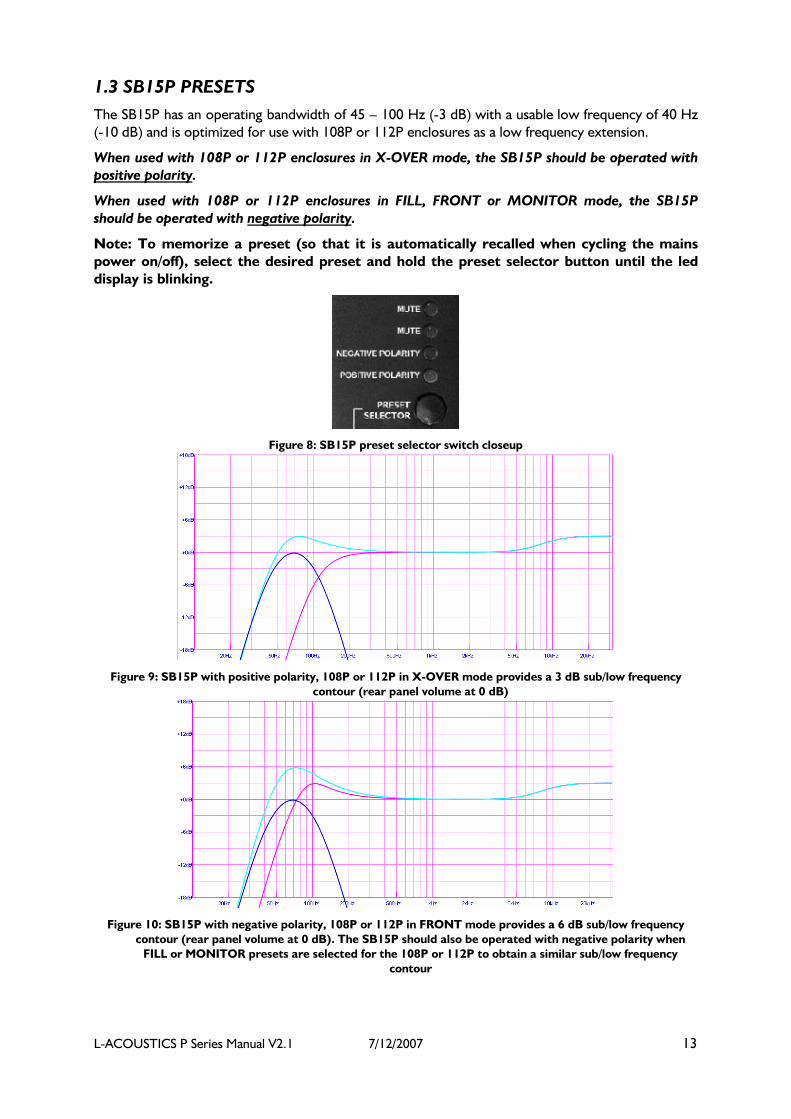
1.3 SB15P PRESETS
The SB15P has an operating bandwidth of 45 – 100 Hz (-3 dB) with a usable low frequency of 40 Hz
(-10 dB) and is optimized for use with 108P or 112P enclosures as a low frequency extension.
When used with 108P or 112P enclosures in X-OVER mode, the SB15P should be operated with
positive polarity.
When used with 108P or 112P enclosures in FILL, FRONT or MONITOR mode, the SB15P
should be operated with negative polarity.
Note: To memorize a preset (so that it is automatically recalled when cycling the mains
power on/off), select the desired preset and hold the preset selector button until the led
display is blinking.
Figure 8: SB15P preset selector switch closeup
Figure 9: SB15P with positive polarity, 108P or 112P in X-OVER mode provides a 3 dB sub/low frequency
contour (rear panel volume at 0 dB)
Figure 10: SB15P with negative polarity, 108P or 112P in FRONT mode provides a 6 dB sub/low frequency
contour (rear panel volume at 0 dB). The SB15P should also be operated with negative polarity when
FILL or MONITOR presets are selected for the 108P or 112P to obtain a similar sub/low frequency
contour

L-ACOUSTICS P Series Manual V2.1 7/12/2007 14
1.4 108P DESCRIPTION
The 108P is a self-powered, bi-amplified, two-way coaxial full range loudspeaker containing one
direct radiating, bass reflex-loaded, weather-resistant 8-inch low frequency transducer and one 25
mm (1.0 inch) exit, 44 mm (1.7 inch) voice coil diameter, polyester diaphragm, compression driver.
The cone body of the 8-inch low frequency component provides pattern control loading for the
compression driver and yields a 100-degree conical directivity pattern that is axi-symmetric. As a full
range system, frequency response is 65 Hz to 20 kHz with less than +/- 3 dB variation and the
usable bandwidth is 50 Hz to 22 kHz (-10 dB).
The 108P contains internal digital signal processing electronics and a two-channel power amplifier.
The power amplifier provides 500 W continuous (1 kHz, 0.5% THD) into 4 ohms and 250 W
continuous (1 kHz, 0.5% THD) into 8 ohms for powering low and high frequency transducers,
respectively. The power amplifier provides thermal protection, short-circuit/overload output
protection, clip and RMS signal limiting. Digital processing electronics also provides corrective
component and system equalization, component time alignment and crossover filtering.
Four presets are selectable via rear-panel push button switch with the following characteristics: FILL
has nominally flat frequency response when the loudspeaker is used under freefield conditions;
FRONT has +3 dB low and high frequency shelving characteristics under freefield conditions;
MONITOR has nominally flat response under half-space loading conditions; X-OVER provides a 100
Hz high pass filter and +3 dB high frequency shelving characteristics for use of the 108P with the L-
ACOUSTICS SB15P self-powered subwoofer. Connection to the 108P is made via two parallel XLR
connectors and gain is controllable via rear panel volume potentiometer. AC power connectors are
PowerCon type and 115V or 230V operation is selectable via rear panel rotary switch.
The 108P has a truncated wedge shape with a curved front profile. Dimensions are 42.1 cm (16.6 in)
high, 25.0 cm (9.8 in) wide by 29.9 cm (11.8 in) deep. When used as a floor monitor, the front baffle
of the enclosure is oriented at 30° with respect to vertical. Enclosure weight is 12.8 kg (28.2 lbs) and
cabinet construction consists of 15 mm (0.6 in) and 18 mm (0.7 in) Baltic birch plywood with joints
that are sealed, screwed and rabbeted. The finish is maroon gray, high resiliency paint and the front
of the 108P is protected by a black powder-coated 1.5 mm (0.06 in) thick steel grill covered with
acoustically-transparent grille cloth. The 108P has a 35 mm (1.38 in) diameter pole mount socket
mounted on the bottom side and a recessed plate on the top side for rigging the enclosure in
conjunction with an adjustable U-bracket assembly.
Figure 11: 108P (floor monitor orientation)
L-ACOUSTICS P Series Manual V2.1 7/12/2007 15
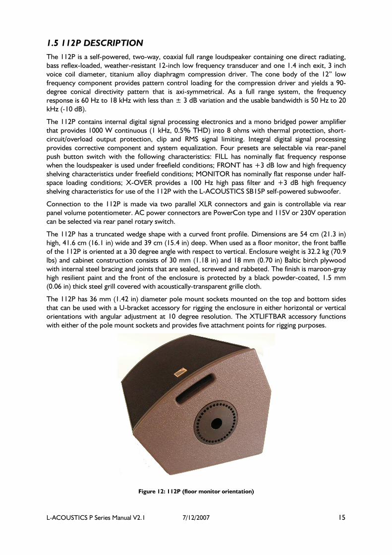
1.5 112P DESCRIPTION
The 112P is a self-powered, two-way, coaxial full range loudspeaker containing one direct radiating,
bass reflex-loaded, weather-resistant 12-inch low frequency transducer and one 1.4 inch exit, 3 inch
voice coil diameter, titanium alloy diaphragm compression driver. The cone body of the 12” low
frequency component provides pattern control loading for the compression driver and yields a 90-
degree conical directivity pattern that is axi-symmetrical. As a full range system, the frequency
response is 60 Hz to 18 kHz with less than ± 3 dB variation and the usable bandwidth is 50 Hz to 20
kHz (-10 dB).
The 112P contains internal digital signal processing electronics and a mono bridged power amplifier
that provides 1000 W continuous (1 kHz, 0.5% THD) into 8 ohms with thermal protection, short-
circuit/overload output protection, clip and RMS signal limiting. Integral digital signal processing
provides corrective component and system equalization. Four presets are selectable via rear-panel
push button switch with the following characteristics: FILL has nominally flat frequency response
when the loudspeaker is used under freefield conditions; FRONT has +3 dB low and high frequency
shelving characteristics under freefield conditions; MONITOR has nominally flat response under half-
space loading conditions; X-OVER provides a 100 Hz high pass filter and +3 dB high frequency
shelving characteristics for use of the 112P with the L-ACOUSTICS SB15P self-powered subwoofer.
Connection to the 112P is made via two parallel XLR connectors and gain is controllable via rear
panel volume potentiometer. AC power connectors are PowerCon type and 115V or 230V operation
can be selected via rear panel rotary switch.
The 112P has a truncated wedge shape with a curved front profile. Dimensions are 54 cm (21.3 in)
high, 41.6 cm (16.1 in) wide and 39 cm (15.4 in) deep. When used as a floor monitor, the front baffle
of the 112P is oriented at a 30 degree angle with respect to vertical. Enclosure weight is 32.2 kg (70.9
lbs) and cabinet construction consists of 30 mm (1.18 in) and 18 mm (0.70 in) Baltic birch plywood
with internal steel bracing and joints that are sealed, screwed and rabbeted. The finish is maroon-gray
high resilient paint and the front of the enclosure is protected by a black powder-coated, 1.5 mm
(0.06 in) thick steel grill covered with acoustically-transparent grille cloth.
The 112P has 36 mm (1.42 in) diameter pole mount sockets mounted on the top and bottom sides
that can be used with a U-bracket accessory for rigging the enclosure in either horizontal or vertical
orientations with angular adjustment at 10 degree resolution. The XTLIFTBAR accessory functions
with either of the pole mount sockets and provides five attachment points for rigging purposes.
Figure 12: 112P (floor monitor orientation)
L-ACOUSTICS P Series Manual V2.1 7/12/2007 16
1.6 SB15P DESCRIPTION
The SB15P self-powered subwoofer contains a single 15-inch loudspeaker component that is front-
loaded in an optimally-tuned and vented enclosure. Usable frequency response is 45 to 100 Hz with
less than ± 3 dB variation and the usable -10 dB low frequency response is 40 Hz. Loudspeaker ports
are of large area dimension in order to minimize port non-linearity and turbulence effects.
The fifteen-inch transducer has a 4-inch (100 mm) diameter edgewound copper ribbon voice coil, 18
mm (0.71 in) peak excursion capability, diecast aluminum frame, massive vented magnet structure
and high thermal capacity that provides reduced power compression, long term reliability and low
distortion output.
The SB15P features internal digital signal processing electronics and a mono bridged power amplifier
that provides 1000 W continuous (1 kHz, 0.5% THD) into 8 ohms with thermal protection, short-
circuit/overload output protection and clip / RMS signal limiting. Integral digital signal processing
performs crossover filtering (100 Hz low pass filter) and system equalization for use of the SB15P in
conjunction with the 108P or 112P. Positive or negative polarity operation is selectable via rear-panel
push button switch.
When used with 108P or 112P enclosures in X-OVER mode, the SB15P should be operated with
positive polarity.
When used with 108P or 112P enclosures in FILL, FRONT or MONITOR mode, the SB15P
should be operated with negative polarity.
Connection to the SB15P is made via two parallel XLR connectors and gain is controllable via rear
panel potentiometer. AC power connectors are PowerCon type and 115V or 230V operation is
selectable via rear panel slider switch.
The enclosure is constructed of 18 mm (0.7 in) baltic birch and is internally braced with steel corner
plates and sealed, screwed, rabbeted joints in order to remain vibration-free at extreme sound
pressure levels. Dimensions are 445 mm (17.5 in) high, 520 mm (20.5 in) wide and 520 mm (20.5 in)
deep and the enclosure weight is 36 kg (79.4 lbs). Finish is maroon-gray high resilient paint and the
front of the enclosure is protected by a black powder-coated, 1.5 mm (0.06 in) thick steel grill,
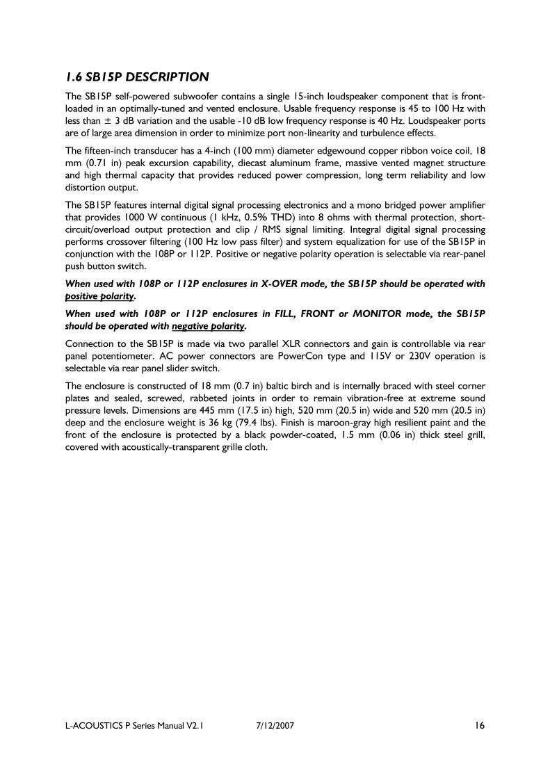
covered with acoustically-transparent grille cloth.
L-ACOUSTICS P Series Manual V2.1 7/12/2007 17
Two recessed handles are located on the sides of the SB15P for handling purposes and a 36-mm
(1.42 in) diameter pole mount socket mounted on the top side. When used in conjunction with a
bottom attachment plate, the pole mount socket can be used with the optional ETR15P U-bracket
accessory for rigging the enclosure in either horizontal or vertical orientations with continuous
angular adjustment.
Figure 13: SB15P (with pole-mounted 108P )

L-ACOUSTICS P Series Manual V2.1 7/12/2007 18
2. CONNECTORS AND CABLES
Figure 14a: 108P / 112P DSP Power Amplifier Module Rear Panel
Figure 14b: SB15P DSP Power Amplifier Module Rear Panel
Before applying AC power, ensure that the voltage selector is correctly set for the mains power
source (115 V or 230 V) and that the fuse has the appropriate rating.
Always use the mains power cable that was provided with your 108P, 112P or SB15P.
115V mains cable
230V mains cable
Figure 15: P Series mains power cables
Do not connect 108P, 112P or SB15P loudspeakers to an unearthed mains supply or by using
an unearthed mains cable.

L-ACOUSTICS P Series Manual V2.1 7/12/2007 19
To daisy-chain connect mains power from a 108, 112P or SB15P loudspeaker to additional P Series
enclosures (up to 3), use a cable with a grey Neutrik PowerCon NAC3FCB connector at one end
(connected to the Power Output connector of the P Series enclosure that is supplying power) and a
blue Neutrik PowerCon NAC3FCA connector at the other end (connected to the Power Input
connector of the P Series enclosure that is being daisy-chain connected).
Note: Neutrik PowerCon connectors are color-coded:
Blue = power input = Neutrik NAC3FCA PowerCon connector
Grey = power output = Neutrik NAC3FCB PowerCon connector
Never daisy chain connect more than 3 P series enclosures using the Power Output connector.
Do not daisy-chain connect P Series enclosures using an unearthed PowerCon NAC3FCA to
PowerCon NAC3FCAB cable.
Figure 16: Daisy-chain connection of P Series enclosures
These cables (NAC3FCA to NAC3FCB) must handle at least 5A@230V or 10A@115V.
SIGNAL INPUT/LOOP THROUGH
P Series loudspeakers are supplied with dual XLR connectors that are internally wired in parallel,
allowing for loop through connection and parallel operation of multiple 108P, 112P or SB15P
enclosures.
XLR connectors are wired as follows:
Pin 1 = ground
Pin 2 = signal +ve
Pin 3 = signal –ve
Unbalanced sources (for example, RCA or ¼” TS phone jack connectors) can be connected to the
108P or 112P provided that pin 3 is grounded to pin 1 (see Figure 17).
Figure 17: Connecting unbalanced sources

L-ACOUSTICS P Series Manual V2.1 7/12/2007 20
Note: When cabling your P Series loudspeaker for the first time, set the volume control fully counter-
clockwise (-∞). The input sensitivity of the 108P, 112P or SB15P can be matched to the output of the
mixing console (or other program source) by using the volume control on the rear panel.
The ferrite provided with your P series loudspeaker helps improve immunity to electromagnetic fields
(above 100 MHz) and should be placed on the XLR audio cable used for connecting input signal to
the 108P, 112P or SB15P. Perform a cable loop near the male XLR plug when attaching the ferrite.
3. APPLICATIONS
P Series loudspeakers are intended for portable distributed sound reinforcement, nearfield
monitoring (108P), floor monitoring or small- to medium-scale Front-Of-House (FOH) applications.
Guidelines for the use of P Series loudspeakers in these applications are discussed in this section.
3.1 AIMING P SERIES ENCLOSURES
Due to their controlled directivity behavior, P Series enclosures should be aimed so as to
geometrically cover the desired audience area with the main zero degree axis oriented towards the
middle or rear of the audience area. Since the wavefront radiated by an axi-symmetric sound source
has directivity that is smoothly increasing with frequency, this helps to match coverage, frequency
response and SPL to the acoustic environment of a typical auditorium (i.e., normally the
reverberation time in auditoria decreases smoothly above 1 kHz and at greater distances in the
venue, the low frequency energy is fairly constant due to the reverberant field).
Loudspeaker focus or aiming should be adjusted so that maximum HF energy is directed towards the
farthest listening areas – this helps to balance the SPL attenuation with distance that occurs in the
direct field. At closer listening positions, the off-axis attenuation at higher frequencies provides a
similar tonal balance and the overall SPL attenuation with distance is reduced.
Although P Series enclosures have controlled directivity attenuation properties it is important not to
have the first members of the audience too close to the system (i.e., in order not to produce
excessive sound pressure levels down front). Ideally, the ratio between the shortest and the furthest
distance covered should not exceed 1:4 and in order to obtain this throw distance ratio, it is often
desirable to fly the system. However, when P Series enclosures are flown and the audience seating
area begins very close to the stage, it is often necessary to use distributed front-fill speakers (for
example, 108P) or a stacked left/right 112P stereo infill system in order to improve coverage and
image localization for the first few rows of the audience.
90° opening angle
Figure 18: General guidelines for aiming P Series enclosures
L-ACOUSTICS P Series Manual V2.1 7/12/2007 21
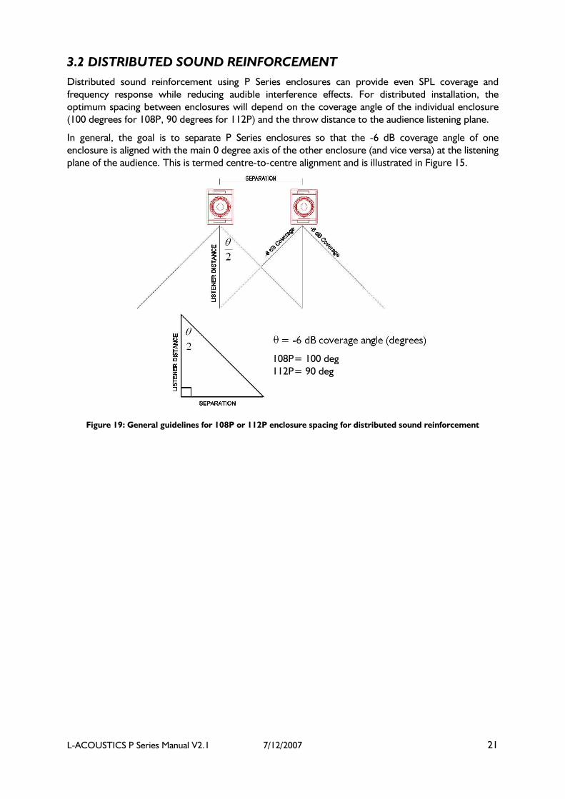
3.2 DISTRIBUTED SOUND REINFORCEMENT
Distributed sound reinforcement using P Series enclosures can provide even SPL coverage and
frequency response while reducing audible interference effects. For distributed installation, the
optimum spacing between enclosures will depend on the coverage angle of the individual enclosure
(100 degrees for 108P, 90 degrees for 112P) and the throw distance to the audience listening plane.
In general, the goal is to separate P Series enclosures so that the -6 dB coverage angle of one
enclosure is aligned with the main 0 degree axis of the other enclosure (and vice versa) at the listening
plane of the audience. This is termed centre-to-centre alignment and is illustrated in Figure 15.
108P= 100 deg
112P= 90 deg
Figure 19: General guidelines for 108P or 112P enclosure spacing for distributed sound reinforcement

L-ACOUSTICS P Series Manual V2.1 7/12/2007 22
3.3 108P NEARFIELD MONITORING
Accurate frequency response (due to on-board DSP) and imaging (due to the point source coaxial
configuration) combined with elevated SPL output capacity make the 108P ideal for use as a high
performance nearfield monitor for live FOH mix engineering and for stereo or 5.1 monitoring in
studio, broadcast or post production environments.
For nearfield monitoring, either FILL (free space conditions, for example, when the 108P is placed on
a console bridge) or MONITOR (half space conditions, for example, when the 108P is wall- or soffit-
mounted) presets should be selected.
For stereo monitoring, left/right 108P separation should be approximately equal to the throw
distance to the listening position. Horizontal azimuth (panning) should be adjusted so that the zero
degree axes of left/right 108P monitors are oriented towards the listening position.
3.4 FLOOR MONITORING
For floor monitoring, the coaxial component configuration employed in the 112P provides a high
degree of image and coverage stability. The benefits of axi-symmetric directivity are readily apparent
since the performer is in close physical proximity to the enclosure and experiences a generous,
homogeneous coverage pattern without the subjective impression (and potential feedback problems)
of listening to a separate horn / woofer combination.
The MONITOR preset accounts for half-space loading conditions, i.e., there is a 6 dB increase around
100 Hz (due to floor coupling), followed by a broad cancellation that occurs between 200 – 600 Hz
(due to floor reflections). The MONITOR preset compensates for these two half-space loading
effects and provides a nominally flat frequency response curve with excellent fidelity and feedback
resistance.
When using 112P enclosures in pairs for floor monitoring, the same principles apply as for distributed
systems, i.e., the optimum spacing between floor monitors depends on the coverage angle of the
enclosure (90 degrees for 112P) and the throw distance to the performing artist (which is determined
by the 30-degree floor monitor angle with respect to vertical and the artist’s height). Center-to-
center overlap will provide the most uniform coverage (see Figure 19) and it is not advised to angle
wedges in but to use them with the front faces parallel to each other (essentially, angling in wedges
no longer provides optimum center-to-center overlap).

L-ACOUSTICS P Series Manual V2.1 7/12/2007 23
4. INSTALLATION PROCEDURES
The ETR8-2 is an optional accessory U-Bracket for wall or ceiling mounting of the 108P.
Note: Always orient the ETR8-2 with the fixed arm on the bottom when installing the 108P in the
vertical orientation
4.1 ETR8-2 U-BRACKET ATTACHMENT
(1) 108P and ETR8-2 U-bracket
(2) Remove locking pin on the pivoting arm
(3) U-bracket stud mates with 108P pole mount socket
(4) Remove recessed set screw on adapter plate (if
necessary), rotate pivoting arm into position
(5) Attach pivoting arm using the tilt adjustment knob
(6) Secure the locking pin on the pivoting arm
(7) Rotate the U bracket to the desired position and securely
tighten the tilt adjustment knob.
(7) Three attachment points are available on ETR8-2 for
mounting the 108P in the horizontal orientation
Figure 20: ETR8-2 U-bracket installation procedure

L-ACOUSTICS P Series Manual V2.1 7/12/2007 24
4.2 ETR112XT U-BRACKET ATTACHMENT
The ETR112XT is an optional U-Bracket accessory for wall (vertical orientation) and ceiling or
scaffold (horizontal orientation) mounting of the 112P. Three mount holes are available on the center
section of the ETR112XT for bracket mounting. Pole mount adapter plates on the 112P in
conjunction with angle selection locking pins on the ETR112XT allow for 10 degree angular
resolution.
Note: When using ETR112XT in the vertical orientation, always install with the fixed arm on the bottom
and the pivoting arm on top.
(1) ETR112XT U-bracket
(2) Closeup of angle selection locking pin
(3) Remove locking pins on both U-bracket arms
(4) Release pivoting arm locking pin
(5) ETR112XT - ready for attachment
(6) 112P pole mount sockets mate with U-bracket studs
(mount fixed arm first)
(7) Rotate the pivoting arm into position – the pivoting arm locking pin
automatically secures the U-bracket
(8) Rotate the loudspeaker into position and select the desired angle.
Secure using the locking pins on both fixed and pivoting arms

L-ACOUSTICS P Series Manual V2.1 7/12/2007 25
(9) Front perspective view
(9) Rear perspective view
Figure 21: ETR112XT U-bracket installation procedure
4.3 XTLIFTBAR ATTACHMENT
The optional XTLIFTBAR accessory allows for single point rigging of 112P enclosures with 5 pick
points available for tilt adjustment. Pick point holes (from front to back) provide tilt angles of +18,
+11, +3, -5 or -13 degrees, respectively.
(1) XTLIFTBAR and the 112P enclosure
(2) The XTLIFTBAR mounting stud mates with 112P pole mount
sockets (top or bottom)
(3) When installing XTLIFTBAR, ensure that the main section is
aligned with the center of the enclosure in order to properly balance
the center of gravity.
(4) Two locking pins are used to secure the XTLIFTBAR. Shackle
locations (front to back) provide +18, +11, +3, -5, -13 degree tilt
angles, respectively
Figure 22: XTLIFTBAR installation procedure

L-ACOUSTICS P Series Manual V2.1 7/12/2007 26
4.4 ETR15P U-BRACKET ATTACHMENT
The ETR15P is an optional U-Bracket accessory for wall mounting (vertical orientation only – fixed
arm on the bottom / pivoting arm on top) and ceiling or scaffold mounting (horizontal orientation
only). Three mount holes are available on the center section of the ETR15P for bracket mounting and
an M8 threaded insert (8 mm diameter) provided on the rear of the SB15P for safety attachment.
Note: When using ETR15P in the vertical orientation, always install with the fixed arm on the bottom and
the pivoting arm on top.
(1) ETR15P U-bracket
(2) Release pivoting arm locking pin
(3) ETR15P - ready for attachment
(4) SB15P pole mount socket mates with U-bracket stud
(5) Mount fixed arm first
(6) Rotate the pivoting arm into position
(7) Rotate the SB15P to the desired angle and secure using the tilt
adjustment knob (pivoting arm locking pin automatically secures the U-
bracket as the adjustment knob is tightened)
(8) The recessed M8 insert (8 mm diameter) is available for attachment
of an I-Bolt plus safety steel
Figure 23: ETR15P U-bracket installation procedure

L-ACOUSTICS P Series Manual V2.1 7/12/2007 27
4.5 SAFETY RULES
L-ACOUSTICS loudspeakers can be ceiling-suspended or attached to a wall (vertical orientation only)
using accessories that are either supplied or recommended by L-ACOUSTICS only. Installation must
be done according to the following instructions :
Instructions Loudspeaker
Model
Accessory
model Wood support Incompressible plain support
(concrete or equivalent)
108P ETR8-2 Use 3 x self tapping screws with
minimum 8 mm diameter and 60
mm length (hexagonal head screw
DIN571 or equivalent)
Use 3 x anchors for heavy load 8
mm diameter and 50 mm length
minimum
112P ETR112XT Use 3 x self tapping screws with
minimum 8 mm diameter and 80
mm length (hexagonal head screw
DIN571 or equivalent)
Use 3 x anchors for heavy load
(10 mm diameter and 50 mm
length minimum)
112P XTLIFTBAR Do not suspend the loudspeaker
from this type of support
Use a tested rigging point (130 kg)
and in conformity with national
safety regulations of the country
of installation
SB15P ETR15P Use 3 x self tapping screws with
minimum 8 mm diameter and 80
mm length (hexagonal head screw
DIN571 or equivalent)
Attach M8 (8 mm diameter) I-bolt
to rear threaded insert for
attachment of safety steel
Use 3 x anchors for heavy load
(10 mm diameter and 50 mm
length minimum)
Attach M8 (8 mm diameter) I-bolt
to rear threaded insert for
attachment of safety steel
The 108P or 112P can be used with a loudspeaker stand (L-ACOUSTICS recommends the K&M
21435 or equivalent). The footprint (base diameter) must be at least 1300 mm and withstand a
maximum centric load of 350 N (35 kg) or higher. Tripod stand legs must be completely opened and
the height must not exceed 2020 mm when used with the 108P and 1420 mm when used with the
112P.
Always ensure that the ETR112XT or ETR15P rotating arm is securely fastened by verifying that the
spring-loaded locking pin at the pivot point is correctly seated before adjusting the tilt angle of the
112P or SB15P.
When using ETR8-2, ETR112XT or ETR15P in the vertical orientation, always install the U-bracket
with the fixed arm on the bottom and the pivoting arm on top.
Maximum one 112P can be rigged per XTLIFTBAR.
L-ACOUSTICS recommends the use of safety steels at all times.
Attachment to concrete has not been investigated during the CSA approval.

L-ACOUSTICS P Series Manual V2.1 7/12/2007 28
5. P SERIES LOUDSPEAKER OPERATION
Before applying AC power, ensure that the voltage selector is correctly set for the
mains power source (115 V or 230 V) and that the fuse has the appropriate rating.
Set the rear panel volume potentiometer to the minimum setting, i.e., fully counter-clockwise (-∞)
Connect a program signal source (output from a mixing console, for example) to the XLR input of
the 108P or 112P. For unbalanced sources, refer to Figure 17.
Note: The LOOP connector (male XLR) can be used to daisy-chain up to six P Series enclosures.
Ensure that the program signal source (mixing console output) is muted before powering your P
series loudspeaker.
Power up the 108P, 112P or SB15P by connecting the PowerCon cable that was provided with your
P series loudspeaker to an appropriate mains power source.
Note: The Power Output connector (grey PowerCon receptacle on the rear panel of the P Series enclosure)
can be used to daisy-chain connect up to 3 additional P Series enclosures.
Note: Neutrik PowerCon connectors are color-coded:
BLUE = power input = Neutrik NAC3FCA PowerCon connector
GREY = power output = Neutrik NAC3FCB PowerCon connector
Select the desired preset for the 108P / 112P (FILL, FRONT, MONITOR or XOVER) and/or the
SB115P (POSITIVE or NEGATIVE polarity) using the rear panel “Preset Selector” switch (see Section
1.2 and 1.3 for further details concerning P Series presets).
When used with 108P or 112P enclosures in X-OVER mode, the SB15P should be operated with
positive polarity.
When used with 108P or 112P enclosures in FILL, FRONT or MONITOR mode, the SB15P should be
operated with negative polarity.
Note: To memorize a preset (so that it is automatically recalled after cycling the mains power
on/off), select the desired preset and hold the preset selector button until the led display is blinking.
Run program signal (e.g. CD player), and slowly bring up the mixing console output level to check
that gain structure is correct.
If necessary, adjust the rear panel volume potentiometer in order to obtain the desired system gain
structure.
Note: Signal LED illuminates when the input signal level is greater than -40 dBV.
Note: Clip LED illuminates when the amplifier output clip point is reached.

L-ACOUSTICS P Series Manual V2.1 7/12/2007 29
6. SPECIFICATIONS
6.1 108P SPECIFICATIONS
ACOUSTICAL PERFORMANCE
Frequency Response
Frequency response: 65 – 20k Hz (± 3 dB) (FILL preset)
Usable bandwidth: 55 – 22k Hz (-10 dB)
System Sensitivity
-21 dBu (0.071 Vrms) 94 dB SPL 65 – 20k Hz (FILL preset)
Nominal Directivity (-6 dB)
Axi-symmetrical 100° (± 15°)
System Output SPL
One enclosure 115dB (cont) 125 dB (peak) FILL preset
113 dB (cont) 123 dB (peak) XOVER preset
FILL preset provides nominally flat response under freefield conditions
XOVER preset applies a 100 Hz high pass filter and a 3 dB high frequency shelving eq contour
Components
LF 1 x 8” weather resistant loudspeaker (2” voice coil)
HF 1 x 1” exit compression driver (polyester diaphragm, coaxial assembly)
ELECTRICAL PERFORMANCE
Input
Type Electronically balanced (pin 2 hot)
Max Input Level +12 dBu (gain potentiometer at 0 dB position)
DSP
Sampling 24 bit / 48 kHz
Dynamic Range > 105 dBA
Amplifier
Output Power 1 x 500 W (4 ohms – LF section)
1 x 250 W (8 ohms – HF section)
Gain 32 dB
Enclosure
Height 421 mm 16.6 in
Width 250 mm 9.8 in
Depth 299 mm 11.8 in
Floor Monitor Angle 30 degrees with respect to vertical
Net Weight 12.8 kg 28.2 lbs
Shipping Weight 14.3 kg 31.5 lbs
Shipping Dimensions 490 x 330 x 370 mm
19.3 x 13.0 x 14.6 in
Connectors 2 x XLR, 2 x PowerCon
(input, loop through)
Material 15 mm, 18 mm Baltic birch plywood
Finish Maroon-gray™
Grill Black epoxy perforated steel with acoustically-transparent, technically-
advanced grille cloth
Rigging Integrated pole mount socket, adjustable U-bracket accessory available

L-ACOUSTICS P Series Manual V2.1 7/12/2007 30
Figure 24: 108P Line Drawing

L-ACOUSTICS P Series Manual V2.1 7/12/2007 31
Figure 25: 108P + ETR8-2 Line Drawing

L-ACOUSTICS P Series Manual V2.1 7/12/2007 32
6.2 112P SPECIFICATIONS
ACOUSTICAL PERFORMANCE
Frequency Response
Frequency response: 60 – 18k Hz (± 3 dB) (FILL preset)
Usable bandwidth: 50 – 20k Hz (-10 dB)
System Sensitivity
-21 dBu (0.071 Vrms) 96 dB SPL 60 – 18k Hz (FILL preset)
Nominal Directivity (-6 dB)
Axi-symmetrical 90° (± 20°)
System Output SPL
One enclosure 121dB (cont) 131 dB (peak) FILL preset
119 dB (cont) 129 dB (peak) XOVER preset
FILL preset provides nominally flat response under freefield conditions
XOVER preset applies a 100 Hz high pass filter and a 3 dB high frequency shelving eq contour
Components
LF 1 x 12” weather resistant loudspeaker (3” voice coil)
HF 1 x 1.4” exit compression driver (titanium diaphragm, 3” voice coil, coaxial assembly)
ELECTRICAL PERFORMANCE
Input
Type Electronically balanced (pin 2 hot)
Max Input Level +12 dBu (gain potentiometer at 0 dB position)
DSP
Sampling 24 bit / 48 kHz
Dynamic Range > 105 dBA
Amplifier
Output Power 1 x 1000 W (8 ohms)
Gain 32 dB
Enclosure
Height 540 mm 21.3 in
Width 416 mm 16.4 in
Depth 390 mm 15.4 in
Floor Monitor Angle 30 degrees with respect to vertical
Net Weight 32.2 kg 70.9 lbs
Shipping Weight 35.5 kg 78.2 lbs
Shipping Dimensions 615 x 470 x 465 mm
24.2 x 18.5 x 18.3 in
Connectors 2 x XLR, 2 x Power Con (input, loop through)
Material 18 mm, 30 mm Baltic birch plywood
Finish Maroon-gray™
Grill Black epoxy perforated steel with acoustically-transparent, technically-
advanced grille cloth
Rigging Integrated pole mount socket,
adjustable U-bracket and liftbar accessories available

L-ACOUSTICS P Series Manual V2.1 7/12/2007 33
Figure 26: 112P Line Drawing
L-ACOUSTICS P Series Manual V2.1 7/12/2007 34
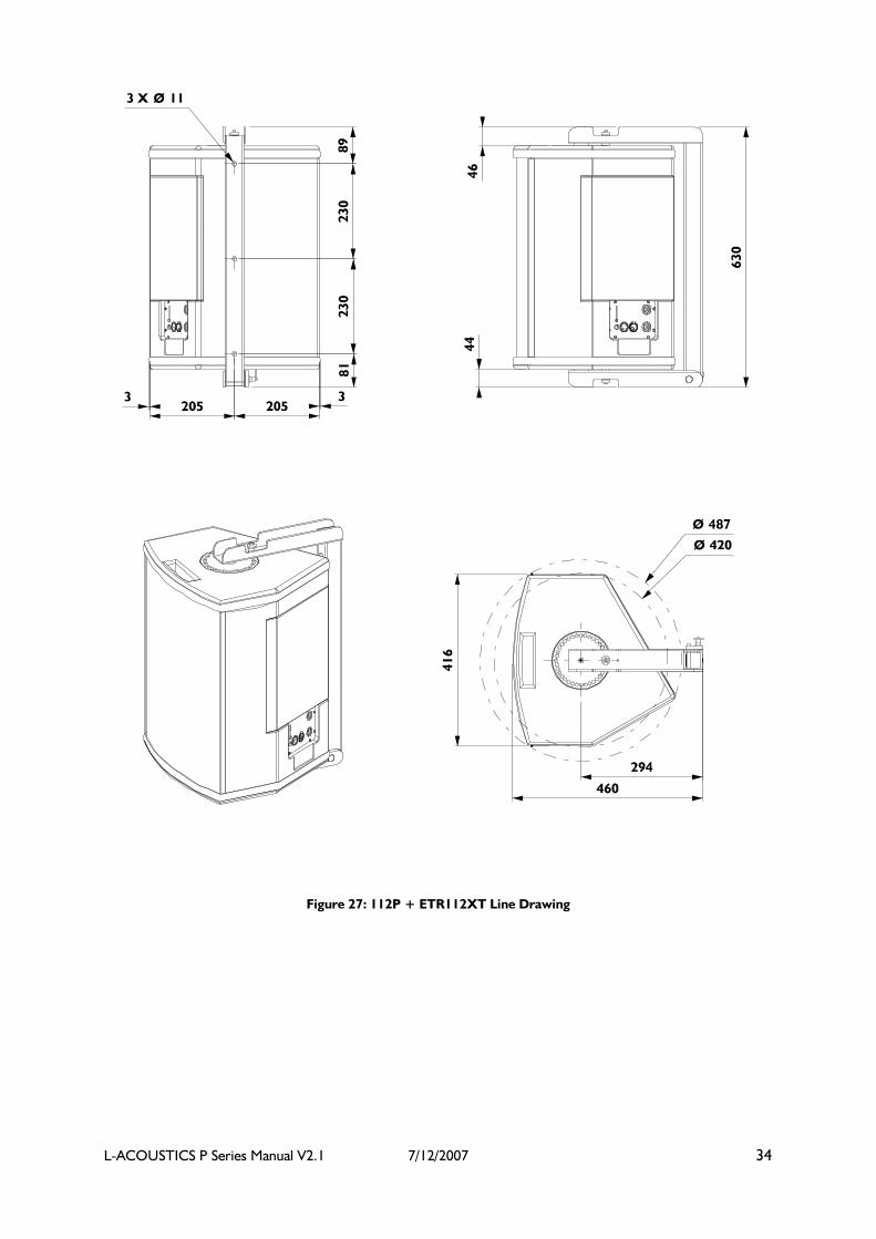
Figure 27: 112P + ETR112XT Line Drawing

L-ACOUSTICS P Series Manual V2.1 7/12/2007 35
Figure 28: 112P + XTLIFTBAR Line Drawing

L-ACOUSTICS P Series Manual V2.1 7/12/2007 36
6.3 SB15P SPECIFICATIONS
ACOUSTICAL PERFORMANCE
Frequency Response
Operating Bandwidth: 45 – 100 Hz (± 3 dB)
Usable Low Frequency: 40 Hz (-10 dB)
System Sensitivity
-21 dBu (0.071 Vrms) 93 dB SPL 45 – 200 Hz
System Output SPL
One enclosure 121dB (continuous) 131 dB (peak)
Two enclosures 127 dB (continuous) 137 dB (peak)
Three enclosures 133 dB (continuous) 143 dB (peak)
Components
1 x 15” weather resistant loudspeaker (4” voice coil)
ELECTRICAL PERFORMANCE
Input
Type Electronically balanced (pin 2 hot)
Max Input Level +12 dBu (gain potentiometer at 0 dB position)
DSP
Sampling 24 bit / 48 kHz
Dynamic Range > 105 dBA
Amplifier
Output Power 1 x 1000 W (8 ohms)
Gain 32 dB
Enclosure
Height 445 mm 17.5 in
Width 520 mm 20.5 in
Depth 520 mm 20.5 in
Net Weight 36 kg 79.4 lbs
Shipping Weight 38 kg 83.3 lbs
Shipping Dimensions 650 x 530 x 610 mm
25.6 x 20.9 x 24 in
Connectors 2 x XLR, 2 x Power Con (input, loop through)
Material 18 mm, 24 mm Baltic birch plywood
Finish Maroon-gray™
Grill Black epoxy perforated steel with acoustically-transparent, technically-
advanced grille cloth
Rigging Integrated pole mount socket,
adjustable U-bracket accessory available
Safety Insert for attachment of an I-Bolt

L-ACOUSTICS P Series Manual V2.1 7/12/2007 37
Figure 29: SB15P Line Drawing

L-ACOUSTICS P Series Manual V2.1 7/12/2007 38
Figure 30: SB15P + ETR15P Line Drawing

L-ACOUSTICS P Series Manual V2.1 7/12/2007 39
WARRANTY AND DISCLAIMERS
This product is warranted to be free from defects in components and factory workmanship under
normal use and service for a period of 3 years from the date of original purchase.
During the warranty period, L-ACOUSTICS or its nominated agents will undertake to repair, or at its
option, replace this product at no charge to its owner if it fails to perform as specified, provided that
the unit is returned undamaged and shipped pre-paid to the factory or an authorised service facility.
No other warranty is expressed or implied.
This warranty shall be null and void if the product is subjected to:
1) Repair work or alteration by persons other than those authorised by L-ACOUSTICS or its
agents.
2) Operation with incorrect AC voltage.
3) Shipping accidents, war, civil insurrection, misuse, abuse, operation with faulty associated
equipment or abnormal wear and tear. Units on which the serial number has been removed or
defaced will not be eligible for warranty service.
4) L-ACOUSTICS will not be responsible for any incidental or consequential damages with respect
to the products warranted.
L-ACOUSTICS reserves the right to make changes or improvements in the design or manufacturing
without assuming any obligation to change or improve products previously manufactured.
FACTORY SERVICE
In the event that your L-ACOUSTICS product needs factory service, contact the L-ACOUSTICS
service department for return instructions and a Return Authorisation number.
Please note when returning products for service:
1. Use the original packing
2. Include a copy of the sales receipt, your name, return address, phone number, fax number and a
description of the defect.
3. Mark the Return Authorisation number on the outside of the packing.
4. Ship the product prepaid to:
INTERNATIONAL:
L-ACOUSTICS
Attention : SAV
Parc de la Fontaine de Jouvence
91462 Marcoussis
France
Telephone: +33 (0)1 69 63 69 63
Fax: +33 (0)1 69 63 69 64
E-mail: [email protected]
NORTH AMERICA:
L-ACOUSTICS US
Attention : After Sales Service
2201 Celsius Avenue, Unit E
Oxnard, CA
93030 USA
Telephone: +1 (805) 604 0577
Fax: +1 (805) 604 0858
E-mail: [email protected]
L-ACOUSTICS P Series Manual V2.1 7/12/2007 40
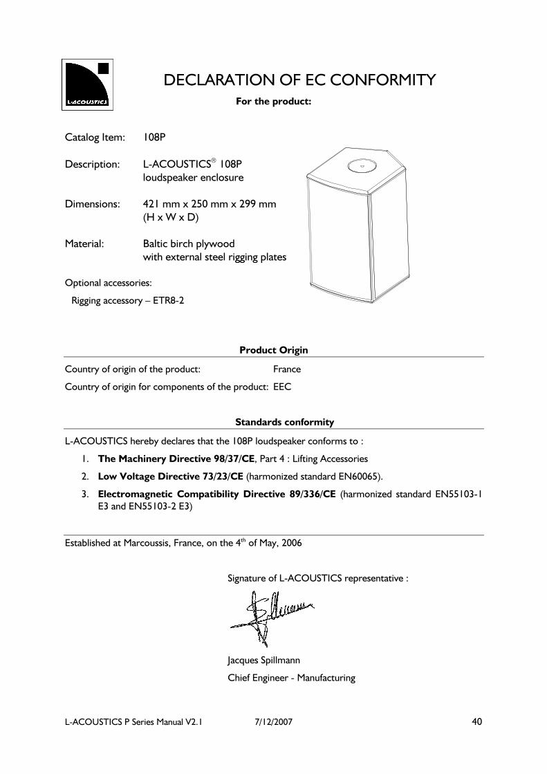
DECLARATION OF EC CONFORMITY
For the product:
Catalog Item: 108P
Description: L-ACOUSTICS 108P
loudspeaker enclosure
Dimensions: 421 mm x 250 mm x 299 mm
(H x W x D)
Material: Baltic birch plywood
with external steel rigging plates
Optional accessories:
Rigging accessory – ETR8-2
Product Origin
Country of origin of the product: France
Country of origin for components of the product: EEC
Standards conformity
L-ACOUSTICS hereby declares that the 108P loudspeaker conforms to :
1. The Machinery Directive 98/37/CE, Part 4 : Lifting Accessories
2. Low Voltage Directive 73/23/CE (harmonized standard EN60065).
3. Electromagnetic Compatibility Directive 89/336/CE (harmonized standard EN55103-1
E3 and EN55103-2 E3)
Established at Marcoussis, France, on the 4th of May, 2006
Signature of L-ACOUSTICS representative :
Jacques Spillmann
Chief Engineer - Manufacturing

L-ACOUSTICS P Series Manual V2.1 7/12/2007 41
DECLARATION OF EC CONFORMITY For the product:
Catalog Item: ETR8-2
Description: L-ACOUSTICS ETR8-2
rigging accessory
Dimensions: 485 mm x 225 mm x 50 mm
(H x W x D)
Material: Steel
Product Origin
Country of origin of the product: France
Country of origin for components of the product: EEC
Technical Specifications:
The ETR8-2 rigging accessory is intended for overhead suspension (horizontal or vertical orientation) of
MTD108a or 108P loudspeakers only. The following chart indicates the safety factor when using the ETR8-
2 rigging accessory with MTD108a or 108P loudspeakers according to the conditions described in the L-
ACOUSTICS MTD LINE OPERATOR MANUAL or the L-ACOUSTICS P SERIES OPERATOR MANUAL :
ETR8-2
Weight 1.9 Kg / 4.2 lbm
WLL 13 daN / 29.2 lbf
Ultimate Strength
Safety Factor >10
Standards conformity
MTD108a or 108P loudspeaker enclosures are designed to be suspended using the rigging accessory
ETR8-2 in the horizontal or vertical orientation. The ETR8-2 can be attached to an appropriate
support using 1, 2 or all 3 of the 9 mm diameter holes on the main bracket, refer to the appropriate
operator manual for detailed mounting instructions.
L-ACOUSTICS hereby declares that the ETR8-2 conforms to:
4. The Machinery Directive 98/37/CE, Part 4: Lifting Accessories
Established at Marcoussis, France, on the 4th of May, 2006
Jacques Spillmann, Chief Engineer - Manufacturing

L-ACOUSTICS P Series Manual V2.1 7/12/2007 42
DECLARATION OF EC CONFORMITY
For the product:
Catalog Item: 112P
Description: L-ACOUSTICS 112P
loudspeaker enclosure
Dimensions: 540 mm x 416 mm x 390 mm
(H x W x D)
Material: Baltic birch plywood
with external steel rigging plates
Optional accessories:
Rigging accessory – ETR112XT
Rigging accessory – XTLIFTBAR
Product Origin
Country of origin of the product: France
Country of origin for components of the product: EEC
Standards conformity
L-ACOUSTICS hereby declares that the 112P loudspeaker conforms to :
5. The Machinery Directive 98/37/CE, Part 4 : Lifting Accessories
6. Low Voltage Directive 73/23/CE (harmonized standard EN60065).
7. Electromagnetic Compatibility Directive 89/336/CE (harmonized standard EN55103-1
E3 and EN55103-2 E3)
Established at Marcoussis, France, on the 4th of May, 2006
Signature of L-ACOUSTICS representative :
Jacques Spillmann
Chief Engineer – Manufacturing

L-ACOUSTICS P Series Manual V2.1 7/12/2007 43
DECLARATION OF CE CONFORMITY
For the product:
Catalog Item: ETR112XT
Description: L-ACOUSTICS ETR112XT
Rigging accessory
Dimensions: 630 mm x 320 mm x 54 mm
Material: Steel
Product Origin
Country of origin of the product: France
Country of origin for components of the product: EEC
Technical Specifications :
The ETR112XT rigging accessory is intended for overhead suspension (horizontal or vertical orientation) of
112XT or 112P loudspeakers. The following chart indicates the safety factor when using the ETR112XT
rigging accessory according to the conditions described in the L-ACOUSTICS XT LINE OPERATOR MANUAL
or
L-ACOUSTICS P SERIES OPERATOR MANUAL:
ETR112XT
Weight 5.25 Kg / 11.6 lbm
WLL 56.5 daN / 127 lbf
Ultimate Strength
Safety Factor >12
Standards conformity
The ETR112XT is designed for the suspension of one 112XT or 112P loudspeaker enclosures only. The ETR112XT can be
attached to an appropriate support using 1, 2 or all 3 of the 11 mm diameter holes on the main bracket, refer to the
appropriate operator manual for detailed mounting instructions.
L-ACOUSTICS hereby declares that the ETR112XT conforms to :
8. The Machinery Directive 98/37/CE, Part 4 : Lifting Accessories
Established at Marcoussis, France, on the 4th of May, 2006
Jacques Spillmann, Chief Engineer - Manufacturing

L-ACOUSTICS P Series Manual V2.1 7/12/2007 44
DECLARATION OF EC CONFORMITY
For the product:
Catalog Item: XTLIFTBAR
Description: L-ACOUSTICS XTLIFTBAR
rigging accessory
Dimensions: 180 mm x 79 mm x 46 mm
(H x W x D)
Material: Steel
Product Origin
Country of origin of the product: France
Country of origin for components of the product: EEC
Technical Specifications :
The XTLIFTBAR rigging accessory is intended for overhead suspension (vertical orientation) of 112P, 112XT
or 115XT loudspeakers. The following chart indicates the safety factor when using the XTLIFTBAR rigging
accessory according to the conditions described in the L-ACOUSTICS XT LINE OPERATOR MANUAL or
L-ACOUSTICS P SERIES OPERATOR MANUAL:
XTLIFTBAR
Weight 0.55 Kg / 1.2
lbm
WLL 33 daN / 73 lbf
Ultimate Strength
Safety Factor >10
Standards conformity
The XTLIFTBAR is designed for the vertical suspension of 1 x 112P, 112XT or 115XT loudspeaker
only, refer to the appropriate operator manual for detailed mounting instructions.
L-ACOUSTICS hereby declares that the XTLIFTBAR conforms to :
9. The Machinery Directive 98/37/CE, Part 4 : Lifting Accessories
Established at Marcoussis, France, on the 4th of May, 2006

L-ACOUSTICS P Series Manual V2.1 7/12/2007 45
Jacques Spillmann, Chief Engineer - Manufacturing
DECLARATION OF EC CONFORMITY For the product:
Catalog Item: SB15P
Description: L-ACOUSTICS SB15P
loudspeaker enclosure
Dimensions: 445 mm x 520 mm x 520 mm
(H x W x D)
Material: Baltic birch plywood
with external steel rigging plates
Optional accessories:
Rigging accessory – ETR15P
Product Origin
Country of origin of the product: France
Country of origin for components of the product: EEC
Standards conformity
L-ACOUSTICS hereby declares that the SB15P loudspeaker conforms to :
10. The Machinery Directive 98/37/CE, Part 4 : Lifting Accessories
11. Low Voltage Directive 73/23/CE (harmonized standard EN60065).
12. Electromagnetic Compatibility Directive 89/336/CE (harmonized standard EN55103-1
E3 and EN55103-2 E3)
Established at Marcoussis, France, on the 4th of May, 2006
Signature of L-ACOUSTICS representative :
Jacques Spillmann
Chief Engineer – Manufacturing

L-ACOUSTICS P Series Manual V2.1 7/12/2007 46
DECLARATION OF CE CONFORMITY
For the product:
Catalog Item: ETR15P
Description: L-ACOUSTICS ETR15P
Rigging accessory
Dimensions: 527 mm x 415 mm x 60 mm
Material: Steel
Product Origin
Country of origin of the product: France
Country of origin for components of the product: EEC
Technical Specifications :
The ETR15P rigging accessory is intended for overhead suspension (horizontal or vertical orientation) of the
SB15P loudspeaker. The following chart indicates the safety factor when using the ETR15P rigging
accessory according to the conditions described in the L-ACOUSTICS P SERIES OPERATOR MANUAL:
ETR15P
Weight 5.3 Kg / 11.7 lbm
WLL 36 daN / 80.9 lbf
Ultimate Strength
Safety Factor >12
Standards conformity
The ETR15P is designed for the suspension of one SB15P loudspeaker enclosure only. The ETR15P can be attached to an
appropriate support using 1, 2 or all 3 of the 11 mm diameter holes on the main bracket, refer to the P Series Operator
manual for detailed mounting instructions.
L-ACOUSTICS hereby declares that the ETR15P conforms to :
13. The Machinery Directive 98/37/CE, Part 4 : Lifting Accessories
Established at Marcoussis, France, on the 4th of May, 2006
Jacques Spillmann, Chief Engineer - Manufacturing

L-ACOUSTICS P Series Manual V2.1 7/12/2007 47
APPROVALS
This equipment conforms to the requirements of Low Voltage Directive 73/23/EEC and
the EMC directive 89/336/EEC.
This equipment also conforms to the following standards:
EMC Emission EN55103-1, E3
EMC Immunity EN55103-2, E3
EMC 47 CFR FCC Part 15 of 2005
EMC CISPR 13 of 2003
Electrical Safety EN60065, Class I
For 115V use only
CAN/CSA 60065-03 - Audio, Video and Similar Electronic Apparatus - Safety Requirements.
UL Std No. 60065-03 - Audio, Video and Similar Electronic Apparatus - Safety Requirements.