Embed Size (px)
Citation preview

Product catalogue
Product catalogue_SA_Ver_11.doc Page 1 of 41 © FORCE Technology
Edition 11 issued: 23.10.2008
Scanners and
Accessories
Edition 11

Product Catalogue
Scanners and accessories
Product catalogue_SA_Ver_11.doc Page 2 of 41 © FORCE Technology
Date issued: 23.10.2008
INTRODUCTION 4
STANDARD AUTOMATIC SCANNERS 5
GENERAL-PURPOSE MAGNETIC WHEEL SCANNER: AGS-1 5 GENERAL PURPOSE MAGNETIC WHEEL SCANNER: AGS-2 8 COMPACT MAGNETIC WHEEL XY SCANNER: AUS-3 10 EASY OPERATED XY SCANNER FOR PIPE INSPECTION: APS-3 120/225 11 SCANNER FOR NON-FERROMAGNETIC PIPES APS-6 12 TRACK SCANNER FOR LARGE OR NON-FERRITIC STRUCTURES: ATS-1 13 WINDMILL TOWER PRODUCTION CONTROL SCANNER AMS-41 15
MANUAL SCANNERS 16
GENERAL PURPOSE MANUAL SCANNER: MWS-5 16 MANUAL SCANNER MWS-6 16
SPECIAL APPLICATION SCANNERS 17
STEAM COLLECTOR SCANNER AMS-6 17 INSPECTION OF SMALL DIAMETER NOZZLES: AWS-8 17 PORTAL SCANNER AMS-18 17 PIPE SCANNER: AMS-11 18 PIPE WELD SCANNER AMS-35 18 TUBE-TO-TUBE SHEET WELD INSPECTION: AHS-1 18 REMOTE UT INSPECTION OF UNDERGROUND STORAGE TANKS: AMS-1T 19 SCANNER FOR UNDERGROUND STORAGE TANKS AMS-28 19 WATER JET PROBE SCANNER AMS-22 19 AUTOMATIC TRACK SCANNER ATS-2 20 MOBILE WIND TURBINE BLADE SCANNER AMS-20 20 WIND TURBINE BLADE BRACING SCANNER AMS-40 20 FORCE TECHNOLOGY IMMERSION TANK SCANNER SOLUTIONS 21 AUTOMATIC IMMERSION TANK SCANNER AMS-36 21 AUTOMATIC IMMERSION TANK SCANNER AMS-30 21 AUTOMATIC IMMERSION TANK SCANNER AMS-38 22 AUTOMATIC IMMERSION TANK SCANNER AMS-43 22 WIND TURBINE SHAFT SCANNER AMS-32 23 SUCTION ROLL SHEET SCANNER AMS 33 23 AUTOMATIC RING SCANNER AMS-37 23 BRAZED JOINT SCANNER AMS-39 24
MODULAR SCANNER SYSTEM 25
INTERFACE ELECTRONICS TO P-SCAN SYSTEMS 26 Small Remote Control RCU-4 26
MOTORS 27 90W DC gear motor: MZR-2-66:1(X); MZR-3-14:1(Y) 27
INTERFACE ELECTRONICS TO THIRD PARTY EQUIPMENT 27 Master module for interface to third-party motor driver & controller: MST4A/B 27
OUTPUT GEAR HEADS 28 Straight output gear: STG-2 28 Right angle gear: ANG-1 28 Worm gear: WOG-1 28 Worm gear: WOG-2 29 Harmonic Drive Gear: HDG-1 29 Harmonic Drive Gear: HDG-2 29
OUTPUT MODULES 30 Y-module rail system: YMO-2 30 2.1.1 Telescopic Y-module: YMO-2 31

Product Catalogue
Scanners and accessories
Product catalogue_SA_Ver_11.doc Page 3 of 41 © FORCE Technology
Date issued: 23.10.2008
Magnetic wheel set: MAW-3 (LH + RH) 31 CONTROL AND MEASUREMENT SENSORS 32
Inclinometer. Guiding unit 120°: ICM-2 32 External incremental encoder: ENC-6-1 32
SCANNER CONTROL 33
P-SCAN INTERFACE 33 System communication 33 System configuration 34
SCANNER CONTROLLER WITH PC INTERFACE 36 THIRD-PARTY CONTROLLER 37
ACCESSORIES 38
PROBE HOLDERS 38 PROBE HOLDER ARMS 39
Springloaded probe holder arms: PHA-25/50/75 39 Special probe holder arms 40
PROBE RAILS: 40 Probe rails. PBH-1 40 Probe rails: PBR-2-90 40
PROBE BAR: 40 Bar for dual probe set-up: PBD-1 40
COUPLING MEDIA PUMPS 41 Peristaltic water pump: DCP-1 41 Gear Pump: DCP-4 41
Product Catalogue
Scanners and accessories
Product catalogue_SA_Ver_11.doc Page 4 of 41 © FORCE Technology
Date issued: 23.10.2008
Introduction
Dear Customers,
FORCE Technology delivers a full range of high quality scanners and robot systems for all types of industrial automated inspection. From robust pipe scanners to advanced innovative multi-axis robots for complex geometry nozzle inspection and dedicated modular built scanners for special inspection jobs.
For jobs where no existing scanner system can perform the required inspection, FORCE Technology designs total scanner systems for use in rough environments within e.g. the nuclear, offshore, and petrochemical industries.
As a standard, the scanners are delivered with control interface to the FORCE Technology P-scan system. As an option, many of the scanners can be delivered with interface to a third-party motor controller / inspection system.
Part of our product assortment is accessories needed for performing inspection jobs. The accessories and the modular scanner components are both sold separately or in combination with a scanner system.
If in this product catalogue, you miss a special scanner or just a component you need for an inspection job, please do not hesitate to contact us. Development is a continuous process so perhaps we have already developed or are developing the component you require. Otherwise we shaIll be pleased to cooperate with you in finding the best solution regarding both performance and price.
Please note that specifications may change without prior notice. More information can be found on our Internet web site http://www.p-scan.com.
If you need more information, please do not hesitate to contact [email protected] or directly mail to: [email protected]
Yours sincerely,
Peder Bent Hansen
E-mail: [email protected]
FORCE Technology
Div. for Sensor and NDE Innovation
Park Allé 345
DK-2605 Brøndby
DENMARK
Phone: +45 43 26 70 00
Fax: +45 43 26 70 11
E-mail: [email protected]

Product Catalogue
Scanners and accessories
Product catalogue_SA_Ver_11.doc Page 5 of 41 © FORCE Technology
Date issued: 23.10.2008
Standard automatic scanners The scanners range from a number of general-purpose magnetic wheel XY scanners to dedicated XY scanners for special geometries:
General-purpose magnetic wheel scanner: AGS-1
• General purpose magnetic wheel scanner for weld inspection and corrosion mapping, primarily of ferritic pipes and nozzles with an OD 75mm and upward.
• The scanner is based on the modular scanner components.
• Simple configuration / modification of scanner for different requirements etc. low height or high stability with long Y-module.
Specifications AGS-1
General Magnetic wheel scanner for pipe and nozzle inspection.
Control system P-scan or raw motor interface.
Operation on Min OD (circumferential drive) 75 mm
(longitudinal drive) 600 mm
Max OD plane plate
Materials ferritic
with sleeves also on non ferritic
Max speed X 75 mm/s
Y 200 mm/s
Dimensions L / W (stroke 270mm ) / H 420 x 370 x 105 mm
Weight ~8.2 kg

Product Catalogue
Scanners and accessories
Product catalogue_SA_Ver_11.doc Page 6 of 41 © FORCE Technology
Date issued: 23.10.2008
Pictures of AGS-1 (different configurations with 350 mm Y-module)
Standard configuration Low configuration (max height 75mm)
Special accessories AGS-1
Guide chain
When the scanner is used for weld inspection or operated on large diameter pipes a guide chain is used for securing scanner stability. Stainless steel chain is delivered in lengths of 5 m with assembly bracket. For simplified mounting on large diameter pipes chain with magnetic links can be delivered. The chain can be shortened to required length.
Guide rail
Used for guiding the scanner on large structures where guide chain can not be used. The Guide rail is attached to the structure with magnets or suction pads. The Guide rail is delivered with curvature to specifications.

Product Catalogue
Scanners and accessories
Product catalogue_SA_Ver_11.doc Page 7 of 41 © FORCE Technology
Date issued: 23.10.2008
Ferritic sleeves
For operating magnetic wheel scanners on non-ferritic pipes a set of seven sleeves is available covering a pipe range from OD 100 to 850 mm. The ferritic sleeve is mounted around the pipe with an integrated guide chain and the scanner is running on the sleeve.
Sleeves with a special diameter can be delivered on request.
Suction pad track
For operating the scanner on large non-ferritic structures a suction pad track is available. The track is flexible and can be mounted on structures with a curvature down to OD 1000 mm.

Product Catalogue
Scanners and accessories
Product catalogue_SA_Ver_11.doc Page 8 of 41 © FORCE Technology
Date issued: 23.10.2008
General purpose magnetic wheel scanner: AGS-2
The AGS-2 guidable magnetic wheel XY scanner is based on the modular system.
• General purpose magnetic wheel scanner for weld inspection and corrosion mapping of ferritic pipes and large structures with difficult access conditions.
• The scanner is based on the modular scanner components.
• Simple configuration / modification of scanner for different requirements etc. low height or high stability with long Y-module, longitudinal drive.
• Curved Y-modules is available as option for longitudinal inspection of pipes.
• Navigation from remote control or automatic tracking by means of gravity angle sensor / analogue proximity sensors / magnetic guide strip.
Specifications AGS-2 (preliminary, standard configuration)
General Guidable magnetic wheel scanner for inspection of pipes and large structures.
Control system P-scan or raw motor interface.
Operation on Min. OD (circumferential drive)
(longitudinal drive, special set-up)
(helical drive)
70 mm
150 mm
400 mm
Min. ID (circumferential drive)
(longitudinal drive)
450 mm
450 mm
Maximum dimensions plane plate
Materials ferritic steel
Speed X 60 mm/s
Y 210 mm/s
Dimensions L / W (stroke 270mm) / H (min. 65 mm) 420 x 350 x 105 mm
Weight ~13 kg

Product Catalogue
Scanners and accessories
Product catalogue_SA_Ver_11.doc Page 9 of 41 © FORCE Technology
Date issued: 23.10.2008
Drawings and pictures of AGS-2
Standard version
Guide sensors mounted on side of Y-module
Longitudinal drive on OD 600 mm and inspection with curved Y-module
Horizontal operation along guide strip:
Vertical operation with angle sensor:
Magnetic guide strip
Angle sensor
Guide sensor

Product Catalogue
Scanners and accessories
Product catalogue_SA_Ver_11.doc Page 10 of 41 © FORCE Technology
Date issued: 23.10.2008
Compact magnetic wheel XY scanner: AUS-3
• Magnetic wheel scanner for inspection of ferritic pipes from OD 70mm (OD 40mm with optional large rear wheels).
• Compact scanner body with two integrated motors, control electronics for PSP-4 and control panel. Motor axis has standard modular output flanges.
• Battery powered with PSP-4L system.
• Scanner body can be used as motor unit for other types of scanners.
Specifications AUS-3
General Compact magnetic wheel scanner for inspection of pipes.
Control system P-scan
Operation on Min OD (circumferential drive) 40 mm
(longitudinal drive) 200 mm
Max OD plane plate
Material ferritic steel
Speed X 23 mm/s
Y 110 mm/s
Dimensions L / W / H (with 350 mm YM) 350 x 245 x 67 mm
Weight 4,5 kg
Pictures AUS-3

Product Catalogue
Scanners and accessories
Product catalogue_SA_Ver_11.doc Page 11 of 41 © FORCE Technology
Date issued: 23.10.2008
Easy operated XY scanner for pipe inspection: APS-3 120/225
• Scanner series for weld inspection and corrosion mapping of pipes and pipe bends with diameter range 50-120mm or 110-225mm.
• XY scanner for fast and simple operation on all types of pipes due to clamping fixture and fork shaped scanner frame.
• Optional flexible Y-module fixture for inspection of nozzles on domes and large vessels.
Specifications APS-3
General Pipe scanner for inspection of all type of pipes due to clamp mounting.
Control system P-scan or other.
Operation Min - max OD APS-3, 120
APS-3, 225
50-120 mm
110-225 mm
Materials all solid
Speed X 25 mm/s
Y 200 mm/s
Stroke X 0 - 400°
Y (350 mm YM) 280 mm/s
Dimensions L / W / H
(350 mm YM)
APS-3, 120
APS-3, 225
400x297x477mm
500x396x477 mm
Weight With 350 mm
Y-module
APS-3, 120
APS-3, 225
11 kg
14 kg
Pictures APS-3

Product Catalogue
Scanners and accessories
Product catalogue_SA_Ver_11.doc Page 12 of 41 © FORCE Technology
Date issued: 23.10.2008
Scanner for non-ferromagnetic pipes APS-6
• Scanner for pipe inspection of ferritic and stainless steel pipes with a diameter down to 100mm.
• Transmission chain used for X motion.
• Can be configured with low profile height of 100 mm.
• For production control and in-service inspection.
Specifications APS-6
General Pipe scanner for inspection of all type of pipes due to chain mounting.
Control system P-scan
Operation on Min OD 100 mm
Max OD 1100 mm
Speed X 40 mm/s
Y 150 mm/s
Dimensions Min height 100 mm
Weight 5 kg

Product Catalogue
Scanners and accessories
Product catalogue_SA_Ver_11.doc Page 13 of 41 © FORCE Technology
Date issued: 23.10.2008
Track scanner for large or non-ferritic structures: ATS-1
• Because the scanner runs on its own track, the scanner is suitable for inspection of large structures, non-ferritic structures or structures with complex geometries.
• The scanner runs on special straight and/or curved tracks with a curvature > R300mm.
• High stability and accuracy due to rack and pinion driven scanner body.
• The track is attached to the inspection object with magnets, suction pads, arm system or clamps.
Specifications ATS-1
General The scanner is ideal for inspection of large structures, non-ferritic structures, structures with complex geometry and those with difficult surface conditions.
Control system P-scan or other
Track Track radius (teeth on outer radius) 200 mm - straight
Track radius (teeth on inner radius) 300 mm - straight
Speed X (standard gearing) up to 100 mm/s
X (special gearing) up to 180 mm/s
Y 200 mm/s
Dimensions L / W / H
(depending on configuration)
125x350x100 mm
Weight 6,5 kg
Pictures ATS-1

Product Catalogue
Scanners and accessories
Product catalogue_SA_Ver_11.doc Page 14 of 41 © FORCE Technology
Date issued: 23.10.2008
Accessories ATS-1
Tracks:
The ATS-1 scanner runs on a 25x25 mm track. Tracks are as standard delivered in straight 1.5 m elements that can be assembled with special brackets.
Special straight or curved tracks (or combina-tions) can be delivered on request.
Flexible Tracks:
For inspection applications where maximum stability is not needed but mounting flexibility is useful due to variations in object geometry a flexible plastic track is available. The flexible plastic track can be delivered in lengths up to 2 m. Minimum bending radius is approximately 350 mm.
Curved Y-module:
Primarily designed for corrosion mapping of pipe and pipe bends. A series of curved Y-modules can be delivered with rail radius from 150 mm. With two probes and 180° rail 100% scanning can be achieved in one run.

Product Catalogue
Scanners and accessories
Product catalogue_SA_Ver_11.doc Page 15 of 41 © FORCE Technology
Date issued: 23.10.2008
Track support:
Flexible arm system for attaching track to inspection object. Can be delivered with suction pads or permanent magnets.
Windmill tower production control scanner AMS-41
• Robust scanner system for production control of welds on cylindrical structures.
• The inspection object is rotated on e roller bed during inspection (X-movement).
• Probes are mounted in a probe holder frame That can be moved in the Y direction during scanning when necessary.
• The whole inspection system is placed on a robust trolley wagon for easy handling.

Product Catalogue
Scanners and accessories
Product catalogue_SA_Ver_11.doc Page 16 of 41 © FORCE Technology
Date issued: 23.10.2008
Manual scanners
General purpose manual scanner: MWS-5
• Manual scanner based on a general purpose scanner body with two input axis with integrated encoders.
• Standard version with magnetic wheels for: - Line scanning (also for TOFD). • Optional accessories can be delivered.
Manual scanner MWS-6
• Manual operated line scanner for composite structures
• Scanner body with one probe holder and encoder wheel
• The scanner has two operator controlled buttons with programmable function
• Accessories for scanning parallel with edge contour
• Width x length x height: 84 x 217 x 161 mm

Product Catalogue
Scanners and accessories
Product catalogue_SA_Ver_11.doc Page 17 of 41 © FORCE Technology
Date issued: 23.10.2008
Special application scanners
Steam Collector Scanner AMS-6
• Scanner dedicated for inside inspection of welds and surfaces in steam collector.
• XY scanner with three extra joints for positioning manipulator.
• Can inspect all relevant areas in collector without need for rebuild.
• Modular build scanner system for easy handling.
Inspection of small diameter nozzles: AWS-8
• Modular based scanner for inspection of small nozzle welds.
• By use of adapter rings and different scanner sleeves the scanner can be used for nozzles with OD 10-100mm.
• Requires a minimum vessel diameter of approx. 300mm and a vessel to nozzle diameter ratio > 2.5.
Portal scanner AMS-18
• Inspection of longitudinal welds in cylinder sheets
• Cylinders with diameter ranging from 500 mm to 2000 mm
• Wall thickness up to 115 mm
• X-rail length: 3300 mm
• X wagon with Y rail for 6 flexible probe holders
Product Catalogue
Scanners and accessories
Product catalogue_SA_Ver_11.doc Page 18 of 41 © FORCE Technology
Date issued: 23.10.2008
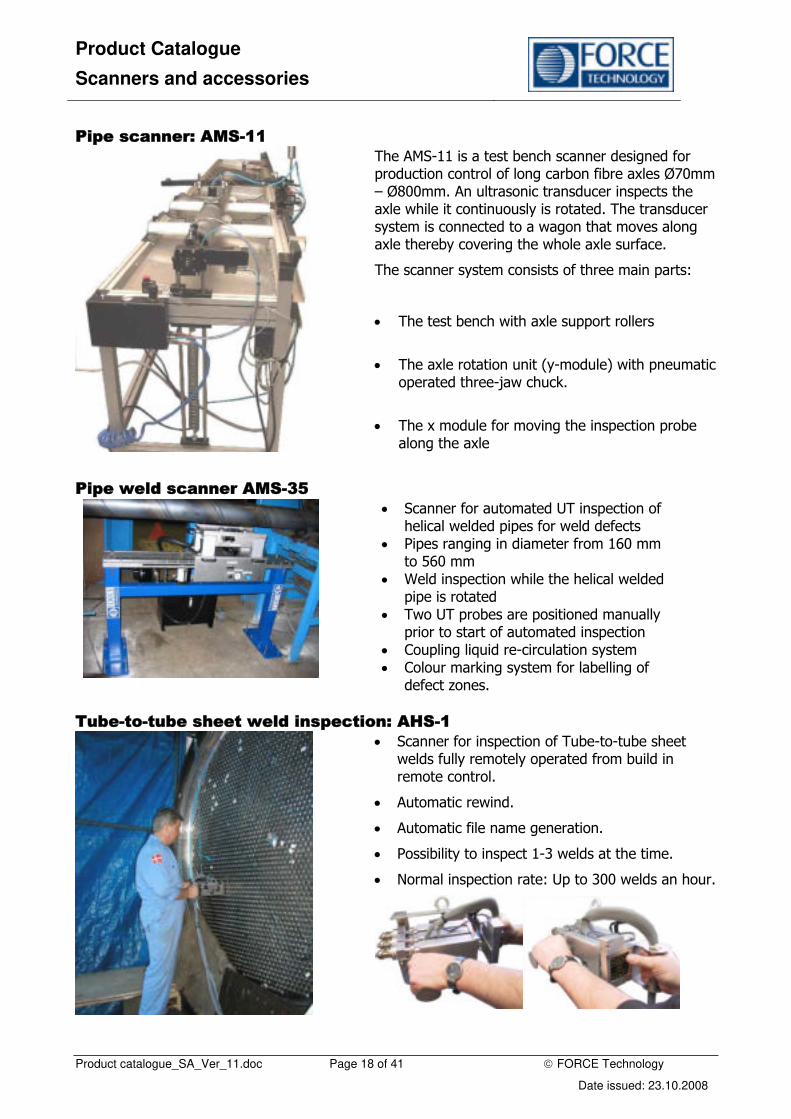
Pipe scanner: AMS-11
The AMS-11 is a test bench scanner designed for production control of long carbon fibre axles Ø70mm – Ø800mm. An ultrasonic transducer inspects the axle while it continuously is rotated. The transducer system is connected to a wagon that moves along axle thereby covering the whole axle surface.
The scanner system consists of three main parts:
• The test bench with axle support rollers
• The axle rotation unit (y-module) with pneumatic operated three-jaw chuck.
• The x module for moving the inspection probe along the axle
Pipe weld scanner AMS-35
• Scanner for automated UT inspection of helical welded pipes for weld defects
• Pipes ranging in diameter from 160 mm to 560 mm
• Weld inspection while the helical welded pipe is rotated
• Two UT probes are positioned manually prior to start of automated inspection
• Coupling liquid re-circulation system • Colour marking system for labelling of
defect zones.
Tube-to-tube sheet weld inspection: AHS-1
• Scanner for inspection of Tube-to-tube sheet welds fully remotely operated from build in remote control.
• Automatic rewind.
• Automatic file name generation.
• Possibility to inspect 1-3 welds at the time.
• Normal inspection rate: Up to 300 welds an hour.

Product Catalogue
Scanners and accessories
Product catalogue_SA_Ver_11.doc Page 19 of 41 © FORCE Technology
Date issued: 23.10.2008
Remote UT inspection of underground storage tanks: AMS-1T
• Dedicated scanner for remote weld inspection and corrosion mapping of underground storage tanks.
• Can be deployed through a 5" hole by use of special deployment tool. • Equipped with small video camera and angle sensor connected to control system for easier
remote operation. • Integrated pneumatic operated release system.
Video simulation available (ams-1t.mpg).
Scanner for underground storage tanks AMS-28
• Scanner for remote weld inspection and corrosion mapping of underground storage tanks.
• Visual inspection of tank surface • Can be deployed through access pipe
with minimum internal diameter of 7” • Equipped with small video camera and
angle sensor connected to control system for easier remote operation.
• Equipped with pneumatic operated arm • Integrated pneumatic operated release
system.
Water jet probe scanner AMS-22
• Automatic XY scanner established by refurbishment and upgrading an outdated installation
• X and Y direction probe speed up to 700 mm/s
• New frame, drives and motors for jet probe motion
• P-scan system 4 with integrated motor control system
• Acceleration and deceleration control to minimize vibration

Product Catalogue
Scanners and accessories
Product catalogue_SA_Ver_11.doc Page 20 of 41 © FORCE Technology
Date issued: 23.10.2008
Automatic track scanner ATS-2
• Scanner for on-site inspection of segments of wind turbine blades or similar structures
• Automatic XY scanner • Two Y modules • Y rails may be curved and supported by
rollers • Track suspended by robust frames
attached to the object with suction cups
Mobile wind turbine blade scanner AMS-20
• Scanner for line inspection of horizontally placed windmill blades
• Probe holder frame with 26 probes • 1.4 metre wide scan sector • Scan velocity up to 6 metre sector length
per minute • The mobile scanner carries batteries,
water pumps, water tank and P-scan system 4 Flex controller unit.
• A single operator controls the mobile scanner.
Wind turbine blade bracing scanner AMS-40
• Scanner fpr inspection of long fibre reinforced blades and beam bracings for wind turbine blades
• Scanner components mounted on a motorized fork lift truck
• XY scans with 4 metre long track scanner unit • Holding system for attachment of track scanner • Tray for calibration plates • Container and pumps fir coupling water • 100% battery operated scanner

Product Catalogue
Scanners and accessories
Product catalogue_SA_Ver_11.doc Page 21 of 41 © FORCE Technology
Date issued: 23.10.2008
FORCE Technology immersion tank scanner solutions
Automatic immersion tank scanner AMS-36
• Scanner for inspection of small solid rotation symmetrical objects for defects
• Tank volume: 15 litres • Two probe holder arms (top and side
probes) • Rotation table for objects
• Automatic scanning when probe starting positions have been set manually
• Motor drives for horizontal movement of the top probe and for vertical movement of the two side probes.
• The scanner can be placed on a table
Automatic immersion tank scanner AMS-30
• Scanner for inspection of objects with great variation in size and shape
• Tank volume: 2400 litre
• Tank floor with lift table with turn table
• Five axes scanning arm
• Programmable track line for scanning arm
• Scanning of multiple objects can be programmed
• Special scanner devices for examination of embedded straight or curved pipes.

Product Catalogue
Scanners and accessories
Product catalogue_SA_Ver_11.doc Page 22 of 41 © FORCE Technology
Date issued: 23.10.2008
Automatic immersion tank scanner AMS-38
• Scanner for inspection of rotation symmetric ring shaped objects
• Tank volume: 5000 litre
• Roller bed hold and rotate objects
• Two scanner arms with probe holders
• XZ movement and tilt of probe holders
• Library with programs for automated inspection of various components
• System can generate scan programs from CAD-drawings
Automatic immersion tank scanner AMS-43
• Inspection of non-symmetrical objects
• Scanner for inspection of rotation symmetric objects
• Tank volume: 450 litre
• Rotation table installed in bottom plate
• Probe tilt, skew and XYZ movement
• System software can generate scan programs from CAD-3D drawings of object
• Scan data visualized in 3D images

Product Catalogue
Scanners and accessories
Product catalogue_SA_Ver_11.doc Page 23 of 41 © FORCE Technology
Date issued: 23.10.2008
Wind turbine shaft scanner AMS-32
• Scanner for inspection of wind turbine shafts with flange for cracks and other defects
• Shaft rotated in roller bed during inspection
• Two probe holder systems scan flange and shaft in axial direction
• Three probes holder systems scan shaft and flange in direction perpendicular ti axis
Suction roll sheet scanner AMS 33
• Scanner for on-site service inspection of suction roll sheets for cracks and other defects between suction holes
• Use ultrasound and eddy current transducers
• Internal sheet diameters ranging from 570 mm to 1700 mm
Automatic ring scanner AMS-37
• Portable XY wheel scanner for inspection of forged rings
• Scanner moves along the ring during scanning
• Y module for top side of ring and Y module for side of ring
• Each Y module with two probe holders • Scanner weight: 24 kg

Product Catalogue
Scanners and accessories
Product catalogue_SA_Ver_11.doc Page 24 of 41 © FORCE Technology
Date issued: 23.10.2008
Brazed joint scanner AMS-39
• Scanner for inspection of brazed joints between pipe and fittings mounted on the pipe end
• Water jet technique with one probe outside and the other probe inside the pipe
• Usable for pipes with diameter ranging from 6 mm to 60 mm.
• Automatic operation while the probe system is turned along the circumference of the joint
• The probe system can in an automatic scan mode be moved along the pipe axis while it is rotated
• The scanner can be placed on a table

Product Catalogue
Scanners and accessories
Product catalogue_SA_Ver_11.doc Page 25 of 41 © FORCE Technology
Date issued: 23.10.2008
Modular scanner system Inspection of objects with complex geometry, difficult access, or special inspection requirements will often lead to the need for a special scanner. To simplify design, manufacturing, CE-marking and service of scanners, FORCE Technology has developed a flexible modular scanner system. The system consists of interface and control electronics boxes, motors with or without integrated driver electronics (2-750W DC motors), output gear units, Y-module, sensors and others components needed for building a scanner for NDT inspection.
Example on configuration of modular scanner components with P-scan motor controller:
User Interface and Scanner control (P-scan system)
Control PC with software
Power supply and interface box
P-scan UT system or separate motor controller
Remote control
Water pump
Scanner main cable
Control and motor driver electronics
Emergency stop switch
Master module Link Module
Motor Driver Unit
Motor and control sensors
Angle sensor
Free wheel encoder
Standard Motors
Large motor
(750W-220V)
External output gears
Angle gear
Straight gear
Output modules
Telescopic Y-module
Y-module
Magnetic wheel set
Measurement sensors
UT-probe with holder
Video camera / light
As a standard, the scanner system is controlled through the FORCE Technology P-scan motor controller system; a Windows based control software. The use of this controller in combination

Product Catalogue
Scanners and accessories
Product catalogue_SA_Ver_11.doc Page 26 of 41 © FORCE Technology
Date issued: 23.10.2008
with scanner mounted motor driver electronics reduces the scanner power and control cabling to a single Ø12mm cable.
As an option, interface to other motor controller systems can be delivered.
General description
To obtain flexibility, the basic electronic components of the scanner system are built as individual modules (master, link, driver, and motor modules) containing control and communication electronics. The modules are building units which are assembled to the needed scanner from specially designed mechanical components, and together with the selected inspection sensors they can perform the desired inspection.
The electronic boxes and the motors are connected through external cables. For simple assembly and service, the motors, output gears, and output modules are connected with couplings.
The next page shows configuration of modular scanner components with P-scan motor controller.
Interface electronics to P-scan systems
Small Remote Control RCU-4
• Small remote control that can be mounting on scanner or hand held
• Direct Interface to P-scan motorcontroller trhough link connector.
• Keyboard can be delived to fit actual scanner configuration.
Specifications: RCU-4
Electronics Keyboard with 9 buttons with maximum 17 funktions.
Software Requires dedicated driver in P-scan control software.
Connectors Link connector to MST-3 / LIM-2 or direct to P-scan unit.
Housing Anodised aluminium
IP code 55
Dimensions L / W / H: 119 / 74 / 26.5
Product Catalogue
Scanners and accessories
Product catalogue_SA_Ver_11.doc Page 27 of 41 © FORCE Technology
Date issued: 23.10.2008
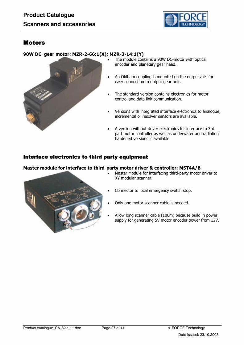
Motors
90W DC gear motor: MZR-2-66:1(X); MZR-3-14:1(Y)
• The module contains a 90W DC-motor with optical encoder and planetary gear head.
• An Oldham coupling is mounted on the output axis for easy connection to output gear unit.
• The standard version contains electronics for motor control and data link communication.
• Versions with integrated interface electronics to analogue, incremental or resolver sensors are available.
• A version without driver electronics for interface to 3rd part motor controller as well as underwater and radiation hardened versions is available.
Interface electronics to third party equipment
Master module for interface to third-party motor driver & controller: MST4A/B
• Master Module for interfacing third-party motor driver to XY modular scanner.
• Connector to local emergency switch stop.
• Only one motor scanner cable is needed.
• Allow long scanner cable (100m) because build in power supply for generating 5V motor encoder power from 12V.
Product Catalogue
Scanners and accessories
Product catalogue_SA_Ver_11.doc Page 28 of 41 © FORCE Technology
Date issued: 23.10.2008
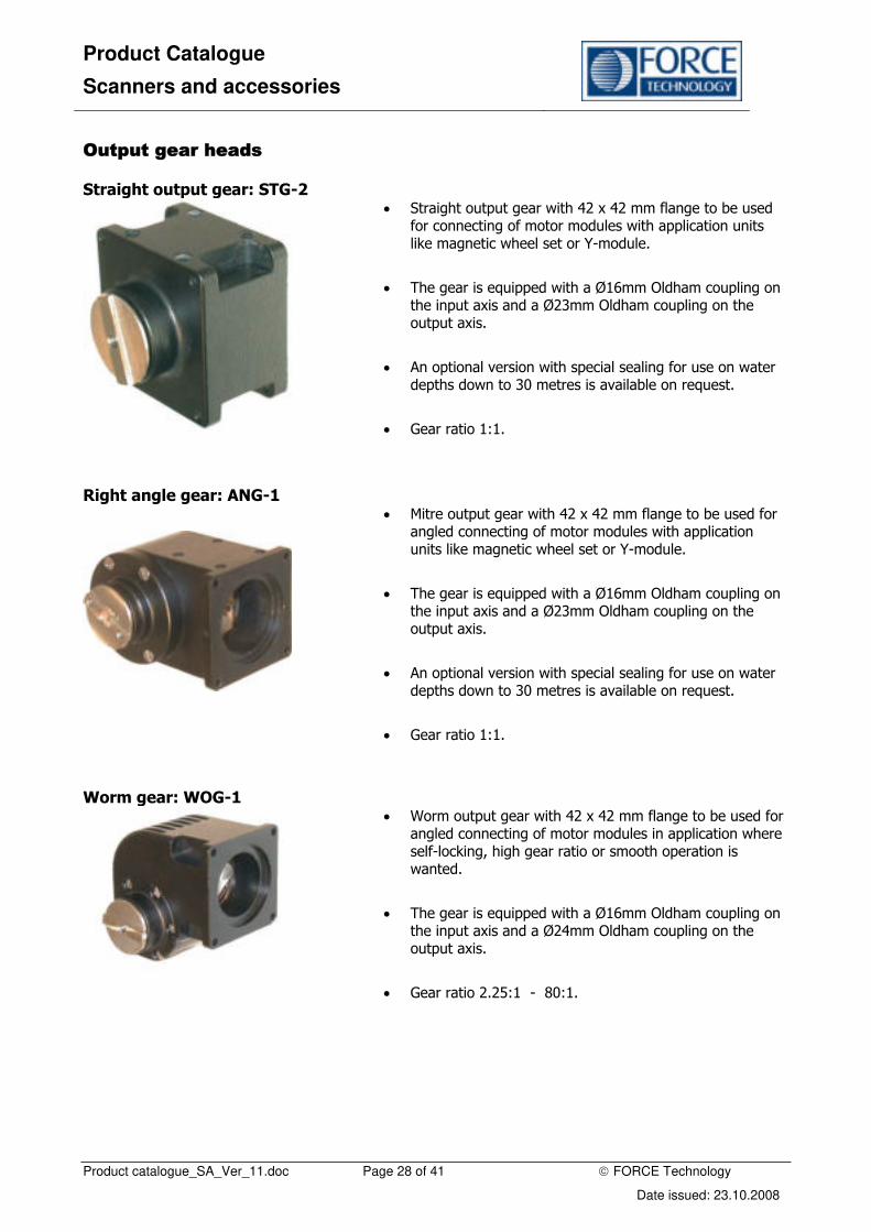
Output gear heads
Straight output gear: STG-2
• Straight output gear with 42 x 42 mm flange to be used for connecting of motor modules with application units like magnetic wheel set or Y-module.
• The gear is equipped with a Ø16mm Oldham coupling on the input axis and a Ø23mm Oldham coupling on the output axis.
• An optional version with special sealing for use on water depths down to 30 metres is available on request.
• Gear ratio 1:1.
Right angle gear: ANG-1
• Mitre output gear with 42 x 42 mm flange to be used for angled connecting of motor modules with application units like magnetic wheel set or Y-module.
• The gear is equipped with a Ø16mm Oldham coupling on the input axis and a Ø23mm Oldham coupling on the output axis.
• An optional version with special sealing for use on water depths down to 30 metres is available on request.
• Gear ratio 1:1.
Worm gear: WOG-1
• Worm output gear with 42 x 42 mm flange to be used for angled connecting of motor modules in application where self-locking, high gear ratio or smooth operation is wanted.
• The gear is equipped with a Ø16mm Oldham coupling on the input axis and a Ø24mm Oldham coupling on the output axis.
• Gear ratio 2.25:1 - 80:1.
Product Catalogue
Scanners and accessories
Product catalogue_SA_Ver_11.doc Page 29 of 41 © FORCE Technology
Date issued: 23.10.2008
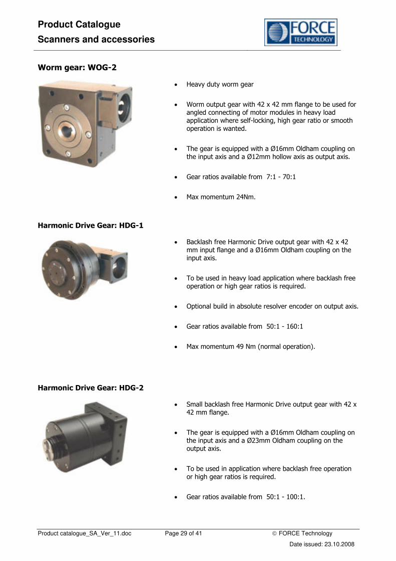
Worm gear: WOG-2
• Heavy duty worm gear
• Worm output gear with 42 x 42 mm flange to be used for angled connecting of motor modules in heavy load application where self-locking, high gear ratio or smooth operation is wanted.
• The gear is equipped with a Ø16mm Oldham coupling on the input axis and a Ø12mm hollow axis as output axis.
• Gear ratios available from 7:1 - 70:1
• Max momentum 24Nm.
Harmonic Drive Gear: HDG-1
• Backlash free Harmonic Drive output gear with 42 x 42 mm input flange and a Ø16mm Oldham coupling on the input axis.
• To be used in heavy load application where backlash free operation or high gear ratios is required.
• Optional build in absolute resolver encoder on output axis.
• Gear ratios available from 50:1 - 160:1
• Max momentum 49 Nm (normal operation).
Harmonic Drive Gear: HDG-2
• Small backlash free Harmonic Drive output gear with 42 x 42 mm flange.
• The gear is equipped with a Ø16mm Oldham coupling on the input axis and a Ø23mm Oldham coupling on the output axis.
• To be used in application where backlash free operation or high gear ratios is required.
• Gear ratios available from 50:1 - 100:1.

Product Catalogue
Scanners and accessories
Product catalogue_SA_Ver_11.doc Page 30 of 41 © FORCE Technology
Date issued: 23.10.2008
Output modules
Y-module rail system: YMO-2
• Standard Y-module rail system incl. tilt adaptor on slide.
• The rail can be delivered in different lengths (standard length 350 & 510mm , stroke equal to Y-module rail length minus slide length).
• Curved rails and a slide without tilt adapter can be delivered as an option.
Pictures: Y-module.
Rear view of Y-module showing the three main components of the Y-module: the transmission unit with open end timing belt; the slide with integrated belt tightener and the Y-module rail.
70 mm slide with integrated tilt adapter.
Options: Y-module YMO-2
Long slide:
For heavy-duty inspection with multiple probes a 100mm long slide is available. Slide can only be used on straight
Y-module rails.
Mechanical probe lifting device:
Mechanical probelifting device that can be mounted on long 100 mm slide. Operated by Y-slide movement. No extra cabeling or control system is necessary. Reduces Y-module stroke 50mm and has a 45 mm lifting height. Device equipped with bracket for standard probe rail. Can be used with up to six probe at the same time.

Product Catalogue
Scanners and accessories
Product catalogue_SA_Ver_11.doc Page 31 of 41 © FORCE Technology
Date issued: 23.10.2008
Long Y-module rails:
Y-module rails can be delivered in lengths up to 1 m in steps of 20 mm. Optional the rails can be delivered with machining and brackets that allows assembling rails (straight and curved).
Curved Y-module rail:
• Standard curved rails with 90° and 180° stroke and centre line radius150, 200, 250 and 300 mm.
• Customised curved rails (10° - 300°) with radius R >150 mm.
• Used together with standard 70 mm Y-module slide and transmission unit.
• For better inspection of welds near curved surfaces.
• For corrosion mapping of pipes and pipe bends.
2.1.1 Telescopic Y-module: YMO-2 • Special Y-module for use in areas with limited space.
• Stroke ± 220 mm.
• Minimum width 160 mm.
• Interface to standard output gear coupling.
Magnetic wheel set: MAW-3 (LH + RH)
• Wheel set with rare-earth permanent magnetic wheels.
• Interface to standard modular scanner output gear head.
• Integrated lifting system.
• Magnetic wheels for special applications can be delivered as an option.

Product Catalogue
Scanners and accessories
Product catalogue_SA_Ver_11.doc Page 32 of 41 © FORCE Technology
Date issued: 23.10.2008
Control and measurement sensors
Inclinometer. Guiding unit 120°: ICM-2
• Inclinometer unit containing an angle sensor and amplifier electronics for measuring orientations relative to vertical.
• The unit is interfaced to scanner data link through position input connector on the MTR-2 motor module.
• Measurement range -25° to 115° (horizontal = 0°) in a vertical or near vertical orientated plane.
External incremental encoder: ENC-6-1 • External encoder ENC-6-1 containing optically incremental
encoder driven by a wheel. The ENC-6-1 is used when there is a risk for wheel slip on driving wheels and correctly moved distance must be measured.

Product Catalogue
Scanners and accessories
Product catalogue_SA_Ver_11.doc Page 33 of 41 © FORCE Technology
Date issued: 23.10.2008
Scanner control The standard controller for the manipulator is the P-scan motor controller integrated in the PSP-4 ultrasonic acquisition system. The standard user interface is the PC Windows based PS-4 software belonging to the P-scan system.
As an option, most scanners can be delivered with interface to other motor controllers and / or inspection systems.
P-scan interface
System communication A diagram of the standard scanner system power and communication cabling is shown below:

Product Catalogue
Scanners and accessories
Product catalogue_SA_Ver_11.doc Page 34 of 41 © FORCE Technology
Date issued: 23.10.2008
The master module controls both the communication in the local network and the communication between the network and the base station (a scanner master controller or a FORCE Technology PSP-4 ultrasonic acquisition unit). The communication between the base station and the control computer (PC with Windows or Unix-workstation) runs on a standard Ethernet connection.
Up to 20 modules can be connected to the network without needing extra cable between the base station and the scanner.
System configuration To simplify the configuration, a graphics configuration program running under Windows 95/98 is part of the modular scanner system. The program is used for setting network addresses for motor modules and external sensors, motor driver and gear parameters plus calibration and zero point set-ups of external sensors. The program simplifies optimization of velocities, accelerations, filter constants and overload parameters for the individual scanner axis.

Product Catalogue
Scanners and accessories
Product catalogue_SA_Ver_11.doc Page 35 of 41 © FORCE Technology
Date issued: 23.10.2008
Scanner controllers
Three versions of the software for control of the modular scanner system are available.
Depending on the scanner complexity and the requirements to scan pattern, the actual scanner control software is selected. The three versions are:
Generic scanner controller for XY scanner
If the scanner is a simple XY scanner
performing meander-scanning pattern,
it can be controlled from a simple,
generic scanner controller program
belonging to the system.
Dedicated scanner controller
If more user-friendliness is required or the scanner requires simultaneous control of more motors and sensor inputs, a dedicated scanner driver / user interface is necessary.

Product Catalogue
Scanners and accessories
Product catalogue_SA_Ver_11.doc Page 36 of 41 © FORCE Technology
Date issued: 23.10.2008
Scanner controller with PC interface
If no ultrasonic acquisition system is required in relation to the use of the scanner system, the
P-scan motor controller with user interface program can be delivered as a separate unit without UT-system.
3’rd party UT system
X and Y signal position cables
PSP-4C Motor Controller
Control PC
Scanner
Emergency stop
Free wheel encoder
Motor
Motor
The scanner control interface and the modular flexibility will be exactly the same as if the scanner was connected to a P-scan ultrasonic system.

Product Catalogue
Scanners and accessories
Product catalogue_SA_Ver_11.doc Page 37 of 41 © FORCE Technology
Date issued: 23.10.2008
Third-party controller
For interfacing a third-party motor controller system, many of the scanners can be delivered with motor unit with connector for the motor power and the motor incremental encoder.
For PC or other systems using a motor controller with +/- 10V-control signal a motor driver unit for a XY scanner is available. It is delivered with power supply and scanner interface to Master Module MST-4A and control and encoder signal interface to motor controller.
MPA-1 Motor Power Amplifier
3’rd party UT system
X and Y signal position cables
X and Y control signals
Scanner
Emergency stop
Free wheel encoder
Motor
Motor
Product Catalogue
Scanners and accessories
Product catalogue_SA_Ver_11.doc Page 38 of 41 © FORCE Technology
Date issued: 23.10.2008
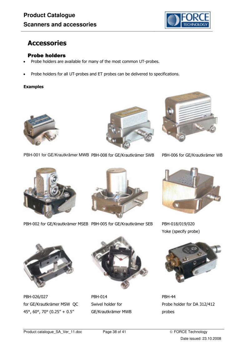
Accessories
Probe holders • Probe holders are available for many of the most common UT-probes.
• Probe holders for all UT-probes and ET probes can be delivered to specifications.
Examples
PBH-001 for GE/Krautkrämer MWB PBH-008 for GE/Krautkrämer SWB PBH-006 for GE/Krautkrämer WB
PBH-002 for GE/Krautkrämer MSEB PBH-005 for GE/Krautkrämer SEB PBH-018/019/020
Yoke (specify probe)
PBH-026/027
for GE/Krautkrämer MSW QC
45°, 60°, 70° (0.25” + 0.5”
PBH-014
Swivel holder for
GE/Krautkrämer MWB
PBH-44
Probe holder for DA 312/412
probes

Product Catalogue
Scanners and accessories
Product catalogue_SA_Ver_11.doc Page 39 of 41 © FORCE Technology
Date issued: 23.10.2008
TOFD bar with probe yokes
(specify probes)
Multi probe set-up for production control
PBH-21 special rotational
probe holder for round and
square probes up to
40x40mm
Probe holder arms
Springloaded probe holder arms: PHA-25/50/75
• To secure proper contact between probes and inspection object, the probe holder with probe is mounted on a spring-loaded arm fastened to the scanner.
• Several versions and sizes of spring-loaded arms are available.
• PHA are equipped with a snap coupling for fast and easy change of probes.
• Stroke 20, 45 and 68 mm.

Product Catalogue
Scanners and accessories
Product catalogue_SA_Ver_11.doc Page 40 of 41 © FORCE Technology
Date issued: 23.10.2008
Special probe holder arms
• Special probeholder arm / probe holder systems are manufactured to specifications whether it is small size, extra high load etc.
As example; here a very compact probe holder system is shown.
Probe rails:
Probe rails. PBH-1 • Probe rails in assorted length
• Standard length 250mm, 500mm, 1000mm
Probe rails: PBR-2-90
• Set of 90° probe rail displacement
Probe Bar:
Bar for dual probe set-up: PBD-1
• Bar for dual probe set-up (probes in parallel).

Product Catalogue
Scanners and accessories
Product catalogue_SA_Ver_11.doc Page 41 of 41 © FORCE Technology
Date issued: 23.10.2008
Coupling media pumps
Peristaltic water pump: DCP-1
• Peristaltic pump for pumping coupling media to ultrasonic transducers.
• It is connected directly to the scanner data link, and the water flow (speed of pump) is controlled from the scanner control software.
• The pump is self-priming and can be used both for water, jelly and glycerine.
• It is quite insensitive to small dirt particles in the pump media.
Gear Pump: DCP-4
• It is connected directly to the scanner data link, and
the water flow (speed of pump) is controlled from the scanner control software.
• The pump is self-priming • Pumping height up to 25 m with a flow rate ranging
1.5 -1.8 l/min.


![Hkw] ?kk] Qk]](https://img.pdfslide.us/doc/110x75/5a8368347f8b9a38478ebcef/hkw-kk-qk-k-s-ks-hkk-hkh-hkw-kk-qk-k-gem-000611-mrigashira-3.jpg)