Embed Size (px)
Citation preview

P ROGRAMMING M ANUAL September 2009Document #: LT-2011 Rev.2
WARNING : This manual contains information on limitations regarding product use and function and information on the limitations as to liability of the manufacturer. The entire manual should be read carefully.
M R - 2 9 0 0 Fire Alarm Control Unit

MR-2900 Programming Manual
Table of Contents1.0 Operation and Programming Concepts ......................................................................... 1
1.1 General Comments ....................................................................................................... 11.2 Networks ....................................................................................................................... 21.3 Addressable Devices .................................................................................................... 41.4 Releasing Service ......................................................................................................... 71.5 Resetting 4-Wire Detectors ........................................................................................... 8
2.0 Editing MHI Databases ..................................................................................................... 92.1 General Comments ....................................................................................................... 92.2 System Window ............................................................................................................ 102.3 Switches Window .......................................................................................................... 132.4 Groups Window ............................................................................................................. 142.5 Panel Window ............................................................................................................... 162.6 Circuits and Devices Windows ...................................................................................... 302.7 Internal Circuits Window ............................................................................................... 342.8 Relate Window .............................................................................................................. 35
3.0 LCD Programming ............................................................................................................ 373.1 General Comments ....................................................................................................... 373.2 Clock ............................................................................................................................. 383.3 Common Relays ............................................................................................................ 383.4 Switches ........................................................................................................................ 383.5 Battery ........................................................................................................................... 393.6 Conventional ................................................................................................................. 393.7 Addressable .................................................................................................................. 393.8 Archive .......................................................................................................................... 413.9 Relays ........................................................................................................................... 413.10 Ports ............................................................................................................................ 413.11 Alarm List .................................................................................................................... 443.12 Passcode .................................................................................................................... 443.13 Memory ....................................................................................................................... 443.14 Buzzer ......................................................................................................................... 44
4.0 Appendix A: Condition Codes and Zone Numbers ....................................................... 455.0 Appendix B: Stand-by Battery Calculation .................................................................... 50
5.1 General ......................................................................................................................... 505.2 Sample Calculation ....................................................................................................... 51
6.0 Appendix C: Service Terminal ........................................................................................ 526.1 Control Unit ................................................................................................................... 526.2 Addressable Module ..................................................................................................... 57
7.0 Appendix D: Table of Reporting Codes ......................................................................... 60
i

MR-2900 Programming Manual
List of Figures & Tables
Figure 1: Typical Network Layout ........................................................................................ 2Figure 2: Single Network Break .......................................................................................... 3Figure 3: Panel Removed From Network ............................................................................ 4Figure 4: 4-Wire Device Wiring (Typical) ............................................................................ 8Figure 5: System Window ................................................................................................... 10Figure 6: Switches Window ................................................................................................. 13Figure 7: Groups Window ................................................................................................... 14Figure 8: Panel Window ...................................................................................................... 16Figure 9: IDs Supervised ..................................................................................................... 18Figure 10: Annunciator Panel Window ................................................................................ 18Figure 11: Output Dialog ..................................................................................................... 19Figure 12: Options Dialog ................................................................................................... 21Figure 13: Default Key Assignments ................................................................................... 23Figure 14: Fixed Key Assignments ..................................................................................... 23Figure 15: Dialer Settings .................................................................................................... 25Figure 16: Dialer Configuration 1 ........................................................................................ 26Figure 17: Dialer Configuration 2 ........................................................................................ 27Figure 18: Call Directions .................................................................................................... 28Figure 19: Zone Data .......................................................................................................... 29Figure 20: Circuits Window ................................................................................................. 29Figure 21: Circuits Window ................................................................................................. 30Figure 22: Devices Window ................................................................................................ 30Figure 23: Copy Dialog Box ................................................................................................ 33Figure 24: Internal Circuits Window .................................................................................... 34Figure 25: Relate Window ................................................................................................... 35Figure 26: Typical Menu ...................................................................................................... 37Figure 27: Typical Selector ................................................................................................. 37
Table 1: Automatic Contact ID/SIA Reporting Codes ......................................................... 60Table 2: Contact ID Zone Alarm/Restore Event Codes ...................................................... 61Table 3: SIA Format Automatic Zone Alarm/Restore Codes .............................................. 61
iii

MR-2900 Programming Manual
1.0 Operation and Programming Concepts
Warnings: Before Programming
1. All applicable codes and standards should be considered when programming the ControlUnit.
2. The Control Unit continues to monitor input circuits and devices and acts according to thecurrent program settings if an alarm is received while it is being programmed.
3. Loading a new database erases the current database before loading the new database. Ifthe new database is not loaded after the erasure, the panel will not operate.
4. The database internal revision number included must match the number required by theMR2 program, otherwise a Database Mismatch trouble condition is generated. Thiscondition disables the panel until a correct MR2 program is loaded.
5. The database must be completely loaded for it to be considered valid. The program keepstrack if the last database load was valid/complete or not. An invalid database load disablesthe panel until a valid database load is done.
1.1 General CommentsThere are two different programs available for use in the Control Panel:
• The MR1 program only works with a stand alone panel and conventional input circuits. Allprogramming is done through the LCD and keypad. This is not discussed here.
• The MR2 program handles all variations. Input circuit programming is done from thedatabase, while system parameters are programmed from the LCD and keypad. Theprograms and their port 3 usages are: MR2-x: old SE 2000 protocol; MR2-xA: MR-2614annunciator, MR-2644 annunciator, MR-2801-MR Reverse Polarity module and MRDLDialer. MR2-xB: new SE 2000 protocol (device level); MR2-xG: GRID; MR2-xE: MV-2700Voice Evacuation panel. MR2-7y programs are for MR-2931 based systems and MR2-3yprograms are for MR-2921 based systems.
Due to programming and hardware limitations, units using the MR-2901C and MR-2921 maincircuit boards may not have some of the options that are listed here.
The MR2 program uses a database for input circuit programming. This database includes theconventional circuit definitions, addressable devices on-line, and the Zone LEDs, Bells, Releasers,Functions Relays and Control Modules activated by the conventional circuits and addressabledevices. This database is created and downloaded from an IBM compatible computer using theModul-R Human Interface (MHI) program. Refer to the Modul-R Human Interface User Guide forinstructions on downloading the database.
This manual is for database version 22.
The use of Port 3 on the panel is handled by loading different versions of the operating program.Each different protocol has its own operating program. If an incorrect operating program isdetected, a Miscellaneous Trouble is generated, but the panel will continue to work except for thePort 3 functions.
Note: All communications are stopped during the database load. This will cause a trouble to be recorded by those units that are normally communicating with the panel.
1
MR-2900 Programming Manual
1.2 Networks
General
The MR-2900 can be incorporated into a network including other MR-2900 panels, MR-2200panels and MR-2944 annunciators. Though up to 254 panels and annunciators can be supportedby the network, such a network would probably be too large to properly maintain. The network canbe setup for single building or multiple building operation.
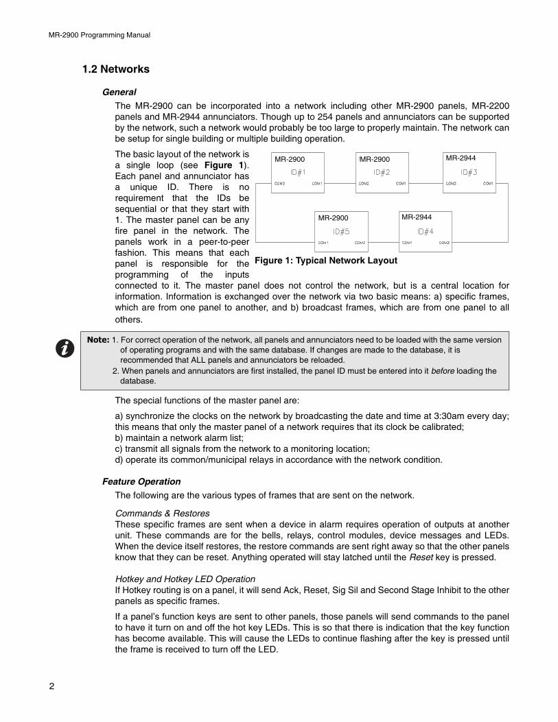
The basic layout of the network isa single loop (see Figure 1).Each panel and annunciator hasa unique ID. There is norequirement that the IDs besequential or that they start with1. The master panel can be anyfire panel in the network. Thepanels work in a peer-to-peerfashion. This means that eachpanel is responsible for theprogramming of the inputsconnected to it. The master panel does not control the network, but is a central location forinformation. Information is exchanged over the network via two basic means: a) specific frames,which are from one panel to another, and b) broadcast frames, which are from one panel to allothers.
The special functions of the master panel are:
a) synchronize the clocks on the network by broadcasting the date and time at 3:30am every day;this means that only the master panel of a network requires that its clock be calibrated;b) maintain a network alarm list;c) transmit all signals from the network to a monitoring location;d) operate its common/municipal relays in accordance with the network condition.
Feature Operation
The following are the various types of frames that are sent on the network.
Commands & RestoresThese specific frames are sent when a device in alarm requires operation of outputs at anotherunit. These commands are for the bells, relays, control modules, device messages and LEDs.When the device itself restores, the restore commands are sent right away so that the other panelsknow that they can be reset. Anything operated will stay latched until the Reset key is pressed.
Hotkey and Hotkey LED OperationIf Hotkey routing is on a panel, it will send Ack, Reset, Sig Sil and Second Stage Inhibit to the otherpanels as specific frames.
If a panel’s function keys are sent to other panels, those panels will send commands to the panelto have it turn on and off the hot key LEDs. This is so that there is indication that the key functionhas become available. This will cause the LEDs to continue flashing after the key is pressed untilthe frame is received to turn off the LED.
Note: 1. For correct operation of the network, all panels and annunciators need to be loaded with the same version of operating programs and with the same database. If changes are made to the database, it is recommended that ALL panels and annunciators be reloaded.
2. When panels and annunciators are first installed, the panel ID must be entered into it before loading the database.
MR-2900 MR-2900
MR-2900
MR-2944
MR-2944
Figure 1: Typical Network Layout
2
MR-2900 Programming Manual
Time/Date ChangeThis broadcast frame is sent by a panel or annunciator if the time or date is changed. The masterpanel also will send both a date and time change frame at 3:30am every day to synchronize all theclocks in the network.
Manual Switch OperationIf the state of any of the 16 software switches is changed manually at any panel, this change isbroadcast to all other panels. The software switches are a system resource.
Network RebootIf a Network Reset command is initiated at a panel, it is broadcast normally and then the panel willreboot itself. Upon receiving the Network Reboot command, a panel will pass it on to the nextpanel and then reboot itself. This has the affect of causing all the panels to reboot simultaneously.
Network VerifyNetwork Verify is the process by which the master panel queries the rest of the network todetermine on-line status. Each panel will respond to the network verify request. The user can alsorequest a Network Verify at any time from any panel in the network.
Network Communications
Information is sent across the network in frames. There are two types of frames: specific andbroadcast. Specific frames are sent from one unit to another. Broadcast frames are sent from oneunit to all others.
Specific FramesSpecific frames deal with information generated at one panel and required at another. It is passedfrom panel to panel until it reaches its destination. Each panel has a list as to which port to sendframes from to reach all other panels through the fewest number of panels. Since networks willgenerally have all communications links running at the same baud rate, this is generally theshortest time as well.
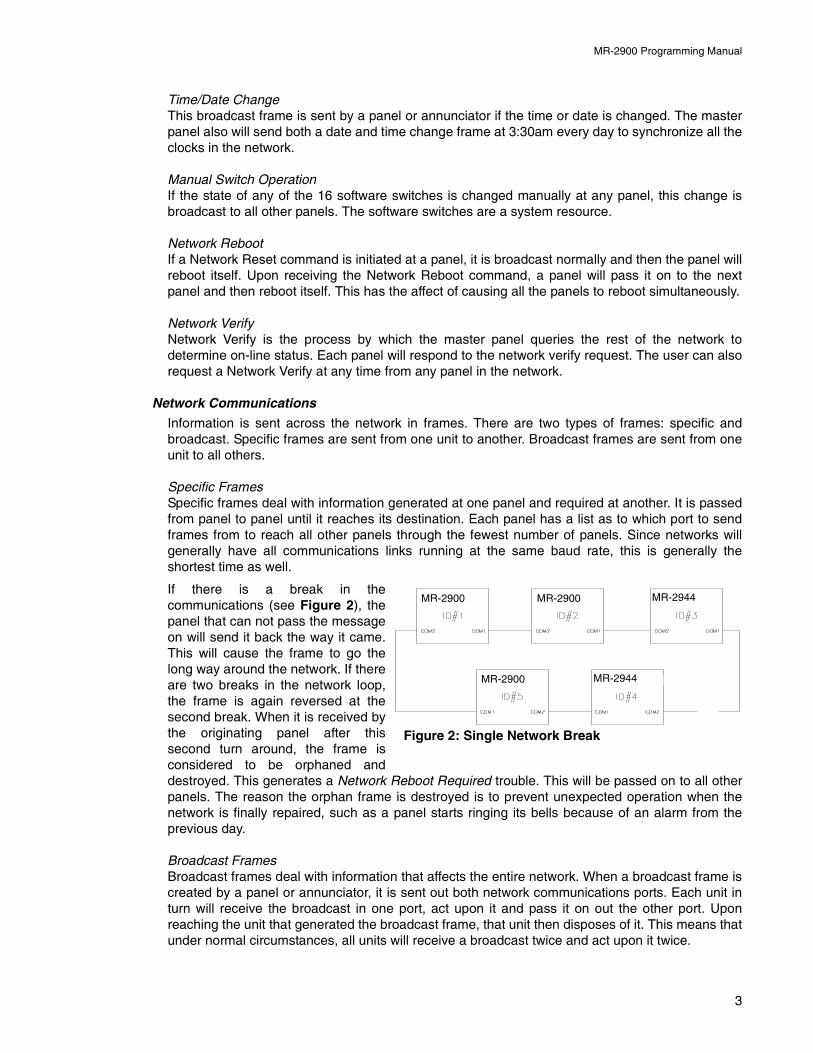
If there is a break in thecommunications (see Figure 2), thepanel that can not pass the messageon will send it back the way it came.This will cause the frame to go thelong way around the network. If thereare two breaks in the network loop,the frame is again reversed at thesecond break. When it is received bythe originating panel after thissecond turn around, the frame isconsidered to be orphaned anddestroyed. This generates a Network Reboot Required trouble. This will be passed on to all otherpanels. The reason the orphan frame is destroyed is to prevent unexpected operation when thenetwork is finally repaired, such as a panel starts ringing its bells because of an alarm from theprevious day.
Broadcast FramesBroadcast frames deal with information that affects the entire network. When a broadcast frame iscreated by a panel or annunciator, it is sent out both network communications ports. Each unit inturn will receive the broadcast in one port, act upon it and pass it on out the other port. Uponreaching the unit that generated the broadcast frame, that unit then disposes of it. This means thatunder normal circumstances, all units will receive a broadcast twice and act upon it twice.
Figure 2: Single Network Break
MR-2900 MR-2900
MR-2900
MR-2944
MR-2944
3
MR-2900 Programming Manual
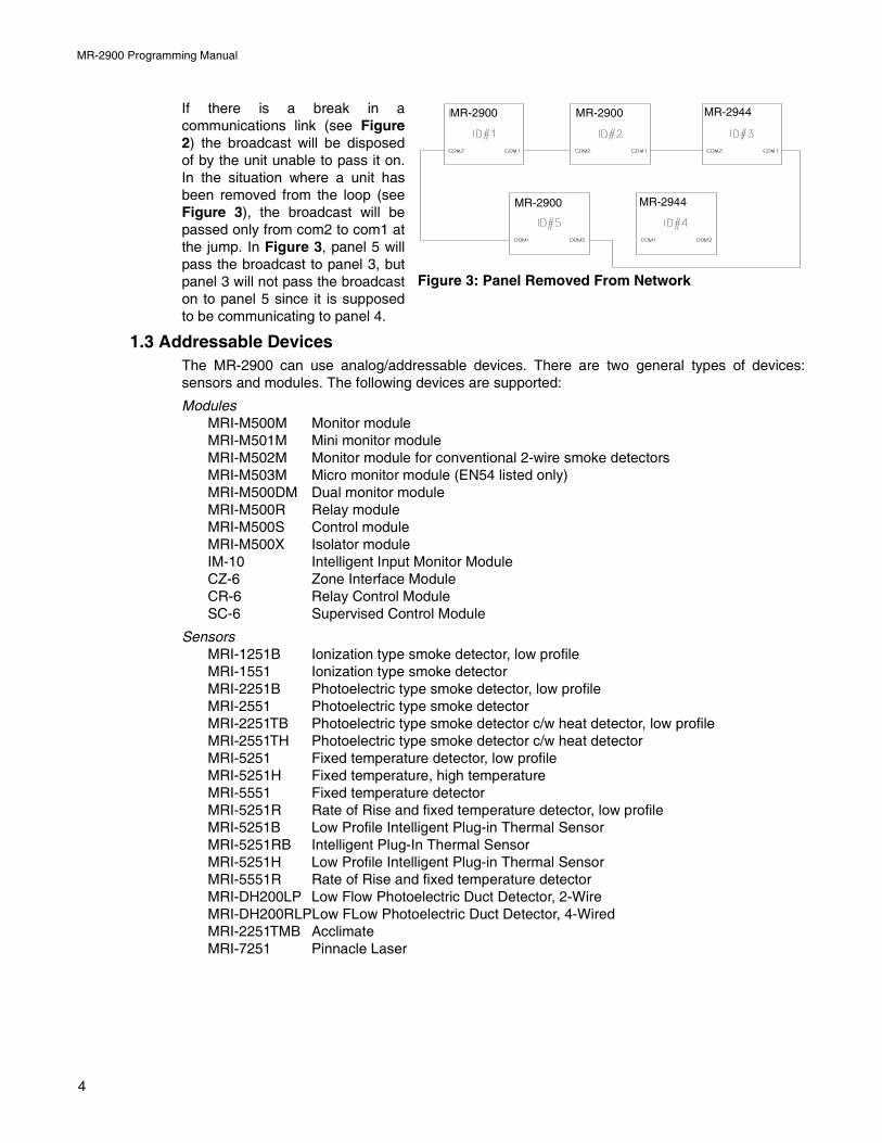
If there is a break in acommunications link (see Figure2) the broadcast will be disposedof by the unit unable to pass it on.In the situation where a unit hasbeen removed from the loop (seeFigure 3), the broadcast will bepassed only from com2 to com1 atthe jump. In Figure 3, panel 5 willpass the broadcast to panel 3, butpanel 3 will not pass the broadcaston to panel 5 since it is supposedto be communicating to panel 4.
1.3 Addressable DevicesThe MR-2900 can use analog/addressable devices. There are two general types of devices:sensors and modules. The following devices are supported:
ModulesMRI-M500M Monitor moduleMRI-M501M Mini monitor moduleMRI-M502M Monitor module for conventional 2-wire smoke detectorsMRI-M503M Micro monitor module (EN54 listed only)MRI-M500DM Dual monitor moduleMRI-M500R Relay moduleMRI-M500S Control moduleMRI-M500X Isolator moduleIM-10 Intelligent Input Monitor ModuleCZ-6 Zone Interface ModuleCR-6 Relay Control ModuleSC-6 Supervised Control Module
SensorsMRI-1251B Ionization type smoke detector, low profileMRI-1551 Ionization type smoke detectorMRI-2251B Photoelectric type smoke detector, low profileMRI-2551 Photoelectric type smoke detectorMRI-2251TB Photoelectric type smoke detector c/w heat detector, low profileMRI-2551TH Photoelectric type smoke detector c/w heat detectorMRI-5251 Fixed temperature detector, low profileMRI-5251H Fixed temperature, high temperatureMRI-5551 Fixed temperature detectorMRI-5251R Rate of Rise and fixed temperature detector, low profileMRI-5251B Low Profile Intelligent Plug-in Thermal SensorMRI-5251RB Intelligent Plug-In Thermal SensorMRI-5251H Low Profile Intelligent Plug-in Thermal SensorMRI-5551R Rate of Rise and fixed temperature detectorMRI-DH200LP Low Flow Photoelectric Duct Detector, 2-WireMRI-DH200RLPLow FLow Photoelectric Duct Detector, 4-WiredMRI-2251TMB AcclimateMRI-7251 Pinnacle Laser
Figure 3: Panel Removed From Network
MR-2900 MR-2900
MR-2900
MR-2944
MR-2944
4
MR-2900 Programming Manual
The MRI-M500M, MRI-M500DM, MRI-M501M, MRI-M502M and MRI- M503M monitor modules allappear the same to the MR-2900. This allows for the easy substitution of devices. TheMRI-M501M and MRI-M503M modules are intended for mounting inside the back box of aconventional contact device. The MRI-M500M, MRI-M500DM and MRI-M502M require backboxes for mounting.
The MRI-M500DM dual monitor module has two Class (Style) B input circuits. The first input usesthe address dialled into the module and the second uses that address plus 1. That is, if the dialsare set for address 34, the monitor modules to be programmed into MHI are at addresses 134 and135.
The MRI-M502M monitor module can be used for monitoring up to 20 System Sensor two-wiresmoke detectors. The module requires a separate 24 VDC supply to power the smoke detectors.Also, some external means of resetting the power must be provided since the module cannot resetthe detectors. This can be accomplished with one of the general purpose relays of the MR-2900.Do not assign any relates to the relay in the MHI database. Also, the relay must be assigned anon-zero duration with the LCD menu. Then the relay will operate whenever the Reset hot key ispressed when it has nothing else to reset (neither LED is flashing).
The MRI-M500S control module can be used to control a supervised output, such as a bell orstrobe circuit. The control module monitors the circuit wiring and troubles will be reported. Themodule will require a separate 24 VDC supply for the controlled circuit. When programming thedatabase in MHI, be sure to program the control module correctly. Choose any “Control (str)”option other than “Control (Relay)” for the MRI-M500S module. The MR-2900 will not operate acontrol module if the supervised circuit is shorted. Also there are options in MHI that affect theMRI-M500S control module but not the MRI-M500R relay module.
The MRI-M500R relay provides two Form C relays. Choose “Control (relay)” for the MRI-M500Rmodule. There are options in MHI that affect the MRI-M500R relay module that do not affect theMRI-M500S control module.
The MRI-M500X isolator module is used to prevent wiring faults from affecting the entire circuit. Itdivides the addressable circuit into sections. The isolator has separate IN and OUT wiring. A shorton one side of the isolator will not be seen on or affect the other side. Isolator modules do not useaddresses. The isolator relies on a voltage threshold to determine whether it should be isolating ornot. This voltage threshold is around 6.5V. All isolators in a system are in isolated mode on systempower up. If there is an excess of current draw, the isolator will not close. When the short isremoved, the isolator module will automatically close the circuit again. The LED on the isolatormodule will turn on when the module is in isolated mode, otherwise it will flash periodically. SystemSensor recommends no more than 25 devices between isolator modules since the inrush currentof the devices may mimic a short condition preventing the isolator from closing. MRI-3251detectors have an inrush current of up to 10 times that of other devices, thus only two can beplaced between isolators.
The sensors all use bases for mounting. Besides the standard plain bases, there are also relaybases, isolator bases and a sounder base. The available bases are:
MRI-B501 Flangeless base for all sensorsMRI-B501B Flanged base for MRI-x551 sensorsMRI-B210LP Flanged base for MRI-x251 sensors, low profileMRI-B501BH Sounder base for all sensorsMRI-B501BHT Sounder base, temporalMRI-B524BI Isolator base for MRI-x551 sensorsMRI-B224BI Isolator base for MRI-x251 sensors, low profileMRI-B524RB Relay base for MRI-x551 sensorsMRI-B224RB Relay base for MRI-x251 sensors, low profile
5
MR-2900 Programming Manual
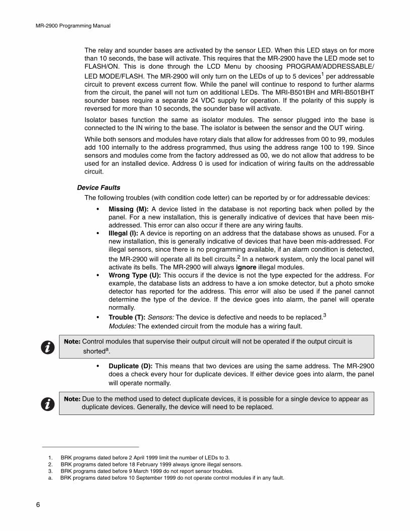
The relay and sounder bases are activated by the sensor LED. When this LED stays on for morethan 10 seconds, the base will activate. This requires that the MR-2900 have the LED mode set toFLASH/ON. This is done through the LCD Menu by choosing PROGRAM/ADDRESSABLE/
LED MODE/FLASH. The MR-2900 will only turn on the LEDs of up to 5 devices1 per addressablecircuit to prevent excess current flow. While the panel will continue to respond to further alarmsfrom the circuit, the panel will not turn on additional LEDs. The MRI-B501BH and MRI-B501BHTsounder bases require a separate 24 VDC supply for operation. If the polarity of this supply isreversed for more than 10 seconds, the sounder base will activate.
Isolator bases function the same as isolator modules. The sensor plugged into the base isconnected to the IN wiring to the base. The isolator is between the sensor and the OUT wiring.
While both sensors and modules have rotary dials that allow for addresses from 00 to 99, modulesadd 100 internally to the address programmed, thus using the address range 100 to 199. Sincesensors and modules come from the factory addressed as 00, we do not allow that address to beused for an installed device. Address 0 is used for indication of wiring faults on the addressablecircuit.
Device Faults
The following troubles (with condition code letter) can be reported by or for addressable devices:
• Missing (M): A device listed in the database is not reporting back when polled by thepanel. For a new installation, this is generally indicative of devices that have been mis-addressed. This error can also occur if there are any wiring faults.
• Illegal (I): A device is reporting on an address that the database shows as unused. For anew installation, this is generally indicative of devices that have been mis-addressed. Forillegal sensors, since there is no programming available, if an alarm condition is detected,
the MR-2900 will operate all its bell circuits.2 In a network system, only the local panel willactivate its bells. The MR-2900 will always ignore illegal modules.
• Wrong Type (U): This occurs if the device is not the type expected for the address. Forexample, the database lists an address to have a ion smoke detector, but a photo smokedetector has reported for the address. This error will also be used if the panel cannotdetermine the type of the device. If the device goes into alarm, the panel will operatenormally.
• Trouble (T): Sensors: The device is defective and needs to be replaced.3
Modules: The extended circuit from the module has a wiring fault.
• Duplicate (D): This means that two devices are using the same address. The MR-2900does a check every hour for duplicate devices. If either device goes into alarm, the panelwill operate normally.
1. BRK programs dated before 2 April 1999 limit the number of LEDs to 3.2. BRK programs dated before 18 February 1999 always ignore illegal sensors.3. BRK programs dated before 9 March 1999 do not report sensor troubles. a. BRK programs dated before 10 September 1999 do not operate control modules if in any fault.
Note: Control modules that supervise their output circuit will not be operated if the output circuit is
shorteda.
Note: Due to the method used to detect duplicate devices, it is possible for a single device to appear as duplicate devices. Generally, the device will need to be replaced.
6
MR-2900 Programming Manual
MR-2919 Class A Input Module
The MR-2919 Class A Addressable Input Module uses two input circuits, out on the odd numberedcircuit and in on the following even numbered circuit, for example: out on circuit 9 and in on circuit10. Both circuits are powered by the panel from a single source, so that there is no internalisolation between the circuits. This means that a short across one circuit will affect the other circuit.
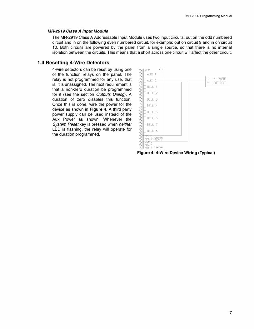
1.4 Resetting 4-Wire Detectors4-wire detectors can be reset by using oneof the function relays on the panel. Therelay is not programmed for any use, thatis, it is unassigned. The next requirement isthat a non-zero duration be programmedfor it (see the section Outputs Dialog). Aduration of zero disables this function.Once this is done, wire the power for thedevice as shown in Figure 4. A third partypower supply can be used instead of theAux Power as shown. Whenever theSystem Reset key is pressed when neitherLED is flashing, the relay will operate forthe duration programmed.
Figure 4: 4-Wire Device Wiring (Typical)
7
MR-2900 Programming Manual
2.0 Editing MHI Databases
2.1 General CommentsThe editing of a system is done through a series of input windows. Editing starts with the SystemLevel and progresses to the Panel Level, then to the Input Level, and finally to the Relate Level.The Main Menu and option speed keys are not available while editing/viewing the system. Whileediting is being done, the word OPEN is displayed in the Status Bar. This is to remind the user thatthe system database is open and that the computer should not be turned off. If the computer isturned off while the database is open, it may become corrupted.
If the current database has been previously verified and you select Edit, a requester will bedisplayed confirming your request to edit the database. If No is chosen, then the database isdisplayed in View mode. Editing the database will change the database to a non-verified state andwill change the Last Edit Date.
Prior to an editing session, the database will be automatically backed up. This back up copy willhave the same name as the original database, but will incorporate a .BAK extension. If a databasebecomes corrupted, delete it and rename its .BAK backup file to have a .DBA extension. This willrestore the database to the state prior to the last editing session.
Panel Types
There are a number of different types of panels that may be programmed. These are the onescovered:
• MR-2900 (mb2931) Fire Panel: This is an MR-2900 Control Panel using the MR-2931motherboard. This panel accepts all input circuit modules and has four Class A or eightClass B power-reversing output circuits. These output circuits can be programmed to beused as either bells or releaser type circuits. This is the standard board for the MR-2900.These panels can be used in a network configuration.
• MR-2900 (mb2921) Fire Panel: This is an MR-2900 Control Panel using the MR-2921motherboard. It is identical to the MR-2900 (mb2931) in hardware capability, but does notsupport all software features. This panel type is no longer produced.
• MR-2900 (mb2901) Fire Panel: This is an MR-2900 Control Panel using the MR-2901motherboard. This panel accepts conventional input circuit modules only and has four bellcircuits and four releaser type circuits. These circuits use different circuitry and cannothave their function changed. These panels can be used in a network configuration. Thispanel type is no longer produced.
Note: When upgrading from a version 17 (or earlier) system, a number of items that were programmed at the panel are now included in the database. See the file UPGRADE.TXT for a complete description of these changes.
Follow these instructions to obtain the required information before upgrading your firmware:
1.Connect your computer to the panel and open the Terminal window2.Select the Printer screen in the Terminal: press 14<Tab>3.You should note that the title bar of the Terminal window displays the text "File logging in
progress...". If this does not appear, press the button Log On.4.In the terminal window, type the following command: 99?5.The panel's configuration settings will be listed in the Terminal window and it will also be
saved in the file: LOG_CONT.TXT, located in your program directory6.Close the Terminal window7.You may now view the contents of the file using any standard word processor or text editor
You must perform the above procedure for ALL panels in your system
8
MR-2900 Programming Manual
• MR-2100/MR-2200 Fire Panel: Can be used in a network configuration with MR-2900control panels.
• MR-2400 Fire Panel: Not discussed in this manual.• MR-2944 Annunciator: It includes the memory required to have a database loaded into it.
This allows for less information to be sent on the network. An optional 4x20 LCD can beincluded. This annunciator has two communications ports. This allows the annunciator toreside in the network loop. It uses the MR-2910 Network Board. One of the network portscan be disabled. This results in the annunciator having to be linked to a Control Panel.With one of the ports disabled, the annunciator can not be in the network loop.
• MR-2934 Annunciator: It is identical to the MR-2944 in operation. It has the networkcommunications built onto the board instead of using the MR-2910 Network Board. Thisannunciator is no longer produced.
The MR-2614 and MR-2644 Annunciators can be attached to the MR-2900 panel. They areconsidered an extension of the panel by MHI and do not change how these panels interface withother annunciators.
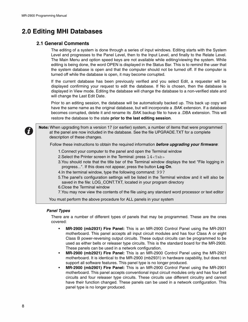
2.2 System WindowThe System Window (seeFigure 5) allows editing ofall system level options, aswell as detailing othersystem wide information.
The Title Bar of the windowwill show whether editing orviewing of the database isbeing preformed and thename of the currentdatabase.
The text in the top left cornerprovides information aboutthe database. The top linegives the date and time thedatabase was last edited.The next line states whetherthe current contents havebeen verified or not; and whether the database has been compressed or not.
The options Bell System, Subsequent Alarm, Resound, Evac and Waterflow all affect how thenotification appliance circuits (NAC), hereafter referred to as bells, react to alarm conditions. BellSystem is a drop down list for selecting how the bells and strobes will operate. This includes boththe panel outputs and any control modules programmed for bell or strobe operation. This sets thebase operation for the entire network. If coded bells are required, the bell codes are defined foreach input individually.
The following options are available:
• Alert: A First Stage alarm activates the selected bells in Alert mode. If the Signal Silenceor Second Stage Inhibit Hot Key is not pressed before the [No Acknowledge] SecondStage Inhibit timeout, the panel will progress to Second Stage. Second stage will activateall bells in Evacuation mode.
• Evac: A First Stage alarm will activate selected bells in Evacuation mode. Second Stagewill activate all bells in Evacuation mode. There is no timeout from First to Second Stage.
Figure 5: System Window
9
MR-2900 Programming Manual
• Alert/Evac: A First Stage alarm activates the selected bells in Evacuation mode and allother bells on the panel in Alert mode. If the Signal Silence or Second Stage Inhibit HotKey is not pressed before the [No Acknowledge] Second Stage Inhibit timeout, the systemwill progress to Second Stage. Second Stage will activate all bells in Evacuation mode.
• Staged: The 1st alarm will activate selected bells in Alert mode. If the Signal Silence orSecond Stage Inhibit Hot Key is not pressed before the [No Acknowledge] Second StageInhibit timeout, the selected bells are switched to Evacuation mode and the next bells, i.e.the ones with the next higher number, are activated in Alert mode. This sequence isrepeated until all bells are in Evacuation mode. When the highest numbered bell circuitswitches to Evacuation mode, all bell and strobe circuits on the panel will be turned on inEvacuation mode. For example, if the alarm activates Bells 1 and 4, after the [NoAcknowledge] Second Stage Inhibit timeout, Bells 1 and 4 are switched to Evacuationmode and Bells 2 and 5 are set to Alert mode. A 2nd alarm will activate all bells inEvacuation mode. Bells must be assigned consecutive bells circuits with no Releasersassigned in between Bells. For example: circuits 1, 2, 3, 4 can be assigned as Bells butnot circuits 1, 2, 4, 5 with circuit 3 a Releaser. Control modules cannot be programmed asbell or strobe if the Staged Bell system is used.
Subsequent Alarm controls how Alert, Evac and Alert/Evac type bell systems behave when a newalarm is received while one is still active. 1st Stage has the panel repeat the First Stage operation.2nd Stage has the panel go immediately to Second Stage operation.
Resound controls how the panels handle the automatic resounding of silenced bells when a newalarm is received. There are two modes:
• Local: Each panel will resound only its own silenced bells when a new alarm is received.This would be used when panels in a network are in different buildings, such as a campus.
• Global: All panels in a network will resound silenced bells when a new alarm condition isreceived on any panel in the network. This is used when the panels are all in the samebuilding, such as a large plant.
Evac controls whether the bell system Evacuation Mode sounds Steady (continuously) or uses aTemporal pattern as specified in ANSI S3.41 and ISO 8201 Audible Emergency Evacuation Signal.The pattern used ½s On, ½s Off, ½s On, ½s Off, ½s On, 1½s Off repeated.
Waterflow controls if bells can be silenced if they are started by a waterflow type input. If Non-Silenceable is chosen, bell circuits activated by a waterflow input cannot be silenced until thedevice has restored.
Language chooses English (default), French or Hungarian characters to be used in messages.
Alarm List Sequence controls which end of the Alarm List is shown automatically. If First is chosen,the first (oldest) item in the alarm list will be shown. If Last is chosen, the last (newest) item in thealarm list is shown. Regardless of order, alarms always take precedence in being shown. Anotherway to think of it is that First shows where the fire started while Last shows where the fire hasgotten to.
Disconnects controls which panels the Signal Disconnect, Relay Disconnect, Releaser Disconnectand Common Disconnect hot keys affect.
• Local: The Disconnect hot keys affect only the panel they are on.• Global: The Disconnect hot keys affect all the panels in the network. This means that if a
Disconnect key is pressed on any panel, all panels in the system will be affected.
The System Message is a text entry box for defining a message used to identify the system. Themessage is three lines by twenty characters long. It is printed at the top of printouts and shown onsome service terminal screens, but only seen on the LCD in the STATUS/IDENTIFICATION menu.
The System Banner is a 20 character message that is used as a banner for the Main Menu of theLCD. The default banner is “Modul-R by Secutron”.
10
MR-2900 Programming Manual
The Enforce Local LED Rules check box forces an LED on an input's panel be related. Normallyan LED anywhere in the system is all that is required.
The Allow Complex Releaser Definitions check box enables extended functionality of releasercircuits and control modules programmed for releasing. This allows for Fast (no delay) operation ofa releaser and for AND function using A and B side inputs to a releaser. See section 1.4 ReleaserProgramming for details.
The Enforce Group Association checking check box enables MHI to check to see if a groupassociation has been included in the relates of inputs. This option must be enabled when using anMRDL Dialer.
The Observe Daylight Savings Time check box enables or disables the automatic changing of theclock for Daylight Savings Time. If enabled, the system will move 1 hour ahead the second Sundayof March and fall back 1 hour the first Sunday of November (North American dates).
The Pre-alarm Buzzer, when enabled, will cause a tone to sound when a smoke detector circuit isin the auto-verify process or an addressable device is in alarm during the Retard period. The toneused is a triple beep every second.
Master ID defines which panel in a network will act as the Master panel. Only control panels maybe chosen as the Master panel. The Master panel synchronizes the date and time on all panelsand annunciators at 3:30am everyday.
Alarm List Mode sets the way the Alarm List messages are displayed on fire panels in the system.Annunciators will always receive messages as marked in the database. There are three modes ofdisplaying messages:
• Local: Each fire panel shows only Alarm List entries that are for that panel only.• Global: Each fire panel shows Alarm List entries for itself and all other panels and leave
their own annunciators.• Master: The master fire panel shows the Alarm List entries for all panels and annunciators
while all other fire panels show only their own Alarm List entries.
Common Relays controls what signals affect the common alarm, common supervisory andcommon trouble relays of each panel. The are two settings:
• Local: The common relays of a panel follow the events of events on that panel only.• follow Alarm List Mode: The common relays of a panel will react to both events of the
panel and any events listed in its Alarm List.
Non-Latch Mode controls if the panel will auto restore. The options are as follows
• None: Everything Latched
• Trouble only: Only trouble conditions will auto restore
• Supv and Trbl: Supervisory and Trouble conditions will automatically restore.
Note: The common LEDs of any panel are based upon the zone LEDs that are displayed by the panel, not based upon the inputs to the panel.
Note: Some troubles require user intervention before the panel can determine if the condition be restored
11
MR-2900 Programming Manual
The System Window has the following push buttons on the right hand side:
• Exit: Closes the System Window and, if editing, saves the database. At this time, arequester will ask if the database should be Verified. A database has to verify withouterrors before it can be downloaded.
• Panels: Displays the Panel Window. If the system has no panels defined, the Add PanelBox is displayed to obtain the first control panel for the system.
• Switches: Displays the Switches Window. This window determines which devices areattached to the switches and the timers associated to each switch. See section 2.3 for theSwitches Window.
• Groups: Displays the Groups Window. This window is used to define groups of relates.See section 2.4 for the Groups Window.
• Map: Displays and/or updates the Map Window. See section 2.8 Map Window of theModul-R Human Interface User Guide.
• Verify List: Displays the Verify List. If there is no Verify List, a requester will appear askingwhether you wish to perform a verification. See section Verify of the Modul-R HumanInterface User Guide for a full description of the Verify List and its uses.
• Settings: Defines the Verify warnings to disable and/or errors to reduce to warnings forthe current database. Not all warnings/errors can be disabled/reduced. The use of this isnot recommended, but provided for special circumstances.
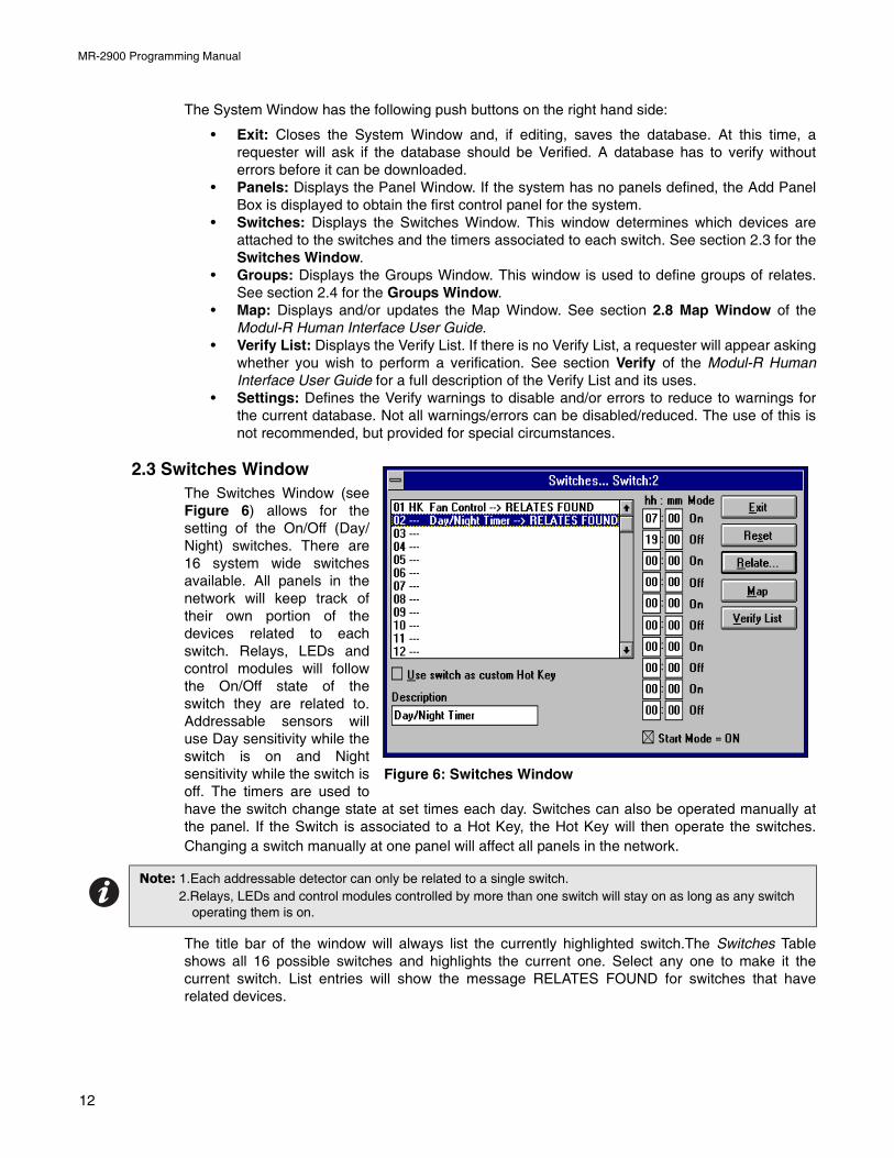
2.3 Switches WindowThe Switches Window (seeFigure 6) allows for thesetting of the On/Off (Day/Night) switches. There are16 system wide switchesavailable. All panels in thenetwork will keep track oftheir own portion of thedevices related to eachswitch. Relays, LEDs andcontrol modules will followthe On/Off state of theswitch they are related to.Addressable sensors willuse Day sensitivity while theswitch is on and Nightsensitivity while the switch isoff. The timers are used tohave the switch change state at set times each day. Switches can also be operated manually atthe panel. If the Switch is associated to a Hot Key, the Hot Key will then operate the switches.Changing a switch manually at one panel will affect all panels in the network.
The title bar of the window will always list the currently highlighted switch.The Switches Tableshows all 16 possible switches and highlights the current one. Select any one to make it thecurrent switch. List entries will show the message RELATES FOUND for switches that haverelated devices.
Note: 1.Each addressable detector can only be related to a single switch.2.Relays, LEDs and control modules controlled by more than one switch will stay on as long as any switch
operating them is on.
Figure 6: Switches Window
12
MR-2900 Programming Manual
The HH:MM (Timer) entries control the times that the switch will change state. An even number oftimes must be entered, i.e. each on must have a corresponding off. All times are entered using 24hour notation, e.g.: one minute after midnight=0:01, noon=12:00, 3 PM=15:00, 4 AM=4:00, etc. Atime of 0:00 is considered as not used. If an action at midnight is desired set the time to 0:01, oneminute after midnight; or 23:59, a minute before midnight. MHI will sort the times into ascendingorder after the Switches Window is closed.
The Start Mode - On check box determines if the first time listed should turn the switch On or Off. Ifit is not checked, the first time turns the switch off. If it is checked, the first time turns the switch on.The on and off indication beside each time entry will change to reflect what each time in the sortedlist will do.
Use switch as Custom Hot Key allows the switch to be manually controlled by the Hot Keys. A hotkey can be assigned to turn the switch on and another to turn it off. These keys will be marked asHK in the Switches Table.
Description is a 20 character message that describes the Switch usage. This is useful in that theswitch now has a description of its usage that is easier to understand when assigning Switches toHot Keys.
There are five push buttons on the right side:
• Exit: Close the Switches Window and return to the System Window. • Reset: This will remove all relates and all times for the currently highlighted switch.• Relate: Shows the Relate Window. Items marked *on* will be operated/controlled by the
switch.• Map: Displays and/or updates the Map Window. See section 2.8 for Map Window of the
Modul-R Human Interface User Guide.• Verify List: Displays the Verify List. If there is no Verify List, a requester will appear asking
whether you wish to perform a verification. See section 2.6.5 Verify of the Modul-RHuman Interface User Guide for a full description of the Verify List and its uses.
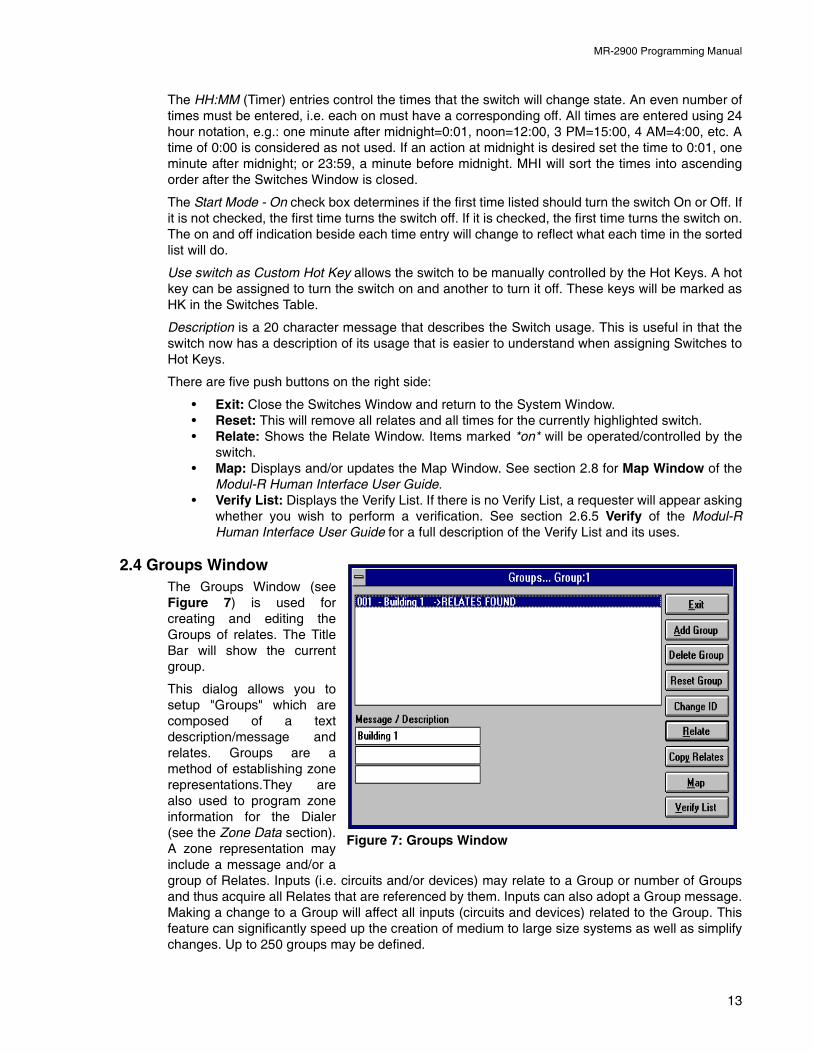
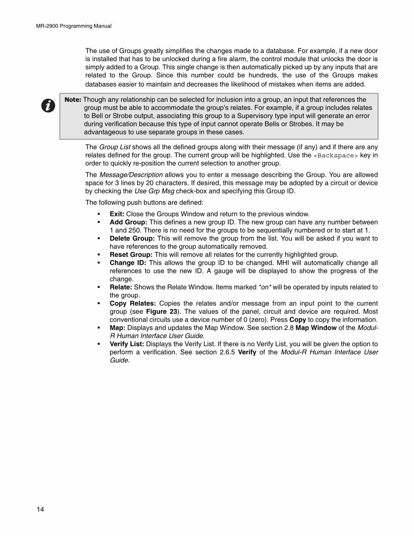
2.4 Groups WindowThe Groups Window (seeFigure 7) is used forcreating and editing theGroups of relates. The TitleBar will show the currentgroup.
This dialog allows you tosetup "Groups" which arecomposed of a textdescription/message andrelates. Groups are amethod of establishing zonerepresentations.They arealso used to program zoneinformation for the Dialer(see the Zone Data section).A zone representation mayinclude a message and/or agroup of Relates. Inputs (i.e. circuits and/or devices) may relate to a Group or number of Groupsand thus acquire all Relates that are referenced by them. Inputs can also adopt a Group message.Making a change to a Group will affect all inputs (circuits and devices) related to the Group. Thisfeature can significantly speed up the creation of medium to large size systems as well as simplifychanges. Up to 250 groups may be defined.
Figure 7: Groups Window
13
MR-2900 Programming Manual
The use of Groups greatly simplifies the changes made to a database. For example, if a new dooris installed that has to be unlocked during a fire alarm, the control module that unlocks the door issimply added to a Group. This single change is then automatically picked up by any inputs that arerelated to the Group. Since this number could be hundreds, the use of the Groups makesdatabases easier to maintain and decreases the likelihood of mistakes when items are added.
The Group List shows all the defined groups along with their message (if any) and if there are anyrelates defined for the group. The current group will be highlighted. Use the <Backspace> key inorder to quickly re-position the current selection to another group.
The Message/Description allows you to enter a message describing the Group. You are allowedspace for 3 lines by 20 characters. If desired, this message may be adopted by a circuit or deviceby checking the Use Grp Msg check-box and specifying this Group ID.
The following push buttons are defined:
• Exit: Close the Groups Window and return to the previous window.• Add Group: This defines a new group ID. The new group can have any number between
1 and 250. There is no need for the groups to be sequentially numbered or to start at 1.• Delete Group: This will remove the group from the list. You will be asked if you want to
have references to the group automatically removed.• Reset Group: This will remove all relates for the currently highlighted group.• Change ID: This allows the group ID to be changed. MHI will automatically change all
references to use the new ID. A gauge will be displayed to show the progress of thechange.
• Relate: Shows the Relate Window. Items marked *on* will be operated by inputs related tothe group.
• Copy Relates: Copies the relates and/or message from an input point to the currentgroup (see Figure 23). The values of the panel, circuit and device are required. Mostconventional circuits use a device number of 0 (zero). Press Copy to copy the information.
• Map: Displays and updates the Map Window. See section 2.8 Map Window of the Modul-R Human Interface User Guide.
• Verify List: Displays the Verify List. If there is no Verify List, you will be given the option toperform a verification. See section 2.6.5 Verify of the Modul-R Human Interface UserGuide.
Note: Though any relationship can be selected for inclusion into a group, an input that references the group must be able to accommodate the group’s relates. For example, if a group includes relates to Bell or Strobe output, associating this group to a Supervisory type input will generate an error during verification because this type of input cannot operate Bells or Strobes. It may be advantageous to use separate groups in these cases.
14
MR-2900 Programming Manual
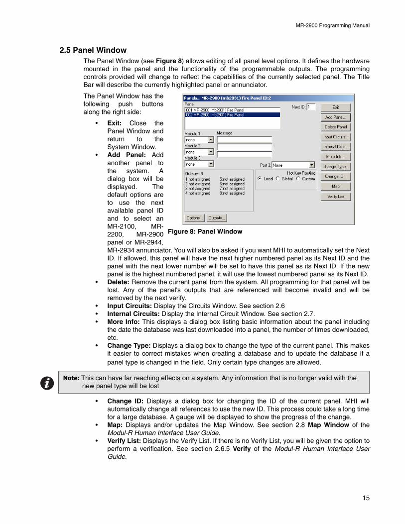
2.5 Panel WindowThe Panel Window (see Figure 8) allows editing of all panel level options. It defines the hardwaremounted in the panel and the functionality of the programmable outputs. The programmingcontrols provided will change to reflect the capabilities of the currently selected panel. The TitleBar will describe the currently highlighted panel or annunciator.
The Panel Window has thefollowing push buttonsalong the right side:
• Exit: Close thePanel Window andreturn to theSystem Window.
• Add Panel: Addanother panel tothe system. Adialog box will bedisplayed. Thedefault options areto use the nextavailable panel IDand to select anMR-2100, MR-2200, MR-2900panel or MR-2944,MR-2934 annunciator. You will also be asked if you want MHI to automatically set the NextID. If allowed, this panel will have the next higher numbered panel as its Next ID and thepanel with the next lower number will be set to have this panel as its Next ID. If the newpanel is the highest numbered panel, it will use the lowest numbered panel as its Next ID.
• Delete: Remove the current panel from the system. All programming for that panel will belost. Any of the panel's outputs that are referenced will become invalid and will beremoved by the next verify.
• Input Circuits: Display the Circuits Window. See section 2.6• Internal Circuits: Display the Internal Circuit Window. See section 2.7.• More Info: This displays a dialog box listing basic information about the panel including
the date the database was last downloaded into a panel, the number of times downloaded,etc.
• Change Type: Displays a dialog box to change the type of the current panel. This makesit easier to correct mistakes when creating a database and to update the database if apanel type is changed in the field. Only certain type changes are allowed.
• Change ID: Displays a dialog box for changing the ID of the current panel. MHI willautomatically change all references to use the new ID. This process could take a long timefor a large database. A gauge will be displayed to show the progress of the change.
• Map: Displays and/or updates the Map Window. See section 2.8 Map Window of theModul-R Human Interface User Guide.
• Verify List: Displays the Verify List. If there is no Verify List, you will be given the option toperform a verification. See section 2.6.5 Verify of the Modul-R Human Interface UserGuide.
Note: This can have far reaching effects on a system. Any information that is no longer valid with the new panel type will be lost
Figure 8: Panel Window
15

MR-2900 Programming Manual
The Panel List is located in the top left corner of the window. It lists all the panels, both Control andAnnunciator, that are defined in the system. The highlighted entry in the List is the one that iscurrently being edited. Its description is also shown in the title bar of the Panel Window. If adifferent panel is selected, all the controls in the window will change to reflect this. Use the<Backspace> key in order to quickly re-position the current selection to another panel.
The Message is located below the Panel List. This is a 3 line by 20 character message that isassociated with the Panel. This message will be displayed in Alarm Lists with signals that aregenerated by this panel. It will also be included in any print-outs generated by the Master Panel ofthe system. This message should include enough information that it will identify the panel and itslocation to fire or service personnel.
The Outputs area lists the function of the outputs of the panel. Use the Outputs Button to show theOutputs Dialog (see the Outputs Dialog section) which allows for the programming of the Outputsand the relays.
The Options button displays the Options Dialog (see the Options Dialog section). This allows forthe programming of the various panel options, such as Hot Keys, bell timers, etc.
The Next ID is located to the left of the push buttons at the top of the Panel Window. It is notdisplayed for single panel systems. It is used to define the ID of the next panel in the network loop.Specify the panel ID of the panel to be connected to the COM 1 terminals of the current panel. SeeLinks for notes on programming systems that contain single-port MR-2934 or MR-2924Annunciators.
Links is used to enter the IDs of single port annunciators that are connected to COM 1 of theMR-2900 panel. These annunciators do not reside in the network loop, but are branches off of it.
Port 3 sets the purpose of the Port 3 general communications port. If the operating programloaded does not support the selected setting, a wrong port 3 program trouble will be generated bythe panel. The options are:
• none: Port 3 is not used.• Digital Protocol 1: Sets Port 3 to use the old protocol to the SE 2000.• Digital Protocol 2: Sets Port 3 to use the new protocol to the SE 2000.• PC Connect: Sets Port 3 to use the GRID program interface.• Voice Evac. System: Sets Port 3 to communicate with the MV-2700 voice evacuation
panel.• Annunciator Connect: Sets Port 3 to communicate with the Dialer, MR-2614 or MR-2644
annunciators, or city tie module.
Local Ann. LED Cnt will be shown if any MR-2614 annunciators are chosen in the IDs Superviseddialog.
16
MR-2900 Programming Manual
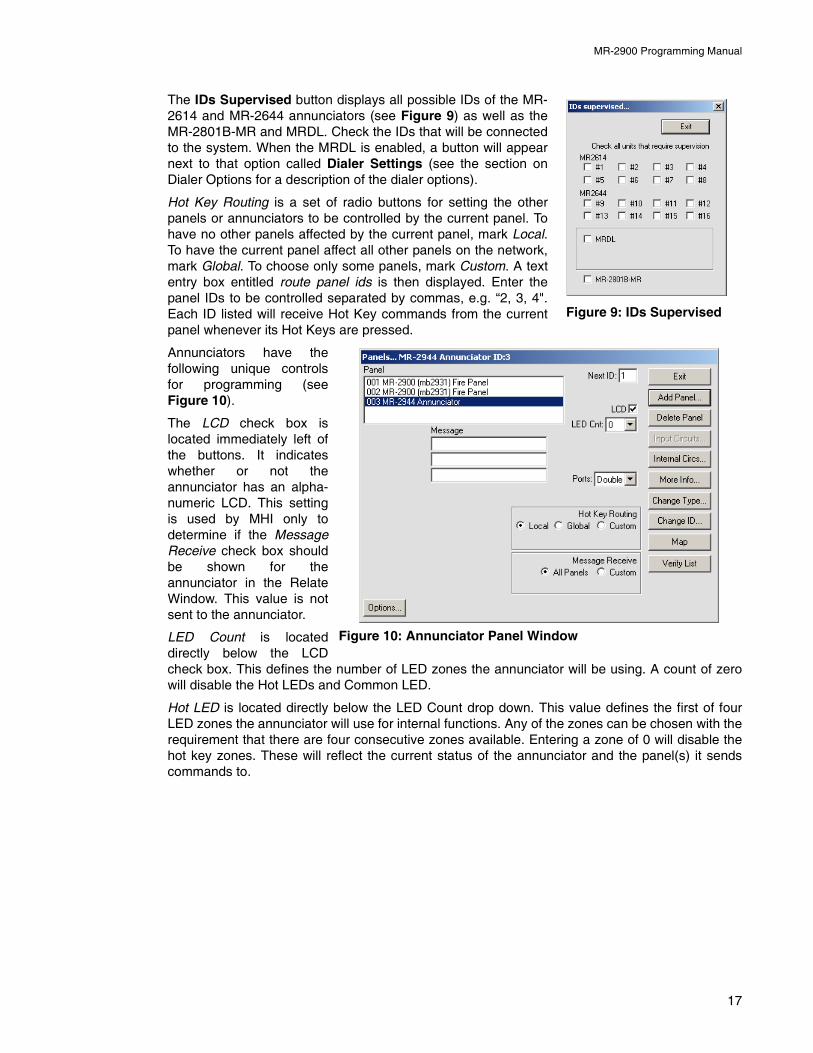
The IDs Supervised button displays all possible IDs of the MR-2614 and MR-2644 annunciators (see Figure 9) as well as theMR-2801B-MR and MRDL. Check the IDs that will be connectedto the system. When the MRDL is enabled, a button will appearnext to that option called Dialer Settings (see the section onDialer Options for a description of the dialer options).
Hot Key Routing is a set of radio buttons for setting the otherpanels or annunciators to be controlled by the current panel. Tohave no other panels affected by the current panel, mark Local.To have the current panel affect all other panels on the network,mark Global. To choose only some panels, mark Custom. A textentry box entitled route panel ids is then displayed. Enter thepanel IDs to be controlled separated by commas, e.g. “2, 3, 4".Each ID listed will receive Hot Key commands from the currentpanel whenever its Hot Keys are pressed.
Annunciators have thefollowing unique controlsfor programming (seeFigure 10).
The LCD check box islocated immediately left ofthe buttons. It indicateswhether or not theannunciator has an alpha-numeric LCD. This settingis used by MHI only todetermine if the MessageReceive check box shouldbe shown for theannunciator in the RelateWindow. This value is notsent to the annunciator.
LED Count is locateddirectly below the LCDcheck box. This defines the number of LED zones the annunciator will be using. A count of zerowill disable the Hot LEDs and Common LED.
Hot LED is located directly below the LED Count drop down. This value defines the first of fourLED zones the annunciator will use for internal functions. Any of the zones can be chosen with therequirement that there are four consecutive zones available. Entering a zone of 0 will disable thehot key zones. These will reflect the current status of the annunciator and the panel(s) it sendscommands to.
Figure 9: IDs Supervised
Figure 10: Annunciator Panel Window
17
MR-2900 Programming Manual
The LEDs have the following meaning when flashing:
Message Receive is a group of a radio buttons for setting which panels this annunciator willdisplay messages for. If all panels are chosen, every message in the system is displayed. Ifcustom is selected, then all messages from the listed panels will be displayed.
Common LED is located directly below the Hot LED setting. This is the LED zone the annunciatorwill use for common alarm, supervisory and trouble indication. It is a summation of the zone LEDsof the annunciator. Any LED zone may be used. The zone chosen will not be available for generalannunciation. Entering a zone of 0 will disable the common zone.
Ports is located below the Common LED setting. It is not displayed for MR-2914 Annunciators.This option enables (double) or disables (single) the COM 1 network port. If both ports areenabled, the Next ID text box will become available (see above for a description of Next ID).
In all MR-2900 panels
Internal Circuit 98 (common ground) must relate to LED #24 on the panel as a ground faultindicator and a label must be implmented. The MR-2614 LED Annunciator does not haveaground fault indicator. Internal circuit 98 of panel associated with this annunciator mustbe setup to map ground to LED #32 and a label must be used to indicate ground. Seesection 2.7 Internal Circuits.
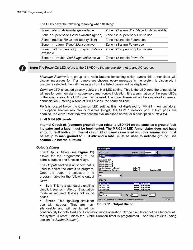
Outputs Dialog
The Outputs Dialog (see Figure 11)allows for the programming of thepanel’s outputs and function relays.
The Outputs section is a list box that isused to select the output to program.Once the output is selected, it isprogrammable for the following outputtypes:
• Bell: This is a standard signallingcircuit. It sounds in Alert or Evacuationmode as required. It does not soundcodes.• Strobe: This signalling circuit foruse with strobes. They are non-silenceable and will be turned oncontinuously for both Alert and Evacuation mode operation. Strobe circuits cannot be silenced untilthe system is reset (unless the Strobe Duration timer is programmed – see the Options Dialogsection for Strobe Duration).
Zone n alarm: Acknowledge available Zone n+2 alarm: 2nd Stage Inhibit available
Zone n supervisory: Reset available (green) Zone n+2 supervisory Future use
Zone n trouble: Reset available (yellow) Zone n+2 trouble Future use
Zone n+1 alarm: Signal Silence active Zone n+3 alarm Future use
Zone n+1 supervisory: Signal Silenceavailable
Zone n+3 supervisory Future use
Zone n+1 trouble: 2nd Stage Inhibit active Zone n+3 trouble Power On
Note: The Power On LED refers to the 24 VDC to the annunciator, not to any AC source.
Figure 11: Output Dialog
18
MR-2900 Programming Manual
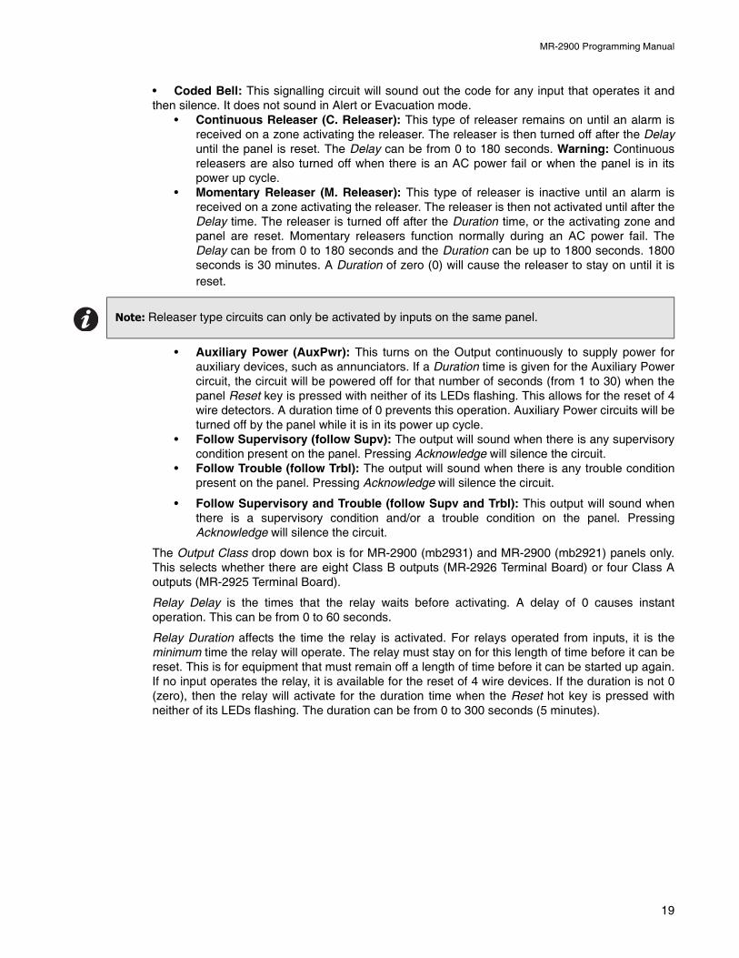
• Coded Bell: This signalling circuit will sound out the code for any input that operates it andthen silence. It does not sound in Alert or Evacuation mode.
• Continuous Releaser (C. Releaser): This type of releaser remains on until an alarm isreceived on a zone activating the releaser. The releaser is then turned off after the Delayuntil the panel is reset. The Delay can be from 0 to 180 seconds. Warning: Continuousreleasers are also turned off when there is an AC power fail or when the panel is in itspower up cycle.
• Momentary Releaser (M. Releaser): This type of releaser is inactive until an alarm isreceived on a zone activating the releaser. The releaser is then not activated until after theDelay time. The releaser is turned off after the Duration time, or the activating zone andpanel are reset. Momentary releasers function normally during an AC power fail. TheDelay can be from 0 to 180 seconds and the Duration can be up to 1800 seconds. 1800seconds is 30 minutes. A Duration of zero (0) will cause the releaser to stay on until it isreset.
• Auxiliary Power (AuxPwr): This turns on the Output continuously to supply power forauxiliary devices, such as annunciators. If a Duration time is given for the Auxiliary Powercircuit, the circuit will be powered off for that number of seconds (from 1 to 30) when thepanel Reset key is pressed with neither of its LEDs flashing. This allows for the reset of 4wire detectors. A duration time of 0 prevents this operation. Auxiliary Power circuits will beturned off by the panel while it is in its power up cycle.
• Follow Supervisory (follow Supv): The output will sound when there is any supervisorycondition present on the panel. Pressing Acknowledge will silence the circuit.
• Follow Trouble (follow Trbl): The output will sound when there is any trouble conditionpresent on the panel. Pressing Acknowledge will silence the circuit.
• Follow Supervisory and Trouble (follow Supv and Trbl): This output will sound whenthere is a supervisory condition and/or a trouble condition on the panel. PressingAcknowledge will silence the circuit.
The Output Class drop down box is for MR-2900 (mb2931) and MR-2900 (mb2921) panels only.This selects whether there are eight Class B outputs (MR-2926 Terminal Board) or four Class Aoutputs (MR-2925 Terminal Board).
Relay Delay is the times that the relay waits before activating. A delay of 0 causes instantoperation. This can be from 0 to 60 seconds.
Relay Duration affects the time the relay is activated. For relays operated from inputs, it is theminimum time the relay will operate. The relay must stay on for this length of time before it can bereset. This is for equipment that must remain off a length of time before it can be started up again.If no input operates the relay, it is available for the reset of 4 wire devices. If the duration is not 0(zero), then the relay will activate for the duration time when the Reset hot key is pressed withneither of its LEDs flashing. The duration can be from 0 to 300 seconds (5 minutes).
Note: Releaser type circuits can only be activated by inputs on the same panel.
19
MR-2900 Programming Manual
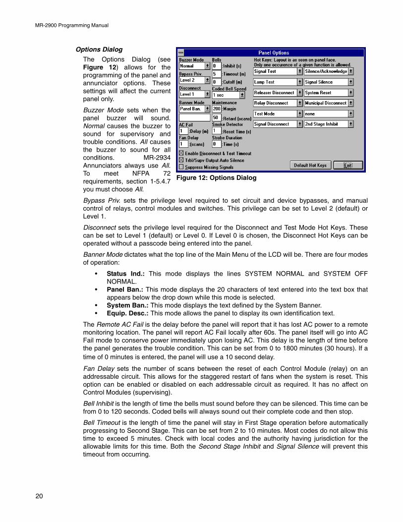
Options Dialog
The Options Dialog (seeFigure 12) allows for theprogramming of the panel andannunciator options. Thesesettings will affect the currentpanel only.
Buzzer Mode sets when thepanel buzzer will sound.Normal causes the buzzer tosound for supervisory andtrouble conditions. All causesthe buzzer to sound for allconditions. MR-2934Annunciators always use All.To meet NFPA 72requirements, section 1-5.4.7you must choose All.
Bypass Priv. sets the privilege level required to set circuit and device bypasses, and manualcontrol of relays, control modules and switches. This privilege can be set to Level 2 (default) orLevel 1.
Disconnect sets the privilege level required for the Disconnect and Test Mode Hot Keys. Thesecan be set to Level 1 (default) or Level 0. If Level 0 is chosen, the Disconnect Hot Keys can beoperated without a passcode being entered into the panel.
Banner Mode dictates what the top line of the Main Menu of the LCD will be. There are four modesof operation:
• Status Ind.: This mode displays the lines SYSTEM NORMAL and SYSTEM OFFNORMAL.
• Panel Ban.: This mode displays the 20 characters of text entered into the text box thatappears below the drop down while this mode is selected.
• System Ban.: This mode displays the text defined by the System Banner.• Equip. Desc.: This mode allows the panel to display its own identification text.
The Remote AC Fail is the delay before the panel will report that it has lost AC power to a remotemonitoring location. The panel will report AC Fail locally after 60s. The panel itself will go into ACFail mode to conserve power immediately upon losing AC. This delay is the length of time beforethe panel generates the trouble condition. This can be set from 0 to 1800 minutes (30 hours). If atime of 0 minutes is entered, the panel will use a 10 second delay.
Fan Delay sets the number of scans between the reset of each Control Module (relay) on anaddressable circuit. This allows for the staggered restart of fans when the system is reset. Thisoption can be enabled or disabled on each addressable circuit as required. It has no affect onControl Modules (supervising).
Bell Inhibit is the length of time the bells must sound before they can be silenced. This time can befrom 0 to 120 seconds. Coded bells will always sound out their complete code and then stop.
Bell Timeout is the length of time the panel will stay in First Stage operation before automaticallyprogressing to Second Stage. This can be set from 2 to 10 minutes. Most codes do not allow thistime to exceed 5 minutes. Check with local codes and the authority having jurisdiction for theallowable limits for this time. Both the Second Stage Inhibit and Signal Silence will prevent thistimeout from occurring.
Figure 12: Options Dialog
20
MR-2900 Programming Manual
Bell Cutoff is the length of time the bells will sound before they are automatically silenced by thepanel. A time of 0 disables this feature. The cutoff can be set from 5 to 30 minutes. If the cutoff isused, it must be longer than the Bell Timeout.
Coded Bell Speed sets the time interval between the bits of the codes. This speed can be 1, ¾, ½or ¼ second. The time between digits is three times this speed. The time between rounds is seventimes this speed.
Maintenance Margin sets the gap between the maintenance threshold and the alarm threshold foraddressable sensors. If the sensor stays between these two values for the Maintenance Retardtime, the panel will report a Maintenance Alert trouble for the sensor. The margin can be set from 0to 500, with 0 giving no warning and 500 giving the earliest warning.
Maintenance Retard is the number of consecutive scans the addressable sensor has to staybetween the maintenance and alarm thresholds to generate the Maintenance Alert trouble. Thisretard can be from 5 to 50 scans. Scan time can vary from 2.5 to 5 seconds with usual values from3.5 to 4 seconds.
Smoke Detector Reset Time sets the time the MR-2900 will power off conventional 2-wire smokedetectors to reset them. This time can be from 1 to 20 seconds. Current smoke detectors onlyneed the default value of 1 second. Older smoke detectors may need a longer time to reset.
Strobe Duration Time sets the time that strobe circuits will operate when activated when operatedalong with coded bells. The timer starts when the coded bells start. At the end of the timer, thestrobes are silenced. A time of 0 (zero) disables the automatic silence. This value can be from 10to 510 seconds.
Enable Disconnect & Test Timeout enables or disables disconnect timeouts. If the timeouts aredisabled, Relay Disconnect, Releaser Disconnect, Signal Disconnect, Common Disconnect andTest Mode must all be manually ended. If enabled, these functions will be automatically endedafter four hours.
Trbl/Supv Output Auto Silence enables or disables the automatic silencing of the Follow Troubleand Follow Supervisory outputs during a fire condition. If enabled, the Follow Trouble and FollowSupervisory outputs will automatically sound again once the fire bells and strobes have beensilenced.
Suppress Missing Signals allows for the suppression of device missing signals for a loop that hasa short or ground fault condition. If enabled, the panel will only report the short or ground faultcondition, but not the missing device messages.
Note: This feature requires that the BRK program be dated 9 September 1999 or later (version 17.20 or later).
21
MR-2900 Programming Manual
ll.
f
,
t
il
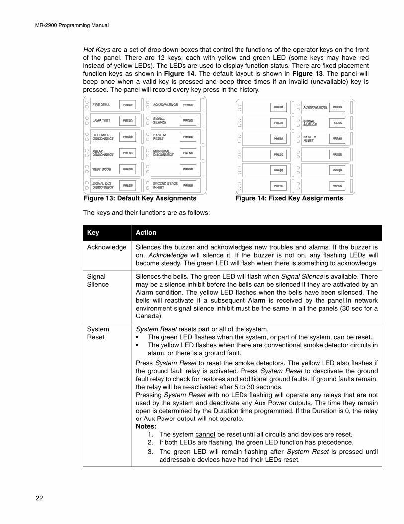
Hot Keys are a set of drop down boxes that control the functions of the operator keys on the frontof the panel. There are 12 keys, each with yellow and green LED (some keys may have redinstead of yellow LEDs). The LEDs are used to display function status. There are fixed placementfunction keys as shown in Figure 14. The default layout is shown in Figure 13. The panel willbeep once when a valid key is pressed and beep three times if an invalid (unavailable) key ispressed. The panel will record every key press in the history.
The keys and their functions are as follows:
Key Action
Acknowledge Silences the buzzer and acknowledges new troubles and alarms. If the buzzer ison, Acknowledge will silence it. If the buzzer is not on, any flashing LEDs wibecome steady. The green LED will flash when there is something to acknowledge
SignalSilence
Silences the bells. The green LED will flash when Signal Silence is available. Theremay be a silence inhibit before the bells can be silenced if they are activated by anAlarm condition. The yellow LED flashes when the bells have been silenced. Thebells will reactivate if a subsequent Alarm is received by the panel.In networkenvironment signal silence inhibit must be the same in all the panels (30 sec for aCanada).
SystemReset
System Reset resets part or all of the system.• The green LED flashes when the system, or part of the system, can be reset. • The yellow LED flashes when there are conventional smoke detector circuits in
alarm, or there is a ground fault.
Press System Reset to reset the smoke detectors. The yellow LED also flashes ithe ground fault relay is activated. Press System Reset to deactivate the groundfault relay to check for restores and additional ground faults. If ground faults remainthe relay will be re-activated after 5 to 30 seconds.Pressing System Reset with no LEDs flashing will operate any relays that are noused by the system and deactivate any Aux Power outputs. The time they remainopen is determined by the Duration time programmed. If the Duration is 0, the relayor Aux Power output will not operate.Notes:
1. The system cannot be reset until all circuits and devices are reset.2. If both LEDs are flashing, the green LED function has precedence.3. The green LED will remain flashing after System Reset is pressed unt
addressable devices have had their LEDs reset.
Figure 13: Default Key Assignments Figure 14: Fixed Key Assignments
22
MR-2900 Programming Manual
ll
ll
.f
t
llt
l
r
ll
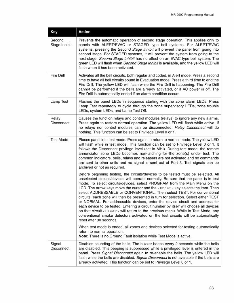
SecondStage Inhibit
Prevents the automatic operation of second stage operation. This applies only topanels with ALERT/EVAC or STAGED type bell systems. For ALERT/EVACsystems, pressing the Second Stage Inhibit will prevent the panel from going intosecond stage. For STAGED systems, it will prevent the system from going to thenext stage. Second Stage Inhibit has no effect on an EVAC type bell system. Thegreen LED will flash when Second Stage Inhibit is available, and the yellow LED wiflash when it has been activated.
Fire Drill Activates all the bell circuits, both regular and coded, in Alert mode. Press a secondtime to have all bell circuits sound in Evacuation mode. Press a third time to end theFire Drill. The yellow LED will flash while the Fire Drill is happening. The Fire Dricannot be performed if the bells are already activated, or if AC power is off. TheFire Drill is automatically ended if an alarm condition occurs.
Lamp Test Flashes the panel LEDs in sequence starting with the zone alarm LEDs. PressLamp Test repeatedly to cycle through the zone supervisory LEDs, zone troubleLEDs, system LEDs, and Lamp Test Off.
RelayDisconnect
Causes the function relays and control modules (relays) to ignore any new alarmsPress again to restore normal operation. The yellow LED will flash while active. Ino relays nor control modules can be disconnected, Relay Disconnect will donothing. This function can be set to Privilege Level 0 or 1.
Test Mode Places panel into test mode. Press again to return to normal mode. The yellow LEDwill flash while in test mode. This function can be set to Privilege Level 0 or 1. Ifollows the Disconnect privilege level (set in MHI). During test mode, the remoteannunciator zone LEDs becomes non-latching for the zone(s) under test. Thecommon indicators, bells, relays and releasers are not activated and no commandsare sent to other units and no signal is sent out of Port 3. Test signals can bearchived or not as required.
Before beginning testing, the circuits/devices to be tested must be selected. Aunselected circuits/devices will operate normally. Be sure that the panel is in tesmode. To select circuits/devices, select PROGRAM from the Main Menu on theLCD. The arrow keys move the cursor and the <Enter> key selects the item. Thenselect ADDRESSABLE or CONVENTIONAL. Then select TEST. For conventionacircuits, each zone will then be presented in turn for selection. Select either TESTor NORMAL. For addressable devices, enter the device circuit and address foeach device to be tested. Entering a circuit number by itself will choose all deviceson that circuit.<Clear> will return to the previous menu. While in Test Mode, anyconventional smoke detectors activated on the test circuits will be automaticallyreset after 30 seconds.
When test mode is ended, all zones and devices selected for testing automaticallyreturn to normal operation.Note: There is no Ground Fault isolation while Test Mode is active.
SignalDisconnect
Disables sounding of the bells. The buzzer beeps every 2 seconds while the bellsare disabled. This beeping is suppressed while a privileged level is entered in thepanel. Press Signal Disconnect again to re-enable the bells. The yellow LED wiflash while the bells are disabled. Signal Disconnect is not available if the bells arealready activated. This function can be set to Privilege Level 0 or 1.
Key Action
23
MR-2900 Programming Manual
l
l
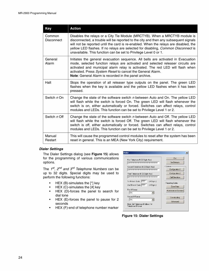
Dialer Settings
The Dialer Settings dialog (see Figure 15) allowsfor the programming of various communicationsoptions.
The 1st, 2nd and 3rd Telephone Numbers can beup to 32 digits. Special digits may be used toperform the following functions:
• HEX (B)-simulates the [*] key• HEX (C)-simulates the [#] key• HEX (D)-forces the panel to search for
dial tone• HEX (E)-forces the panel to pause for 2
seconds• HEX (F)-end of telephone number marker
CommonDisconnect
Disables the relays or a City Tie Module (MRCTYB). When a MRCTYB module isdisconnected, a trouble will be reported to the city and then any subsequent signalswill not be reported until the card is re-enabled. When the relays are disabled, theyellow LED flashes. If no relays are selected for disabling, Common Disconnect isunavailable. This function can be set to Privilege Level 0 or 1.
GeneralAlarm
Initiates the general evacuation sequence. All bells are activated in Evacuationmode, selected function relays are activated and selected releaser circuits areactivated and municipal alarm relay is activated. The red LED will flash whenactivated. Press System Reset to cancel the General Alarm.Note: General Alarm is recorded in the panel archive.
Halt Stops the operation of all releaser type outputs on the panel. The green LEDflashes when the key is available and the yellow LED flashes when it has beenpressed.
Switch n On Change the state of the software switch n between Auto and On. The yellow LEDwill flash while the switch is forced On. The green LED will flash whenever theswitch is on, either automatically or forced. Switches can affect relays, contromodules and LEDs. This function can be set to Privilege Level 1 or 2.
Switch n Off Change the state of the software switch n between Auto and Off. The yellow LEDwill flash while the switch is forced Off. The green LED will flash whenever theswitch is off, either automatically or forced. Switches can affect relays, contromodules and LEDs. This function can be set to Privilege Level 1 or 2.
ManualRestart
This will cause the programmed control modules to reset after the system has beenreset in general. This is an MEA (New York City) requirement.
Key Action
Figure 15: Dialer Settings
24
MR-2900 Programming Manual
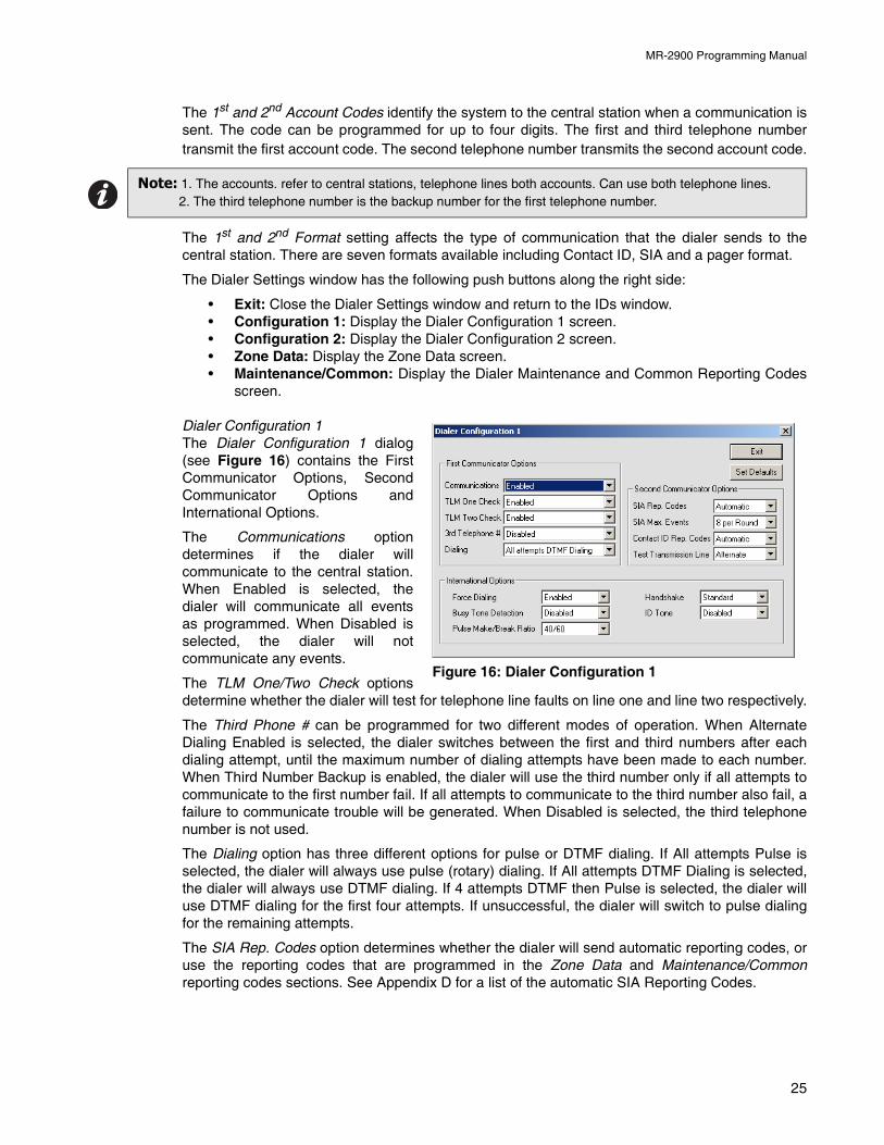
The 1st and 2nd Account Codes identify the system to the central station when a communication issent. The code can be programmed for up to four digits. The first and third telephone numbertransmit the first account code. The second telephone number transmits the second account code.
The 1st and 2nd Format setting affects the type of communication that the dialer sends to thecentral station. There are seven formats available including Contact ID, SIA and a pager format.
The Dialer Settings window has the following push buttons along the right side:
• Exit: Close the Dialer Settings window and return to the IDs window.• Configuration 1: Display the Dialer Configuration 1 screen.• Configuration 2: Display the Dialer Configuration 2 screen.• Zone Data: Display the Zone Data screen.• Maintenance/Common: Display the Dialer Maintenance and Common Reporting Codes
screen.
Dialer Configuration 1The Dialer Configuration 1 dialog(see Figure 16) contains the FirstCommunicator Options, SecondCommunicator Options andInternational Options.
The Communications optiondetermines if the dialer willcommunicate to the central station.When Enabled is selected, thedialer will communicate all eventsas programmed. When Disabled isselected, the dialer will notcommunicate any events.
The TLM One/Two Check optionsdetermine whether the dialer will test for telephone line faults on line one and line two respectively.
The Third Phone # can be programmed for two different modes of operation. When AlternateDialing Enabled is selected, the dialer switches between the first and third numbers after eachdialing attempt, until the maximum number of dialing attempts have been made to each number.When Third Number Backup is enabled, the dialer will use the third number only if all attempts tocommunicate to the first number fail. If all attempts to communicate to the third number also fail, afailure to communicate trouble will be generated. When Disabled is selected, the third telephonenumber is not used.
The Dialing option has three different options for pulse or DTMF dialing. If All attempts Pulse isselected, the dialer will always use pulse (rotary) dialing. If All attempts DTMF Dialing is selected,the dialer will always use DTMF dialing. If 4 attempts DTMF then Pulse is selected, the dialer willuse DTMF dialing for the first four attempts. If unsuccessful, the dialer will switch to pulse dialingfor the remaining attempts.
The SIA Rep. Codes option determines whether the dialer will send automatic reporting codes, oruse the reporting codes that are programmed in the Zone Data and Maintenance/Commonreporting codes sections. See Appendix D for a list of the automatic SIA Reporting Codes.
Note: 1. The accounts. refer to central stations, telephone lines both accounts. Can use both telephone lines.2. The third telephone number is the backup number for the first telephone number.
Figure 16: Dialer Configuration 1
25
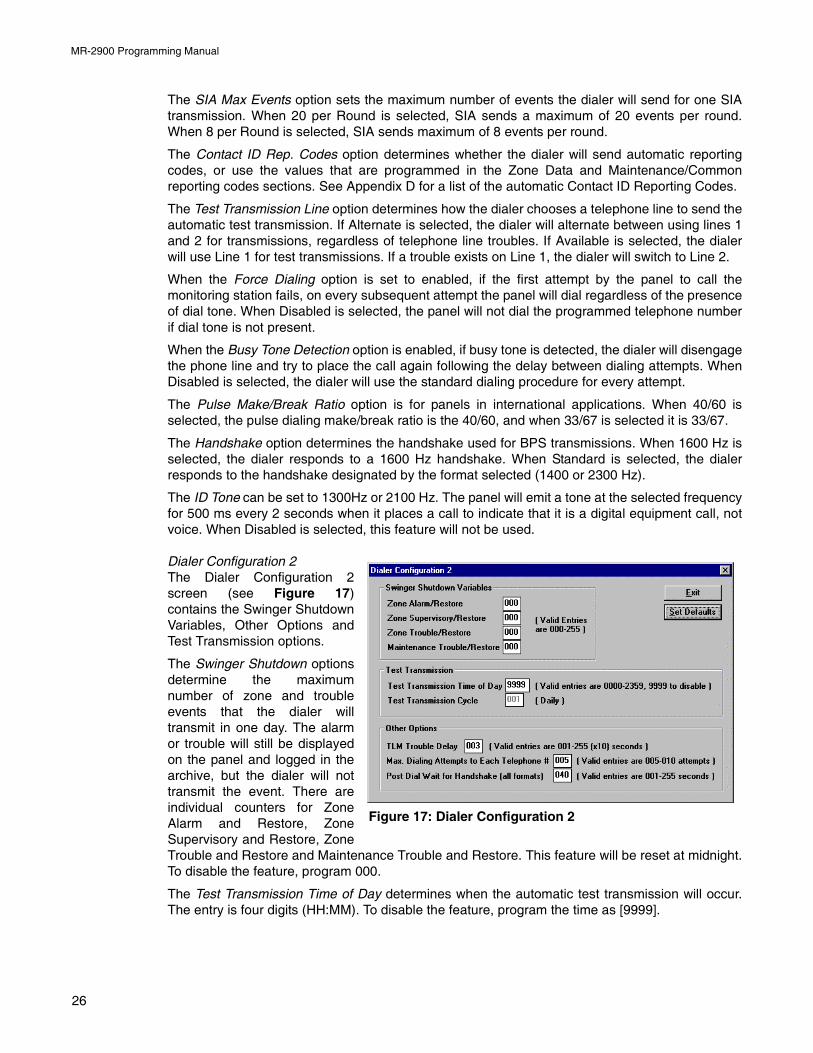
MR-2900 Programming Manual
The SIA Max Events option sets the maximum number of events the dialer will send for one SIAtransmission. When 20 per Round is selected, SIA sends a maximum of 20 events per round.When 8 per Round is selected, SIA sends maximum of 8 events per round.
The Contact ID Rep. Codes option determines whether the dialer will send automatic reportingcodes, or use the values that are programmed in the Zone Data and Maintenance/Commonreporting codes sections. See Appendix D for a list of the automatic Contact ID Reporting Codes.
The Test Transmission Line option determines how the dialer chooses a telephone line to send theautomatic test transmission. If Alternate is selected, the dialer will alternate between using lines 1and 2 for transmissions, regardless of telephone line troubles. If Available is selected, the dialerwill use Line 1 for test transmissions. If a trouble exists on Line 1, the dialer will switch to Line 2.
When the Force Dialing option is set to enabled, if the first attempt by the panel to call themonitoring station fails, on every subsequent attempt the panel will dial regardless of the presenceof dial tone. When Disabled is selected, the panel will not dial the programmed telephone numberif dial tone is not present.
When the Busy Tone Detection option is enabled, if busy tone is detected, the dialer will disengagethe phone line and try to place the call again following the delay between dialing attempts. WhenDisabled is selected, the dialer will use the standard dialing procedure for every attempt.
The Pulse Make/Break Ratio option is for panels in international applications. When 40/60 isselected, the pulse dialing make/break ratio is the 40/60, and when 33/67 is selected it is 33/67.
The Handshake option determines the handshake used for BPS transmissions. When 1600 Hz isselected, the dialer responds to a 1600 Hz handshake. When Standard is selected, the dialerresponds to the handshake designated by the format selected (1400 or 2300 Hz).
The ID Tone can be set to 1300Hz or 2100 Hz. The panel will emit a tone at the selected frequencyfor 500 ms every 2 seconds when it places a call to indicate that it is a digital equipment call, notvoice. When Disabled is selected, this feature will not be used.
Dialer Configuration 2The Dialer Configuration 2screen (see Figure 17)contains the Swinger ShutdownVariables, Other Options andTest Transmission options.
The Swinger Shutdown optionsdetermine the maximumnumber of zone and troubleevents that the dialer willtransmit in one day. The alarmor trouble will still be displayedon the panel and logged in thearchive, but the dialer will nottransmit the event. There areindividual counters for ZoneAlarm and Restore, ZoneSupervisory and Restore, ZoneTrouble and Restore and Maintenance Trouble and Restore. This feature will be reset at midnight.To disable the feature, program 000.
The Test Transmission Time of Day determines when the automatic test transmission will occur.The entry is four digits (HH:MM). To disable the feature, program the time as [9999].
Figure 17: Dialer Configuration 2
26
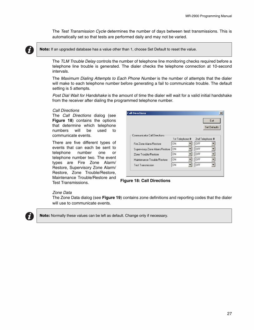
MR-2900 Programming Manual
The Test Transmission Cycle determines the number of days between test transmissions. This isautomatically set so that tests are performed daily and may not be varied.
The TLM Trouble Delay controls the number of telephone line monitoring checks required before atelephone line trouble is generated. The dialer checks the telephone connection at 10-secondintervals.
The Maximum Dialing Attempts to Each Phone Number is the number of attempts that the dialerwill make to each telephone number before generating a fail to communicate trouble. The defaultsetting is 5 attempts.
Post Dial Wait for Handshake is the amount of time the dialer will wait for a valid initial handshakefrom the receiver after dialing the programmed telephone number.
Call DirectionsThe Call Directions dialog (seeFigure 18) contains the optionsthat determine which telephonenumbers will be used tocommunicate events.
There are five different types ofevents that can each be sent totelephone number one ortelephone number two. The eventtypes are Fire Zone Alarm/Restore, Supervisory Zone Alarm/Restore, Zone Trouble/Restore,Maintenance Trouble/Restore andTest Transmissions.
Zone DataThe Zone Data dialog (see Figure 19) contains zone definitions and reporting codes that the dialerwill use to communicate events.
Note: If an upgraded database has a value other than 1, choose Set Default to reset the value.
Note: Normally these values can be left as default. Change only if necessary.
Figure 18: Call Directions
27
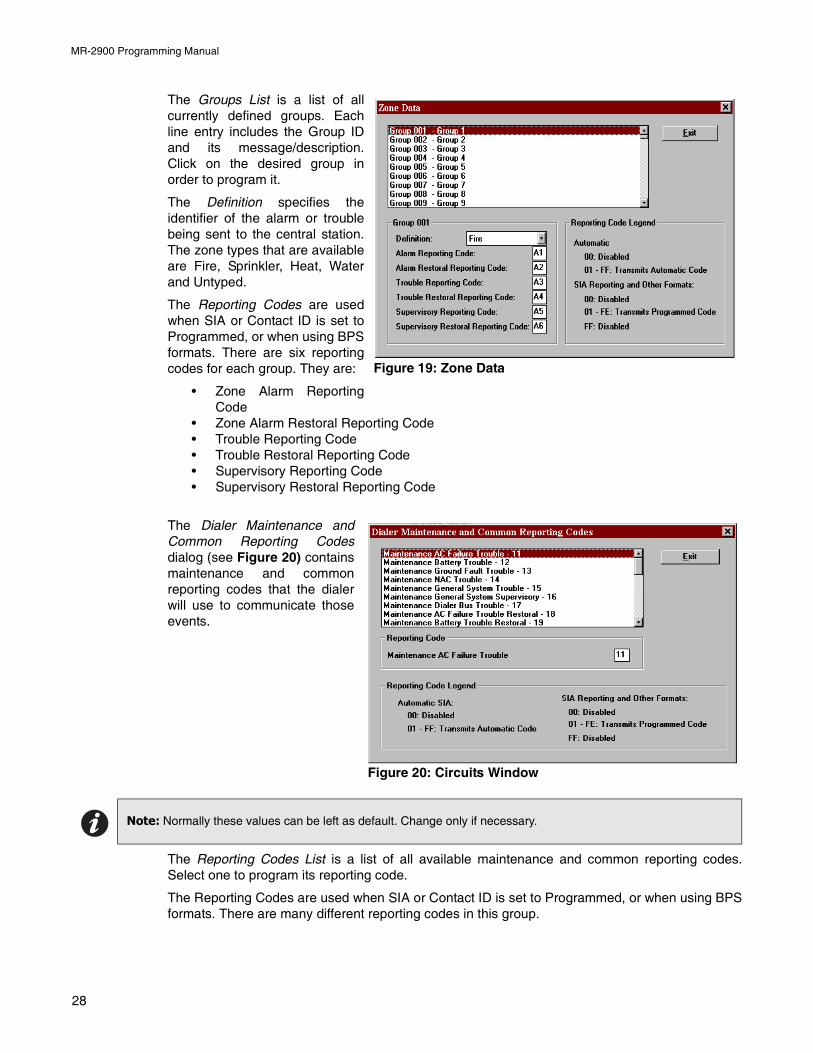
MR-2900 Programming Manual
The Groups List is a list of allcurrently defined groups. Eachline entry includes the Group IDand its message/description.Click on the desired group inorder to program it.
The Definition specifies theidentifier of the alarm or troublebeing sent to the central station.The zone types that are availableare Fire, Sprinkler, Heat, Waterand Untyped.
The Reporting Codes are usedwhen SIA or Contact ID is set toProgrammed, or when using BPSformats. There are six reportingcodes for each group. They are:
• Zone Alarm ReportingCode
• Zone Alarm Restoral Reporting Code• Trouble Reporting Code• Trouble Restoral Reporting Code• Supervisory Reporting Code• Supervisory Restoral Reporting Code
The Dialer Maintenance andCommon Reporting Codesdialog (see Figure 20) containsmaintenance and commonreporting codes that the dialerwill use to communicate thoseevents.
The Reporting Codes List is a list of all available maintenance and common reporting codes.Select one to program its reporting code.
The Reporting Codes are used when SIA or Contact ID is set to Programmed, or when using BPSformats. There are many different reporting codes in this group.
Note: Normally these values can be left as default. Change only if necessary.
Figure 19: Zone Data
Figure 20: Circuits Window
28
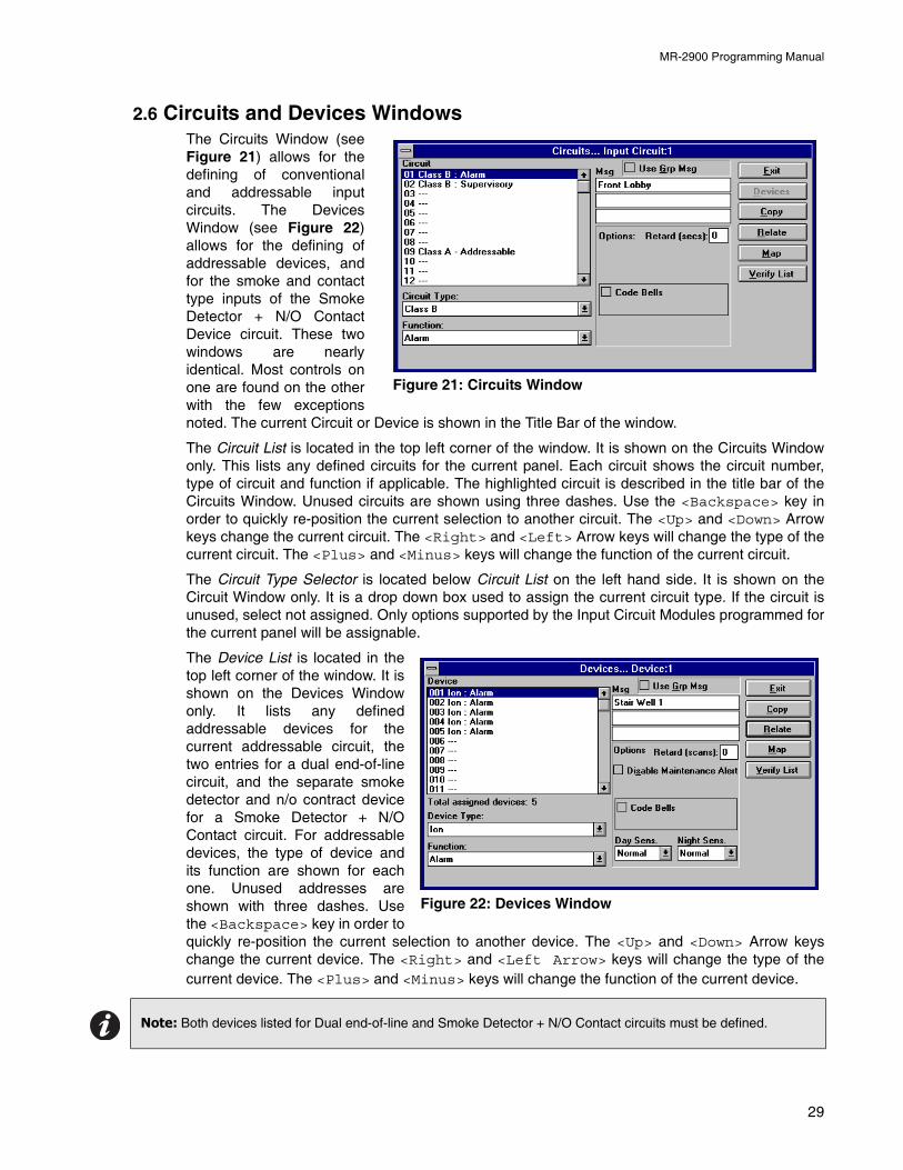
MR-2900 Programming Manual
2.6 Circuits and Devices WindowsThe Circuits Window (seeFigure 21) allows for thedefining of conventionaland addressable inputcircuits. The DevicesWindow (see Figure 22)allows for the defining ofaddressable devices, andfor the smoke and contacttype inputs of the SmokeDetector + N/O ContactDevice circuit. These twowindows are nearlyidentical. Most controls onone are found on the otherwith the few exceptionsnoted. The current Circuit or Device is shown in the Title Bar of the window.
The Circuit List is located in the top left corner of the window. It is shown on the Circuits Windowonly. This lists any defined circuits for the current panel. Each circuit shows the circuit number,type of circuit and function if applicable. The highlighted circuit is described in the title bar of theCircuits Window. Unused circuits are shown using three dashes. Use the <Backspace> key inorder to quickly re-position the current selection to another circuit. The <Up> and <Down> Arrowkeys change the current circuit. The <Right> and <Left> Arrow keys will change the type of thecurrent circuit. The <Plus> and <Minus> keys will change the function of the current circuit.
The Circuit Type Selector is located below Circuit List on the left hand side. It is shown on theCircuit Window only. It is a drop down box used to assign the current circuit type. If the circuit isunused, select not assigned. Only options supported by the Input Circuit Modules programmed forthe current panel will be assignable.
The Device List is located in thetop left corner of the window. It isshown on the Devices Windowonly. It lists any definedaddressable devices for thecurrent addressable circuit, thetwo entries for a dual end-of-linecircuit, and the separate smokedetector and n/o contract devicefor a Smoke Detector + N/OContact circuit. For addressabledevices, the type of device andits function are shown for eachone. Unused addresses areshown with three dashes. Usethe <Backspace> key in order toquickly re-position the current selection to another device. The <Up> and <Down> Arrow keyschange the current device. The <Right> and <Left Arrow> keys will change the type of thecurrent device. The <Plus> and <Minus> keys will change the function of the current device.
Note: Both devices listed for Dual end-of-line and Smoke Detector + N/O Contact circuits must be defined.
Figure 21: Circuits Window
Figure 22: Devices Window
29
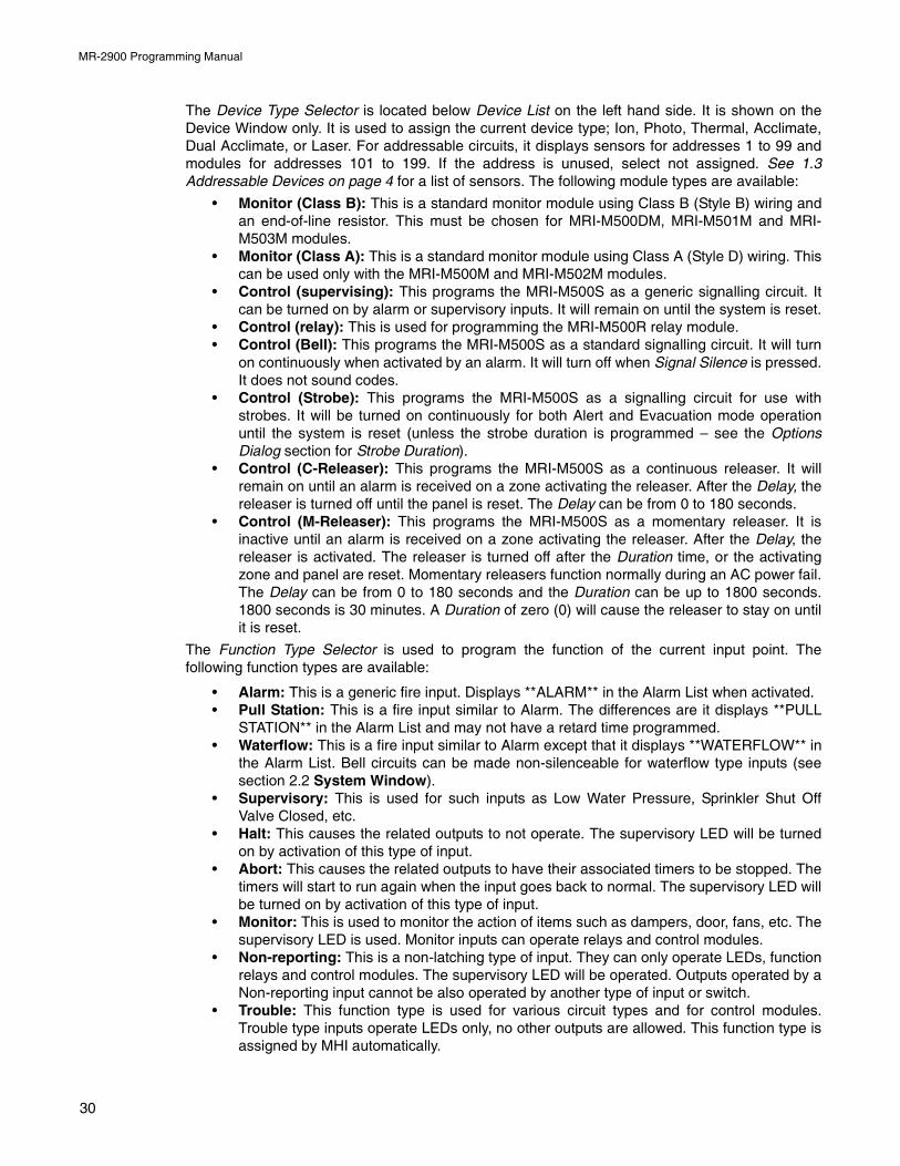
MR-2900 Programming Manual
The Device Type Selector is located below Device List on the left hand side. It is shown on theDevice Window only. It is used to assign the current device type; Ion, Photo, Thermal, Acclimate,Dual Acclimate, or Laser. For addressable circuits, it displays sensors for addresses 1 to 99 andmodules for addresses 101 to 199. If the address is unused, select not assigned. See 1.3Addressable Devices on page 4 for a list of sensors. The following module types are available:
• Monitor (Class B): This is a standard monitor module using Class B (Style B) wiring andan end-of-line resistor. This must be chosen for MRI-M500DM, MRI-M501M and MRI-M503M modules.
• Monitor (Class A): This is a standard monitor module using Class A (Style D) wiring. Thiscan be used only with the MRI-M500M and MRI-M502M modules.
• Control (supervising): This programs the MRI-M500S as a generic signalling circuit. Itcan be turned on by alarm or supervisory inputs. It will remain on until the system is reset.
• Control (relay): This is used for programming the MRI-M500R relay module.• Control (Bell): This programs the MRI-M500S as a standard signalling circuit. It will turn
on continuously when activated by an alarm. It will turn off when Signal Silence is pressed.It does not sound codes.
• Control (Strobe): This programs the MRI-M500S as a signalling circuit for use withstrobes. It will be turned on continuously for both Alert and Evacuation mode operationuntil the system is reset (unless the strobe duration is programmed – see the OptionsDialog section for Strobe Duration).
• Control (C-Releaser): This programs the MRI-M500S as a continuous releaser. It willremain on until an alarm is received on a zone activating the releaser. After the Delay, thereleaser is turned off until the panel is reset. The Delay can be from 0 to 180 seconds.
• Control (M-Releaser): This programs the MRI-M500S as a momentary releaser. It isinactive until an alarm is received on a zone activating the releaser. After the Delay, thereleaser is activated. The releaser is turned off after the Duration time, or the activatingzone and panel are reset. Momentary releasers function normally during an AC power fail.The Delay can be from 0 to 180 seconds and the Duration can be up to 1800 seconds.1800 seconds is 30 minutes. A Duration of zero (0) will cause the releaser to stay on untilit is reset.
The Function Type Selector is used to program the function of the current input point. Thefollowing function types are available:
• Alarm: This is a generic fire input. Displays **ALARM** in the Alarm List when activated.• Pull Station: This is a fire input similar to Alarm. The differences are it displays **PULL
STATION** in the Alarm List and may not have a retard time programmed.• Waterflow: This is a fire input similar to Alarm except that it displays **WATERFLOW** in
the Alarm List. Bell circuits can be made non-silenceable for waterflow type inputs (seesection 2.2 System Window).
• Supervisory: This is used for such inputs as Low Water Pressure, Sprinkler Shut OffValve Closed, etc.
• Halt: This causes the related outputs to not operate. The supervisory LED will be turnedon by activation of this type of input.
• Abort: This causes the related outputs to have their associated timers to be stopped. Thetimers will start to run again when the input goes back to normal. The supervisory LED willbe turned on by activation of this type of input.
• Monitor: This is used to monitor the action of items such as dampers, door, fans, etc. Thesupervisory LED is used. Monitor inputs can operate relays and control modules.
• Non-reporting: This is a non-latching type of input. They can only operate LEDs, functionrelays and control modules. The supervisory LED will be operated. Outputs operated by aNon-reporting input cannot be also operated by another type of input or switch.
• Trouble: This function type is used for various circuit types and for control modules.Trouble type inputs operate LEDs only, no other outputs are allowed. This function type isassigned by MHI automatically.
30
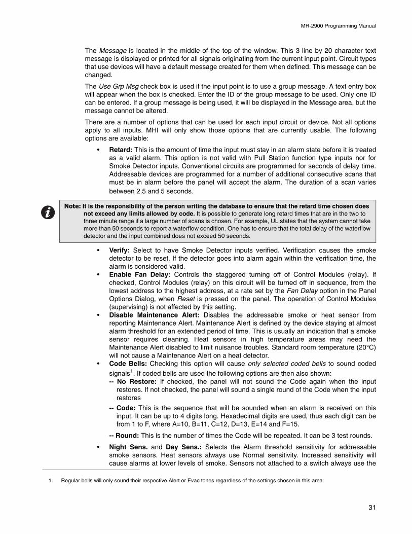
MR-2900 Programming Manual
The Message is located in the middle of the top of the window. This 3 line by 20 character textmessage is displayed or printed for all signals originating from the current input point. Circuit typesthat use devices will have a default message created for them when defined. This message can bechanged.
The Use Grp Msg check box is used if the input point is to use a group message. A text entry boxwill appear when the box is checked. Enter the ID of the group message to be used. Only one IDcan be entered. If a group message is being used, it will be displayed in the Message area, but themessage cannot be altered.
There are a number of options that can be used for each input circuit or device. Not all optionsapply to all inputs. MHI will only show those options that are currently usable. The followingoptions are available:
• Retard: This is the amount of time the input must stay in an alarm state before it is treatedas a valid alarm. This option is not valid with Pull Station function type inputs nor forSmoke Detector inputs. Conventional circuits are programmed for seconds of delay time.Addressable devices are programmed for a number of additional consecutive scans thatmust be in alarm before the panel will accept the alarm. The duration of a scan variesbetween 2.5 and 5 seconds.
• Verify: Select to have Smoke Detector inputs verified. Verification causes the smokedetector to be reset. If the detector goes into alarm again within the verification time, thealarm is considered valid.
• Enable Fan Delay: Controls the staggered turning off of Control Modules (relay). Ifchecked, Control Modules (relay) on this circuit will be turned off in sequence, from thelowest address to the highest address, at a rate set by the Fan Delay option in the PanelOptions Dialog, when Reset is pressed on the panel. The operation of Control Modules(supervising) is not affected by this setting.
• Disable Maintenance Alert: Disables the addressable smoke or heat sensor fromreporting Maintenance Alert. Maintenance Alert is defined by the device staying at almostalarm threshold for an extended period of time. This is usually an indication that a smokesensor requires cleaning. Heat sensors in high temperature areas may need theMaintenance Alert disabled to limit nuisance troubles. Standard room temperature (20°C)will not cause a Maintenance Alert on a heat detector.
• Code Bells: Checking this option will cause only selected coded bells to sound coded
signals1. If coded bells are used the following options are then also shown:-- No Restore: If checked, the panel will not sound the Code again when the input
restores. If not checked, the panel will sound a single round of the Code when the inputrestores
-- Code: This is the sequence that will be sounded when an alarm is received on thisinput. It can be up to 4 digits long. Hexadecimal digits are used, thus each digit can befrom 1 to F, where A=10, B=11, C=12, D=13, E=14 and F=15.
-- Round: This is the number of times the Code will be repeated. It can be 3 test rounds.
• Night Sens. and Day Sens.: Selects the Alarm threshold sensitivity for addressablesmoke sensors. Heat sensors always use Normal sensitivity. Increased sensitivity willcause alarms at lower levels of smoke. Sensors not attached to a switch always use the
Note: It is the responsibility of the person writing the database to ensure that the retard time chosen does not exceed any limits allowed by code. It is possible to generate long retard times that are in the two to three minute range if a large number of scans is chosen. For example, UL states that the system cannot take more than 50 seconds to report a waterflow condition. One has to ensure that the total delay of the waterflow detector and the input combined does not exceed 50 seconds.
1. Regular bells will only sound their respective Alert or Evac tones regardless of the settings chosen in this area.
31
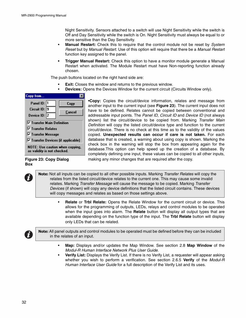
MR-2900 Programming Manual
Night Sensitivity. Sensors attached to a switch will use Night Sensitivity while the switch isOff and Day Sensitivity while the switch is On. Night Sensitivity must always be equal to ormore sensitive than the Day Sensitivity.
• Manual Restart: Check this to require that the control module not be reset by SystemReset but by Manual Restart. Use of this option will require that there be a Manual Restartfunction key assigned to the panel.
• Trigger Manual Restart: Check this option to have a monitor module generate a ManualRestart when activated. The Module Restart must have Non-reporting function alreadychosen.
The push buttons located on the right hand side are:
• Exit: Closes the window and returns to the previous window.• Devices: Opens the Devices Window for the current circuit (Circuits Window only).
•Copy: Copies the circuit/device information, relates and message fromanother input to the current input (see Figure 23). The current input does nothave to be defined. Relates cannot be copied between conventional andaddressable input points. The Panel ID, Circuit ID and Device ID (not alwaysshown) list the circuit/device to be copied from. Marking Transfer MainDefinition will copy the listed circuit/device type and function to the currentcircuit/device. There is no check at this time as to the validity of the valuescopied. Unexpected results can occur if care is not taken. For eachdatabase that is created, a warning about using copy is shown. Marking thecheck box in the warning will stop the box from appearing again for thedatabase.This option can help speed up the creation of a database. Bycompletely defining one input, these values can be copied to all other inputs,making any minor changes that are required after the copy.
• Relate or Trbl Relate: Opens the Relate Window for the current circuit or device. Thisallows for the programming of outputs, LEDs, relays and control modules to be operatedwhen the input goes into alarm. The Relate button will display all output types that areavailable depending on the function type of the input. The Trbl Relate button will displayonly LEDs that can be related.
• Map: Displays and/or updates the Map Window. See section 2.8 Map Window of theModul-R Human Interface Network Plus User Guide.
• Verify List: Displays the Verify List. If there is no Verify List, a requester will appear askingwhether you wish to perform a verification. See section 2.6.5 Verify of the Modul-RHuman Interface User Guide for a full description of the Verify List and its uses.
Note: Not all inputs can be copied to all other possible inputs. Marking Transfer Relates will copy the relates from the listed circuit/device relates to the current one. This may cause some invalid relates. Marking Transfer Message will cause the message to be copied. Marking Transfer Devices (if shown) will copy any device definitions that the listed circuit contains. These devices will copy messages and relates as based on those settings above.
Note: All panel outputs and control modules to be operated must be defined before they can be included in the relates of an input.
Figure 23: Copy Dialog Box
32
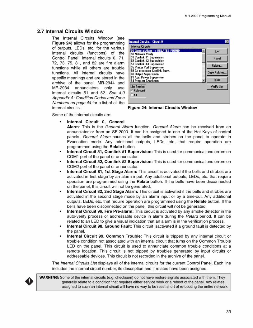
MR-2900 Programming Manual
2.7 Internal Circuits WindowThe Internal Circuits Window (seeFigure 24) allows for the programmingof outputs, LEDs, etc. for the variousinternal circuits (functions) of theControl Panel. Internal circuits 0, 71,72, 73, 75, 81, and 82 are fire alarmfunctions while all others are troublefunctions. All internal circuits havespecific meanings and are stored in thearchive of the panel. MR-2944 andMR-2934 annunciators only useinternal circuits 51 and 52. See 4.0Appendix A: Condition Codes and ZoneNumbers on page 44 for a list of all theinternal circuits.
Some of the internal circuits are:
• Internal Circuit 0, GeneralAlarm: This is the General Alarm function. General Alarm can be received from anannunciator or from an SE 2000. It can be assigned to one of the Hot Keys of controlpanels. General Alarm causes all the bells and strobes on the panel to operate inEvacuation mode. Any additional outputs, LEDs, etc. that require operation areprogrammed using the Relate button.
• Internal Circuit 51, Comlink #1 Supervision: This is used for communications errors onCOM1 port of the panel or annunciator.
• Internal Circuit 52, Comlink #2 Supervision: This is used for communications errors onCOM2 port of the panel or annunciator.
• Internal Circuit 81, 1st Stage Alarm: This circuit is activated if the bells and strobes areactivated in first stage by an alarm input. Any additional outputs, LEDs, etc. that requireoperation are programmed using the Relate button. If the bells have been disconnectedon the panel, this circuit will not be generated.
• Internal Circuit 82, 2nd Stage Alarm: This circuit is activated if the bells and strobes areactivated in the second stage mode by an alarm input or by a time-out. Any additionaloutputs, LEDs, etc. that require operation are programmed using the Relate button. If thebells have been disconnected on the panel, this circuit will not be generated.
• Internal Circuit 96, Fire Pre-alarm: This circuit is activated by any smoke detector in theauto-verify process or addressable device in alarm during the Retard period. It can berelated to an LED to give a visual indication that an alarm is in the verification process.
• Internal Circuit 98, Ground Fault: This circuit isactivated if a ground fault is detected bythe panel.
• Internal Circuit 99, Common Trouble: This circuit is tripped by any internal circuit ortrouble condition not associated with an internal circuit that turns on the Common TroubleLED on the panel. This circuit is used to annunciate common trouble conditions at aremote location. This circuit is not tripped by troubles generated by input circuits oraddressable devices. This circuit is not recorded in the archive of the panel.
The Internal Circuits List displays all of the internal circuits for the current Control Panel. Each lineincludes the internal circuit number, its description and if relates have been assigned.
WARNING: Some of the internal circuits (e.g. checksum) do not have restore signals associated with them. They generally relate to a condition that requires either service work or a reboot of the panel. Any relates assigned to such an internal circuit will have no way to be reset short of re-booting the entire network.
Figure 24: Internal Circuits Window
33
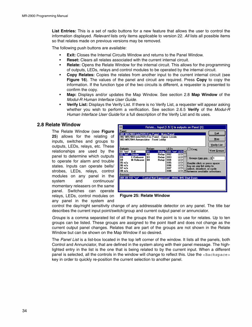
MR-2900 Programming Manual
List Entries: This is a set of radio buttons for a new feature that allows the user to control theinformation displayed. Relevant lists only items applicable to version 22. All lists all possible itemsso that relates made on previous versions may be removed.
The following push buttons are available:
• Exit: Closes the Internal Circuits Window and returns to the Panel Window.• Reset: Clears all relates associated with the current internal circuit.• Relate: Opens the Relate Window for the internal circuit. This allows for the programming
of outputs, LEDs, relays and control modules to be operated by the internal circuit.• Copy Relates: Copies the relates from another input to the current internal circuit (see
Figure 16). The values of the panel and circuit are required. Press Copy to copy theinformation. If the function type of the two circuits is different, a requester is presented toconfirm the copy.
• Map: Displays and/or updates the Map Window. See section 2.8 Map Window of theModul-R Human Interface User Guide.
• Verify List: Displays the Verify List. If there is no Verify List, a requester will appear askingwhether you wish to perform a verification. See section 2.6.5 Verify of the Modul-RHuman Interface User Guide for a full description of the Verify List and its uses.
2.8 Relate WindowThe Relate Window (see Figure25) allows for the relating ofinputs, switches and groups tooutputs, LEDs, relays, etc. Theserelationships are used by thepanel to determine which outputsto operate for alarm and troublestates. Inputs can operate bells/strobes, LEDs, relays, controlmodules on any panel in thesystem and continuous/momentary releasers on the samepanel. Switches can operaterelays, LEDs, control modules onany panel in the system andcontrol the day/night sensitivity change of any addressable detector on any panel. The title bardescribes the current input point/switch/group and current output panel or annunciator.
Groups is a comma separated list of all the groups that the point is to use for relates. Up to tengroups can be listed. These groups are assigned to the point itself and does not change as thecurrent output panel changes. Relates that are part of the groups are not shown in the RelateWindow but can be shown on the Map Window if so desired.
The Panel List is a list-box located in the top left corner of the window. It lists all the panels, bothControl and Annunciator, that are defined in the system along with their panel message. The high-lighted entry in the list is the one that is being related to by the current input. When a differentpanel is selected, all the controls in the window will change to reflect this. Use the <Backspace>key in order to quickly re-position the current selection to another panel.
Figure 25: Relate Window
34
MR-2900 Programming Manual
The Outputs List shows the programmable outputs of the panel. It is not shown for annunciators. Itlists all outputs, along with their definition and current state. The states are *on* for selected, blankfor not selected, act if they are activated by default, and n/a for not available. A blank definition isfor unused outputs. Bell and Strobe outputs can only be selected for Fire Alarm type inputs. IfComplex Releasers are enabled, releasers can have three other states: Fast which operates thereleaser immediately regardless of any delay that is programmed in; *A* or *B* which allow forAND logic. The releaser will not operate until both an A and a B input have been activated. Use the<space> key or double click on the entry to cycle between available selections. Use the<Backspace> key in order to quickly re-position the current selection to another output.
The Relays List shows the general purpose function relays of the panel. It is not shown forannunciators. Each is listed by number and state. The states are *on* for selected and blank fornot selected. Use the <space> key or double click on the entry to cycle between availableselections. Use the <Backspace> key in order to quickly re-position the current selection toanother relay.
The LEDs List shows the LED zones available on the panel or annunciator. This will not be shownif the panel has no LEDs. Each is listed by number and state. The states are *on* for selected,blank for not selected and n/a for not available. Use the <space> key or double click on the entryto cycle between available selections. Use the <Backspace> key in order to quickly re-positionthe current selection to another LED. The actual number of LED zones varies depending upon thepanel or annunciator.
The Device List shows the addressable devices that can be related to the current point. Forsystem inputs and groups, it is displayed only if there are any control or relay modules defined forthe panel; for switches, it is displayed if there are any addressable detectors, or any control orrelay modules defined. Each entry shows the devices’s address (panel. circuit.device), its stateand its device message. The states are *on* for selected and blank for not selected. If ComplexReleasers are enabled, control modules programmed for releasers can have three other states:Fast which operates the releaser immediately regardless of any delay that is programmed in; *A*or *B* which allow for AND logic. The releaser will not operate until both an A and a B input havebeen activated. Devices that are not available or are invalid are not shown. Use the <space> keyor double click on the entry to cycle between available selections.
The Evac check box is an option for Fire Alarm type inputs only. Selecting this option will cause allBells and Strobes for this panel to operate in Second Stage (Evacuation) mode. If selected, Belland Strobe type outputs for this panel will not be selectable. This will not affect the Bell and Strobeselection of other panels.
The Msg Receive check box is an option for annunciators with LCDs only. If marked, thisannunciator will receive messages about this input point to display in its Alarm List. If not marked,the annunciator will not receive messages about this input point to display in its Alarm List.
The push buttons, located on the right side of the window, are:
• Exit: Closes the Relate Window and returns to the previous window.• Map: Displays and/or updates the Map Window. See section 2.8 Map Window of the
Modul-R Human Interface User Guide.• Verify List: Displays the Verify List. If there is no Verify List, a requester will appear asking
whether you wish to perform a verification. See section 2.6.5 Verify of the Modul-RHuman Interface User Guide for a full description of the Verify List and its uses.
• View Groups: Displays the Groups Window. This is for reviewing the defined groups. Noediting can be done to the groups. To edit the groups, return to the System Window. Seesection 2.4 Groups Window.
35
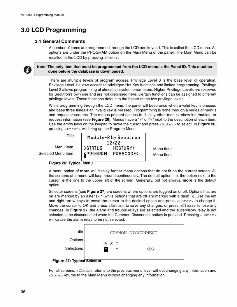
MR-2900 Programming Manual
3.0 LCD Programming
3.1 General CommentsA number of items are programmed through the LCD and keypad. This is called the LCD menu. Alloptions are under the PROGRAM option on the Main Menu of the panel. The Main Menu can berecalled to the LCD by pressing <Home>.
There are multiple levels of program access. Privilege Level 0 is the base level of operation.Privilege Level 1 allows access to privileged Hot Key functions and limited programming. PrivilegeLevel 2 allows programming of almost all system parameters. Higher Privilege Levels are reservedfor Secutron's own use and are not discussed here. Certain functions can be assigned to differentprivilege levels. These functions default to the higher of the two privilege levels.
While programming through the LCD menu, the panel will beep once when a valid key is pressedand beep three times if an invalid key is pressed. Programming is done through a series of menusand requester screens. The menus present options to display other menus, show information, orrequest information (see Figure 26). Menus have a ">" or "<" next to the description of each item.Use the arrow keys on the keypad to move the cursor and press <Enter> to select. In Figure 26,pressing <Enter> will bring up the Program Menu.
A menu option of more will display further menu options that do not fit on the current screen. Allthe screens of a menu will loop around continuously. The default option, i.e. the option next to thecursor, is the one to the upper left of the screen. Generally, but not always, more is the defaultoption.
Selector screens (see Figure 27) are screens where options are toggled on or off. Options that areon are marked by an asterisk(*) while options that are off are marked with a dash (-). Use the leftand right arrow keys to move the cursor to the desired option and press <Enter> to change it.Move the cursor to OK and press <Enter> to save any changes, or press <Clear> to lose anychanges. In Figure 27, the alarm and trouble relays are selected and the supervisory relay is notselected to be disconnected when the Common Disconnect hotkey is pressed. Pressing <Enter>will cause the alarm relay to be not selected.
For all screens, <Clear> returns to the previous menu level without changing any information and<Home> returns to the Main Menu without changing any information.
Note: The only item that must be programmed from the LCD menu is the Panel ID. This must be done before the database is downloaded.
Module-R by Secutron12:22
>STATUS HISTORY<>PROGRAM PASSCODE<
Title
Menu Item
Selected Menu Item Menu Item
Menu Item
Figure 26: Typical Menu
Title
Options
Selections
COMMON DISCONNECT
A S T* - * OK<
Figure 27: Typical Selector
36
MR-2900 Programming Manual
3.2 ClockThis menu has the following options:
• Date: View or change the date. The date is entered in MM.DD.YY format. Each section ofthe date must be separated by a dot. Press <Enter> to accept date typed. <Clear> willremove any digits typed. If no digits are displayed, <Clear> will return to the Clock Menu.The new date will be sent to all other panels on the Network, if used. All panels willassume this date. The date change will be recorded in the Archive.
• Time: Change the time. The time is entered in HH.MM.SS format. Each section of thetime must be separated by a dot. All times are in 24 hour format. Press <Enter> to accepttime typed. <Clear> will remove any digits typed. If no digits are displayed, <Clear> willreturn to the Clock Menu. The new time will be sent to all other panels on the Network, ifused. All panels will assume this time. If <Enter> is pressed with no time entered, thecurrent time will be sent to all panels on the network. If a change of greater than 5 minutesoccurs, the new time will be recorded in the archive.
• Calibrate: Calibrates the clock so that it keeps correct time. Calibration takes 2 to 45days. Waiting longer will give more accurate results. The panel will function normally whilecalibrating. When sufficient time has passed, re-selecting this function will ask for thecorrect time. The calibration will then be reported. In a network, only the master panelneeds to be calibrated.
3.3 Common RelaysThis function is restricted to Privilege Level 2. The menu has the following options:
• Disconnect: View or change the relays that can be disconnected by the CommonDisconnect hot key. Selected relays will be marked by an asterisk (*). To change theselection, move the cursor to the desired relay A(larm), S(upervisory) or T(rouble) andpress <Enter> to change. Select OK when done. <Clear> will return to Program Menuwithout making changes.
• Test Inhibit: View or change whether common relays are disconnected during Test Modeor not. <Clear> will return to Program Menu without making changes.
3.4 SwitchesThis function can be set to Privilege Level 1 or 2. View or change the status of any switches.These switches can be set to On, Off or Auto. The Auto state only applies to switches that have atimer associated with them. The Auto state allows the switch to follow the timer settings. Anychanges made are broadcast to the network so that all panels have the same state. Settings areretained by the panel if it is re-booted and the Master Unit will broadcast its settings to the networkupon start up. See section 2.3 Switches Window for information on programming what the switchaffects.
The menu has the following options:
• Individual: View or change the status of an individual switch. Each switch will be shown inturn. If a switch has no timer, the Auto option is not shown.
• All Off: Force switches into the Off mode. The number displayed is the number of timersthat are switched On. This option is shown only if no switches have timers associated withthem.
Notes: 1. The Master Panel in a network will synchronize all clocks in the network at 03:30 every day, sending both date and time.
2. Changing the time while the panel is calibrating will abort the calibration.
Note: Changing the time using the Time option will abort the calibration. If a panel is currently in a calibration, it will ignore time changes sent over the network.
37
MR-2900 Programming Manual
• All Auto: Force all switches with timers to Auto mode. All switches with timers will go intothe state dictated by the time. The number displayed is the number of switches with timersforced On or Off. This option has no effect on switches without timers. This option is notshown if no timers are associated with the switches.
3.5 BatteryDisplays the current battery status and charger calibration. The display shows:
Line 1: Screen TitleLine 2: AC State and Battery Charger Calibration Numbers (diagnostic use only)Line 3: Current State of the Battery and Menu Option (see below)Line 4: Menu Options (listed below)The menu has the following options:
• OK: Return to Program Menu.• Calibrate: This function is restricted to Privilege Level 2. This calibrates the Battery
Charger. The batteries must be disconnected before beginning calibration. No keypadcontrol is provided during calibration. The calibration display will return when calibration isover. Calibration only needs to be done when the main circuit board/power supply boardpair is changed, or when the configuration is erased. All Battery Chargers come calibratedfrom the factory.
• Test: Force an immediate battery test.
3.6 ConventionalThis menu provides for the testing and bypassing of conventional circuits. Each function willpresent each zone in turn for selection. Press <Clear> to return to this menu without makingchanges. The menu has the following options:
• Test: Select which zones to test. Test Mode must be on to select zones for testing. Allzones selected are automatically deselected when Test Mode is turned off.
• Bypass: This function can be set to Privilege Level 1 or 2. Select conventional circuits tobypass. A bypassed circuit will be ignored by the panel. Bypasses are retained when thepanel is re-booted. Bypasses are annunciated by a common trouble condition.
3.7 Addressable
The menu has the following options1:
• Reset Max/Min: Clears the stored values for the maximum and minimum values returnedby the addressable devices. These values are automatically cleared when the panelreboots.
• Duplicates Check: This will cause an immediate check to see if more than one device isusing an address. The panel automatically does this check on the hour.
• LED Mode: This controls how the LEDs on the devices are used. There are three options:-- OFF/FLASH: The device LEDs are normally off and will flash when an alarm is reported.
The flashing LED will be reset when System Reset is pressed.
-- FLASH/ON: The device LEDs flash each time they are polled. They will latch on inAlarm. The LEDs will be reset when System Reset is pressed.
1. Panels with 64K EEPROM will not retain Bypass, Sensitivity or Control Module forced states when restarted.a. BRK programs dated before 2 April 1999 limit the number of LEDs on to 3 per circuit.
Note: Due to current draw limitations, only the first 5 detectorsa on a circuit will latch their LEDs. This has no effect on other panel operation.
38
MR-2900 Programming Manual
-- OFF/ON: The LEDs are normally off and will latch on in Alarm. The LEDs will be resetwhen System Reset is pressed. This option will not be shown if the addressable co-processor cannot support this mode.
-- RESET: This functions resets the LEDs to their off state.
• Sensitivity: This function is restricted to Privilege Level 2. This allows for the manualadjustment of the sensitivity of addressable detectors. All devices have a defaultsensitivity assigned in the database. The detector can be set to the database default valueor to one of the pre-defined levels replacing the database values. These manual valuesare retained if the panel is re-booted.-- SELECT: Change the manual sensitivity of addressable detectors. The first screen asks
for a circuit and device number. Enter the circuit and device or press <Enter> withoutentering any number to view the first detector in the database. Each detector will bedisplayed in turn, showing the current sensitivity and allowing for it to be changed or thenext detector to be displayed. Press <Clear> to stop viewing the detector list.
-- PRINT: Print a list of all detectors that have a sensitivity other than the one selected inthe database. This option is not shown if no manual sensitivities have been set.
-- ALL DEFAULT: Change all manual sensitivity settings to the default values set in thedatabase.
• Monitor: Allows you to select between all Class A monitor modules and individuallyselected ones in MHI.
• Bypass: This function can be set to Privilege Level 1 or 2. This selects devices to bebypassed. A bypassed device will be ignored by the system. Addressable bypasses areretained when the panel is re-booted. Only devices included in the database can bebypassed. Bypasses are annunciated by a common trouble condition. The Bypass menuhas the following options:-- ON: Select devices to be bypassed. Enter the circuit and device number. Press<Enter> to accept the device and to enter the next one. Pressing <Clear> willremove any numbers entered. Pressing either <Enter> or <Clear> with no numbersdisplayed will end the input mode.
-- OFF: Select bypassed devices to be returned to normal operation. Each bypasseddevice is listed in order. Select next to keep the bypass on or select OFF to remove thebypass. After the last device, display returns to the Bypass menu. Press <Clear> toreturn to the Bypass Menu. This option is not available if there are no devicesbypassed.
-- ALL OFF: Remove all bypasses, if any, from the system. The number of bypasseddevices is displayed next to this option.
• Test: Select devices to be tested. Test Mode must be active for this selection to beavailable. All devices selected for testing are automatically deselected when Test Mode isturned off. The Test Menu has the following options:-- ON: Select devices for testing. Enter the circuit and device number, or enter the circuit
number only to select all devices on the circuit. Press <Enter> to accept the deviceand to enter the next one. Pressing <Clear> will remove any numbers entered.Pressing either <Enter> or <Clear> with no numbers displayed will end the inputmode.
Note: Due to current draw limitations, only the first 5 detectors on a circuit will latch their LEDs. This has no effect on other panel operation.
39
MR-2900 Programming Manual
-- OFF: Select devices under test to be returned to normal operation. Each device undertest is listed in order. Select next to keep the device under test or select OFF to removethe test mode. After the last device, display returns to the Test menu. Press <Clear> toreturn to the Test Menu. This option is not available if there are no devices selected fortesting.
-- ALL OFF: Remove all devices being tested, if any, from the test mode. The number ofdevices being tested is displayed next to this option.
• Control Modules: This function can be set to Privilege Level 1 or 2. Allow for the manualoperation of the control and relay modules included in the database. There are threestates available: Automatic (controlled by device inputs), Manual On, and Manual Off. Thismode is retained if the panel is re-booted. Manually controlled modules are annunciatedby a common trouble condition. The menu has the following options:-- SELECT: Change the Auto/On/Off state of control modules. The first screen asks for a
circuit and device number. Enter the circuit and device or press <Enter> withoutentering any number to view the first control module in the database. Each controlmodule will be displayed in turn, showing the current state and allowing for it to bechanged or the next control module to be displayed. Press <Clear> to stop viewing thecontrol module list.
-- ALL AUTO: Change any control modules that are forced on or off back to automaticmode.
3.8 ArchiveThis function is restricted to Privilege Level 2. View and change the settings for the recording ofoptional entries into the history. The following items can be included or not included in the history:
• Test: View or change whether Test signals should be recorded in the history. The currentsetting is shown in the upper right corner. Test signals will be marked as such.
• Non-Reporting: View or change whether non-reporting signals are recorded in the historyor not. Non-reporting signals are recorded by default.
• Network: Local causes only the local panel’s events to be stored in its archive. Globalcauses all panel’s events to be stored in this panel’s archive. This option is shown only forthe master panel in a network.
3.9 RelaysThis function can be set to Privilege Level 1 or 2. This function allows for the manual operation ofthe relays. There are three possible states: Automatic (state determined by inputs), Forced On, orForced Off. This mode will be retained if the panel is re-booted.
• Individual: Change the Auto/On/Off state of relay. Each relay will show the current stateand allow it to be changed or the next relay to be displayed. Press <Clear> to stopviewing the relay list.
• All Auto: Change any relays that are forced on or off back to automatic mode. Thenumber after All Auto is the number of relays in a forced on or off state.
3.10 PortsThis menu has the following options:
• Network: Allows for the setting of parameters related to the network. If the downloadeddatabase indicates that there is no network, the only option is Panel ID. The NetworkMenu has the following options:-- Panel ID: This function is restricted to Privilege Level 2. Set the Network ID number.
This is between 1 and 254.
40
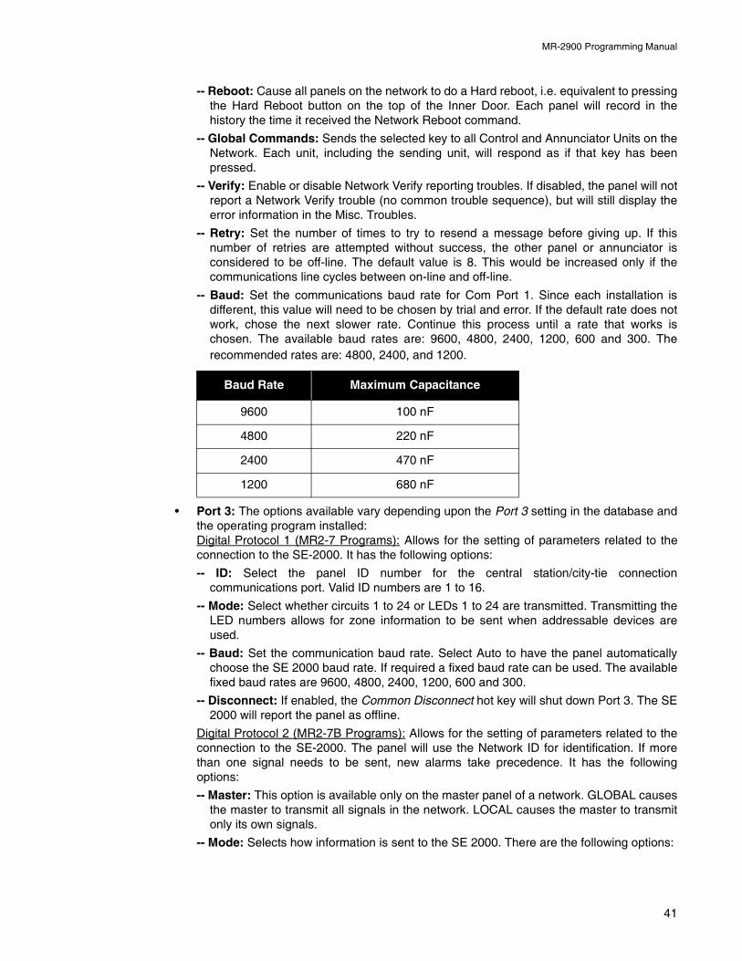
MR-2900 Programming Manual
-- Reboot: Cause all panels on the network to do a Hard reboot, i.e. equivalent to pressingthe Hard Reboot button on the top of the Inner Door. Each panel will record in thehistory the time it received the Network Reboot command.
-- Global Commands: Sends the selected key to all Control and Annunciator Units on theNetwork. Each unit, including the sending unit, will respond as if that key has beenpressed.
-- Verify: Enable or disable Network Verify reporting troubles. If disabled, the panel will notreport a Network Verify trouble (no common trouble sequence), but will still display theerror information in the Misc. Troubles.
-- Retry: Set the number of times to try to resend a message before giving up. If thisnumber of retries are attempted without success, the other panel or annunciator isconsidered to be off-line. The default value is 8. This would be increased only if thecommunications line cycles between on-line and off-line.
-- Baud: Set the communications baud rate for Com Port 1. Since each installation isdifferent, this value will need to be chosen by trial and error. If the default rate does notwork, chose the next slower rate. Continue this process until a rate that works ischosen. The available baud rates are: 9600, 4800, 2400, 1200, 600 and 300. Therecommended rates are: 4800, 2400, and 1200.
• Port 3: The options available vary depending upon the Port 3 setting in the database andthe operating program installed:Digital Protocol 1 (MR2-7 Programs): Allows for the setting of parameters related to theconnection to the SE-2000. It has the following options:
-- ID: Select the panel ID number for the central station/city-tie connectioncommunications port. Valid ID numbers are 1 to 16.
-- Mode: Select whether circuits 1 to 24 or LEDs 1 to 24 are transmitted. Transmitting theLED numbers allows for zone information to be sent when addressable devices areused.
-- Baud: Set the communication baud rate. Select Auto to have the panel automaticallychoose the SE 2000 baud rate. If required a fixed baud rate can be used. The availablefixed baud rates are 9600, 4800, 2400, 1200, 600 and 300.
-- Disconnect: If enabled, the Common Disconnect hot key will shut down Port 3. The SE2000 will report the panel as offline.
Digital Protocol 2 (MR2-7B Programs): Allows for the setting of parameters related to theconnection to the SE-2000. The panel will use the Network ID for identification. If morethan one signal needs to be sent, new alarms take precedence. It has the followingoptions:
-- Master: This option is available only on the master panel of a network. GLOBAL causesthe master to transmit all signals in the network. LOCAL causes the master to transmitonly its own signals.
-- Mode: Selects how information is sent to the SE 2000. There are the following options:
Baud Rate Maximum Capacitance
9600 100 nF
4800 220 nF
2400 470 nF
1200 680 nF
41
MR-2900 Programming Manual
DEVICE (default): Send the device address or internal circuit number withouttranslation.
ZONE: Send the LED number turned on for input circuits and devices and send theinternal circuit for internal circuits.
GROUP: Send the associated Group ID(s) for all conditions. Anything not associatedwith a specific group will send a group number of 0.
-- Baud: Set the communications baud rate. Enter a value of 0 (zero) to have the panel toautomatically choose the SE 2000 baud rate. If required a fixed baud rate can be used.The available fixed baud rates are 9600, 4800, 2400, 1200, 600 and 300.
-- Disconnect: If enabled, the Common Disconnect hot key will shut down Port 3. The SE2000 will report the panel as offline.
PC Connect (MR2-7G Programs): Allows for the configuration of the communications to aGRID package. If more than one signal needs to be sent, new alarms take precedence.
-- ON/OFF: Allows for enabling or disabling of the port. The master panel will report for allpanels in the network.
-- Baud: Sets the communications baud rate. The available fixed baud rates are 9600,4800, 2400, 1200, 600 and 300.
-- Delay: Sets the length of time the panel will wait before reporting the GRID package off-line. This can be set from 10 to 255 seconds.
-- Disconnect: If enabled, the Common Disconnect hot key will shut down Port 3. TheGRID package will report the panel as offline.
Annunciator Connect (MR2-7A Programs): Allows for the configuration of thecommunications to MR-2614, MR-2644, MR-2801-MR and Dialler.
-- Baud: Sets the communications baud rate. The available fixed baud rates are 4800 and
1200.1
Voice Evac. System (MR2-7E Programs): Allows for setting parameters related to theconnection to the MV2700 voice evacuation panel.
-- Mode: Selects how information is sent to the MV2700. There are the following options:DEVICE (default): Send the device address or internal circuit number without
translation.ZONE: Send the LED number turned on for input circuits and devices and send the
internal circuit for internal circuits.GROUP: Send the associated Group ID(s) for all conditions. Anything not associated
with a specific group will send a group number of 0.
-- Retry: Set the number of times to try to resend a message before giving up. If thisnumber of retries are attempted without success, the other panel is considered to beoff-line. The default value is 8. This would be increased only if the communications linecycles between on-line and off-line. (Range: 2 – 99)
-- Disconnect: If enabled, the Common Disconnect hot key will shut down Port 3.
-- Baud: Set the communications baud rate. The available fixed baud rates are 9600,4800, 2400, 1200, 600 and 300.
• Terminal: Select ANSI or TeleVideo protocol. Most terminals and terminal emulatorprograms support ANSI protocol.
• Printer: MR1-1 and MRx-2 Programs: Select the baud rate for the printer port. Theavailable rates are 9600 (default), 4800, 2400, 1200, 600, and 300.MRx-3 and MRx-7 Programs: There are two options for configuring the Port 6 serial printerport:
1. Only MR-2614 v2.1 and up support 4800 baud. Previous versions only support 1200 baud.
42
MR-2900 Programming Manual
-- Size: Set the width of the lines sent to the Port 6 printer or disable the printer. Optionsare None, 20 and 80. The default is None, which disables this feature. Use 20 whenusing an MR-2920 printer.
-- Baud: Select the baud rate for the printer port if the size is 80 columns. The availablerates are 9600 (default), 4800, 2400, 1200, 600, and 300.
3.11 Alarm ListThis menu controls the operation of the Alarm List. This function is restricted to Privilege Level 2. Ithas the following options:
• Reset: Select when entries are taken out of the Alarm List. AUTO removes entries assoon as the condition restores. MANUAL requires that Reset be pressed before they areremoved. Conditions that have restored will be shown as a restored condition in the AlarmList.
• Remote: Routes the messages for events from the panel to annunciators. The optionsare:-- ALL: All messages are sent to all annunciators.
-- SELECT: Messages are sent as directed in the database.
3.12 PasscodeAllows for the changing of passcodes. The Privilege Level 2 can change both the Level 1 and 2passcodes, while Level 1 can only change the Level 1 passcode. Passcodes are four digitnumbers in the range 1000 to 9999. Type in the new passcode and press <Enter> to accept.Asterisks will be displayed instead of the numbers. <Clear> will remove any digits typed. If nodigits are displayed, <Clear> will return to the Program or Passcode Menu.
The default Level 2 passcode is 2222. The default Level 1 passcode is 1111. These passcodesshould be changed to prevent unauthorized access.
There is a special Level 2 passcode that is variable from day to day. It can be obtained fromSecutron if the Level 2 passcode is forgotten.
3.13 MemoryThis function is restricted to Privilege Level 2. This menu has the following options:
• Erase Configuration: This will erase all initiating circuit, bell, relay, releaser and privilegevalues entered from the keypad and LCD menu, and replace them with default values.With MR2 programs, this has no effect on information contained in the downloadeddatabase. Confirmation is asked before erasure. After the Configuration has been erased,the panel must be reset using the reset button at the top of the Main Circuit Board, if thepanel does not do this automatically. The following items are not erased: Serial Number,Clock Calibration, Level 1 Passcode, Level 2 Passcode, Main Board Type, Terminal BoardType, Input Circuit Modules.
3.14 BuzzerThis function is restricted to Privilege Level 2. This sets the length of the Trouble Buzzer Inhibittime. This is the length of time that a new trouble will not cause the buzzer to sound after it hasbeen silenced for a trouble. The time can be set to 0 or from 15 to 255 seconds. If 0 is chosen, thebuzzer will sound for every trouble.
Note: The battery charger will need to be re-calibrated (see Section 3.5, page 39) after erasing the configuration.
43
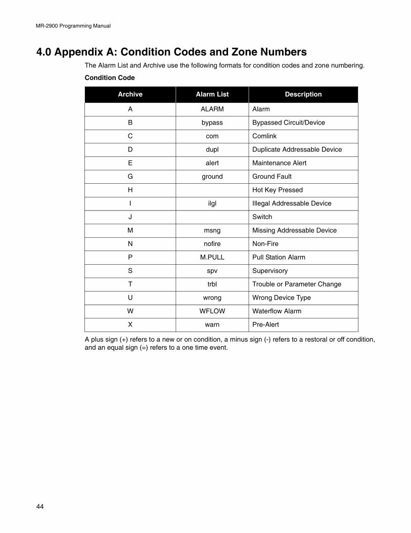
MR-2900 Programming Manual
4.0 Appendix A: Condition Codes and Zone NumbersThe Alarm List and Archive use the following formats for condition codes and zone numbering.
Condition Code
A plus sign (+) refers to a new or on condition, a minus sign (-) refers to a restoral or off condition,and an equal sign (=) refers to a one time event.
Archive Alarm List Description
A ALARM Alarm
B bypass Bypassed Circuit/Device
C com Comlink
D dupl Duplicate Addressable Device
E alert Maintenance Alert
G ground Ground Fault
H Hot Key Pressed
I ilgl Illegal Addressable Device
J Switch
M msng Missing Addressable Device
N nofire Non-Fire
P M.PULL Pull Station Alarm
S spv Supervisory
T trbl Trouble or Parameter Change
U wrong Wrong Device Type
W WFLOW Waterflow Alarm
X warn Pre-Alert
44
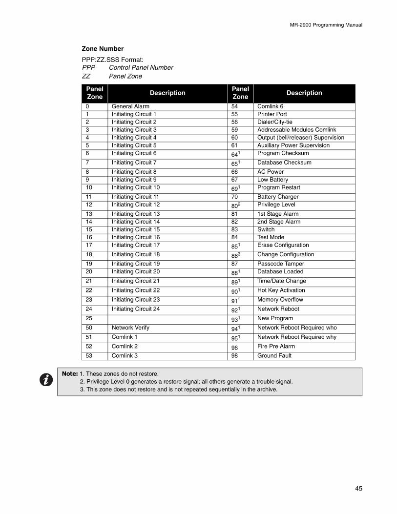
MR-2900 Programming Manual
Zone Number
PPP:ZZ.SSS Format:PPP Control Panel NumberZZ Panel Zone
Panel Zone
DescriptionPanel Zone
Description
0 General Alarm 54 Comlink 61 Initiating Circuit 1 55 Printer Port2 Initiating Circuit 2 56 Dialer/City-tie3 Initiating Circuit 3 59 Addressable Modules Comlink4 Initiating Circuit 4 60 Output (bell/releaser) Supervision5 Initiating Circuit 5 61 Auxiliary Power Supervision6 Initiating Circuit 6 641 Program Checksum
7 Initiating Circuit 7 651 Database Checksum
8 Initiating Circuit 8 66 AC Power9 Initiating Circuit 9 67 Low Battery10 Initiating Circuit 10 691 Program Restart
11 Initiating Circuit 11 70 Battery Charger12 Initiating Circuit 12 802 Privilege Level
13 Initiating Circuit 13 81 1st Stage Alarm14 Initiating Circuit 14 82 2nd Stage Alarm15 Initiating Circuit 15 83 Switch16 Initiating Circuit 16 84 Test Mode17 Initiating Circuit 17 851 Erase Configuration
18 Initiating Circuit 18 863 Change Configuration
19 Initiating Circuit 19 87 Passcode Tamper20 Initiating Circuit 20 881 Database Loaded
21 Initiating Circuit 21 891 Time/Date Change
22 Initiating Circuit 22 901 Hot Key Activation
23 Initiating Circuit 23 911 Memory Overflow
24 Initiating Circuit 24 921 Network Reboot
25 931 New Program
50 Network Verify 941 Network Reboot Required who
51 Comlink 1 951 Network Reboot Required why
52 Comlink 2 96 Fire Pre Alarm
53 Comlink 3 98 Ground Fault
Note: 1. These zones do not restore.2. Privilege Level 0 generates a restore signal; all others generate a trouble signal.3. This zone does not restore and is not repeated sequentially in the archive.
45
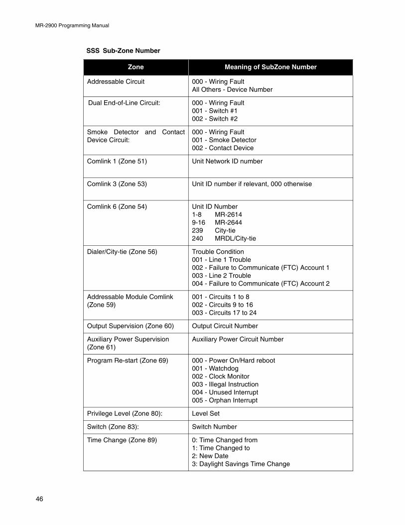
MR-2900 Programming Manual
SSS Sub-Zone Number
Zone Meaning of SubZone Number
Addressable Circuit 000 - Wiring FaultAll Others - Device Number
Dual End-of-Line Circuit: 000 - Wiring Fault001 - Switch #1002 - Switch #2
Smoke Detector and ContactDevice Circuit:
000 - Wiring Fault001 - Smoke Detector002 - Contact Device
Comlink 1 (Zone 51) Unit Network ID number
Comlink 3 (Zone 53) Unit ID number if relevant, 000 otherwise
Comlink 6 (Zone 54) Unit ID Number1-8 MR-26149-16 MR-2644239 City-tie240 MRDL/City-tie
Dialer/City-tie (Zone 56) Trouble Condition001 - Line 1 Trouble002 - Failure to Communicate (FTC) Account 1003 - Line 2 Trouble004 - Failure to Communicate (FTC) Account 2
Addressable Module Comlink (Zone 59)
001 - Circuits 1 to 8002 - Circuits 9 to 16003 - Circuits 17 to 24
Output Supervision (Zone 60) Output Circuit Number
Auxiliary Power Supervision (Zone 61)
Auxiliary Power Circuit Number
Program Re-start (Zone 69) 000 - Power On/Hard reboot001 - Watchdog002 - Clock Monitor003 - Illegal Instruction004 - Unused Interrupt005 - Orphan Interrupt
Privilege Level (Zone 80): Level Set
Switch (Zone 83): Switch Number
Time Change (Zone 89) 0: Time Changed from1: Time Changed to2: New Date3: Daylight Savings Time Change
46
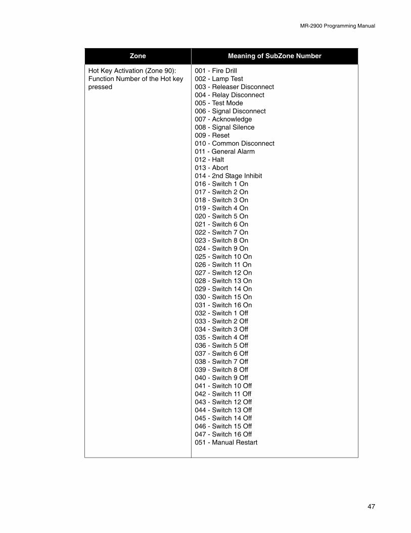
MR-2900 Programming Manual
Hot Key Activation (Zone 90): Function Number of the Hot key pressed
001 - Fire Drill002 - Lamp Test003 - Releaser Disconnect004 - Relay Disconnect005 - Test Mode006 - Signal Disconnect007 - Acknowledge008 - Signal Silence009 - Reset010 - Common Disconnect011 - General Alarm012 - Halt013 - Abort014 - 2nd Stage Inhibit016 - Switch 1 On017 - Switch 2 On018 - Switch 3 On019 - Switch 4 On020 - Switch 5 On021 - Switch 6 On022 - Switch 7 On023 - Switch 8 On024 - Switch 9 On025 - Switch 10 On026 - Switch 11 On027 - Switch 12 On028 - Switch 13 On029 - Switch 14 On030 - Switch 15 On031 - Switch 16 On032 - Switch 1 Off033 - Switch 2 Off034 - Switch 3 Off035 - Switch 4 Off036 - Switch 5 Off037 - Switch 6 Off038 - Switch 7 Off039 - Switch 8 Off040 - Switch 9 Off041 - Switch 10 Off042 - Switch 11 Off043 - Switch 12 Off044 - Switch 13 Off045 - Switch 14 Off046 - Switch 15 Off047 - Switch 16 Off051 - Manual Restart
Zone Meaning of SubZone Number
47
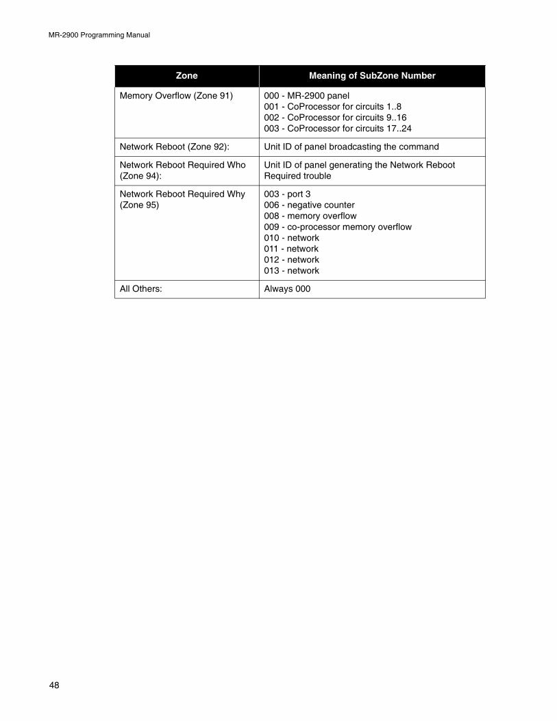
MR-2900 Programming Manual
Memory Overflow (Zone 91) 000 - MR-2900 panel001 - CoProcessor for circuits 1..8002 - CoProcessor for circuits 9..16003 - CoProcessor for circuits 17..24
Network Reboot (Zone 92): Unit ID of panel broadcasting the command
Network Reboot Required Who (Zone 94):
Unit ID of panel generating the Network Reboot Required trouble
Network Reboot Required Why (Zone 95)
003 - port 3006 - negative counter008 - memory overflow009 - co-processor memory overflow010 - network011 - network012 - network013 - network
All Others: Always 000
Zone Meaning of SubZone Number
48
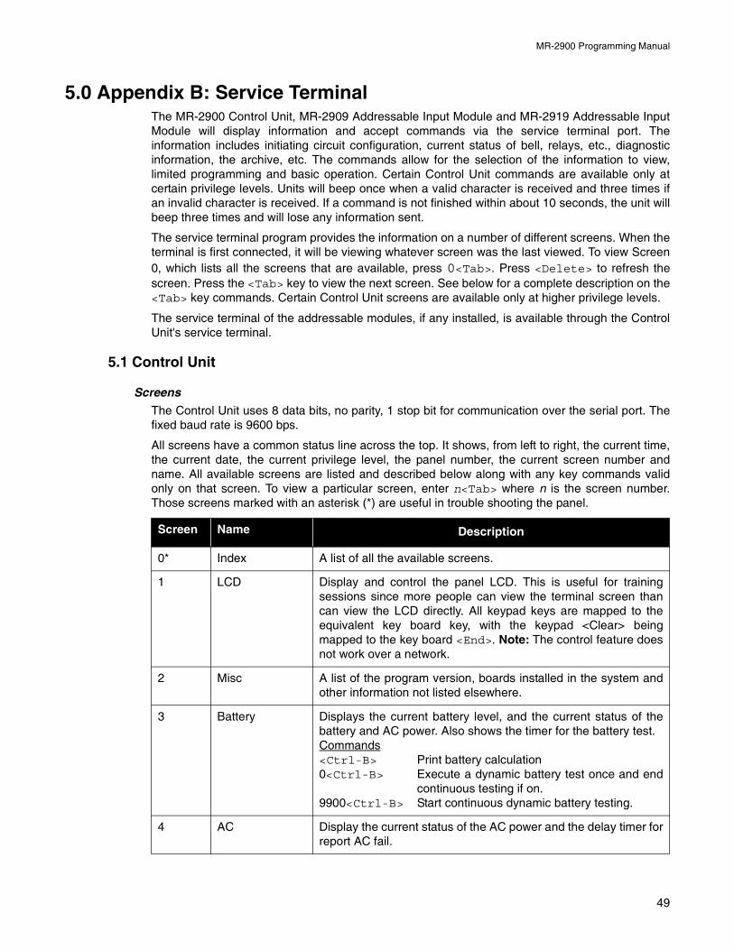
MR-2900 Programming Manual
5.0 Appendix B: Service TerminalThe MR-2900 Control Unit, MR-2909 Addressable Input Module and MR-2919 Addressable InputModule will display information and accept commands via the service terminal port. Theinformation includes initiating circuit configuration, current status of bell, relays, etc., diagnosticinformation, the archive, etc. The commands allow for the selection of the information to view,limited programming and basic operation. Certain Control Unit commands are available only atcertain privilege levels. Units will beep once when a valid character is received and three times ifan invalid character is received. If a command is not finished within about 10 seconds, the unit willbeep three times and will lose any information sent.
The service terminal program provides the information on a number of different screens. When theterminal is first connected, it will be viewing whatever screen was the last viewed. To view Screen0, which lists all the screens that are available, press 0<Tab>. Press <Delete> to refresh thescreen. Press the <Tab> key to view the next screen. See below for a complete description on the<Tab> key commands. Certain Control Unit screens are available only at higher privilege levels.
The service terminal of the addressable modules, if any installed, is available through the ControlUnit's service terminal.
5.1 Control Unit
Screens
The Control Unit uses 8 data bits, no parity, 1 stop bit for communication over the serial port. Thefixed baud rate is 9600 bps.
All screens have a common status line across the top. It shows, from left to right, the current time,the current date, the current privilege level, the panel number, the current screen number andname. All available screens are listed and described below along with any key commands validonly on that screen. To view a particular screen, enter n<Tab> where n is the screen number.Those screens marked with an asterisk (*) are useful in trouble shooting the panel.
Screen Name Description
0* Index A list of all the available screens.
1 LCD Display and control the panel LCD. This is useful for trainingsessions since more people can view the terminal screen thancan view the LCD directly. All keypad keys are mapped to theequivalent key board key, with the keypad <Clear> beingmapped to the key board <End>. Note: The control feature doesnot work over a network.
2 Misc A list of the program version, boards installed in the system andother information not listed elsewhere.
3 Battery Displays the current battery level, and the current status of thebattery and AC power. Also shows the timer for the battery test.Commands<Ctrl-B> Print battery calculation 0<Ctrl-B> Execute a dynamic battery test once and end
continuous testing if on.9900<Ctrl-B> Start continuous dynamic battery testing.
4 AC Display the current status of the AC power and the delay timer forreport AC fail.
49
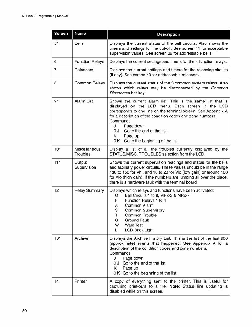
MR-2900 Programming Manual
5* Bells Displays the current status of the bell circuits. Also shows thetimers and settings for the cut-off. See screen 11 for acceptablesupervision values. See screen 39 for addressable bells.
6 Function Relays Displays the current settings and timers for the 4 function relays.
7 Releasers Displays the current settings and timers for the releasing circuits(if any). See screen 40 for addressable releasers.
8 Common Relays Displays the current status of the 3 common system relays. Alsoshows which relays may be disconnected by the CommonDisconnect hot-key.
9* Alarm List Shows the current alarm list. This is the same list that isdisplayed on the LCD menu. Each screen in the LCDcorresponds to one line on the terminal screen. See Appendix Afor a description of the condition codes and zone numbers.Commands
J Page down0 J Go to the end of the listK Page up0 K Go to the beginning of the list
10* MiscellaneousTroubles
Display a list of all the troubles currently displayed by theSTATUS/MISC. TROUBLES selection from the LCD.
11* OutputSupervision
Shows the current supervision readings and status for the bellsand auxiliary power circuits. These values should be in the range130 to 150 for Vhi, and 10 to 20 for Vlo (low gain) or around 100for Vlo (high gain). If the numbers are jumping all over the place,there is a hardware fault with the terminal board.
12 Relay Summary Displays which relays and functions have been activated:O Bell Circuits 1 to 8, MRx-3 & MRx-7F Function Relays 1 to 4A Common AlarmS Common SupervisoryT Common TroubleG Ground FaultW Walk TestL LCD Back Light
13* Archive Displays the Archive History List. This is the list of the last 900(approximate) events that happened. See Appendix A for adescription of the condition codes and zone numbers.Commands
J Page down0 J Go to the end of the listK Page up0 K Go to the beginning of the list
14 Printer A copy of everything sent to the printer. This is useful forcapturing print-outs to a file. Note: Status line updating isdisabled while on this screen.
Screen Name Description
50
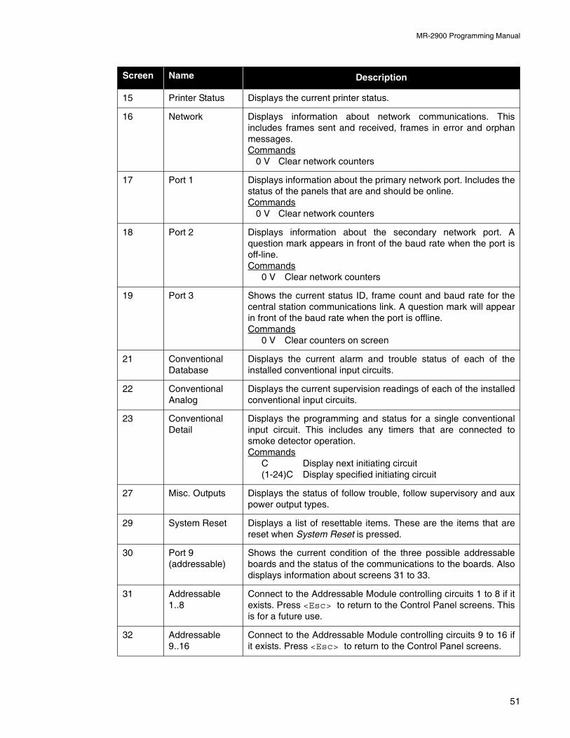
MR-2900 Programming Manual
15 Printer Status Displays the current printer status.
16 Network Displays information about network communications. Thisincludes frames sent and received, frames in error and orphanmessages.Commands
0 V Clear network counters
17 Port 1 Displays information about the primary network port. Includes thestatus of the panels that are and should be online.Commands
0 V Clear network counters
18 Port 2 Displays information about the secondary network port. Aquestion mark appears in front of the baud rate when the port isoff-line.Commands
0 V Clear network counters
19 Port 3 Shows the current status ID, frame count and baud rate for thecentral station communications link. A question mark will appearin front of the baud rate when the port is offline.Commands
0 V Clear counters on screen
21 ConventionalDatabase
Displays the current alarm and trouble status of each of theinstalled conventional input circuits.
22 ConventionalAnalog
Displays the current supervision readings of each of the installedconventional input circuits.
23 ConventionalDetail
Displays the programming and status for a single conventionalinput circuit. This includes any timers that are connected tosmoke detector operation.Commands
C Display next initiating circuit(1-24)C Display specified initiating circuit
27 Misc. Outputs Displays the status of follow trouble, follow supervisory and auxpower output types.
29 System Reset Displays a list of resettable items. These are the items that arereset when System Reset is pressed.
30 Port 9 (addressable)
Shows the current condition of the three possible addressableboards and the status of the communications to the boards. Alsodisplays information about screens 31 to 33.
31 Addressable1..8
Connect to the Addressable Module controlling circuits 1 to 8 if itexists. Press <Esc> to return to the Control Panel screens. Thisis for a future use.
32 Addressable9..16
Connect to the Addressable Module controlling circuits 9 to 16 ifit exists. Press <Esc> to return to the Control Panel screens.
Screen Name Description
51
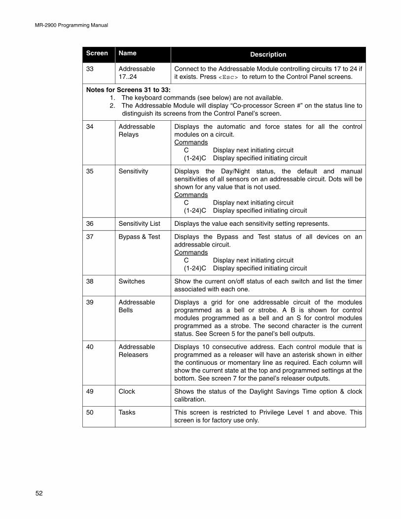
MR-2900 Programming Manual
33 Addressable17..24
Connect to the Addressable Module controlling circuits 17 to 24 ifit exists. Press <Esc> to return to the Control Panel screens.
Notes for Screens 31 to 33:1. The keyboard commands (see below) are not available.2. The Addressable Module will display “Co-processor Screen #” on the status line to
distinguish its screens from the Control Panel’s screen.
34 AddressableRelays
Displays the automatic and force states for all the controlmodules on a circuit.Commands
C Display next initiating circuit(1-24)C Display specified initiating circuit
35 Sensitivity Displays the Day/Night status, the default and manualsensitivities of all sensors on an addressable circuit. Dots will beshown for any value that is not used.Commands
C Display next initiating circuit(1-24)C Display specified initiating circuit
36 Sensitivity List Displays the value each sensitivity setting represents.
37 Bypass & Test Displays the Bypass and Test status of all devices on anaddressable circuit.Commands
C Display next initiating circuit(1-24)C Display specified initiating circuit
38 Switches Show the current on/off status of each switch and list the timerassociated with each one.
39 AddressableBells
Displays a grid for one addressable circuit of the modulesprogrammed as a bell or strobe. A B is shown for controlmodules programmed as a bell and an S for control modulesprogrammed as a strobe. The second character is the currentstatus. See Screen 5 for the panel’s bell outputs.
40 AddressableReleasers
Displays 10 consecutive address. Each control module that isprogrammed as a releaser will have an asterisk shown in eitherthe continuous or momentary line as required. Each column willshow the current state at the top and programmed settings at thebottom. See screen 7 for the panel’s releaser outputs.
49 Clock Shows the status of the Daylight Savings Time option & clockcalibration.
50 Tasks This screen is restricted to Privilege Level 1 and above. Thisscreen is for factory use only.
Screen Name Description
52
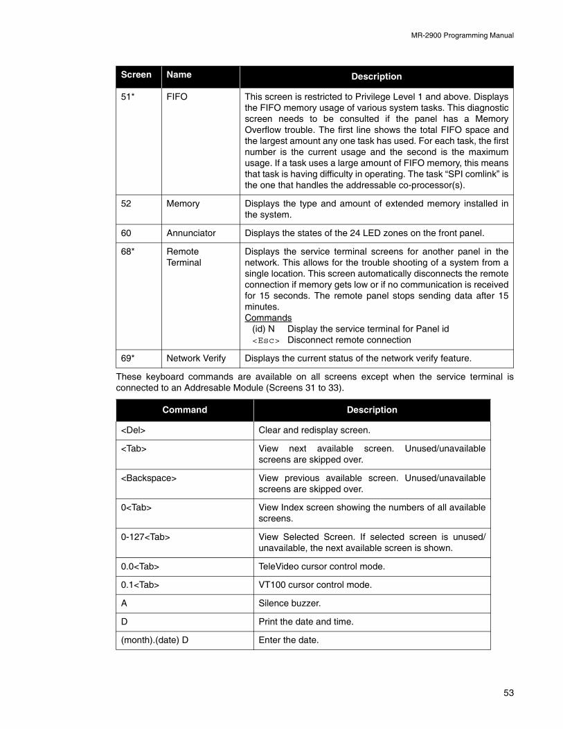
MR-2900 Programming Manual
These keyboard commands are available on all screens except when the service terminal isconnected to an Addresable Module (Screens 31 to 33).
51* FIFO This screen is restricted to Privilege Level 1 and above. Displaysthe FIFO memory usage of various system tasks. This diagnosticscreen needs to be consulted if the panel has a MemoryOverflow trouble. The first line shows the total FIFO space andthe largest amount any one task has used. For each task, the firstnumber is the current usage and the second is the maximumusage. If a task uses a large amount of FIFO memory, this meansthat task is having difficulty in operating. The task “SPI comlink” isthe one that handles the addressable co-processor(s).
52 Memory Displays the type and amount of extended memory installed inthe system.
60 Annunciator Displays the states of the 24 LED zones on the front panel.
68* RemoteTerminal
Displays the service terminal screens for another panel in thenetwork. This allows for the trouble shooting of a system from asingle location. This screen automatically disconnects the remoteconnection if memory gets low or if no communication is receivedfor 15 seconds. The remote panel stops sending data after 15minutes.Commands
(id) N Display the service terminal for Panel id<Esc> Disconnect remote connection
69* Network Verify Displays the current status of the network verify feature.
Command Description
<Del> Clear and redisplay screen.
<Tab> View next available screen. Unused/unavailablescreens are skipped over.
<Backspace> View previous available screen. Unused/unavailablescreens are skipped over.
0<Tab> View Index screen showing the numbers of all availablescreens.
0-127<Tab> View Selected Screen. If selected screen is unused/unavailable, the next available screen is shown.
0.0<Tab> TeleVideo cursor control mode.
0.1<Tab> VT100 cursor control mode.
A Silence buzzer.
D Print the date and time.
(month).(date) D Enter the date.
Screen Name Description
53
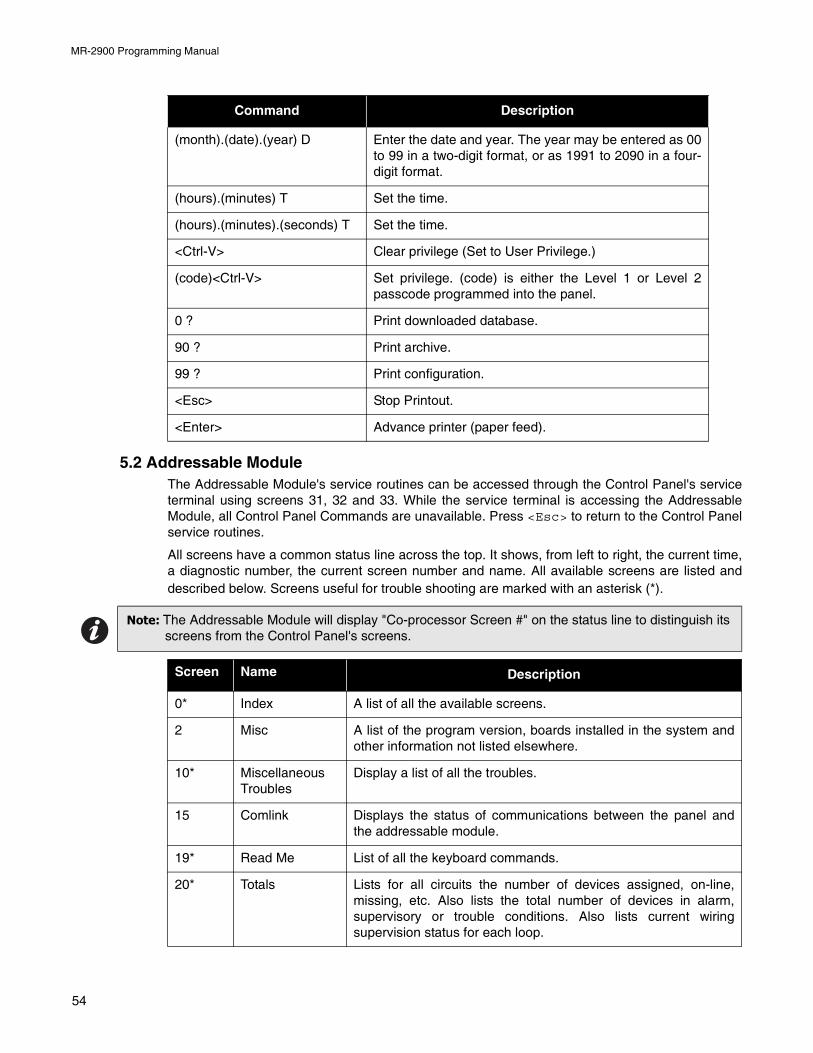
MR-2900 Programming Manual
5.2 Addressable ModuleThe Addressable Module's service routines can be accessed through the Control Panel's serviceterminal using screens 31, 32 and 33. While the service terminal is accessing the AddressableModule, all Control Panel Commands are unavailable. Press <Esc> to return to the Control Panelservice routines.
All screens have a common status line across the top. It shows, from left to right, the current time,a diagnostic number, the current screen number and name. All available screens are listed anddescribed below. Screens useful for trouble shooting are marked with an asterisk (*).
(month).(date).(year) D Enter the date and year. The year may be entered as 00to 99 in a two-digit format, or as 1991 to 2090 in a four-digit format.
(hours).(minutes) T Set the time.
(hours).(minutes).(seconds) T Set the time.
<Ctrl-V> Clear privilege (Set to User Privilege.)
(code)<Ctrl-V> Set privilege. (code) is either the Level 1 or Level 2passcode programmed into the panel.
0 ? Print downloaded database.
90 ? Print archive.
99 ? Print configuration.
<Esc> Stop Printout.
<Enter> Advance printer (paper feed).
Note: The Addressable Module will display "Co-processor Screen #" on the status line to distinguish its screens from the Control Panel's screens.
Screen Name Description
0* Index A list of all the available screens.
2 Misc A list of the program version, boards installed in the system andother information not listed elsewhere.
10* MiscellaneousTroubles
Display a list of all the troubles.
15 Comlink Displays the status of communications between the panel andthe addressable module.
19* Read Me List of all the keyboard commands.
20* Totals Lists for all circuits the number of devices assigned, on-line,missing, etc. Also lists the total number of devices in alarm,supervisory or trouble conditions. Also lists current wiringsupervision status for each loop.
Command Description
54
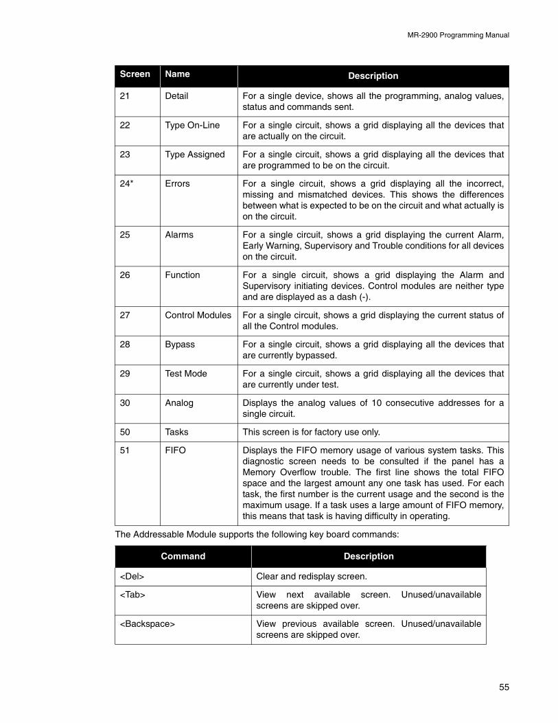
MR-2900 Programming Manual
The Addressable Module supports the following key board commands:
21 Detail For a single device, shows all the programming, analog values,status and commands sent.
22 Type On-Line For a single circuit, shows a grid displaying all the devices thatare actually on the circuit.
23 Type Assigned For a single circuit, shows a grid displaying all the devices thatare programmed to be on the circuit.
24* Errors For a single circuit, shows a grid displaying all the incorrect,missing and mismatched devices. This shows the differencesbetween what is expected to be on the circuit and what actually ison the circuit.
25 Alarms For a single circuit, shows a grid displaying the current Alarm,Early Warning, Supervisory and Trouble conditions for all deviceson the circuit.
26 Function For a single circuit, shows a grid displaying the Alarm andSupervisory initiating devices. Control modules are neither typeand are displayed as a dash (-).
27 Control Modules For a single circuit, shows a grid displaying the current status ofall the Control modules.
28 Bypass For a single circuit, shows a grid displaying all the devices thatare currently bypassed.
29 Test Mode For a single circuit, shows a grid displaying all the devices thatare currently under test.
30 Analog Displays the analog values of 10 consecutive addresses for asingle circuit.
50 Tasks This screen is for factory use only.
51 FIFO Displays the FIFO memory usage of various system tasks. Thisdiagnostic screen needs to be consulted if the panel has aMemory Overflow trouble. The first line shows the total FIFOspace and the largest amount any one task has used. For eachtask, the first number is the current usage and the second is themaximum usage. If a task uses a large amount of FIFO memory,this means that task is having difficulty in operating.
Command Description
<Del> Clear and redisplay screen.
<Tab> View next available screen. Unused/unavailablescreens are skipped over.
<Backspace> View previous available screen. Unused/unavailablescreens are skipped over.
Screen Name Description
55
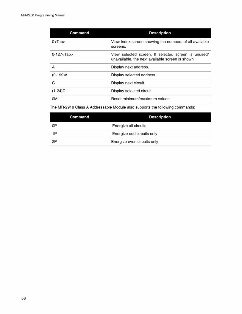
MR-2900 Programming Manual
The MR-2919 Class A Addressable Module also supports the following commands:
0<Tab> View Index screen showing the numbers of all availablescreens.
0-127<Tab> View selected screen. If selected screen is unused/unavailable, the next available screen is shown.
A Display next address.
(0-199)A Display selected address.
C Display next circuit.
(1-24)C Display selected circuit.
0M Reset minimum/maximum values.
Command Description
0P Energize all circuits
1P Energize odd circuits only
2P Energize even circuits only
Command Description
56
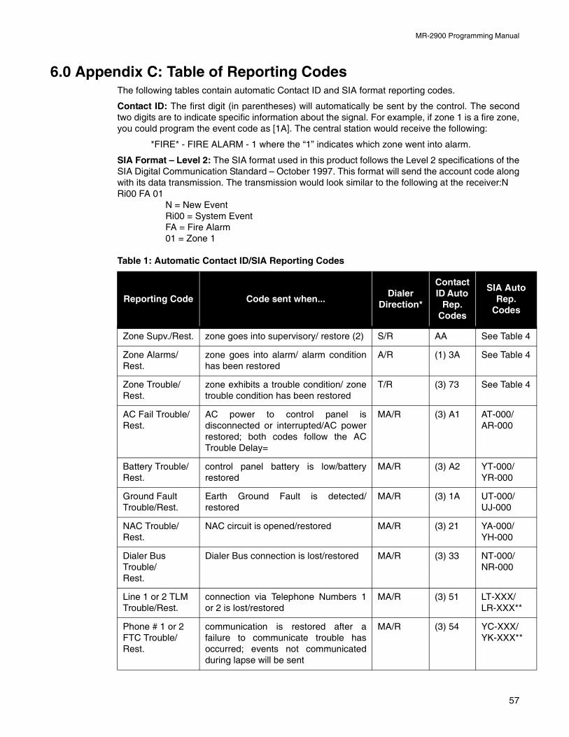
MR-2900 Programming Manual
6.0 Appendix C: Table of Reporting CodesThe following tables contain automatic Contact ID and SIA format reporting codes.
Contact ID: The first digit (in parentheses) will automatically be sent by the control. The secondtwo digits are to indicate specific information about the signal. For example, if zone 1 is a fire zone,you could program the event code as [1A]. The central station would receive the following:
*FIRE* - FIRE ALARM - 1 where the “1” indicates which zone went into alarm.
SIA Format – Level 2: The SIA format used in this product follows the Level 2 specifications of theSIA Digital Communication Standard – October 1997. This format will send the account code alongwith its data transmission. The transmission would look similar to the following at the receiver:NRi00 FA 01
N = New EventRi00 = System EventFA = Fire Alarm01 = Zone 1
Table 1: Automatic Contact ID/SIA Reporting Codes
Reporting Code Code sent when...Dialer
Direction*
Contact ID Auto
Rep. Codes
SIA Auto Rep.
Codes
Zone Supv./Rest. zone goes into supervisory/ restore (2) S/R AA See Table 4
Zone Alarms/Rest.
zone goes into alarm/ alarm conditionhas been restored
A/R (1) 3A See Table 4
Zone Trouble/Rest.
zone exhibits a trouble condition/ zonetrouble condition has been restored
T/R (3) 73 See Table 4
AC Fail Trouble/Rest.
AC power to control panel isdisconnected or interrupted/AC powerrestored; both codes follow the ACTrouble Delay=
MA/R (3) A1 AT-000/AR-000
Battery Trouble/Rest.
control panel battery is low/batteryrestored
MA/R (3) A2 YT-000/YR-000
Ground Fault Trouble/Rest.
Earth Ground Fault is detected/restored
MA/R (3) 1A UT-000/UJ-000
NAC Trouble/Rest.
NAC circuit is opened/restored MA/R (3) 21 YA-000/YH-000
Dialer Bus Trouble/Rest.
Dialer Bus connection is lost/restored MA/R (3) 33 NT-000/NR-000
Line 1 or 2 TLM Trouble/Rest.
connection via Telephone Numbers 1or 2 is lost/restored
MA/R (3) 51 LT-XXX/LR-XXX**
Phone # 1 or 2 FTC Trouble/Rest.
communication is restored after afailure to communicate trouble hasoccurred; events not communicatedduring lapse will be sent
MA/R (3) 54 YC-XXX/YK-XXX**
57
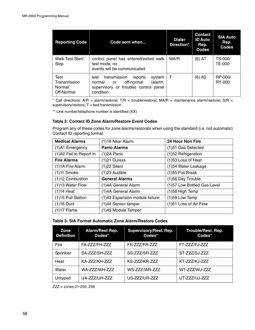
MR-2900 Programming Manual
* Call directions: A/R = alarm/restoral; T/R = trouble/restoral; MA/R = maintenance alarm/restoral; S/R =supervisory/restore; T = test transmission
** Line number/telephone number is identified (XX)
Table 2: Contact ID Zone Alarm/Restore Event Codes
Program any of these codes for zone alarms/restorals when using the standard (i.e. not automatic)Contact ID reporting format:
Table 3: SIA Format Automatic Zone Alarm/Restore Codes
ZZZ = zones 01-250, 256
Walk Test Start/Stop
control panel has entered/exited walktest mode; noevents will be communicated
MA/R (6) A7 TS-000/TE-000
Test Transmission Normal/Off-Normal
test transmission reports systemnormal or off-normal (alarm,supervisory or trouble) control panelcondition
T (6) A2 RP-000/RY-000
Medical Alarms (1)18 Near Alarm 24 Hour Non Fire
(1)A1 Emergency Panic Alarms (1)51 Gas Detected
(1)A2 Fail to Report In (1)2A Panic (1)52 Refrigeration
Fire Alarms (1)21 Duress (1)53 Loss of Heat
(1)1A Fire Alarm (1)22 Silent (1)54 Water Leakage
(1)11 Smoke (1)23 Audible (1)55 Foil Break
(1)12 Combustion General Alarms (1)56 Day Trouble
(1)13 Water Flow (1)4A General Alarm (1)57 Low Bottled Gas Level
(1)14 Heat (1)4A General Alarm (1)58 High Temp
(1)15 Pull Station (1)43 Expansion module failure (1)59 Low Temp
(1)16 Duct (1)44 Sensor tamper (1)61 Loss of Air Flow
(1)17 Flame (1)45 Module Tamper
Zone Definition
Alarm/Rest Rep. Codes*
Supervisory/Rest. Rep. Codes*
Trouble/Rest. Rep. Codes*
Fire FA-ZZZ/FH-ZZZ FS-ZZZ/FR-ZZZ FT-ZZZ/FJ-ZZZ
Sprinkler SA-ZZZ/SH-ZZZ SS-ZZZ/SR-ZZZ ST-ZZZ/SJ-ZZZ
Heat KA-ZZZ/KH-ZZZ KS-ZZZ/KR-ZZZ KT-ZZZ/KJ-ZZZ
Water WA-ZZZ/WH-ZZZ WS-ZZZ/WR-ZZZ WT-ZZZ/WJ-ZZZ
Untyped UA-ZZZ/UH-ZZZ US-ZZZ/UR-ZZZ UT-ZZZ/UJ-ZZZ
Reporting Code Code sent when...Dialer
Direction*
Contact ID Auto
Rep. Codes
SIA Auto Rep.
Codes
58


© 2009 Secutron, Inc.
Canada 25 Interchange Way Vaughan, ON L4K 5W3 Tel: (888) SECUTRON (888) 732-8876 Fax: (905) 660-4113
U.S.A4575 Witmer Industrial EstatesNiagara Falls, New York 14305Tel: (888) SECUTRON (888) 732-8876Fax: (905) 660-4113
No part of this publication may be reproduced, transmitted, transcribed, stored in a retrieval system, or translated into any language or computer language, in any form by any means electronic, magnetic, optical, chemical, manual, or otherwise without the prior consent of Secutron.