Embed Size (px)
Citation preview

APPENDIX G PH NEUTRALIZATION SYSTEM TECHNICAL MEMORANDUM

BCM Construction
21201 Itasca Street Chatsworth, CA 91311 USA Phone: +1.818.998.3500 Fax: +1.818.998.4939 Web: www.wastech.com
Project No.: 151-205
ProDELTA Plus Continuous pH Neutralization System
PDP-200-2-SC-G-B-T-AX-4-N4-LR-OCV
Process & Equipment Description 9/4/2015
Submitted for Approval

Wastech Controls & Engineering, Inc Process & Equipment Description Project No. 151‐205
Submitted for Approval – 9/4/2015 Page 2 of 11
1. Process Description ...................................................................................................................... 3
1.1. Sump Tank (T-SUMP) ............................................................................................................................ 3 1.2. ProDELTA-Plus 200-GPM pH Adjustment System ................................................................................ 3
2. Equipment Description (Sump) .................................................................................................... 3 2.1. Transfer Pumps (P1-SUMP, P2-SUMP) ................................................................................................. 3 2.2. Mixer (M-SUMP) ..................................................................................................................................... 3 2.3. Level Transmitter (LT-SUMP) ................................................................................................................ 4 2.4. High-High Level Switch (LSHH-SUMP) .................................................................................................. 4 2.5. Low-Low Level Switch (LSLL-SUMP) ..................................................................................................... 4
3. Equipment Description (pH Adjustment System) ....................................................................... 4 3.1. Reaction Tanks (RT-1, RT-2) ................................................................................................................. 4 3.2. Mixers (M-RT1, M-RT2) ......................................................................................................................... 4 3.3. pH Probes (AE1-RT1, AE2-RT1, AE1-RT2, AE2-RT2) .......................................................................... 5 3.4. Control Valves (AFV1-MPS, AFV2-MPS) ............................................................................................... 5 3.5. Discharge pH Probes (AE1-MPS, AE2-MPS) ........................................................................................ 5 3.6. Air Compressor (CDA-1) ........................................................................................................................ 6 3.7. Pressure Switch (PS-1) .......................................................................................................................... 6 3.8. High-High Level Switch (LSHH-RT1) ..................................................................................................... 6 3.9. Flowmeter (FE/FT-MPS) ........................................................................................................................ 6
4. Chemical Delivery System ............................................................................................................ 6 4.1. Caustic Supply Tank (CT-1) ................................................................................................................... 6 4.2. Caustic Heating Equipment .................................................................................................................... 6 4.3. Caustic Metering Pumps (CP-1, CP-2) ................................................................................................... 6 4.4. Caustic Tank Level Transmitter (LT-CT1) .............................................................................................. 7 4.5. Caustic Tank High-High Level Switch (LSHH-CT1) ................................................................................ 7 4.6. Caustic Fill Pump (P1-CAUSTIC) ........................................................................................................... 7 4.7. Caustic Fill Tank Low Level (LSL-CAUSTIC) ......................................................................................... 7 4.8. Leak Detection Switch (LD-CT1) ............................................................................................................ 7 4.9. Temperature Sensor (TE1/TT1-CT1) ..................................................................................................... 7 4.10. Temperature Sensor (TE2/TT2-CT1) ..................................................................................................... 7 4.11. Acid Supply Tank (AT-1) ........................................................................................................................ 8 4.12. Acid Metering Pumps (AP-1, AP-2) ........................................................................................................ 8 4.13. Acid Tank Level Transmitter (LT-AT1) ................................................................................................... 8 4.14. Acid Tank High-High Level Switch (LSHH-AT1) ..................................................................................... 8 4.15. Acid Fill Pump (P1-ACID) ....................................................................................................................... 8 4.16. Acid Fill Tank Low Level (LSL-ACID) ..................................................................................................... 8 4.17. Leak Detection Switch (LD-AT1) ............................................................................................................ 8
5. Control System ............................................................................................................................... 8 5.1. Process Control ...................................................................................................................................... 8 5.2. Process Monitoring ................................................................................................................................. 9 5.3. Manual Controls ................................................................................................................................... 10 5.4. Digital Data Logger ............................................................................................................................... 10 5.5. Alarm Description ................................................................................................................................. 10 5.6. Silence Button ...................................................................................................................................... 11 5.7. Process Switch ..................................................................................................................................... 11 5.8. Emergency Stop ................................................................................................................................... 11 5.9. Communication with Facility Management System .............................................................................. 11

Wastech Controls & Engineering, Inc Process & Equipment Description Project No. 151‐205
Submitted for Approval – 9/4/2015 Page 3 of 11
1. PROCESS DESCRIPTION
1.1. Sump Tank (T-SUMP)
1.1.1. Industrial wastewater enters the Sump Tank (T-SUMP). The submersible mixer (M-SUMP) continuously stirs the Sump contents to create a homogenous mixture. Transfer Pumps P1-SUMP and P2-SUMP pump the wastewater from the Sump to the ProDELTA-Plus pH Adjustment System based on tank level and operational status of the downstream equipment.
1.2. ProDELTA-Plus 200-GPM pH Adjustment System
1.2.1. Industrial wastewater enters the first Reaction Tank (RT-1) from which the wastewater gravity flows to the second Reaction Tank (RT-2). Each Reaction Tank is equipped with a mixer (agitator) that continuously stirs the wastewater to maintain a homogenous environment within each Reaction Tank. Two (2) pH Probes are installed in each Reaction Tank. The PLC-based control system automatically adjusts the pH within the Reaction Tanks using acid and/or caustic based on the pH readings from the pH Probes. After the wastewater is neutralized in the Reaction Tanks it gravity flows to the Monitoring Pipe Spool (MPS). If the pH in the Monitoring Pipe Spool is within dischargeable limits the wastewater is discharged to the sewer. If the pH is out of range, the wastewater is returned to the Sump for additional treatment.
2. EQUIPMENT DESCRIPTION (SUMP)
2.1. Transfer Pumps (P1-SUMP, P2-SUMP)
2.1.1. Transfer Pumps P1-SUMP and P2-SUMP are submersible pumps that transfer wastewater from the Sump to the ProDELTA-Plus pH Adjustment System. The pumps operate in an alternating lead/lag operation.
2.1.2. Transfer Pumps P1-SUMP and P2-SUMP are each rated for 200 GPM @ 35’ TDH. The transfer pumps operate using VFDs (VFD-1, VFD-2) which regulate the speed of the motor to maintain a user-adjustable speed based on the liquid level in the sump.
2.1.3. The PLC-Based Control System automatically alternates between the two transfer pumps (P1-SUMP or P2-SUMP) as the lead pump for each pumping cycle. The Control System will automatically start and stop the lead pump based on the liquid level in the Sump Tank (T-SUMP) measured by the Level Transmitter (LT-SUMP), whenever the Hand-Off-Auto (HOA) switch for each pump is set to AUTO. The operator may also select the lead pump manually.
2.1.4. When the pump HOA switch is set to HAND, the pump will operate regardless of the level measured in the tank. If the pump is left ON, it may run dry, causing damage to the pump.
2.2. Mixer (M-SUMP)
2.2.1. Mixer (M-SUMP) is used to continuously stir the wastewater to maintain a homogenous environment within the Sump Tank. The mixer operates automatically when the Process Switch is ON.
Wastech Controls & Engineering, Inc Process & Equipment Description Project No. 151‐205
Submitted for Approval – 9/4/2015 Page 4 of 11
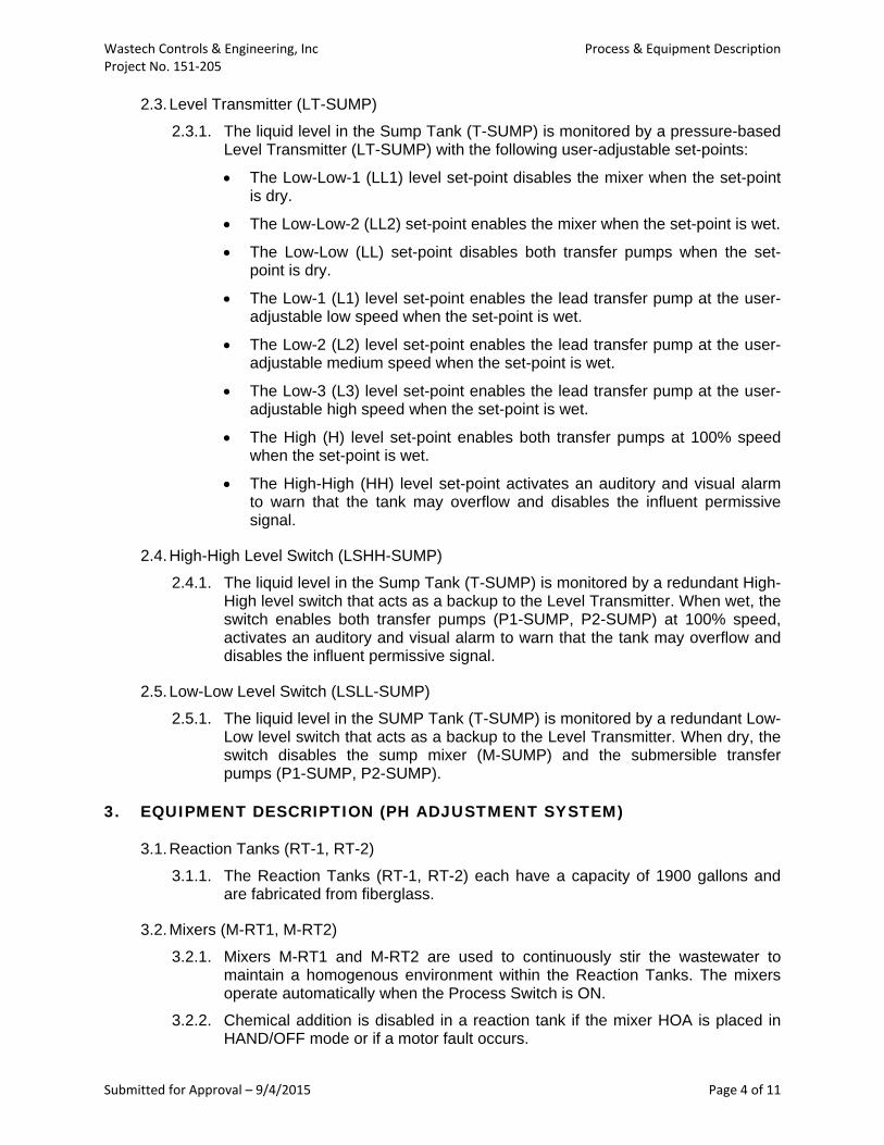
2.3. Level Transmitter (LT-SUMP)
2.3.1. The liquid level in the Sump Tank (T-SUMP) is monitored by a pressure-based Level Transmitter (LT-SUMP) with the following user-adjustable set-points:
The Low-Low-1 (LL1) level set-point disables the mixer when the set-point is dry.
The Low-Low-2 (LL2) set-point enables the mixer when the set-point is wet.
The Low-Low (LL) set-point disables both transfer pumps when the set-point is dry.
The Low-1 (L1) level set-point enables the lead transfer pump at the user-adjustable low speed when the set-point is wet.
The Low-2 (L2) level set-point enables the lead transfer pump at the user-adjustable medium speed when the set-point is wet.
The Low-3 (L3) level set-point enables the lead transfer pump at the user-adjustable high speed when the set-point is wet.
The High (H) level set-point enables both transfer pumps at 100% speed when the set-point is wet.
The High-High (HH) level set-point activates an auditory and visual alarm to warn that the tank may overflow and disables the influent permissive signal.
2.4. High-High Level Switch (LSHH-SUMP)
2.4.1. The liquid level in the Sump Tank (T-SUMP) is monitored by a redundant High-High level switch that acts as a backup to the Level Transmitter. When wet, the switch enables both transfer pumps (P1-SUMP, P2-SUMP) at 100% speed, activates an auditory and visual alarm to warn that the tank may overflow and disables the influent permissive signal.
2.5. Low-Low Level Switch (LSLL-SUMP)
2.5.1. The liquid level in the SUMP Tank (T-SUMP) is monitored by a redundant Low-Low level switch that acts as a backup to the Level Transmitter. When dry, the switch disables the sump mixer (M-SUMP) and the submersible transfer pumps (P1-SUMP, P2-SUMP).
3. EQUIPMENT DESCRIPTION (PH ADJUSTMENT SYSTEM)
3.1. Reaction Tanks (RT-1, RT-2)
3.1.1. The Reaction Tanks (RT-1, RT-2) each have a capacity of 1900 gallons and are fabricated from fiberglass.
3.2. Mixers (M-RT1, M-RT2)
3.2.1. Mixers M-RT1 and M-RT2 are used to continuously stir the wastewater to maintain a homogenous environment within the Reaction Tanks. The mixers operate automatically when the Process Switch is ON.
3.2.2. Chemical addition is disabled in a reaction tank if the mixer HOA is placed in HAND/OFF mode or if a motor fault occurs.

Wastech Controls & Engineering, Inc Process & Equipment Description Project No. 151‐205
Submitted for Approval – 9/4/2015 Page 5 of 11
3.3. pH Probes (AE1-RT1, AE2-RT1, AE1-RT2, AE2-RT2)
3.3.1. pH Probes AE1-RT1, AE2-RT1, AE1-RT2 and AE2-RT2 measure the pH of the solution in the Reaction Tanks (RT-1, RT-2). Transmitters AT-1, AT-2, AT-3, and AT-4 receive signals from the pH Probes.
3.3.2. The PLC-based control system starts and stops the chemical metering pumps as needed to adjust the measured pH in each Reaction Tank. The Control System adjusts the rate of delivery of the chemical metering pumps, depending on the deviation from the target set-point (i.e. the metering pump operates at a reduced delivery rate for a small deviation and at an increased delivery rate for a large deviation). Chemical addition is disabled in a Reaction Tank in case of a pH transmitter or mixer fault.
3.3.3. The pH control set-points are user-adjustable for each Reaction Tank. The system will adjust the gains of the pH loops based on the flow rate through the system. The factory settings are noted below. These may be changed after system commissioning to adjust to actual operating conditions.
3.3.4. Reaction Tank RT-1 settings:
CP-1 operates when pH < 6.25
AP-1 operates when pH > 8.75
3.3.5. Reaction Tank RT-2 settings:
CP-2 operates when pH < 6.25
AP-2 operates when pH > 8.75
3.3.6. In each reaction tank, one pH Probe will be online (user-defined) and control pH adjustment and alarms. The other will be on stand-by and serve as a deviation monitor for the online pH Probe. If the pH measurements from the two probes drift apart by a user-defined value an alarm will be activated. If the measurements drift apart beyond a second user-adjustable value, chemical addition to the corresponding Reaction Tank will be disabled. In the event that the online pH Probe experiences a fault condition, the stand-by pH Probe will automatically assume online status.
3.4. Control Valves (AFV1-MPS, AFV2-MPS)
3.4.1. Control Valves AFV1-MPS and AFV2-MPS are pneumatically actuated two-way valves that direct the flow of wastewater to the sewer and to the Sump for additional treatment. When the pH of the wastewater inside the Monitoring Pipe Spool (MPS) is within dischargeable limits the valves are energized and open to the sewer. When the pH of the wastewater is outside dischargeable limits, the valves are then de-energized and open to the Sump for additional treatment.
3.5. Discharge pH Probes (AE1-MPS, AE2-MPS)
3.5.1. pH Probes AE1-MPS and AE2-MPS measure the pH of the wastewater in the monitoring pipe spool installed on the discharge piping of the system. Transmitters AT-5 and AT-6 receive signals from the pH probes.
3.5.2. In the monitoring pipe spool, one pH Probe will be online (user-defined) and control pH related alarms and system responses. The other will be on stand-by and serve as a deviation monitor for the online pH Probe. If the pH

Wastech Controls & Engineering, Inc Process & Equipment Description Project No. 151‐205
Submitted for Approval – 9/4/2015 Page 6 of 11
measurements from the two probes drift apart by a user-defined value an alarm will be activated. If the measurements drift apart beyond a second user-adjustable value the system will disable discharge to the sewer. In the event that the online pH Probe experiences a fault condition, the stand-by pH Probe will automatically assume online status.
3.6. Air Compressor (CDA-1)
3.6.1. Air Compressor CDA-1 supplies clean dry air to Pumps P1-CAUSTIC and P1-ACID and pneumatic control valves AFV1-MPS and AFV2-MPS.
3.7. Pressure Switch (PS-1)
3.7.1. A Pressure Switch (PS-1) is installed on the CDA supply line to confirm CDA pressure is available to the system. If low pressure is detected by the Pressure Switch an auditory and visual alarm is activated.
3.8. High-High Level Switch (LSHH-RT1)
3.8.1. The liquid level in the first Reaction Tank (RT-1) is monitored by a single-point level switch. When wet, the switch activates an auditory and visual alarm to warn that the tank may overflow and disables the Sump Transfer Pumps.
3.9. Flowmeter (FE/FT-MPS)
3.9.1. Flowmeter FE-MPS is a magnetic flowmeter that measures the flow rate of wastewater discharged from the system. The system uses the position switch feedback from the control valves on the discharge to monitor whether the system effluent is discharged to the sewer or recirculated to the sump for additional treatment. Both the total flow to the sump and the total flow to the sewer are data-logged via the HMI’s integral Data Logger.
4. CHEMICAL DELIVERY SYSTEM
4.1. Caustic Supply Tank (CT-1)
4.1.1. Caustic Supply Tank CT-1 has a capacity of 150 gallons and is a fabricated triple-welded polypropylene tank.
4.1.2. Tank CT-1 is double contained.
4.2. Caustic Heating Equipment
4.2.1. Caustic Cabinet Heater H1-CT1 is a blanket heater installed in the Caustic Metering Pump cabinet to prevent the caustic in the metering pumps from freezing. The heating set-point is user-adjustable
4.2.2. Caustic Tank Heater H2-CT1 is a submersible heater that is installed to prevent the caustic from freezing. The heating set-point is user-adjustable.
4.2.3. Caustic Heat Trace Cable H3-CT1 is installed on the caustic injection tubing double containment piping to prevent the caustic in the injection lines from freezing. The heating set-point is user-adjustable.
4.3. Caustic Metering Pumps (CP-1, CP-2)
4.3.1. The Caustic Metering Pumps deliver caustic to the Reaction Tanks according to the control set-points described in Section 3.

Wastech Controls & Engineering, Inc Process & Equipment Description Project No. 151‐205
Submitted for Approval – 9/4/2015 Page 7 of 11
4.3.2. The Caustic Metering Pumps are each rated for 20 GPH @ 30 PSI.
4.4. Caustic Tank Level Transmitter (LT-CT1)
4.4.1. A level transmitter (LT-CT1) is installed in the Caustic Supply Tank with the following user-adjustable set-points:
The Low (L) level set-point activates an auditory and visual alarm to warn that the caustic level is low.
The High (H) level set-point disables the Caustic Fill Pump when the set-point is wet.
The High-High (HH) level set-point activates an auditory and visual alarm to warn that the tank may overflow.
4.5. Caustic Tank High-High Level Switch (LSHH-CT1)
4.5.1. An ultrasonic level switch (LSHH-CT1) is installed in the Caustic Supply Tank to monitor the Caustic Tank level during filling. If High-High level is detected, the system will stop filling the Caustic Supply Tank and activate an auditory and visual alarm to warn that the tank may overflow.
4.6. Caustic Fill Pump (P1-CAUSTIC)
4.6.1. The Caustic Fill Pump is an air operated diaphragm pump that delivers caustic to the Caustic Supply Tank CT-1.
4.6.2. The Caustic Fill Pump is rated for 8 GPM @ 90’ TDH.
4.7. Caustic Fill Tank Low Level (LSL-CAUSTIC)
4.7.1. An ultrasonic level switch (LSL-CAUSTIC) is installed in the Caustic Fill Tank to warn when the caustic level is low. If Low level is detected, the Caustic Fill Pump (P1-CAUSTIC) will be disabled and an auditory and visual alarm will be activated.
4.8. Leak Detection Switch (LD-CT1)
4.8.1. A leak detection switch is installed in the secondary containment of the Caustic Supply Tank to monitor the presence of liquid resulting from primary tank failure or overflow.
4.9. Temperature Sensor (TE1/TT1-CT1)
4.9.1. Temperature sensor TE1/TT1-CT1 is installed inside the caustic supply tank to monitor the temperature of the caustic solution. If the temperature of the caustic solution drops below the user-adjustable temperature setting the submersible heater will be enabled.
4.10. Temperature Sensor (TE2/TT2-CT1)
4.10.1. Temperature sensor TE2/TT2-CT1 is installed on the caustic supply line to monitor the ambient temperature around the caustic supply line. If the temperature of the supply line drops below the user-adjustable temperature setting the heat trace cable will be enabled.

Wastech Controls & Engineering, Inc Process & Equipment Description Project No. 151‐205
Submitted for Approval – 9/4/2015 Page 8 of 11
4.11. Acid Supply Tank (AT-1)
4.11.1. Acid supply tank AT-1 has a capacity of 150 gallons and is fabricated triple-welded polypropylene tank.
4.11.2. Tank AT-1 is double contained.
4.12. Acid Metering Pumps (AP-1, AP-2)
4.12.1. The Acid Metering Pumps deliver acid to the Reaction Tanks according to the control set-points described in Section 3.
4.12.2. The Acid Metering Pumps are each rated for 20 GPH @ 30 PSI.
4.13. Acid Tank Level Transmitter (LT-AT1)
4.13.1. A level transmitter (LT-AT1) is installed in the Acid Supply Tank with the following user-adjustable set-points:
The Low (L) level set-point activates an auditory and visual alarm to warn that the acid level is low.
The High (H) level set-point disables the Acid Fill Pump when the set-point is wet.
The High-High (HH) level set-point activates an auditory and visual alarm to warn that the tank may overflow.
4.14. Acid Tank High-High Level Switch (LSHH-AT1)
4.14.1. An ultrasonic level switch (LSHH-AT1) is installed in the Acid Supply Tank to monitor the Acid Tank level during filling. If High-High level is detected, the system will stop filling the Acid Supply Tank and activate an auditory and visual alarm to warn that the tank may overflow.
4.15. Acid Fill Pump (P1-ACID)
4.15.1. The Acid Fill Pump is an air operated diaphragm pump that delivers Acid to the Acid Supply Tank AT-1.
4.15.2. The Acid Fill Pump is rated for 8 GPM @ 90’ TDH.
4.16. Acid Fill Tank Low Level (LSL-ACID)
4.16.1. An ultrasonic level switch (LSL-ACID) is installed in the Acid Fill Tank to warn when the Acid level is low. If Low level is detected, the Acid Fill Pump (P1-ACID) will be disabled and an auditory and visual alarm will be activated.
4.17. Leak Detection Switch (LD-AT1)
4.17.1. A leak detection switch is installed in the secondary containment of the Acid Supply Tank to monitor the presence of liquid resulting from primary tank failure or overflow.
5. CONTROL SYSTEM
5.1. Process Control
5.1.1. The control panel contains a PLC-based Control System that provides operation of the equipment listed below:

Wastech Controls & Engineering, Inc Process & Equipment Description Project No. 151‐205
Submitted for Approval – 9/4/2015 Page 9 of 11
Caustic Fill Pump (P1-CAUSTIC)
Acid Fill Pump (P1-ACID)
Caustic Metering Pumps (CP-1, CP-2)
Acid Metering Pumps (AP-1, AP-2)
Discharge Control Valves (ABV1-MPS, ABV2-MPS)
Caustic Heaters (H1-CT1, H2-CT1, H3-CT1)
Tank Mixers (M-RT1, M-RT2)
Sump Mixer (M-SUMP)
Sump Transfer Pumps (P1-SUMP, P2-SUMP)
5.2. Process Monitoring
5.2.1. The PLC-based Control System monitors the operating parameters and equipment status listed below:
Status of the Reaction Tank Mixers (Hand/Off/Auto and On/Off for M-RT1, M-RT2)
Status of the Reaction Tank High-High Level Switch (Wet/Dry status of LSHH-RT1)
pH measured in the Reaction Tanks (AE1-RT1, AE2-RT1, AE1-RT2, AE2-RT2)
pH measured in the discharge pipe spool (AE1-MPS. AE2-MPS)
Flow measured in the discharge pipe spool (FE-MPS)
Status of the Caustic Metering Pumps (Hand/Off/Auto, On/Off, and %Output for CP-1, CP-2)
Status of the Acid Metering Pumps (Hand/Off/Auto, On/Off, and %Output for AP-1, AP-2)
Status of the Discharge Control Valves (AFV1-MPS, AFV2-MPS)
Level indication for the Caustic Storage Tank (Wet/Dry status of LSHH-CT1, % level for LT-CT1)
Level indication for the Caustic Fill Tank (Wet/Dry status of LSL-CAUSTIC) Temperature measured in caustic tank (TE1-CT1) Ambient temperature measured at caustic supply line (TE2-CT1) Status of Caustic Metering Pump Cabinet Blanket Heater (On/Off
for HT1-CT1) Status of Caustic Tank Submersible Heater (On/Off and % Output
for HT2-CT1) Status of Caustic Supply Line Heat Trace Cable (On/Off for HT3-
CT1)
Level indication for the Acid Storage Tank (Wet/Dry status of LSHH-AT1, % level for LT-AT1)
Level indication for the Acid Fill Tank (Wet/Dry status of LSL-ACID)

Wastech Controls & Engineering, Inc Process & Equipment Description Project No. 151‐205
Submitted for Approval – 9/4/2015 Page 10 of 11
Status of the Caustic Leak Detection Switch (Wet/Dry status of LD-CT1)
Status of the Acid Leak Detection Switch (Wet/Dry status of LD-AT1)
Status of system air pressure (Ok/Not Ok status of PS-1)
Level indication for the Sump (% level for LT-SUMP and Wet/Dry status of operational set-points, Wet/Dry status of LSLL-SUMP, LSHH-SUMP)
Status of the Sump Transfer Pumps (Hand/Off/Auto and On/Off for P1-SUMP, P2-SUMP)
Status of the Sump Mixer (Hand/Off/Auto and On/Off for M-SUMP)
5.3. Manual Controls
5.3.1. Manual controls are provided for the system equipment to allow for equipment maintenance, control loop tuning and troubleshooting. Under normal operations, all controls are to be set to AUTO. The following manual controls are provided:
Process On/Off switch to place the Control System in AUTO
Hand/Off to start and stop the Reaction Tank Mixers (M-RT1, M-RT2)
Hand/Off to start and stop the Sump Mixer (M-SUMP)
Hand/Off to start and stop the Sump Transfer Pumps (P1-SUMP, P2-SUMP)
Hand/Off to start and stop the Caustic Fill Pump (P1-CAUSTIC)
Hand/Off to start and stop the Acid Fill Pump (P1-ACID)
Hand/Off to start and stop the Caustic Metering Pumps (CP-1, CP-2)
Hand/Off to start and stop the Acid Metering Pumps (AP-1, AP-2)
Auto/Off to start and stop the Caustic Tank Heater (H1-CT1)
Auto/Off to start and stop the Caustic Cabinet Blanket Heater (H2-CT1)
Auto/Off to start and stop the Caustic Heat Trace Cable (H3-CT1)
Open/Close of the Discharge Control Valves (AFV1-MPS, AFV2-MPS)
Hand/Off to start and stop the Air Compressor (CDA-1)
5.4. Digital Data Logger 5.4.1. The HMI integral data logger records the following:
pH within the discharge piping measured by pH Sensor AE1-MPS or AE2-MPS
Flow Rate to the sewer measured by Flowmeter FE-MPS
Total Flow to the sewer measured by Flowmeter FE-MPS
5.5. Alarm Description
5.5.1. Refer to the System Response and Interlock Matrix for audible alarm annunciator and visual alarm beacon activation at the Control Panel.
Wastech Controls & Engineering, Inc Process & Equipment Description Project No. 151‐205
Submitted for Approval – 9/4/2015 Page 11 of 11
5.6. Silence Button
5.6.1. There is a SILENCE button on the Control Panel that will turn off the audible alarm annunciator. Pressing this button will not reset the alarm condition that initiated the alarm. Alarms are reset automatically or manually, depending on the specific type of alarm.
5.7. Process Switch
5.7.1. The Control Panel is equipped with a Process On/Off switch to place the Control System in AUTO. When the switch is placed in the Off position all automated functions of the system will be disabled. Power to the instrumentation will remain energized and they will continue to function. Certain alarms are suppressed when the Process Switch is in the Off position (refer to the System Response and Interlock Matrix for more details).
5.8. Emergency Stop
5.8.1. The Control Panel is equipped with an emergency stop button (E-STOP). In the event of system emergency, pressing this mushroom-style button will de-energize all power or devices with potential energy (e.g. those controlled with compressed dry air). Power to the instrumentation will remain energized and they will continue to function. Treatment of wastewater will be disabled when the E-STOP button is pressed. To reset the E-STOP button, pull on it to the full-out position.
5.9. Communication with Facility Management System
5.9.1. The Control Panel is equipped with the dry contacts, inputs, and communications listed below. Refer to the System Response and Interlock Matrix for more details.
One (1) Common Alarm Dry Contact: Energized when no alarms are present. De-energized in case of an alarm.
One (1) Influent Permissive Dry Contact: De-energized when the Process Switch is off, the E-Stop is pushed in, or the Run Permissive is not enabled. Energized under normal operating conditions.
One (1) pH Out of Range Dry Contact: De-energized when pH in the discharge pipe spool (AE1-MPS or AE2-MPS) is out of range.
One (1) Run Permissive Input: Facility is required to close contact to enable treatment system.
Two (2) Analog Flow Inputs
One (1) Communication Connection via Ethernet I/P
END OF PROCESS & EQUIPMENT DESCRIPTION

PLAN VIEW
FRONT ELEVATION VIEWSIDE ELEVATION VIEW
REAR ELEVATION VIEW
21201 Itasca Street, Chatsworth, California 91311-4922Tel: (818) 998-3500 Fax: (818) 998-4939
ANY COPYING, REPRODUCTION OR UNAUTHORIZED USE
REVISION
2014 WASTECH CONTROLS & ENGINEERING, INC.THIS DRAWING AND ALL INFORMATION HEREON IS THEPROPERTY OF WASTECH CONTROLS & ENGINEERING INC.
ENGINEERING MANAGER:
WITHOUT WRITTEN CONSENT IS PROHIBITED.
C
PROPRIETARY INFORMATION
DATEAPPROVALS
DRAWN BY:
PROJECT ENG.:
SIZEB
TITLE:
DWG. NO.
SCALE: NTS
WASTECH CONTROLS & ENGINEERING, INC.PLEASE RETURN DRAWING TO
BY
BY
PLEASE REVIEW, SIGN & RETURN ONE (1) COPY
WASTECH CONTROLS & ENGINEERING, INC.
SUBMITTED FOR APPROVAL
REVISE AS NOTED AND RESUBMIT
APPROVED AS IS APPROVED AS NOTED
SIGNATURE DATE
DATESIGNATURE
REV. DATE: BY: DESCRIPTION 1 09/17/2015 MF SUBMITTED FOR APPROVAL0 09/03/2015 MF DRAFT
BMC CONSTRUCTIONPDP 200 GPM NEUTRALIZATION SYSTEMLAYOUT
1
SHEET: 1 OF 1
151205-MG-001
NOTES:1. MATERIALS OF CONSTRUCTION: A) CHEMICAL TANKS TO BE FABRICATED FROM 3/4" THICK WHITE POLYPROPYLENE. B) ALL OTHER TANKS TO BE FRP. C) SKID TO BE ASTM A36/A500 STEEL EPOXY-COATED BLUE. D) ALL PIPING AND FITTINGS TO BE CPVC SCH 80. E) PNEUMATIC TUBING TO BE STAINLESS STEEL. F) HARDWARE TO BE 18-8 SS. G) ELECTRICAL CONDUIT TO BE PVC.2. ALL SURFACES TO BE SEALED WITH EPDM GASKET. 3. SOME SUPPORTS NOT SHOWN FOR CLARITY. ANCHOR BOLTS TO BE SPECIFIED AND SUPPLIED BY OTHERS. 4. INSTALLATION, INTERCONNECTING PIPING AND WIRING SUPPLIED AND INSTALLED BY OTHERS. INSTALLER TO PROVIDE ADEQUATE VENTILATION TO THE TANKS. 5. APPROXIMATE EQUIPMENT WEIGHTS: i) SKID DRY WEIGHT: 10200 LBS ii) SKID OPERATING WEIGHT: 45700 LBS iii) SKID MAXIMUM WEIGHT: 50200 LBS iv) MIXER MOTOR W/ GEARBOX: 180 LBS EACH
MF
JH
SS
08/24/2015
168 in
371 in
300 in
300 in
147 in
52 in
103 1/2 in
42 in
30 in
RECOMMENED CLEARANCE FORMAINTENANCE AND CALIBRATION
REQUIRED CLEARANCE FORHIGH VOLTAGE ELECTRICAL EQUIPMENT
RT-2
RT-1
CT-1
AT-1
ELECTRICAL PANEL
101 in
WASTEWATERINLET
6" FLANGE
DISCHARGE TOSEWER
6" FLANGE
OUT OFCOMPLIANCE
TO SUMP6" FLANGE
WASTEWATERINLET
6" FLANGE
48 3/4 in
34 1/4 in
DISCHARGE TOSEWER6" FLANGE
87 1/4 in
96 in
118 inMAXIMUMSHIPPINGHEIGHT
OUT OFCOMPLIANCETO SUMP6" FLANGE
158 1/4 in
314 1/2 in
92 1/2 in
185 in
HEADROOM REQUIRED FORREMOVING MIXER MOTOR

FRONT ISOMETRIC VIEW
REAR ISOMETRIC VIEW
21201 Itasca Street, Chatsworth, California 91311-4922Tel: (818) 998-3500 Fax: (818) 998-4939
ANY COPYING, REPRODUCTION OR UNAUTHORIZED USE
REVISION
2014 WASTECH CONTROLS & ENGINEERING, INC.THIS DRAWING AND ALL INFORMATION HEREON IS THEPROPERTY OF WASTECH CONTROLS & ENGINEERING INC.
ENGINEERING MANAGER:
WITHOUT WRITTEN CONSENT IS PROHIBITED.
C
PROPRIETARY INFORMATION
DATEAPPROVALS
DRAWN BY:
PROJECT ENG.:
SIZEB
TITLE:
DWG. NO.
SCALE: NTS
WASTECH CONTROLS & ENGINEERING, INC.PLEASE RETURN DRAWING TO
BY
BY
PLEASE REVIEW, SIGN & RETURN ONE (1) COPY
WASTECH CONTROLS & ENGINEERING, INC.
SUBMITTED FOR APPROVAL
REVISE AS NOTED AND RESUBMIT
APPROVED AS IS APPROVED AS NOTED
SIGNATURE DATE
DATESIGNATURE
NOZZLE SCHEDULE
NOZZLE DESCRIPTION QTY SERVICEN1 1/2" FNPT 2 CHEMICAL INLETN2 2" FNPT 2 DOUBLE CONTAINMENTN3 2" FNPT 2 VENTN4 2" FNPT 2 VENTN5 1" FNPT 2 DRAINN6 3/8" FNPT 1 CDA TO P1-CAUSTICN7 3/8" FNPT 1 CDA TO P1-ACIDN8 6" FLANGE 1 WASTEWATER INLETN9 6" FLANGE 1 EFFLUENT TO SEWERN10 6" FLANGE 1 OUT-OF-SPEC RETURNN11 8" FLANGE 2 SPAREN12 6" FLANGE 2 VENTN13 2" FLANGE 2 DRAINN14 2" FNPT 1 DRAIN
REV. DATE: BY: DESCRIPTION 0 09/17/2015 MF SUBMITTED FOR APPROVAL
BMC CONSTRUCTIONPDP 200 GPM NEUTRALIZATION SYSTEMMECHANICAL GENERAL ARRANGEMENT
0
SHEET: 1 OF 2
151205-MG-101
MF
JH
SS
08/24/2015
NOTES:1. MATERIALS OF CONSTRUCTION: A) CHEMICAL TANKS TO BE FABRICATED FROM 3/4" THICK WHITE POLYPROPYLENE. B) ALL OTHER TANKS TO BE FRP. C) SKID TO BE ASTM A36/A500 STEEL EPOXY-COATED BLUE. D) ALL PIPING AND FITTINGS TO BE CPVC SCH 80. E) PNEUMATIC TUBING TO BE STAINLESS STEEL. F) HARDWARE TO BE 18-8 SS. G) ELECTRICAL CONDUIT TO BE PVC.2. ALL SURFACES TO BE SEALED WITH EPDM GASKET. 3. SOME SUPPORTS NOT SHOWN FOR CLARITY. ANCHOR BOLTS TO BE SPECIFIED AND SUPPLIED BY OTHERS. 4. INSTALLATION, INTERCONNECTING PIPING AND WIRING SUPPLIED AND INSTALLED BY OTHERS. INSTALLER TO PROVIDE ADEQUATE VENTILATION TO THE TANKS. 5. APPROXIMATE EQUIPMENT WEIGHTS: i) SKID DRY WEIGHT: 10200 LBS ii) SKID OPERATING WEIGHT: 45700 LBS iii) SKID MAXIMUM WEIGHT: 50200 LBS iv) MIXER MOTOR W/ GEARBOX: 180 LBS EACH
RT-2
RT-1
ELECTRICAL PANELS
M-RT2
M-RT1
ACID INJECTION BOX(2 PLACES)
CAUSTIC INJECTION BOX(2 PLACES)
CAUSTIC INJECTION LINE TO BEHEAT-TRACED AND INSULATED
TT2-CT1TE2-CT1
CDA-1
FT-MPSFE-MPS
AFV1-MPS
AT-3AT-4
AT-1AT-2
AT-5AT-6
SV1-AT1
CP-1CP-2
H1-CT1
CAUSTIC LINETEMP CONTROLLERS
(3 PLACES)
LT-CT1
H2-CT1
N11
N12
N11
N12
N1 / N2
N3
N1 / N2
N3
N4
N5
N5
N13
N13
N10
N14
LD-CT1
LD-AT1
LT-AT1
N7N6
N8
8" VIEWPORT(2 PLACES)
24" MANWAY(2 PLACES)
AP-1AP-2
N9
AFV2-MPS
AE1-MPS
AE2-MPS
LSHH-CT1
LSHH-AT1
SV-MPS
PS-1
SV1-CT1
TT1-CT1TE1-CT1
JB-8
JB-7

FRONT ELEVATION VIEWSIDE ELEVATION VIEW
PLAN VIEW
DETAIL ATIE-DOWN (QTY: 6)
DETAIL BRIGGING HOLE (QTY: 4)
LEFT ELEVATION VIEW 21201 Itasca Street, Chatsworth, California 91311-4922Tel: (818) 998-3500 Fax: (818) 998-4939
ANY COPYING, REPRODUCTION OR UNAUTHORIZED USE
REVISION
2014 WASTECH CONTROLS & ENGINEERING, INC.THIS DRAWING AND ALL INFORMATION HEREON IS THEPROPERTY OF WASTECH CONTROLS & ENGINEERING INC.
ENGINEERING MANAGER:
WITHOUT WRITTEN CONSENT IS PROHIBITED.
C
PROPRIETARY INFORMATION
DATEAPPROVALS
DRAWN BY:
PROJECT ENG.:
SIZEB
TITLE:
DWG. NO.
SCALE: NTS
WASTECH CONTROLS & ENGINEERING, INC.PLEASE RETURN DRAWING TO
BY
BY
PLEASE REVIEW, SIGN & RETURN ONE (1) COPY
WASTECH CONTROLS & ENGINEERING, INC.
SUBMITTED FOR APPROVAL
REVISE AS NOTED AND RESUBMIT
APPROVED AS IS APPROVED AS NOTED
SIGNATURE DATE
DATESIGNATURE
A
B
NOZZLE SCHEDULE
NOZZLE DESCRIPTION QTY SERVICEN1 1/2" FNPT 2 CHEMICAL INLETN2 2" FNPT 2 DOUBLE CONTAINMENTN3 2" FNPT 2 VENTN4 1" FNPT 2 VENTN5 1" FNPT 2 DRAINN6 3/8" FNPT 1 CDA TO P1-CAUSTICN7 3/8" FNPT 1 CDA TO P1-ACIDN8 6" FLANGE 1 WASTEWATER INLETN9 6" FLANGE 1 EFFLUENT TO SEWERN10 6" FLANGE 1 OUT-OF-SPEC RETURNN11 8" FLANGE 2 SPAREN12 6" FLANGE 2 VENTN13 2" FLANGE 2 DRAINN14 2" FNPT 1 DRAIN
REV. DATE: BY: DESCRIPTION 0 09/17/2015 MF SUBMITTED FOR APPROVAL
BMC CONSTRUCTIONPDP 200 GPM NEUTRALIZATION SYSTEMMECHANICAL GENERAL ARRANGEMENT
0
SHEET: 2 OF 2
151205-MG-102
MF
JH
SS
08/24/2015
NOTES:1. MATERIALS OF CONSTRUCTION: A) CHEMICAL TANKS TO BE FABRICATED FROM 3/4" THICK WHITE POLYPROPYLENE. B) ALL OTHER TANKS TO BE FRP. C) SKID TO BE ASTM A36/A500 STEEL EPOXY-COATED BLUE. D) ALL PIPING AND FITTINGS TO BE CPVC SCH 80. E) PNEUMATIC TUBING TO BE STAINLESS STEEL. F) HARDWARE TO BE 18-8 SS. G) ELECTRICAL CONDUIT TO BE PVC.2. ALL SURFACES TO BE SEALED WITH EPDM GASKET. 3. SOME SUPPORTS NOT SHOWN FOR CLARITY. ANCHOR BOLTS TO BE SPECIFIED AND SUPPLIED BY OTHERS. 4. INSTALLATION, INTERCONNECTING PIPING AND WIRING SUPPLIED AND INSTALLED BY OTHERS. INSTALLER TO PROVIDE ADEQUATE VENTILATION TO THE TANKS. 5. APPROXIMATE EQUIPMENT WEIGHTS: i) SKID DRY WEIGHT: 10200 LBS ii) SKID OPERATING WEIGHT: 45700 LBS iii) SKID MAXIMUM WEIGHT: 50200 LBS iv) MIXER MOTOR W/ GEARBOX: 180 LBS EACH
N3 N1 / N2 N3 N1 / N2
87 1/4 in
34 1/4 in
48 3/4 in
N11 N12 N11 N12 N4 N4
N8
N9
N10
N1496 in
12 inTYP
32 inTYP
4 inTYP
300 in
122 in 122 in(32) in 20 in20 in (32) in
103 1/2 in
314 1/2 in
5 1/4 in
5 1/4 in7/8 in THRU(SEE NOTE 3)
4 in
5 3/8 in
1 1/2 in THRU
N6
N7
158 1/4 in
118 inMAX
SHIPPINGHEIGHT
185 in
AE1-RT1AE2-RT18" VIEWPORT
(2 PLACES)
AE1-RT2
AE2-RT2
LSHH-RT1
110 5/8 in(TIE-DOWN)
178 7/8 in(TIE-DOWN)
85 1/2 in(TIE-DOWN)
HEADROOM REQUIRED FORREMOVING MIXER MOTOR
WASTECH RECOMMENDS INSTALLINGA PLATFORM OR STAND TOCALIBRATE THESE PH SENSORS
64 in