Embed Size (px)
Citation preview

National Workshop on Boiler Corrosion, 11-12th April, 1995, NML Jamshedpur, INDIA
STRESS CORROSION CRACKING OF STAINLESS STEELSUPER HEATER TUBES IN 200 MW BOILER
P. JAIN, A.K. SINHA AND U.C.BHAKTAR&D Centre, NTPC Ltd.,
A-8A, Sector 24, NOIDA - 201301 (U.P.)
Abstract
A few cases of super heater tube failures by corrosion werenoticed in a boiler of 210 MW units of NTPC stations. Thefailure investigation was carried out at the Research and Devel-opment centre of NTPC. The failed tubes were examined byusing Optical, scanning Electron Microscope and conventionalmethods. The material of the tube was stabilised grade auste-nitic stainless steel. The microscopic examination indicatedthe presence of a large number of transgranular cracks withbranches. The surface analysis by EDAX revealed the presenceof chloride in the corrosion products. The reason of failure hasbeen attributed to chloride induced stress corrosion cracking.Chloride ions had generated supposedly due to leaching ofresidual contaminants carried over from manufacturing stage.It was suggested to check the cracks already generated by NDTmethods and wash the tube panels which were already in-stalled. After implementation of the recommendations, no suchcase of tube failure was reported. The present paper describesthe investigations carried out and the remedial measures toprevent chloride induced stress corrosion cracking in supperheater tubes.
Introduction
One of the 200 MW boiler at
NTPC station had faced a series of
super heater tube failure which was
detected at different stages of
commissning activities. These
failures were mainly at or near the
welding joints. Fig. 1-2 and Table
no.1 show the locations and failure
histories of tube failures. This
paper presents details of the
failure investigation of stainless
steel spool pieces of exit super heatercoil no. 4, tube no. 3 and coil no. 22,tube no. 3 respectively. The pieceswere sectioned into two halves alongthe axis and further examined byoptical microscope, scanningelectron microscope, EDAX, Augerelectron microscope and secondaryion mass spectroscopy. Thediscussions on failure mechanisms,conclusion and recommendations aregiven in the following sections.
0-1

P. JAIN, A.K. SINHA AND U.C.BHAKTA
Experimental Procedure
Visual Observation
The tube were cut in longitudinal
direction with hand hacksaw
without any use of lubricant and
coolant to avoid the possibilities of
ingress of impurities on the sample.
The spool pieces were found to have
circumferentail cracks near the MIG
welding alongwith the red iron oxide
deposits and organic films. The
cracks were 10 mm away from
welding point. A few pits were also
observed under stereo microscope
near the MIG welds as shown in
Fig. 2.
A small portion was cut from the
spool pieces for surface analysis. The
remaining pieces were cleaned incarbon tetra chloride to remove and
collect the oil film deposits. The
container was found to have a
significant oil deposit when the
solvent was evaporated. The
incidence of deposits was discussed
with the IOC which indicates the all
types of oil film may not evaporate
in presence of steam at high
temperature.
Identification of'Tube Materials
The materials of the stainless steel
spool piece joined with other
materials were analysed by alloy
analyser and carbon sulphur
analyser. The results are given in
Table 1. The materials are as per
specifications supplied by the
manufacturer. The joining tubes are
conforming the AISI 347 stabilised
Austenitic stainless steel.
Metallographic Examination
Both the samples were cut to take
out the pieces for metallographic
examination. The samples were
mounted and polished in usual way
and etched to reveal the mode of
cracking. The etched and unetched
samples viewed under optical
microscope revealed the
transgranular cracks with branches
originating from inside as shown in
Fig. no. 3 and 4. The cracks were
blunt and wide and few were sharp.
The pits viewed under microscope at
edges of sample were not always
initiation points. One carck was
found originating from the pits.
Scanning Electron Microscope(SEM) and EDAX Examination
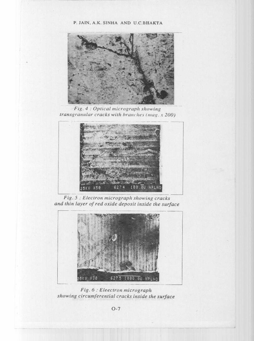
The morphology of the cracks
and deposits were examined by
SEM and analysed under Energy
Dispersive X-ray analyser. The
morphology could not reveal much
except the large number of machine
markings on the internal surface
of the tube. The cracks were
mainly around the circumference
about 10 mm away from the weld
as shown in micrographs no. 5, 6 and
7. The fracture surface was found
to contain black surface deposit.
The surface analysis at different
spots are given in Table 3. First
sample was found to contain chloride
and sulphur ions on the fracture
surface. The second sample was
containing the dye penetrant inside
crack showed large number of
elements on the surface as shown
in Table 3.
0-2

P. JAIN, A.K. SINHA AND U.C.BHAKTA
SAM and SIMS Examination
The presence of sulphur detected
by EDAX made the investigation
examine its compound in detail. This
was done by scanning Auger
Microprobe (SAM) andSecondary
Ion Mass Spectroscopic (SIMS)
techniques. The results indicate the
presence of organic compounds
containing carbon bonds withchloride and sulphur on the fracture
surface.
Visit To Manufacturer Site
The manufacturing site was
visited and discussed with the
concerning engineers to examine
possibilities of ingress of residual
contaminants found inside the spool
pieces. The spool pieces are made
by sub vendors. The heat treatment
requirements of coil are based on the
radius of bending and availability of
time before despatching to
commission the boiler in time.
and operation. Based on the authors
experience, knowledge and results of
the findings and discussion with engineer
at operation and manufacturing site, it is
believed that the stress corrosion had
taken place in presence of hydrolysible
chloride generated by residual
contaminants carried over from
manufacturing site when the metal temp.
was more than 100°C. It is not possible
to establish the stage of operation or
commissioning where stress, (residual
plus operating tensile stress) had
exceeded the threshold stress which led
to SCC. The other possible causes i.e.,
caustic accumulation has already been
ruled out because the pH of the deposits
on surface was neutral. The chloride
evidence and the mode of failure i.e.,
transgranular with branching made us to
conclude that chloride and excessive
residual tensile stress present in the spool
piece caused this type of failure. It was
believed that no further crack initiation
and propagation would not take place
after several operating hours and
hydraulic test had already taken place.
Discussion
The transgranular cracks withbranching observed under the opticalmicroscope and chloride presencedetected by surface analyticaltechniques confirmed the evidenceof SCC of austenitic stainless steeltype 347 H. It was important toknow at which stage crack initiationand propagation had taken place inorder to take suitable measures toprevent the forced outages. Wetherefore, examined all the stagesi.e., manufacturing, transit, storage,erection, alkali boil out, acidcleaning, hydraulic test, preservation
Conclusion1. The failure is due to chloride
induced stress corrosion cracking.2. New cracks generation is not
expected. However, it is believedthat the cracks already existingmay propagate due to mechanicalstresses during operation.
References1. Proceeding of Stress Corrosion
Cracking and HydrogenEmbrittlement of Iron BaseAlloys NACE, June 1973.
2. Proceeding of Americans PowerConference, 1976, Vol 38,pp.298-310.
0-3

Sample
S p 0 0 1piece no. I
Spoolpiece no.2
P. JAIN, A.K. SINHA AND U.C.BHAKTA
Table - 1
Chemical Composition of the Austenitic
Stainless Steel of Final Super Heater
(Element Analysis Wt%) Material
C S Cr Ni Mo identifiedby AISI
0.063 0.0077 17.26 10.13 0.69 AISI347hardness7 5 R BBHN 150
0.059 0.0073 17.65 9.56 0.68 AISI347hardness7 5 R BBHN 180
* Nb=(Nb+Ta)(alloy analyser Model 9266 USA), (C.S.analyser LECO)
Table - 2Elemental Analysis of Super Heater Tube of Unit No. 3 of FSTPS Collectedon. 29.6.88 Analysed by EDAX at NPL Sample No. I at Different Points
Element Weight %Point I Point 11 Point III Point Point
Fe 71.58 71.69 95.64 89.58 72.17
Cr 19.41 13.93 1.57 6.26 15.55
Ni 8.36 5.96 0.76 2.24 8.25
Mn -- 3.03 1.35 1.76 3.81
S 0.65 1.25 0.68 0.15 0.22
Cl 1.34 -- -- --
Na 2.02 -- -- --
K 0.45 -- -- --
Ca 0.45 -- -- --
0-4
Irw} Iw4W Rf^iu111^ipNFININIMtiwN^ ^^xoia7ipRo^^ANRaM1A1ANA^^^1^ IIII'
it

P. JAIN, A.K. SINHA AND U.C.BHAKTA
Table - 3Elemental Analysis of Super Heater Tube of Unit No. 3 of FSTPS Collected
on. 6.7.88 Analysed by EDAX at NPL Sample No. 2 at Different Points
Element Weight %Point I Point II Point III Point IV Point V Point VI
Fe 72.87 74.75 90.03 89.39 90.37 91.31
Cr 13.68 1.81 1.91 3.23 3.40 2.85
Ni 6.59 12.39 2.42 4.28 2.74 2.68
Mn 4.61 2.37 1.00 3.73 1.24 2.07
Cu 1.50 0.99 -- -- -- --
S -- -- -- -- -- 0.14
Cl -- 0.44 0.22
P 0.75 6.62 3.61 0.87 0.26 0.29
Ca -- 0.40 0.18 0.34 0.33 0.18
Al -- -- -- -- 0.71 --
Si 0.22 0.85 0.17 0.78 0.48
Fig. 3 : Optical micrographs showingtransgranular cracks with branching . (mag. x 100)
0-5

P. JAIN, A.K. SINHA AND U.C.BHAKTA
Fig. 7 : Eleectron micrograph
showing wide cracks around the circumference
SHFI 74Temp.540°C
SA 213 T34711
4.5 nim -- '17r N _ -' ( N StabilisedAust . Stainless
Welding Cracks 23rd
JointsILssy .2 2nd/88(IPW) Loo p 8/2/88
Pressure
Induction F/ N - Steel)
Thickness I Spool8.8 mm - ^^ -*-- -_SA213 TP347 11
(Niobium
1
Cracks
(SCC)
1415 Assay. 3rd
loop 29/6/8822nd Assay. 3rdtube 2/7/88
Failure location_of Spool Piece
Fig. I Final Super Heater Assy.
Manual stabilished
Welding Austenitic stainless
Joints steel)(MIG \" h I
Fig. 2 : Spool Piece Joining Two
(Coil) Showing Failure Location of Dissimilar Metal T22 and T347
Spool Piece
0-6
4-u 7q'1 iN aqu , ^ n o^ N^u
1t i ^ I I + u9111/ gnwr^R IN - rae ^Y wlYtw^
1^ t IIII ^i. k
P. JAIN, A.K. SINHA AND U.C.BHAKTA
Fig. 4 : Optical micrograph showing
transgranular cracks with branches (mag. x 200)
Fig. 5 : Electron micrograph showing cracksand thin layer of red oxide deposit inside the surface
Fig. 6 : Eleectron micrographshowing circumferential cracks inside the surface
0-7