Embed Size (px)
Citation preview
P c/ U.S. Deportment of Transportution
Fedeml Aviation
Advisory Circular
Subject: POWERPLANT INSTALLATION AND PROPULSION SYSTEM COMPONENT FIRE PROTECTION TEST METHODS, STANDARDS, AND CRITERIA.
Date: 2/6/W ACNo: 20- 135 Initiated by: ANM- 110 Change:
1 PURPOSE. This advisory circular (AC) provides guidance for use in demonstrating compliance with the powerplant fire protection requirements of the Federal Aviation Regulations (FAR). Included in this document are methods for fire testing of materials and components used in the propulsion engines and APU installations, and in areas adjacent to designated fire zones, as well as the rationale for these methods. Since the method of compliance presented in this AC is not mandatory, the terms "shall" and "must," as used in this AC, apply only to an applicant who chooses to follow this particular method without deviation.
2 RELATED FAR SECTIONS. The applicable FAR sections are listed in appendix 1 of this AC.
3 BACKGROUND. Although 5 1.1 of the FAR provides general definitions for the terms "fireproof" and "fire resistant," these definitions do not specify heat intensity, temperature levels, duration (exposure time), or an appropriate wall thickness or other dimensional characteristics for the purpose intended. With the advent of surface coatings (i.e., ablative/ intumescent), composites, and metal honeycomb for acoustically treated ducting, cowling, and other components which may form a part of the nacelle firewall, applicant confusion sometimes exists as to how compliance can be shown, particularly with respect to the definition of "fireproof" and "fire resistant" as defined in 5 1.1.
4 DEFINITIONS. apply
For the purposes of this AC, the following definitions . .
a. Fireproof: The capability of a material or component to withstand, as well as or better than steel, a 2000°F flame (+15O'F) for 15 minutes minimum, while still fulfilling its design purpose. The term "fireproof," when applied to materials and parts used to confine fires within designated fire zones, means that the material or part will perform this function under conditions likely to occur in such zones and will withstand a 2000°F flame (2150°F) for 15 minutes minimum.
b Fire Resistant: fluid:carrying lines,
When applied to powerplant installations such as flammable fluid system components, wiring, air ducts,
fittings and powerplant controls, "fire resistant" means the capability of a material or component to perform its intended functions under the heat and other conditions likely to occur at the particular location and to withstand a
. .
AC ZO- 135 216190
2000°F flame (+15O"F) for 5 minutes minimum. (Example: A fire resistant hose which will withstand a 2000°F flame for 5 minutes.)
Y
c. Engine Case Burnthroush: A fire condition within the engine which burns through the engine case, allowing a high pressure and high temperature gas stream to escape from the engine.
d flame:
Heat Flux Density: The rate of thermal energy in BTU/ft2-set of the One of the following devices shall be used to measure heat flux
density of the test flame:
(1) Calorimeter: The calorimeter to be used in testing must be a O-15.0 BTU/ft'-set (O-17.0 W/cm2) Calorimeter, accurate to & 3 percent.
(2) BTU Heat Transfer Device: See FAA Powerplant Engineering Report No. 3A (appendix 2 of this AC) for fabrication details of a copper tube device used to measure heat flux density.
NOTE: In accordance with Powerplant Report 3A, the copper tube shall be set up without any type of backing plate behind the copper tube.
e. Thermocouples: The thermocouples to be used should be bare junction l/16 to l/8-inch metal sheathed, ceramic packed, chromel-alumel, thermocouples with nominal 22 to 30 AWG (America1 Wire Gage) size conductors or equivalent. An air aspirated, shielded, thermocouple should not be used.
5 . FIRE PROTECTION PRINCIPLES AND OBJECTIVES.
a. The primary objectives of fireproof and fire resistant materials and components are to contain and isolate a fire and prevent other sources of fuel or air from feeding the existing fire, and to ensure that components of the engine control system will function effectively to permit a safe shutdown of the engine or APU and safe feathering of the propeller.
b. To demonstrate satisfactory containment capability, the materials or components must have adequate strength for the foreseen flight and operating loads under the conditions of a fire to allow proper fire detection, flightcrew recognition, and subsequent corrective action. In addition gaseous emissions from fire protection materials shall be precluded from entering the cabin air conditioning system.
c. Fire testing should simulate the likely fire environment to prove the materials and components will provide the necessary fire containment to meet the above objectives when exposed to a fire situation in service.
d. The descriptors "fireproof" and "fire resistant" differ only in the time duration that the material or component should maintain its integrity or perform its function. "Fire resistant" means the material or component will function and maintain its integrity for a minimum of 5
2 Par 4
2/6/N AC 20-135
minutes when exposed to a 2000°F flame temperature. "Fireproof" means the material or component will maintain its integrity and function for a minimum of 15 minutes when exposed to a 2000°F flame temperature.
6 meet
FIRE TEST EQUIPMENT STANDARDS AND TEST CRITERIA. Fire tests should and produce the following conditions and environment:
a. Test Equipment Criteria.
(1) Specified flame impingement temperature, heat flux density, and flame distribution.
(2) Critical actual operating loads and environmental conditions (air and fluid flow rates, pressures, structural loads, and the like).
(3) Specified fire and heat flux exposure duration.
b . Burner Eauipment: Heat flux density and temperature capability.
(1) The basic torch or burner requirements are that the flame should produce a 2000°F temperature within l/4 inch of the specimen and engulf or provide representative impingement coverage, dependent on specimen size. In addition, the burner or torch should provide a heat flux density of at least 9.3 BTU/f?-set or 4500 BTU/hr using the BTU heat transfer device, unless it can be shown that the heat flux density for the configuration under test will not inherently affect the results of the test (ref. paragraph d(4) below).
(2) Procedure: The burner shall be lit, allowing a 5-minute warm up. Conduct the calibration for heat flux density and obtain a flame temperature of 2OOO*F. Immediately after successfully completing the calibration, rotate or move the burner to the test specimen, maintaining the same distance of the specimen from the burner as the thermocouples/heat flux density device were from the burner during burner calibration. Do not shut off the burner between the calibration and the actual test. Ensure the thermocouple(s) is positioned in the flame, l/4 inch in front of the test specimen.
c. Acceptable Burner/Torch Configuration. Depending on the specific application, the following burners have been used:
(1) The type specified in Powerplant Engineering Report No. 3A (see appendix 2, Nos. 1, 5, and 6). This burner has been used to test flammable fluid-carrying components, cowling, composite materials, firewall materials, fuel and hydraulic hoses, and other similar applications.
(2) SAE 401 Burner (standard). This burner has been used for testing fire detectors, associated electrical wiring, and similar
' . applications and is specified in various Technical Standard Orders (TSO)
Par 5
AC 20- 135 216190 _
and military standards. NOTE: This burner should not be used for powerplant installation fire testing in accordance with this AC.
(3) SAE 401 Burner adjusted to increase the output to at least 9.3 Btu/ft*-set heat flux density. This adjusted burner has been used to test firewall materials, composite materials, cowling, electrical wiring, fuel flowmeters, firewall fittings, and other components.
(4) Propane and oxy-acetylene torch-standard and diverging nozzles. The propane or oxy-acetylene burner has been used for wiring, flow meters, firewall penetrations, and other "small" component type applications.
(5) Miscellaneous burners have been found acceptable by the FAA for the intended applications. Component and material fire testing has been accomplished using the manufacturer's choice of burner, provided acceptability by the FAA has been determined with respect to flame size/impingement area and heat flux density, and the temperature at the test article was 2OOOOF. The adequacy of the burner depends on the size of the component, installation considerations, and on the flame completely engulfing the exposed portion or "face" of the component, or covering a representative portion of sheet material.
d . Acceptable Test Criteria and Philosophy.
(1) The test for demonstrating compliance with the criteria for "fireproof" and "fire resistant" materials, components, and fittings is to expose the specimen to the required flame temperature and heat flux density for the required time (15 minutes for "fireproof" and 5 minutes for "fire resistant"). The specimen shall withstand flame penetration and not exhibit backside ignition for the required test time. Sheet materials and panels shall be tested by exposing a sample size approximately 10 inches on a side (lO"x1O", or a size appropriate for the intended application) to a flame from an acceptable burner at the test operating conditions outlined in paragraph 7. The flame size and temperatures shall be sufficient to maintain the required test temperature and heat flux density over an area of approximately 5"x5" for sheet materials and panels.
(2) Fittings used in firewalls and in fire zones shall be completely enveloped in the flame on the side that would normally be exposed to fire in the fire zone. The fittings shall be mounted in a manner simulating the actual installation, and fluid lines or tubing may be connected to both ends of the fitting to simulate the installation that would be present during a typical fire event. However, for the testing of fluid-fittings, there should be no fluid in the line on the engine side of the fitting in the fire zone, since the fire may have been caused by a failure of the line to the fitting under evaluation. Likewise, if failure of the line on the engine side of the firewall could drain the fluid from that portion of the line upstream of the firewall, up to the fluid shutoff valve, then the lines connected to both sides of the fitting should not
4 Par 6
Z/6/90 AC 20435
contain fluid for this testing. If the fitting is part of the shutoff valve, then the line behind or upstream of the valve should contain fluid. For operational components, such as check valves, lines, etc., the flame should completely envelop the unit.
(3) Technical Standard Order, TSO-C53a, Fuel and Engine Oil System Hose Assemblies, and TSOC75, Hydraulic Hose Assemblies, specify hose assembly fire resistance requirements. These hose assemblies should be exposed to a 2000°F flame for 5 minutes while maintaining the fuel or oil at critical (minimum or maximum) operating flow rates and pressures without evidence of any leakage. The 5-minute exposure provides a reasonable time for the flightcrew to recognize a fire condition, shut down the appropriate engine, and close the appropriate shutoff valve(s), thus shutting off a liquid flow to the engine compartment. It is important to evaluate the particular installation and obtain the minimum flow rate over the entire operating envelope. Although the TSO specifies a flow rate in gallons per minute of 3 to 5 times the (ID)', ID measured in inches, experience has shown, for example, that a hydraulic system drain or return line not under system demand can have no flow or a flow quite a bit less than that specified by 3 times (ID)'. The lower flow rate should then be used for the fire resistant or fireproof testing. The fire test procedure for hoses is outlined in FAA Powerplant Engineering Report No. 3A, (see appendix 2, Nos. 1, 5, and 6).
(4) The operational criteria required for various components depends on the kind of component to be tested. For example, if the unit is an oil line routed through a fire zone with the shutoff valve located outside and downstream of the fire zone, the line should withstand the test flame, without leakage or failure, for 15 minutes. If the unit under test is a shutoff valve located in the engine compartment fire zone, the valve should be exposed to the burner or flame for 5 minutes. The valve should not leak and should be able to be closed by normal application means at the end of the 5-minute exposure. After the valve has been closed, it is to be exposed to the flame for an additional 10 minutes, and the valve should not leak. Operational components should be subjected to the fire tests in every installation, unless similarity to previously approved configurations . can be shown, or they are made of steel or copper based alloys, or they are of such construction that their capability to operate satisfactorily under fire conditions is obvious.
.
(5) Electrical and mechanical controls (cables, electrical wires, drive links, etc.) for components such as shutoff valves located in the engine compartment or other designated fire zones are required to be "fire resistant." These shall be tested at a 2000°F temperature for 5 minutes. At the end of 5 minutes, the control shall perform its intended function without failure or malfunction. The flame should completely envelop the control and the end fittings and connections from one direction, all as a unit. Where
l a control rods or cables are to be tested, a typical section is all that is
Par 6
AC 200 135 216190
required to be evaluated. About 8 inches of the typical section will suffice in most tests, including the end connections and fittings. For testing cable controls, the normal rigging load should be simulated. Control rods which act in compression to operate their component should have the flame applied over the center portion of the rod length where the column compression action will most likely cause failure of the material. Flammable fluid shutoff valve controls should be tested for fire resistance in each installation, except where the cables or rods are purely tension controls and constructed of steel or other materials shown to be “fire resistant" or are designed such that their operation in fire conditions is obvious.
(6) The following minimum thickness materials are considered acceptable for use in firewalls or shrouds for non structural/non load- carrying applications, without being subjected to additional fire tests:
(i) Stainless steel sheet, .015 inch thick.
(ii) Mild steel sheet protected against corrosion, .018 inch thick.
(iii) Titanium sheet, .016 inch thick.
(iv) Monel metal sheet, .018 inch thick.
(v) Steel or copper base alloy firewall fittings/fasteners.
NOTE: Distortion of thin sheet materials and the subsequent gapping at lap joints or between rivets is difficult to predict; therefore, testing of the simulated installation is necessary to prove the integrity of the design. However, rivet pitches of 2 inches or less on non load-carrying titanium firewalls of .020 inch or steel firewalls of .018 inch are acceptable without further testing.
(7) In every applicat approval for the fire test ver for the fireproof and fire res the FAA office responsible for
ion the applicant should coordinate and obtain ification plan and other certification testing istant aspects of the proposed installation with
the project.
(8) At the conclusion of the testing, a report, including photographs, which describes the fire test results and addresses the pertinent items identified in this advisory circular should be submitted for FAA approval.
7 . FIRE PROTECTION INSTALLATION AND DESIGN FEATURES.
a. Structural Operatins Environment. The structural static and dynamic loading to be simulated during the testing is a function of the component or material and the intended use and location, and should be
6 Par 6
AC 20- 135 2/ 6190
addressed in the test plan. Firewall or component structural loading conditions must be identified and incorporated in the fire test setup. Flexible hoses are fire tested at anticipated fuel or oil internal pressures, flow rates, and vibratory conditions. The test is intended to simulate aircraft powerplant fire conditions, with the fuel, oil flow, and pressures at critical operating conditions.
b. Desiqn and Application Factors. There are a number of other important factors which can influence the test conditions required to substantiate firewalls and fire resistant surfaces. These considerations are classified into two categories. One is the "intended use" of the firewall or fire resistant surface. For example, is its intended use a cowl door or the inner wall of an engine fan exhaust duct or an inlet duct, or an isolating diaphragm with its primary purpose being a firewall? The second category relates to the firewall or fire resistant surface construction. Is it a complex composite structure bonded with resin and coated with a fire retardant, or is it an acoustic panel, or simply a stainless steel, titanium, or other basic metallic configuration? Typically, panels representative of the proposed structure (approximately l-l/Z by 2 feet) have been acceptable for demonstrating fire protection capability.
(1) “Intended Use" Test Criteria.
(i) If the firewall is a diaphragm or simple separation type non load-carrying bulkhead in a nacelle area with low ventilation and
\ circulation air flow and a small pressure load, a simple fire test at ambient '-. ~-. environmental laboratory conditions is acceptable to demonstrate fireproof '\ properties.
(ii) If the firewall is the nacelle cowling with approximately l/2 psi or less nacelle pressurization, scrubbing airflow may be utilized without consideration for having to run the test with nacelle pressurization.
(iii) If the firewall is an engine fan air exit duct or inlet adapter, "cool side" (backside) pressure and airflow conditions should be properly simulated during the testing. The test should be performed with the airflow and pressure the duct will normally be exposed to during critical power operating conditions for the initial 5 minutes and at windmilling conditions for the additional 10 minutes of the fire test, if this is the most severe heat condition. Fan exhaust ducts normally have their critical differential pressures existing across the duct at sea level, takeoff conditions. Inlet adapter type ducting will usually be at the maximum pressure when the engine is shut down in flight and allowed to windmill. These operating conditions should be determined by the applicant for use in the fire test. Typically, unprotected acoustic honeycomb specimens which fail this test will rupture due to loss of
Par 7 7
AC 200 135 2/6/90
strength under pressure during the first few minutes of testing, allowing air flow into the fire zone.
(iv) The test criteria in paragraph 'Ib(l)(iii) above, addressing the addition of airflow to a firezone during a fire condition, also applies to cooling air ducts, bleed air ducts, etc., located or routed within the fire zone.
(v) Aircraft engines with turbochargers operate at elevated temperatures and pressures within the engine compartment. Components adjacent to the turbocharger and exhaust systems should be evaluated for operation at these elevated temperatures and pressures. Also, any flammable fluid-carrying component or other system should be evaluated for a possible exhaust system component failure with resultant exhaust gas leakage. When those turbochargers are used for cabin pressurization, all air inlet ducts within the engine compartment should be evaluated for component burnthrough or release of noxious fumes within the cabin ventilation system.
(2) Firewall Construction Test Considerations. Bonded construction firewalls (composites or bonded metal matrix), in addition to being pressurized during testing, may need to be vibrated. This should be accomplished for all specimens with a sprayed, painted-on, or bonded-on protective coating intended to insulate the base material from the fire conditions. Past tests have shown some ablative and intumescent coatings become extremely brittle when exposed to flames. Vibration can cause the coating to flake off, exposing the base material. Current experience has not supported the use of an intumescent coating as an acceptable fire protection coating, because the coatings have lacked durability and exhibited poor adhesion characteristics in service. For composites or other "new" materials, more than one test panel may be required to show repeatability of the configuration.
C. Outsassing. A characteristic of bonded construction firewall materials and seal materials is the outgassing of the volatile constituents of the bonding resins or seal materials. This can occur from either the hot or cool side surface of the specimens during the test. These gasses are, in most instances, highly flammable. Ignition occurring on the cool side is unacceptable in passing the fire test. Where the cool side surface is exposed, visual observations will suffice to note if ignition has occurred. However, if the specimen is subjected to pressure loading during the test, or the cool side is hidden from view, then other methods to detect the ignition should be defined. It should be noted that some acoustically treated ducts are of metal construction, and the face sheets are bonded to the honeycomb core with resins which can exhibit outgassing. For these types of construction, no "cool side" ignition is allowed and verification is required.
CAUTION: Specimen size should be large enough to prevent flame wraparound of the specimen edge to provide a more accurate simulation of the actual installation.
Par 7
2/6/W AC 20-135
(1) Upon initial application of the test torch flame, minor flareup at the flame impingement area may occur; however, continuous burning or a significant increase of the flame pattern over the entire specimen is unacceptable. Ignition of the backside as well as penetration are the other anomalies which are cause to reject the component. Excessive outgassing, especially from composite construction, should be investigated to ensure the smoke will not ignite. Additional testing of samples should be requested to ensure that:
(i) Any surface flareup is self extinguishing and does not burn after removal of the test flame and,
(ii) Self re-ignition of the material does not occur when the flame is removed.
(2) If the gases emitted during the fire tests can enter the personnel compartment, the gases must be evaluated for their toxicity, volatility, and possible impairment of the crew or passengers.
d. Unique Desiqn Testins Considerations.
(1) The applicant should evaluate firewall designs, putting special emphasis on fuel and oil lines, cowling and/or bleed duct, and other firewall penetration points to determine the need for a specific fire test setup and incorporation of the penetrations in the firewall test specimen. As noted in paragraph 6d(2), flammable fluid-carrying lines and fittings need careful consideration. The use of previously approved corrosion-resistant steel or equivalent material is considered satisfactory without further tests. Use of aluminum alloy for any size line/fitting on either side of a firewall should be avoided. An evaluation of the specific installation configuration and actual minimum flow rates should be accomplished to determine fire resistant or fireproof capability. Previous tests (appendix 2, No. 3) have shown aluminum couplings (3/4 inch or larger) have leaked after exposure to the test flame for 5 minutes with nominal 30 psi pressure and a fluid flow rate in gallons per minute equal to 5 times the (ID)‘, ID measured in inches. All sizes of aluminum fittings up to 2 inches failed the "no flow" conditions. Five minutes is acceptable for fire resistant tubing; however, all firewall fittings/penetrations are required to maintain the integrity of the firewall without flame penetration or leakage for 15 minutes. Other designs which require special considerations are butt-joint seals between firewall diaphragms, cowl doors and where a cowl door is part of the firewall, seals between the doors, and drain/vent masts interfacing with the doors. Special fire tests of these "kiss" seals will be necessary to ensure the capability of the overall firewall.
Par 7
AC 20-135 2/6/W
NOTE: When dedicated protection devices or specific procedures or techniques are required to provide fire protection for an installation, development of periodic maintenance or requirements for inspection of these devices or techniques is required so that continued airworthiness is assured.
(2) For engine cowling and nacelles of small airplanes and helicopters, the fire resistant requirements of 5 23.1193(c) and 5 27.1193(d) have been interpreted to allow use of any material shown to be equivalent to aluminum alloy. Cowlings are subject to airflow over one or both sides, which greatly improves the fire resistant capability of the aluminum and has been found to be acceptable. For example, a .04-inch aluminum panel with an 80 Kt minimum scrubbing airflow over the backside has been shown to maintain its integrity when subjected to a 2000°F flame for 15 minutes.
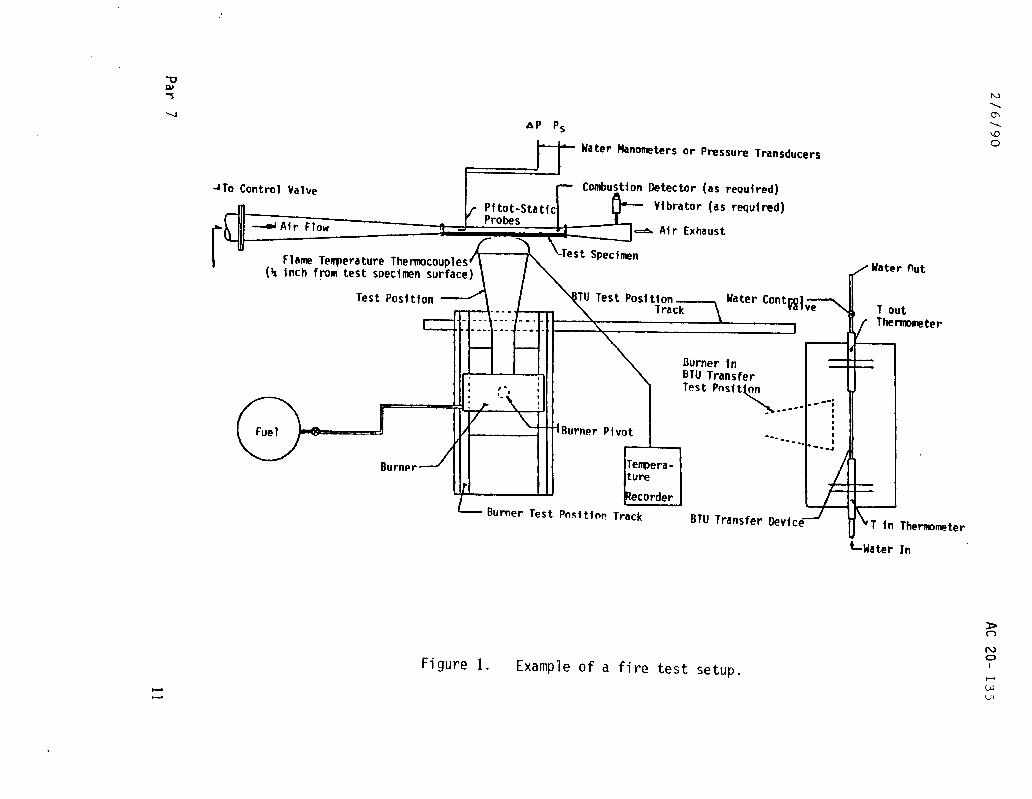
e. Special Test Consideration. In tests, particularly where testing is conducted using a burner other than one specified in Powerplant Engineering Report No. 3A, anomalies may be encountered due to torch blast effects and local hot spots created due to nonuniform heating of the specimens. These anomalies may be overcome with carefully designed burner tube extensions which spread the flame over a larger surface, as described in the report. An example of a fire test setup is shown in Figure 1.
10 Par 7
AP P,
Hater hnomters or Pressure Transducers
~TO Control Valve In
Combustton Detector (as rewfred)
Pi tmt-wrtir Vibrator (as reauiredl
L 41: &Air Flow d Air Exhaust UJ rrsmmmm T I Iawe
-mr.ur*..u- ~errper-a wre tL--------* - - I nemocoup resr (a inch fpm test soecimen surface) Water Out
Test Polcitht~ -- - --. "."I, Water Contt;gl'-\ ve
- --/ Burner m-m Burner PI
L- Burner Test Posttlor!
\
Burner In BTU Transfer Test
I
Track BTU Transfer
LWater
ter
Thermome ter
In
Figure 1. Example of a fire test setup.
AC 200 135 2/6/90
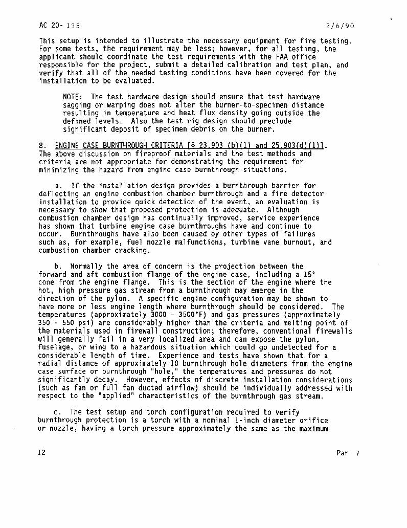
This setup is intended to illustrate the necessary equipment for fire testing. For some tests, the requirement may be less; however, for all testing, the applicant should coordinate the test requirements with the FAA office responsible for the project, submit a detailed calibration and test plan, and verify that all of the needed testing conditions have been covered for the installation to be evaluated.
NOTE: The test hardware design should ensure that test hardware sagging or warping does not alter the burner-to-specimen distance resulting in temperature and heat flux density going outside the defined levels. Also the test rig design should preclude significant deposit of specimen debris on the burner.
8 . ENGINE CASE BURNTHROUGH CRITERIA K 23.903 (b)(l) and 25.903(d)(I)l. The above discussion on fireproof materials and the test methods and criteria are not appropriate for demonstrating the requirement for minimizing the hazard from engine case burnthrough situations.
a. If the installation design provides a burnthrough barrier for deflecting an engine combustion chamber burnthrough and a fire detector installation to provide quick detection of the event, an evaluation is necessary to show that proposed protection is adequate. Although combustion chamber design has continually improved, service experience has shown that turbine engine case burnthroughs have and continue to occur. Burnthroughs have also been caused by other types of failures such as, for example, fuel nozzle malfunctions, turbine vane burnout, and combustion chamber cracking.
b. Normally the area of concern is the projection between the forward and aft combustion flange of the engine case, including a 15" cone from the engine flange. This is the section of the engine where the hot, high pressure gas stream from a burnthrough may emerge in the direction of the pylon. A specific engine configuration may be shown to have more or less engine length where burnthrough should be considered. The temperatures (approximately 3000 - 3500°F) and gas pressures (approximately 350 - 550 psi) are considerably higher than the criteria and melting point of the materials used in firewall construction; therefore, conventional firewalls will generally fail in a very localized area and can expose the pylon, fuselage, or wing to a hazardous situation which could go undetected for a considerable length of time. Experience and tests have shown that for a radial distance of approximately 10 burnthrough hole diameters from the engine case surface or burnthrough "hole," the temperatures and pressures do not significantly decay. However, effects of discrete installation considerations (such as fan or full fan ducted airflow) should be individually addressed with respect to the "applied" characteristics of the burnthrough gas stream.
.
c. The test setup and torch configuration required to verify burnthrough protection is a torch with a nominal l-inch diameter orifice or nozzle, having a torch pressure approximately the same as the maximum
12 Par 7
2/6/N AC 20-135
burner pressure of the installed engine. The test article (burnthrough barrier) should be located at the same distance and supported similar to the proposed installation. The engine burnthrough criterion requires that under these operating conditions the barrier will maintain its integrity for a minimum of 3 minutes when exposed to a minimum flame temperature of 3000°F.
d. The proposed certification test plan, including the above operating environment, should be submitted to the FAA office responsible for the project for coordination and acceptance prior to conducting the fire testing.
Daniel P. Salvano Acting Director, Aircraft Certification Service
Par 8 13

2/6/90 AC 20-135 Appendix 1
APPENDIX 1. RELATED FAR SECTIONS
The sections listed below identify requirements that will necessitate the use of the fire testing methods and standards outlined in this AC to show compliance with the applicable powerplant and APU regulations in FAR Parts 1, 23, 25, 27, 29 and 33.
FAR PART SECTION
1 1 1 .
23 23.859, 23.863, 23.903, 23.1013 23.1091, 23.1121, 23.1123, 23.1141, 23.1182, 23.1183, 23.1189, 23.1191, 23.1192, and 23.1193.
25 25.859, 25.863, 25.867, 25.903, 25.1013, 25.1091, 25.1103, 25.1121, 25.1123, 25.1165, 25.1181, 25.1182, 25.1183, 25.1189, 25.1191, 25.1192, 25.1193, 25.1201, 25.1203, and 25.1207.
27 27.859, 27.863, 27.903, 27.1123, 27.1183, 27.1185, 27.1189, 27.1191, 27.1193, 27.1194, and 27.1195.
29 29.859, 29.863, 29.903, 29.1025, 29.1103, 29.1121, 29.1123, 29.1165, 29.1183, 29.1189, 29.1191, 29.1193, 29.1194, 29.1201, and 29.1203.
33 33.17, 33.71.
1 (and 2)

2/6/90 AC 20435 Appendix 2
APPENDIX 2. RELATED READING MATERIAL
1 . Federal Aviation Administration: Powerplant Engineering Report No. 3A, Standard Fire Test Apparatus and Procedure, Revised March 1978.
2 . Federal Aviation Administration: Report No. FAA-RD-76-213, Re-evaluation of Burner Characteristics for Fire Resistance Tests, dated January 1977.
3 . Federal Aviation Administration: Report No. DS-67-4, A Study of the Fire Resistance of Aluminum Alloy Tubing and Fittings, April 1967.
4 . Department of Commerce, Civil Aeronautics Administration, Safety Regulation Release No. 259, Compliance of Equipment and Materials Used in Air Carrier Aircraft with Fire Prevention Requirements, August 26, 1947. .
5 . Society of Automotive Engineers: AS 1055B, Fire Testing of Flexible Hose, Tube Assemblies, Coils, Fittings and Similar System Components, Revised March 1, 1978.
6 . Society of Automotive Engineers: AIR 1377A, Fire Test Equipment for Flexible Hose and Tube Assemblies, Revised January 1980.
7 . FAA Technical Standard Order, TSOC42, Propeller Feathering Hose Assemblies.
8 l FAA Technical Standard Order, TSO-C53a, Fuel and Engine Oil System Hose Assemblies.
9 l FAA Technical Standard Order, TSO-C75, Hydraulic Hose Assemblies.
1 (and 2)