Embed Size (px)
Citation preview
Operation and Maintenance Manual
Hydro-JettingTank
DLCV-H
P a r t n e r s h i p f r o m s u n t o s u n
01
COMPANY MESSAGE
As of 1964, with the development of the Rotary Hoe, activated by a stationary motor which later was adapted to be used in a coastal brush mower, Ipacol became a benchmark for Brazilian agriculture. In the beginning of the eighties, with the development of the first auger type distributors for organic fertilizer and limestone, Ipacol became synonymous with quality in the agricultural sector. These tools were the first Ipacol products, and are still sales leaders in these categories in Brazil today. After 40 years of work, the Ipacol brand has been consolidated in Brazil and several other countries through a broad dealer network that allow a vast distribution of equipment and parts, as well as providing technical assistance to a large number of consumers. Also, Ipacol offers a team of technicians that instruct and support the dealers, and also provide demonstrators who carry out demos that put the equipment products to practical use, according to the needs of the farmer. This way, Ipacol, who follows the constant development of the agricultural market and is always concerned about the environment, expanded their manufacturing campus, building a new modern industrial park with a factory and a leisure area of approximately 35,000 m² developed in perfect harmony with the natural structure found there. All this was done in order to be able to continue to constantly offer various and innovative lines of equipment and tools, capable of performing with high levels of productivity and low cost with the efficiency that Ipacol is already known for.
Ipacol, preserving nature from sun up to sun down. “We want to continue to meet every demand, to offe the farmer more comfort and satisfaction."
The equipment and the respective technical specification contained here are subject to alteration without prior warning.
The specification and amounts listed may vary depending of the version and the equipment’s options.All the images and drawings are only for illustrative purposes.

Read and understand the manual instructions before operating the machine; The operation of this machine should be limited to the qualified person; Nobody under eighteen years of age is allowed to operate the machine;
The employer has the responsibility to instruct every employee as to the safety of the operation; Notices, warnings and precautions help prevent possible bodily harm from happening to you or to others;
Do not operate unless all the safety protection gear is in the correct location; Make sure that everyone knows the instructions before operating the machine;
Unqualified people should remain outside the work area; Keep hands, feet, clothing, belts, and chains far from any moving parts;
When loading when the machine is in operation, watch out for rotating parts because they might cause severe damage or death; Always stop the machines for adjustments, service, or cleaning;
Periodically review the safety instructions with all the users; Contact the reseller or factory if you don’t understand how something works or any part of the manual;
The best operator is the careful operator;
02P a r t n e r s h i p f r o m s u n t o s u n
Read before using the Machine
SAFETYTHIS SAFETY ALERT SYMBOL CAN BE FOUND THROUGHOUT THIS MANUAL TO DRAW YOUR ATTENTION TO THE INSTRUCTIONS THAT INVOLVE YOUR
PERSONAL SAFETY AND THE SAFETY OF OTHERS. NOT FOLLOWING THESE INSTRUCTIONS CAN LEAD TO INJURY OR DEATH.
Operation and Maintenance ManualParts Catalog
st1 Edition – June 2011
03
IPACOL MÁQUINAS AGRÍCOLAS LTDA.Factory: Rua Quatro, 257 - CP 168 - Distrito Industrial - CEP 95330-000 - Veranópolis - RSPh : www.ipacol.com.br E-mail: [email protected] - [email protected]
one: 54 3441 9550 / 9650 - WebsiteP a r t n e r s h i p f r o m s u n t o s u n
Read before using the Machine
SAFETY

This manual was developed in order to supply the necessary information to ensure the safety and correct operation of the equipment, as well as it maintenance, in a simple and direct manner, ensuring better performance and the longest possible useful life, avoiding premature wear and unnecessary costs.
The products have various applications. Therefore, the information presented here is general and does not intend to cover every single possible application.
The information included in the manufacturer manuals of the suppliers of the applied equipment should prevail over the information included in this manual.
Ipacol Máquinas Agrícolas Ltda. reserves the right to modify the product at any time without therefore, incurring any obligation regarding the previously supplied products.
INTRODUCTION
04 P a r t n e r s h i p f r o m s u n t o s u n

WARRANTY CERTIFICATE 3 DEALER COPY
WARRANTY CERTIFICATE 2 FACTORY COPY
20
WARRANTY CERTIFICATE 1 CLIENT COPY
PageITEM
PageITEM
MAINTENANCE
WARRANTYA2 – Operation of Ignition Switch
A1 – Power Takeoff Operation
Safety
Main Parts
7Main characteristics
PageITEM
OPERATION
Defects and Likely Solutions
INDEX
27
28
29
A3 – Loading by Vacuum Suction with 4" Valve
A4 – Unloading by Gravity
A5 – Unloading with Pressure
A6 - Cleaning the Tank after Unloading
Liquid Ring Pump Maintenance 21
8
9
10
11
12
13
14
15
16
17
A7 – Closing the Tank Manhole
A8 – Hydro-jetting Operation
18Liquid Ring Pump Functioning
05
Usage and Functionality Instructions 10

To ensure the correct operation and longer useful life of this equipment, we recommend following the listed instructions in order to take advantage of its large capacity and operational simplicity.
OPERATION
06
IPACOL MÁQUINAS AGRÍCOLAS LTDA.Factory: Rua Quatro, 257 - CP 168 - Distrito Industrial - CEP 95330-000 - Veranópolis - RSPh ite: www.ipacol.com.br E-mail: [email protected] - [email protected]
one: 54 3441 9550 / 9650 - Webs
P a r t n e r s h i p f r o m s u n t o s u n

Main Characteristics DLCV-H
Hydro-jetting, done with a truck equipped with a
water reservoir, either high pressure or flow,
depending on the type of obstruction, accompanied
by accessories, required PPEs and qualified
technicians for the execution of services in sewer
networks, grease traps, flooded areas, potable
water networks, foam treys, water reservoirs,
inspection boxes, boilers, distillation channels,
grooves, condensers, exit conductors, sewage
collection networks and underground areas,
columns of waste, potable, and rain water, vertical
and horizontal residential collection columns,
condominiums, retail, and industrial space.
The tank is built in a cylindrical shape, with a
capacity of 8,000 liters to 20,000 liters, out of
carbon steel material that is 4.75 mm thick, with
an internal surge head, reinforcement rings,
external brackets, and a 500 liter water reservoir
for pump cooling. A reel with 100 meters of hose
and an adjustable nozzle for various types of
cleaning for culverts and residential sewage,
loading water using a hydrant or a manhole.
Vacuum pump and high pressure hydro-jetting
pump. Level displays to visualize loading; Hose
support; Rear manhole with a hinge for complete
opening in order to be able to do the inspection
and internal cleaning of the tank; Surrounding
mudguards; Barrel support, Tool box; Reverse
switch to do the vacuum and pressure work.
07

K
Main Parts
08
DLCV-H - Hydro-Jetting Tank
AB C D E
G
F
I
H
J
L
Read before using the Machine
SAFETYSAFETY
A Rear Manhole
B – Kettle
C – Purifier
D – 4 Way Valve
E – Water Reservoir for the
Pump
F – Motor and Motor
Protection
G – Liquid Ring Pump
H – Level Display
I – Reel
J – Control Panel
K – High Pressure Pump
L – Ladder
–

SAFETY
09
Read before using the Machine
Read before using the Machine
SAFETYSAFETY
For better operation and safety, Always observe the manovacuometer display because it will
show the vacuum or work pressure.
Never exceed the vacuum or pressure levels that are appropriate for the job.
Products aspirated inside the pump will harm its functionality and durability.
The system has a relief valve, for safety.
Note:
Even with the safety device, never exceed the volume as indicated by the level visor.
Keep a distance of at least 20 meters from the work area.
In any cleaning and maintenance operation, never leave the equipment running.
Use appropriate clothing with protection.

Read before using the Machine
Read before using the Machine
SAFETYSAFETY
EQUIPMENT USAGE AND FUNCTIONALITY
INSTRUCTIONS
(A1) – Power Takeoff Operation (Liquid Ring Pump)
1- Make sure the truck transmission is in "neutral."2- Start the engine.3- Step on the clutch, wait about five seconds, and engage the power takeoff, using the switch located on the left side of the steering wheel.Note: The switch inside the truck, on the left side of the steering wheel, is to activate the vacuum pump. The activation of the high pressure pump is done on the right rear side of the truck.4- Slowly release the clutch to avoid impacts in the coupling of the power takeoff and the truck's gearbox.5- From this point on, operate the equipment and adjust the acceleration of the work using the truck’s accelerator.6- After the operation, step on the clutch again, wait approximately 5 seconds, and disengage the power takeoff, using the switch described in item 3 (above).7- Turn off the ignition key.
Observations:* Never Change the Gear of the Truck After the Power Takeoff is Engaged.* Always use the Clutch to Engage and Disengage the Power Takeoff.Approximate System Rotations (rpm)
MOTOR ROTATIONSROTATIONS OF THE VACUUM PUMP
1200 1250 1300 1350 1400936 975 1014 1053 1092
10
11
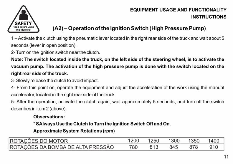
ROTAÇÕES DO MOTORROTAÇÕES DA BOMBA DE ALTA PRESSÃO
1200 1250 1300 1350 1400780 813 845 878 910
Read before using the Machine
Read before using the Machine
SAFETYSAFETY
EQUIPMENT USAGE AND FUNCTIONALITY
INSTRUCTIONS
(A2) – Operation of the Ignition Switch (High Pressure Pump)
1 – Activate the clutch using the pneumatic lever located in the right rear side of the truck and wait about 5
seconds (lever in open position).
2- Turn on the ignition switch near the clutch.
Note: The switch located inside the truck, on the left side of the steering wheel, is to activate the
vacuum pump. The activation of the high pressure pump is done with the switch located on the
right rear side of the truck.
3- Slowly release the clutch to avoid impact.
4- From this point on, operate the equipment and adjust the acceleration of the work using the manual
accelerator, located in the right rear side of the truck.
5- After the operation, activate the clutch again, wait approximately 5 seconds, and turn off the switch
describes in item 2 (above).
Observations:
* SAlways Use the Clutch to Turn the Ignition Switch Off and On.
Approximate System Rotations (rpm)

Read before using the Machine
Read before using the Machine
SAFETYSAFETY
EQUIPMENT USAGE AND FUNCTIONALITY
INSTRUCTIONS
(A3) – Loading by Vacuum Suction with 4" Valve
1- Couple the suction hose in the loading valve inlet, located in the rear side of the tank. It is the
connection that is slightly higher that the unloading valve outlet.
2- Open the loading valve.
3- Close the unloading valve.
4- Close the purifier drain valve.
5- Activate the Power Takeoff (Vacuum Pump), following the same procedures described in item A1.
6- Position the hose in the work location.
7- Adjust the vehicle's engine to the appropriate rotation for the job to be executed, avoiding maximum
acceleration if there is no need for it.
8- Accompany the loading, using the tank level displays.
9- After loading, close the loading valve.
10- Reduce the motor acceleration and turn off the pump, following the same procedures described in
item A1.
11- Open the purifier drain valve and keep it in that condition until the liquid ring pump is operated again.
12- Disconnect and put away the suction hose;
12
Read before using the Machine
Read before using the Machine
SAFETYSAFETY
EQUIPMENT USAGE AND FUNCTIONALITY
INSTRUCTIONS
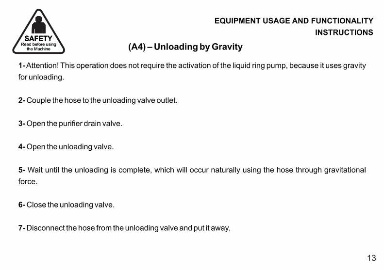
(A4) – Unloading by Gravity
1- Attention! This operation does not require the activation of the liquid ring pump, because it uses gravity
for unloading.
2- Couple the hose to the unloading valve outlet.
3- Open the purifier drain valve.
4- Open the unloading valve.
5- Wait until the unloading is complete, which will occur naturally using the hose through gravitational
force.
6- Close the unloading valve.
7- Disconnect the hose from the unloading valve and put it away.
13
Read before using the Machine
Read before using the Machine
SAFETYSAFETY
EQUIPMENT USAGE AND FUNCTIONALITY
INSTRUCTIONS
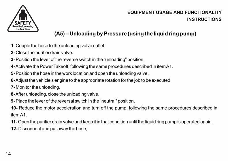
(A5) – Unloading by Pressure (using the liquid ring pump)
1- Couple the hose to the unloading valve outlet.
2- Close the purifier drain valve.
3- Position the lever of the reverse switch in the “unloading” position.
4- Activate the Power Takeoff, following the same procedures described in item A1.
5- Position the hose in the work location and open the unloading valve.
6- Adjust the vehicle's engine to the appropriate rotation for the job to be executed.
7- Monitor the unloading.
8- After unloading, close the unloading valve.
9- Place the lever of the reversal switch in the “neutral" position.
10- Reduce the motor acceleration and turn off the pump, following the same procedures described in
item A1.
11- Open the purifier drain valve and keep it in that condition until the liquid ring pump is operated again.
12- Disconnect and put away the hose;
14

Read before using the Machine
Read before using the Machine
SAFETYSAFETY
EQUIPMENT USAGE AND FUNCTIONALITY
INSTRUCTIONS
(A6) - Cleaning the Tank after Unloading
1- Proceed loading with vacuum suction as described in item A3.
2- When the pump is functioning (i.e. already causing a vacuum in the tank), release the hydraulic locks with
the hydraulic command located in the rear of the equipment.
3- Return the lever of the reversal switch in the “neutral" position (center of the reversal switch).
4- Turn off the power takeoff as described in item A1.
5- Dump the rear manhole, using the hydraulic command that corresponds to the indicator sign.
6- Proceed with cleaning the tank.
7- After cleaning, make sure the sealing rubber of the manhole is clean and undamaged, and then close the
manhole as described in the following item.
15

Read before using the Machine
Read before using the Machine
SAFETYSAFETY
EQUIPMENT USAGE AND FUNCTIONALITY
INSTRUCTIONS
(A7) – Closing the Tank Manhole
1- Close the manhole using the hydraulic command located on the right rear side of the equipment, making
sure that, when using the hydraulic dumping system, the hydraulic pump is activated.
2- To activate the hydraulic pump, turn the ignition key that activated the high pressure pump
(interconnected systems).
3- Accelerate the motor to the appropriate rotation.
4- Warning! To activate the Hydraulic Pump, make sure that the water reservoir has enough water to
circulate in the high pressure pump.
5- Proceed with the closing of the manhole until near the hydraulic locks. Make sure all the locks are totally
open to ensure that there will not be any impact of the manhole lock with the closing wedge. If any closing
cylinder underwent spontaneous movement during the work, activate tge hydraulic opening of the locks
again.
6- Attention: When the equipment is new and the sealing rubber has not settled, the closing locks make
require some effort. If this occurs, with the manhole resting on the rubber, activate the vacuum with all of the
outlets closed, and the force of the vacuum will help close it.
7- After the manhole if closed and locked, decelerate the motor and turn off the ignition as described
previously.
16

Read before using the Machine
Read before using the Machine
SAFETYSAFETY
EQUIPMENT USAGE AND FUNCTIONALITY
INSTRUCTIONS
(A8) – Hydro-jetting Operation (high pressure pump)
1- Before beginning this procedure, do not forget to open the valves that feed the pump, which are located
under the equipment near the high pressure pump. The pump may never function without water.
2- Unroll the hose from the reel to operate, using the hydraulic command of the right rear side to the truck.
Obviously, for the reel’s hydraulic motor to work, the hydraulic pump needs to be activated.
3- Position the hose in the operation location. Warning! Never turn on the high pressure pump with the hose
loose.
4- Turn the ignition key that activated the high pressure pump, as described in item A2.
5- Control the water volume of the tank using visors.
6- Regulate the pressure and work flow by acceleration, using the manual accelerator.
Not every effort needs maximum acceleration and this precaution ensures a longer useful life for the
equipment.
7- Execute the cleaning operation making sure the hose is not dragging on an abrasive surface. Use the
manhole guide and, if that is not possible, use a piece of the hose with a larger diameter to pass the high
pressure hose through.
8- At the end of the operation, decelerate and turn off the ignition switch, as described in item A2. Recoil the
hose on the reel using the hose guide so the loops are properly rolled.
17
Read before using the Machine
Read before using the Machine
SAFETYSAFETY
OPERATING INSTRUCTIONS FOR THE
LIQUID RING PUMP
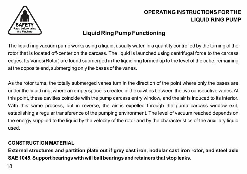
Liquid Ring Pump Functioning
The liquid ring vacuum pump works using a liquid, usually water, in a quantity controlled by the turning of the
rotor that is located off-center on the carcass. The liquid is launched using centrifugal force to the carcass
edges. Its Vanes(Rotor) are found submerged in the liquid ring formed up to the level of the cube, remaining
at the opposite end, submerging only the bases of the vanes.
As the rotor turns, the totally submerged vanes turn in the direction of the point where only the bases are
under the liquid ring, where an empty space is created in the cavities between the two consecutive vanes. At
this point, these cavities coincide with the pump carcass entry window, and the air is induced to its interior.
With this same process, but in reverse, the air is expelled through the pump carcass window exit,
establishing a regular transference of the pumping environment. The level of vacuum reached depends on
the energy supplied to the liquid by the velocity of the rotor and by the characteristics of the auxiliary liquid
used.
CONSTRUCTION MATERIAL
External structures and partition plate out if grey cast iron, nodular cast iron rotor, and steel axle
SAE 1045. Support bearings with will ball bearings and retainers that stop leaks.
18

The following information is necessary to ensure the maintenance of the equipment in a simple and direct manner, to ensure its
performance and its useful life.
To clarify other procedures or doubts, please consult technical assistance of the dealer or the factory.
19
Maintenance
IPACOL MÁQUINAS AGRÍCOLAS LTDA.Factory: Rua Quatro, 257 - CP 168 - Distrito Industrial - CEP 95330-000 - Veranópolis - RSPhone : www.ipacol.com.br E-mail: [email protected] - [email protected]
: 54 3441 9550 / 9650 - WebsiteP a r t n e r s h i p f r o m s u n t o s u n
Read before using the Machine
SAFETY

DEFECT
2- Insufficient vacuum.
CAUSE SOLUTION
1- No vacuum
a) Close the drain.b) Find and correct the cause of the leak.
a) Release the spheres by sending positive pressure to the tank or by releasing it with your hands.b) Remove and clean the hoses of the vacuum circuit.
3- Vacuum interrupted before the tank is finished loading.
a) Probable obstruction in the suction hose.
a) Check and unclog.
Read before using the Machine
SAFETY
DEFECTS AND LIKELY
SOLUTIONS
a) The purifier drain is open.b) The system has a false air entry.
a) The light spheres for sealing the bell jar and the purifier are caught on the base.b) There may be an obstruction in the vacuum circuit.
20

21
MAINTENANCERead before using
the Machine
SAFETY
LIQUID RING PUMP MAINTENANCE
NoteIts noise level is often less than that of the truck motor.
Preventative WorkMaintain the bearing oil level (level display). Check every 600 hours of work.Oil used: SAE 90 (see brands and equivalence on page 24).Cleaning the suction filter of the water for the pump every 220 hours of work, or when changing the water, or when you feel the power of the pump has diminished.Change the water in the reservoir that supplies the pump (recommended 400 liters) every 220 hours.
We recommend the addition of soluble oil (see types and equivalents on page 25).Always maintain the proper functioning of the float system for the purifier and the bell jar so no foreign material enters the pump.
Guidelines for Exchanging RetainersIf a retainer becomes damaged during use, it is easy to perceive, just note if the nylon hose that comes from under the pump and continues until the curved pipe of the reversal switch has water passage with soluble oil. If this occurs, it is a sign that there is water passage from the rotor chamber to the intermediary chamber, thus requiring the need to exchange the retainers.To do that, follow the instructions on the following pages.
The only moving component of the pump is the rotor, attached to the axle. It turns without any contact between the components, so there is no friction between them. This construction method practically eliminates the need for maintenance under normal usage conditions.

Read before using the Machine
SAFETY
LIQUID RING PUMP MAINTENANCE
ROTOR CARCASS (Water sealing)
1- Attach the pump to a secure location, using the perforation of the rear foot.
2- Loosen the 7 screws that secure the pump carcass.
Note: If you loosen, along with the pump carcass, the pump plate that are joined together with an Allen
screw.
3- Remove the pump carcass.
4- Unscrew to rotor.
Note: Turn to the left. To release the rotor, lock it and turn the pulley with a tool (e.g. Wrench).
5- Loosen the 4 screws that attach the rotor carcass.
6- Remove the carcass.
7- From the rear of the carcass, with a wedge type tool and a hammer, beat of the retainers until you
remove them. Note the position of the retainers.
8- Install the new retainers, one by one, noting their position.
9- Attention: Do not strike with a pointed tool. Use a device with the same diameter as the retainer and hit
in the center of it so the retainer enters evenly and is not damaged.
10- Now do the opposite for the assembly.
11 - Note: In the carcass fit and in the housing for the rear screws, apply silicone paste.
22

Read before using the Machine
SAFETY
LIQUID RING PUMP MAINTENANCE
BEARING CARCASS (oil sealing)
1- Attach the pump to a secure location, using the perforation of the rear foot.
2- Drain the oil from the bearing carcass. For this purpose, use the plug under the axle pulley.
3- Remove the axle pulley.
4- First loosen the screw that attaches it and then remove the pulley (if necessary, use a puller).
5- Loosen the 4 screws of the rear flange.
6- Remove the rear flange.
7- Remove the retainer with a wedge type tool and a hammer, striking on the rear of the retainer.
Note the position of the retainer. Install the new retainer carefully, following the recommendations
of item 9 of the previous page. Now do the opposite for the assembly.
23

BRAND
OILSAE 90
HIPÓIDE 90
PETROBRÁS
LUBRAXTRM S-90
SHELL
SPIRAXHD-90
TEXACO
MULTIGEAREP-90
CASTROL
UNITRON90
ESSO
ESSOGP 90
IPIRANGA
IPERGEROLEP 90
MANGUINHOSQUÍMICA
Read before using the Machine
SAFETY
LIQUID RING PUMP MAINTENANCE
The liquid ring pump, under normal usage conditions, does not require special maintenance and can be done by the user, but the precautions below should be followed to always maintain the equipment in order.
* Periodically check and maintain the oil level of the liquid ring pump.* Always use the specified oil, being careful to not surpass the maximum level, because the excess oil will be thrown out by the vent.
* Check periodically if the feeding valve is leaking.* Check the water level of the reservoir for the liquid ring pump using the level display installed in the left side of the reservoir.* To prevent corrosion in internal areas of the system, soluble oil must be added, which will act as an anti-corrosive agent.* Only synthetic and semi-synthetic soluble oils are recommended. Mineral oils, despite being listed below, should only be used where the oils mentioned above cannot be found, because during work it causes foam to form, which can be dragged by the air and expelled through the reversal switch. They are the following oils, in the proportions listed on the table of the following page:
24

BRAND
MILKMINERAL
WALQUÍMICA
EMUCORTEX
PETROBRÁS
LUBRAX FC37
SHELL
DROMUSB
TEXACO
SOLÚVELC
CASTROL
COOLEDGEB-1
ESSO
KUTWELL40
IPIRANGA
SOLÚVEL2
SOLUBLE MINERAL OIL
BRAND
MODEL
WALQUÍMICA
SOLCORTEXR
VALVOLINE
LUBRICORB-420
SHELL
DROMUSB
TEXACO
TEXSOLEP
CASTROL
CLEAREDGE6515
SEMI-SYNTHETIC SOLUBLE OIL
BRAND
MODEL
WALQUÍMICA
SOLCORTEXR
VALVOLINE
LUBRICORS-400
SHELL
DROMUSE
TEXACO
TEXSOLR
CASTROL
SYNTILO 2
SYNTHETIC SOLUBLE OIL
SOLUBLE MINERAL OIL
380 LITERS
SPECIFIC QUANTITIES OF SOLUBLE OIL AND WATER (FOR A TOTAL OF 400 LITERS)
WATER
SEMI-SYNTHETIC SOLUBLE OIL SYNTHETIC SOLUBLE OIL
OIL WATER OIL WATER OIL
20 LITERS 380 LITERS 388 LITERS20 LITERS 12 LITERS
Note: The approximate capacity of the water reservoir for the pump is 500 liters.Note: It is necessary that the water reservoir has an empty space of approximately 100 liters for the circulation of air.
LIQUID RING PUMP MAINTENANCE
25

Read before using the Machine
SAFETY
LIQUID RING PUMP MAINTENANCE
* Check the “Y” filter weekly, and if needed clean the filtering element.
To do that, just follow the instructions below:
1 – Close the valve before the “Y” filter.
2 – Release the lid located below the “Y” filter, using its own key.
3 – After the removal of the lid, remove the filtering element (stainless steel screen) that is in the
filter.
4 – Clean the screen, put it back where it belongs, and close the lid.
5 – Open the valve for feeding the pump.
Note: For the “Y” filter to be kept clean, what is important is the quality of the water that is
placed in the reservoir (it should be free of impurities, because they will get stuck in the
filter).
25

PRODUCT:
Client Name:
Address:
Telephone: City: State:
Farm: Telephone:
Equipment model: Serial Number: Year:
Fiscal Invoice:
Resale
Person at Dealership responsible for the technical delivery:
Signature of person responsible for Delivery Dealership Stamp and Signature Client Signature
__________________________________________________________________________________________
______________________________________________________________________________________
__________________________________________________________________________________________
_______________________ ________________________________________ ______________
_______________________________________________ ___________________________________
_________________________________ __________________ ____________
___________________________________________________ Date: _______ / ________ / ________
: __________________________________________________________________________________________
__________________________________________________
___________________________________ ____________________________ __________________________
IPACOL MÁQUINAS AGRÍCOLAS LTDA., guarantees the product specified herein against any defect dully proven bythe factory, that meet the following conditions:I. The warranty is valid for 6 (six) months as of the purchase date of the equipment by the user.II. The warranty covers the repair or free supply of parts that have a manufacturing defect.III. The warranty does not apply under the following conditions: Improper machine use; Damage caused by accidents; Normal usage wear;Damage caused by carelessness during transportation or storage; Lack of or improper use of lubricants; Disregarding instructions and recommendations for usage and operation and maintenance care; Modifications, adaptations or application of non-original parts; Abuse or natural danger.IV. Damaged parts that need to be exchanged or repaired should be forwarded by the dealer to the factory, along with a report of the warranty and a copy of the fiscal invoice of the product purchase.V. The 2nd (second) copy of this WARRANTY CERTIFICATE should be sent to the factory properly filled out and with the respective signatures in order to comply with the warranty terms expressed herein.VI. The factory reserves the right to modify its products without prior warning, while complying with current legislation regarding the availability of replacement parts.
CLIENT WARRANTY CONTROL
WARRANTY CERTIFICATE
P a r t n e r s h i p f r o m s u n t o s u n

PRODUCT:
Client Name:
Address:
Telephone: City: State:
Farm: Telephone:
Equipment model: Serial Number: Year:
Fiscal Invoice:
Resale
Person at Dealership responsible for the technical delivery:
Signature of person responsible for Delivery Dealership Stamp and Signature Client Signature
__________________________________________________________________________________________
______________________________________________________________________________________
__________________________________________________________________________________________
_______________________ ________________________________________ ______________
_______________________________________________ ___________________________________
_________________________________ __________________ ____________
___________________________________________________ Date: _______ / ________ / ________
: __________________________________________________________________________________________
__________________________________________________
___________________________________ ____________________________ __________________________
IPACOL MÁQUINAS AGRÍCOLAS LTDA., guarantees the product specified herein against any defect dully proven bythe factory, that meet the following conditions:I. The warranty is valid for 6 (six) months as of the purchase date of the equipment by the user.II. The warranty covers the repair or free supply of parts that have a manufacturing defect.III. The warranty does not apply under the following conditions: Improper machine use; Damage caused by accidents; Normal usage wear;Damage caused by carelessness during transportation or storage; Lack of or improper use of lubricants; Disregarding instructions and recommendations for usage and operation and maintenance care; Modifications, adaptations or application of non-original parts; Abuse or natural danger.IV. Damaged parts that need to be exchanged or repaired should be forwarded by the dealer to the factory, along with a report of the warranty and a copy of the fiscal invoice of the product purchase.V. The 2nd (second) copy of this WARRANTY CERTIFICATE should be sent to the factory properly filled out and with the respective signatures in order to comply with the warranty terms expressed herein.VI. The factory reserves the right to modify its products without prior warning, while complying with current legislation regarding the availability of replacement parts.
FACTORY WARRANTY CONTROL
WARRANTY CERTIFICATE
P a r t n e r s h i p f r o m s u n t o s u n

PRODUCT:
Client Name:
Address:
Telephone: City: State:
Farm: Telephone:
Equipment model: Serial Number: Year:
Fiscal Invoice:
Resale
Person at Dealership responsible for the technical delivery:
Signature of person responsible for Delivery Dealership Stamp and Signature Client Signature
__________________________________________________________________________________________
______________________________________________________________________________________
__________________________________________________________________________________________
_______________________ ________________________________________ ______________
_______________________________________________ ___________________________________
_________________________________ __________________ ____________
___________________________________________________ Date: _______ / ________ / ________
: __________________________________________________________________________________________
__________________________________________________
___________________________________ ____________________________ __________________________
IPACOL MÁQUINAS AGRÍCOLAS LTDA., guarantees the product specified herein against any defect dully proven bythe factory, that meet the following conditions:I. The warranty is valid for 6 (six) months as of the purchase date of the equipment by the user.II. The warranty covers the repair or free supply of parts that have a manufacturing defect.III. The warranty does not apply under the following conditions: Improper machine use; Damage caused by accidents; Normal usage wear;Damage caused by carelessness during transportation or storage; Lack of or improper use of lubricants; Disregarding instructions and recommendations for usage and operation and maintenance care; Modifications, adaptations or application of non-original parts; Abuse or natural danger.IV. Damaged parts that need to be exchanged or repaired should be forwarded by the dealer to the factory, along with a report of the warranty and a copy of the fiscal invoice of the product purchase.V. The 2nd (second) copy of this WARRANTY CERTIFICATE should be sent to the factory properly filled out and with the respective signatures in order to comply with the warranty terms expressed herein.VI. The factory reserves the right to modify its products without prior warning, while complying with current legislation regarding the availability of replacement parts.
DEALERSHIP WARRANTY CONTROL
WARRANTY CERTIFICATE
P a r t n e r s h i p f r o m s u n t o s u n

IPACOL MÁQUINAS AGRÍCOLAS LTDA.Factory: Rua Quatro, 257 - CP 168 - Distrito IndustrialCEP (Zip Code) 95330-000 - Veranópolis - RSE-mail: [email protected] - [email protected]
Phone: 54 3441 9550 / 9650 - www.ipacol.com.br P a r t n e r s h i p f r o m s u n t o s u n