Embed Size (px)
Citation preview

1
Copyright 2005-2015 Mountain Models
www.MountainModels.com
P-51 Mustang 1/12 Scale Electric Park Flyer
Wingspan: 37”, Wing Area: 254 sq. in., Weight: 15 to 19.5 oz Instructions Version 1.62, July 27, 2011
LIABILITY RELEASE In that Mountain Models has no control over the final assembly or material used for final assembly, no liability shall be assumed or accepted for any damage resulting from the use by the user of the final user-assembled product. By the act of using the user-assembled product, the user accepts all resulting liability. If the buyer is not prepared to accept the liability associated with the use of this product, the buyer is advised to return the kit immediately in new and unused condition. THIS PRODUCT IS NOT INTENDED FOR CHILDREN 12 YEARS OF AGE OR YOUNGER Warning: This product may contain chemicals known to the State of California to cause cancer or birth defects or other reproductive harm

2
Copyright 2005-2015 Mountain Models
Kit Contents:
1. CAD Plan Sheet 2. Instruction Manual 3. Laser Cut Balsa and Plywood Sheets (Bagged) 4. Vac-Formed Plastic Parts
Clear Canopy Cockpit with Seat Cowling Exhaust Stacks (Left and Right) Radiator Scoop (Top and Bottom)
5. Large Hardware Bag 2 ea. 1-3/4” DuBro Wheels 2 ea. Main Gear Wire (3/32” Dia. x 7”) Pushrod Wire (0.047” Dia. x 18”) Velcro Set, 4” (Loop and Pile) Velcro, Double Sided, 8” Thin Plastic Tube
6. Small Hardware Bag 2 ea. Landing Gear Wheel Bushings (Aluminum Tube) 2 ea. Fixed Gear Wheel Keepers (Star Locks) 2 ea. Retract Gear Wheel Keepers (Plastic Tube) 2 ea. 4-40 T-Nuts 2 ea. 4-40 x 1” Nylon Bolts ½” Tail Wheel Rare Earth Magnet 3/8” Dia. Steel Washer E-Z Hinge Material Screws, Gear Mount (8)
7. Pull-Pull Parts Bag 6 ea. Micro Servo Connector 6 ea. Servo Connector Backer 6 ea. Servo Connector Lock Screw 4 ea. Cotter Pin 8 ft. Pull-Pull Line
Recommended Items for Finishing:
1. 1 Roll Lightweight Covering (So-Lite or Similar) 2. Extra Covering or Trim Sheets for Details as Needed 3. Paint for Finishing Plastic Parts 4. GWS 50mm 2 or 4 Blade Spinner (or Similar) 5. Optional: GWS “Blue” Retracts
Suggested Electronics:
1. 4 Channel Transmitter Minimum (5 minimum for retracts) 2. 4 ea. Sub Micro Servos (HS-55, GWS Naro, or equivalent) 3. Optional: HS-55 (or similar in size and torque for retracts) 4. Y-Splitter for Aileron Servos (or 6ch RX with appropriate transmitter) 5. Optional: 2 ea. 6” Servo Extensions (if using servos with short wires) 6. Micro Receiver, (4 channel minimum, 5 channel minimum for retracts)

3
Copyright 2005-2015 Mountain Models
Brushed Power System:
1. GWS EPS350C-DS Motor/Gear Box 2. Micro Electronic Speed Control (10A Minimum) 3. GWS 10x8 (2-Blade or 4-Blade) Propeller 4. 8-Cell, 650 mAh NiMH Battery
Brushless Power System:
1. Himax 2015-4100 Brushless Motor, GWS Gearbox (“D”, 6.6:1) or Himax Gearbox (Recommended), 10x8 4-blade propeller, and a 3S LiPo battery.
2. Himax 2015-4100 Brushless Motor, GWS Gearbox (“C”, 5.53:1) or Himax Gearbox (Recommended), 10x8 2-blade propeller, and a 3S LiPo battery.
3. Himax 2015-5400 Brushless Motor, GWS Gearbox (“C”, 5.53:1) or Himax Gearbox (Recommended), 9x7 2-blade propeller with 3S LiPo or 10x8 4-blade propeller with 2S LiPo battery.
4. Himax 2015-5400 Brushless Motor, GWS Gearbox (“D”, 6.6:1) or Himax Gearbox (Recommended), 9x7 or 10x8 2-blade propeller, and 3S LiPo battery.
Other Items That You Should Have:
1. CA (Super Glue, thin and thick) 2. Plastic Wrap or Wax Paper 3. X-Acto Knife and Blades
GENERAL INFORMATION: Thank you for purchasing the Mountain Models 1/12 Scale P-51 Mustang Electric Park Flyer. We believe this model fits an area that has been largely ignored or done poorly to date. We strived to provide a laser cut kit that provides the builder a properly engineered, nicely finished, lightweight, great flying park flyer that is as scale as possible. Designed in 3D CAD, we used interlocking laser cut parts throughout, to make assembly as easy as possible, locking parts together for proper alignment and fit. This kit is designed for the novice to intermediate builder and the somewhat experienced pilot in mind. You should have some experience with tail draggers, knowing how to use the rudder and elevator on takeoff runs. Once in the air, however, even the novice can fly this model. If you don’t have tail dragger experience, get some help from someone that does and you’ll be fine flying this model. You’ll be the envy of pilots at your field when you show up with this model. They won’t believe what they’re seeing! Please let us know about your experiences building and flying this model. We look forward to customer feedback and want to know how you’re doing with it! Thank you, Brian Eberwein [email protected] Mountain Models 2935 N Lynndale Drive Appleton, WI 54914
ASSEMBLY ADVICE:
1. READ THE INSTRUCTIONS all the way through and study the plans BEFORE starting any work on this model! 2. Make sure you completed the above. Yes, this is important enough to state twice. 3. Tape the plans to your nice clean work surface and cover it with plastic wrap or wax paper. You do want to keep your work surface
clean and not glue your parts to the plans, right? 4. DO NOT REMOVE ANY PART FROM THE SHEETS UNTIL YOU NEED THEM. Some of the parts are delicate and you do
NOT want them laying around getting damaged before you need them. 5. DO NOT FORCE the fit of any part. If the fight seems too tight, stop, make sure you have the right part and it’s going in the right
way. If it’s still too tight, lightly sand the part so it fits. 6. DO NOT GLUE ANYTHING until you are told to do so. If you glue something before you are told, there is a chance that parts
after it may not be able to be assembled without modification or breakage. 7. Make solid glue joints. You will be tack gluing in some steps and reinforcing those joints later on. Make sure to reinforce the joints
when told, so you end up with a nice strong airframe.

4
Copyright 2005-2015 Mountain Models
FUSELAGE ASSEMBLY:
1. Remove the fuselage side parts from the 1/8” Balsa sheet. They are all on the same sheet. Match up all of the side pieces and make sure you have 2 of each one. If you only have one of a part, double check the sheet and find it. The first side you will be assembling is the LEFT side over the plans, with the text facing up. (This way, the text will be on the inside when you assemble the fuselage. Assemble the parts over the plan sheet as shown in the image below. If a part seems tight, double check and make sure you have the right one and it is oriented correctly. If, after double checking it is too tight, then lightly sand the mating surfaces until it fits nicely. Secure all joints with thin CA. Lay wax paper or plastic wrap over the completed left side and assemble the right side parts over it. Secure all joints with thin CA.
2. Remove the 3/32” Balsa F6 part from the sheet. Get the rare earth magnet from the bag. Turn F6 so the text is facing the work
surface. Press the magnet into the hole as shown in the image below. Use thin CA to secure the magnet in place.
3. Assemble the parts to make complete 1/8” F2, 1/16” F10, and 1/8” F7 formers over the plans. AFTER the parts are aligned
properly, secure with thin CA. make sure you get a good glue bond with the parts.
4. Remove the 1/8” Balsa F-28 parts from the sheet. Remove the 4-40 T-Nuts from the parts bag. Set the F-28 parts on the work
surface with the text facing up. Press the T-nuts into the holes in the parts, making sure they are in as far as they can go. Secure the nuts around the outside using thin CA. Be careful not to get glue n the threads.

5
Copyright 2005-2015 Mountain Models
5. Push the F28 parts into the completed F7 former as shown in the image below. Make SURE that the formers are positioned like they are in the image and the blind nuts are facing the right direction, otherwise, they won’t do their job of keeping the wing in place! After you have double checked that they are correct, make sure they are at a 90 degree angle to F7, and secure them with thin CA.
6. Press the F7 assembly from the last step into the F6 as shown in the image below, with side flush with the magnet facing away
from F7. Make sure that the triangular F28 parts are facing to the long end of F6 as shown. After you double check that they are oriented properly, make sure they are at a 90 degree angle to each other and secure with thin CA.
7. Press the 3/32” F5A and F8 parts onto the ends of F6, making sure they are on the correct ends. After everything lines up properly, make sure the formers are 90 degrees to F6 and secure with thin CA.
8. Do not glue anything until you are told to do so. Take the assembly from the previous step and carefully press it into place on the
fuselage RIGHT side as shown in the image below. DO NOT GLUE ANYTHING at this time.

6
Copyright 2005-2015 Mountain Models
9. Place the 1/16” F15 former flat on your work surface. Press the 1/16” F13 into place as shown in the image below. Make sure they are at 90 degrees to each other and secure with thin CA.
10. Do not glue anything until you are told to do so. Press the 1/8” F2 assemble into the fuselage RIGHT, making sure the text is facing
FORWARD. THIS IS IMPORTANT. Press the 1/16” F9, 1/16” F10, 1/16” F11, 1/16” F12, and 1/16” F13 into place but DO NOT glue them yet. Press the assembled F14/F15 piece into place as shown in the image below. DO NOT GLUE ANYTHING YET.
11. Assemble the fuselage LEFT to the assembly from step 10. DO NOT GLUE anything yet. Be careful and make sure all tabs are
fully pressed in/together and that everything is aligned properly. See the image below for what it will look like when you are done. Be gentle when pressing the side onto the formers. If something is tight, use light sandpaper on the joint.
12. Assemble 1/8” Balsa F1 to the fuselage assembly, making sure the text is facing FORWARD. This is IMPORTANT! Do NOT glue
it in yet. Use low-tac tape to hold it in place if you need.

7
Copyright 2005-2015 Mountain Models
13. Press the 1/8” F27 piece into place on the bottom front center of the fuselage as shown in the image below, but do NOT glue it yet. Make sure it is facing the right direction. Press the 3/32” F30 parts into place on the bottom front as shown in the image below, but do NOT glue it yet.
14. Press the 1/8” F24 piece into place on the fuselage front top as shown in the image below, but do NOT glue it yet.
15. Press the 1/8” F25 piece into place on the fuselage rear top as shown in the image below, but do NOT glue it yet.
16. Be gentle with the stringers in the next step, as they can break if you are not careful with them. If they don’t seem to fit, please
check to make sure they are oriented correctly, and if they are still tight, lightly sand the mating surfaces until they fit nicely. Press the 1/8” F26 piece into place on the fuselage rear bottom center as shown in the image below, but do NOT glue it yet. Press the two (2) 3/32” F29 pieces into place on the fuselage rear bottom, between F7 and F11 as shown below, but do NOT glue them yet. Press the two (2) 3/32” F321 pieces into place on the fuselage rear bottom, between formers F11 and F14 as shown in the image below, but do NOT glue them yet.
8
Copyright 2005-2015 Mountain Models
17. Install the 1/8” F5B and 1/8’ F32 parts in the fuselage as shown in the image below, but do NOT glue them in yet.
18. Double check and make sure that all parts are tabbed together and seated fully. Okay, the moment you’ve been waiting for, grab
your thin CA bottle and get ready to glue! Place the fuselage over the plans to make sure it is straight and untwisted. Start with the fuselage where F6 tabs into the sides, and apply thin CA to the joints, making sure the parts are fully seated. Secure F7 to the fuselage sides with thin CA. From F7, work your way forward, making sure all parts are pressed together and secure the formers to the sides with thin CA. After that is done, start at F7 and work your way to the back end, securing all of the formers to the fuselage sides with thin CA. Make sure to keep an eye on the fuselage and ensure that it is straight and not twisted along the way. After the formers are glued, go ahead and secure the stringers with thin CA. Your fuselage should be glued together now. Make sure you do not forget any joints!
19. Find the 1/8” S12 piece and set it next to your fuselage. Apply thick CA to the S12 part and assemble it to the fuselage as shown in the image below. Make sure it is aligned with the F-15 part and pressed against the rear former.
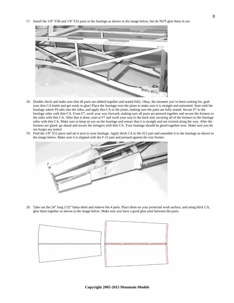
20. Take out the 24” long 1/32” balsa sheet and remove the 4 parts. Place them on your protected work surface, and using thick CA,
glue them together as shown in the image below. Make sure you have a good glue joint between the parts.

9
Copyright 2005-2015 Mountain Models
21. The larger of the 2 parts is the front sheeting and the other is the rear. Wet the front 1/32” sheet part with water on the side with the engraved lines. This will make it easier to conform to the fuselage. Place it on the fuselage with the engraved line on the inside. The lines are to help you position it. There will be a little hanging off the front, back, or both. This is okay as it will be trimmed later. There may also be a little extra on the outside edges. This is also okay as we will trim it later. Hold the piece in place with rubber bands until it dries completely. Check it every so often to make sure it hasn’t shifted.
22. Repeat the previous step for the rear sheet, but make sure that the back end of the sheet is lined up to the rear edge of F12. After
both sheets have dried completely, carry on to the next step.
23. Making sure that the front sheeting has not moved and is still properly aligned, turn the fuselage over and secure the 1/32” sheet to
the center 1/8” spine. Start gluing the sheet to the formers, pressing down to make sure it is in contact with all of the formers. Do not glue all the way to the outside edges yet. There may or may not be a slight overhang of the sheeting before trimming. The parts are cut slightly oversize to account for different sheets shrinking differently when wetted. Repeat this for the rear sheeting. Use a sharp X-Acto knife or sandpaper to CAREFULLY trim the sheeting to sit flush with the fuselage sides. After the sheeting lies down flush with the sides, go ahead and glue it down to the last part of the former and fuselage sides. There may or may not be a slight overhang of the sheeting before trimming. The parts are cut slightly oversize to account for different sheets shrinking differently when wetted. Repeat this for the rear sheeting. Take your time and be careful not to remove too much at a time.
24. Locate and remove the 1/8” C4 part from the sheet. Locate the steel washer from the parts bag. Use the engraved lines and sand between the engraved lines, down until the washer sits flush with the top surface of the C4 part. Remove a little material at a time to make sure you do not remove too much material.

10
Copyright 2005-2015 Mountain Models
25. Locate and remove the C1 and C5 parts from the 1/8” balsa sheet. Assemble them your work surface, making sure they are flat and secure the joints with thin CA. Make sure the joint between C1 and C4 is glued well.
26. Locate and remove C2 and C3 from the 3/32” balsa sheet. Place the assembly from the previous step with the washer DOWN.
Place the 3/32” balsa formers in position and secure the joints with thin CA, making sure they are at 90 degrees to the C1 part. MAKE SURE you glue them as shown in the image below, so the magnet will hold the canopy down!
27. Remove the motor stick parts from the 1/8” plywood sheet. Assemble it as shown in the image below. Be sure to make good glue
joints!
28. Set the fuselage, motor stick, and canopy frame aside in a safe place where it will not get damaged and continue onto the next
section.

11
Copyright 2005-2015 Mountain Models
TAIL FEATHERS ASSEMBLY:
1. Locate and remove the V1 to V7 parts on the 1/8” sheet. They are all on one sheet in the lower left corner. Assemble V1, V2, and V3 over the plan sheet, and secure with thin CA.
2. Place V7 in position as shown below, but do NOT glue it yet. Make sure it is pushed up against V1.
3. Assemble V6 as shown below, but do NOT glue it yet. Make sure the tabs from V1 and V2 are pushed fully into V6.

12
Copyright 2005-2015 Mountain Models
4. Locate and remove the V8 and V9 parts on the ½ sheet of 1/16” balsa. Assemble them as shown below, but do NOT glue them yet.
5. Press V5 into V6, making sure the tab is fully pressed in. Being careful not to damage the 1/16” ribs, press V4 into place, but do
NOT glue it yet. Make sure all of the parts are fully pressed together, the vertical fin is straight, and secure all joints with thin CA.
6. Locate and remove the R1 to R5 parts from the same 1/8” sheet used in the Vertical fin. They are all in the section next to the
vertical fin parts. Assemble R1, R2, R3, and R4 over the plan sheet and secure with thin CA as shown in the image below.
13
Copyright 2005-2015 Mountain Models
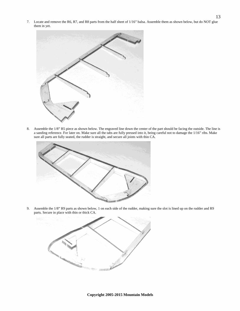
7. Locate and remove the R6, R7, and R8 parts from the half sheet of 1/16” balsa. Assemble them as shown below, but do NOT glue them in yet.
8. Assemble the 1/8” R5 piece as shown below. The engraved line down the center of the part should be facing the outside. The line is
a sanding reference. For later on. Make sure all the tabs are fully pressed into it, being careful not to damage the 1/16” ribs. Make sure all parts are fully seated, the rudder is straight, and secure all joints with thin CA.
9. Assemble the 1/8” R9 parts as shown below, 1 on each side of the rudder, making sure the slot is lined up on the rudder and R9
parts. Secure in place with thin or thick CA.

14
Copyright 2005-2015 Mountain Models
10. Assemble the 1/16” R10 parts, which are found on the half sheet of 1/16” balsa, as shown below, one on each side of the rudder. Make sure the slots are lined up and secure with thin or thick CA.
11. After all CA has finished drying, set the fin and rudder in a safe place and continue onto the next step. 12. Locate and remove the 1/8” stab parts from the 1/8” sheet. They are in the top section of the sheet. Lay them out as shown below. It
may be helpful to match up parts in pairs, then select one from each set for each side of the stab. Start with the outside parts, S1, S2, S3, and S4 and assemble them over the plan, but do NOT glue them yet. Then install the inside parts as shown on the plans. After all the parts are installed, secure all joints with thin CA, making sure the parts are flat on your building surface.
13. Locate and remove the elevator parts from the 1/8” balsa sheet. They are all in the same section on the sheet. Start with the outside
parts, E1, E2, E3, and E4, assembling them over the plan, but do NOT glue them yet. Install the inside pieces as shown on the plan. After all parts are fully assembled, make sure they are flat on your building surface and secure all joints with thin CA.
14. Locate the 1/8” dowel and cut it to length as shown on the elevator section of the plan sheet. Join the elevator halves over the plan
sheet using thick CA or epoxy. Make sure you get a good glue joint! After it has dried, set the tail feather assemblies aside and continue with the next section.
15
Copyright 2005-2015 Mountain Models
WING ASSEMBLY:
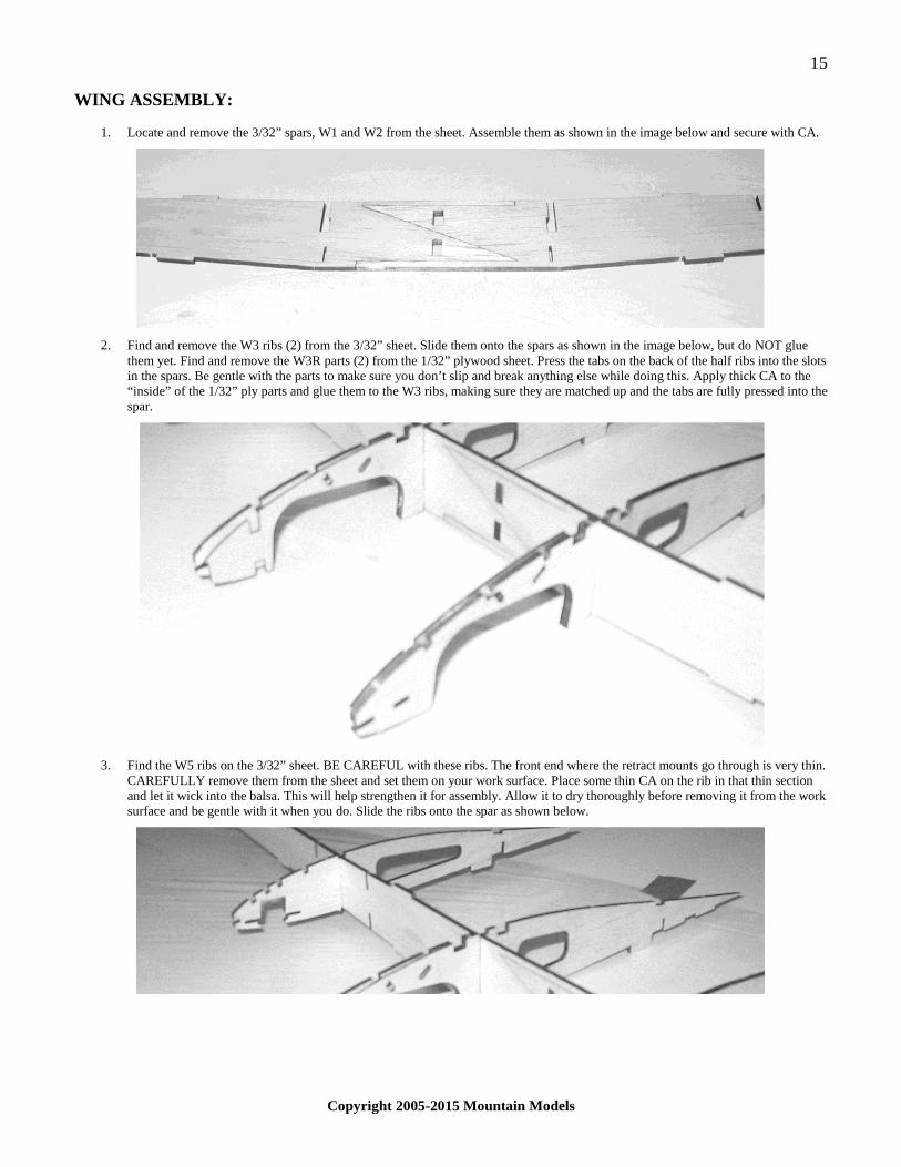
1. Locate and remove the 3/32” spars, W1 and W2 from the sheet. Assemble them as shown in the image below and secure with CA.
2. Find and remove the W3 ribs (2) from the 3/32” sheet. Slide them onto the spars as shown in the image below, but do NOT glue
them yet. Find and remove the W3R parts (2) from the 1/32” plywood sheet. Press the tabs on the back of the half ribs into the slots in the spars. Be gentle with the parts to make sure you don’t slip and break anything else while doing this. Apply thick CA to the “inside” of the 1/32” ply parts and glue them to the W3 ribs, making sure they are matched up and the tabs are fully pressed into the spar.
3. Find the W5 ribs on the 3/32” sheet. BE CAREFUL with these ribs. The front end where the retract mounts go through is very thin.
CAREFULLY remove them from the sheet and set them on your work surface. Place some thin CA on the rib in that thin section and let it wick into the balsa. This will help strengthen it for assembly. Allow it to dry thoroughly before removing it from the work surface and be gentle with it when you do. Slide the ribs onto the spar as shown below.

16
Copyright 2005-2015 Mountain Models
4. Find and remove the retract mounts from the 1/16” ply sheet. Press them through the slot in W5 as shown in the image below, making sure it is facing the right direction with the open end facing towards the center of the wing. BE CAREFULL when doing this and place your finger on the back side of W5 when pushing the retract mount through. If the small front section breaks off, you can glue it back on later after the wing is mostly assembled. Repeat this for the other side of the wing.
5. Locate and remove the W4 and W6 parts from the 1/16” plywood sheet. Press them into the notches in the spar and press the retract
mount tabs into the ribs. Do NOT glue them at this time. Repeat this for the other side of the wing.
6. Locate the W16 part on the 1/8” sheet. This part was on the balsa piece inside the C1 part. Press the tabs into the spar as shown
below, but do NOT glue it yet.

17
Copyright 2005-2015 Mountain Models
7. Locate the W17 part on the 1/8” sheet. This part was on the balsa piece inside the C1 part. Slide this part into the notch in the W16 part and place the tabs in the notches in the 1/32” W3R parts as shown below. Make sure it is pressed fully into the slot. Do NOT glue at this time.
8. Locate and remove the W21 part from the 1/16” plywood sheet. Install it as shown below. Make sure it is fully seated with the 2
W3 ribs and secure with thin CA. Line up the wing over the plans, making sure the center section is square and the ribs are fully pressed into the spar and all tabs are fully pressed into the notches and secure the center section pieces with thin CA.
9. Glue W29 onto the back of the center section of the spar as shown below, making sure it is flush top/bottom. Locate and remove
the W7, W8, and W9 ribs from the 1/16” sheets. Slide them into the slots on the spars. Locate and remove the W10 parts from the 1/16” sheets. Slide the W10 parts into the ribs from the bottom, making sure they are fully pressed into the slots. The W8 ribs tab into the W10 piece. Make sure it is fully pressed in. do NOT glue anything at this time. Repeat for the other side of the wing.

18
Copyright 2005-2015 Mountain Models
10. Locate and remove the W13 pieces from the 1/16” balsa sheet. Press the W13 pieces into place in the rib slots as shown below. Be careful around the W5 area not to break the front piece of the rib off. This would be the time to re-install the broken piece if you had problems with it earlier on the W5 front piece. The ends tab into the W3 and W9 ribs. Do NOT glue anything yet. Repeat for the other side of the wing.
11. Locate and remove the W14 and W15 pieces from the 1/16” balsa sheet. Press them onto the leading edge as shown in the image
below. Make sure they are pressed fully against the W13 piece. The text on these parts will be facing outward and up. Do NOT glue anything yet.
12. Locate and remove the “BOT” and “TOP” spar caps from the 1/16” balsa sheet. “BOT” means bottom, and “TOP” of course,
means top. Start with the bottom spar caps and press them on the notches in the ribs, making sure they are pushed up against the spar. There are 2 different sides, so make sure you have them oriented, text facing outward on the correct side. You will have to “crack” the spar caps on the bottom so they sit flush where they meet the center ribs. Turn the wing over and install the “TOP” spar caps.

19
Copyright 2005-2015 Mountain Models
13. Make sure all parts are fully seated and aligned. Place the wing on your work surface, left side down, with the tabs on the rear of the ribs resting on the work surface. Press down on the upper spar cap to make sure the caps are seated to the spar, and use thin CA to glue the lower spar cap to the spar. Use thin CA to glue all joints on the left wing half. Repeat for the right side of the wing.
14. Locate and remove the 1/16” rear pieces marked “B”. These are the bottom caps for the rear of the wing. The other 2 that look similar are the top ones. With the left wing panel flat on the building surface, set the top one in place as shown in the image below. Make sure it is fully in the notch in the ribs, and secure it with thin CA. Repeat for the other side of the wing. The caps do not need to be flush to the top the rear spar, but can sit at a “V” there.
15. Turn the wing over and install the top rear spar caps on each wing half, securing them with thin CA. The spar caps should be flush
in the center section as shown below.
16. Locate and remove the W20 parts from the 1/16” balsa sheet. Install them as shown below, making sure they are pushed fully into
the wing ribs, and secure with thin CA.

20
Copyright 2005-2015 Mountain Models
17. Locate and remove the W22 part from the 3/32” balsa sheet. Line up the holes with W21 and secure with CA. Make sure the holes line up! Sand the back end of this part to match the ribs on either side.
18. Locate and remove the W18 part from the 3/16” balsa sheet. Press it into place as shown in the image below and secure with thin
CA.
19. Locate and remove the W30 and W31 parts from the 1/8” balsa sheet. Install them as shown below, making sure they are on the
right side (W30 in front and W31 behind the spar) and secure them with thin CA. Make sure they are pressed down all the way.

21
Copyright 2005-2015 Mountain Models
20. Locate and remove the W19 wing tip parts from the 3/32” balsa sheet. Install them as shown in the image below, making sure the tabs are pushed in as far as they can go. Secure the parts with thin CA.
21. Locate and remove the RT3 and RT4 parts from the 3/16” balsa sheet. Install them as shown below. RT3 goes in the front, RT4
goes in the back. Make sure they are pushed in fully and secure them in place with thin CA.
22. Locate and remove the W25 and W26 parts from the 3/16” balsa sheet. Install them as shown below. Make sure you have them
oriented properly. Do NOT glue them at this time.

22
Copyright 2005-2015 Mountain Models
23. Locate and remove the W27 part from the 1/8” balsa sheet. Install it as shown in the first image. Do NOT glue it yet. Locate and remove the W28 part from the 1/8” balsa sheet. Install it as shown in the second image. Make sure the parts are flush with the rib where they meet it and secure all parts with thin CA.
24. Repeat steps 22 and 23 for the other half of the wing. 25. Locate and remove the wing sheeting parts on the 1/32” balsa sheet. Start with the outer pieces. Dry fit the part as shown in the
image below. Line up the front of the sheet along the leading edge so the angled section at the W14/W15 joint is aligned. The sheeting should overlap the W3 ribs about half way. There will be a bit overhanging the outer retract rib, this is okay. Apply a drop of thick CA to the front of the ribs and apply the front of the sheeting as shown below. Then use thin CA to glue the entire front part of the sheeting to the leading edge.
26. Press the sheeting down onto the ribs and line up the back edge of the sheeting with the spar cap. You may need to sand the back
edge just slightly for a good fit. Turn the wing over so you are looking at it from the top. While pressing the sheeting against the ribs, apply thin CA to the joints, one rib at a time to secure the sheeting to the ribs and the spar cap.
27. Repeat steps 25 and 26 for the other side of the wing. 28. Line up the center 1/32” sheeting as shown in the image below. You may need to lightly sand the outside edges so it fits in between
the outer sheeting at the rear spar cap. Once you have a good fit, apply some thick CA to the front edge of the spar cap and rear part of the center rib, make sure the sheet is pressed up against the rear spar cap and lay the sheeting down like in the image below.
23
Copyright 2005-2015 Mountain Models
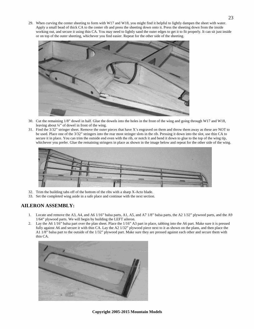
29. When curving the center sheeting to form with W17 and W18, you might find it helpful to lightly dampen the sheet with water. Apply a small bead of thick CA to the center rib and press the sheeting down onto it. Press the sheeting down from the inside working out, and secure it using thin CA. You may need to lightly sand the outer edges to get it to fit properly. It can sit just inside or on top of the outer sheeting, whichever you find easier. Repeat for the other side of the sheeting.
30. Cut the remaining 1/8” dowel in half. Glue the dowels into the holes in the front of the wing and going through W17 and W18,
leaving about ¼” of dowel in front of the wing. 31. Find the 3/32” stringer sheet. Remove the outer pieces that have X’s engraved on them and throw them away as these are NOT to
be used. Place one of the 3/32” stringers into the rear most stringer slots in the rib. Pressing it down into the slot, use thin CA to secure it in place. You can trim the outside end even with the rib, or notch it and bend it down to glue to the top of the wing tip, whichever you prefer. Glue the remaining stringers in place as shown in the image below and repeat for the other side of the wing.
32. Trim the building tabs off of the bottom of the ribs with a sharp X-Acto blade. 33. Set the completed wing aside in a safe place and continue with the next section.
AILERON ASSEMBLY:
1. Locate and remove the A3, A4, and A6 1/16” balsa parts, A1, A5, and A7 1/8” balsa parts, the A2 1/32” plywood parts, and the A9 1/64” plywood parts. We will begin by building the LEFT aileron.
2. Lay the A6 1/16” balsa part over the plan sheet. Place the 1/16” A3 part in place, tabbing into the A6 part. Make sure it is pressed fully against A6 and secure it with thin CA. Lay the A2 1/32” plywood piece next to it as shown on the plans, and then place the A1 1/8” balsa part to the outside of the 1/32” plywood part. Make sure they are pressed against each other and secure them with thin CA.

24
Copyright 2005-2015 Mountain Models
3. Press the A5 1/8” balsa piece into place on the other end of A6 as shown in the image below. Make sure it is fully in place and secure it with thin CA.
4. Dry fit the A9 1/64” plywood piece as shown in the image below. Lightly sand the edges if needed to fit between the end ribs. If it
fits nicely, place a bead of thick CA down the surface and apply it to A6.
5. Press the A4 1/16” balsa part into place as shown below. Secure it with thin CA.
6. Carefully press the A7 1/8” balsa part into place as shown in the image below. Be careful not to damage the part as you are putting
it in place. Make sure it is pressed into place properly with the ribs flush to the outside. The outer bottom of A7 will be aligned with the tabs on A6, and on the bottom, the back edge of A7 will be flush with the bottom of A6. When it is lined up right, secure the joints with thin CA.
7. Repeat steps 2 through 7 for the other aileron,. MAKE SURE you make a LEFT and a RIGHT aileron. Leaving the first one on the
plan sheet will keep you from making 2 of the same side. 8. Set the ailerons aside in a safe place and continue with the next section.

25
Copyright 2005-2015 Mountain Models
FIXED GEAR ASSEMBLY:
1. If you are installing retracts, you can skip this section and proceed to the next step. 2. Bend the 3/32” x 7” wires to the shape shown on the plans. Make your bends as sharp as possible. You can leave a little extra on
the ends and trim them to length after you are finished bending it. (I’m not good at this myself, so try to get them sharper than mine!)
3. Locate and remove the FG3 3/16” balsa and FG4 1/32” plywood parts from their sheets. Apply thick CA to the surface of FG3 and
line up FG4, making sure the holes are aligned. Once again, make sure the holes are aligned! Do this for both sets of parts. Press the parts together while the glue dries to make sure you get a good glue joint here!
4. Locate and remove the FG1 1/16” plywood and 3/32” balsa parts from their sheets. Line up the parts, making sure the slot in FG2
lines up with the lines on FG1. Glue the parts together using thick CA. Press them together while the glue dries to make sure you get a good glue joint here. Do this for both sets of parts.
5. Slide the landing gear through the assembly from the previous step as shown in the image below. Apply thick CA or epoxy to all
inside surfaces that the wire touches and the mating surfaces on the previous 2 assemblies. Press the parts together firmly while the glue is drying to make sure you get a good glue joint. You can also drip glue in from the end of the slot in FG2 to make sure it’s string. Apply a glue fillet to the corner joints between FG1 and FG2. Apply a glue fillet where the wire exits the bottom and top of the gear mount. Do this for both sets of parts.
6. Clean the inside edges of the aluminum tube to make sure that there is a nice clean fit with the landing gear wire.

26
Copyright 2005-2015 Mountain Models
7. Press the aluminum tubes into the wheels. And slide the wheels onto the landing gear wire. 8. Slide the star lock onto the wire to hold the wheel in place. You want a little room for the wheel to move, but not too loose. Secure
the lock in place with a drop of CA. Hit the drop with CA accelerator immediately to keep it from going into the wheel bushing.
9. Set the fixed gear assemblies aside in a safe place and continue to the next section.
SANDING:
1. Lightly sand the fuselage with fine sandpaper. Be careful around the stringers. 2. Lightly sand the wing with fine sandpaper. Make sure to sand W22 at the top center rear to match the ribs to each side of it. That
way the wing fits properly to the fuselage. Be careful when sanding around the stringers. 3. SAND the leading edge of the wing to match the contour of the top and bottom of the ribs. Round off the very leading edge to
finish the airfoil shape. 4. Sand the aileron so the A7 part matches up with the top profile of the ribs and the bottom of A6. 5. On the stab and elevator parts, round all the outside corners. 6. On the vertical fin, round the outside corners. On the Rudder, round the outside corners. Sand the balsa pieces where the control
horn goes through to a nice bevel shape as shown in the image below. Sand a bevel on the rudder as shown in the image below. There is an engraved line down the center to help you sand to the proper place.
RETRACT INSTALLATION:
1. If you are using fixed gear, you can skip this section. 2. Bend the landing gear wires as shown on the plan sheet. Make sure you make a left a right, as the landing gear wires have a flat
ground for the set-screw. MAKE SURE you get the distance from the end that goes into the retract unit to the first bend correct! Leave a little extra on the end that goes through the wheel. You will finish trim it later.
3. Press the included bushings into the wheels. Slide the wheels onto the landing gear wires.
27
Copyright 2005-2015 Mountain Models
4. Cut the yellow plastic tubing to two (2) pieces 3/16” long. Press the tubing onto the retract wire to keep the wheel in place. Secure the plastic in place with a dab of thick CA on the outer end of it. MAKE SURE you do NOT get any glue inside the wheel or on the wire surface where the wheel is.
5. Press the retract landing gear wire into the retract unit and secure it with the set screw include. Make sure the wheels are straight and not angled off to one side. Once you are sure they are straight, drop some thin CA where the wire goes into the body of the retract unit. This will help keep the landing gear wire from twisting and keep it in place.
6. Place your servo as shown in the images below. Mount it using the screws included with your servo. Do not tighten the screws too much. Remove the screws and servo from the wing and drop thin CA into the screw holes to strengthen them. Allow the CA to dry thoroughly and reinstall the servo. There is a hole in W30 for the servo connector to go through.
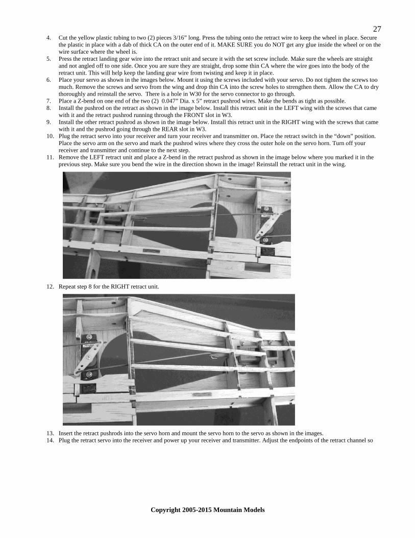
7. Place a Z-bend on one end of the two (2) 0.047” Dia. x 5” retract pushrod wires. Make the bends as tight as possible. 8. Install the pushrod on the retract as shown in the image below. Install this retract unit in the LEFT wing with the screws that came
with it and the retract pushrod running through the FRONT slot in W3. 9. Install the other retract pushrod as shown in the image below. Install this retract unit in the RIGHT wing with the screws that came
with it and the pushrod going through the REAR slot in W3. 10. Plug the retract servo into your receiver and turn your receiver and transmitter on. Place the retract switch in the “down” position.
Place the servo arm on the servo and mark the pushrod wires where they cross the outer hole on the servo horn. Turn off your receiver and transmitter and continue to the next step.
11. Remove the LEFT retract unit and place a Z-bend in the retract pushrod as shown in the image below where you marked it in the previous step. Make sure you bend the wire in the direction shown in the image! Reinstall the retract unit in the wing.
12. Repeat step 8 for the RIGHT retract unit.
13. Insert the retract pushrods into the servo horn and mount the servo horn to the servo as shown in the images. 14. Plug the retract servo into the receiver and power up your receiver and transmitter. Adjust the endpoints of the retract channel so

28
Copyright 2005-2015 Mountain Models
there is no servo chatter in the up or down positions and make sure that the retracts are “locked” in each position. The bends in the wire should be just inside of W3 as shown in the image below. When you are happy with the operation of the retracts, turn off your receiver and transmitter. Don’t forget to install the servo horn screw when you are done.
15. You now have operational retracts! Now go play with them, making electronic swooshing sounds as they go up and down!
COVERING:
1. Glue the vertical fin to the fuselage, making sure it is straight as shown in the image below. You can look through the bottom holding it up to light to see if the fin in right on the center spine of off to one side. You can also use the center joint in the sheeting if you glued the sheeting right on center. You can, if you want, use balsa scraps to fill in the area of the fin in front of V7, or you can use covering only here, more balsa adds more weight, but it’s easier to cover, so it’s up to you.
2. Do NOT over shrink the covering! Cover the wing, ailerons, stabilizer, elevator, and rudder. Follow the instructions that came with your covering if you are new to this. We recommend lightweight covering such as So-Lie or similar.
3. If you are good at covering, you can cover the vertical fin with the same piece as the fuselage side. Else, cover the fin first, stopping the covering at the V7, then the fuselage sides, and then the front of the vertical fin.
4. You can cover the control horns if you would like. Be sure to remove the covering from the section that gets glued in though! 5. If you are using retracts, cover the wing with the gear up and trim the landing gear bays open after covering. Also cover the landing
gear doors.
MORE ASSEMBLY:
1. Bend the 0.047” x 4” tail wheel wire to shape as shown on the plans. Slide the wheel over the wire and secure in place. 2. Look at the plans and find where the tail wheel wire gets mounted. Carefully trim a small notch in the center of the spine so the
wire just pressed in. press the wire through the spine against the former as shown on the plans. Make sure the wire is fully pressed into the groove and secure it with thin CA.
3. Slide the elevator control horn through the RIGHT side slot for the elevator horn. Make sure it is centered and use thin CA to
secure it. 4. Slide the rudder control horn in to the slot in the rudder. Make sure it is centered and use thin CA to secure it. 5. Slide the aileron control horns into the ailerons as shown in the image below. Secure them in place with thin CA.

29
Copyright 2005-2015 Mountain Models
6. Cut the included CA hinge material into pieces as shown below.
7. Slot the vertical fin and rudder for the CA hinges. Do NOT glue them in yet. 8. Slot the stab and elevator for the CA hinges as shown on the plans. Do NOT glue them in yet! 9. Mount the wing onto the fuselage using the included 4-40 nylon bolts. 10. Slide the stabilizer through the slot in the fuselage, right beneath the vertical fin. Make sure it is centered by measuring between the
rear of the wing tip and the front corners of the stabilizer. Make sure this distance is equal. Mark a fine line top and bottom where the stabilizer meets the fuselage/vertical fin. Remove the stabilizer and trim the covering from the center of the stabilizer about 1/8” inside of the lines you scribed.
11. Slide the ELEVATOR into the fuselage slot and slide it to the back of the slot. If it is tight, move it forward and use some sandpaper on the rear inside of the slot until it rotates freely at the back of the slot.
12. With the elevator already through the slot and pushed all the way to the back, slide the stabilizer back into the slot in the fuselage. Make sure it is straight again like in step 2 and wick thin CA into the joints on each side to secure stab to the fuselage. Be careful not to glue the elevator to the fuselage or stabilizer!!!
13. Install the CA hinges in the stab/elevator. After they are all in, secure them with a drop or two of thin CA. Make sure you do not glue the stab and elevator together.
14. Install the CA hinges in the fin/rudder. After they are all in place, secure them with a drop or two of thin CA. Make sure not to glue the fin and rudder together.
15. Hinge the ailerons using light hinge tape or a clear Scotch type tape. You can also do a covering hinge here if you would like. 16. Assemble the landing gear bay doors as shown in the image below. If you are using retracts, line up the doors with the gear in the
UP position. Press down on the bay door where it meets the landing gear wire coming through the wheel. Carefully trim out the balsa where the gear wire left a mark. Find and remove the little square shaped 1/32” balsa pieces. These get mounted to the gear door and landing gear wire as shown in the image below. The easiest way to position them correctly is to place them on the wire, about 1/8” inside of the retract rib, with the solid end facing out. This end gets glued to the bay door. Check the fit with the door and slightly sand material off the end so the gear door sits flush with the wing when the gear are in the UP position. After everything lines up, place some thick CA on the notch for the wire and the end that gets glued to the door, as well as around the end of the landing gear wire. Lay the door down on top of it and allow a bit for glue to dry. Lower the retract gear and reinforce the joints with thick CA fillets. You can now trim the end of the landing gear wire as needed.

30
Copyright 2005-2015 Mountain Models
PLASTICS:
1. For gluing plastic parts together, we suggest using plastic cement. 2. Trim around the outside of the cowling on the flat base close to the edge of the cowling. You want to get close to the cowling but
not into it. Then, lay a sheet of 22- grit sandpaper on your work surface and rub the cowling flat on the sandpaper to sand up to the bottom edge. This makes a nice smooth edge and keeps you from accidentally cutting too far. Cut a small hole in the front center of the cowling, about ¼” Dia. for the shaft, nut, and washer to go through. Carefully trim inside opening for the air intake as this lets a little air in to cool the motor, ESC, and battery.
3. Trim out the exhaust stacks in the same way as the cowling. Glue the exhaust stacks to the cowling. 4. Trim the radiator plastics the same way you did the cowling. Be careful here and take a little off at a time. Like the cowling, you do
not want to cut tight up to or on the side walls. Use sandpaper in the same way as the cowling to get nice flat surfaces. Glue the halves of the radiator scoop together. Make sure you get a good bond. Trim the round recesses in the radiator out to fit the plastic straw. Glue in the straw and trim it flush with the top and bottom surfaces of the radiator. After it has dried, mount the wing to the fuselage. Glue the radiator to the bottom of the wing, using the holes in the radiator and screws holding the wing in place as a guide.
5. Trim and glue the seat parts together in the same way as the radiator scoop. 6. Trim the cockpit as shown in the image below. You want the front and back of the cockpit sitting just between the formers on the
canopy frame (Do NOT glue it to the frame yet.) 7. Trim the very ends off the canopy. Do not trim too far inward! Set the canopy frame in the fuselage and the canopy over the canopy
frame. Carefully mark the front and back of the canopy where it needs to be trimmed to fit the frame. (Just inside the opening in the fuselage) You should hold off on trimming the sides until later. Trim the canopy a little at a time until the fron and back fit properly.
8. Glue the plastic seat from step 5 into the cockpit, using the slots as a guide. 9. Paint the cockpit with as much detail as you would like. 10. Clean the inside of the canopy of any fingerprints or dust. Use an X-acto or light sandpaper to remove any paint from the cockpit
where it comes in contact with the canopy so you can get a good glue bond. Glue the cockpit into the canopy, making sure it is centered and lined up front to rear. The cockpit will sit back from the front and rear edges of the canopy slightly to clear the canopy frame formers.
11. Place some plastic wrap or wax paper in the cutout of the fuselage where the canopy section goes. This will keep you from accidentally gluing the canopy frame to the fuselage. Set the canopy frame in place on the fuselage. Apply glue to the cockpit frame formers and sides. Lay the plastic canopy down over it and hold it against the balsa until the glue sets.
12. After the glue has set, remove the canopy from the fuselage and trim the sides/bottom of the canopy to fit flush with the bottom of the canopy frame.
13. Clean the plastic parts to remove any mold release or fingerprints and lightly sand with 600 grit sandpaper. Paint the plastics using
your chosen colors. Be light in the application of paint, as weight can add up quickly!

31
Copyright 2005-2015 Mountain Models
ELECTRONICS:
1. Push the motor/gearbox assembly onto the motor stick as far back as it will go. Secure the gearbox to the stick using a small screw through the top. Drilling a hole with an undersized bit for the screw will help keep the plastic or plywood mount from splitting.
2. Push the motor stick through the holes in F1 and F2. The back of the motor stick should just be sticking through the back of F2, about 1/16” or so. Do NOT glue it in yet. Place the cowling on the front and then your pro/spinner. Pull/push the motor stick forward and aft until the spinner has about 1/16” clearance with the cowling. When you have it in place, use some thin CA to secure the stick in place at the back of F2. Remove the prop/spinner and cowling and finish securing the motor stick to F1 and F2. Place a fillet of thick CA around the joint between the motor stick and F1.
3. Hook up your ESC to your motor and push it and the wires through the opening in F1.
4. Turn the fuselage upside down and install the servo mounts in the fuselage as shown in the image below. The position in the image is where we have mounted ours, but there is some room to move them forward, depending on the equipment you choose. Glue in the rear servo mount first using thin CA. Use a servo to position the front servo mount and glue it in place using thin CA.
5. Mount your servos as shown, using the mounting screws that came with your servos. After they LIGHTLY screwed in, remove the
screws and servos. Reinforce the screw holes in the balsa with thin CA. After this has dried COMPLETELY, reinstall your servos with the screws.
6. Install the Micro servo connectors on the servo arms and press the servo arms onto the servos. 7. Using a sharp X-Acto blade, create slits in the fuselage for the pull-pull thread to go through as shown on the plans. 8. When rigging the pull-pull lines, be careful not to “wrap” other lines as this can cause a not so smooth operation of the control
surfaces. 9. Tie one end of the pull-pull thread to a cotter pin. Press the cotter pin through the bottom elevator slit and run the cotter pin back to
the servo connector. Push the cotter pin about half way through and lightly tighten the screw. Cut the pull-pull thread about 2” past the control horn.
10. Repeat step 8 for the other side of the elevator control horn. 11. Holding the elevator in neutral position, tie the loose end of the pull-pull thread to the control horn, getting the line as tight as you
can while keeping the elevator at neutral. Repeat for the other side of the control horn. 12. Adjust the pull-pull cables at the servo arm as needed to get tight lines on both sides when the elevator is neutral 13. Repeat steps 9 through 11 for the rudder control horn and servo. 14. Turn on your radio and make sure the servo horn and horns are centered. Secure the horns with the servo horn screws. 15. Glue the battery mount in place at this time. Using thick CA. 16. Apply one side of the adhesive backed Velcro the battery mount. 17. Cut off enough of the other side of the adhesive backed Velcro and apply it to the back of your receiver. The Velcro that is left is
for your battery. The receiver will be mounted on the front section of the battery mount. 18. Cut out the slot in the top of the wing (W31) for the servo wires to come through. Run a piece of thread down the hole, through the
wing, and out the servo mount hole in the wing. Do this for both sides. Tie the thread to your servo wires and pull them through the wing. Install the aileron servos in the wings with the servo arm to the back of the wing. Remove the screws and drop thin CA into the holes to strengthen them. After the CA has thoroughly dried, reinstall the servos and screws. Install a mini servo connector on each servo arm.

32
Copyright 2005-2015 Mountain Models
19. Put a Z-Bend on the end of the 0.047” Dia. X 4” aileron pushrods. Slide the z-bend through the hole in the aileron control horn.
Slide the servo connector on one of the servo arms onto the aileron pushrod and press the horn into place on the servo. Repeat for the other aileron. You want to have a slight offset of the servo horn for the ailerons to get differential throw from the ailerons. (if you do not have differential throws on your Tx) See the picture below for an approximate offset angle. After placing the servo arms on the servo at the correct angles, set the ailerons at neutral and tighten the screw on the servo connector.
20. Go through the instructions again and make sure you didn’t miss anything. Make sure your control surfaces are moving in the right
direction and that the retracts operate without servo chatter in the up or down position. 21. Install your radio gear and flight battery and balance the model ¼” in front of the spar cap for your first flight. You can shift it
forward or aft to suit your flying style and preferences.
CONTROL SURFACE THROWS:
1. Ailerons should be 5/8” UP and 3/8” DOWN 2. Elevator should be 5/8” UP and DOWN 3. Rudder should be 3/4” LEFT and RIGHT
YOUR FIRST FLIGHT:
1. Take pictures first! It’s as pretty as it’s ever going to be, so get plenty of good pictures to show off your model on R/C Groups or other online forums.
2. Wait for a nice calm day for your first flight. This will give you the best time to get familiar with the model and how it flies. 3. During your first flight, after you have trimmed the controls, gain some altitude and slow the model down to see where the stall is
and what happens when it stalls. You should be aware of the stall speed on landing so you don’t slow it down too much. 4. Keep a little power on landing until you are familiar with the model. 5. GOOD LUCK! Let me know what you think of the model by emailing us at [email protected]

33
Copyright 2005-2015 Mountain Models