Embed Size (px)
Citation preview

Learning for VMM + WTA Embedded Classifiers
Jennifer Hasler and Sahil Shah Electrical and Computer Engineering
Georgia Institute of Technology, Atlanta, GA, USA
Abstract: The authors present training and feedforward computation for a single layer of a VMM+WTA classifier. The experimental demonstration of the one-layer universal approximator encourages the use of one-layer networks for embedded low-power classification. The results enabling correct classification of each novel acoustic signal (generator, idle car, and idle truck). The classification structure requires, after training, less than 30μW of operational power and lower with additional fabrication.
Keywords: Embedded Machine Learning ICs, Neuromorphic Engineering; FPAAs; Floating-Gate
This paper focuses on training of classifiers for a single layer of a Vector-Matrix Multiplier (VMM) and a single layer of a k-Winner-Take-All (WTA), built on our original foundational work on VMM + WTA classifiers being demonstrated experimentally as a universal approximator [1], and recent work demonstrating a single engineer-tuned example of wordspotting classification in a recent large-scale Field Programmable Analog Array (FPAA) [2,3]. The experimental demonstration of the one-layer universal approximation concept [1], encourages the use of one-layer (or multiple layer) networks for embedded low-power classification. A universal approximator classifier represents any static function (with infinite resources).
Foundations of VMM+WTA Learning
The fundamental question is enabling a working supervised learning technique for these systems, something not explicitly achieved in previous hardware or software systems, but is achieved through this work in hardware (experimentally) and software by understanding the connections of these networks to Self Organizing Maps (SOM), Vector Quantitization (VQ), and Gaussian Mixture Models (GMM). Training multilayer networks, required for universal approximation outside of this approach, often has issues with training due to error estimations in all but the last layer of classification; avoiding this issue is central in most neural network and deep learning theory. A fundamental aspect to developing the VMM+WTA classifier block is developing a mathematical framework to analyze the network capability. We find that a VMM+WTA classifier block is equivalent to, among other networks, VQ, and with some extensions, to a GMM network; this connection leads to developing an on-chip, universal approximator learning algorithm on an SoC FPAA.
Classifier Data Set: Sound Classification
Classification focuses on identifying one of multiple acoustic sounds as our representative, although not exhaustive, example, for a system both macro modeled in MATLAB as well as built and measured on our SoC FPAA IC. The test input is composed of signals from urban environment for 3 objects (generator, idle car, and idle truck) randomly turning on for 1-2 seconds in a background ”quiet” sound setting a typical background noise; the process constructs a challenging labeled data set. The dataset is derived from urban and rural datasets distributed by DARPA as part of the NZero project.
AVLSI Computation of Classifier Data Set
The datasets are processed through a using a constant Q filterbank (from 1.6Hz to 5KHz), amplitude detection, and LPF (5Hz) structure consistent with our Simulink modeling for experimental FPAA modeling. The input acoustic signal, going through a typical input ac coupling, was converted from pressure as 40mV / Pascal, similar to the front-end sensors in the testbed measurement (which include high-pass corner frequencies around 20Hz). Figure 2 shows the output signals from the bandpass filter block for generator datasets in rural (dirt) conditions, showing the strong narrow response just under 100Hz. Figure 2 shows the resulting output amplitudes and background noise level (from quiet set) showing different resulting spectrums from
Fig. 1: Block diagram for the Vector-Matrix Multiplier (VMM) with dynamic k-Winner-Take-All (WTA) Embedded Classifier, including the front- end circuitry, VMM (from x(t) → z (t), and k-WTA (from z(t) → y(t) ) blocks. In this case, we model the front-end circuitry for an auditory application as constant Q filters, amplitude detection, and post filtering for the desired temporal response for classification.
479Distribution A: Approved for public release; distribution unlimited.

the three cases. Our classifier uses a number of nulls in the space highly reducing the number of false alarm cases, as well as enabling typical GMM type operation.
FPAA VMM+WTA Classifier Operation
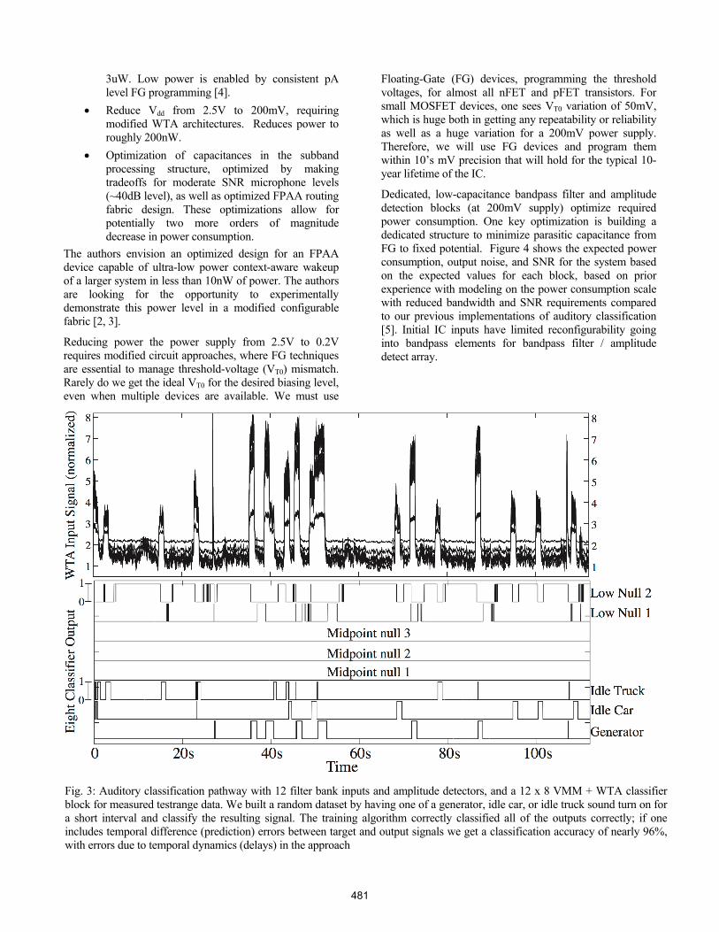
We implemented the first supervised VMM+WTA training algorithm, implemented both in MATLAB and on the SoC FPAA IC to converge to a weight set for a 12input, 8output VMM+WTA block trained on learning to identify the three different mechanical systems being activated along with 5 nulls symbols in the resulting space. The training algorithm requires moving the adaptation computation on-chip, including partially using the on-chip μP (fixed point computation) and Floating-Gate (FG) programming infrastructure (14bit ≈ log encoding). Figure 3 shows the
results of this algorithm, enabling correct classification of each novel acoustic signal. The classification structure requires, after training, less than 30μW of power for the resulting classification. We also have a roadmap on how to scale this FPAA design to reduce the resulting power dissipation multiples orders of magnitude less (say 10nW) with another IC fabrication in this IC process.
Decrease of FPAA, VMM+WTA Classifier Power
The previous section resulted in roughly 30uW power consumption; this section analyzes how to reach nW power consumption. Three key analysis directions show
Optimize power for the current FPAA device, both in routing capacitance and bias current past C4 filter stage, improving power consumed to
Fig. 2. Analysis for the FPAA IC classifier with acoustic field test data developed by DARPA for acoustic classification in both for rural and urban condition datasets. We summarize the experimental conditions for the acoustic measurements for both the rural (dirt) as well as urban (concrete) situations. We are showing sample curves from the datasets we analyzed using circuit modeled MATLAB data set (similar to what is used in our Scilab design tools), including filterbank output from the rural generator, as well as input classifier results from a rural truck data set, an urban generator set, and urban idle car dataset. Solid lines represent our extracted background levels obtained from quiet datasets provided, showing significant signals for classification as well as a sense of how to pattern signals for training and recognition. The generator seems to have very strong signals just below 100Hz with significant signals around it. For the idle car data, we see far more higher frequency signals to distinguish its behavior. For rural signals, we see a stronger single peak frequency (or small group of frequencies) due to the higher attenuation through a dirt (rather than concrete) environment.
480
3uW. Low power is enabled by consistent pA level FG programming [4].
Reduce Vdd from 2.5V to 200mV, requiring modified WTA architectures. Reduces power to roughly 200nW.
Optimization of capacitances in the subband processing structure, optimized by making tradeoffs for moderate SNR microphone levels (~40dB level), as well as optimized FPAA routing fabric design. These optimizations allow for potentially two more orders of magnitude decrease in power consumption.
The authors envision an optimized design for an FPAA device capable of ultra-low power context-aware wakeup of a larger system in less than 10nW of power. The authors are looking for the opportunity to experimentally demonstrate this power level in a modified configurable fabric [2, 3].
Reducing power the power supply from 2.5V to 0.2V requires modified circuit approaches, where FG techniques are essential to manage threshold-voltage (VT0) mismatch. Rarely do we get the ideal VT0 for the desired biasing level, even when multiple devices are available. We must use
Floating-Gate (FG) devices, programming the threshold voltages, for almost all nFET and pFET transistors. For small MOSFET devices, one sees VT0 variation of 50mV, which is huge both in getting any repeatability or reliability as well as a huge variation for a 200mV power supply. Therefore, we will use FG devices and program them within 10’s mV precision that will hold for the typical 10-year lifetime of the IC.
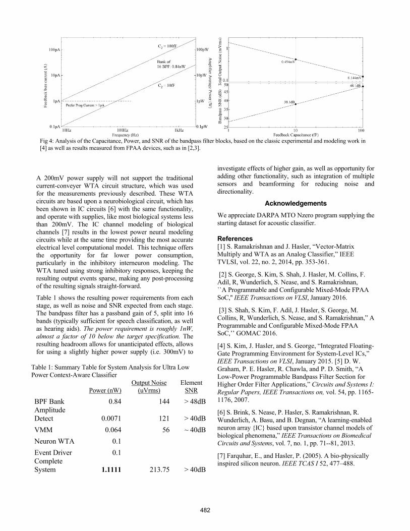
Dedicated, low-capacitance bandpass filter and amplitude detection blocks (at 200mV supply) optimize required power consumption. One key optimization is building a dedicated structure to minimize parasitic capacitance from FG to fixed potential. Figure 4 shows the expected power consumption, output noise, and SNR for the system based on the expected values for each block, based on prior experience with modeling on the power consumption scale with reduced bandwidth and SNR requirements compared to our previous implementations of auditory classification [5]. Initial IC inputs have limited reconfigurability going into bandpass elements for bandpass filter / amplitude detect array.
Fig. 3: Auditory classification pathway with 12 filter bank inputs and amplitude detectors, and a 12 x 8 VMM + WTA classifier block for measured testrange data. We built a random dataset by having one of a generator, idle car, or idle truck sound turn on for a short interval and classify the resulting signal. The training algorithm correctly classified all of the outputs correctly; if one includes temporal difference (prediction) errors between target and output signals we get a classification accuracy of nearly 96%, with errors due to temporal dynamics (delays) in the approach
481
A 200mV power supply will not support the traditional current-conveyer WTA circuit structure, which was used for the measurements previously described. These WTA circuits are based upon a neurobiological circuit, which has been shown in IC circuits [6] with the same functionality, and operate with supplies, like most biological systems less than 200mV. The IC channel modeling of biological channels [7] results in the lowest power neural modeling circuits while at the same time providing the most accurate electrical level computational model. This technique offers the opportunity for far lower power consumption, particularly in the inhibitory interneuron modeling. The WTA tuned using strong inhibitory responses, keeping the resulting output events sparse, making any post-processing of the resulting signals straight-forward.
Table 1 shows the resulting power requirements from each stage, as well as noise and SNR expected from each stage. The bandpass filter has a passband gain of 5, split into 16 bands (typically sufficient for speech classification, as well as hearing aids). The power requirement is roughly 1nW, almost a factor of 10 below the target specification. The resulting headroom allows for unanticipated effects, allows for using a slightly higher power supply (i.e. 300mV) to
investigate effects of higher gain, as well as opportunity for adding other functionality, such as integration of multiple sensors and beamforming for reducing noise and directionality.
Acknowledgements
We appreciate DARPA MTO Nzero program supplying the starting dataset for acoustic classifier.
References [1] S. Ramakrishnan and J. Hasler, “Vector-Matrix Multiply and WTA as an Analog Classifier,” IEEE TVLSI, vol. 22, no. 2, 2014, pp. 353-361.
[2] S. George, S. Kim, S. Shah, J. Hasler, M. Collins, F. Adil, R, Wunderlich, S. Nease, and S. Ramakrishnan, ``A Programmable and Configurable Mixed-Mode FPAA SoC,'' IEEE Transactions on VLSI, January 2016.
[3] S. Shah, S. Kim, F. Adil, J. Hasler, S. George, M. Collins, R, Wunderlich, S. Nease, and S. Ramakrishnan,” A Programmable and Configurable Mixed-Mode FPAA SoC,’’ GOMAC 2016.
[4] S. Kim, J. Hasler, and S. George, “Integrated Floating-Gate Programming Environment for System-Level ICs,” IEEE Transactions on VLSI, January 2015. [5] D. W. Graham, P. E. Hasler, R. Chawla, and P. D. Smith, “A Low-Power Programmable Bandpass Filter Section for Higher Order Filter Applications,” Circuits and Systems I: Regular Papers, IEEE Transactions on, vol. 54, pp. 1165-1176, 2007.
[6] S. Brink, S. Nease, P. Hasler, S. Ramakrishnan, R. Wunderlich, A. Basu, and B. Degnan, “A learning-enabled neuron array {IC} based upon transistor channel models of biological phenomena,” IEEE Transactions on Biomedical Circuits and Systems, vol. 7, no. 1, pp. 71--81, 2013.
[7] Farquhar, E., and Hasler, P. (2005). A bio-physically inspired silicon neuron. IEEE TCAS I 52, 477–488.
Table 1: Summary Table for System Analysis for Ultra Low Power Context-Aware Classifier
Power (nW) Output Noise
(uVrms) Element
SNR
BPF Bank 0.84 144 > 48dB Amplitude Detect 0.0071 121 > 40dB
VMM 0.064 56 ~ 40dB
Neuron WTA 0.1
Event Driver 0.1 Complete System 1.1111 213.75 > 40dB
Fig 4: Analysis of the Capacitance, Power, and SNR of the bandpass filter blocks, based on the classic experimental and modeling work in [4] as well as results measured from FPAA devices, such as in [2,3].
482