Embed Size (px)
Citation preview


M A K I N G V I R T U A L R E A L I T Y
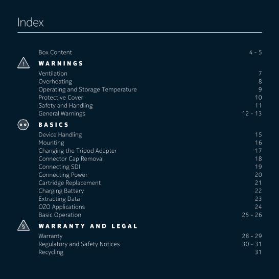
Index
Box Content 4 - 5
W A R N I N G S Ventilation 7Overheating 8Operating and Storage Temperature 9Protective Cover 10Safety and Handling 11General Warnings 12 - 13
B A S I C S Device Handling 15Mounting 16Changing the Tripod Adapter 17Connector Cap Removal 18Connecting SDI 19Connecting Power 20Cartridge Replacement 21Charging Battery 22Extracting Data 23OZO Applications 24Basic Operation 25 - 26
W A R R A N T Y A N D L E G A L Warranty 28 - 29Regulatory and Safety Notices 30 - 31Recycling 31
Box Content
11 12
10
8
2
1
4
9
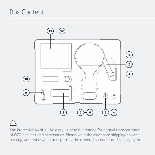
The Protective NANUK 950 carrying case is intended for normal transportation of OZO and included accessories. Please keep the cardboard shipping box and packing, and reuse when transporting the camera by courier or shipping agent.
7 6
3
5
1. ProtectiveCover(comesfittedtocamera)
2. Largetripodadapter(comesfittedtocamera)
3. OZO Professional VR Camera PC-01
4. 3G-SDI adapter card in protective ESD bag, for external recording/monitoring
5. T6 tool, for removing Connector Cap of power/SDI slot
6. Digital Cartridge DC-01, including 33Wh Li-Ion rechargeable battery
7. Media Module MM-01, including 500GB solid state storage
8. Docking Station DS-01, for battery charging and data transfer
9. Media Cable MC-01, for USB3 data transfer to computer directly from Media Module or cartridge in Docking Station.
10. Small tripod adapter
11. Camera External AC power supply and AC cables
12. Docking Station AC power supply and AC cables
NOTE:DuetothesizethecaseshouldtravelasholdluggagewhenflyingwithOZObutthecartridges(containingLi-Ionbatteries)shouldberemovedandcarried as hand luggage according to international regulations.
5
W A R N I N G S
Ventilation
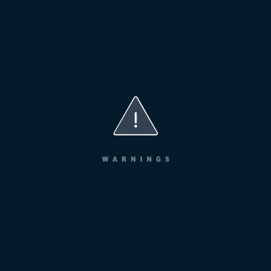
Do not cover the ventilation opening (A).
TheDeviceiscooledbyairflowingbetween the outer and inner structure.
Keep the device ventilation upright (B).
Covering the opening or mounting the device in a way that the openings are not vertically on top of each other would prevent the air fromflowing.
7
B
A
Overheating
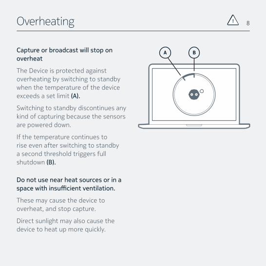
Capture or broadcast will stop on overheat
The Device is protected against overheating by switching to standby when the temperature of the device exceeds a set limit (A).
Switching to standby discontinues any kind of capturing because the sensors are powered down.
If the temperature continues to rise even after switching to standby a second threshold triggers full shutdown (B).
Do not use near heat sources or in a space with insufficient ventilation.
These may cause the device to overheat, and stop capture.
Direct sunlight may also cause the device to heat up more quickly.
8
BA
Operating and Storage Temperature
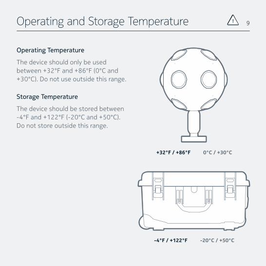
Operating Temperature
The device should only be used between +32°F and +86°F (0°C and +30°C).Donotuseoutsidethisrange.
Storage Temperature
The device should be stored between -4°Fand+122°F(-20°Cand+50°C).Do not store outside this range.
9
+32°F / +86°F 0°C / +30°C
-4°F / +122°F -20°C / +50°C
Protective Cover
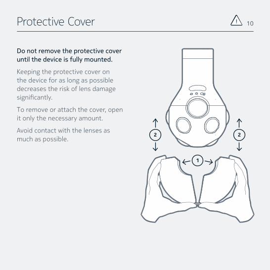
Do not remove the protective cover until the device is fully mounted.
Keeping the protective cover on the device for as long as possible decreases the risk of lens damage significantly.
To remove or attach the cover, open it only the necessary amount.
Avoid contact with the lenses as much as possible.
1
10
2 2
Safety and Handling
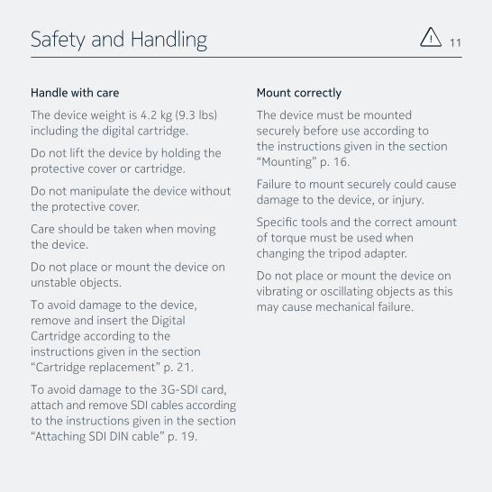
Handle with care
Thedeviceweightis4.2kg(9.3lbs)including the digital cartridge.
Do not lift the device by holding the protective cover or cartridge.
Do not manipulate the device without the protective cover.
Care should be taken when moving the device.
Do not place or mount the device on unstable objects.
To avoid damage to the device, remove and insert the Digital Cartridge according to the instructions given in the section “Cartridge replacement” p. 21.
To avoid damage to the 3G-SDI card, attach and remove SDI cables according to the instructions given in the section “Attaching SDI DIN cable” p. 19.
Mount correctly
The device must be mounted securely before use according to the instructions given in the section “Mounting” p. 16.
Failure to mount securely could cause damage to the device, or injury.
Specifictoolsandthecorrectamountof torque must be used when changing the tripod adapter.
Do not place or mount the device on vibrating or oscillating objects as this may cause mechanical failure.
11
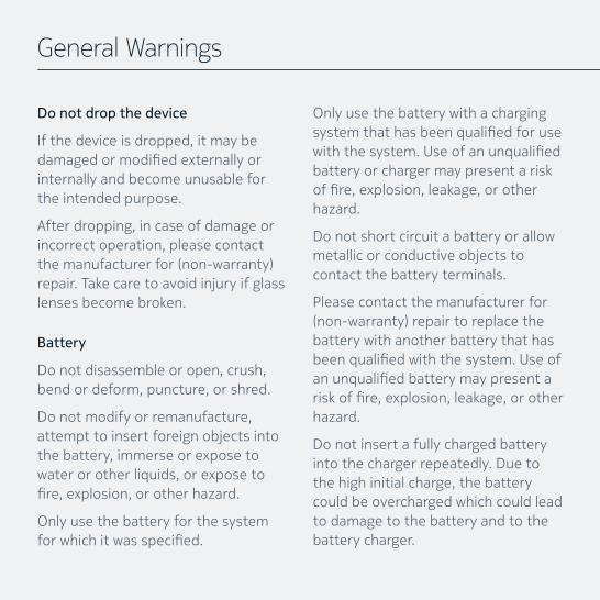
General Warnings
Do not drop the device
If the device is dropped, it may be damagedormodifiedexternallyorinternally and become unusable for the intended purpose.
After dropping, in case of damage or incorrect operation, please contact themanufacturerfor(non-warranty)repair. Take care to avoid injury if glass lenses become broken.
Battery
Do not disassemble or open, crush, bend or deform, puncture, or shred.
Do not modify or remanufacture, attempt to insert foreign objects into the battery, immerse or expose to water or other liquids, or expose to fire,explosion,orotherhazard.
Only use the battery for the system forwhichitwasspecified.
Only use the battery with a charging systemthathasbeenqualifiedforusewiththesystem.Useofanunqualifiedbattery or charger may present a risk offire,explosion,leakage,orotherhazard.
Do not short circuit a battery or allow metallic or conductive objects to contact the battery terminals.
Please contact the manufacturer for (non-warranty)repairtoreplacethebattery with another battery that has beenqualifiedwiththesystem.Useofanunqualifiedbatterymaypresentariskoffire,explosion,leakage,orotherhazard.
Do not insert a fully charged battery into the charger repeatedly. Due to the high initial charge, the battery could be overcharged which could lead to damage to the battery and to the battery charger.
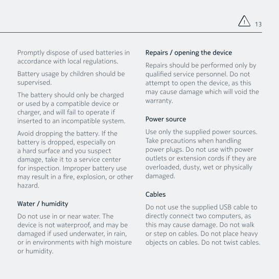
Promptly dispose of used batteries in accordance with local regulations.
Battery usage by children should be supervised.
The battery should only be charged or used by a compatible device or charger, and will fail to operate if inserted to an incompatible system.
Avoid dropping the battery. If the battery is dropped, especially on a hard surface and you suspect damage, take it to a service center for inspection. Improper battery use mayresultinafire,explosion,orotherhazard.
Water / humidity
Do not use in or near water. The device is not waterproof, and may be damaged if used underwater, in rain, or in environments with high moisture or humidity.
Repairs / opening the device
Repairs should be performed only by qualifiedservicepersonnel.Donotattempt to open the device, as this may cause damage which will void the warranty.
Power source
Use only the supplied power sources. Take precautions when handling power plugs. Do not use with power outlets or extension cords if they are overloaded, dusty, wet or physically damaged.
Cables
Do not use the supplied USB cable to directly connect two computers, as this may cause damage. Do not walk or step on cables. Do not place heavy objects on cables. Do not twist cables.
13

B A S I C S

Device Handling
This is the most reliable way of handling the device.
Lift the device at the “tail” applying afirmandsafegrip.
Additionally you can hold the device by the OZO Tripod adapter if it is properly attached.
15
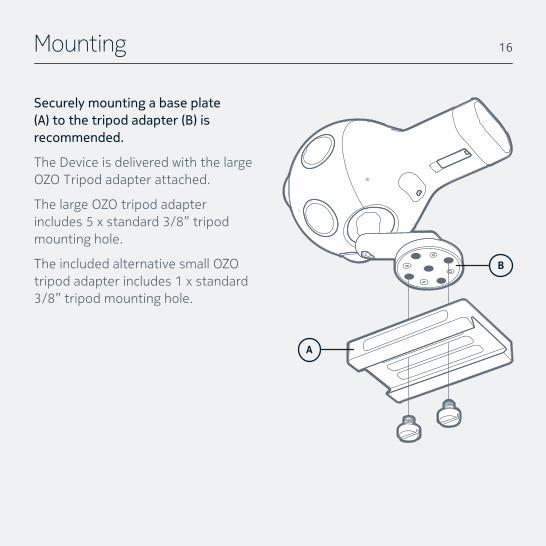
Mounting
Securely mounting a base plate (A) to the tripod adapter (B) is recommended.
The Device is delivered with the large OZO Tripod adapter attached.
The large OZO tripod adapter includes 5 x standard 3/8” tripod mounting hole.
The included alternative small OZO tripod adapter includes 1 x standard 3/8” tripod mounting hole.
B
A
16
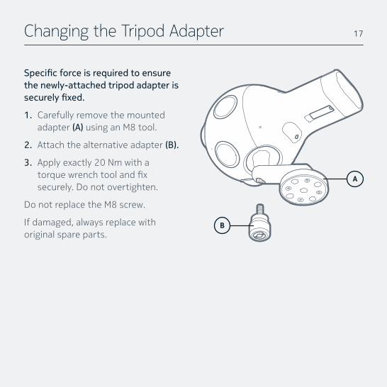
Changing the Tripod Adapter
Specific force is required to ensure the newly-attached tripod adapter is securely fixed.
1. Carefully remove the mounted adapter (A) using an M8 tool.
2. Attach the alternative adapter (B).
3. Apply exactly 20 Nm with a torquewrenchtoolandfixsecurely. Do not overtighten.
Do not replace the M8 screw.
If damaged, always replace with original spare parts.
17
A
B
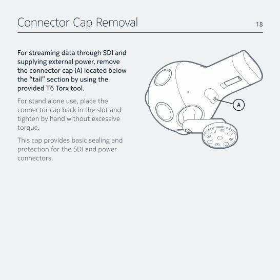
Connector Cap Removal
For streaming data through SDI and supplying external power, remove the connector cap (A) located below the “tail” section by using the provided T6 Torx tool.
For stand alone use, place the connector cap back in the slot and tighten by hand without excessive torque.
This cap provides basic sealing and protection for the SDI and power connectors.
18
A
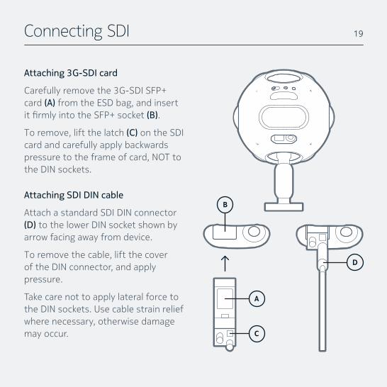
Connecting SDI
Attaching 3G-SDI card
Carefully remove the 3G-SDI SFP+ card (A) from the ESD bag, and insert itfirmlyintotheSFP+socket(B).
To remove, lift the latch (C) on the SDI card and carefully apply backwards pressure to the frame of card, NOT to the DIN sockets.
Attaching SDI DIN cable
Attach a standard SDI DIN connector (D) to the lower DIN socket shown by arrow facing away from device.
To remove the cable, lift the cover of the DIN connector, and apply pressure.
Take care not to apply lateral force to the DIN sockets. Use cable strain relief where necessary, otherwise damage may occur.
19
B
C
A
D
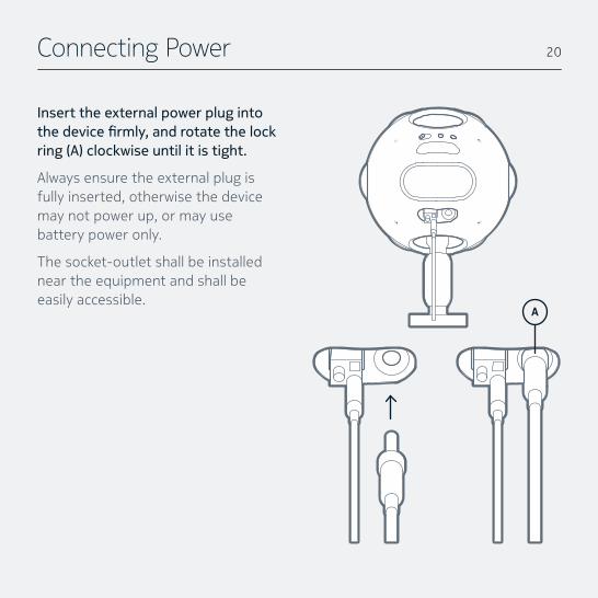
Connecting Power
Insert the external power plug into the device firmly, and rotate the lock ring (A) clockwise until it is tight.
Always ensure the external plug is fully inserted, otherwise the device may not power up, or may use battery power only.
The socket-outlet shall be installed near the equipment and shall be easily accessible.
20
A
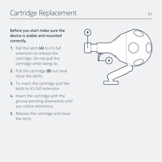
Cartridge Replacement
Before you start make sure the device is stable and mounted correctly.
1. Pull the latch (A) to it’s full extension to release the cartridge. Do not pull the cartridge while doing so.
2. Pull the cartridge (B) out (and closethelatch).
3. To insert the cartridge pull the latch to it’s full extension.
4. Insert the cartridge with the groove pointing downwards until you notice resistance.
5. Release the cartridge and close the latch.
B
21
A
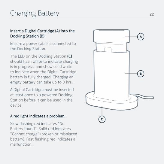
Charging Battery
Insert a Digital Cartridge (A) into the Docking Station (B).
Ensure a power cable is connected to the Docking Station.
The LED on the Docking Station (C) shouldflashwhitetoindicatechargingis in progress, and show solid white to indicate when the Digital Cartridge battery is fully charged. Charging an empty battery can take up to 3 hrs.
A Digital Cartridge must be inserted at least once to a powered Docking Station before it can be used in the device.
A red light indicates a problem.
Slowflashingredindicates“NoBattery found”. Solid red indicates “Cannot charge” (broken or misplaced battery).Fastflashingredindicatesamalfunction.
22
C
B
A
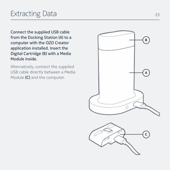
Extracting Data
Connect the supplied USB cable from the Docking Station (A) to a computer with the OZO Creator application installed. Insert the Digital Cartridge (B) with a Media Module inside.
Alternatively, connect the supplied USB cable directly between a Media Module (C) and the computer.
23
C
A
B
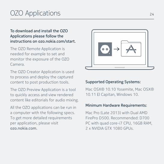
OZO Applications
To download and install the OZO Applications please follow the instructions on ozo.nokia.com/start.
The OZO Remote Application is needed for example to set and monitor the exposure of the OZO Camera.
The OZO Creator Application is used to process and deploy the captured content to post production tools.
The OZO Preview Application is a tool to quickly access and view rendered content like editorials for audio mixing.
All the OZO applications can be run in a computer with the following specs. To get more detailed requirements per application, please visit ozo.nokia.com.
24
Supported Operating Systems:
Mac OSX® 10.10 Yosemite, Mac OSX® 10.11 El Capitan, Windows 10.
Minimum Hardware Requirements:
MacPro(Late2013)withDualAMDFirePro D500. Recommended: D700 PC with quad core-i7 CPU, 16GB RAM, 2 x NVIDIA GTX 1080 GPUs.
Basic Operation
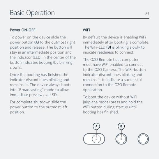
Power ON-OFF
To power on the device slide the power button (A) to the outmost right position and release. The button will stay in an intermediate position and theindicator(LED)inthecenterofthebutton indicates booting (by blinking slowly).
Oncethebootinghasfinishedtheindicator discontinues blinking and remains lit. The device always boots into “Broadcasting” mode to allow immediate preview over SDI.
For complete shutdown slide the power button to the outmost left position.
WiFi
By default the device is enabling WiFi immediately after booting is complete. The WiFi-LED (B) is blinking slowly to indicate readiness to connect.
The OZO Remote host computer must have WiFi enabled to connect to the OZO Camera. The WiFi-button indicator discontinues blinking and remains lit to indicate a successful connection to the OZO Remote Application.
To boot the device without WiFi (airplanemode)pressandholdtheWiFi button during startup until bootinghasfinished.
A B
25
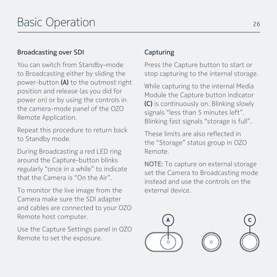
Broadcasting over SDI
You can switch from Standby-mode to Broadcasting either by sliding the power-button (A) to the outmost right position and release (as you did for poweron)orbyusingthecontrolsinthe camera-mode panel of the OZO Remote Application.
Repeat this procedure to return back to Standby mode.
During Broadcasting a red LED ring around the Capture-button blinks regularly “once in a while” to indicate that the Camera is “On the Air”.
To monitor the live image from the Camera make sure the SDI adapter and cables are connected to your OZO Remote host computer.
Use the Capture Settings panel in OZO Remote to set the exposure.
Capturing
Press the Capture button to start or stop capturing to the internal storage.
While capturing to the internal Media Module the Capture button indicator (C) is continuously on. Blinking slowly signals “less than 5 minutes left”. Blinking fast signals “storage is full”.
Theselimitsarealsoreflectedinthe “Storage” status group in OZO Remote.
NOTE: To capture on external storage set the Camera to Broadcasting mode instead and use the controls on the external device.
Basic Operation 26
A C

W A R R A N T Y A N D L E G A L
WARRANTY, WARRANTY LIMITATIONS AND WARRANTY DISCLAIMER
Subject to the limitations and disclaimers set forth below, Nokia warrants that the products shall be of good quality and free from defects in material and workmanship. Upon the expiration of the time periods set forth below, all liabilities of Nokia will terminate.
Standard Product Warranty
A standard product warranty is granted to the originalBuyerbyNokiaforaperiodofone(1)year,parts and labor, for the camera, excluding the bat-teries.(“StandardProductWarranty”)Thestandardwarrantyforbatteriesisninety(90)daysfromthedate of delivery of the products to Buyer. This Standard Product Warranty covers parts and labor charges for products that have been returned pre-paid shipment to Nokia, a Nokia Reseller or Nokia authorized service center, as directed by Nokia. All warranty returns shall be done in accordance withNokia’sreturnmaterialsauthorization(“RMA”)process. Any repaired or replaced product shall be warrantedforaperiodthegreaterof(i)thebalanceof the applicable warranty period relating to such Productor(ii)ninety(90)daysafteritisreceivedby Buyer. Only the components that were repaired or replaced will be eligible for the 90-day period as set forth above. The Standard Product Warranty effectivedateisthedatetheproductwasreceivedby Buyer or Reseller (if purchased for Reseller’s own use).
Product Warranty Limitations
All Nokia warranties exclude the following:
1. Maintenance, repair or replacement necessi-tated by loss or damage resulting from any cause other than normal use and operation of the product in accordance with the Nokia’s specificationsandproductmanual,includingbut not limited to: theft, exposure to weather conditions, use of the product underwater or in wet environments, operator negligence, mis-use, abuse, improper electrical/power supply;
2. Alterations,modificationsorrepairsbyBuyeror unauthorized third parties;
3. Accident, disaster, improper handling or storage,droppage,modificationtothecamera,opening the camera body, use third party accessories or acts of nature or any other peril originating from outside the product;
4. Transportation damage (except for transpor-tation damaged in delivery of the products toBuyerfromNokia),lackofmaintenance,defective batteries, battery leakage;
5. Cosmetic damage or other non-operating parts;
6. Using a product in a manner other than intend-ed usage for that product; and
7. Charges related to “No Trouble Found” diagno-sis.
Warranty
Voiding of Product Warranty
Removalormodificationofcameramountsvoidsany and all warranties. Breaking the seal on the camera body is prohibited and voids any and all warranties unless otherwise approved in writing by Nokia. Any parts replaced by Nokia during warranty repair are the property of Nokia and will not be returned to Buyer. Nokia may use refurbished parts for repairs or replacements. Nokia products are compatible with Nokia software, Nokia parts, and Nokia products only. Use of any software, parts, or products other than Nokia or Nokia-approved software, parts, and products voids any and all warranties.
Warranty Disclaimer
EXCEPT AS SPECIFICALLY SET FORTH ABOVE, NOKIA AND ITS LICENSORS MAKE NO WARRANTIES, CON-DITIONS, REPRESENTATION OR TERMS, EXPRESS OR IMPLIED, WHETHER BY STATUTE, COMMON LAW, CUSTOM, USAGE OR OTHERWISE AS TO THE PRODUCT OR ANY COMPONENT THEREOF, INCLUD-ING BUT NOT LIMITED TO NON-INFRINGEMENT OF THIRD PARTY RIGHTS, INTEGRATION, MERCHANTABI-LITY, SATISFACTORY QUALITY, OR FITNESS FOR ANY PARTICULAR PURPOSE. NOKIA AND ITS LICENSORS DO NOT WARRANT THE PERFORMANCE OR RESULT OF THE PRODUCT.
THE SOLE REMEDY UNDER THIS WARRANTY SHALL BE THE REPAIR, REPLACEMENT, OR CREDIT FOR DEFECTIVE PARTS AS STATED ABOVE. THIS WAR-RANTY IS THE SOLE WARRANTY GIVEN BY NOKIA
AND IS IN LIEU OF ANY OTHER WARRANTIES EITHER EXPRESS OR IMPLIED. THIS WARRANTY EXTENDS TO THE BUYER AND IS NON-TRANSFERABLE TO OTHER THIRD PARTIES. NOKIA WILL NOT BE LIABLE FOR ANY PROPERTY DAMAGE, LOST TIME, OR LOST DATA RESULTING FROM THE FAILURE OF ANY PRODUCT OR EQUIPMENT OR FROM DELAYS IN SERVICE OR THE INABILITY TO RENDER SERVICE.
Third-Party Warranty
Nokia does not honor warranty agreements extended by third parties, and only warranty agree-ments granted and given by Nokia will be honored by Nokia. Nokia warranties do not cover damage caused by third party products (including approved thirdpartyproducts).
Links
The latest product warranty can be found from https://ozo.nokia.com/. For warranty assistance please contact [email protected].
29
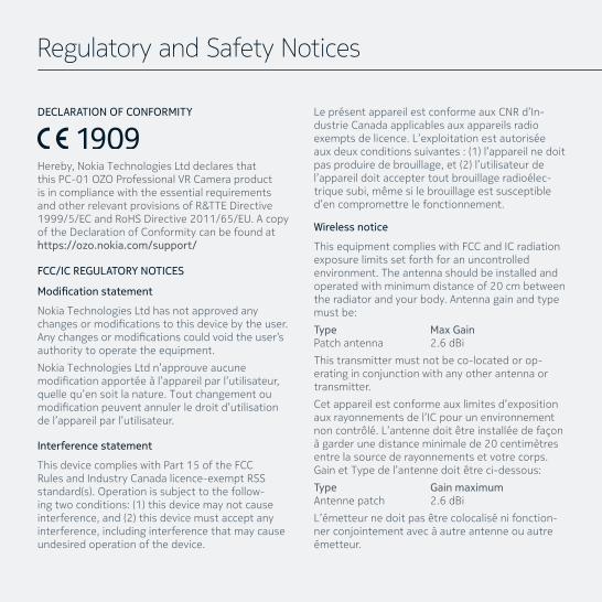
DECLARATION OF CONFORMITY
Hereby, Nokia Technologies Ltd declares that this PC-01 OZO Professional VR Camera product is in compliance with the essential requirements and other relevant provisions of R&TTE Directive 1999/5/EC and RoHS Directive 2011/65/EU. A copy of the Declaration of Conformity can be found at https://ozo.nokia.com/support/
FCC/IC REGULATORY NOTICES
Modification statement
Nokia Technologies Ltd has not approved any changesormodificationstothisdevicebytheuser.Anychangesormodificationscouldvoidtheuser’sauthority to operate the equipment.
Nokia Technologies Ltd n’approuve aucune modificationapportéeàl’appareilparl’utilisateur,quelle qu’en soit la nature. Tout changement ou modificationpeuventannulerledroitd’utilisationde l’appareil par l’utilisateur.
Interference statement
This device complies with Part 15 of the FCC Rules and Industry Canada licence-exempt RSS standard(s).Operationissubjecttothefollow-ingtwoconditions:(1)thisdevicemaynotcauseinterference,and(2)thisdevicemustacceptanyinterference, including interference that may cause undesired operation of the device.
LeprésentappareilestconformeauxCNRd’In-dustrie Canada applicables aux appareils radio exemptsdelicence.L’exploitationestautoriséeauxdeuxconditionssuivantes:(1)l’appareilnedoitpasproduiredebrouillage,et(2)l’utilisateurdel’appareildoitacceptertoutbrouillageradioélec-trique subi, même si le brouillage est susceptible d’en compromettre le fonctionnement.
Wireless notice
This equipment complies with FCC and IC radiation exposure limits set forth for an uncontrolled environment. The antenna should be installed and operated with minimum distance of 20 cm between the radiator and your body. Antenna gain and type must be:
Type Max Gain Patch antenna 2.6 dBi
This transmitter must not be co-located or op-erating in conjunction with any other antenna or transmitter.
Cet appareil est conforme aux limites d’exposition aux rayonnements de l’IC pour un environnement noncontrôlé.L’antennedoitêtreinstalléedefaçonàgarderunedistanceminimalede20centimètresentre la source de rayonnements et votre corps. Gain et Type de l’antenne doit être ci-dessous:
Type Gain maximum Antenne patch 2.6 dBi
L’émetteurnedoitpasêtrecolocalisénifonction-nerconjointementavecàautreantenneouautreémetteur.
Regulatory and Safety Notices
31
FCC Class B digital device notice
This equipment has been tested and found to comply with the limits for a Class B digital device, pursuant to part 15 of the FCC Rules. These limits are designed to provide reasonable protection against harmful interference in a residential instal-lation. This equipment generates, uses and can radiate radio frequency energy and, if not installed and used in accordance with the instructions, may cause harmful interference to radio communica-tions. However, there is no guarantee that inter-ference will not occur in a particular installation. If this equipment does cause harmful interference to radio or television reception, which can be de-terminedbyturningtheequipmentoffandon,theuser is encouraged to try to correct the interfer-ence by one or more of the following measures:
• Reorient or relocate the receiving antenna.• Increase the separation between the equip-
ment and receiver.
• Connect the equipment into an outlet on a circuitdifferentfromthattowhichthereceiveris connected.
• Consult the dealer or an experienced radio/TV technician for help.
CAN ICES-3 (B) / NMB-3 (B)
This Class B digital apparatus complies with Cana-dian ICES-003.
CetappareilnumériquedeclasseBestconformeàla norme canadienne ICES-003.
Wi-Fi
IMPORTANT: Using Wi-Fi may be restricted in certain countries or in certain circumstances. For example, certain countries are currently consid-ering legislation banning the usage of WiFi during national states of emergency. For more information about WiFi usage restrictions please contact your relevant local authorities.
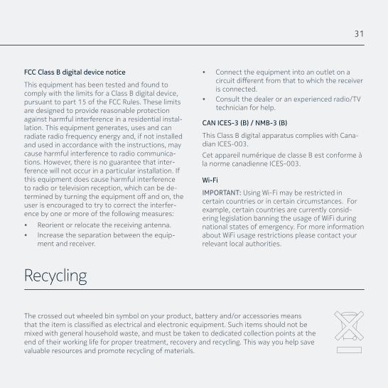
Recycling
The crossed out wheeled bin symbol on your product, battery and/or accessories means thattheitemisclassifiedaselectricalandelectronicequipment.Suchitemsshouldnotbemixed with general household waste, and must be taken to dedicated collection points at the end of their working life for proper treatment, recovery and recycling. This way you help save valuable resources and promote recycling of materials.
O P 1 0 0 - W E - E N - 1 . 2