Embed Size (px)
Citation preview
Oxygen Therapy Door Owner’s Manual
Converts Standard Regal Cage into an Oxygen Therapy Chamber
Door-Mounted Thermometer/Hygrometer Outside compartment for Nebulizer & ice
Models to fit most Single-Door Regal Cages 24”Wx24”H 30”Wx24”H 36”Wx30”H 48”Wx30”H 24”Wx30”H 30”Wx30”H
New Model Numbers: 12156-00-DRDRAA 12156-00-EPDRAA 12156-00-FNEPAA 12156-00-HJEPAA 12156-00-DREPAA 12156-00-EPEPAA
SSCI Contact Information Contact SSCI Customer Service by mail, telephone or fax from 8:30am to 5:00pm,
Central Time, Monday through Friday and closed holidays.
Address: Suburban Surgical Co., Inc. 275 Twelfth street Wheeling, Illinois 60090 Telephone: Illinois-(847)537-9320, ext. 3518 Toll Free-(800)323-7366
Fax: (847)537-9061 Web: www.suburbansurgical.com
E-mail: [email protected]
Form No. 703001
Revised 2/8/13
P a g e | 1
www.SuburbanSurgical.com
Care & Cleaning of Stainless Steel Introduction Stainless steel is steel alloyed with chromium to make it highly resistant to stain, rust and corrosion. Note: This does NOT mean that stainless steel will never rust or corrode. Science has not yet developed a steel which is completely stainless or corrosion PROOF. The type of stainless steel and finish selected by SSCI for the Oxygen Therapy Door is the best available for the intended use.
Cleaning & Cleansers The basic rule of thumb is to use the mildest cleaning procedure that will do the job effectively. Always rinse thoroughly with clear water, and dry completely. Frequent cleaning will prolong the service life of stainless steel equipment and will help maintain a bright, pleasing appearance. Ordinary deposits of waste and fluids can usually be removed with soap and water. More stubborn deposits or tightly adhering debris may require harder scrubbing. They also may possibly require the use of commercial cleaning products acceptable for use on metal surfaces. When using any cleaning agent, rub in the direction of the polish lines or “grain” of the metal. For high luster finishes, clean soft cloths or pads should be used. If especially rough cleaning is necessary, use “stainless steel” wool, nylon or plastic scrubbers. Test these scrubbers in an inconspicuous area first to be sure they do not mark or scratch the stainless steel finish. Minor scale build-up and some hard water spotting may be removed by washing with some vinegar, followed by a neutralizing rinse with clear water. A thorough drying with a soft cloth should follow. For heavy deposits of scale, 5% oxalic acid (use warm), 5-15% sulfuric acid, or 5-10% phosphoric acid may be used. Always follow with a neutralizing rinse of clean water and a thorough drying.
Deodorizing Agents, Disinfectants & Sanitizers The large selection of brands and combinations of chemicals available for deodorizing, disinfecting and sanitizing is staggering. Select one or more agents for use in your facility only after weighing in all the benefits claimed by each product. Often this choice is made without adequate consideration of the effects these agents may produce on equipment or furnishings. CAUTION: Before selecting a chemical to employ in your facility, review label statements regarding use with metals (stainless steel). Always consult the chemical supplier if there are any doubts. Avoid prolonged use of chlorides (such as chlorine bleach), bromides, iodides and thiocyanate on stainless steel surfaces as these chemicals will cause pitting, corrosion and metal discoloration. Allowing salty solutions to evaporate and dry on stainless steel may also contribute to corrosive conditions. In summary, select chemical deodorizers, disinfectants and/or sanitizers only after weighing in all possible outcomes and known adverse effects.
Clear Polycarbonate Cleaning Procedures Rinse the polycarbonate window with clear water and dry thoroughly with a clean, soft cloth. Note: NEVER power-wash the Oxygen Therapy Door.
Ice Tray Cleaning Procedures The ice tray should be removed and washed periodically - at least weekly. With heavy use, more frequent washing may be necessary. Wash the tray in hot, soapy water, rinse with hot clear water, then dry thoroughly with a clean, soft cloth. Open the valve and make sure it is completely cleaned and flushed. Open and close the valve several times to make sure it operates freely.
Nebulizer Cleaning Procedures The nebulizer and bottle should be removed and washed periodically - at least weekly. With heavy use, more frequent washing may be necessary. Wash both items in hot, soapy water, rinse with hot clear water, then dry thoroughly with a clean, soft cloth. Rotate the regulator collar back and forth to make sure it operates freely.
P a g e | 2
www.SuburbanSurgical.com
Chapter 1 - General Information Introduction .................................................................................................................. 4
About Owner’s Manual ................................................................................................. 4 Information & Safety Notices ........................................................................................ 4 “Warnings”/”Notes” ………................................................................................. 4 Models……………………………………………………………………………………………………………………….. 4 Warranty........................................................................................................................ 5 Chapter 2 - Installation & Setup Unpacking & Inspection ................................................................................................ 6 Parts Included................................................................................................... 6 Tools Required ................................................................................................. 6 Procedure ......................................................................................................... 6 Chapter 3 - Operating & Cleaning Opening & Closing ......................................................................................................... 7 Latch Adjustment .............................................................................................. 7 Ice Tray........................................................................................................................... 7 Gauges General Information.......................................................................................... 8 Cautions ............................................................................................................ 8 Maximum/Minimum Temperature & Humidity Recording .............................. 8 Changing Between °C & °F Displays .................................................................. 8 Replacing the Gauge Battery ............................................................................ 8 Using the Nebulizer ....................................................................................................... 9 Oxygen Concentration Control ......................................................................... 9 Chapter 4 - Repairs & Replacements Replacement Parts ......................................................................................................... 10 General Information .......................................................................................... 10 Parts Ordering Procedure ................................................................................. 10 Nebulizer Assembly, Complete ......................................................................... 11 Tool Required....................................................................................... 11 Procedure............................................................................................. 11 Nebulizer Assembly, Partial .............................................................................. 11 Nebulizer Oxygen Supply Hose ......................................................................... 11 Nebulizer Hose Barb Fitting .............................................................................. 12 Tools Required .................................................................................... 12 Procedure............................................................................................. 12 Nebulizer Extension .......................................................................................... 12 Nebulizer Cotter Pin.......................................................................................... 12 Gauge Assembly................................................................................................ 12 Tools Required .................................................................................... 12 Removal - New-style Gauge ................................................................ 12 Installation of New-style Gauge .......................................................... 13 Ice Tray ............................................................................................................. 14 Ice Tray Valve ....................................................................................... 14 Tools Required ..................................................................................... 14 Procedure ............................................................................................. 14 Chapter 5 - Troubleshooting General Problems .......................................................................................................... 15 Returning the Oxygen Therapy Door for Repairs .......................................................... 15

P a g e | 3
www.SuburbanSurgical.com
RMA Numbers................................................................................................... 15 Packing & Shipment .......................................................................................... 15 Remedial Actions………………………………………………………………………………………………………… 16 There is no oxygen flow into the cage............................................................... 16 There is excessive oxygen leakage from the cage............................................. 16 The door does not close or latch correctly ....................................................... 16 One or both of the gauges does not read correctly .......................................... 16
P a g e | 4
www.SuburbanSurgical.com
CHAPTER 1-General Information
Introduction
The SSCI Oxygen Therapy Door transforms your standard Regal Cage into an oxygen therapy chamber. The clear door features a continuous-flow nebulizer with .25 in (.635 cm) inner diameter x .062 in (.16 cm) thick tubing to deliver a regulated flow of medicated, moist oxygen. Oxygen Therapy Doors are available for 24”W x 24”H, 24”W x 30”H, 30”W x 24”H, 30”W x 30”H, 36”W x 30”H, and 48”W x 30”H single door Regal stainless steel cages. Unlike Regal Cage Doors, the Oxygen Therapy Door can only be hinged on the left side and open from the right. A thermometer/ hygrometer mounted on the door monitors cage temperature and humidity for optimal treatment. The clear polycarbonate door allows you to view the animal at all times. A detachable compartment on the outside holds the oxygen nebulizer and ice to cool the oxygen if needed. The door mounts onto the front of the cage in place of the regular door, and uses standard hinges and latches to close securely. This new style door fits and aligns closer and tighter than the older styles, therefore not needing the rubber seals around the Oxygen Therapy door. This new style door still vents out the CO2 from the cage as new Oxygen is introduced.
About Owner’s Manual Every attempt has been made to insure that the information in this manual is correct and complete. SSCI, however, always welcomes our customer’s suggestions for improvements to our products and associated publications.
Information & Safety Notices Throughout this manual you will find text under the headings Note: and WARNING:. The text followed after “Note:” will assist you with additional information about the subject being discussed. The text followed after “Warning:” is there to alert you to potentially hazardous conditions which, if ignored or mishandled, could result in injury to yourself, or damage to the equipment. Example:
Example:
Models
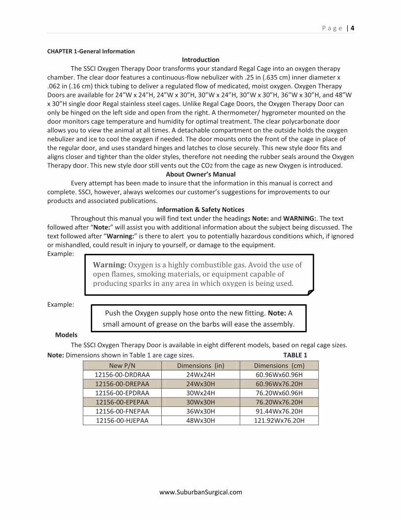
The SSCI Oxygen Therapy Door is available in eight different models, based on regal cage sizes.
Note: Dimensions shown in Table 1 are cage sizes. TABLE 1
New P/N Dimensions (in) Dimensions (cm)
12156-00-DRDRAA 24Wx24H 60.96Wx60.96H
12156-00-DREPAA 24Wx30H 60.96Wx76.20H
12156-00-EPDRAA 30Wx24H 76.20Wx60.96H
12156-00-EPEPAA 30Wx30H 76.20Wx76.20H
12156-00-FNEPAA 36Wx30H 91.44Wx76.20H
12156-00-HJEPAA 48Wx30H 121.92Wx76.20H
Warning: Oxygen is a highly combustible gas. Avoid the use of open flames, smoking materials, or equipment capable of producing sparks in any area in which oxygen is being used.
Push the Oxygen supply hose onto the new fitting. Note: A
small amount of grease on the barbs will ease the assembly.
Warning: Oxygen is a highly combustible gas. Avoid the use of open flames, smoking materials, or equipment capable of producing sparks in any area in which oxygen is being used.

P a g e | 5
www.SuburbanSurgical.com
Warranty Suburban Surgical Company, Inc. warrants the original purchaser that our products are of the highest standards in material and workmanship. Our stainless steel components are guaranteed to last a lifetime assuming they are used as intended, properly maintained and cared for. Mechanical, electrical, electronic, hydraulic, and any product’s devices carry a one year warranty. Items purchased by Suburban Surgical Company, Inc. from other manufacturers and incorporated into our equipment are covered by the respective manufacturer’s warranties. Warranties will not apply if it is determined by Suburban Surgical Company, Inc. that the equipment became defective due to an accident, misuse, abuse, improper maintenance or alteration. Warranty freight charges are covered for the first year only.
P a g e | 6
www.SuburbanSurgical.com
CHAPTER 2-Installation & Setup
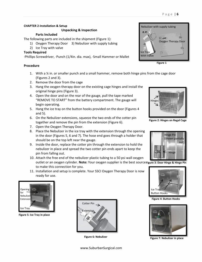
Unpacking & Inspection Parts Included The following parts are included in the shipment (Figure 1):
1) Oxygen Therapy Door 3) Nebulizer with supply tubing 2) Ice Tray with valve
Tools Required ·Phillips Screwdriver, ·Punch (1/4in. dia. max), ·Small Hammer or Mallet Procedure
1. With a ¼ in. or smaller punch and a small hammer, remove both hinge pins from the cage door (Figures 2 and 3).
2. Remove the door from the cage 3. Hang the oxygen therapy door on the existing cage hinges and install the
original hinge pins (Figure 3). 4. Open the door and on the rear of the gauge, pull the tape marked
“REMOVE TO START” from the battery compartment. The gauge will begin operating.
5. Hang the ice tray on the button hooks provided on the door (Figures 4 and 5).
6. On the Nebulizer extensions, squeeze the two ends of the cotter pin together and remove the pin from the extension (Figure 6).
7. Open the Oxygen Therapy Door. 8. Place the Nebulizer in the ice tray with the extension through the opening
in the door (Figures 5, 6 and 7). The hose end goes through a holder that should be on the top left near the gauge.
9. Inside the door, replace the cotter pin through the extension to hold the nebulizer in place and spread the two cotter pin ends apart to keep the pin from falling out.
10. Attach the free end of the nebulizer plastic tubing to a 50 psi wall oxygen outlet or an oxygen cylinder. Note: Your oxygen supplier is the best source to make this connection for you.
11. Installation and setup is complete. Your SSCI Oxygen Therapy Door is now ready for use.
Nebulizer with supply tubing
Ice Tray With Valve
Oxygen Therapy Door
Hinges
Hinge Pin (Shown partially out)
Hinge
Ice Tray Button Hooks
Opening for Nebulizer Extension
Ice Tray
Figure 2: Hinges on Regal Cage
Figure 1
Figure 3: Door Hinge & Hinge Pin
Figure 4: Button Hooks
Figure 5: Ice Tray in place
Figure 6: Nebulizer Figure 7: Nebulizer in place
Cotter Pin Extension
P a g e | 7
www.SuburbanSurgical.com
CHAPTER 3-Operating & Cleaning
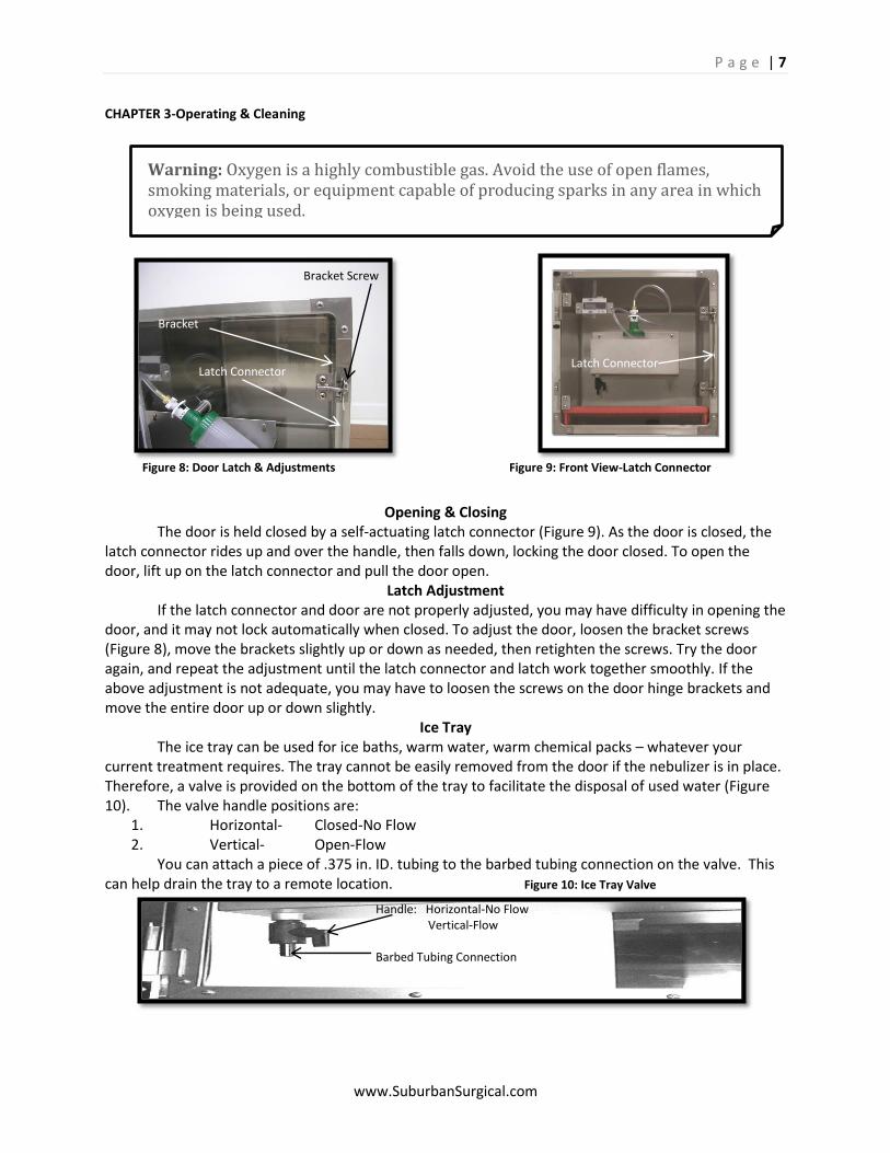
Opening & Closing The door is held closed by a self-actuating latch connector (Figure 9). As the door is closed, the latch connector rides up and over the handle, then falls down, locking the door closed. To open the door, lift up on the latch connector and pull the door open.
Latch Adjustment If the latch connector and door are not properly adjusted, you may have difficulty in opening the door, and it may not lock automatically when closed. To adjust the door, loosen the bracket screws (Figure 8), move the brackets slightly up or down as needed, then retighten the screws. Try the door again, and repeat the adjustment until the latch connector and latch work together smoothly. If the above adjustment is not adequate, you may have to loosen the screws on the door hinge brackets and move the entire door up or down slightly.
Ice Tray The ice tray can be used for ice baths, warm water, warm chemical packs – whatever your current treatment requires. The tray cannot be easily removed from the door if the nebulizer is in place. Therefore, a valve is provided on the bottom of the tray to facilitate the disposal of used water (Figure 10). The valve handle positions are:
1. Horizontal- Closed-No Flow 2. Vertical- Open-Flow
You can attach a piece of .375 in. ID. tubing to the barbed tubing connection on the valve. This can help drain the tray to a remote location. Figure 10: Ice Tray Valve
Warning: Oxygen is a highly combustible gas. Avoid the use of open flames, smoking materials, or equipment capable of producing sparks in any area in which oxygen is being used.
Latch Connector
Bracket Screw Bracket Latch Connector
Handle: Horizontal-No Flow Vertical-Flow Barbed Tubing Connection
Figure 8: Door Latch & Adjustments Figure 9: Front View-Latch Connector
P a g e | 8
www.SuburbanSurgical.com
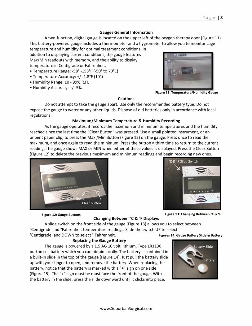
Figure 11: Temperature/Humidity Gauge
Gauges General Information A two-function, digital gauge is located on the upper left of the oxygen therapy door (Figure 11). This battery-powered gauge includes a thermometer and a hygrometer to allow you to monitor cage temperature and humidity for optimal treatment conditions. In addition to displaying current conditions, the gauge features Max/Min readouts with memory, and the ability to display temperature in Centigrade or Fahrenheit. • Temperature Range: -58° -158°F (-50° to 70°C) • Temperature Accuracy: +/- 1.8°F (1°C) • Humidity Range: 10 - 99% R.H. • Humidity Accuracy: +/- 5%
Cautions
Do not attempt to take the gauge apart. Use only the recommended battery type. Do not expose the gauge to water or any other liquids. Dispose of old batteries only in accordance with local regulations.
Maximum/Minimum Temperature & Humidity Recording As the gauge operates, it records the maximum and minimum temperatures and the humidity reached since the last time the “Clear Button” was pressed. Use a small pointed instrument, or an unbent paper clip, to press the Max /Min Button (Figure 12) on the gauge. Press once to read the maximum, and once again to read the minimum. Press the button a third time to return to the current reading. The gauge shows MAX or MIN when either of these values is displayed. Press the Clear Button (Figure 12) to delete the previous maximum and minimum readings and begin recording new ones.
Changing Between °C & °F Displays A slide switch on the front side of the gauge (Figure 13) allows you to select between °Centigrade and °Fahrenheit temperature readings. Slide the switch UP to select °Centigrade; and DOWN to select ° Fahrenheit. Figures 14: Gauge Battery Slide & Battery
Replacing the Gauge Battery The gauge is powered by a 1.5 AG 10 volt, lithium, Type LR1130 button cell battery which you can obtain locally. The battery is contained in a built-in slide in the top of the gauge (Figure 14). Just pull the battery slide up with your finger to open, and remove the battery. When replacing the battery, notice that the battery is marked with a “+” sign on one side (Figure 15). The “+” sign must be must face the front of the gauge. With the battery in the slide, press the slide downward until it clicks into place.
Figure 12: Gauge Buttons
Figure 13: Changing Between °C & °F
Max/Min Button Clear Button
°C & ̊°F Slide Switch
Battery Slide Battery
P a g e | 9
www.SuburbanSurgical.com
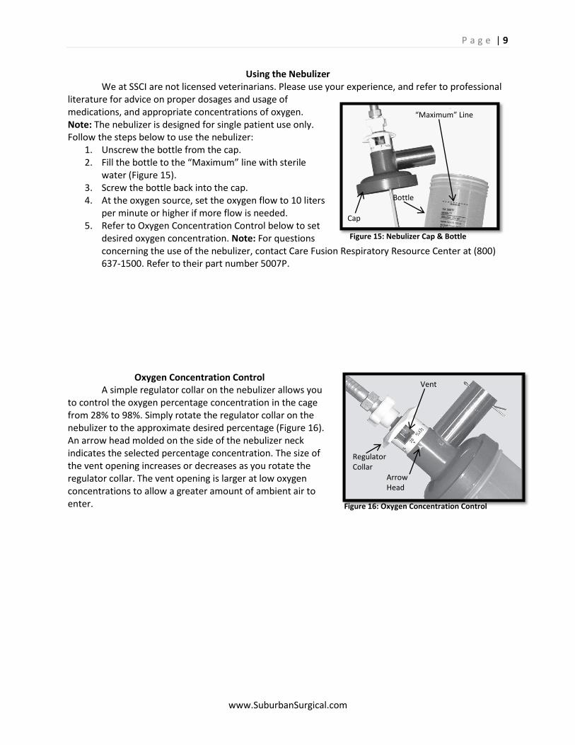
Using the Nebulizer We at SSCI are not licensed veterinarians. Please use your experience, and refer to professional literature for advice on proper dosages and usage of medications, and appropriate concentrations of oxygen. Note: The nebulizer is designed for single patient use only. Follow the steps below to use the nebulizer:
1. Unscrew the bottle from the cap. 2. Fill the bottle to the “Maximum” line with sterile
water (Figure 15). 3. Screw the bottle back into the cap. 4. At the oxygen source, set the oxygen flow to 10 liters
per minute or higher if more flow is needed. 5. Refer to Oxygen Concentration Control below to set
desired oxygen concentration. Note: For questions concerning the use of the nebulizer, contact Care Fusion Respiratory Resource Center at (800) 637-1500. Refer to their part number 5007P.
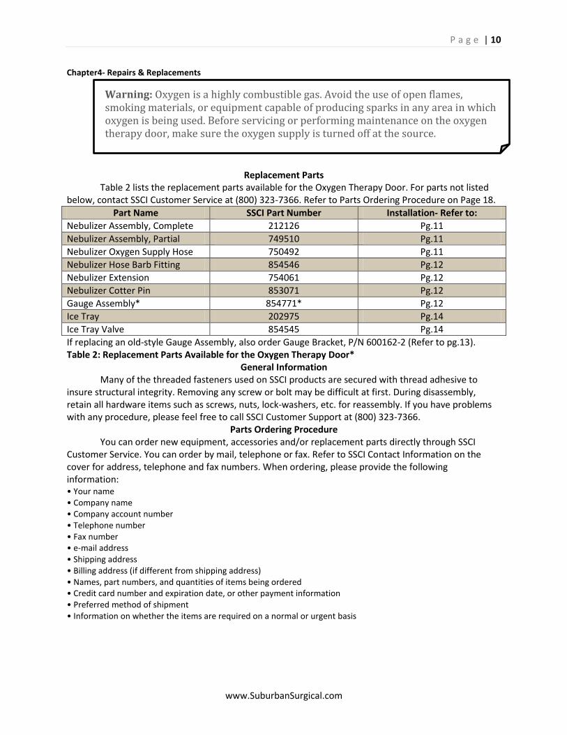
Oxygen Concentration Control
A simple regulator collar on the nebulizer allows you to control the oxygen percentage concentration in the cage from 28% to 98%. Simply rotate the regulator collar on the nebulizer to the approximate desired percentage (Figure 16). An arrow head molded on the side of the nebulizer neck indicates the selected percentage concentration. The size of the vent opening increases or decreases as you rotate the regulator collar. The vent opening is larger at low oxygen concentrations to allow a greater amount of ambient air to enter.
“Maximum” Line Bottle Cap
Vent Regulator Collar Arrow Head
Figure 15: Nebulizer Cap & Bottle
Figure 16: Oxygen Concentration Control
P a g e | 10
www.SuburbanSurgical.com
Warning: Oxygen is a highly combustible gas. Avoid the use of open flames, smoking materials, or equipment capable of producing sparks in any area in which oxygen is being used. Before servicing or performing maintenance on the oxygen therapy door, make sure the oxygen supply is turned off at the source.
Chapter4- Repairs & Replacements
Replacement Parts Table 2 lists the replacement parts available for the Oxygen Therapy Door. For parts not listed below, contact SSCI Customer Service at (800) 323-7366. Refer to Parts Ordering Procedure on Page 18.
Part Name SSCI Part Number Installation- Refer to:
Nebulizer Assembly, Complete 212126 Pg.11
Nebulizer Assembly, Partial 749510 Pg.11
Nebulizer Oxygen Supply Hose 750492 Pg.11
Nebulizer Hose Barb Fitting 854546 Pg.12
Nebulizer Extension 754061 Pg.12
Nebulizer Cotter Pin 853071 Pg.12
Gauge Assembly* 854771* Pg.12
Ice Tray 202975 Pg.14
Ice Tray Valve 854545 Pg.14
If replacing an old-style Gauge Assembly, also order Gauge Bracket, P/N 600162-2 (Refer to pg.13). Table 2: Replacement Parts Available for the Oxygen Therapy Door*
General Information Many of the threaded fasteners used on SSCI products are secured with thread adhesive to insure structural integrity. Removing any screw or bolt may be difficult at first. During disassembly, retain all hardware items such as screws, nuts, lock-washers, etc. for reassembly. If you have problems with any procedure, please feel free to call SSCI Customer Support at (800) 323-7366.
Parts Ordering Procedure You can order new equipment, accessories and/or replacement parts directly through SSCI Customer Service. You can order by mail, telephone or fax. Refer to SSCI Contact Information on the cover for address, telephone and fax numbers. When ordering, please provide the following information: • Your name • Company name • Company account number • Telephone number • Fax number • e-mail address • Shipping address • Billing address (if different from shipping address) • Names, part numbers, and quantities of items being ordered • Credit card number and expiration date, or other payment information • Preferred method of shipment • Information on whether the items are required on a normal or urgent basis
P a g e | 11
www.SuburbanSurgical.com
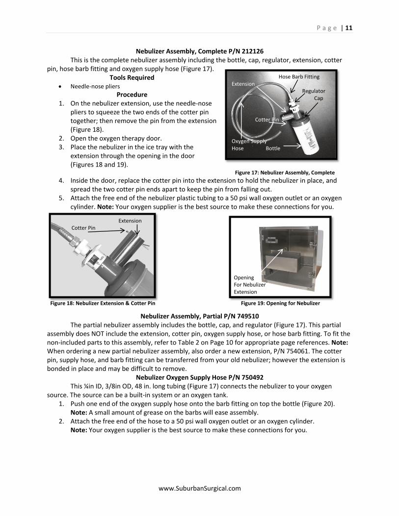
Nebulizer Assembly, Complete P/N 212126 This is the complete nebulizer assembly including the bottle, cap, regulator, extension, cotter pin, hose barb fitting and oxygen supply hose (Figure 17).
Tools Required Needle-nose pliers
Procedure 1. On the nebulizer extension, use the needle-nose
pliers to squeeze the two ends of the cotter pin together; then remove the pin from the extension (Figure 18).
2. Open the oxygen therapy door. 3. Place the nebulizer in the ice tray with the
extension through the opening in the door (Figures 18 and 19). Figure 17: Nebulizer Assembly, Complete
4. Inside the door, replace the cotter pin into the extension to hold the nebulizer in place, and spread the two cotter pin ends apart to keep the pin from falling out.
5. Attach the free end of the nebulizer plastic tubing to a 50 psi wall oxygen outlet or an oxygen cylinder. Note: Your oxygen supplier is the best source to make these connections for you.
Nebulizer Assembly, Partial P/N 749510 The partial nebulizer assembly includes the bottle, cap, and regulator (Figure 17). This partial assembly does NOT include the extension, cotter pin, oxygen supply hose, or hose barb fitting. To fit the non-included parts to this assembly, refer to Table 2 on Page 10 for appropriate page references. Note: When ordering a new partial nebulizer assembly, also order a new extension, P/N 754061. The cotter pin, supply hose, and barb fitting can be transferred from your old nebulizer; however the extension is bonded in place and may be difficult to remove.
Nebulizer Oxygen Supply Hose P/N 750492 This ¼in ID, 3/8in OD, 48 in. long tubing (Figure 17) connects the nebulizer to your oxygen source. The source can be a built-in system or an oxygen tank.
1. Push one end of the oxygen supply hose onto the barb fitting on top the bottle (Figure 20). Note: A small amount of grease on the barbs will ease assembly.
2. Attach the free end of the hose to a 50 psi wall oxygen outlet or an oxygen cylinder. Note: Your oxygen supplier is the best source to make these connections for you.
Hose Barb Fitting Extension Regulator Cap Cotter Pin Oxygen Supply Hose Bottle
Figure 18: Nebulizer Extension & Cotter Pin Figure 19: Opening for Nebulizer
Extension Cotter Pin
Opening For Nebulizer Extension
P a g e | 12
www.SuburbanSurgical.com
Nebulizer Hose Barb Fitting P/N 854546 Tools Required • 5/8 in. open-end wrench • Utility knife
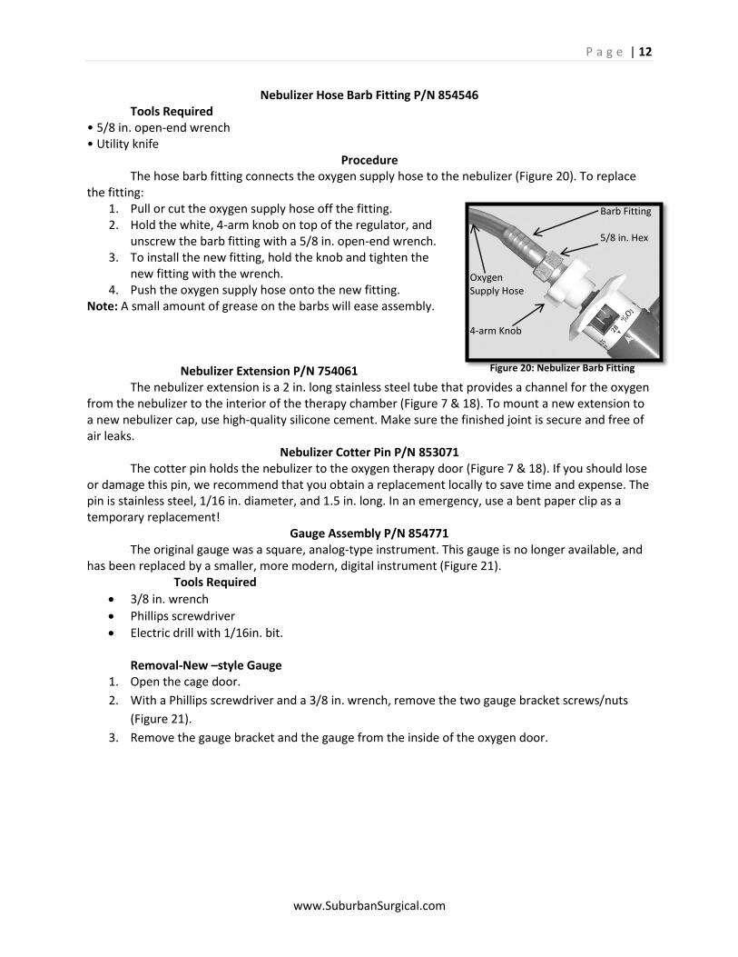
Procedure The hose barb fitting connects the oxygen supply hose to the nebulizer (Figure 20). To replace the fitting:
1. Pull or cut the oxygen supply hose off the fitting. 2. Hold the white, 4-arm knob on top of the regulator, and
unscrew the barb fitting with a 5/8 in. open-end wrench. 3. To install the new fitting, hold the knob and tighten the
new fitting with the wrench. 4. Push the oxygen supply hose onto the new fitting.
Note: A small amount of grease on the barbs will ease assembly.
Nebulizer Extension P/N 754061
The nebulizer extension is a 2 in. long stainless steel tube that provides a channel for the oxygen from the nebulizer to the interior of the therapy chamber (Figure 7 & 18). To mount a new extension to a new nebulizer cap, use high-quality silicone cement. Make sure the finished joint is secure and free of air leaks.
Nebulizer Cotter Pin P/N 853071 The cotter pin holds the nebulizer to the oxygen therapy door (Figure 7 & 18). If you should lose or damage this pin, we recommend that you obtain a replacement locally to save time and expense. The pin is stainless steel, 1/16 in. diameter, and 1.5 in. long. In an emergency, use a bent paper clip as a temporary replacement!
Gauge Assembly P/N 854771 The original gauge was a square, analog-type instrument. This gauge is no longer available, and has been replaced by a smaller, more modern, digital instrument (Figure 21). Tools Required
3/8 in. wrench
Phillips screwdriver
Electric drill with 1/16in. bit. Removal-New –style Gauge
1. Open the cage door.
2. With a Phillips screwdriver and a 3/8 in. wrench, remove the two gauge bracket screws/nuts
(Figure 21).
3. Remove the gauge bracket and the gauge from the inside of the oxygen door.
Barb Fitting 5/8 in. Hex Oxygen Supply Hose 4-arm Knob
Figure 20: Nebulizer Barb Fitting
P a g e | 13
www.SuburbanSurgical.com
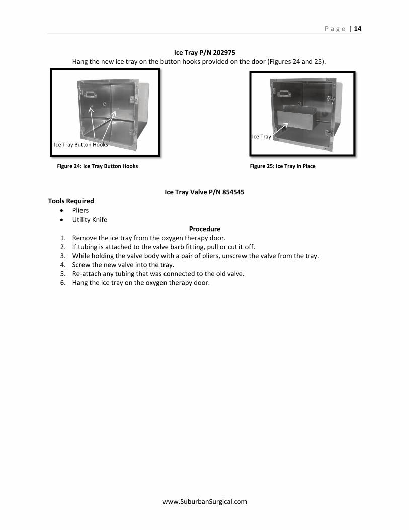
Figure 23: Drilling Button Access Holes
Installation of New-style Gauge
1. Order the following from SSCI:
• New-style Gauge - P/N 854771 • Gauge Bracket - P/N 600162-2 Note: Order a new gauge bracket only if replacing an old-style gauge. If replacing a new-style gauge, use your existing bracket.
2. Loosely mount the gauge bracket onto the inside of the oxygen door with the screws and nuts removed above. Use the existing gauge bracket mounting holes.
3. Place the gauge into the gauge bracket making sure the gauge is right-side-up. 4. Tighten the bracket screws and nuts to secure the gauge. 5. On the front of the polycarbonate door, mark the centers of the two buttons on the face of the
gauge (Figure 23). 6. Loosen the gauge bracket nuts and remove the gauge from the door. 7. With a 1/16 in. bit, drill two holes in the door at the locations marked in Step 5 (Figure 23). This
will provide easy access to the buttons on the front of the gauge. 8. Smooth out the outside and inside edges of the holes to eliminate any rough edges. 9. Remove the tape marked “REMOVE TO START” from the battery compartment. When the tape
is removed, the gauge will begin operating. 10. Position the Centigrade/Fahrenheit (°C / °F) slide switch to display the preferred units (Refer to
Page 8). 11. Place the gauge into the gauge bracket, again making sure the
gauge is right-side-up. 12. Tighten the screws and nuts to secure the gauge.
Gauge Bracket Screws
Gauge Bracket
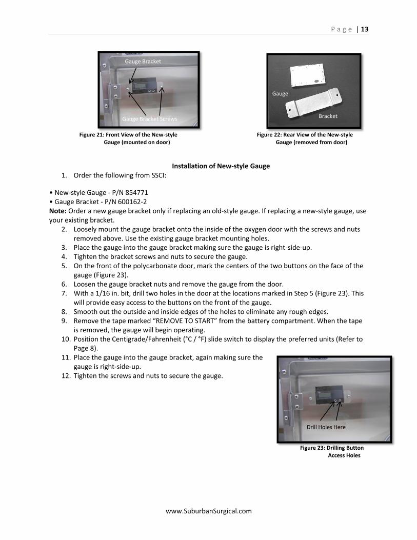
Gauge Bracket
Figure 21: Front View of the New-style Figure 22: Rear View of the New-style Gauge (mounted on door) Gauge (removed from door)
Drill Holes Here
P a g e | 14
www.SuburbanSurgical.com
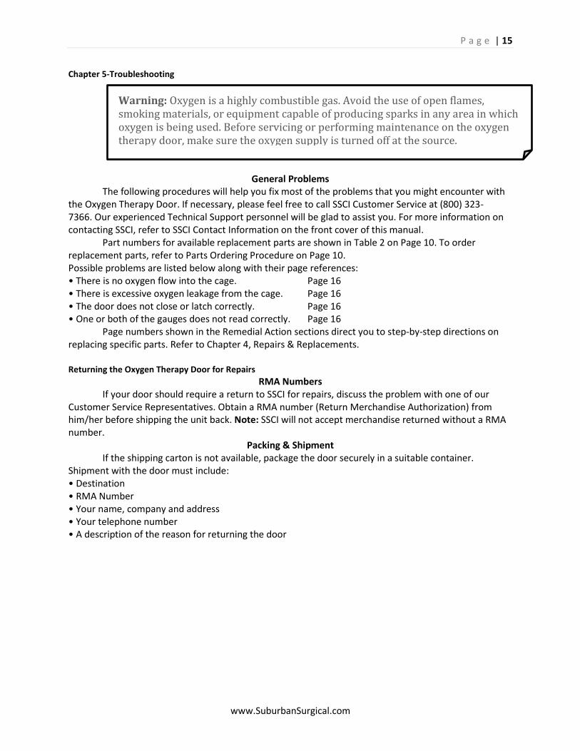
Ice Tray P/N 202975 Hang the new ice tray on the button hooks provided on the door (Figures 24 and 25).
Ice Tray Valve P/N 854545
Tools Required
Pliers
Utility Knife Procedure
1. Remove the ice tray from the oxygen therapy door. 2. If tubing is attached to the valve barb fitting, pull or cut it off. 3. While holding the valve body with a pair of pliers, unscrew the valve from the tray. 4. Screw the new valve into the tray. 5. Re-attach any tubing that was connected to the old valve. 6. Hang the ice tray on the oxygen therapy door.
Ice Tray Button Hooks
Ice Tray
Figure 24: Ice Tray Button Hooks Figure 25: Ice Tray in Place
P a g e | 15
www.SuburbanSurgical.com
Warning: Oxygen is a highly combustible gas. Avoid the use of open flames, smoking materials, or equipment capable of producing sparks in any area in which oxygen is being used. Before servicing or performing maintenance on the oxygen therapy door, make sure the oxygen supply is turned off at the source.
Chapter 5-Troubleshooting
General Problems The following procedures will help you fix most of the problems that you might encounter with the Oxygen Therapy Door. If necessary, please feel free to call SSCI Customer Service at (800) 323- 7366. Our experienced Technical Support personnel will be glad to assist you. For more information on contacting SSCI, refer to SSCI Contact Information on the front cover of this manual. Part numbers for available replacement parts are shown in Table 2 on Page 10. To order replacement parts, refer to Parts Ordering Procedure on Page 10. Possible problems are listed below along with their page references: • There is no oxygen flow into the cage. Page 16 • There is excessive oxygen leakage from the cage. Page 16 • The door does not close or latch correctly. Page 16 • One or both of the gauges does not read correctly. Page 16 Page numbers shown in the Remedial Action sections direct you to step-by-step directions on replacing specific parts. Refer to Chapter 4, Repairs & Replacements. Returning the Oxygen Therapy Door for Repairs
RMA Numbers If your door should require a return to SSCI for repairs, discuss the problem with one of our Customer Service Representatives. Obtain a RMA number (Return Merchandise Authorization) from him/her before shipping the unit back. Note: SSCI will not accept merchandise returned without a RMA number.
Packing & Shipment If the shipping carton is not available, package the door securely in a suitable container. Shipment with the door must include: • Destination • RMA Number • Your name, company and address • Your telephone number • A description of the reason for returning the door
P a g e | 16
www.SuburbanSurgical.com
Remedial Actions
There is no Oxygen Flow into the cage 1. Make sure that the oxygen supply is turned on at the source and that your oxygen supply tank is
not empty. 2. Make sure the oxygen therapy door is properly closed with the latch and not allowing oxygen to
escape. 3. Make sure the nebulizer bottle is in place and fully tightened. 4. Check the regulator on the nebulizer to make sure it is properly adjusted. Refer to Oxygen
Concentration Control on Page 9. 5. Check the oxygen supply hose for kinks, leaks, or clogs. If the hose is kinked or restricted at any
point, straighten the hose to remove the restriction. If you find a leak, immediately turn off the oxygen supply at the source.
a) If the leak is at the oxygen source, call your oxygen supplier for repairs. b) If the leak is in the oxygen supply hose, call SSCI and order a replacement hose, P/N 750492. Refer to Page 11 for replacement procedures. c) If the leak is at the supply hose barb connector, remove the hose from the connector. Cut about 1.5 in. off the end of the hose, and reconnect the hose to the barb connector. d) If the leak is between the barb connector and the 4-arm knob on top the regulator, try to tighten the barb connector with a 5/8 in. wrench. If this doesn’t stop the leak, there are probably damaged threads on the barb connector or in the regulator. Call SSCI and order a replacement barb fitting, P/N 854546 or a partial nebulizer assembly, P/N 749510. Refer to Page 12 for replacement instructions for the barb fitting, or Page 11 for the partial nebulizer assembly.
6. Dirt or foreign matter may have entered the nebulizer and is blocking the oxygen flow. Refer to Cleaning Instructions on Page 1.
There is excessive oxygen leakage from the cage Note: Some oxygen leakage is normal. The corners of the cage are left open to help distribute the oxygen in the cage uniformly and to allow the escape of carbon dioxide. If you feel that the amount of leakage is excessive, perform the following steps.
1. Make sure the door is properly closed and latched. If the door does not close or latch properly, the latch brackets are probably out of adjustment. Refer to Latch Adjustment on Page 7.
2. Make sure the oxygen supply pressure is not set too high. 3. This new style door does not have the rubber seals around the perimeter, yet it is aligned closer
and hung tighter. This door still allows the proper escape of CO2 as new Oxygen is introduced to the unit. Check the alignment and make sure the door operates freely.
The Door does not close or latch correctly The latch brackets are probably out of adjustment. Refer to Latch Adjustment on Page 7.
One or both gauges does not read correctly One or both of the gauges is defective. The gauges are not repairable and must be replaced. Call SSCI and order a new gauge assembly, P/N 854771. Refer to Page 12 for replacement procedures.

P a g e | 17
www.SuburbanSurgical.com
© Copyright 2013 by Suburban Surgical Co., Inc. All rights reserved. No part of this document may be reproduced or utilized in any form or by any means, electronic or mechanical,
including photocopying, recording, or by any information storage and retrieval system without written permission.
Inquiries should be addressed to Suburban Surgical Co., Inc. Wheeling, Illinois 60090