Embed Size (px)
Citation preview
Ol
WSa
b
c
a
ARRAA
KPCOEOM
1
tp[pcctrTmmlci[
0d
Applied Catalysis B: Environmental 97 (2010) 347–353
Contents lists available at ScienceDirect
Applied Catalysis B: Environmental
journa l homepage: www.e lsev ier .com/ locate /apcatb
xygen reduction on Pd3Pt1 bimetallic nanoparticles highlyoaded on different carbon supports
ei Hea, Mei Chenb, Zhiqing Zoub, Zhilin Lib, Xiaogang Zhanga,eon-Ah Jinc, Dae Jong Youc, Chanho Pakc, Hui Yangb,∗
College of Materials Science and Engineering, Nanjing University of Aeronautics and Astronautics, Nanjing 210016, ChinaShanghai Institute of Microsystem and Information Technology, Chinese Academy of Sciences, 865 Changning Road, Shanghai 200050, ChinaEnergy Lab., Emerging Technology Center, Samsung Advanced Institute of Technology (SAIT), Samsung Electronics, Suwon 440-600, Republic of Korea
r t i c l e i n f o
rticle history:eceived 8 January 2010eceived in revised form 28 March 2010ccepted 13 April 2010vailable online 18 April 2010
eywords:d–Pt alloy
a b s t r a c t
The development of new cost-effective cathode catalysts with high methanol tolerance and at a high cata-lyst loading is highly desirable for the direct methanol fuel cell. The Pd3Pt1 bimetallic alloy nanoparticleshighly loaded on different carbon supports, including Vulcan XC-72R carbon, single and multi-walledcarbon nanotubes (SWCNTs/MWCNTs) and ordered mesoporous carbon (OMC), have been prepared bya modified polyol reduction route. The activities of the catalysts for the oxygen reduction reaction (ORR)have been studied based on the rotating disk and ring-disk electrode (RDE/RRDE) techniques in pure andmethanol-containing electrolytes. X-ray diffraction indicates that all the Pd3Pt1/C nanoparticles evidence
arbon nanotuberdered mesoporous carbonlectrocatalysisxygen reduction reactionethanol tolerance
a single-phase fcc disordered structure. The mean particle size of Pd3Pt1 alloy nanoparticles on differentsupports is ca. 4–5 nm even at a metal loading of 50 wt%. Among various carbons supported catalysts,the highest ORR activity, found on the OMC-supported Pd3Pt1 catalyst, even surpasses that on the com-mercial Pt/C catalyst. Kinetic analysis reveals that the ORR on the Pd3Pt1/OMC catalyst predominantlyundergoes a four-electron process, leading to water formation. Furthermore, the Pd3Pt1/OMC catalystexhibited a higher methanol tolerance during the ORR than the commercial Pt/C catalyst; ensuring ahigher ORR performance while diminishing Pt utilization.
. Introduction
Because of system simplicity and environmental friendliness,he direct methanol fuel cell (DMFC) has been considered as aromising energy converter for a variety of portable applications1,2]. However, several challenges need to be addressed before itsractical application. Examples include the high costs of Pt-basedatalysts, slow kinetics of both anode and cathode reactions and therossover of methanol from the anode to the cathode. In particular,he activity improvement of the oxygen reduction reaction (ORR)epresents one of the important issues in fuel cell development.o address the crossover problem, one strategy is the develop-ent of novel ORR catalysts with high catalytic activity and goodethanol tolerance [3,4]. Efforts to this end have involved the uti-
ization of Pd-based alloy catalysts, not only because of the lowerosts and more abundance but also because of the lower reactiv-ty observed for the Pd-based alloys toward methanol oxidation5,6]. The ORR activity enhancement on these Pd alloy catalysts
∗ Corresponding author. Fax: +86 21 32200534.E-mail addresses: [email protected], [email protected] (H. Yang).
926-3373/$ – see front matter © 2010 Elsevier B.V. All rights reserved.oi:10.1016/j.apcatb.2010.04.015
© 2010 Elsevier B.V. All rights reserved.
has been attributed to several factors, including effects that areelectronic and structural in nature [7–9]. Among the Pd–M alloycatalysts investigated in the literature, novel Pd–Pt alloy catalystmight be a promising candidate as methanol-tolerant ORR catalysts[10–12] because the long-term stability of Pd in acidic solution iscomparable with Pt.
It is well known that the basic properties of supported catalystsare strongly influenced by the impregnation method, the micro-scopic nature of the structure, the surface reactivity, the metalprecursor used, and the dispersion of nanoparticles. For the lat-ter issue, the morphology and nanostructure of carbon supportsare considered to be main factors in obtaining high dispersion andthus enhanced catalytic activities of nanoparticle catalysts [13,14].Efforts to this issue have involved the exploration of various car-bon materials as supports, such as activated carbon, single andmulti-walled carbon nanotubes (SWCNTs/MWCNTs) [15,16], car-bon nanofibers [17] and ordered mesoporous carbons (OMCs) [18].
Especially, the OMCs, due to their appealing structural character-istics such as periodic and uniform mesopores and high surfacearea, have recently received much attention for their potential useas catalyst supports in fuel cells. Nanoporous carbons with 3Dordered pore structures have also demonstrated to improve the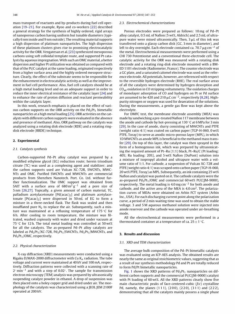
3 : Env
maaocaoacldtfttmartw
onaaad
2
2
mctNptS5ptmit6t7flP
2
Rvt2estpo
48 W. He et al. / Applied Catalysis B
ass transport of reactants and by-products during fuel cell oper-tion [19–21]. For example, Ryoo and co-workers [22] describedgeneral strategy for the synthesis of highly ordered, rigid arraysf nanoporous carbon having uniform but tunable diameters (typi-ally 6 nm inside and 9 nm outside). The resulting material supportshigh dispersion of platinum nanoparticles. The high dispersion
f these platinum clusters gives rise to promising electrocatalyticctivity for the ORR. Vengatesan et al. [23] synthesized mesoporousarbons using soft colloidal template route, and supported Pt cata-ysts by aqueous impregnation. With such an OMC material, a betterispersion and higher Pt utilization was obtained as compared withhat of the Pt/C catalyst at the same loading, originated respectivelyrom a higher surface area and the highly ordered mesopore struc-ure. Clearly, the effect of the substrate seems to be responsible forhe enhancement in electrocatalytic activity as well as the improve-
ent in fuel cell performance. Also, fuel cell catalysts should be athigh metal loading level and on an adequate support in order to
educe the inner electrical resistance of the catalytic layer [24] ando enhance the rate of proton diffusion and reactant permeabilityithin the catalytic layer.
In this work, research emphasis is placed on the effect of vari-us carbon supports on the ORR activity on the Pd3Pt1 bimetallicanoparticles at a high metal loading [25]. ORR activities on the cat-lysts with different carbon supports were evaluated in the absencend presence of methanol. Also, ORR pathway on the catalysts wasnalyzed using a rotating disk electrode (RDE) and a rotating ring-isk electrode (RRDE) technique.
. Experimental
.1. Catalysts synthesis
Carbon-supported Pd–Pt alloy catalyst was prepared by aodified ethylene glycol (EG) reduction route; herein trisodium
itrate (TC) was used as a complexing agent and stabilizer; andhe carbon supports used are Vulcan XC-72R, SWCNTs, MWC-Ts and OMC. Purified SWCNTs and MWCNTs are commercialroducts from Shenzhen Nanotech. Port. Co. Ltd. without fur-her functionalization. The OMC support was obtained fromAIT with a surface area of 680 m2 g−1 and a pore size ofnm [26,27]. Topically, a given amount of carbon material, TC,alladium acetylacetonate [Pd(acac)2] and platinum acetylace-onate [Pt(acac)2] were dispersed in 50 mL of EG to form a
ixture in a three-necked flask. The flask was sealed and thennsufflated pure N2 to replace the air. Subsequently, such a mix-ure was maintained at a refluxing temperature of 175 ◦C forh. After cooling to room temperature, the mixture was fil-
rated, washed copiously with water and dried under vacuum at5 ◦C for 12 h. The total metal loading was controlled at 50 wt%or all the catalysts. The as-prepared Pd–Pt alloy catalysts areabeled as Pd3Pt1/XC-72R, Pd3Pt1/SWCNTs, Pd3Pt1/MWCNTs, andd3Pt1/OMC, respectively.
.2. Physical characterization
X-ray diffraction (XRD) measurements were conducted using aigaku D/MAX-2000 diffractometer with Cu K� radiation. The tubeoltage and current were maintained at 40 kV and 100 mA, respec-ively. Diffraction patterns were collected with a scanning rate of◦ min−1 and with a step of 0.02◦. The sample for transmission
lectron microscopy (TEM) analysis was prepared by ultrasonicallyuspending catalyst powder in ethanol. A drop of suspension washen placed onto a holey copper grid and dried under air. The mor-hology of the catalysts was characterized using a JEOL JEM 2100Fperated at 200 kV.ironmental 97 (2010) 347–353
2.3. Electrochemical characterizations
Porous electrodes were prepared as follows: 10 mg of Pd–Ptalloy catalyst, 0.5 mL of Nafion (5 wt%, Aldrich) and 2.5 mL of ultra-pure water were mixed ultrasonically. Then, 3 �L of this ink wastransferred onto a glassy carbon disk (GC, 3 mm in diameter), andleft to dry overnight. Each electrode contained ca. 70.7 �g cm−2 ofthe metal. Electrochemical measurements were performed using aCHI 730 Potentiostat and a conventional three-electrode cell. Thecatalytic activity for the ORR was measured with a rotating diskelectrode and a rotating ring-disk electrode mounted with a BM-ED 1101 electrode (Radiometer, France). The counter electrode wasa GC plate, and a saturated calomel electrode was used as the refer-ence electrode. All potentials, however, are referenced with respectto the reversible hydrogen electrode (RHE). The real surface areasof all the catalysts were determined by hydrogen desorption andCOad oxidation in CO stripping voltammetry. The oxidation chargesof monolayer adsorption of CO and hydrogen on Pt or Pd surfaceare assumed to be 420 and 210 �C cm−2, respectively [8,28]. High-purity nitrogen or oxygen was used for deaeration of the solutions.During the measurements, a gentle gas flow was kept above theelectrolyte.
For DMFC test, the membrane electrode assembly (MEA) wasmade by sandwiching a pre-treated Nafion 117 membrane betweenthe anode and cathode by hot-pressing at 130 ◦C at 6 MPa for 3 min[29]. In the case of anode, slurry consisting of MWCNTs and PTFE(weight ratio 4:1) was coated on carbon paper (TGP-H-060, 0 wt%PTFE, Toray) to serve as anodic micro-porous layer (MPL), in which1D MWCNTs as anode MPL is beneficial to the methanol mass trans-fer [29]. On top of this layer, the catalyst was then sprayed in theform of a homogenous ink, which was prepared by ultrasonicat-ing the required amount of Pt–Ru (1:1) black, Pt–Ru/C (Pt loading:40%; Ru loading: 20%), and 5 wt% Nafion (DuPont) solution intoa mixture of isopropyl alcohol and ultrapure water with a vol-ume ratio of 1:1. For cathode, a suspension of Vulcan XC-72R andPTFE (weight ratio 4:1) was scraped onto carbon paper (TGP-H-060,20 wt% PTFE, Toray) as MPL. Subsequently, an ink containing 25 wt%Nafion and catalyst was pasted on it. The cathode catalysts were theas-prepared Pd3Pt1/OMC and commercial 60 wt% Pt/C(JM-9000),respectively. The metal loading is 4.0 mg cm−2 for both anode andcathode, and the active area of the MEA is 4.0 cm2. The polariza-tion curves of MEAs were obtained on Arbin FCT system (ArbinInc., USA). For each discharging current point along the polarizationcurve, a period of 2 min waiting time was used to obtain the stablevoltage. 3 and 5 M aqueous methanol solution were injected intoanode reservoir and the cathode was operated under air-breathingmode.
All the electrochemical measurements were performed in athermostated container at a temperature of ca. 25 ± 1 ◦C.
3. Results and discussion
3.1. XRD and TEM characterization
The average bulk composition of the Pd–Pt bimetallic catalystswas evaluated using an ICP-AES analysis. The obtained results arenearly the same as original stoichiometric values, suggesting that asa result of our synthesis methodology Pd and Pt are totally reducedto form Pd/Pt bimetallic nanoparticles.
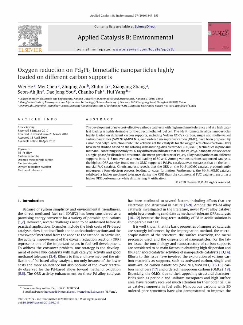
Fig. 1 shows the XRD patterns of Pd3Pt1 nanoparticles on dif-
ferent carbon supports and the commercial Pt/C(JM-9000) catalystwith Pt loading of 60 wt%. All the XRD patterns clearly show fivemain characteristic peaks of face-centered-cubic (fcc) crystallinePd, namely, the planes (1 1 1), (2 0 0), (2 2 0), (3 1 1) and (2 2 2),demonstrating that all the catalysts mainly possess a single phase
W. He et al. / Applied Catalysis B: Env
Fc
fraofawtPsat(pattO
dlPpaoatsothottp
TX
ig. 1. XRD patterns of the Pd–Pt alloy catalysts and commercial Pt/C(JM-9000)atalysts.
cc disorder structure (i.e., solid solutions). Relative to the sameeflections in Pd/C or Pt/C, the diffraction peaks for the Pd–Pt cat-lysts are shifted slightly to lower or higher 2� values, indicativef formation of an alloy involving the incorporation of Pt in thecc structure of Pd. For as-prepared Pd–Pt catalysts with the Pd/Pttomic ratio of 3:1, the obtained lattice constant is ca. 3.899 Å,hich almost lies on the straight line between the theoretical lat-
ice constant (Pt: 3.9231 Å and Pd: 3.8902 Å) for Pt–Pd particles andd content [30,31], indicating that lattice constant for our Pd3Pt1/Camples follows Vegard’s law for Pd–Pt solid solution and well-lloyed catalysts were obtained. The average crystalline sizes ofhese catalysts are calculated based on the X-ray linewidths of2 2 0) reflection using the Scherrer equation. The obtained meanarticle sizes for different catalysts are in the range of 4–5 nm event a high metal loading, as provided in Table 1. It can be seen thathe particle size of the Pd3Pt1/OMC catalyst is the smallest amonghe catalysts, which may be ascribed to the high surface area ofMC (>600 m2 g−1) and to its ordered mesopores.
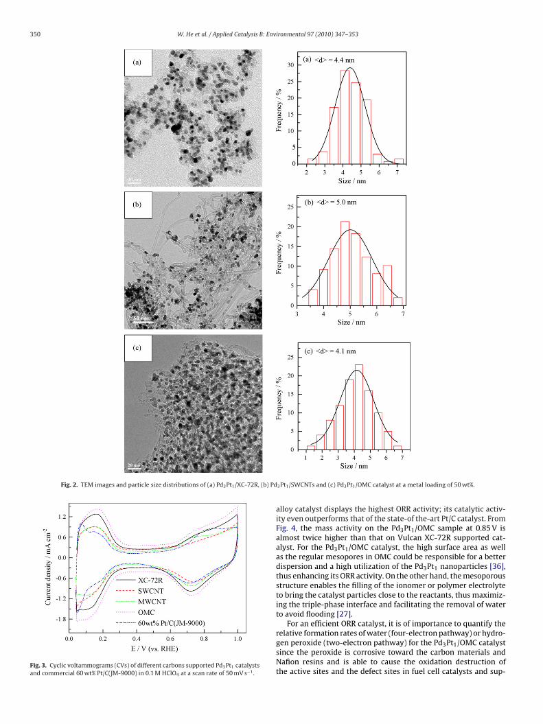
TEM micrographs of the as-prepared catalysts provide moreetails on the particle shape and size distribution of the cata-
ysts. Fig. 2 shows three typical TEM images of the Pd3Pt1/XC-72R,d3Pt1/SWCNTs and Pd3Pt1/OMC catalyst. As observed, Pd–Pt alloyarticles were well distributed onto the surface of XC-72R (Fig. 2a)nd SWCNTs bundles (Fig. 2b) with the mean particle diametersf 4.4 and 5.0 nm, respectively. These values are in fairly goodgreement with the XRD results. The TEM image in Fig. 2c showshat small Pd–Pt nanoparticles of ca. 4.1 nm are supported on theurface of the OMC particles. However, TEM images provided byne of the authors [27] for 60 wt% Pt loaded OMC in 3D revealedhat Pt particles are 3D spatially distributed in a uniform and
omogenous manner within the OMC particles. Thus, in the casef the Pd3Pt1/OMC catalyst, it is presumed that Pd–Pt alloy par-icles are supported both outside and inside the mesopores ofhe OMC; thus resulting in a highly dispersed state of the metalarticles.able 1RD and electrochemical characterizations of the Pd–Pt alloy catalysts and commercial P
Sample Size/nm SXRD/m2 g−1 ECSAH/m2 g−1
Pd3Pt1/MWCNTs 5.0 83.55 19.42Pd3Pt1/XC-72R 4.2 99.46 26.18Pd3Pt1/SWCNTs 4.9 85.26 16.06Pd3Pt1/OMC 4.0 104.44 29.01Pt/C(JM-9000) 4.5 92.83 18.46
ironmental 97 (2010) 347–353 349
3.2. Electrochemical characterizations
The electrochemical properties of Pd–Pt alloy catalystsdeposited on various carbon supports were first examined bycyclic voltammograms, as shown in Fig. 3. The stable profiles wereobtained after 15 cycles. There are three distinct potential regionsin the voltammgrams: the hydrogen adsorption/desorption regionbetween 0.05 and 0.31 V, the double-layer region between 0.31 and0.60 V, and the surface oxide formation/reduction region (>0.60 V)[32]. The change in double-layer region associated with the accessi-ble surface area of carbon is in the order: Pd3Pt1/OMC > Pd3Pt1/XC-72R > Pd3Pt1/SWCNTs > Pd3Pt1/MWCNTs, which was in the sametrend with particle size of Pd–Pt alloy catalysts on different carbonsupports. For OMC-supported catalyst with the smallest metal par-ticle size, its double-layer region is much larger than that for othercarbon-supported catalysts, probably due to the higher surface areaof the OMC. Both H region area and COad oxidation area were usedto calculate the electrochemically active surface area (ECSA) listedin Table 1. As can be seen, the ECSACO is lager than ECSAH. But bothof them are in the same trend and nearly proportional to the particlesize.
Fig. 4 presents the ORR polarization curves for Pd–Pt cata-lysts with different carbon supports in oxygen-saturated 0.1 MHClO4 at room temperature. From the figure, the ORR onall the catalysts is diffusion-controlled when the potential isless than 0.7 V and is under mixed diffusion kinetics con-trol in the potential region between 0.7 and 0.85 V. For thesake of clarity, a close-up of this region was shown in theinset of Fig. 4. Among a variety of carbon materials, theordered mesoporous carbon-supported Pd–Pt nanoparticles cat-alyst shows the highest ORR activity, and the ORR activitydecrease in the order: Pd3Pt1/OMC > Pd3Pt1/SWCNTs > Pd3Pt1/XC-72R > Pd3Pt1/MWCNTs. At a given potential of 0.85 V, forthe Pd3Pt1/MWCNTs, Pd3Pt1/XC-72R, Pd3Pt1/SWCNTs, Pt/C andPd3Pt1/OMC catalyst, the mass activities (MA) are 6.28, 8.64, 9.29,10.44 and 14.02 mA mg−1, and the specific activities (SA), a measureof the “intrinsic” kinetic performance of metal catalyst, are 27.28,26.92, 35.40, 45.59 and 34.58 �A cm−2, respectively; clearly assess-ing that the property of carbon support plays a significant role inthe improvement of ORR activity.
As mentioned above, the ORR activity on Pd3Pt1/MWCNTs isworse than that on Pd3Pt1/XC-72R. The poor dispersion of MWCNTsin EG as well as the high loading of catalyst result in the aggregatedmetal with a large particle size as shown in Table 1, which may leadto the inferior ORR activity of MWCNTs-supported Pd–Pt catalyst.Conversely, the Pd3Pt1/SWCNTs catalyst exhibits a superior ORRactivity to the Pd3Pt1/XC-72R, in spite of a similar particle size withthe Pd3Pt1/MWCNTs, probably due to high electrochemically acces-sible area and high graphitic crystallinity of the SWCNTs [33,34]. Inaddition, the limiting current density of the ORR on Pd3Pt1/SWCNTsis higher than that on the other catalysts. The thinner film electrode
of the Pd3Pt1/SWCNTs may be considered to lower the internal dif-fusion limitation of O2 [35]. It may be also related to the transportproperties of O2 within different diffusion electrodes and/or theaccessibility of different catalytic electrodes. However, the detailedreason is not well understood. Notably, the OMC-supported Pd–Ptt/C(JM-9000).
ECSACO/m2 g−1 MA at 0.85 V/mA mg−1 SACO at 0.85 V/�A cm−2
23.02 6.28 27.2832.09 8.64 26.9226.24 9.29 35.4040.54 14.02 34.5822.90 10.44 45.59
350 W. He et al. / Applied Catalysis B: Environmental 97 (2010) 347–353
Fig. 2. TEM images and particle size distributions of (a) Pd3Pt1/XC-72R, (b) Pd
Fig. 3. Cyclic voltammograms (CVs) of different carbons supported Pd3Pt1 catalystsand commercial 60 wt% Pt/C(JM-9000) in 0.1 M HClO4 at a scan rate of 50 mV s−1.
3Pt1/SWCNTs and (c) Pd3Pt1/OMC catalyst at a metal loading of 50 wt%.
alloy catalyst displays the highest ORR activity; its catalytic activ-ity even outperforms that of the state-of the-art Pt/C catalyst. FromFig. 4, the mass activity on the Pd3Pt1/OMC sample at 0.85 V isalmost twice higher than that on Vulcan XC-72R supported cat-alyst. For the Pd3Pt1/OMC catalyst, the high surface area as wellas the regular mesopores in OMC could be responsible for a betterdispersion and a high utilization of the Pd3Pt1 nanoparticles [36],thus enhancing its ORR activity. On the other hand, the mesoporousstructure enables the filling of the ionomer or polymer electrolyteto bring the catalyst particles close to the reactants, thus maximiz-ing the triple-phase interface and facilitating the removal of waterto avoid flooding [27].
For an efficient ORR catalyst, it is of importance to quantify the
relative formation rates of water (four-electron pathway) or hydro-gen peroxide (two-electron pathway) for the Pd3Pt1/OMC catalystsince the peroxide is corrosive toward the carbon materials andNafion resins and is able to cause the oxidation destruction ofthe active sites and the defect sites in fuel cell catalysts and sup-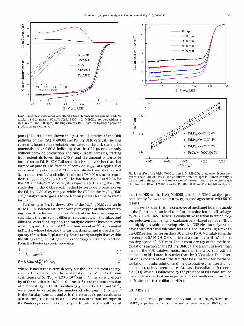
W. He et al. / Applied Catalysis B: Environmental 97 (2010) 347–353 351
FcOp
ppcpwfffc(ttstaf
0iedriqtF
B
waciowi(t
ig. 4. Linear scan voltammograms (LSVs) of the different carbons supported Pd3Pt1
atalysts and commercial 60 wt% Pt/C(JM-9000) in 0.1 M HClO4 saturated with pure2 (5 mV s−1 and 1600 rpm). The ring currents, RRDE data, for hydrogen peroxideroduction are contrasted.
orts [37]. RRDE data shown in Fig. 4 are illustrative of the ORRathway on the Pt/C(JM-9000) and Pd3Pt1/OMC catalyst. The ringurrent is found to be negligible compared to the disk current forotentials above 0.80 V, indicating that the ORR proceeds nearlyithout peroxide production. The ring current increases, starting
rom potentials lower than 0.75 V, and the amount of peroxideormed on the Pd3Pt1/OMC alloy catalyst is slightly higher than thatormed on pure Pt. The fraction of peroxide, XH2O2 , at a typical fuelell operating potential of 0.70 V, was evaluated from disk currentID), ring current (IR) and collection factor (N = 0.20) using the equa-ion: XH2O2 = 2IR/N/(ID + IR/N). The fractions are 1.1 and 2.3% forhe Pt/C and Pd3Pt1/OMC catalysts, respectively. Thereby, the RRDEtudy during the ORR reveals negligible peroxide production onhe Pd3Pt1/OMC alloy catalyst, while the ORR on the Pd3Pt1/OMClloy catalyst undergoes a four-electron process leading to waterormation.
Furthermore, Fig. 5a shows LSVs of the Pd3Pt1/OMC catalyst in.1 M HClO4 solution saturated with pure oxygen at different rotat-
ng rates. It can be seen that the ORR activity in the kinetic region isssentially the same at the different rotating rates. In the mixed andiffusion-controlled regions, the catalytic current increases withotating speed. The plot of I−1 as a function of ω−1/2 is presentedn Fig. 5b, where I denotes the current density, and ω angular fre-uency of rotation. All plots in Fig. 5b are nearly straight lines withinhe fitting error, indicating a first-order oxygen reduction reaction.rom the Koutecky–Levich equation
1I
= 1Ik
+ 1Bω1/2
(1)
= 0.62nFAD2/3O2
�1/6CO2 (2)
here I is measured current density, Ik is the kinetic current density,nd ω is the rotation rate. The published values [32,38] of diffusionoefficience of O2 (DO2 = 1.93 × 10⁻⁵ cm2 s−1), the kinetic viscos-ty of the solution (� = 8.93 × 10⁻³ cm2 s−1), and the concentration
f dissolved O2 in HClO4 solution (CO2 = 1.18 × 10⁻⁶ mol cm−1)ere used to calculate the number of electrons (n), where Fs the Faraday constant and A is the electrode’s geometric area0.0707 cm2). The constant B value was obtained from the slopes ofhe Koutecky–Levich plots. Subsequently, calculated results reveal
Fig. 5. (a) LSVs of the Pd3Pt1/OMC catalyst in 0.1 M HClO4 saturated with pure oxy-gen at a scan rate of 5 mV s−1and at different rotation speeds. Current density isnormalized to the geometrical surface area of the electrode. (b) Koutechy–Levichplots for the ORR in 0.1 M HClO4 on the Pt/C(JM-9000) and Pd3Pt1/OMC catalysts.
that the ORR on the Pt/C(JM-9000) and Pd–Pt/OMC catalyst pre-dominantly follows a 4e− pathway, in good agreement with RRDEresults.
It is well known that the crossover of methanol from the anodeto the Pt cathode can lead to a further reduction in cell voltage,by ca. 200–300 mV. There is a competitive reaction between oxy-gen reduction and methanol oxidation on Pt-based cathodes. Thus,it is highly desirable to develop selective-ORR electrocatalysts thathave a high methanol tolerance for DMFC applications. Fig. 6 revealsthe ORR performances on the Pt/C and Pd3Pt1/OMC catalysts in thepresence of 0.5 M CH3OH solution at a scan rate of 5 mV s−1 androtating speed of 1600 rpm. The current density of the methanoloxidation reaction on the Pd3Pt1/OMC catalysts is much lower thanthat on the Pt/C catalyst, indicating that the alloy catalysts formethanol oxidation are less active than the Pt/C catalyst. This obser-vation is consistent with the fact that Pd is inactive for methanoloxidation in acidic solution and the dissociative chemisorption ofmethanol requires the existence of at least three adjacent Pt ensem-bles [39], which is influenced by the presence of Pd atoms aroundthe Pt active sites that are expected to block methanol adsorptionon Pt sites due to the dilution effect.
3.3. MEA test
To explore the possible application of the Pd3Pt1/OMC in aDMFC, a performance comparison of two passive DMFCs with

352 W. He et al. / Applied Catalysis B: Env
FC
OttaotpPptsdrtrOetDtectO
FPt
[
[
[
[
ig. 6. LSVs of the Pt/C(JM-9000) and Pd3Pt1/OMC catalysts in 0.1 M HClO4 + 0.5 MH3OH solution saturated with pure O2 at 5 mV s−1 and 1600 rpm.
MC-supported Pd–Pt alloy and commercial Pt/C(JM-9000) ashe cathode catalysts is shown in Fig. 7. It can be seen thathe open circuit voltage of the passive DMFC using Pd3Pt1/OMCs cathode catalyst is slightly higher than that with Pt/C cath-de. Less methanol crossover from the anode to the cathode athe beginning may be the reason to underestimate the methanoloisoning effect on the Pt catalyst. Importantly, the as-preparedd3Pt1/OMC catalyst exhibited a better performance with lowolarization losses at both low and high current densities thanhe Pt/C catalyst. When using 3 M methanol solution, the pas-ive DMFC consisting of the Pd3Pt1/OMC as the cathode catalystelivers the enhanced peak power density of 25.3 mW cm−2 withespect to the peak power density of 21.8 mW cm−2 observed forhe DMFC with Pt/C cathode, which is consistent with the LSVesults that the Pd3Pt1/OMC exhibits a better methanol-tolerantRR activity than the Pt/C. To further identify the methanol tol-rance of the Pd3Pt1/OMC, 5 M methanol solution was used forwo passive DMFCs. The maximal power density of the passiveMFC using Pd3Pt1/OMC cathode decreases to 23.8 mW cm−2, due
o an increased crossover at high methanol concentration. How-ver, the maximal power density of the passive DMFC using Pt/C
atalyst decreases to ca. 17.1 mW cm−2. These results again assesshat the Pd3Pt1/OMC exhibits a high methanol tolerance during theRR.ig. 7. Polarization curves of two passive DMFCs with the Pt/C(JM-9000) andd3Pt1/OMC as cathode catalysts operated at 3 and 5 M methanol solution, respec-ively.
[[
[[
[[[
[
[
[
[[
[
[[[
[
[
[
[
ironmental 97 (2010) 347–353
4. Conclusions
A variety of carbon materials were used to support the Pd–Ptalloy nanoparticles with a Pd/Pt atomic ratio of 3:1, whose struc-tures and catalytic activities were characterized by XRD, TEM andRDE/RRDE techniques. It is remarkable that the OMC-supportedPd3Pt1 catalyst exhibits the highest mass activity for the ORRamong the investigated carbon supports. The high ORR activity aswell as good tolerance to methanol on the Pd3Pt1/OMC alloy cata-lyst suggests that the Pd3Pt1/OMC may be an economically viablecandidate to replace Pt as a cathode catalyst in a DMFC.
Acknowledgements
The authors would like to thank the NSF of China (20673136and 20706056), the National “863” High-Technology ResearchPrograms of China (2007AA05Z107, 2006AA05Z136 and2008AA05Z102), the 100 People Plan Program of the CAS andthe Knowledge Innovation Engineering of the CAS for supportof this work. W.H. also thanks the Graduate Student InnovationFoundation of Jiangsu Province (CX09B 076Z).
References
[1] J.L. Zhang, M.B. Vukmirovic, K. Sasaki, A.U. Nilekar, M. Mavrikakis, R.R. Adzic, J.Am. Chem. Soc. 127 (2005) 12480–12481.
[2] D.R. Rolison, P.L. Hagans, K.E. Swider, J.W. Long, Langmuir 15 (1999) 774–779.[3] J.J. Wang, G.P. Yin, G.J. Wang, Z.B. Wang, Y.Z. Gao, Electrochem. Commun. 10
(2008) 831–834.[4] A. Sarkar, A.V. Murugan, A. Manthiram, J. Phys. Chem. C 112 (2008)
12037–12043.[5] W.E. Mustain, K. Kepler, J. Prakash, Electrochem. Commun. 8 (2006) 406–410.[6] A. Sarkar, A.V. Murugan, A. Manthiram, J. Mater. Chem. 19 (2009) 159–165.[7] W.M. Wang, Q.H. Huang, J.Y. Liu, Z.Q. Zou, M.Y. Zhao, W. Vogel, H. Yang, J. Catal.
266 (2009) 156–163.[8] W. He, J.Y. Liu, Y.J. Qiao, Z.Q. Zou, X.G. Zhang, D.L. Akins, H. Yang, J. Power Sources
195 (2010) 1046–1050.[9] H. Liu, W. Li, A. Manthiram, Appl. Catal. B: Environ. 90 (2009) 184–194.10] Y.H. Cho, B. Choi, Y.H. Cho, H.S. Park, Y.E. Sung, Electrochem. Commun. 9 (2007)
378–381.11] H.Q. Li, G.Q. Sun, N. Li, S.G. Sun, D.S. Su, Q. Xin, J. Phys. Chem. C 111 (2007)
5605–5617.12] J.B. Joo, Y.J. Kim, W. Kim, N.D. Kim, P. Kim, Y. Kim, J. Yi, Korean J. Chem. Eng. 25
(2008) 770–774.13] D. Mirabile Gattia, M.V. Antisari, L. Giorgi, R. Marazzi, E. Piscopiello, A. Montone,
S. Bellitto, S. Licoccia, E. Traversa, J. Power Sources 194 (2009) 243–251.14] E. Antolini, Appl. Catal. B: Environ. 88 (2009) 1–24.15] W.Z. Li, C.H. Liang, W.J. Zhou, J.S. Qiu, Z.H. Zhou, G.Q. Sun, Q. Xin, J. Phys. Chem.
B 107 (2003) 6292–6299.16] Z.Q. Liu, J. Ma, Y.H. Cui, B.P. Zhang, Appl. Catal. B: Environ. 92 (2009) 301–306.17] F. Alcaide, G. Alvarez, O. Miguel, M. Jesus Lazaro, R. Moliner, A. Lopez-Cudero, J.
Solla-Gullon, E. Herrero, A. Aldaz, Electrochem. Commun. 11 (2009) 1081–1084.18] R. Ryoo, S.H. Joo, M. Kruk, M. Jaroniec, Adv. Mater. 13 (2001) 677–681.19] J. Ding, K. Chan, J. Ren, F. Xiao, Electrochim. Acta 50 (2005) 3131–3141.20] A. Hayashi, H. Notsu, K. Kimijima, J. Miyamoto, I. Yagi, Electrochim. Acta 53
(2008) 6117–6125.21] S.H. Joo, K. Kwon, D.J. You, C. Pak, H. Chang, J.M. Kim, Electrochim. Acta 54
(2009) 5746–5753.22] S.H. Joo, S.J. Choi, I. Oh, J. Kwak, Z. Liu, O. Terasaki, R. Ryoo, Nature 412 (2001)
169–172.23] S. Vengatesan, H.J. Kim, S.K. Kim, I.H. Oh, S.Y. Lee, E. Cho, H.Y. Ha, T.H. Lim,
Electrochim. Acta 54 (2008) 856–861.24] G. Wu, D.Y. Li, C.S. Dai, D.L. Wang, N. Li, Langmuir 24 (2008) 3566–3575.25] W.M. Wang, Q.H. Huang, J.Y. Liu, Z.Q. Zou, Z.L. Li, H. Yang, Electrochem. Com-
mun. 10 (2008) 1396–1399.26] S.H. Joo, C. Pak, D.J. You, S. Lee, H.I. Lee, J.M. Kim, H. Chang, D. Seung, Electrochim.
Acta 52 (2006) 1618–1626.27] H. Chang, S.H. Joo, C. Pak, J. Mater. Chem. 17 (2007) 3078–3088.28] H. Meng, S. Sun, J. Masse, J. Dodelet, Chem. Mater. 20 (2008) 6998–7002.29] T. Yuan, Z.Q. Zou, M. Chen, Z.L. Li, B.J. Xia, H. Yang, J. Power Sources 192 (2009)
423–428.30] A.E. Cordero-Borboa, E. Sterling-Black, A. Gomez-Cortes, A. Vazquez-Zavala,
Appl. Surf. Sci. 220 (2003) 169–174.31] K.D. Beard, J.W. Van Zee, J.R. Monnier, Appl. Catal. B: Environ. 88 (2009)
185–193.32] J.H. Yang, J.Y. Lee, Q.B. Zhang, W.J. Zhou, Z.L. Liu, J. Electrochem. Soc. 155 (2008)
B776–B781.33] G. Wu, B.Q. Xu, J. Power Sources 174 (2007) 148–158.

[
[[
W. He et al. / Applied Catalysis B: Env
34] A. Kongkanand, K. Vinodgopal, S. Kuwabata, P.V. Kamat, J. Phys. Chem. B 110(2006) 16185–16188.
35] Y.H. Shih, G.V. Sagar, S.D. Lin, J. Phys. Chem. C 112 (2008) 123–130.36] V. Raghuveer, A. Manthiram, J. Electrochem. Soc. 152 (2005) A1504–A1510.
[[
[
ironmental 97 (2010) 347–353 353
37] X.G. Li, S. Park, B.N. Popov, J. Power Sources 195 (2010) 445–452.38] W.M. Wang, D. Zheng, C. Du, Z.Q. Zou, X.G. Zhang, B.J. Xia, H. Yang, D.L. Akins,
J. Power Sources 167 (2007) 243–249.39] J. Salgado, E. Antolini, E.R. Gonzalez, Appl. Catal. B: Environ. 57 (2005) 283–290.