Embed Size (px)
Citation preview
SS2100 H2S Analyzer
Hardware Installation and MaintenanceManual
Hardware Installation and MaintenanceManual
P/N 4900002060 rev C
OXY4400 Oxygen AnalyzerOperator’s Manual


OXY4400 Oxygen Analyzer
Operator’s Manual
Use this manual with theOxyview Firmware CD
Products of
4333 W Sam Houston Pkwy N, Suite 100Houston, TX 77043-1223
Tel: 800.619.2861Fax: 713.856.6623
www.spectrasensors.com
Copyright © 2015 SpectraSensors, Inc. No part of this manual may be reproduced inwhole or in part without the express written permission of SpectraSensors, Inc.SpectraSensors reserves the right to change product design and specifications at anytime without prior notice.
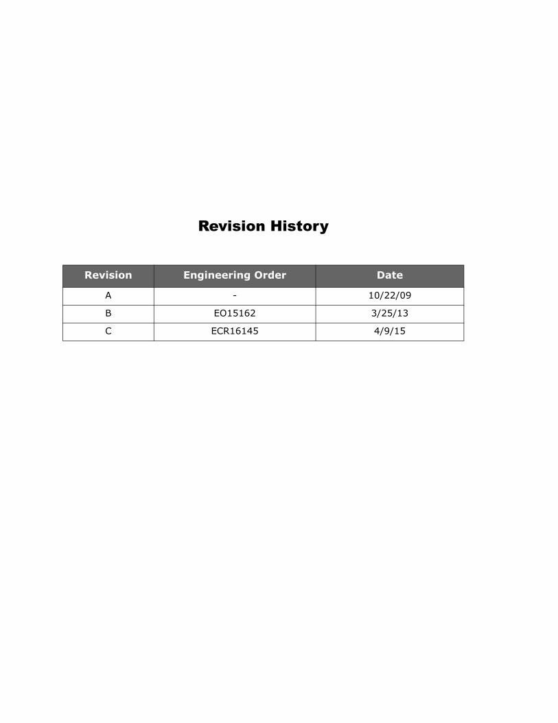
Revision History
Revision Engineering Order Date
A - 10/22/09
B EO15162 3/25/13
C ECR16145 4/9/15
TABLE OF CONTENTS
List of Figures . . . . . . . . . . . . . . . . . . . . . . . . . . . . . . . . . . . . . . . . . . . . . . .v
List of Tables . . . . . . . . . . . . . . . . . . . . . . . . . . . . . . . . . . . . . . . . . . . . . . . vii
1: Introduction Who Should Read This Manual . . . . . . . . . . . . . . . . . . . . . . . . . . . . . . . . . . . . 1-1How to Use This Manual. . . . . . . . . . . . . . . . . . . . . . . . . . . . . . . . . . . . . . . . . 1-1
General Warnings and Cautions . . . . . . . . . . . . . . . . . . . . . . . . . . . . . . . . . 1-1Conventions Used in this Manual . . . . . . . . . . . . . . . . . . . . . . . . . . . . . . . . 1-2
SpectraSensors Overview . . . . . . . . . . . . . . . . . . . . . . . . . . . . . . . . . . . . . . . 1-2About the OXY4400 Analyzer . . . . . . . . . . . . . . . . . . . . . . . . . . . . . . . . . . . . . 1-2
Sensor Characteristics of Oxygen-Sensitive Sensors . . . . . . . . . . . . . . . . . . 1-2Temperature . . . . . . . . . . . . . . . . . . . . . . . . . . . . . . . . . . . . . . . . . . . . . . 1-3Cross-sensitivity . . . . . . . . . . . . . . . . . . . . . . . . . . . . . . . . . . . . . . . . . . . 1-3Response Time . . . . . . . . . . . . . . . . . . . . . . . . . . . . . . . . . . . . . . . . . . . . 1-3Housing for Oxygen in Natural Gas (DP-BOS3-L5-ST5-NOP) . . . . . . . . . . . . . 1-4Trace Oxygen Probe . . . . . . . . . . . . . . . . . . . . . . . . . . . . . . . . . . . . . . . . . 1-4
Schematic drawing for the Trace Oxygen Probe . . . . . . . . . . . . . . . . . . . 1-5Safety Guidelines . . . . . . . . . . . . . . . . . . . . . . . . . . . . . . . . . . . . . . . . . . . . . 1-5Getting Familiar with the Analyzer . . . . . . . . . . . . . . . . . . . . . . . . . . . . . . . . . 1-6
Required Basic Equipment. . . . . . . . . . . . . . . . . . . . . . . . . . . . . . . . . . . . . 1-7
2: Installation What Should be Included in the Shipping Box . . . . . . . . . . . . . . . . . . . . . . . . . 2-1Inspecting the Analyzer . . . . . . . . . . . . . . . . . . . . . . . . . . . . . . . . . . . . . . . . . 2-1Installing the Analyzer. . . . . . . . . . . . . . . . . . . . . . . . . . . . . . . . . . . . . . . . . . 2-1Hardware and Tools for Installation. . . . . . . . . . . . . . . . . . . . . . . . . . . . . . . . . 2-2
Hardware . . . . . . . . . . . . . . . . . . . . . . . . . . . . . . . . . . . . . . . . . . . . . . . . 2-2Tools . . . . . . . . . . . . . . . . . . . . . . . . . . . . . . . . . . . . . . . . . . . . . . . . . . . 2-2
Mounting the Analyzer. . . . . . . . . . . . . . . . . . . . . . . . . . . . . . . . . . . . . . . . . . 2-2To mount the analyzer . . . . . . . . . . . . . . . . . . . . . . . . . . . . . . . . . . . . . . . 2-3
Connecting Electrical Power to the Analyzer . . . . . . . . . . . . . . . . . . . . . . . . . . . 2-3To connect electrical power to the analyzer. . . . . . . . . . . . . . . . . . . . . . . . . 2-4
Connecting Electrical Power to the Enclosure Heater . . . . . . . . . . . . . . . . . . . . . 2-5To connect electrical power to the enclosure heater . . . . . . . . . . . . . . . . . . . 2-5
Connecting the Analog Outputs/Analog Inputs . . . . . . . . . . . . . . . . . . . . . . . . . 2-6To connect the analog outputs/analog inputs . . . . . . . . . . . . . . . . . . . . . . . 2-7
Connecting the Gas Lines . . . . . . . . . . . . . . . . . . . . . . . . . . . . . . . . . . . . . . . 2-7To connect the sample supply line . . . . . . . . . . . . . . . . . . . . . . . . . . . . . . . 2-8To connect the sample bypass/sample return . . . . . . . . . . . . . . . . . . . . . . . 2-8
Installing the Temperature (RTD) Probe . . . . . . . . . . . . . . . . . . . . . . . . . . . . . 2-9Installing the Oxygen Probe . . . . . . . . . . . . . . . . . . . . . . . . . . . . . . . . . . . . . 2-10Connecting the Calibration Gas (Optional) . . . . . . . . . . . . . . . . . . . . . . . . . . . 2-14Conditioning the SCS Tubing . . . . . . . . . . . . . . . . . . . . . . . . . . . . . . . . . . . . 2-14
3: Sample Conditioning System (SCS) Operation About the SCS . . . . . . . . . . . . . . . . . . . . . . . . . . . . . . . . . . . . . . . . . . . . . . . 3-1Checking the SCS Installation. . . . . . . . . . . . . . . . . . . . . . . . . . . . . . . . . . . . . 3-2
To perform SCS installation checks . . . . . . . . . . . . . . . . . . . . . . . . . . . . . . 3-2Starting up the SCS . . . . . . . . . . . . . . . . . . . . . . . . . . . . . . . . . . . . . . . . . . . 3-2
To prepare for SCS startup . . . . . . . . . . . . . . . . . . . . . . . . . . . . . . . . . . . . 3-2To start up the sample bypass stream on process sample. . . . . . . . . . . . . . . 3-2
OXY4400 Operator’s Manual i
Oxygen Analyzer
To start up the analyzer on process sample . . . . . . . . . . . . . . . . . . . . . . . . 3-3Shutting Down the SCS . . . . . . . . . . . . . . . . . . . . . . . . . . . . . . . . . . . . . . . . 3-3
4: Configuration Powering up the Instrument . . . . . . . . . . . . . . . . . . . . . . . . . . . . . . . . . . . . . . 4-1Menu Selection . . . . . . . . . . . . . . . . . . . . . . . . . . . . . . . . . . . . . . . . . . . . . . . 4-2Pre-Calibration Procedure . . . . . . . . . . . . . . . . . . . . . . . . . . . . . . . . . . . . . . . 4-3
Sensor Type . . . . . . . . . . . . . . . . . . . . . . . . . . . . . . . . . . . . . . . . . . . . . . 4-3Sensor Constants. . . . . . . . . . . . . . . . . . . . . . . . . . . . . . . . . . . . . . . . . . . 4-5
Measurement . . . . . . . . . . . . . . . . . . . . . . . . . . . . . . . . . . . . . . . . . . . . . . . . 4-6Sampling Rate . . . . . . . . . . . . . . . . . . . . . . . . . . . . . . . . . . . . . . . . . . . . . 4-6Temperature . . . . . . . . . . . . . . . . . . . . . . . . . . . . . . . . . . . . . . . . . . . . . . 4-6Sensor Protect. . . . . . . . . . . . . . . . . . . . . . . . . . . . . . . . . . . . . . . . . . . . . 4-8Signal Averaging . . . . . . . . . . . . . . . . . . . . . . . . . . . . . . . . . . . . . . . . . . . 4-8Oxygen Unit . . . . . . . . . . . . . . . . . . . . . . . . . . . . . . . . . . . . . . . . . . . . . . 4-8Signal Intensity . . . . . . . . . . . . . . . . . . . . . . . . . . . . . . . . . . . . . . . . . . . . 4-9
Calibration . . . . . . . . . . . . . . . . . . . . . . . . . . . . . . . . . . . . . . . . . . . . . . . . . . 4-9Status . . . . . . . . . . . . . . . . . . . . . . . . . . . . . . . . . . . . . . . . . . . . . . . . . 4-10Calibrate. . . . . . . . . . . . . . . . . . . . . . . . . . . . . . . . . . . . . . . . . . . . . . . . 4-10
Calibration of the oxygen sensor with Temperature compensation(Preferred Method) . . . . . . . . . . . . . . . . . . . . . . . . . . . . . . . . . 4-11
Calibration of the oxygen sensor without Temperature compensation . . . 4-14Calibration of the oxygen sensor with Manual Temperature compensation 4-15
Data Logging . . . . . . . . . . . . . . . . . . . . . . . . . . . . . . . . . . . . . . . . . . . . . . . 4-17Configuration . . . . . . . . . . . . . . . . . . . . . . . . . . . . . . . . . . . . . . . . . . . . . . . 4-18
Status . . . . . . . . . . . . . . . . . . . . . . . . . . . . . . . . . . . . . . . . . . . . . . . . . 4-18Analog Out . . . . . . . . . . . . . . . . . . . . . . . . . . . . . . . . . . . . . . . . . . . . . . 4-18Analog In . . . . . . . . . . . . . . . . . . . . . . . . . . . . . . . . . . . . . . . . . . . . . . . 4-20Clock/Date . . . . . . . . . . . . . . . . . . . . . . . . . . . . . . . . . . . . . . . . . . . . . . 4-21Display . . . . . . . . . . . . . . . . . . . . . . . . . . . . . . . . . . . . . . . . . . . . . . . . . 4-21Reset Config.. . . . . . . . . . . . . . . . . . . . . . . . . . . . . . . . . . . . . . . . . . . . . 4-21
Diag & Test . . . . . . . . . . . . . . . . . . . . . . . . . . . . . . . . . . . . . . . . . . . . . . . . 4-21System. . . . . . . . . . . . . . . . . . . . . . . . . . . . . . . . . . . . . . . . . . . . . . . . . 4-22Outputs . . . . . . . . . . . . . . . . . . . . . . . . . . . . . . . . . . . . . . . . . . . . . . . . 4-22Inputs . . . . . . . . . . . . . . . . . . . . . . . . . . . . . . . . . . . . . . . . . . . . . . . . . 4-22
5: PC OperationsInstalling the Software . . . . . . . . . . . . . . . . . . . . . . . . . . . . . . . . . . . . . . . . . 5-1Function and Description . . . . . . . . . . . . . . . . . . . . . . . . . . . . . . . . . . . . . . . . 5-2
Menu Bar . . . . . . . . . . . . . . . . . . . . . . . . . . . . . . . . . . . . . . . . . . . . . . . . 5-3Menu Bar Definitions . . . . . . . . . . . . . . . . . . . . . . . . . . . . . . . . . . . . . . 5-4
Control Bar . . . . . . . . . . . . . . . . . . . . . . . . . . . . . . . . . . . . . . . . . . . . . . . 5-5Control Buttons . . . . . . . . . . . . . . . . . . . . . . . . . . . . . . . . . . . . . . . . . . . . 5-5
Measurement Assistant . . . . . . . . . . . . . . . . . . . . . . . . . . . . . . . . . . . . 5-6Calibration Assistant . . . . . . . . . . . . . . . . . . . . . . . . . . . . . . . . . . . . . . 5-7Data Logging . . . . . . . . . . . . . . . . . . . . . . . . . . . . . . . . . . . . . . . . . . . 5-7
Settings . . . . . . . . . . . . . . . . . . . . . . . . . . . . . . . . . . . . . . . . . . . . . . . . . 5-8Instrument Info . . . . . . . . . . . . . . . . . . . . . . . . . . . . . . . . . . . . . . . . . 5-8Analog Output . . . . . . . . . . . . . . . . . . . . . . . . . . . . . . . . . . . . . . . . . . 5-8Analog Input . . . . . . . . . . . . . . . . . . . . . . . . . . . . . . . . . . . . . . . . . . . 5-9LED Intensity . . . . . . . . . . . . . . . . . . . . . . . . . . . . . . . . . . . . . . . . . . 5-10Oxygen Unit . . . . . . . . . . . . . . . . . . . . . . . . . . . . . . . . . . . . . . . . . . . 5-12
Warning Lights . . . . . . . . . . . . . . . . . . . . . . . . . . . . . . . . . . . . . . . . . . . 5-13Graphical Display Window. . . . . . . . . . . . . . . . . . . . . . . . . . . . . . . . . . . . 5-14
Zoom function . . . . . . . . . . . . . . . . . . . . . . . . . . . . . . . . . . . . . . . . . 5-14Status Bar . . . . . . . . . . . . . . . . . . . . . . . . . . . . . . . . . . . . . . . . . . . . 5-14
ii 4900002060 rev. C 4-9-15
Table of Contents
Appendix A: Specifications Technical Notes . . . . . . . . . . . . . . . . . . . . . . . . . . . . . . . . . . . . . . . . . . . . . . A-2Spare Parts . . . . . . . . . . . . . . . . . . . . . . . . . . . . . . . . . . . . . . . . . . . . . . . . A-13
Appendix B: Troubleshooting Error Codes . . . . . . . . . . . . . . . . . . . . . . . . . . . . . . . . . . . . . . . . . . . . . . . . . B-2
Decoding example . . . . . . . . . . . . . . . . . . . . . . . . . . . . . . . . . . . . . . . . . . B-2Recommendations for Correct Measurement . . . . . . . . . . . . . . . . . . . . . . . . . . B-2
Signal Drifts due to Oxygen Gradients . . . . . . . . . . . . . . . . . . . . . . . . . . . . B-3Signal Drifts due to Temperature Gradients . . . . . . . . . . . . . . . . . . . . . . . . B-3Signal Drift due to Photo-decomposition . . . . . . . . . . . . . . . . . . . . . . . . . . . B-3Signal Drift due to Too Much Ambient Light. . . . . . . . . . . . . . . . . . . . . . . . . B-3
Oxygen Conversion Formula. . . . . . . . . . . . . . . . . . . . . . . . . . . . . . . . . . . . . . B-4Sensor Safety. . . . . . . . . . . . . . . . . . . . . . . . . . . . . . . . . . . . . . . . . . . . . . . . B-4Performance Improvement. . . . . . . . . . . . . . . . . . . . . . . . . . . . . . . . . . . . . . . B-4
Replacing the Oxygen Probe . . . . . . . . . . . . . . . . . . . . . . . . . . . . . . . . . . . B-5To replace the OXY4400 probe: . . . . . . . . . . . . . . . . . . . . . . . . . . . . . . . . . B-5
Periodic SCS Maintenance . . . . . . . . . . . . . . . . . . . . . . . . . . . . . . . . . . . . . . . B-6Regular SCS Status Check . . . . . . . . . . . . . . . . . . . . . . . . . . . . . . . . . . . . B-7To check filters . . . . . . . . . . . . . . . . . . . . . . . . . . . . . . . . . . . . . . . . . . . . B-7
Service Contact . . . . . . . . . . . . . . . . . . . . . . . . . . . . . . . . . . . . . . . . . . . . . . B-7Customer Service. . . . . . . . . . . . . . . . . . . . . . . . . . . . . . . . . . . . . . . . . . B-7Return Material Authorization . . . . . . . . . . . . . . . . . . . . . . . . . . . . . . . . . . B-8
Packing and Storage . . . . . . . . . . . . . . . . . . . . . . . . . . . . . . . . . . . . . . . . . . . B-8To prepare the analyzer for shipment or storage . . . . . . . . . . . . . . . . . . . . . B-8Storage . . . . . . . . . . . . . . . . . . . . . . . . . . . . . . . . . . . . . . . . . . . . . . . . . B-9
Disclaimers . . . . . . . . . . . . . . . . . . . . . . . . . . . . . . . . . . . . . . . . . . . . . . . . . B-9
Index . . . . . . . . . . . . . . . . . . . . . . . . . . . . . . . . . . . . . . . . . . . . . . . . . Index-1
4900002060 rev. C 4-9-15 iii

Oxygen Analyzer
THIS PAGE INTENTIONALLY LEFT BLANK
iv 4900002060 rev. C 4-9-15
LIST OF FIGURES
Figure 1–1. Response of the BOS3 sensor toward changes in theoxygen concentration . . . . . . . . . . . . . . . . . . . . . . . . . . . . . . . . 1-3
Figure 1–2. Standard fiber-optic oxygen sensors fittings. . . . . . . . . . . . . . . . . 1-4Figure 1–3. Trace oxygen probe . . . . . . . . . . . . . . . . . . . . . . . . . . . . . . . . . 1-4Figure 1–4. Trace oxygen probe schematic . . . . . . . . . . . . . . . . . . . . . . . . . . 1-5Figure 1–5. OXY4400 analyzer . . . . . . . . . . . . . . . . . . . . . . . . . . . . . . . . . . 1-7
Figure 2–1. RTD probe terminal connection. . . . . . . . . . . . . . . . . . . . . . . . . . 2-9Figure 2–2. RTD probe installed. . . . . . . . . . . . . . . . . . . . . . . . . . . . . . . . . 2-10Figure 2–3. Removing protective plunger from oxygen probe . . . . . . . . . . . . 2-11Figure 2–4. Inserting the oxygen probe into the OXY4400 . . . . . . . . . . . . . . 2-12Figure 2–5. Oxygen probe installed . . . . . . . . . . . . . . . . . . . . . . . . . . . . . . 2-13
Figure 4–1. Analyzer LCD display. . . . . . . . . . . . . . . . . . . . . . . . . . . . . . . . . 4-1Figure 4–2. Main display view . . . . . . . . . . . . . . . . . . . . . . . . . . . . . . . . . . . 4-2Figure 4–3. Alternate display view . . . . . . . . . . . . . . . . . . . . . . . . . . . . . . . . 4-2Figure 4–4. Main menu. . . . . . . . . . . . . . . . . . . . . . . . . . . . . . . . . . . . . . . . 4-3Figure 4–6. Configuration menu . . . . . . . . . . . . . . . . . . . . . . . . . . . . . . . . 4-18Figure 4–7. Analog Out: select Output menu. . . . . . . . . . . . . . . . . . . . . . . . 4-19Figure 4–8. Diagnostic and test menu . . . . . . . . . . . . . . . . . . . . . . . . . . . . 4-21
Figure 5–1. OXY4400 Main window . . . . . . . . . . . . . . . . . . . . . . . . . . . . . . . 5-3Figure 5–2. Control bar . . . . . . . . . . . . . . . . . . . . . . . . . . . . . . . . . . . . . . . 5-5Figure 5–3. Measurement assistant . . . . . . . . . . . . . . . . . . . . . . . . . . . . . . . 5-6Figure 5–4. Instrument info display . . . . . . . . . . . . . . . . . . . . . . . . . . . . . . . 5-8Figure 5–5. Analog Output choice . . . . . . . . . . . . . . . . . . . . . . . . . . . . . . . . 5-9Figure 5–6. Analog Input configuration. . . . . . . . . . . . . . . . . . . . . . . . . . . . 5-10
Figure A–1. Outline and mounting dimensions - panel mount . . . . . . . . . . . . . A-4Figure A–2. Sample system schematic - panel mount. . . . . . . . . . . . . . . . . . . A-5Figure A–3. Power and signal wiring diagram - panel mount . . . . . . . . . . . . . . A-6Figure A–4. Outline and mounting dimensions - Unheated
enclosure mounted . . . . . . . . . . . . . . . . . . . . . . . . . . . . . . . . . . A-7Figure A–5. Sample system schmatic - Unheated enclosure mounted . . . . . . . A-8Figure A–6. Power and signal wiring diagram - Unheated
enclosure mounted . . . . . . . . . . . . . . . . . . . . . . . . . . . . . . . . . . A-9Figure A–7. Outline and mounting dimension - Heated enclosure mounted . . A-10Figure A–8. Sample system schematic - Heated enclosure mounted . . . . . . . A-11Figure A–9. Power and signal wiring diagram - Unheated
enclosure mounted . . . . . . . . . . . . . . . . . . . . . . . . . . . . . . . . . A-12
OXY4400 Operator’s Manual v

Oxygen Analyzer
THIS PAGE INTENTIONALLY LEFT BLANK
vi 4900002060 rev. C 4-9-15
LIST OF TABLES
Table 2–1. Terminal layout and description . . . . . . . . . . . . . . . . . . . . . . . . . 2-5
Table 4–1. Default sensor constants . . . . . . . . . . . . . . . . . . . . . . . . . . . . . . 4-6
Table A-1. OXY4400 analyzer specifications. . . . . . . . . . . . . . . . . . . . . . . . . A-1Table A–2. Replacement parts for OXY4400 analyzer . . . . . . . . . . . . . . . . . A-13
Table B–1. Potential instrument problems and their solutions. . . . . . . . . . . . . B-1Table B–2. Error value definitions . . . . . . . . . . . . . . . . . . . . . . . . . . . . . . . . B-2Table B–3. Sensor drift at 0% air saturation (0 ppb)
recording 3600, 50000 and 100000 data points . . . . . . . . . . . . . . B-3
OXY4400 Operator’s Manual vii

Oxygen Analyzer
THIS PAGE INTENTIONALLY LEFT BLANK
viii 4900002060 rev. C 4-9-15
1 - INTRODUCTION
SpectraSensors’ OXY4400 product is a stand-alone fiber optic oxygen meter based on fluorescence quenching technology that creates very stable, internally referenced measured values. This technology enables a more flexible use of oxygen sensors (also called optodes) in a variety of sensor fittings, if required.
Who Should Read This ManualThis manual should be read and referenced by anyone installing, operating or having direct contact with the analyzer.
How to Use This ManualTake a moment to familiarize yourself with this Operator’s Manual by reading the "Table of Contents".
There are a number of options and accessories available for the OXY4400 analyzers. This manual has been written to address the most common options and accessories. Images, tables and charts have been included to provide a visual understanding of the analyzer and its functions. Special symbols are also used to provide the user with key information regarding the system configuration and/or operation. Pay close attention to this information.
General Warnings and Cautions
Instructional icons are provided in this manual to alert the user of potential hazards, important information and valuable tips. Following are the symbols and associated warning and caution types to observe when servicing the analyzer.
General notes and important information concerning the installation and operation of the analyzer.
Warning statement for hazardous voltage. Contact may cause electric shock or burn. Turn off and lock out system before servicing.
Failure to follow all directions may result in damage or malfunction of the analyzer.
OXY4400 Operator’s Manual 1–1
Oxygen Analyzer
Conventions Used in this Manual
In addition to the symbols and instructional information, this manual is created with “hot links” to enable the user to quickly navigate between different sections within the manual. These links include table, figure and section references and are identified by a pointing finger cursor when rolling over the text. Simply click on the link to navigate to the associated reference.
SpectraSensors OverviewSpectraSensors, Inc. is a leading manufacturer of technologically advanced electro-optic gas analyzers for the industrial process, gas distribution and environmental monitoring markets. Headquartered in Houston, Texas, SpectraSensors was incorporated in 1999 as a spin-off of the NASA/Caltech Jet Propulsion Laboratory (JPL) for the purpose of commercializing space-proven measurement technologies initially developed at JPL. SpectraSensors was acquired by the Endress + Hauser Group in 2012 and remains a USA-based technology manufacturer.
About the OXY4400 AnalyzerThe OXY4400 is a stand-alone precision, temperature compensated system enclosed in a NEMA 4X stainless steel case. The rugged design and low power consumption makes the OXY4400 ready for an indoor or outdoor application in Class 1, Division II, Groups A, B, C and D environments.
The OXY4400 is designed for three types of sensor ranges; 0 to 5% v/v, 0 to 50% v/v or 0 to 1000 ppm. This system was specifically designed for natural gas measurements using a flow through fiber-optic oxygen sensor mounted in a 1/4” compression tee. The instrument LCD and data-logger are integrated into the system. The analog outputs are programmable to provide data for oxygen, temperature, phase angle or signal amplitude. The digital interface (RS-232) and PC software (included) are used for data storage and external data logging that can store up to 26,000 data samples. Complete control, including all calibration and adjustments, can be completed through the PC.
Sensor Characteristics of Oxygen-Sensitive Sensors
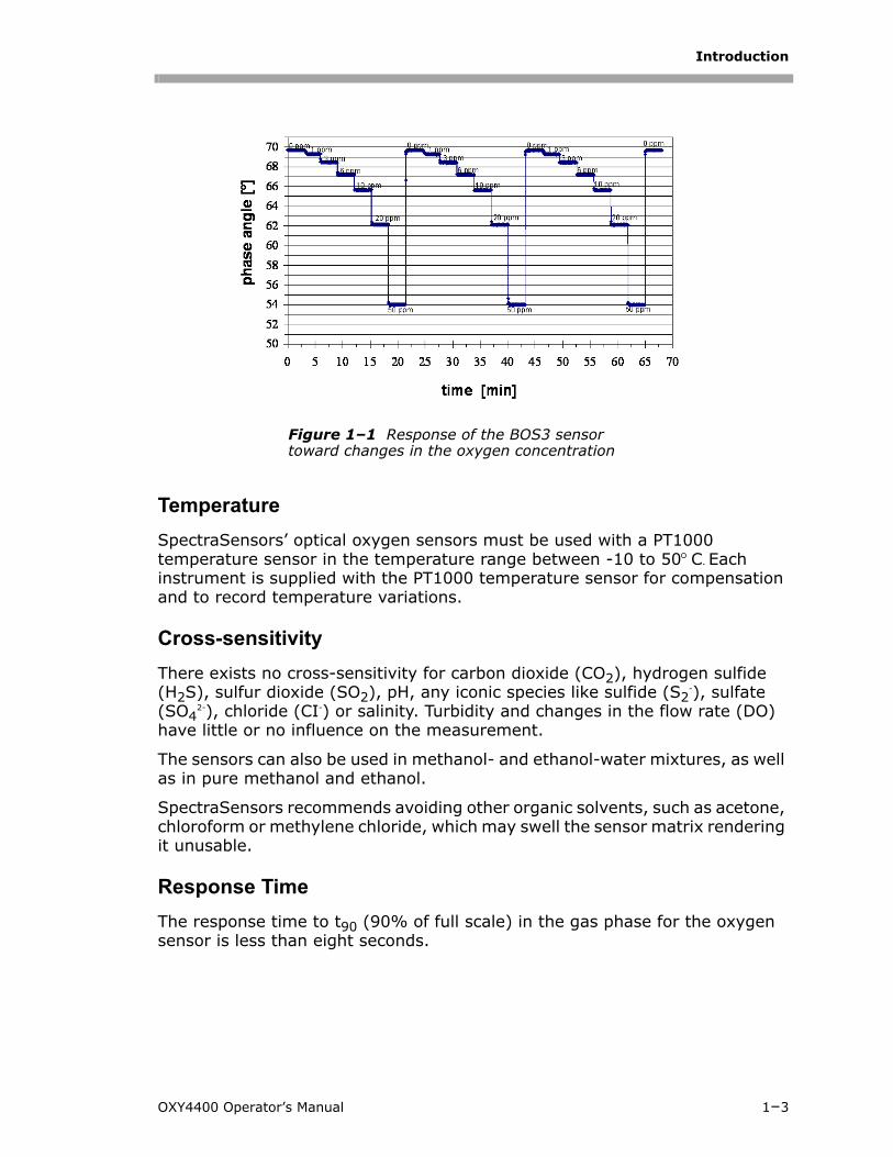
The operation principle of the optical oxygen sensor is based on the fluorescence quenching of luminescence caused by a collision between molecular oxygen and luminescent dye molecules in the excited state. Figure 1–1 shows a typical response curve of the oxygen-sensitive sensor. In the presence of oxygen, the signal (in this case, the phase angle ) decreases.
1–2 4900002060 rev. C 4-9-15
Introduction
Temperature
SpectraSensors’ optical oxygen sensors must be used with a PT1000 temperature sensor in the temperature range between -10 to 50 C. Each instrument is supplied with the PT1000 temperature sensor for compensation and to record temperature variations.
Cross-sensitivity
There exists no cross-sensitivity for carbon dioxide (CO2), hydrogen sulfide (H2S), sulfur dioxide (SO2), pH, any iconic species like sulfide (S2
-), sulfate (SO4
2-), chloride (CI-) or salinity. Turbidity and changes in the flow rate (DO) have little or no influence on the measurement.
The sensors can also be used in methanol- and ethanol-water mixtures, as well as in pure methanol and ethanol.
SpectraSensors recommends avoiding other organic solvents, such as acetone, chloroform or methylene chloride, which may swell the sensor matrix rendering it unusable.
Response Time
The response time to t90 (90% of full scale) in the gas phase for the oxygen sensor is less than eight seconds.
Figure 1–1 Response of the BOS3 sensor toward changes in the oxygen concentration
OXY4400 Operator’s Manual 1–3
Oxygen Analyzer
1–4 4900002060 rev. C 4-9-15
Housing for Oxygen in Natural Gas (DP-BOS3-L5-ST5-NOP)
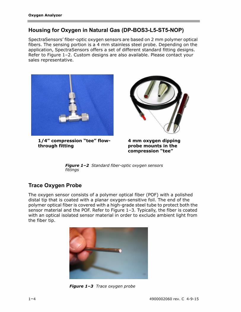
SpectraSensors’ fiber-optic oxygen sensors are based on 2 mm polymer optical fibers. The sensing portion is a 4 mm stainless steel probe. Depending on the application, SpectraSensors offers a set of different standard fitting designs. Refer to Figure 1–2. Custom designs are also available. Please contact your sales representative.
Trace Oxygen Probe
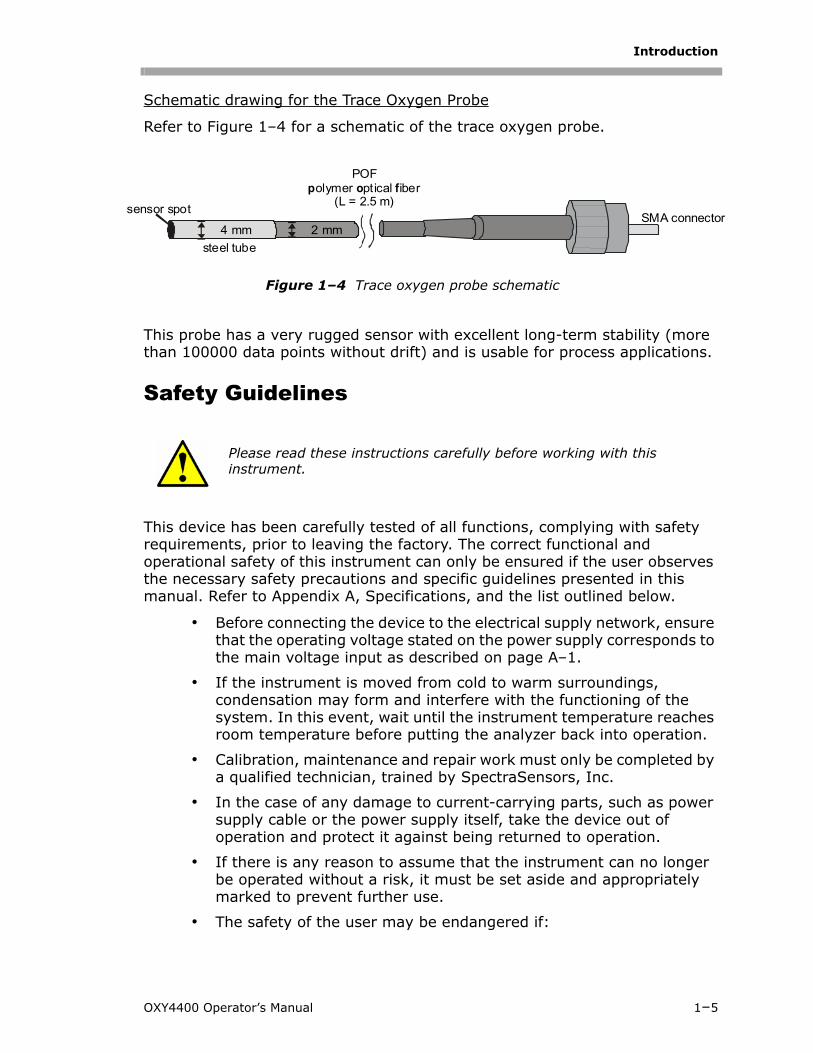
The oxygen sensor consists of a polymer optical fiber (POF) with a polished distal tip that is coated with a planar oxygen-sensitive foil. The end of the polymer optical fiber is covered with a high-grade steel tube to protect both the sensor material and the POF. Refer to Figure 1–3. Typically, the fiber is coated with an optical isolated sensor material in order to exclude ambient light from the fiber tip.
1/4” compression “tee” flow-through fitting
4 mm oxygen dipping probe mounts in the compression “tee”
Figure 1–2 Standard fiber-optic oxygen sensors fittings
Figure 1–3 Trace oxygen probe
Introduction
s
Schematic drawing for the Trace Oxygen Probe
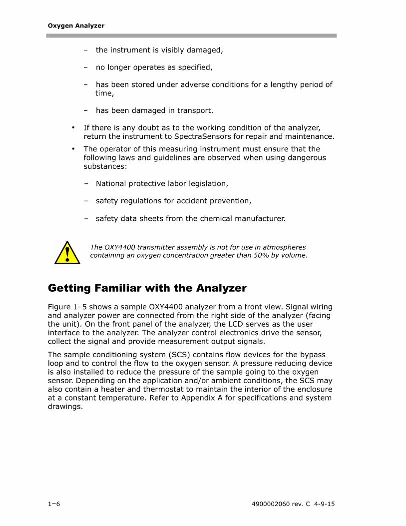
Refer to Figure 1–4 for a schematic of the trace oxygen probe.
This probe has a very rugged sensor with excellent long-term stability (more than 100000 data points without drift) and is usable for process applications.
Safety Guidelines
This device has been carefully tested of all functions, complying with safety requirements, prior to leaving the factory. The correct functional and operational safety of this instrument can only be ensured if the user observes the necessary safety precautions and specific guidelines presented in this manual. Refer to Appendix A, Specifications, and the list outlined below.
• Before connecting the device to the electrical supply network, ensure that the operating voltage stated on the power supply corresponds to the main voltage input as described on page A–1.
• If the instrument is moved from cold to warm surroundings, condensation may form and interfere with the functioning of the system. In this event, wait until the instrument temperature reaches room temperature before putting the analyzer back into operation.
• Calibration, maintenance and repair work must only be completed by a qualified technician, trained by SpectraSensors, Inc.
• In the case of any damage to current-carrying parts, such as power supply cable or the power supply itself, take the device out of operation and protect it against being returned to operation.
• If there is any reason to assume that the instrument can no longer be operated without a risk, it must be set aside and appropriately marked to prevent further use.
• The safety of the user may be endangered if:
Please read these instructions carefully before working with this instrument.
ensor spotSMA connector
2 mm4 mm
POFolymer ptical iber
(L = 2.5 m)p o f
steel tube
Figure 1–4 Trace oxygen probe schematic
OXY4400 Operator’s Manual 1–5
Oxygen Analyzer
– the instrument is visibly damaged,
– no longer operates as specified,
– has been stored under adverse conditions for a lengthy period of time,
– has been damaged in transport.
• If there is any doubt as to the working condition of the analyzer, return the instrument to SpectraSensors for repair and maintenance.
• The operator of this measuring instrument must ensure that the following laws and guidelines are observed when using dangerous substances:
– National protective labor legislation,
– safety regulations for accident prevention,
– safety data sheets from the chemical manufacturer.
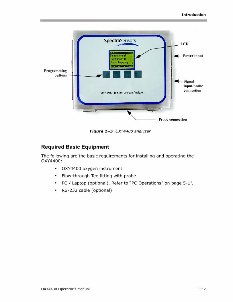
Getting Familiar with the AnalyzerFigure 1–5 shows a sample OXY4400 analyzer from a front view. Signal wiring and analyzer power are connected from the right side of the analyzer (facing the unit). On the front panel of the analyzer, the LCD serves as the user interface to the analyzer. The analyzer control electronics drive the sensor, collect the signal and provide measurement output signals.
The sample conditioning system (SCS) contains flow devices for the bypass loop and to control the flow to the oxygen sensor. A pressure reducing device is also installed to reduce the pressure of the sample going to the oxygen sensor. Depending on the application and/or ambient conditions, the SCS may also contain a heater and thermostat to maintain the interior of the enclosure at a constant temperature. Refer to Appendix A for specifications and system drawings.
The OXY4400 transmitter assembly is not for use in atmospheres containing an oxygen concentration greater than 50% by volume.
1–6 4900002060 rev. C 4-9-15
Introduction
Required Basic Equipment
The following are the basic requirements for installing and operating the OXY4400:
• OXY4400 oxygen instrument
• Flow-through Tee fitting with probe
• PC / Laptop (optional). Refer to “PC Operations” on page 5-1”.
• RS-232 cable (optional)
Figure 1–5 OXY4400 analyzer
Programmingbuttons
LCD
Power input
Signal input/probe connection
Probe connection
OXY4400 Operator’s Manual 1–7

Oxygen Analyzer
THIS PAGE INTENTIONALLY LEFT BLANK
1–8 4900002060 rev. C 4-9-15
2 - INSTALLATION
This section describes the processes used to install and setup your OXY4400. Once the analyzer arrives, you should take a few minutes to examine the contents before installing the unit.
What Should be Included in the Shipping BoxThe contents of the crates should include:
• The SpectraSensors OXY4400 analyzer
• A document CD, which includes this manual and other system documents
• One external serial cable
• Additional accessories or options as ordered
If any of these contents are missing, contact your sales representative.
Inspecting the Analyzer Unpack and place the unit on a flat surface. Carefully inspect all enclosures for dents, dings, or general damage. Inspect the supply and return connections for damage, such as bent tubing. Report any damage to the carrier.
Each analyzer is custom configured with various accessories and options. If there is any discrepancy, please contact your sales representative.
Installing the Analyzer Installing the analyzer is relatively easy requiring only a few steps that, when carefully followed, will ensure proper mounting and connection. This section includes information regarding:
• Hardware and Tools for Installation
• Mounting the Analyzer
• Connecting Electrical Power to the Analyzer
• Connecting Electrical Power to the Enclosure Heater
• Connecting the Analog Outputs/Analog Inputs
• Connecting the Gas Lines
Avoid jolting the instrument by dropping it or banging it against a hard surface which may disturb the optical alignment.
OXY4400 Operator’s Manual 2–1
Oxygen Analyzer
Hardware and Tools for InstallationDepending on the particular configuration of accessories and options ordered, you may need the following hardware and tools to complete the installation process.
Hardware:
• 3/8” Unistrut® (or equivalent) bolts and spring nuts
• Stainless steel tubing (SpectraSensors recommends using 1/4” O.D. x 0.035” wall thickness, seamless stainless steel tubing)
• 3/4” conduit
• Source of plant nitrogen gas (4 SCFH) for purge unit(s), if applicable
• 3/8” x 1-1/2” machine screws and nuts
Tools:
• Hand drill and bits
• Tape measure
• Level
• Pencil
• 9/16” socket wrench
• Screw driver
• 9/16” open-end wrench
• Needle-nose pliers
• Crescent wrench
Mounting the AnalyzerThe OXY4400 analyzer is manufactured for wall or Unistrut® (or equivalent) metal framing installations. Depending on your application and configuration, the analyzer will come mounted on a plate or Unistrut frame. Refer to Appendix A for drawings with detailed mounting dimensions.
When mounting the analyzer, be sure not to position the instrument so that it is difficult to operate adjacent devices. Allow 3 feet (1 m) of room in front of the analyzer and any switches.
It is critical to mount the analyzer so that the supply and return lines reach the supply and return connections on the chassis while still maintaining flexibility so that the sample lines are not under excessive stress.
2–2 4900002060 rev. C 4-9-15
Installation
To mount the analyzer:
1. Select a suitable location to mount the analyzer. Choose a shaded area or use an optional analyzer hood (or equivalent) to minimize sun exposure.
2. Locate the mounting holes on your unit.
3. For wall installations, mark the centers of the top mounting holes. Mounting dimensions are shown in Appendix A.
4. Drill the appropriate size holes for the screws you are using.
5. Hold the analyzer in place and fasten with the top screws.
6. Repeat for the bottom mounting holes.
Once all four screws are tightened the analyzer should be very secure and ready for the electrical connections.
Connecting Electrical Power to the AnalyzerDepending on your configuration, your analyzer will be configured for 120VAC/240VAC @ 50/60 Hz single-phase input, or optionally 24VDC input. Check the manufacturing data label or the terminal block labels to determine the power input requirements. All work must be performed by personnel qualified in electrical conduit installation. Conduit seals should be used where appropriate in compliance with local regulations.
Depending on your configuration, the electrical wiring can be connected to the analyzer through an opening located at the right of the electronics enclosure (facing the front). Refer to Figure 1–5 on page 1–7.
SpectraSensors analyzers are designed for operation within the specified ambient temperature range. Intense sun exposure in some areas may cause the analyzer temperature to exceed the maximum.
Hazardous voltage and risk of electric shock. Before attaching the wiring to the analyzer, make sure all power to the wires is off.
Careful consideration should be taken when grounding. Properly ground the unit by connecting ground leads to the grounding studs provided throughout the system that are labeled with the ground symbol .
Do not exceed the 24VDC power rating or electronics will be damaged.
OXY4400 Operator’s Manual 2–3
Oxygen Analyzer
Units with an enclosure heater in the sample conditioning system (SCS) will have an additional power connection through a conduit hub located at the bottom right of the heater enclosure (refer to Appendix A).
To connect electrical power to the analyzer:
1. Open the OXY4400 analyzer electronics enclosure door. Take care not to disturb the electrical assembly inside.
2. Run conduit from the power distribution panel to the conduit hub on the analyzer electronics enclosure labeled for power input.
3. For AC systems, pull ground, neutral and hot wires into the electronics enclosure.
For DC systems, pull ground, plus and minus wires.
4. Strip back the jacket and/or insulation of the wires just enough to connect to the power terminal block.
5. For single phase power connections, attach the neutral and hot wires to the power terminal block by connecting the neutral wire to the terminal marked “N” and the hot wire to the terminal marked “L.” Refer to Table 2–1.
6. For AC split phase systems, attach the two hot legs to the terminal block by connecting one of the hot wires to the terminal marked “L1" and the other hot wire to the terminal marked “L2.”
For DC systems, connect the minus wire to the terminal marked “-,” and the positive wire to the terminal marked “+.” Refer to Table 2–1.
7. Connect the ground wire to the ground terminal marked .
Hazardous voltage and risk of electric shock. Failure to properly ground the analyzer may create a high-voltage shock hazard.
Conduit seals should be used where appropriate in compliance with local regulations.
Because the breaker in the power distribution panel or switch will be the primary means of disconnecting the power from the analyzer, the power distribution panel should be located in close proximity to the equipment and within easy reach of the operator, or within 10 feet of the analyzer.
An approved switch or circuit breaker rated for 15 amps should be used and clearly marked as the disconnecting device for the analyzer.
2–4 4900002060 rev. C 4-9-15
Installation
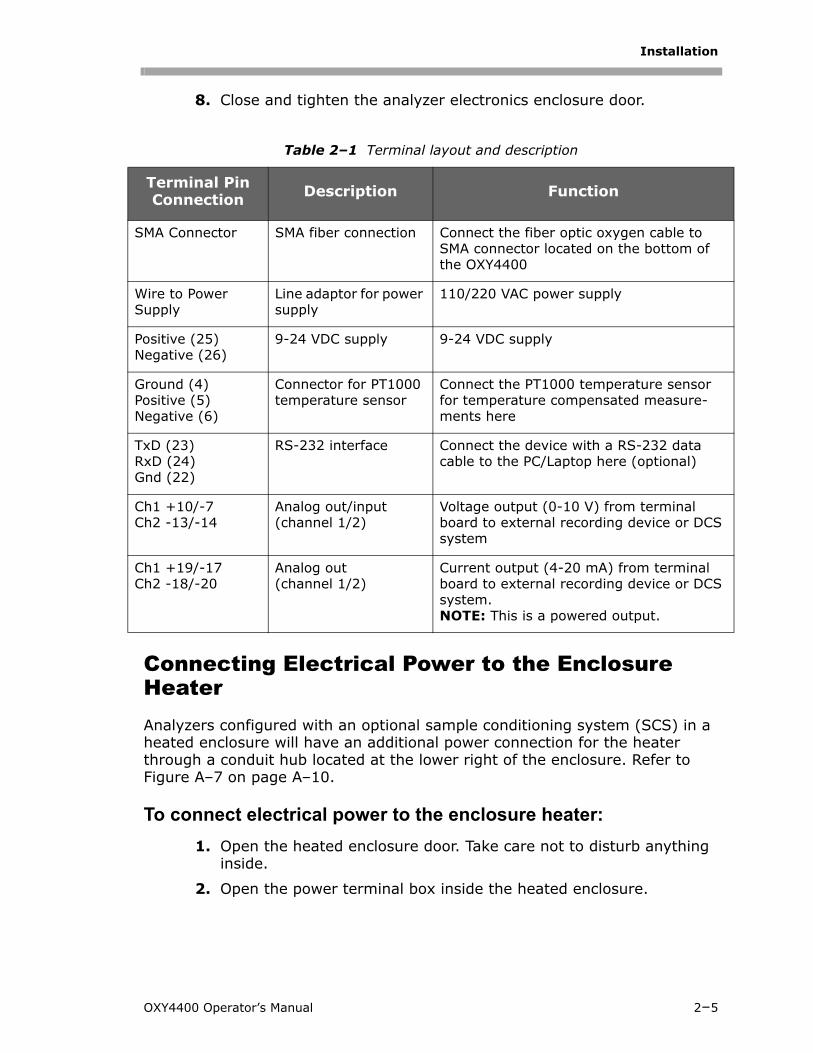
8. Close and tighten the analyzer electronics enclosure door.
Connecting Electrical Power to the Enclosure HeaterAnalyzers configured with an optional sample conditioning system (SCS) in a heated enclosure will have an additional power connection for the heater through a conduit hub located at the lower right of the enclosure. Refer to Figure A–7 on page A–10.
To connect electrical power to the enclosure heater:
1. Open the heated enclosure door. Take care not to disturb anything inside.
2. Open the power terminal box inside the heated enclosure.
Table 2–1 Terminal layout and description
Terminal Pin Connection Description Function
SMA Connector SMA fiber connection Connect the fiber optic oxygen cable to SMA connector located on the bottom of the OXY4400
Wire to Power Supply
Line adaptor for power supply
110/220 VAC power supply
Positive (25) Negative (26)
9-24 VDC supply 9-24 VDC supply
Ground (4)Positive (5)Negative (6)
Connector for PT1000 temperature sensor
Connect the PT1000 temperature sensor for temperature compensated measure-ments here
TxD (23)RxD (24)Gnd (22)
RS-232 interface Connect the device with a RS-232 data cable to the PC/Laptop here (optional)
Ch1 +10/-7Ch2 -13/-14
Analog out/input(channel 1/2)
Voltage output (0-10 V) from terminal board to external recording device or DCS system
Ch1 +19/-17Ch2 -18/-20
Analog out(channel 1/2)
Current output (4-20 mA) from terminal board to external recording device or DCS system. NOTE: This is a powered output.
OXY4400 Operator’s Manual 2–5
Oxygen Analyzer
3. Run conduit from the power distribution panel to the conduit hub on the lower right side of the heated enclosure labeled for power input.
4. Pull ground, neutral and hot wires (#14 AWG minimum) into the power terminal box inside the heated enclosure.
5. Strip back the jacket and/or insulation of the wires just enough to connect to the power terminal block.
6. For AC systems, attach the neutral and hot wires to the power terminal by connecting the neutral wire to the terminal marked “N,” the hot wire to the terminal marked “L.”
7. Connect the ground wire to the ground terminal marked .
8. Close and latch the heated enclosure door.
Connecting the Analog Outputs/Analog Inputs The OXY4400 is equipped with four independent analog outputs and two analog inputs. The 4-20 mA current loop and serial output are connected to a mating terminal block located inside the analyzer electronics enclosure. By default, the 4-20 mA current loop analog inputs (I1/I2) are set to inactive.
The analog outputs are programmable to oxygen temperature, phase shift or signal amplitude. To allow external data collection, two input ports are available (i.e., external pressure sensor).
Connections can be made with customer-supplied cables for the current loop and alarms and factory-supplied cable for the serial connection. Consult the wiring diagram in Figure A–1 on page A–4.
Conduit seals should be used where appropriate in compliance with local regulations.
Because the breaker in the power distribution panel or switch will be the primary means of disconnecting the power from the analyzer, the power distribution panel or switch should be located in close proximity to the equipment and within easy reach of the operator.
An approved switch or circuit breaker rated for 15 amps should be used and clearly marked as the disconnecting device for the analyzer.
Certified glands and cables should be used where appropriate in compliance with local regulations.
2–6 4900002060 rev. C 4-9-15
Installation
To connect the analog outputs/analog inputs:
1. Disconnect power from the analyzer and open the electronics enclosure cover. Take care not to disturb the electrical assembly inside.
2. Run conduit from the analog outputs/inputs receiving station to the conduit hub in the right outside corner of the electronics enclosure.
3. Pull the customer-supplied cables for the source outputs and the SpectraSensors external serial cable (included in the shipping box) through the conduit into the electronics enclosure.
4. Strip back the jacket and insulation of the current loop output and serial cables just enough to connect to the mating terminal block.
5. Connect the 4-20 mA current loop I1/I2 output wires to the appropriate terminals, as indicated in Table 2–1 on page 2–5.
6. Connect the serial cable wires to the appropriate terminals according to Table 2–1. For reference, Table 2–1 also shows the corresponding pin numbers for configuring a nine-pin Sub-D connector for connection to a computer serial port.
7. To complete the connection, connect the other end of the current loop wires to a current loop receiver and the external serial cable to a serial port on your computer.
Connecting the Gas Lines Once you have verified that the analyzer is wired correctly, you are ready to connect the sample supply, sample bypass and sample return lines. Consult the layout and flow diagrams in Appendix A for guidance on connections for a SpectraSensors provided sample conditioning system (SCS). All work must be performed by qualified technicians.
SpectraSensors recommends using 1/4” O.D x 0.035” wall thickness, seamless stainless steel tubing.
Hazardous voltage and risk of electric shock. Turn off and lock out system power before opening the electronics enclosure and making any connections.
Process samples may contain hazardous material in potentially flammable and/or toxic concentrations. Personnel should have a thorough knowledge and understanding of the physical properties and safety precautions for the sample contents before installing the sample conditioning system (SCS).
OXY4400 Operator’s Manual 2–7
Oxygen Analyzer
To connect the sample supply line:
1. Install sample supply line to the inlet on the SCS panel. Refer to Appendix A.
2. Adjust the pressure regulator to 8 PSIG. Refer to drawings in Appendix A for recommended settings.
3. Adjust flowmeter to 1 SLPM. Refer to drawings in Appendix A for recommended settings.
4. Tighten all input/output fittings 1-1/4 turns with a wrench from finger tight.
5. Check all customer connections for gas leaks. SpectraSensors recommends using a liquid leak test.
To connect the sample bypass/sample return:
1. Confirm that the atmospheric vent header shut-off valve is closed.
2. Determine appropriate tubing route from the SCS to the atmospheric vent header.
3. Run stainless steel tubing from the bypass/sample return port to the atmospheric vent header connection. Bend tubing using industrial grade benders, check tubing fit to ensure proper seating between the tubing and fittings. Fully ream all tubing ends. Blow out the lines for 10–15 seconds with clean, dry nitrogen or air prior to making the connection.
4. Connect the sample return tube to the SCS using the 1/4” stainless steel compression-type fitting provided.
5. Tighten all new fittings 1-1/4 turns with a wrench from finger tight. Secure tubing to appropriate structural supports as required.
All valves, regulators, switches, etc. should be operated in accordance with site lock-out/tag-out procedures.
Do not exceed 20 PSIG to sample conditioning system. Damage to the oxygen sensor may result.
All valves, regulators, switches, etc. should be operated in accordance with site lock-out/tag-out procedures.
2–8 4900002060 rev. C 4-9-15
Installation
6. Check all connections for gas leaks. SpectraSensors recommends using a liquid leak detector.
Installing the Temperature (RTD) ProbeMost configurations include an installed RTD (Resistance Temperature Device) probe. If the OXY4400 is provided without an accompanying sample conditioning system (SCS), use the following procedure to connect the RTD probe to the SCS.
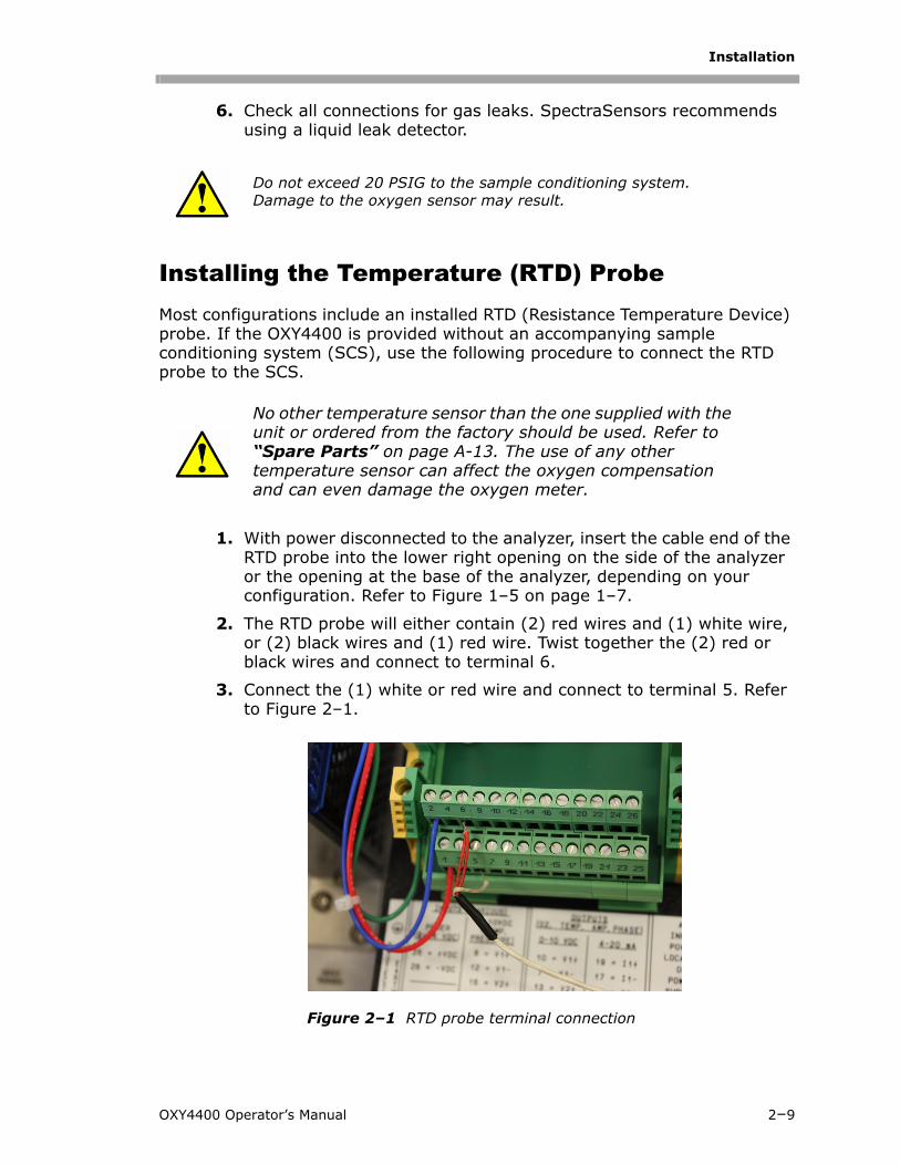
1. With power disconnected to the analyzer, insert the cable end of the RTD probe into the lower right opening on the side of the analyzer or the opening at the base of the analyzer, depending on your configuration. Refer to Figure 1–5 on page 1–7.
2. The RTD probe will either contain (2) red wires and (1) white wire, or (2) black wires and (1) red wire. Twist together the (2) red or black wires and connect to terminal 6.
3. Connect the (1) white or red wire and connect to terminal 5. Refer to Figure 2–1.
Do not exceed 20 PSIG to the sample conditioning system. Damage to the oxygen sensor may result.
No other temperature sensor than the one supplied with the unit or ordered from the factory should be used. Refer to “Spare Parts” on page A-13. The use of any other temperature sensor can affect the oxygen compensation and can even damage the oxygen meter.
Figure 2–1 RTD probe terminal connection
OXY4400 Operator’s Manual 2–9
Oxygen Analyzer
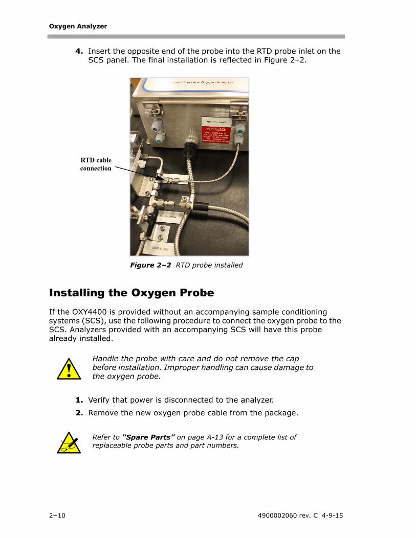
4. Insert the opposite end of the probe into the RTD probe inlet on the SCS panel. The final installation is reflected in Figure 2–2.
Installing the Oxygen ProbeIf the OXY4400 is provided without an accompanying sample conditioning systems (SCS), use the following procedure to connect the oxygen probe to the SCS. Analyzers provided with an accompanying SCS will have this probe already installed.
1. Verify that power is disconnected to the analyzer.
2. Remove the new oxygen probe cable from the package.
Handle the probe with care and do not remove the cap before installation. Improper handling can cause damage to the oxygen probe.
Refer to “Spare Parts” on page A-13 for a complete list of replaceable probe parts and part numbers.
RTD cableconnection
Figure 2–2 RTD probe installed
2–10 4900002060 rev. C 4-9-15
Installation
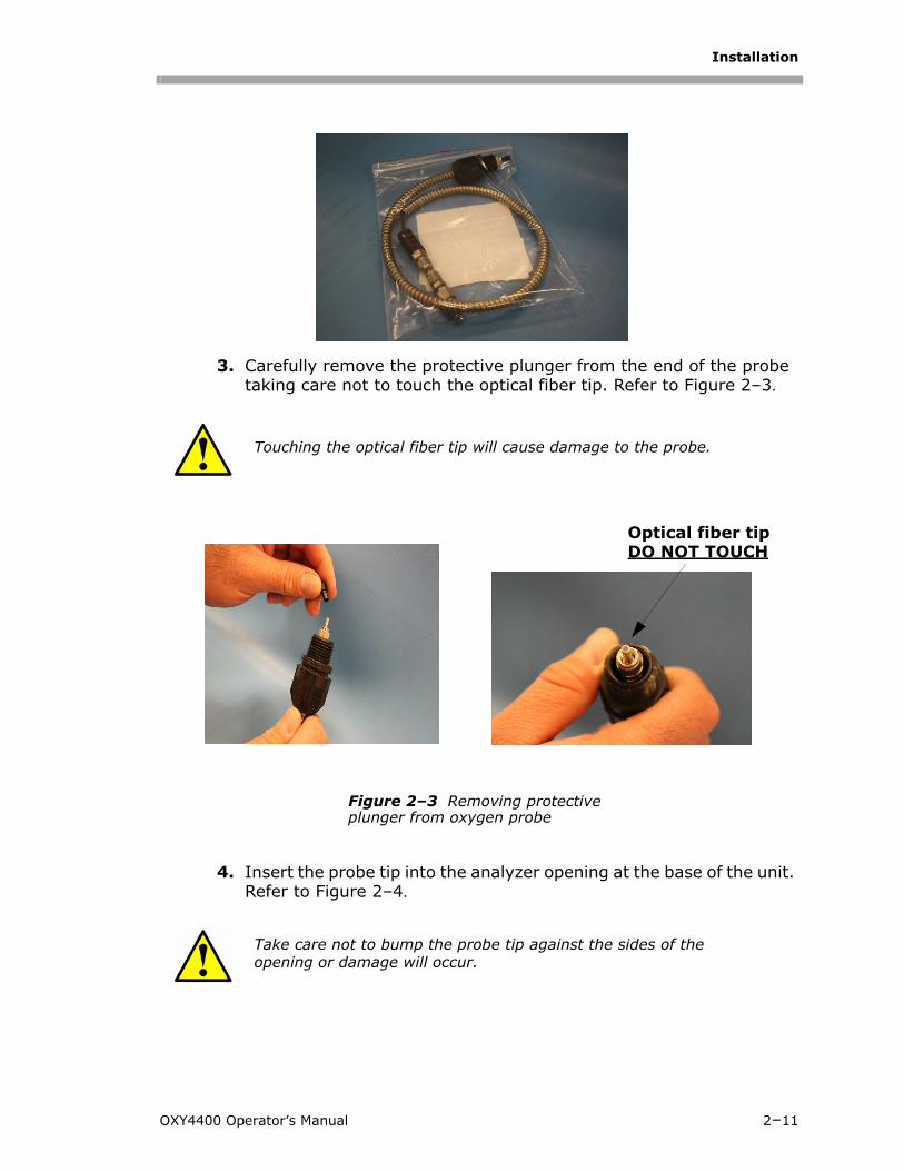
3. Carefully remove the protective plunger from the end of the probe taking care not to touch the optical fiber tip. Refer to Figure 2–3.
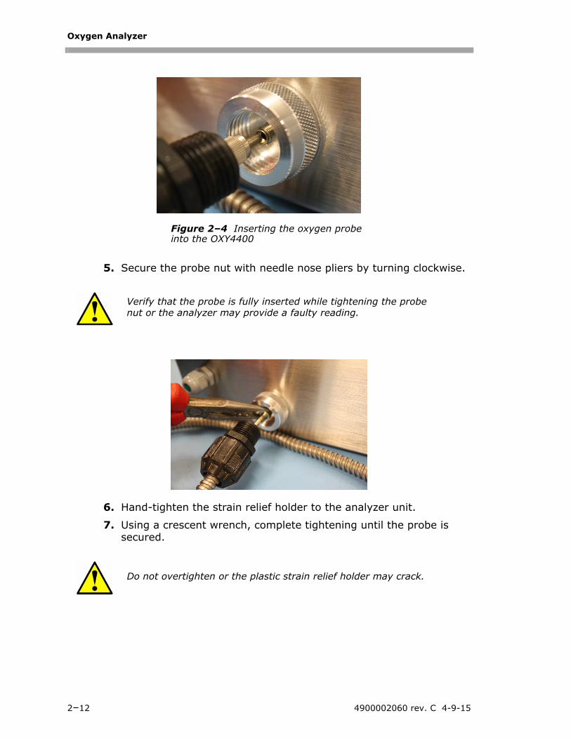
4. Insert the probe tip into the analyzer opening at the base of the unit. Refer to Figure 2–4.
Touching the optical fiber tip will cause damage to the probe.
Take care not to bump the probe tip against the sides of the opening or damage will occur.
Optical fiber tipDO NOT TOUCH
Figure 2–3 Removing protective plunger from oxygen probe
OXY4400 Operator’s Manual 2–11
Oxygen Analyzer
5. Secure the probe nut with needle nose pliers by turning clockwise.
6. Hand-tighten the strain relief holder to the analyzer unit.
7. Using a crescent wrench, complete tightening until the probe is secured.
Verify that the probe is fully inserted while tightening the probe nut or the analyzer may provide a faulty reading.
Do not overtighten or the plastic strain relief holder may crack.
Figure 2–4 Inserting the oxygen probe into the OXY4400
2–12 4900002060 rev. C 4-9-15
Installation
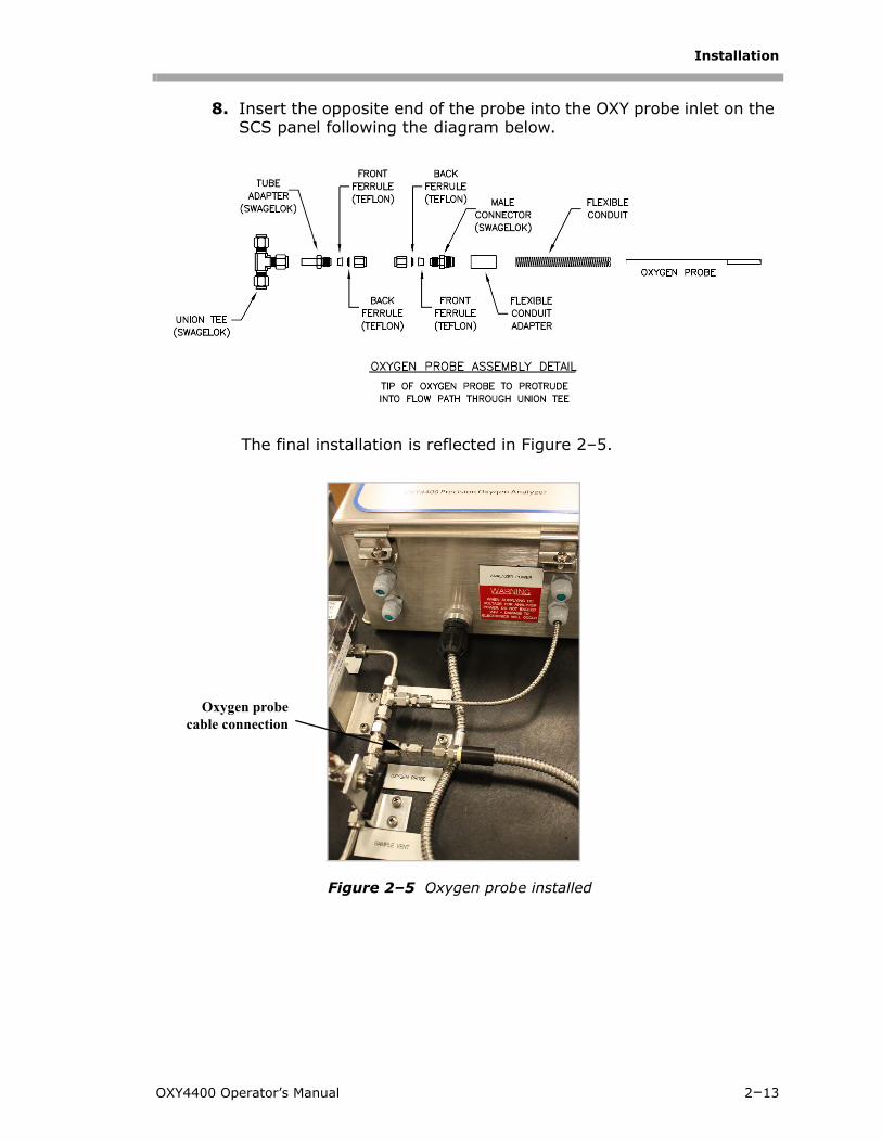
8. Insert the opposite end of the probe into the OXY probe inlet on the SCS panel following the diagram below.
The final installation is reflected in Figure 2–5.
Oxygen probecable connection
Figure 2–5 Oxygen probe installed
OXY4400 Operator’s Manual 2–13
Oxygen Analyzer
Connecting the Calibration Gas (Optional)For systems with a manual calibration port, an appropriate calibration gas source will need to be connected to the SCS. For more information, refer to the drawings in Appendix A.
Conditioning the SCS TubingNewly installed systems invariably have some trace contaminants and/or are intended for measuring trace amounts of gas constituents that tend to cling to system walls resulting in erroneous readings if the constituents are not in equilibrium with the system walls. Therefore, once the analyzer and SCS are completely connected, the entire system (i.e., from the sample source valve to the vent or return) should be conditioned by flowing sample gas through the system for up to 12 hours (or until reading stabilizes) after the system is powered up and before actual readings are taken. Progress of the system conditioning can be monitored via the gas concentration readings. Once the gas constituents have reached equilibrium with the system walls, the readings should stabilize.
2–14 4900002060 rev. C 4-9-15
3 - SAMPLE CONDITIONING SYSTEM (SCS) OPERATION
Each SCS has been specifically designed to deliver a sample stream to the analyzer that is representative of the process stream at the time of sampling. Refer to Appendix A for configuration drawings. To ensure the integrity of the sample stream and its analysis, care must be taken to install and operate the SCS properly. Therefore, any personnel intending to operate or service the SCS should have a thorough understanding of the process application and the design of the SCS.
Most problems experienced with sample systems tend to result from operating the system differently than intended. In some cases, the actual process conditions may be different than originally specified (e.g., flow rates, presence of contaminants, particulates, or condensables that may only exist under upset conditions). By establishing understanding of the application and the design of the system, most issues can be avoided altogether or easily diagnosed and corrected ensuring successful normal operation.
If there are any remaining questions concerning the design, operation, or maintenance of the SCS, contact “Customer Service” on page B-7.
About the SCSFor a typical full-featured SCS, refer to Figure A–1, sample gas enters the sample conditioning unit [at the specified supply pressure set by a customer-supplied upstream regulator] via the sample supply port, passes through a shut-off valve, pressure regulator that maintains constant pressure in the measurement cell, and membrane separator where any liquid in the stream is removed. Liquid removed by the membrane separator passes through the bypass loop and collects in a filter housing. A continuous flow (set to the specified level by a metering valve and flowmeter) not only flushes the liquid from the membrane separator but also maintains flow through the sample lines, which reduces sample variation.
The flow exiting the bypass loop should be vented to a safe location.
Personnel should have a thorough understanding of the procedures presented here before operating the sample conditioning system.
The process sample at the sample tap may be at a high pressure. Make sure that the field pressure reducing regulator is equipped with an appropriate pressure relief valve. Use extreme caution when operating the sample probe isolation valve and field pressure reducing regulator.
OXY4400 Operator’s Manual 3–1
Oxygen Analyzer
Checking the SCS InstallationBefore operating the system for the first time, a careful check of the installation of the entire SCS from the sample probe to the vent is recommended.
To perform SCS installation checks:
1. Confirm that the sample probe is correctly installed at the process supply tap and that the sample probe isolation valve is closed.
2. Confirm that the field pressure reducing station is installed properly at the sample probe.
3. Confirm that the relief valve at the field pressure reducing station has been set to the specified setpoint.
4. Confirm that all valves are closed.
5. Confirm that the atmospheric vent is properly connected.
6. Confirm that the analyzer house atmospheric vent is properly installed, if applicable.
7. Confirm that all sample system tubing has been thoroughly leak checked.
Starting up the SCSAfter the SCS installation has been thoroughly checked, you are ready to begin preparing for initial SCS startup.
To prepare for SCS startup:
8. If applicable, confirm proper heating of the sample supply tubing.
9. Confirm that all sample system shut-off valves are closed.
10. Confirm that the sample bypass and analyzer flowmeter control valves are gently closed (adjustment knob turned clockwise).
To start up the sample bypass stream on process sample:
1. Open the atmospheric vent header shut-off valve for the sample bypass effluent from the SCS, if applicable.
2. Open the sample supply port shut-off valve and slowly open the pressure regulator (turning knob clockwise).
Do not overtighten the control valves or damage could occur.
3–2 4900002060 rev. C 4-9-15
Sample Conditioning System (SCS) Operation
3. Set the inlet pressure regulator on the panel to a setting that will maintain the specified flowmeter settings and provide good control using the analyzer and bypass flow control valves.
4. Open the bypass flowmeter control valve to establish sample flow from the sample probe and set the flowmeter to the specified value.
To start up the analyzer on process sample:
1. Open the sample flowmeter control valve to approximately the specified flow.
2. Adjust the sample flowmeter control valve to the specified flow.
3. Confirm the sample flow and pressure setpoints and readjust the control valves and pressure regulator to the specified setpoints, if necessary.
4. Confirm the sample bypass flow and readjust the bypass control valve to the specified setpoint, if necessary. The SCS is now operating with the process sample.
5. Power up the analyzer according to the procedure given in the analyzer operator’s manual.
Shutting Down the SCS
Do not exceed 10 PSIG at any time in the cell.
The adjustment setpoints of the analyzer flowmeter and pressure regulator will be interactive and may require multiple adjustments until the final setpoints are obtained.
The analyzer system has been designed for the sample flow rate specified. A lower than specified sample flow rate may adversely affect analyzer performance. If you are unable to attain the specified sample flow rate, contact your factory sales representative.
The process sample at the sample tap is at a high pressure. A pressure reducing regulator is located at the sample tap to reduce the sample pressure and enable operation of the SCS at a low pressure. Use extreme caution when operating the sample probe isolation valve.
OXY4400 Operator’s Manual 3–3
Oxygen Analyzer
1. Close the sample supply shut-off valve.
2. Allow the sample to flow until all residual gas has dissipated from the lines as indicated by no flow on the sample and sample bypass flowmeters.
3. Close the atmospheric vent header shut-off valve for the combined sample bypass and measurement cell effluent from the SCS.
3–4 4900002060 rev. C 4-9-15
4 - CONFIGURATION
The instructions provided in this chapter should be used to start-up and configure the OXY4400. On the face of the analyzer is an LCD with programming and data readouts. Refer to Figure 1–5.
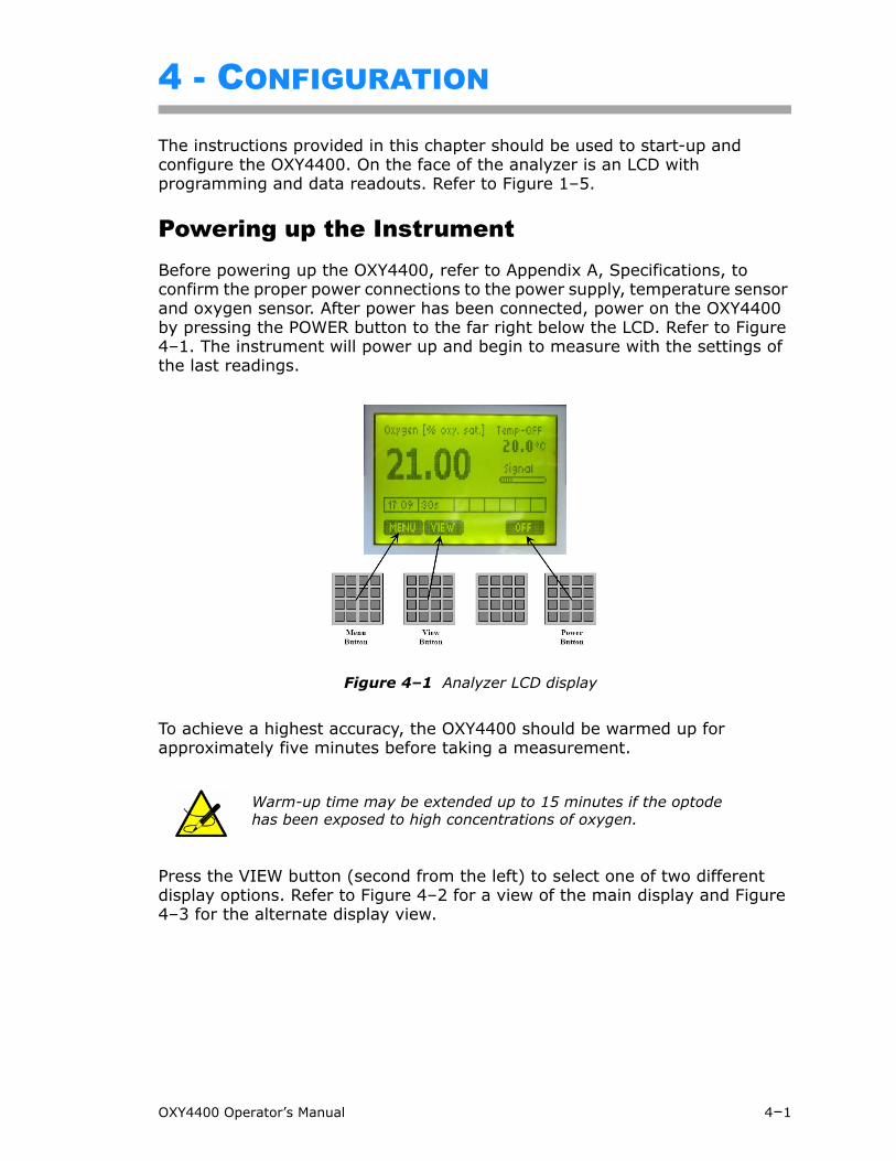
Powering up the InstrumentBefore powering up the OXY4400, refer to Appendix A, Specifications, to confirm the proper power connections to the power supply, temperature sensor and oxygen sensor. After power has been connected, power on the OXY4400 by pressing the POWER button to the far right below the LCD. Refer to Figure 4–1. The instrument will power up and begin to measure with the settings of the last readings.
To achieve a highest accuracy, the OXY4400 should be warmed up for approximately five minutes before taking a measurement.
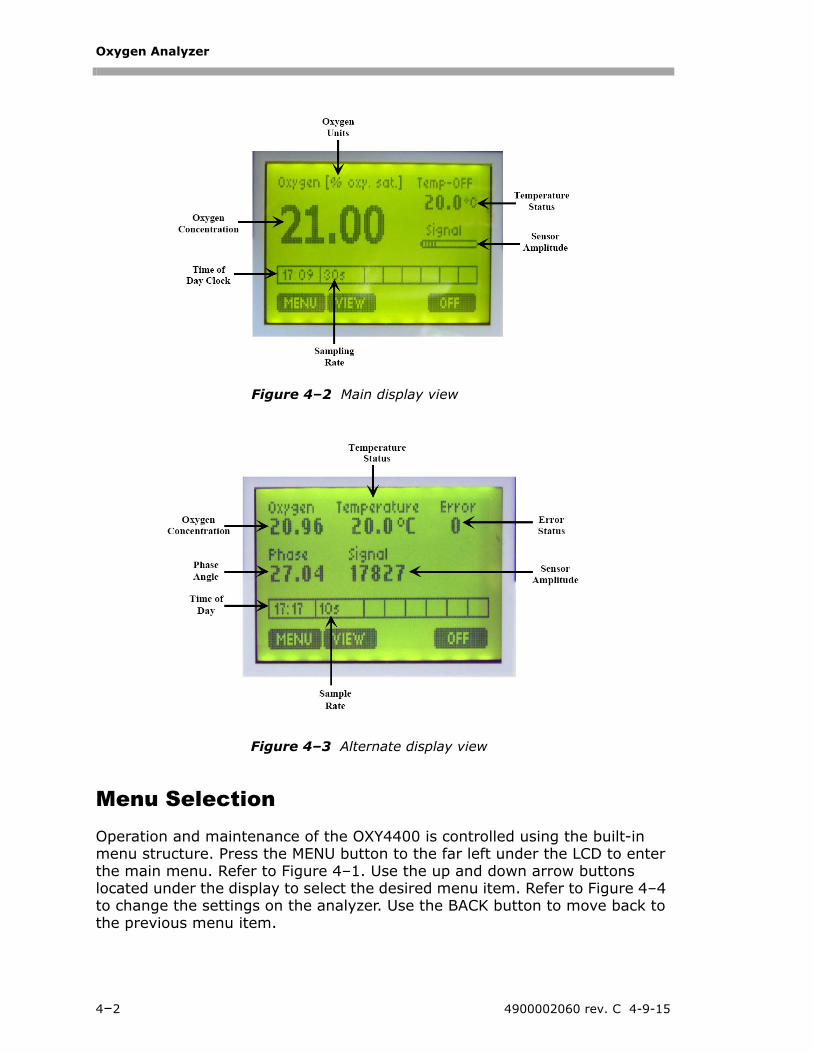
Press the VIEW button (second from the left) to select one of two different display options. Refer to Figure 4–2 for a view of the main display and Figure 4–3 for the alternate display view.
Warm-up time may be extended up to 15 minutes if the optode has been exposed to high concentrations of oxygen.
Figure 4–1 Analyzer LCD display
OXY4400 Operator’s Manual 4–1
Oxygen Analyzer
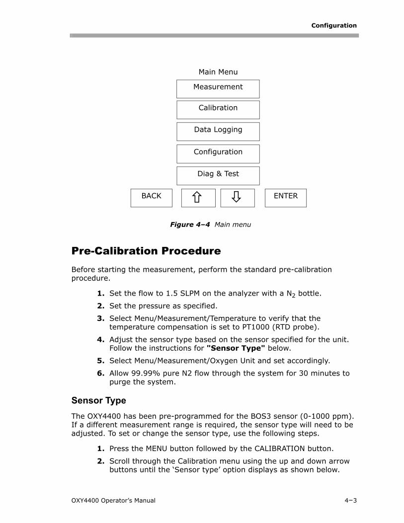
Menu SelectionOperation and maintenance of the OXY4400 is controlled using the built-in menu structure. Press the MENU button to the far left under the LCD to enter the main menu. Refer to Figure 4–1. Use the up and down arrow buttons located under the display to select the desired menu item. Refer to Figure 4–4 to change the settings on the analyzer. Use the BACK button to move back to the previous menu item.
Figure 4–2 Main display view
Figure 4–3 Alternate display view
4–2 4900002060 rev. C 4-9-15
Configuration
Pre-Calibration ProcedureBefore starting the measurement, perform the standard pre-calibration procedure.
1. Set the flow to 1.5 SLPM on the analyzer with a N2 bottle.
2. Set the pressure as specified.
3. Select Menu/Measurement/Temperature to verify that the temperature compensation is set to PT1000 (RTD probe).
4. Adjust the sensor type based on the sensor specified for the unit. Follow the instructions for "Sensor Type" below.
5. Select Menu/Measurement/Oxygen Unit and set accordingly.
6. Allow 99.99% pure N2 flow through the system for 30 minutes to purge the system.
Sensor Type
The OXY4400 has been pre-programmed for the BOS3 sensor (0-1000 ppm). If a different measurement range is required, the sensor type will need to be adjusted. To set or change the sensor type, use the following steps.
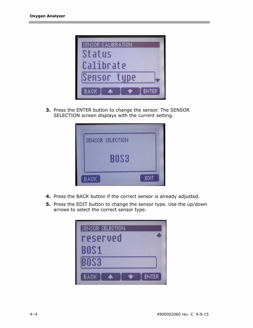
1. Press the MENU button followed by the CALIBRATION button.
2. Scroll through the Calibration menu using the up and down arrow buttons until the ‘Sensor type’ option displays as shown below.
Figure 4–4 Main menu
Main Menu
Calibration
Data Logging
Configuration
Diag & Test
BACK ENTER
Measurement
OXY4400 Operator’s Manual 4–3
Oxygen Analyzer
3. Press the ENTER button to change the sensor. The SENSOR SELECTION screen displays with the current setting.
4. Press the BACK button if the correct sensor is already adjusted.
5. Press the EDIT button to change the sensor type. Use the up/down arrows to select the correct sensor type.
4–4 4900002060 rev. C 4-9-15
Configuration
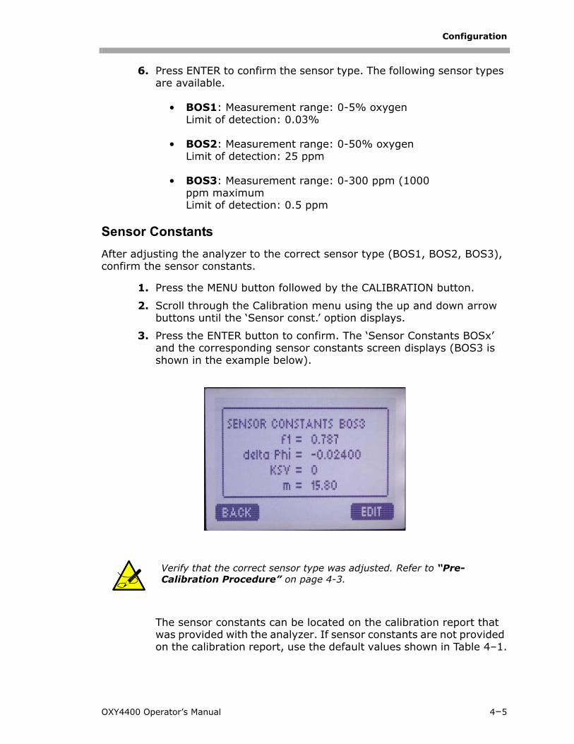
6. Press ENTER to confirm the sensor type. The following sensor types are available.
• BOS1: Measurement range: 0-5% oxygenLimit of detection: 0.03%
• BOS2: Measurement range: 0-50% oxygenLimit of detection: 25 ppm
• BOS3: Measurement range: 0-300 ppm (1000 ppm maximumLimit of detection: 0.5 ppm
Sensor Constants
After adjusting the analyzer to the correct sensor type (BOS1, BOS2, BOS3), confirm the sensor constants.
1. Press the MENU button followed by the CALIBRATION button.
2. Scroll through the Calibration menu using the up and down arrow buttons until the ‘Sensor const.’ option displays.
3. Press the ENTER button to confirm. The ‘Sensor Constants BOSx’ and the corresponding sensor constants screen displays (BOS3 is shown in the example below).
The sensor constants can be located on the calibration report that was provided with the analyzer. If sensor constants are not provided on the calibration report, use the default values shown in Table 4–1.
Verify that the correct sensor type was adjusted. Refer to “Pre-Calibration Procedure” on page 4-3.
OXY4400 Operator’s Manual 4–5
Oxygen Analyzer
4–6 4900002060 rev. C 4-9-15
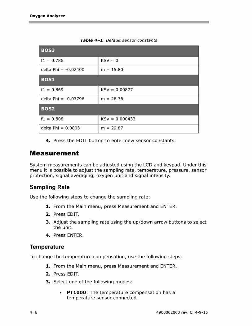
4. Press the EDIT button to enter new sensor constants.
MeasurementSystem measurements can be adjusted using the LCD and keypad. Under this menu it is possible to adjust the sampling rate, temperature, pressure, sensor protection, signal averaging, oxygen unit and signal intensity.
Sampling Rate
Use the following steps to change the sampling rate:
1. From the Main menu, press Measurement and ENTER.
2. Press EDIT.
3. Adjust the sampling rate using the up/down arrow buttons to select the unit.
4. Press ENTER.
Temperature
To change the temperature compensation, use the following steps:
1. From the Main menu, press Measurement and ENTER.
2. Press EDIT.
3. Select one of the following modes:
• PT1000: The temperature compensation has a temperature sensor connected.
Table 4–1 Default sensor constants
BOS3
f1 = 0.786 KSV = 0
delta Phi = -0.02400 m = 15.80
BOS1
f1 = 0.869 KSV = 0.00877
delta Phi = -0.03796 m = 28.76
BOS2
f1 = 0.808 KSV = 0.000433
delta Phi = 0.0803 m = 29.87
Configuration
• Manual: This setting allows the manual input of a constant temperature. Use the up/down arrow buttons to select the desired temperature and confirm by pressing the ENTER button.
• External: This allows the user to enter the temperature signal by analog inputs. In the analog input channels are already configured (see Analog Inputs), the user can activate the temperature compensation by mean of externally.
4. Press ENTER.
Sensor Protect
To adjust the sensor operating temperature range, follow the steps below:
1. From the Main menu, press Measurement and ENTER.
2. Press EDIT.
3. Change the oxygen unit displayed by pressing the up/down arrows to select the desired unit
4. Confirm by pressing ENTER.
Signal Averaging
Adjust the signal averaging using the following steps:
1. From the Main menu, press Measurement and ENTER.
2. Press EDIT.
3. Select one of the following modes:
• Auto: The instrument selects the best setting (default).
• Manual: The higher the running average, the longer the sampling time that is used for averaging. The higher the running average is set, the smoother the measurement signal.
4. Press EDIT.
Oxygen Unit
This procedure is used to change the oxygen units.
1. From the Main menu, press Measurement and ENTER.
OXY4400 Operator’s Manual 4–8
Oxygen Analyzer
2. Press EDIT.
3. Change the oxygen unit displayed by pressing the up/down arrows to select the desired unit
4. Confirm by pressing ENTER.
Signal Intensity
Use this procedure to adjust the signal LED intensity.
1. From the Main menu, press Measurement and ENTER.
2. Press EDIT.
3. Changes are made by pressing the up/down arrows to adjust the settings. Values between 10 and 100% are possible.
4. Press SET to confirm the settings.
CalibrationThe following procedure is the same for all sensor types and ranges. The sensor type must be set during the initial configuration of the unit and only modified if a different range sensor is installed in the field.
For accurate measurements of oxygen in the Natural Gas stream, SpectraSensors recommends completing a calibration on the unit upon installation and verify at least every three months.
The OXY4400 uses a two-point calibration, zero and span. The zero calibration point should always be performed using a zero grade of nitrogen comparable to the range of measurement. For ppm oxygen measurement, a minimum of 99.999% pure or oxygen-free nitrogen should be used. The span calibration point should be an oxygen/nitrogen mixture with a concentration of 80-100% of the measuring range and greater than the expected normal concentration (i.e., 100ppm full-scale oxygen measurement, span calibration 80-100ppm).
The calibration will not be valid after changing the Sig. Intensity parameter.
4–9 4900002060 rev. C 4-9-15
Configuration
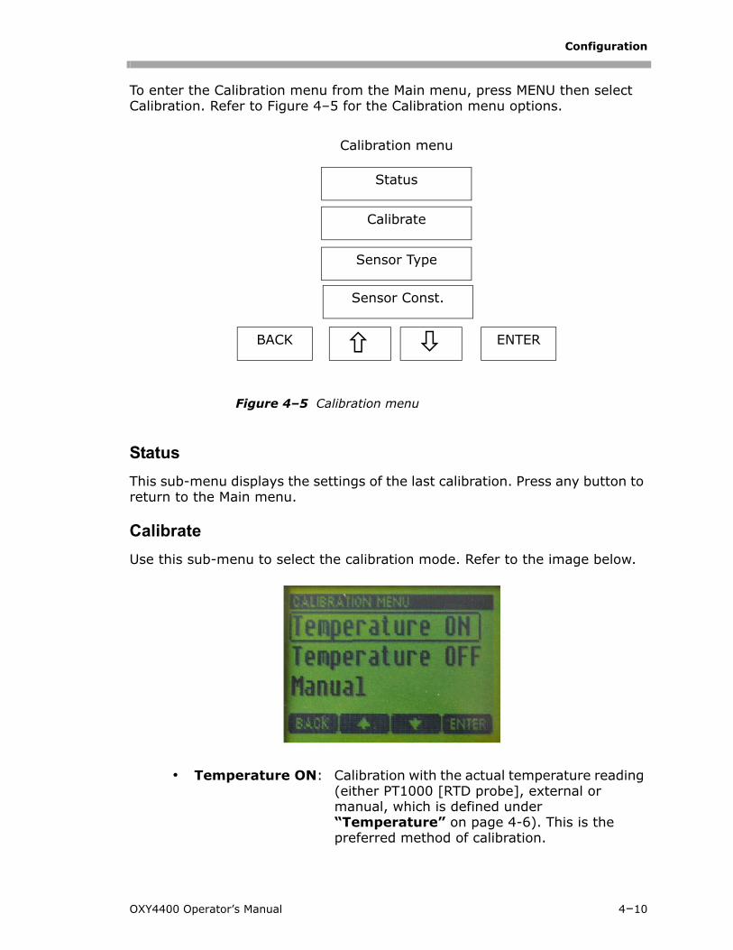
To enter the Calibration menu from the Main menu, press MENU then select Calibration. Refer to Figure 4–5 for the Calibration menu options.
Status
This sub-menu displays the settings of the last calibration. Press any button to return to the Main menu.
Calibrate
Use this sub-menu to select the calibration mode. Refer to the image below.
• Temperature ON: Calibration with the actual temperature reading (either PT1000 [RTD probe], external or manual, which is defined under “Temperature” on page 4-6). This is the preferred method of calibration.
Figure 4–5 Calibration menu
Calibration menu
Status
Calibrate
Sensor Type
BACK ENTER
Sensor Const.
OXY4400 Operator’s Manual 4–10
Oxygen Analyzer
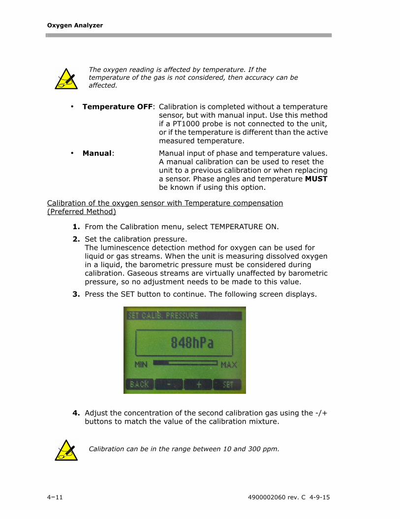
• Temperature OFF: Calibration is completed without a temperature sensor, but with manual input. Use this method if a PT1000 probe is not connected to the unit, or if the temperature is different than the active measured temperature.
• Manual: Manual input of phase and temperature values. A manual calibration can be used to reset the unit to a previous calibration or when replacing a sensor. Phase angles and temperature MUST be known if using this option.
Calibration of the oxygen sensor with Temperature compensation(Preferred Method)
1. From the Calibration menu, select TEMPERATURE ON.
2. Set the calibration pressure. The luminescence detection method for oxygen can be used for liquid or gas streams. When the unit is measuring dissolved oxygen in a liquid, the barometric pressure must be considered during calibration. Gaseous streams are virtually unaffected by barometric pressure, so no adjustment needs to be made to this value.
3. Press the SET button to continue. The following screen displays.
4. Adjust the concentration of the second calibration gas using the -/+ buttons to match the value of the calibration mixture.
The oxygen reading is affected by temperature. If the temperature of the gas is not considered, then accuracy can be affected.
Calibration can be in the range between 10 and 300 ppm.
4–11 4900002060 rev. C 4-9-15
Configuration
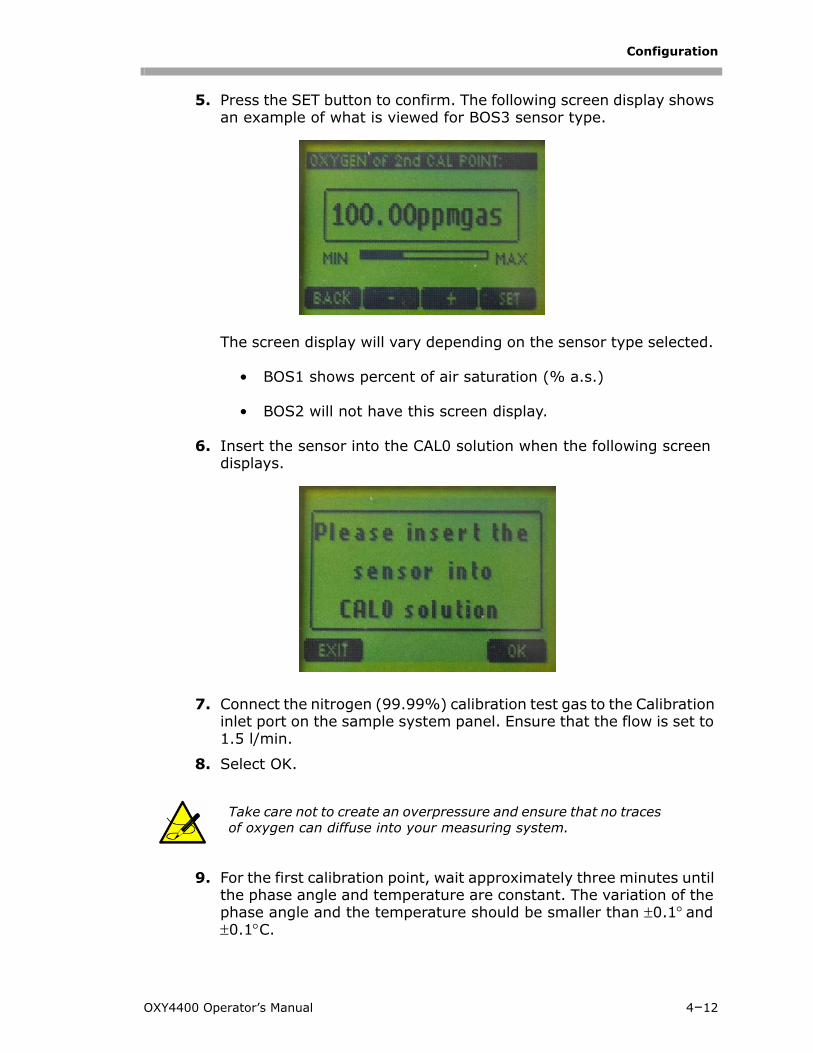
5. Press the SET button to confirm. The following screen display shows an example of what is viewed for BOS3 sensor type.
The screen display will vary depending on the sensor type selected.
• BOS1 shows percent of air saturation (% a.s.)
• BOS2 will not have this screen display.
6. Insert the sensor into the CAL0 solution when the following screen displays.
7. Connect the nitrogen (99.99%) calibration test gas to the Calibration inlet port on the sample system panel. Ensure that the flow is set to 1.5 l/min.
8. Select OK.
9. For the first calibration point, wait approximately three minutes until the phase angle and temperature are constant. The variation of the phase angle and the temperature should be smaller than 0.1 and 0.1C.
Take care not to create an overpressure and ensure that no traces of oxygen can diffuse into your measuring system.
OXY4400 Operator’s Manual 4–12
Oxygen Analyzer
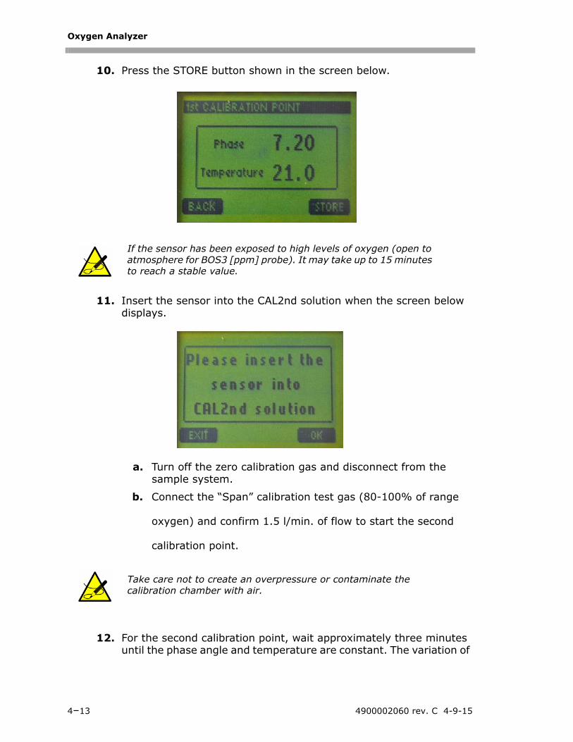
10. Press the STORE button shown in the screen below.
11. Insert the sensor into the CAL2nd solution when the screen below displays.
a. Turn off the zero calibration gas and disconnect from the sample system.
b. Connect the “Span” calibration test gas (80-100% of range
oxygen) and confirm 1.5 l/min. of flow to start the second
calibration point.
12. For the second calibration point, wait approximately three minutes until the phase angle and temperature are constant. The variation of
If the sensor has been exposed to high levels of oxygen (open to atmosphere for BOS3 [ppm] probe). It may take up to 15 minutes to reach a stable value.
Take care not to create an overpressure or contaminate the calibration chamber with air.
4–13 4900002060 rev. C 4-9-15
Configuration
OXY4400 Operator’s Manual 4–14
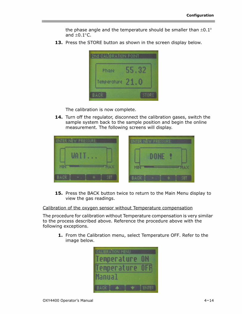
the phase angle and the temperature should be smaller than 0.1
and 0.1C.
13. Press the STORE button as shown in the screen display below.
The calibration is now complete.
14. Turn off the regulator, disconnect the calibration gases, switch the sample system back to the sample position and begin the online measurement. The following screens will display.
15. Press the BACK button twice to return to the Main Menu display to view the gas readings.
Calibration of the oxygen sensor without Temperature compensation
The procedure for calibration without Temperature compensation is very similar to the process described above. Reference the procedure above with the following exceptions.
1. From the Calibration menu, select Temperature OFF. Refer to the image below.
Oxygen Analyzer
2. Adjust the temperature (in C) of the calibration standards and confirm it by pressing the SET button.
3. Follow the remaining steps from the “Calibration of the oxygen sensor with Temperature compensation (Preferred Method)” on page 4-11.
Calibration of the oxygen sensor with Manual Temperature compensation
• Manual CalibrationUser-defined calibration should be applied if there is no possibility for adjusting the second calibration value via calibration test gas or if re-calibration of the sensor is not desired. SpectraSensors delivers a calibration report with each oxygen analyzer that provides two calibration values, which can be entered into the user-defined calibration mode.
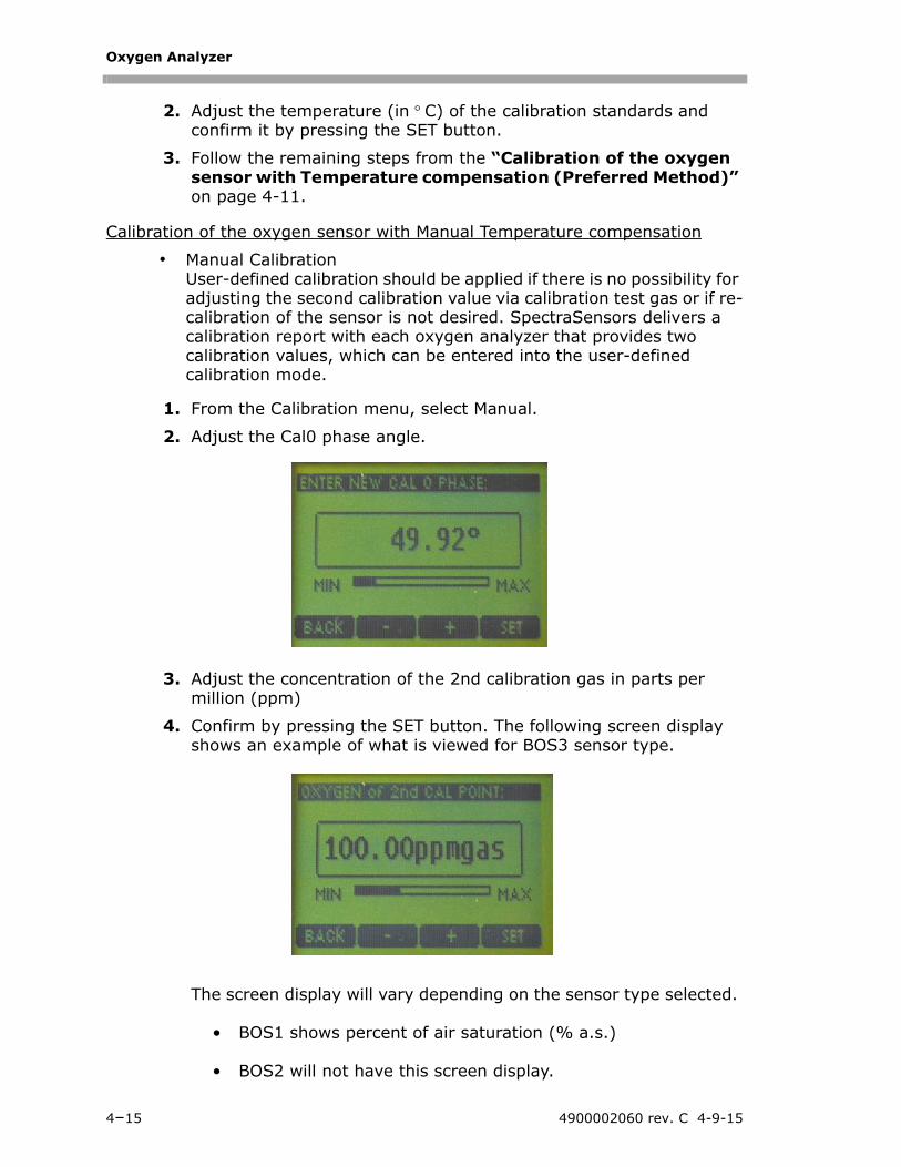
1. From the Calibration menu, select Manual.
2. Adjust the Cal0 phase angle.
3. Adjust the concentration of the 2nd calibration gas in parts per million (ppm)
4. Confirm by pressing the SET button. The following screen display shows an example of what is viewed for BOS3 sensor type.
The screen display will vary depending on the sensor type selected.
• BOS1 shows percent of air saturation (% a.s.)
• BOS2 will not have this screen display.
4–15 4900002060 rev. C 4-9-15
Configuration
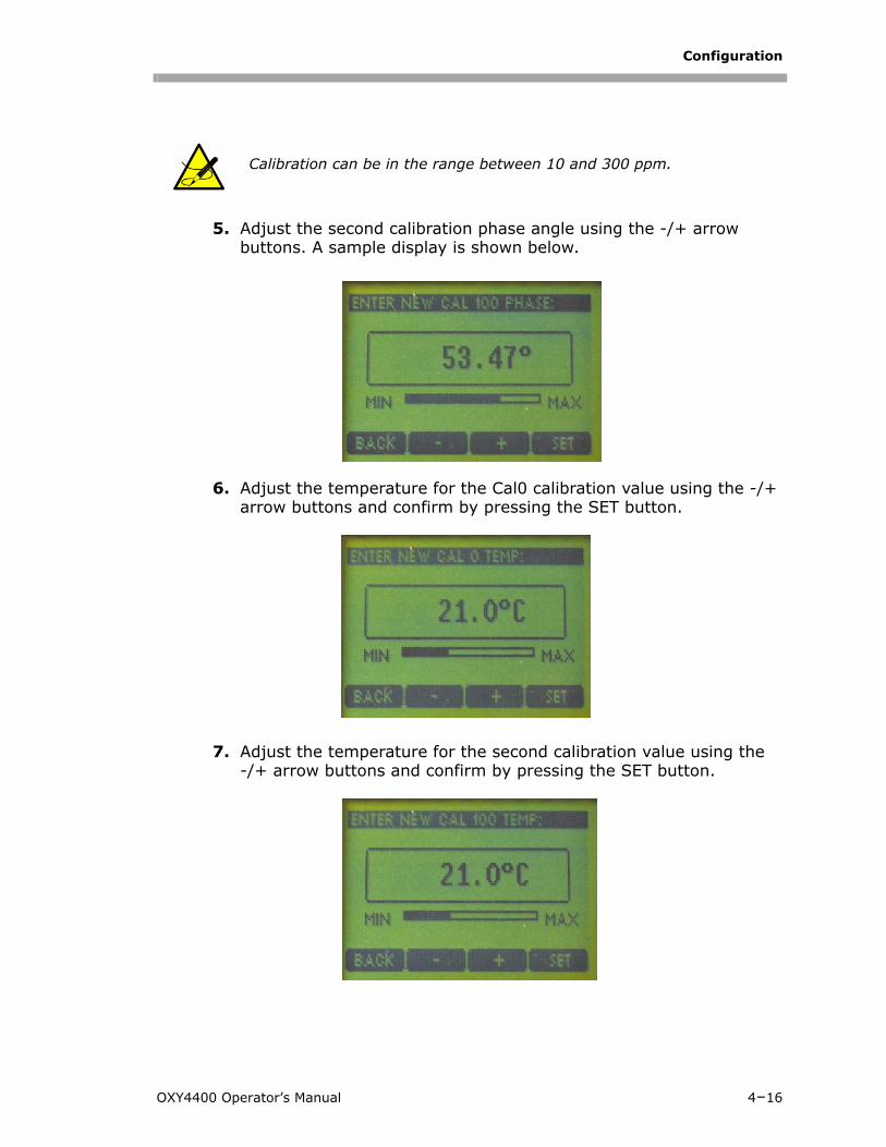
5. Adjust the second calibration phase angle using the -/+ arrow buttons. A sample display is shown below.
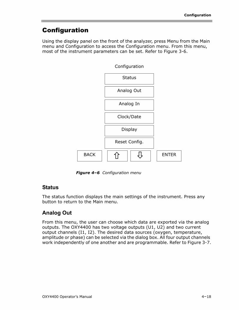
6. Adjust the temperature for the Cal0 calibration value using the -/+ arrow buttons and confirm by pressing the SET button.
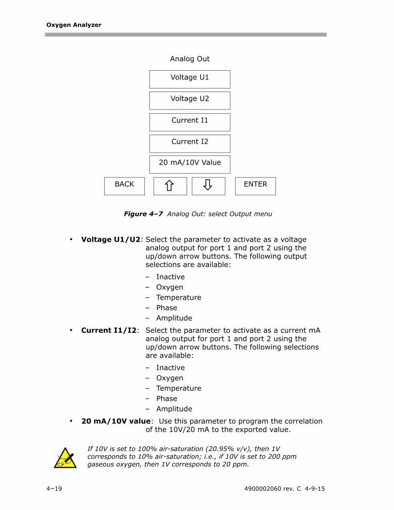
7. Adjust the temperature for the second calibration value using the -/+ arrow buttons and confirm by pressing the SET button.
Calibration can be in the range between 10 and 300 ppm.
OXY4400 Operator’s Manual 4–16

Oxygen Analyzer
8. To finish the manual calibration, adjust the atmospheric pressure using the -/+ arrow buttons and confirm by pressing the SET button.
Data LoggingBy default, the data logger is turned off. To start data logging, select Data Logging from the Main menu and START.
To stop the recording, select Data Logging and STOP.
The data logger status is available in Data Logging and Status, and shows details such as starting time and date, sampling rate, saved records and free memory space. The maximum recording time possible depends on the selected sampling rate. This is shown on the display after selecting START.
It is possible to turn off and restart the oxygen instrument with the Data Logger still activated. The data recording will continue immediately after the restart.
Stored records can be uploaded with the OXY4400 software that is supplied with the analyzer. For information on operating Data Logger through a PC terminal, refer to “PC Operations” on page 5-1.
During the recording (Data Logger activated), other functions cannot be selected from the Main menu.
When the data logging function is stopped and restarted, the previous records are overwritten.
4–17 4900002060 rev. C 4-9-15
Configuration
ConfigurationUsing the display panel on the front of the analyzer, press Menu from the Main menu and Configuration to access the Configuration menu. From this menu, most of the instrument parameters can be set. Refer to Figure 3-6.
Status
The status function displays the main settings of the instrument. Press any button to return to the Main menu.
Analog Out
From this menu, the user can choose which data are exported via the analog outputs. The OXY4400 has two voltage outputs (U1, U2) and two current output channels (I1, I2). The desired data sources (oxygen, temperature, amplitude or phase) can be selected via the dialog box. All four output channels work independently of one another and are programmable. Refer to Figure 3-7.
Figure 4–6 Configuration menu
Configuration
Status
Analog Out
Analog In
Clock/Date
BACK ENTER
Display
Reset Config.
OXY4400 Operator’s Manual 4–18
Oxygen Analyzer
• Voltage U1/U2: Select the parameter to activate as a voltage analog output for port 1 and port 2 using the up/down arrow buttons. The following output selections are available:
– Inactive– Oxygen– Temperature– Phase– Amplitude
• Current I1/I2: Select the parameter to activate as a current mA analog output for port 1 and port 2 using the up/down arrow buttons. The following selections are available:
– Inactive– Oxygen– Temperature– Phase– Amplitude
• 20 mA/10V value: Use this parameter to program the correlation of the 10V/20 mA to the exported value.
If 10V is set to 100% air-saturation (20.95% v/v), then 1V corresponds to 10% air-saturation; i.e., if 10V is set to 200 ppm gaseous oxygen, then 1V corresponds to 20 ppm.
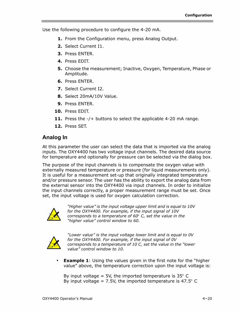
Figure 4–7 Analog Out: select Output menu
Analog Out
Voltage U1
Voltage U2
Current I1
Current I2
BACK ENTER
20 mA/10V Value
4–19 4900002060 rev. C 4-9-15
Configuration
Use the following procedure to configure the 4-20 mA.
1. From the Configuration menu, press Analog Output.
2. Select Current I1.
3. Press ENTER.
4. Press EDIT.
5. Choose the measurement; Inactive, Oxygen, Temperature, Phase or Amplitude.
6. Press ENTER.
7. Select Current I2.
8. Select 20mA/10V Value.
9. Press ENTER.
10. Press EDIT.
11. Press the -/+ buttons to select the applicable 4-20 mA range.
12. Press SET.
Analog In
At this parameter the user can select the data that is imported via the analog inputs. The OXY4400 has two voltage input channels. The desired data source for temperature and optionally for pressure can be selected via the dialog box.
The purpose of the input channels is to compensate the oxygen value with externally measured temperature or pressure (for liquid measurements only). It is useful for a measurement set-up that originally integrated temperature and/or pressure sensor. The user has the ability to export the analog data from the external sensor into the OXY4400 via input channels. In order to initialize the input channels correctly, a proper measurement range must be set. Once set, the input voltage is used for oxygen calculation correction.
• Example 1: Using the values given in the first note for the “higher value” above, the temperature correction upon the input voltage is:
By input voltage = 5V, the imported temperature is 35 CBy input voltage = 7.5V, the imported temperature is 47.5 C
“Higher value” is the input voltage upper limit and is equal to 10V for the OXY4400. For example, if the input signal of 10V corresponds to a temperature of 60 C, set the value in the “higher value” control window to 60.
“Lower value” is the input voltage lower limit and is equal to 0V for the OXY4400. For example, if the input signal of 0V corresponds to a temperature of 10 C, set the value in the “lower value” control window to 10.
OXY4400 Operator’s Manual 4–20
Oxygen Analyzer
• Example 2: Suppose that the input voltage of 0V is equal to 500hPa, and 10V is equal to 2000hPa.
By input voltage = 3.5V, the imported pressure is 1025hPaBy input voltage = 5V, the imported pressure is 1250hPaBy input voltage = 7.5V, the imported pressure is 1625hPa
Clock/Date
Use the “+” and NEXT button to adjust the clock and date information. Complete the change by pressing the SET button.
Display
Changes the backlight illumination of the display. The ‘Auto’ function turns on the illumination after pressing any button, and after a few seconds switches it back off.
Reset Config.
Sets all parameters defined in this sub-menu to default.
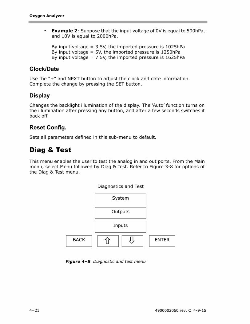
Diag & TestThis menu enables the user to test the analog in and out ports. From the Main menu, select Menu followed by Diag & Test. Refer to Figure 3-8 for options of the Diag & Test menu.
Figure 4–8 Diagnostic and test menu
Diagnostics and Test
System
Outputs
Inputs
BACK ENTER
4–21 4900002060 rev. C 4-9-15
Configuration
System
This menu displays the most important information of the instrument. Press any key to return to the Main menu.
Outputs
Select the channel to be tested using the up/down arrow buttons. Confirm the selection by pressing ENTER. Adjust the test output value and check the value with the external data logger or voltmeter.
Inputs
Select the channel to be tested using the up/down arrow buttons. Confirm the selection by pressing ENTER. The actual reading of the channel is displayed based on the input value.
OXY4400 Operator’s Manual 4–22

Oxygen Analyzer
THIS PAGE INTENTIONALLY LEFT BLANK
4–23 4900002060 rev. C 4-9-15
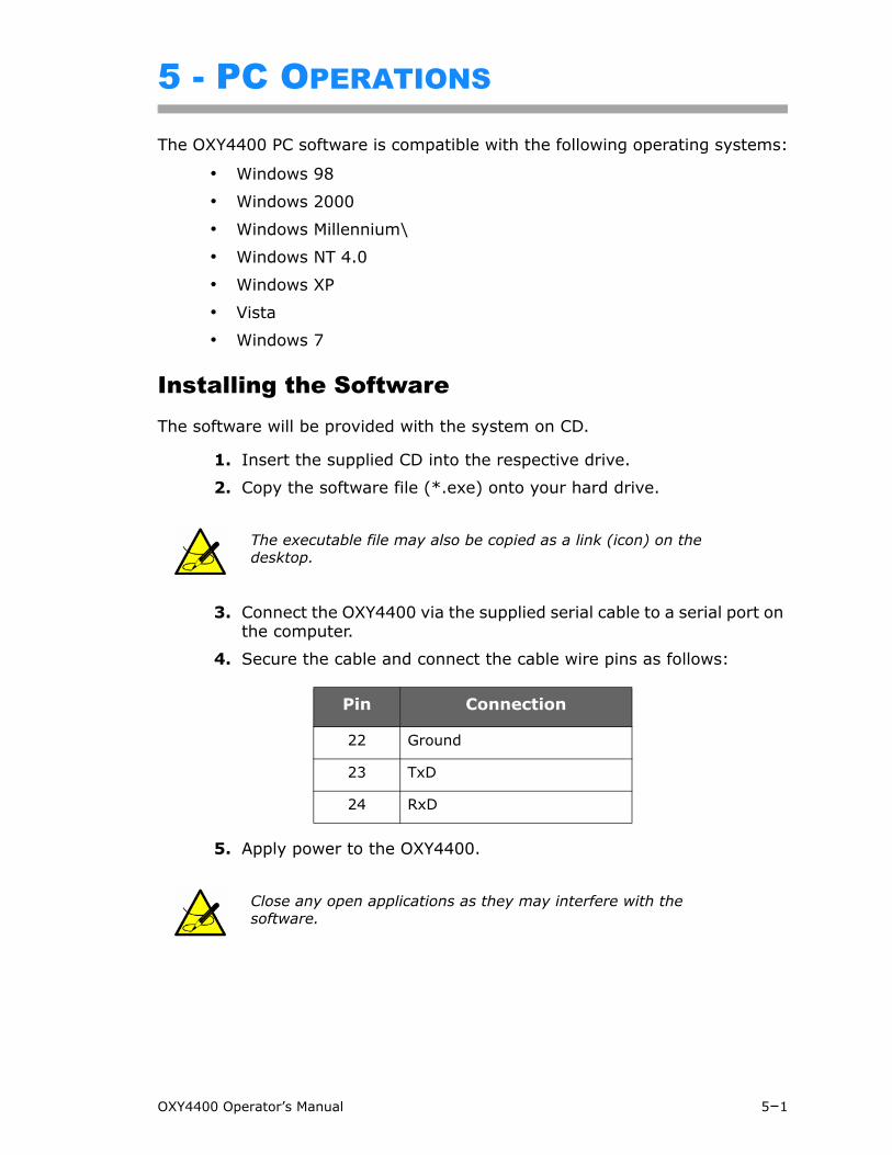
5 - PC OPERATIONS
The OXY4400 PC software is compatible with the following operating systems:
• Windows 98
• Windows 2000
• Windows Millennium\
• Windows NT 4.0
• Windows XP
• Vista
• Windows 7
Installing the SoftwareThe software will be provided with the system on CD.
1. Insert the supplied CD into the respective drive.
2. Copy the software file (*.exe) onto your hard drive.
3. Connect the OXY4400 via the supplied serial cable to a serial port on the computer.
4. Secure the cable and connect the cable wire pins as follows:
5. Apply power to the OXY4400.
The executable file may also be copied as a link (icon) on the desktop.
Pin Connection
22 Ground
23 TxD
24 RxD
Close any open applications as they may interfere with the software.
OXY4400 Operator’s Manual 5–1
Oxygen Analyzer
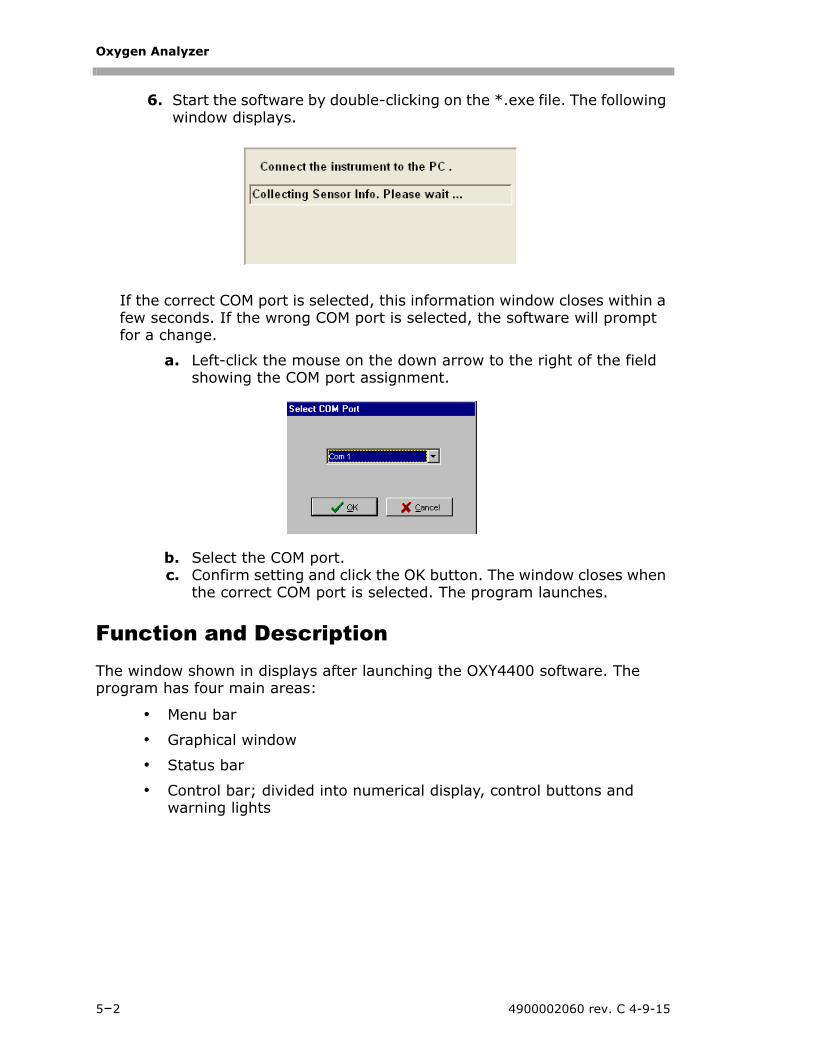
6. Start the software by double-clicking on the *.exe file. The following window displays.
If the correct COM port is selected, this information window closes within a few seconds. If the wrong COM port is selected, the software will prompt for a change.
a. Left-click the mouse on the down arrow to the right of the field showing the COM port assignment.
b. Select the COM port.c. Confirm setting and click the OK button. The window closes when
the correct COM port is selected. The program launches.
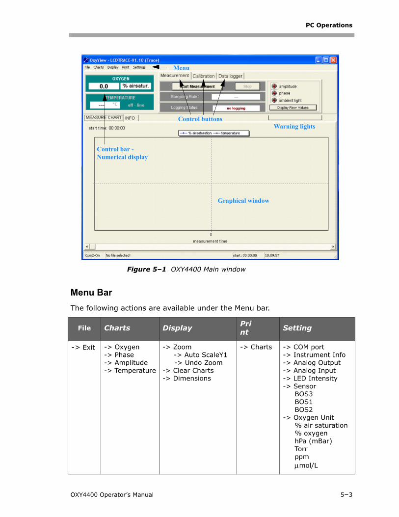
Function and Description The window shown in displays after launching the OXY4400 software. The program has four main areas:
• Menu bar
• Graphical window
• Status bar
• Control bar; divided into numerical display, control buttons and warning lights
5–2 4900002060 rev. C 4-9-15
PC Operations
Menu Bar
The following actions are available under the Menu bar.
File Charts Display Print Setting
-> Exit -> Oxygen-> Phase-> Amplitude-> Temperature
-> Zoom-> Auto ScaleY1-> Undo Zoom
-> Clear Charts-> Dimensions
-> Charts -> COM port-> Instrument Info-> Analog Output-> Analog Input-> LED Intensity-> Sensor
BOS3BOS1BOS2
-> Oxygen Unit% air saturation% oxygenhPa (mBar)Torrppmmol/L
Graphical window
Control bar - Numerical display
Control buttonsWarning lights
Menu
Figure 5–1 OXY4400 Main window
OXY4400 Operator’s Manual 5–3
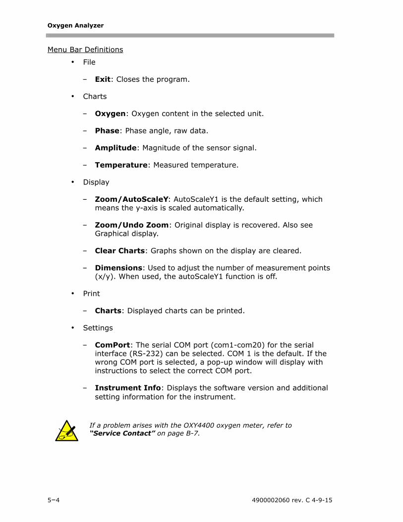
Oxygen Analyzer
Menu Bar Definitions
• File
– Exit: Closes the program.
• Charts
– Oxygen: Oxygen content in the selected unit.
– Phase: Phase angle, raw data.
– Amplitude: Magnitude of the sensor signal.
– Temperature: Measured temperature.
• Display
– Zoom/AutoScaleY: AutoScaleY1 is the default setting, which means the y-axis is scaled automatically.
– Zoom/Undo Zoom: Original display is recovered. Also see Graphical display.
– Clear Charts: Graphs shown on the display are cleared.
– Dimensions: Used to adjust the number of measurement points (x/y). When used, the autoScaleY1 function is off.
– Charts: Displayed charts can be printed.
• Settings
– ComPort: The serial COM port (com1-com20) for the serial interface (RS-232) can be selected. COM 1 is the default. If the wrong COM port is selected, a pop-up window will display with instructions to select the correct COM port.
– Instrument Info: Displays the software version and additional setting information for the instrument.
If a problem arises with the OXY4400 oxygen meter, refer to “Service Contact” on page B-7.
5–4 4900002060 rev. C 4-9-15
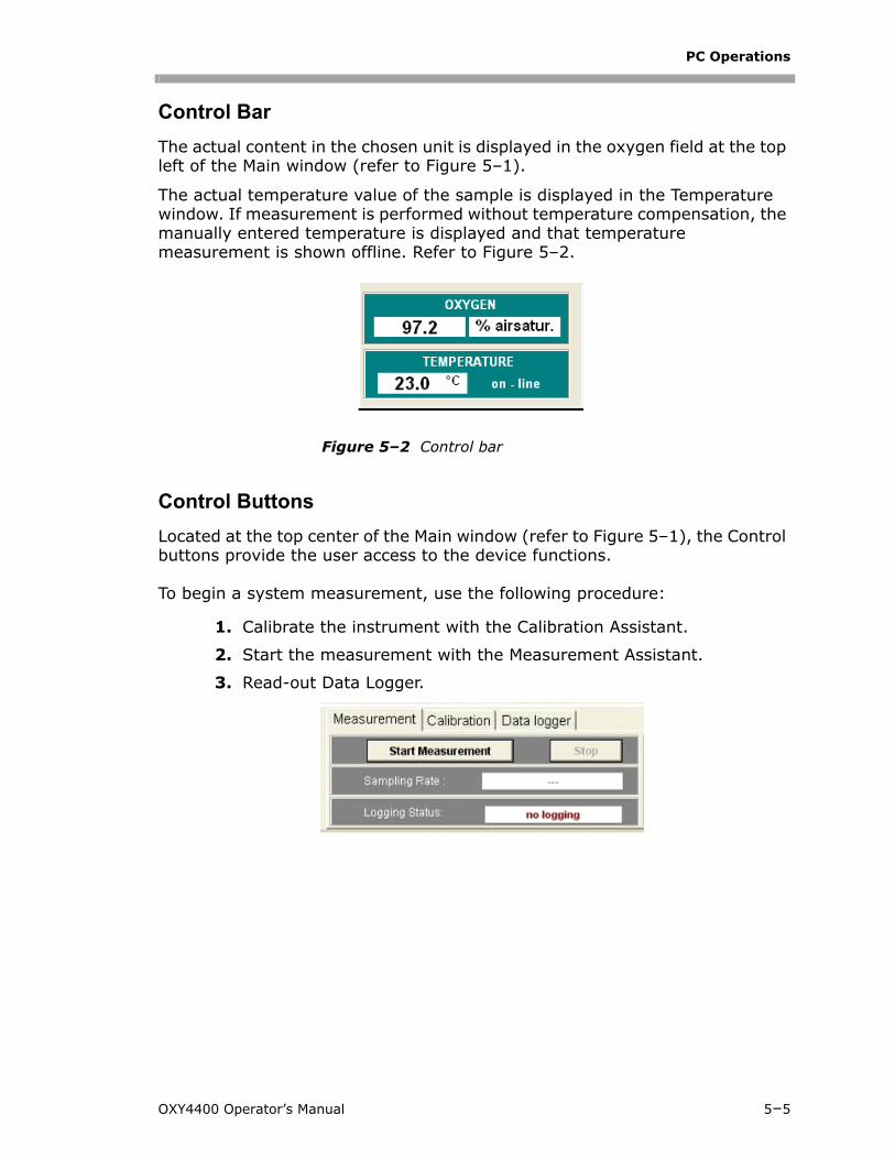
PC Operations
Control Bar
The actual content in the chosen unit is displayed in the oxygen field at the top left of the Main window (refer to Figure 5–1).
The actual temperature value of the sample is displayed in the Temperature window. If measurement is performed without temperature compensation, the manually entered temperature is displayed and that temperature measurement is shown offline. Refer to Figure 5–2.
Control Buttons
Located at the top center of the Main window (refer to Figure 5–1), the Control buttons provide the user access to the device functions.
To begin a system measurement, use the following procedure:
1. Calibrate the instrument with the Calibration Assistant.
2. Start the measurement with the Measurement Assistant.
3. Read-out Data Logger.
Figure 5–2 Control bar
OXY4400 Operator’s Manual 5–5
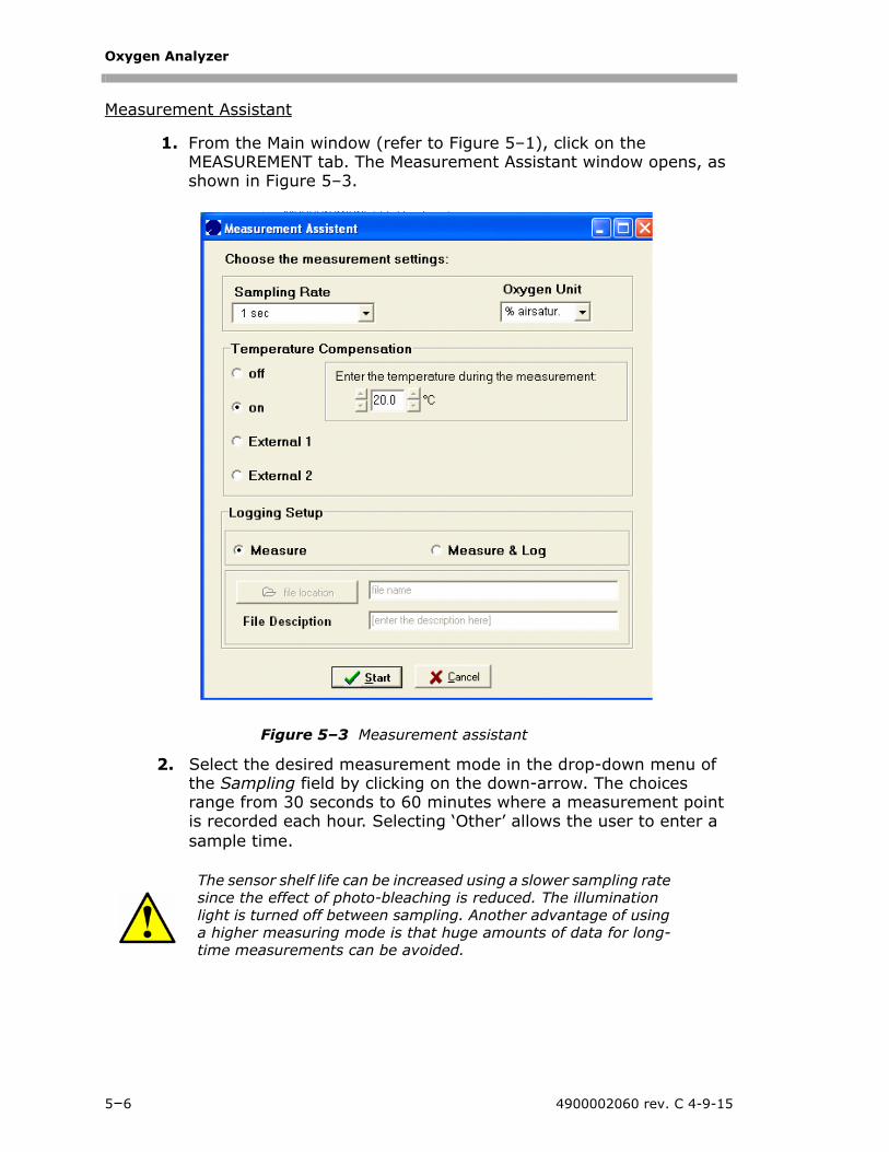
Oxygen Analyzer
Measurement Assistant
1. From the Main window (refer to Figure 5–1), click on the MEASUREMENT tab. The Measurement Assistant window opens, as shown in Figure 5–3.
2. Select the desired measurement mode in the drop-down menu of the Sampling field by clicking on the down-arrow. The choices range from 30 seconds to 60 minutes where a measurement point is recorded each hour. Selecting ‘Other’ allows the user to enter a sample time.
The sensor shelf life can be increased using a slower sampling rate since the effect of photo-bleaching is reduced. The illumination light is turned off between sampling. Another advantage of using a higher measuring mode is that huge amounts of data for long-time measurements can be avoided.
Figure 5–3 Measurement assistant
5–6 4900002060 rev. C 4-9-15
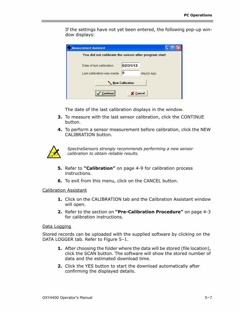
PC Operations
If the settings have not yet been entered, the following pop-up win-dow displays:
The date of the last calibration displays in the window.
3. To measure with the last sensor calibration, click the CONTINUE button.
4. To perform a sensor measurement before calibration, click the NEW CALIBRATION button.
5. Refer to “Calibration” on page 4-9 for calibration process instructions.
6. To exit from this menu, click on the CANCEL button.
Calibration Assistant
1. Click on the CALIBRATION tab and the Calibration Assistant window will open.
2. Refer to the section on “Pre-Calibration Procedure” on page 4-3 for calibration instructions.
Data Logging
Stored records can be uploaded with the supplied software by clicking on the DATA LOGGER tab. Refer to Figure 5–1.
1. After choosing the folder where the data will be stored (file location), click the SCAN button. The software will show the stored number of data and the estimated download time.
2. Click the YES button to start the download automatically after confirming the displayed details.
SpectraSensors strongly recommends performing a new sensor calibration to obtain reliable results.
OXY4400 Operator’s Manual 5–7
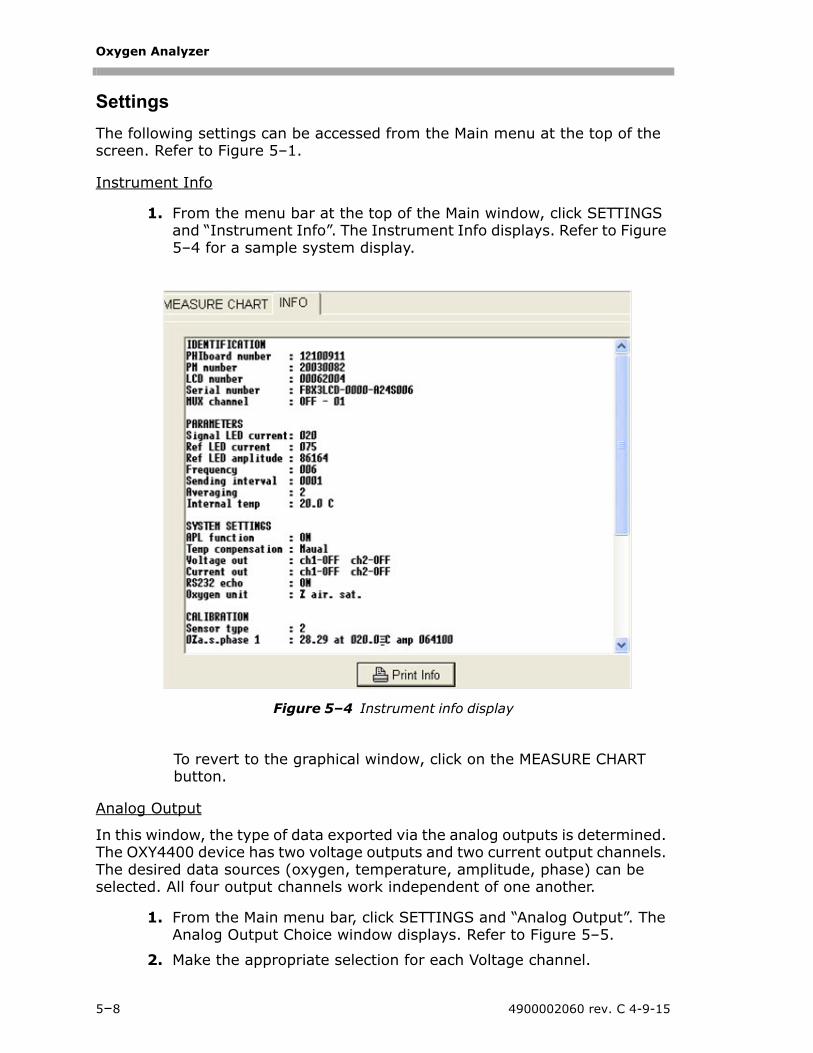
Oxygen Analyzer
Settings
The following settings can be accessed from the Main menu at the top of the screen. Refer to Figure 5–1.
Instrument Info
1. From the menu bar at the top of the Main window, click SETTINGS and “Instrument Info”. The Instrument Info displays. Refer to Figure 5–4 for a sample system display.
To revert to the graphical window, click on the MEASURE CHART button.
Analog Output
In this window, the type of data exported via the analog outputs is determined. The OXY4400 device has two voltage outputs and two current output channels. The desired data sources (oxygen, temperature, amplitude, phase) can be selected. All four output channels work independent of one another.
1. From the Main menu bar, click SETTINGS and “Analog Output”. The Analog Output Choice window displays. Refer to Figure 5–5.
2. Make the appropriate selection for each Voltage channel.
Figure 5–4 Instrument info display
5–8 4900002060 rev. C 4-9-15
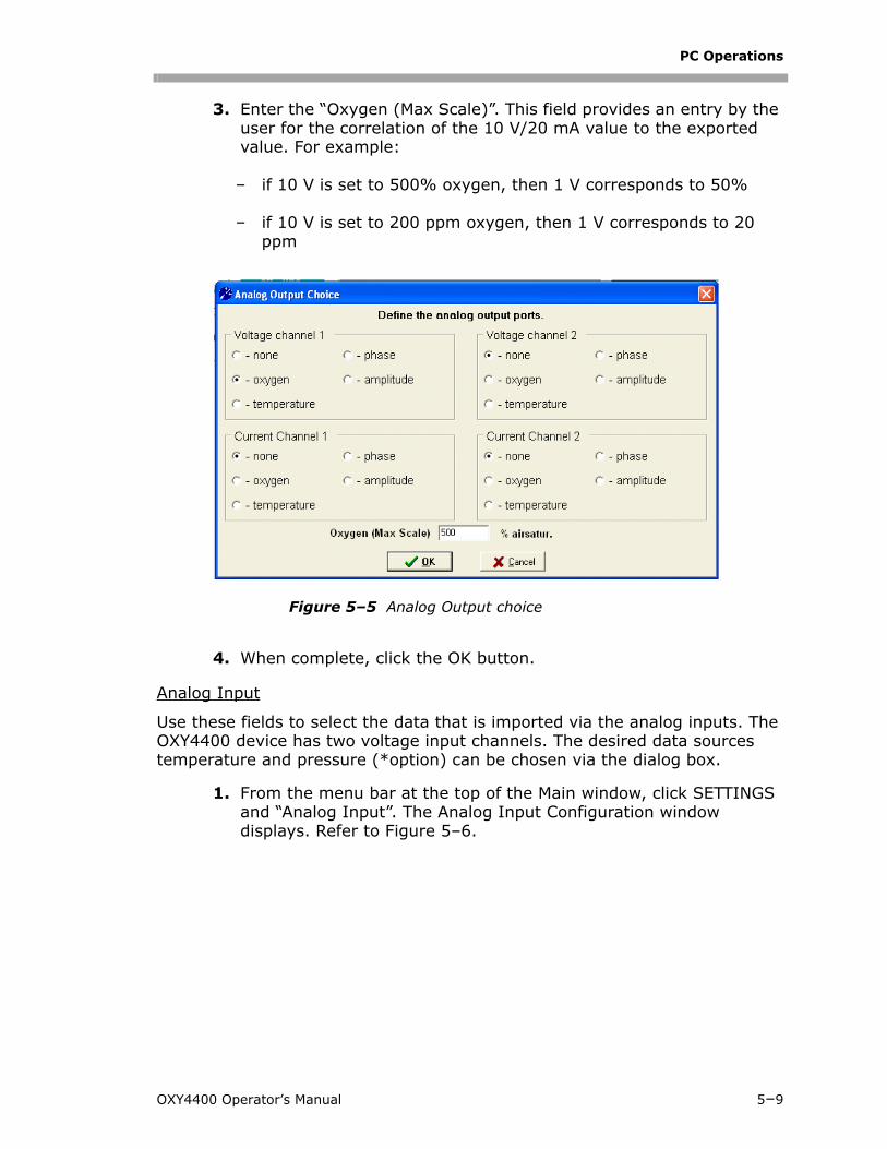
PC Operations
3. Enter the “Oxygen (Max Scale)”. This field provides an entry by the user for the correlation of the 10 V/20 mA value to the exported value. For example:
– if 10 V is set to 500% oxygen, then 1 V corresponds to 50%
– if 10 V is set to 200 ppm oxygen, then 1 V corresponds to 20 ppm
4. When complete, click the OK button.
Analog Input
Use these fields to select the data that is imported via the analog inputs. The OXY4400 device has two voltage input channels. The desired data sources temperature and pressure (*option) can be chosen via the dialog box.
1. From the menu bar at the top of the Main window, click SETTINGS and “Analog Input”. The Analog Input Configuration window displays. Refer to Figure 5–6.
Figure 5–5 Analog Output choice
OXY4400 Operator’s Manual 5–9
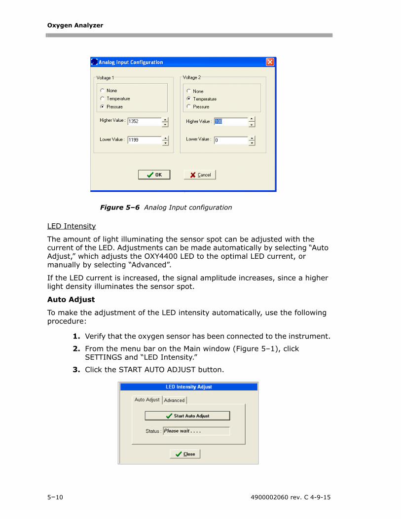
Oxygen Analyzer
LED Intensity
The amount of light illuminating the sensor spot can be adjusted with the current of the LED. Adjustments can be made automatically by selecting “Auto Adjust,” which adjusts the OXY4400 LED to the optimal LED current, or manually by selecting “Advanced”.
If the LED current is increased, the signal amplitude increases, since a higher light density illuminates the sensor spot.
Auto Adjust
To make the adjustment of the LED intensity automatically, use the following procedure:
1. Verify that the oxygen sensor has been connected to the instrument.
2. From the menu bar on the Main window (Figure 5–1), click SETTINGS and “LED Intensity.”
3. Click the START AUTO ADJUST button.
Figure 5–6 Analog Input configuration
5–10 4900002060 rev. C 4-9-15
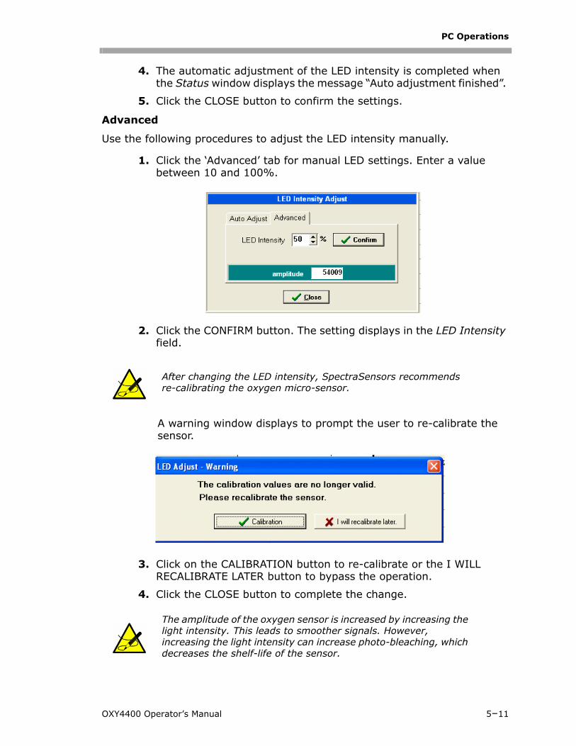
PC Operations
4. The automatic adjustment of the LED intensity is completed when the Status window displays the message “Auto adjustment finished”.
5. Click the CLOSE button to confirm the settings.
Advanced
Use the following procedures to adjust the LED intensity manually.
1. Click the ‘Advanced’ tab for manual LED settings. Enter a value between 10 and 100%.
2. Click the CONFIRM button. The setting displays in the LED Intensity field.
A warning window displays to prompt the user to re-calibrate the sensor.
3. Click on the CALIBRATION button to re-calibrate or the I WILL RECALIBRATE LATER button to bypass the operation.
4. Click the CLOSE button to complete the change.
After changing the LED intensity, SpectraSensors recommends re-calibrating the oxygen micro-sensor.
The amplitude of the oxygen sensor is increased by increasing the light intensity. This leads to smoother signals. However, increasing the light intensity can increase photo-bleaching, which decreases the shelf-life of the sensor.
OXY4400 Operator’s Manual 5–11
Oxygen Analyzer
Oxygen Unit
This is used to adjust the desired oxygen unit.
1. From the Main menu bar, click SETTINGS and “Oxygen Unit.”
2. Click on the down-arrow to the right of the field to select the unit to be used.
Temperature compensated oxygen measurements
To measure with temperature compensation, use the following procedure:
1. Verify that the temperature sensor PT1000 (RTD probe) is connected to the OXY4400.
2. Click on the ON radio button in the Temperature Compensation fields of the Oxygen Unit window.
3. Click the START button to begin measurement.
To measure without temperature compensation, follow the steps below:
1. Click on the OFF radio button in the Temperature Compensation fields of the Oxygen Unit window.
2. Manually enter the temperature during the measurement in the field.
3. Click the START button to begin measurement.
External Temperature Compensation
If the analog input channels are already configured (refer to “Analog Input” on page 5-9), the user can activate temperature compensation by externally importing the value. Here, channel 1 or 2 can be selected.
The field for entering a measurement temperature will be disabled if this function is selected.
The temperature will be measured in degrees Celsius.
Before starting the external compensation, check the quality of the electrical signals. This can be done when the OXY4400 is NOT in PC mode. The input voltage can be controlled directly on the LCD by entering “Diag & Test/Analog In.
5–12 4900002060 rev. C 4-9-15
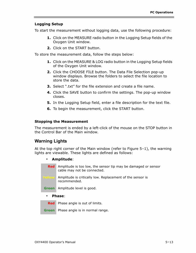
PC Operations
Logging Setup
To start the measurement without logging data, use the following procedure:
1. Click on the MEASURE radio button in the Logging Setup fields of the Oxygen Unit window.
2. Click on the START button.
To store the measurement data, follow the steps below:
1. Click on the MEASURE & LOG radio button in the Logging Setup fields of the Oxygen Unit window.
2. Click the CHOOSE FILE button. The Data File Selection pop-up window displays. Browse the folders to select the file location to store the data.
3. Select “.txt” for the file extension and create a file name.
4. Click the SAVE button to confirm the settings. The pop-up window closes.
5. In the Logging Setup field, enter a file description for the text file.
6. To begin the measurement, click the START button.
Stopping the Measurement
The measurement is ended by a left-click of the mouse on the STOP button in the Control Bar of the Main window.
Warning Lights
At the top right corner of the Main window (refer to Figure 5–1), the warning lights are viewable. These lights are defined as follows:
• Amplitude:
• Phase:
Red Amplitude is too low, the sensor tip may be damaged or sensor cable may not be connected.
Yellow Amplitude is critically low. Replacement of the sensor is recommended.
Green Amplitude level is good.
Red Phase angle is out of limits.
Green Phase angle is in normal range.
OXY4400 Operator’s Manual 5–13
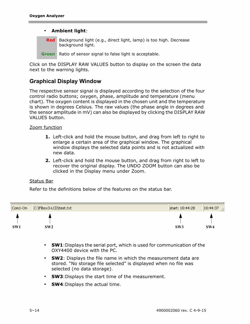
Oxygen Analyzer
SW1 4
• Ambient light:
Click on the DISPLAY RAW VALUES button to display on the screen the data next to the warning lights.
Graphical Display Window
The respective sensor signal is displayed according to the selection of the four control radio buttons; oxygen, phase, amplitude and temperature (menu chart). The oxygen content is displayed in the chosen unit and the temperature is shown in degrees Celsius. The raw values (the phase angle in degrees and the sensor amplitude in mV) can also be displayed by clicking the DISPLAY RAW VALUES button.
Zoom function
1. Left-click and hold the mouse button, and drag from left to right to enlarge a certain area of the graphical window. The graphical window displays the selected data points and is not actualized with new data.
2. Left-click and hold the mouse button, and drag from right to left to recover the original display. The UNDO ZOOM button can also be clicked in the Display menu under Zoom.
Status Bar
Refer to the definitions below of the features on the status bar.
• SW1:Displays the serial port, which is used for communication of the OXY4400 device with the PC.
• SW2: Displays the file name in which the measurement data are stored. “No storage file selected” is displayed when no file was selected (no data storage).
• SW3:Displays the start time of the measurement.
• SW4:Displays the actual time.
Red Background light (e.g., direct light, lamp) is too high. Decrease background light.
Green Ratio of sensor signal to false light is acceptable.
SW2 SW3 SW
5–14 4900002060 rev. C 4-9-15
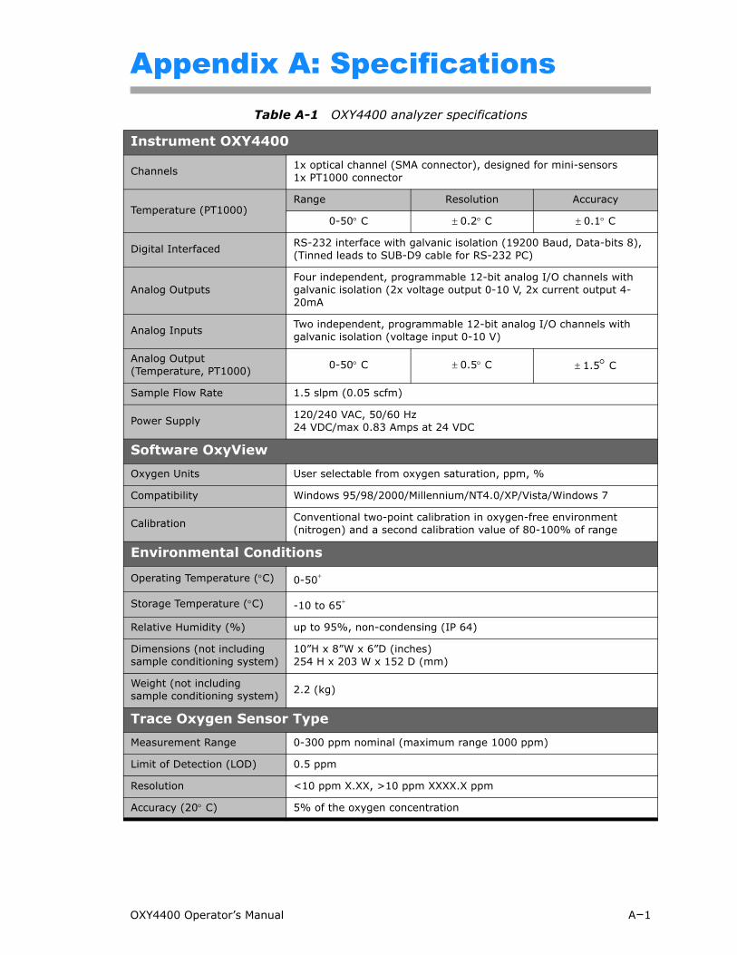
Appendix A: Specifications Table A-1 OXY4400 analyzer specifications
Instrument OXY4400
Channels 1x optical channel (SMA connector), designed for mini-sensors1x PT1000 connector
Temperature (PT1000)Range Resolution Accuracy
0-50 C 0.2 C 0.1 C
Digital Interfaced RS-232 interface with galvanic isolation (19200 Baud, Data-bits 8), (Tinned leads to SUB-D9 cable for RS-232 PC)
Analog OutputsFour independent, programmable 12-bit analog I/O channels with galvanic isolation (2x voltage output 0-10 V, 2x current output 4-20mA
Analog Inputs Two independent, programmable 12-bit analog I/O channels with galvanic isolation (voltage input 0-10 V)
Analog Output (Temperature, PT1000) 0-50 C 0.5 C 1.5 C
Sample Flow Rate 1.5 slpm (0.05 scfm)
Power Supply 120/240 VAC, 50/60 Hz24 VDC/max 0.83 Amps at 24 VDC
Software OxyViewOxygen Units User selectable from oxygen saturation, ppm, %
Compatibility Windows 95/98/2000/Millennium/NT4.0/XP/Vista/Windows 7
Calibration Conventional two-point calibration in oxygen-free environment (nitrogen) and a second calibration value of 80-100% of range
Environmental Conditions
Operating Temperature (C) 0-50
Storage Temperature (C) -10 to 65
Relative Humidity (%) up to 95%, non-condensing (IP 64)
Dimensions (not including sample conditioning system)
10”H x 8”W x 6”D (inches)254 H x 203 W x 152 D (mm)
Weight (not including sample conditioning system) 2.2 (kg)
Trace Oxygen Sensor TypeMeasurement Range 0-300 ppm nominal (maximum range 1000 ppm)
Limit of Detection (LOD) 0.5 ppm
Resolution <10 ppm X.XX, >10 ppm XXXX.X ppm
Accuracy (20 C) 5% of the oxygen concentration
OXY4400 Operator’s Manual A–1
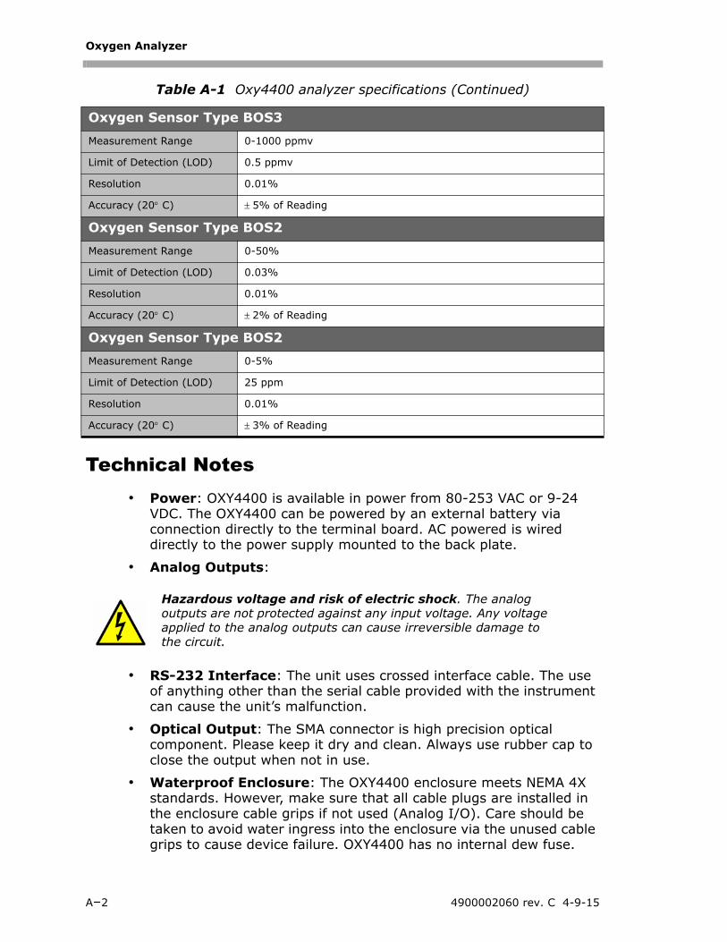
Oxygen Analyzer
Table A-1 Oxy4400 analyzer specifications (Continued)
Technical Notes• Power: OXY4400 is available in power from 80-253 VAC or 9-24
VDC. The OXY4400 can be powered by an external battery via connection directly to the terminal board. AC powered is wired directly to the power supply mounted to the back plate.
• Analog Outputs:
• RS-232 Interface: The unit uses crossed interface cable. The use of anything other than the serial cable provided with the instrument can cause the unit’s malfunction.
• Optical Output: The SMA connector is high precision optical component. Please keep it dry and clean. Always use rubber cap to close the output when not in use.
• Waterproof Enclosure: The OXY4400 enclosure meets NEMA 4X standards. However, make sure that all cable plugs are installed in the enclosure cable grips if not used (Analog I/O). Care should be taken to avoid water ingress into the enclosure via the unused cable grips to cause device failure. OXY4400 has no internal dew fuse.
Oxygen Sensor Type BOS3Measurement Range 0-1000 ppmv
Limit of Detection (LOD) 0.5 ppmv
Resolution 0.01%
Accuracy (20 C) 5% of Reading
Oxygen Sensor Type BOS2Measurement Range 0-50%
Limit of Detection (LOD) 0.03%
Resolution 0.01%
Accuracy (20 C) 2% of Reading
Oxygen Sensor Type BOS2Measurement Range 0-5%
Limit of Detection (LOD) 25 ppm
Resolution 0.01%
Accuracy (20 C) 3% of Reading
Hazardous voltage and risk of electric shock. The analog outputs are not protected against any input voltage. Any voltage applied to the analog outputs can cause irreversible damage to the circuit.
A–2 4900002060 rev. C 4-9-15

Specifications
• Approvals: The OXY4400 has been approved for use in Hazardous locations by FM and tested according to the NEC standards for Class 1, Division 2, Groups A, B, C and D for use in the U.S. and Canada.
For a complete listing of new or updated certificates, please visit the product page at www.spectrasensors.com.
OXY4400 Operator’s Manual A–3
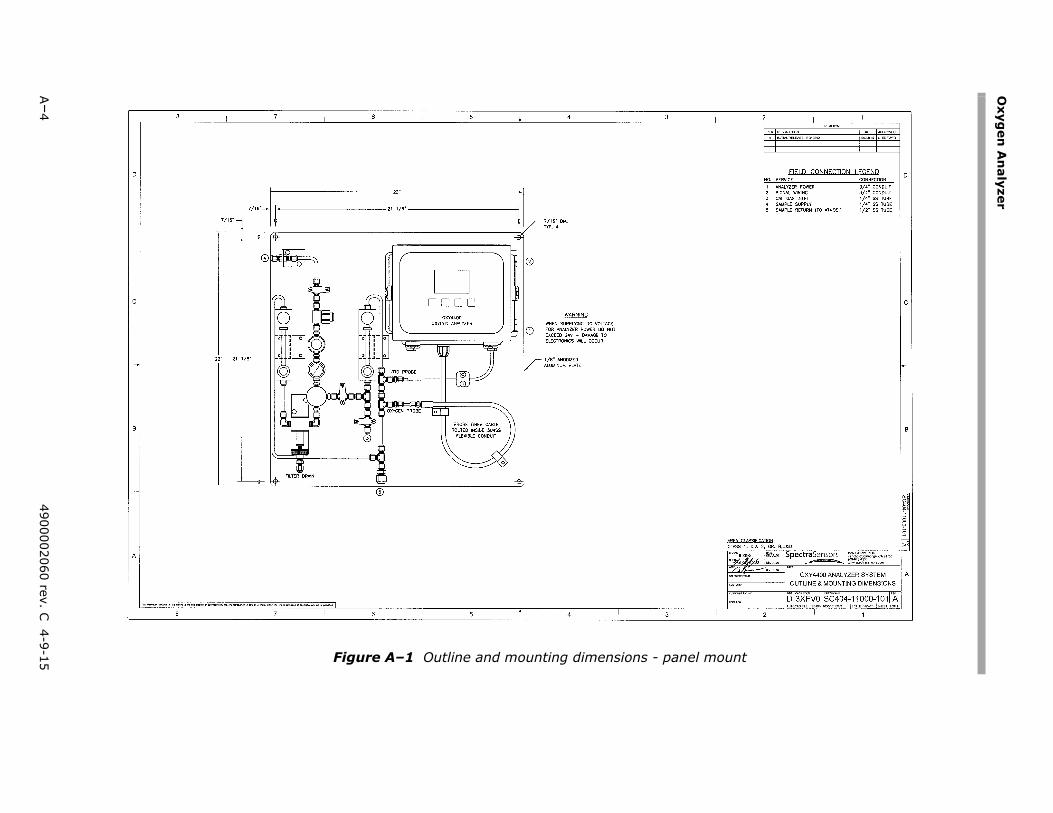
Oxyg
en A
nalyzer
A–4
4900002060 rev. C 4-9-15 el mount
Figure A–1 Outline and mounting dimensions - pan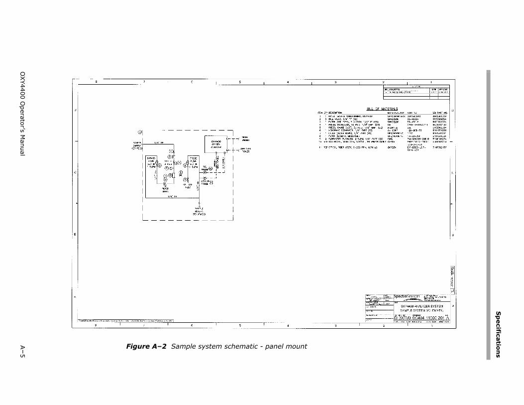
Sp
ecifications
OXY4400 O
perator’s Manual
A–5
Figure A–2 Sample system schematic - panel mount
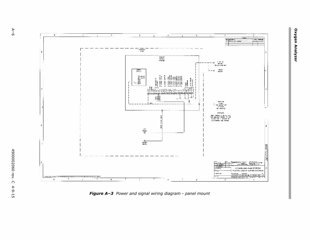
Oxyg
en A
nalyzer
A–6
4900002060 rev. C 4-9-15 unt
Figure A–3 Power and signal wiring diagram - panel mo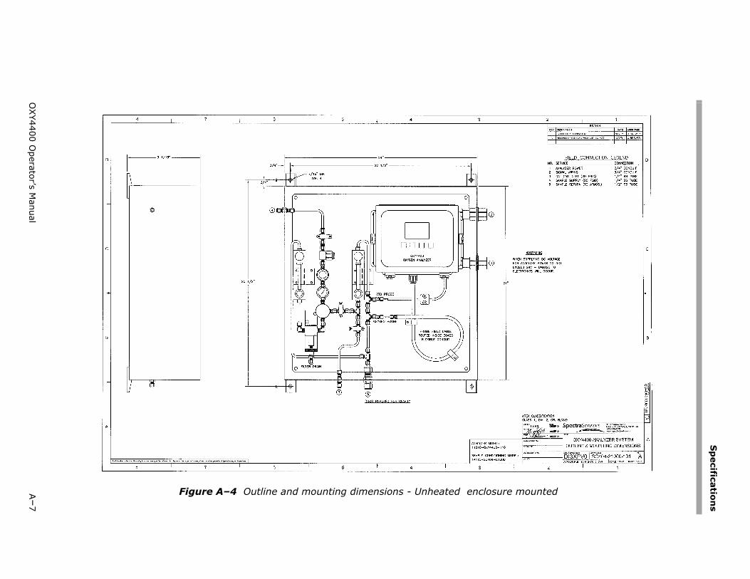
Sp
ecifications
OXY4400 O
perator’s Manual
A–7
ounted
Figure A–4 Outline and mounting dimensions - Unheated enclosure m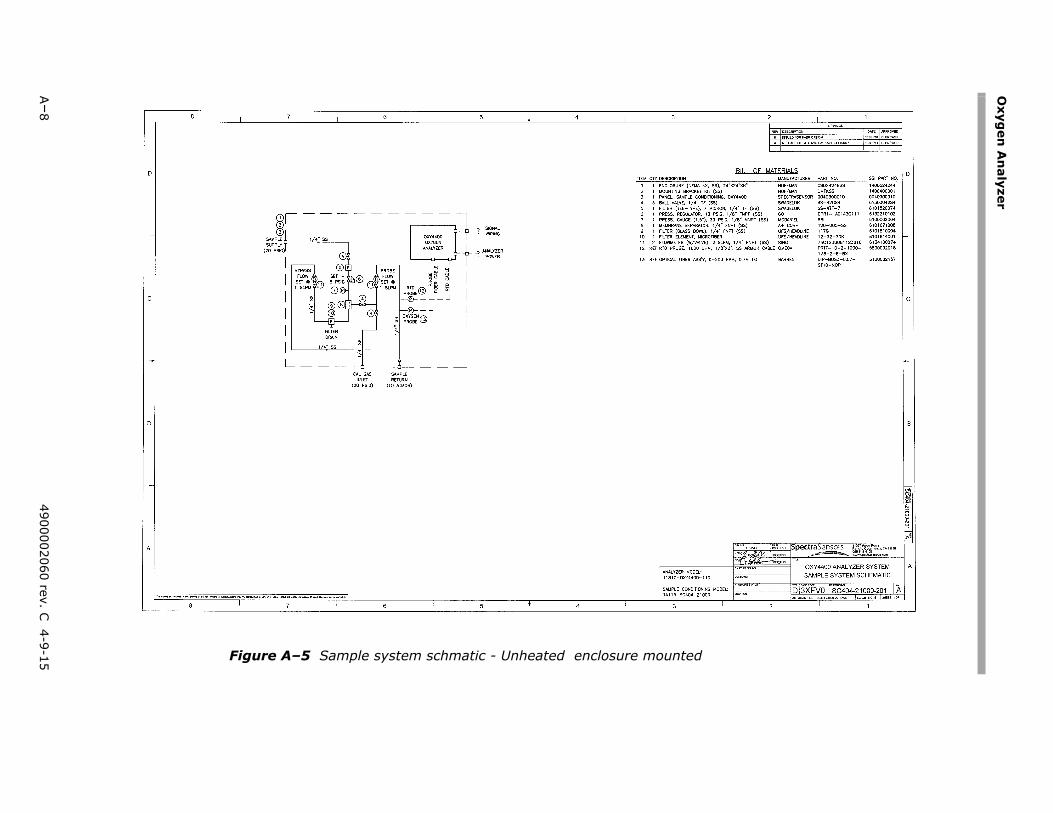
Oxyg
en A
nalyzer
A–8
4900002060 rev. C 4-9-15 ed
Figure A–5 Sample system schmatic - Unheated enclosure mount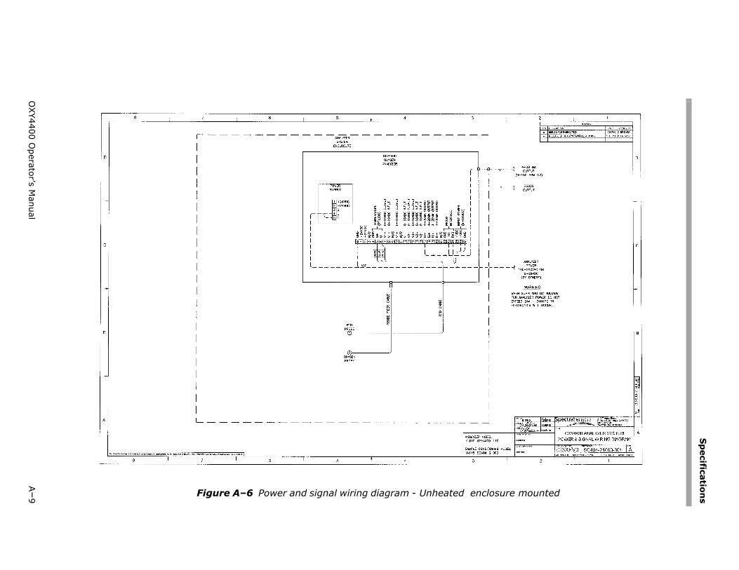
Sp
ecifications
OXY4400 O
perator’s Manual
A–9 mounted
Figure A–6 Power and signal wiring diagram - Unheated enclosure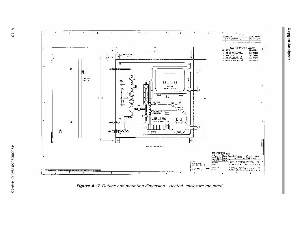
Oxyg
en A
nalyzer
A–10
4900002060 rev. C 4-9-15
ure mounted
Figure A–7 Outline and mounting dimension - Heated enclos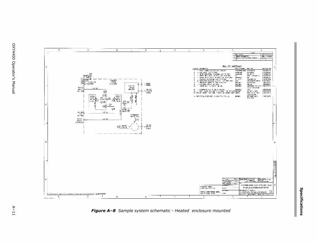
Sp
ecifications
OXY4400 O
perator’s Manual
A–11 nted
Figure A–8 Sample system schematic - Heated enclosure mou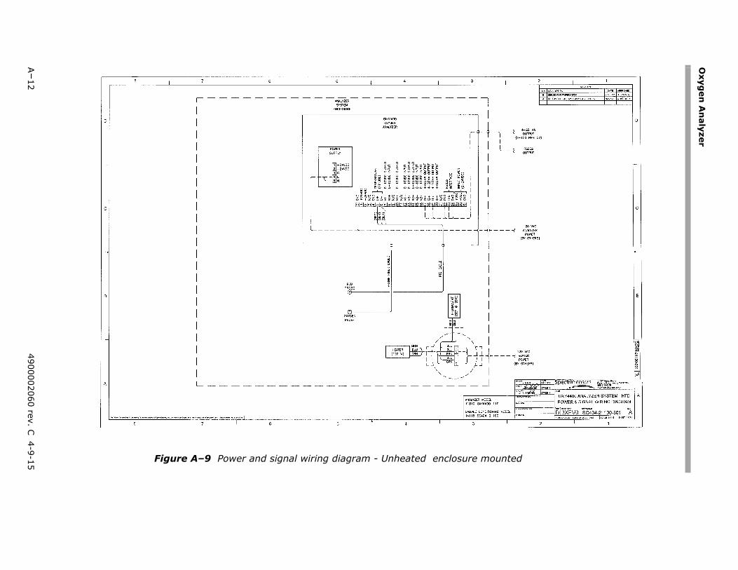
Oxyg
en A
nalyzer
A–12
4900002060 rev. C 4-9-15 mounted
Figure A–9 Power and signal wiring diagram - Unheated enclosure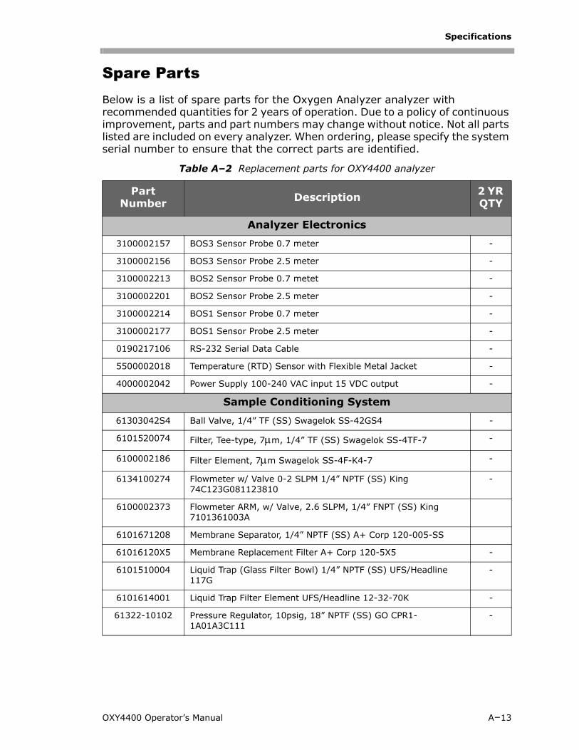
Specifications
Spare PartsBelow is a list of spare parts for the Oxygen Analyzer analyzer with recommended quantities for 2 years of operation. Due to a policy of continuous improvement, parts and part numbers may change without notice. Not all parts listed are included on every analyzer. When ordering, please specify the system serial number to ensure that the correct parts are identified.
Table A–2 Replacement parts for OXY4400 analyzer
Part Number Description 2 YR
QTY
Analyzer Electronics
3100002157 BOS3 Sensor Probe 0.7 meter -
3100002156 BOS3 Sensor Probe 2.5 meter -
3100002213 BOS2 Sensor Probe 0.7 metet -
3100002201 BOS2 Sensor Probe 2.5 meter -
3100002214 BOS1 Sensor Probe 0.7 meter -
3100002177 BOS1 Sensor Probe 2.5 meter -
0190217106 RS-232 Serial Data Cable -
5500002018 Temperature (RTD) Sensor with Flexible Metal Jacket -
4000002042 Power Supply 100-240 VAC input 15 VDC output -
Sample Conditioning System
61303042S4 Ball Valve, 1/4” TF (SS) Swagelok SS-42GS4 -
6101520074 Filter, Tee-type, 7m, 1/4” TF (SS) Swagelok SS-4TF-7 -
6100002186 Filter Element, 7m Swagelok SS-4F-K4-7 -
6134100274 Flowmeter w/ Valve 0-2 SLPM 1/4” NPTF (SS) King 74C123G081123810
-
6100002373 Flowmeter ARM, w/ Valve, 2.6 SLPM, 1/4” FNPT (SS) King 7101361003A
6101671208 Membrane Separator, 1/4” NPTF (SS) A+ Corp 120-005-SS
61016120X5 Membrane Replacement Filter A+ Corp 120-5X5 -
6101510004 Liquid Trap (Glass Filter Bowl) 1/4” NPTF (SS) UFS/Headline 117G
-
6101614001 Liquid Trap Filter Element UFS/Headline 12-32-70K -
61322-10102 Pressure Regulator, 10psig, 18” NPTF (SS) GO CPR1-1A01A3C111
-
OXY4400 Operator’s Manual A–13
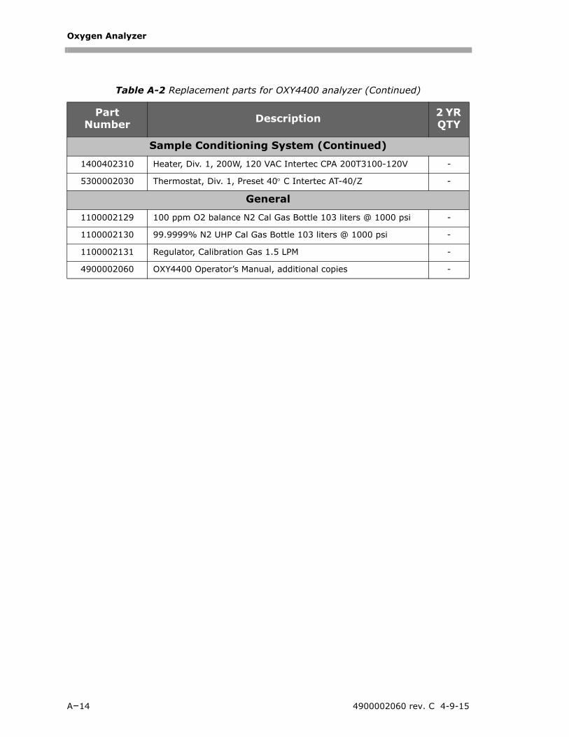
Oxygen Analyzer
Table A-2 Replacement parts for OXY4400 analyzer (Continued)
Part Number Description 2 YR
QTY
Sample Conditioning System (Continued)
1400402310 Heater, Div. 1, 200W, 120 VAC Intertec CPA 200T3100-120V -
5300002030 Thermostat, Div. 1, Preset 40 C Intertec AT-40/Z -
General
1100002129 100 ppm O2 balance N2 Cal Gas Bottle 103 liters @ 1000 psi -
1100002130 99.9999% N2 UHP Cal Gas Bottle 103 liters @ 1000 psi -
1100002131 Regulator, Calibration Gas 1.5 LPM -
4900002060 OXY4400 Operator’s Manual, additional copies -
A–14 4900002060 rev. C 4-9-15
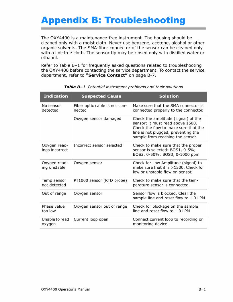
Appendix B: Troubleshooting
The OXY4400 is a maintenance-free instrument. The housing should be cleaned only with a moist cloth. Never use benzene, acetone, alcohol or other organic solvents. The SMA-fiber connector of the sensor can be cleaned only with a lint-free cloth. The sensor tip may be rinsed only with distilled water or ethanol.
Refer to Table B–1 for frequently asked questions related to troubleshooting the OXY4400 before contacting the service department. To contact the service department, refer to “Service Contact” on page B-7.
Table B–1 Potential instrument problems and their solutions
Indication Suspected Cause Solution
No sensor detected
Fiber optic cable is not con-nected
Make sure that the SMA connector is connected properly to the connector.
Oxygen sensor damaged Check the amplitude (signal) of the sensor; it must read above 1500. Check the flow to make sure that the line is not plugged, preventing the sample from reaching the sensor.
Oxygen read-ings incorrect
Incorrect sensor selected Check to make sure that the proper sensor is selected: BOS1, 0-5%; BOS2, 0-50%; BOS3, 0-1000 ppm
Oxygen read-ing unstable
Oxygen sensor Check for Low Amplitude (signal) to make sure that it is >1500. Check for low or unstable flow on sensor.
Temp sensor not detected
PT1000 sensor (RTD probe) Check to make sure that the tem-perature sensor is connected.
Out of range Oxygen sensor Sensor flow is blocked. Clear the sample line and reset flow to 1.0 LPM
Phase value too low
Oxygen sensor out of range Check for blockage on the sample line and reset flow to 1.0 LPM
Unable to read oxygen
Current loop open Connect current loop to recording or monitoring device.
OXY4400 Operator’s Manual B–1
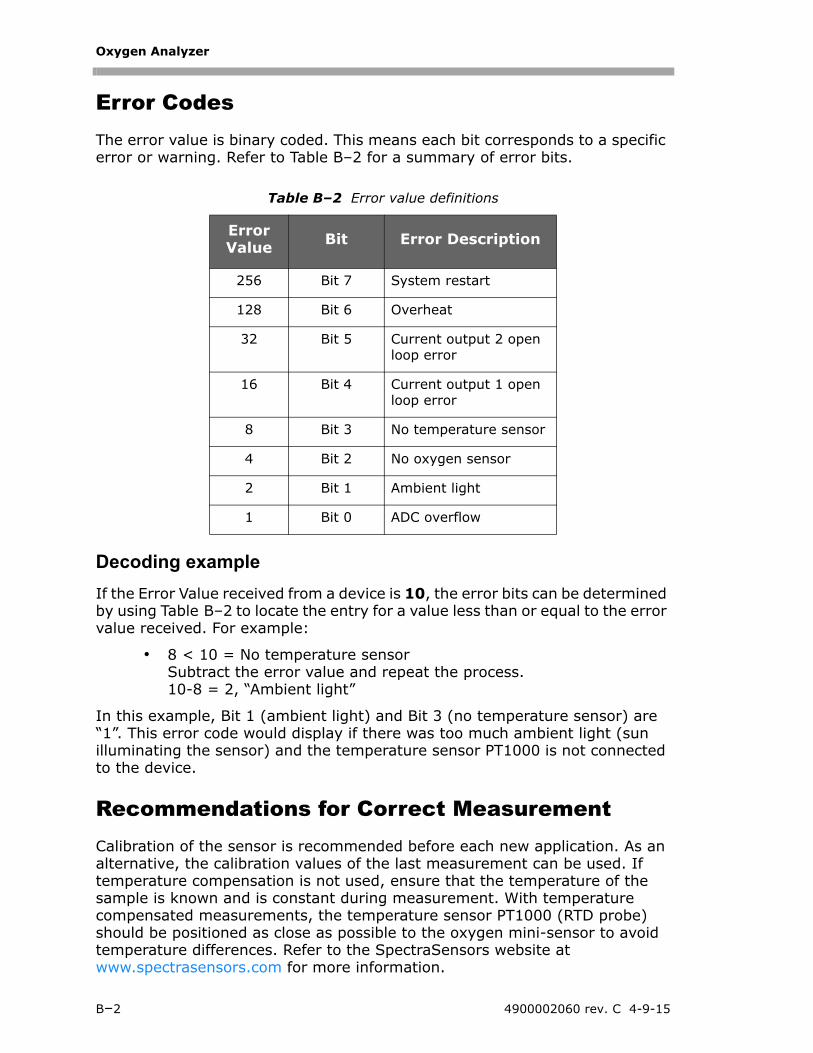
Oxygen Analyzer
Error CodesThe error value is binary coded. This means each bit corresponds to a specific error or warning. Refer to Table B–2 for a summary of error bits.
Decoding example
If the Error Value received from a device is 10, the error bits can be determined by using Table B–2 to locate the entry for a value less than or equal to the error value received. For example:
• 8 < 10 = No temperature sensorSubtract the error value and repeat the process.10-8 = 2, “Ambient light”
In this example, Bit 1 (ambient light) and Bit 3 (no temperature sensor) are “1”. This error code would display if there was too much ambient light (sun illuminating the sensor) and the temperature sensor PT1000 is not connected to the device.
Recommendations for Correct MeasurementCalibration of the sensor is recommended before each new application. As an alternative, the calibration values of the last measurement can be used. If temperature compensation is not used, ensure that the temperature of the sample is known and is constant during measurement. With temperature compensated measurements, the temperature sensor PT1000 (RTD probe) should be positioned as close as possible to the oxygen mini-sensor to avoid temperature differences. Refer to the SpectraSensors website at www.spectrasensors.com for more information.
Table B–2 Error value definitions
Error Value Bit Error Description
256 Bit 7 System restart
128 Bit 6 Overheat
32 Bit 5 Current output 2 open loop error
16 Bit 4 Current output 1 open loop error
8 Bit 3 No temperature sensor
4 Bit 2 No oxygen sensor
2 Bit 1 Ambient light
1 Bit 0 ADC overflow
B–2 4900002060 rev. C 4-9-15
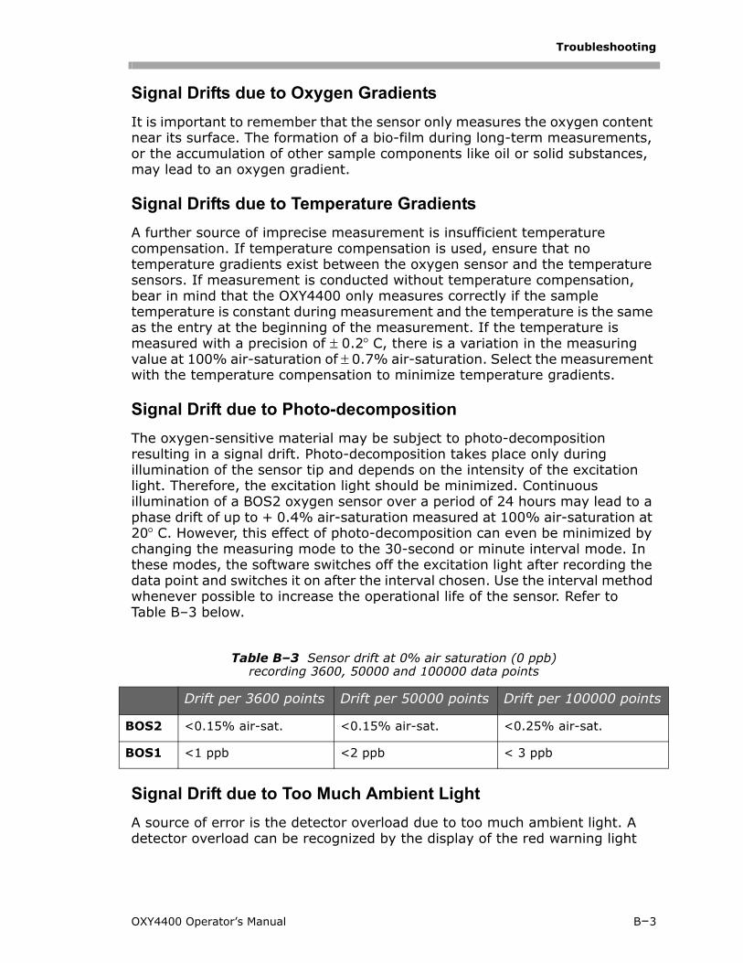
Troubleshooting
Signal Drifts due to Oxygen Gradients
It is important to remember that the sensor only measures the oxygen content near its surface. The formation of a bio-film during long-term measurements, or the accumulation of other sample components like oil or solid substances, may lead to an oxygen gradient.
Signal Drifts due to Temperature Gradients
A further source of imprecise measurement is insufficient temperature compensation. If temperature compensation is used, ensure that no temperature gradients exist between the oxygen sensor and the temperature sensors. If measurement is conducted without temperature compensation, bear in mind that the OXY4400 only measures correctly if the sample temperature is constant during measurement and the temperature is the same as the entry at the beginning of the measurement. If the temperature is measured with a precision of 0.2C, there is a variation in the measuring value at 100% air-saturation of 0.7% air-saturation. Select the measurement with the temperature compensation to minimize temperature gradients.
Signal Drift due to Photo-decomposition
The oxygen-sensitive material may be subject to photo-decomposition resulting in a signal drift. Photo-decomposition takes place only during illumination of the sensor tip and depends on the intensity of the excitation light. Therefore, the excitation light should be minimized. Continuous illumination of a BOS2 oxygen sensor over a period of 24 hours may lead to a phase drift of up to + 0.4% air-saturation measured at 100% air-saturation at 20C. However, this effect of photo-decomposition can even be minimized by changing the measuring mode to the 30-second or minute interval mode. In these modes, the software switches off the excitation light after recording the data point and switches it on after the interval chosen. Use the interval method whenever possible to increase the operational life of the sensor. Refer to Table B–3 below.
Signal Drift due to Too Much Ambient Light
A source of error is the detector overload due to too much ambient light. A detector overload can be recognized by the display of the red warning light
Table B–3 Sensor drift at 0% air saturation (0 ppb) recording 3600, 50000 and 100000 data points
Drift per 3600 points Drift per 50000 points Drift per 100000 points
BOS2 <0.15% air-sat. <0.15% air-sat. <0.25% air-sat.
BOS1 <1 ppb <2 ppb < 3 ppb
OXY4400 Operator’s Manual B–3
Oxygen Analyzer
“Overload” that can be found on the Main window of the PC program. Refer to See “Warning Lights” on page 5-13.
The sensor should be shielded from ambient light to obtain reliable data. A black overcoat, called optical isolation, is strongly recommended to reduce ambient light.
Oxygen Conversion FormulaThese conversion formulas are only valid in aqueous solutions and humidified air. These formulas have to be modified if measurements have to be performed in organic solvents or solutions with high salinity.
% O2 = % air - saturation •
0.2095: volume content of oxygen in air
ppm in gaseous phase:
ppm[O2] = % air-saturation • • =
1ppm = = = = %
Sensor SafetyThe oxygen-sensitive membrane can withstand gamma-sterilization, sterilization by etheylene oxide, steam autoclaving (140 C, 1.5 atm), CIP conditions (cleaning-in-place, 5% NaOH, 90 C), as well as 3% H2O2 (Hydrogen Peroxide) solution, if this is required for inline cleaning.
Performance ImprovementTo improve the performance over past measurements, check the calibration values by using the calibration test gases for “0” (UHP Nitrogen 99.9999%) and the Span test gas (100 ppm oxygen/N2). This can be completed by using a 3-way valve connected to the test gas enabling the user to switch back and forth between bottles. This can assist in verifying proper operation.
The measurement will not be reliable if the “Overload” warning light displays red. A detector overload causes a decrease in both amplitude and phase angle.
20.95100
-------------
20.95100
------------- 110000---------------
10000---------------% O2
11000000--------------------- 1mg
1kg----------- 1L
1L---------- 1
10000---------------
B–4 4900002060 rev. C 4-9-15
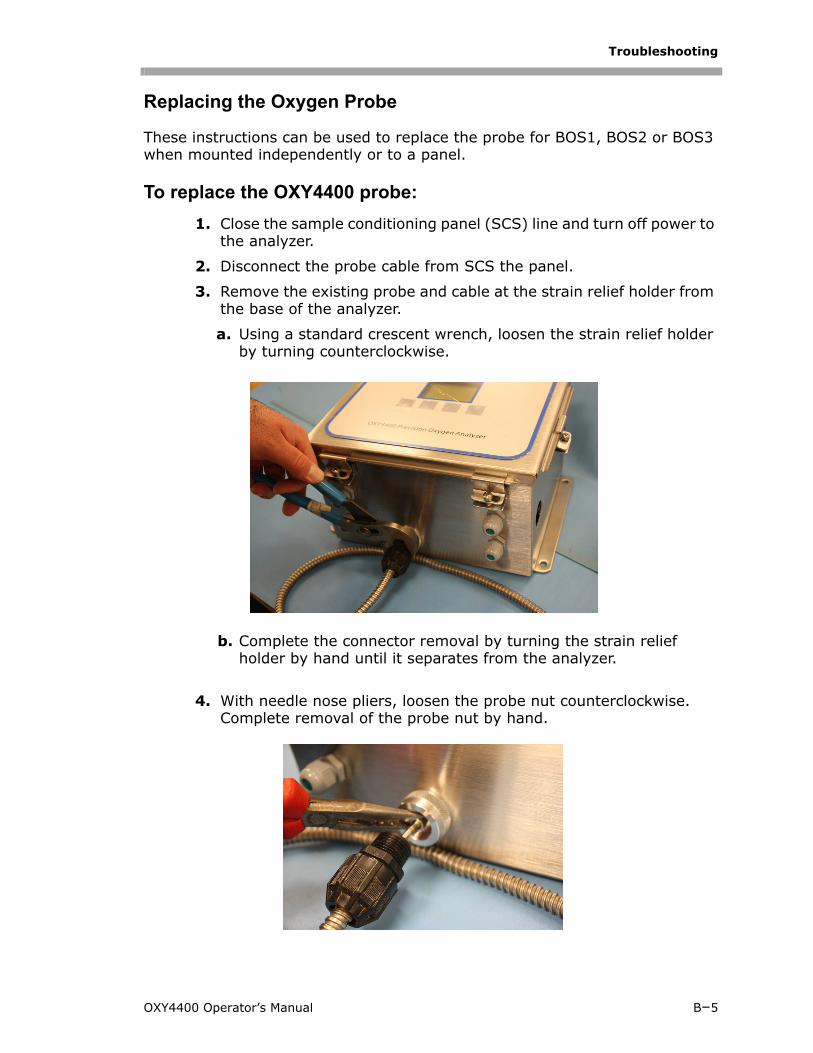
Troubleshooting
Replacing the Oxygen Probe
These instructions can be used to replace the probe for BOS1, BOS2 or BOS3 when mounted independently or to a panel.
To replace the OXY4400 probe:
1. Close the sample conditioning panel (SCS) line and turn off power to the analyzer.
2. Disconnect the probe cable from SCS the panel.
3. Remove the existing probe and cable at the strain relief holder from the base of the analyzer.
a. Using a standard crescent wrench, loosen the strain relief holder by turning counterclockwise.
b. Complete the connector removal by turning the strain relief holder by hand until it separates from the analyzer.
4. With needle nose pliers, loosen the probe nut counterclockwise. Complete removal of the probe nut by hand.
OXY4400 Operator’s Manual B–5
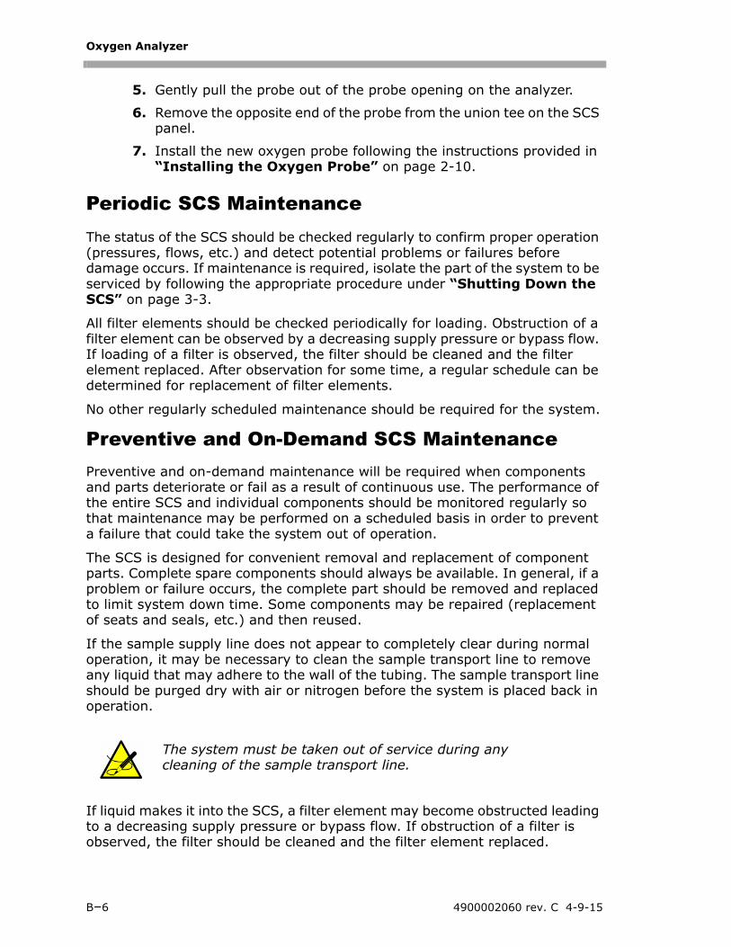
Oxygen Analyzer
5. Gently pull the probe out of the probe opening on the analyzer.
6. Remove the opposite end of the probe from the union tee on the SCS panel.
7. Install the new oxygen probe following the instructions provided in “Installing the Oxygen Probe” on page 2-10.
Periodic SCS MaintenanceThe status of the SCS should be checked regularly to confirm proper operation (pressures, flows, etc.) and detect potential problems or failures before damage occurs. If maintenance is required, isolate the part of the system to be serviced by following the appropriate procedure under “Shutting Down the SCS” on page 3-3.
All filter elements should be checked periodically for loading. Obstruction of a filter element can be observed by a decreasing supply pressure or bypass flow. If loading of a filter is observed, the filter should be cleaned and the filter element replaced. After observation for some time, a regular schedule can be determined for replacement of filter elements.
No other regularly scheduled maintenance should be required for the system.
Preventive and On-Demand SCS MaintenancePreventive and on-demand maintenance will be required when components and parts deteriorate or fail as a result of continuous use. The performance of the entire SCS and individual components should be monitored regularly so that maintenance may be performed on a scheduled basis in order to prevent a failure that could take the system out of operation.
The SCS is designed for convenient removal and replacement of component parts. Complete spare components should always be available. In general, if a problem or failure occurs, the complete part should be removed and replaced to limit system down time. Some components may be repaired (replacement of seats and seals, etc.) and then reused.
If the sample supply line does not appear to completely clear during normal operation, it may be necessary to clean the sample transport line to remove any liquid that may adhere to the wall of the tubing. The sample transport line should be purged dry with air or nitrogen before the system is placed back in operation.
If liquid makes it into the SCS, a filter element may become obstructed leading to a decreasing supply pressure or bypass flow. If obstruction of a filter is observed, the filter should be cleaned and the filter element replaced.
The system must be taken out of service during any cleaning of the sample transport line.
B–6 4900002060 rev. C 4-9-15
Troubleshooting
Regular SCS Status Check
1. Open the enclosure door, if analyzer is mounted in an enclosure.
2. Read and record the flowmeter settings while the gas is flowing.
3. Close the enclosure door, if applicable.
4. Compare the current readings with the past readings to determine any variations. Reading levels should remain consistent.
5. If reading levels decrease, check the filters.
To check filters:
1. Shut down the system following the procedure in “Shutting Down the SCS” on page 3-3.
2. Inspect, repair or replace the filter as required.
3. Restart the system following the procedure in “Starting up the SCS” on page 3-2.
Service ContactIf the troubleshooting solutions do not resolve the problem, contact customer service. To return the unit for service or replacement, refer to "Return Material Authorization".
Customer Service
4333 W Sam Houston Pkwy N, Suite 100Houston, TX 77043-1223United States of America
For SpectraSensors North America Service:
Phone: 1-800-619-2861, and press 2 for ServiceFax: 1-713-856-6623 E-mail: [email protected]
If your SCS is contained within a heated cabinet, do not leave the door open any longer than absolutely necessary. SpectraSensors recommends no more than 60 seconds. Opening the door may affect the temperature reading until the temperature is stabilized.
For additional information, contact SpectraSensors’ Technical Service Group at 800-619-2861.
OXY4400 Operator’s Manual B–7
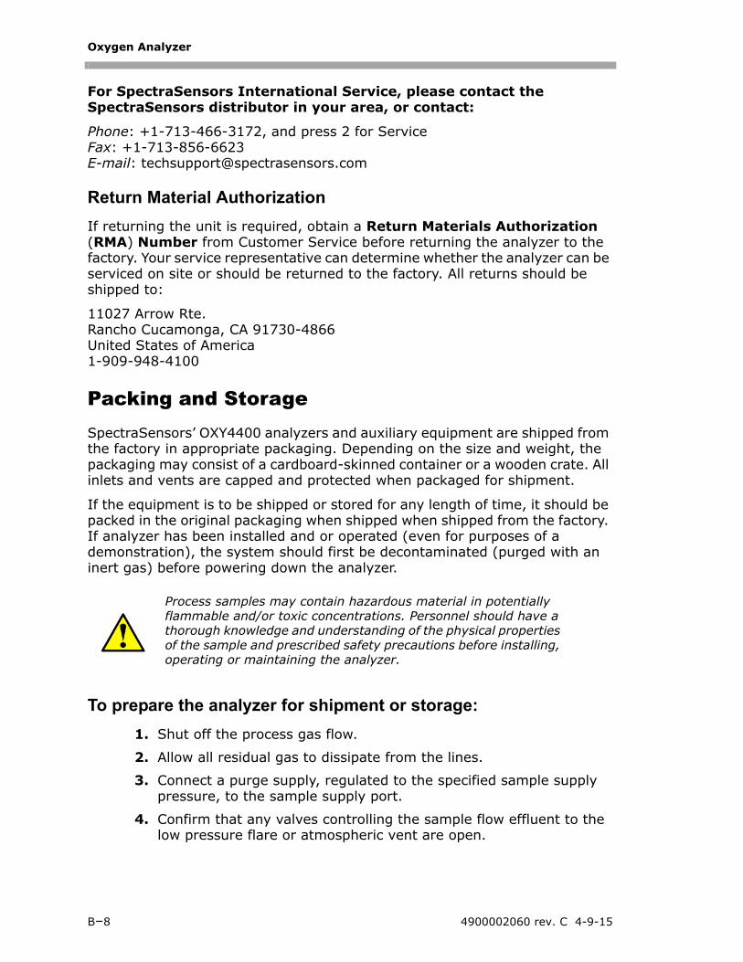
Oxygen Analyzer
For SpectraSensors International Service, please contact the SpectraSensors distributor in your area, or contact:
Phone: +1-713-466-3172, and press 2 for ServiceFax: +1-713-856-6623 E-mail: [email protected]
Return Material Authorization
If returning the unit is required, obtain a Return Materials Authorization (RMA) Number from Customer Service before returning the analyzer to the factory. Your service representative can determine whether the analyzer can be serviced on site or should be returned to the factory. All returns should be shipped to:
11027 Arrow Rte.Rancho Cucamonga, CA 91730-4866United States of America1-909-948-4100
Packing and StorageSpectraSensors’ OXY4400 analyzers and auxiliary equipment are shipped from the factory in appropriate packaging. Depending on the size and weight, the packaging may consist of a cardboard-skinned container or a wooden crate. All inlets and vents are capped and protected when packaged for shipment.
If the equipment is to be shipped or stored for any length of time, it should be packed in the original packaging when shipped when shipped from the factory. If analyzer has been installed and or operated (even for purposes of a demonstration), the system should first be decontaminated (purged with an inert gas) before powering down the analyzer.
To prepare the analyzer for shipment or storage:
1. Shut off the process gas flow.
2. Allow all residual gas to dissipate from the lines.
3. Connect a purge supply, regulated to the specified sample supply pressure, to the sample supply port.
4. Confirm that any valves controlling the sample flow effluent to the low pressure flare or atmospheric vent are open.
Process samples may contain hazardous material in potentially flammable and/or toxic concentrations. Personnel should have a thorough knowledge and understanding of the physical properties of the sample and prescribed safety precautions before installing, operating or maintaining the analyzer.
B–8 4900002060 rev. C 4-9-15
Troubleshooting
5. Turn on the purge supply and purge the system to clear any residual process gases.
6. Turn off the purge supply.
7. Allow all residual gas to dissipate from the lines.
8. Close any valves controlling the sample flow effluent to the low pressure flare or atmospheric vent.
9. Disconnect power to the system.
10. Disconnect all tubing and signal connections.
11. Cap all inlets and outlets to prevent foreign material such as dust or water from entering the system).
12. Pack the equipment in the original packaging in which it was shipped, if available. If the original packaging material is no longer available, the equipment should be adequately secured (to prevent excessive shock or vibration).
13. If returning the analyzer to the factory, complete the Decontamination Form provided by SpectraSensors "Customer Service" and attach to the outside of the shipping package as instructed before shipping.
Storage
The packaged analyzer should be stored in a sheltered environment that is temperature controlled between -20C (-4F) and 50C (122F), and should not be exposed to direct sun, rain, snow, condensing humidity or corrosive environments.
DisclaimersSpectraSensors accepts no responsibility for consequential damages arising from the use of this equipment. Liability is limited to replacement and/or repair of defective components.
This manual contains information protected by copyright. No part of this guide may be photocopied or reproduced in any form without prior written consent from SpectraSensors.
OXY4400 Operator’s Manual B–9

Oxygen Analyzer
THIS PAGE INTENTIONALLY LEFT BLANK
B–10 4900002060 rev. C 4-9-15
INDEX
Numerics4-20 mA current loop 2–6
AAnalyzer overview 1–2
BBasic equipment requirements 1–7
CCalibration
TemperatureManual 4–15Off 4–14On 4–11
Cautions 1–1Conditioning the analyzer tubing 2–14Connecting the optional automatic
validation 2–14Connecting the sample return line 2–8Connecting the sample supply line 2–8Current loop 2–6, 2–7
DDC systems 2–4Diagrams and schematics A–4, A–5, A–6
EEnclosure
Electronics 2–4, 2–7Heated 2–5Heater 2–4, 2–5
Erroneous readings 2–14Error codes B–2
FField pressure reducing regulator 3–1Field pressure reducing station 3–2Flowmeter 3–1, 3–3, 3–4
Sample 3–2
GGas leaks 2–9Gas lines
Connection 2–7Sample supply line 2–8
Graphical window displayStatus 5–14Zoom 5–14
Ground wire 2–4, 2–6
HHardware 2–2Heated enclosure 2–4, 2–5, 2–6
IInstallation
Hardware 2–1Software 5–1
LLeak detector 2–9
MMating terminal block 2–6, 2–7Measurement
Sampling Rate 4–6System 4–6Temperature 4–6, 4–8, 4–9
Measurement recommendations B–2Membrane separator 3–1Menu
Main 4–2Calibration 4–9
Calibrate 4–10Status 4–10
Configuration 4–18Analog In 4–20Analog Out 4–18Clock/Date 4–21Display 4–21Reset Config 4–21Status 4–18
Data logging 4–17Diag & Test 4–21
OXY4400 Operator’s Manual Index–1
Oxygen Analyzer
Inputs 4–22Outputs 4–22System 4–22
OOptional analyzer hood 2–3Output Signal
4-20 mA current loop 2–6Serial output 2–6
PPC Operation
Control Bar 5–5LED intensity 5–10
Advanced 5–11Auto adjust 5–10
Menu bar 5–3Menu Bar Definitions 5–4Oxygen unit adjustment 5–12
PC OperationsAnalog Input 5–9Analog Output 5–8Calibration Assistant 5–7Control Buttons 5–5Data Logging 5–7Instrument Info 5–8Measurement Assistant 5–6
Pin numbers 2–7Port
Bypass/sample return 2–8Sample supply 3–1
Power connections 4–1Power terminal box 2–5Pre-calibration 4–3Pressure regulator 3–1, 3–3
RReturn materials authorization (RMA)
number B–8
SSafety 1–5Sample bypass 3–2, 3–4
Start-up 3–2Sample conditioning system (SCS)
Periodic maintenance B–6Preventative and demand
maintenance B–6Shut down 3–3
Start-up 3–2Sample gas 3–1Sample probe 3–1, 3–2, 3–3Sensor Constants 4–5Sensor safety B–4Sensor Type 4–3Serial cable 2–7Serial connection 2–6Service contact B–8Signal drift B–3Stainless steel tubing 2–7System conditioning 2–14
TTechnical notes A–2Tools 2–2
VValve
Control 3–3Flowmeter control 3–3Isolation 3–1, 3–2, 3–3Metering 3–1, 3–3Relief 3–2Shut-off 3–1, 3–2, 3–4
WWarning lights 5–13, B–3Warnings
General 1–1
Index–2 4900002060 rev. C 4-9-15