Embed Size (px)
Citation preview

7/30/2019 Oxy Acetylene Welding and Cutting
http://slidepdf.com/reader/full/oxy-acetylene-welding-and-cutting 1/106
7/30/2019 Oxy Acetylene Welding and Cutting
http://slidepdf.com/reader/full/oxy-acetylene-welding-and-cutting 2/106
Oxy-Acetylene Welding and Cutting
Harold P. Manly Page 2
Oxy-Acetylene Welding and Cutting
Electric, Forge and Thermit Welding
Together with Related Methods and Materials Used in Metal Working And The
Oxygen Process for Removal of Carbon
By
HAROLD P. MANLY
7/30/2019 Oxy Acetylene Welding and Cutting
http://slidepdf.com/reader/full/oxy-acetylene-welding-and-cutting 3/106
Oxy-Acetylene Welding and Cutting
Harold P. Manly Page 3
PREFACE
In the preparation of this work, the object has been to cover not only the several processes of welding, but also those other processes which are so closely allied in method and results as to make them a partof the whole subject of joining metal to metal with the aid of heat.
The workman who wishes to handle his trade from start to finish finds that it is necessary to becomefamiliar with certain other operations which precede or follow the actual joining of the metal parts, the purpose of these operations being to add or retain certain desirable qualities in the materials beinghandled. For this reason the following subjects have been included: Annealing, tempering, hardening,heat treatment and the restoration of steel.
In order that the user may understand the underlying principles and the materials employed in this work,much practical information is given on the uses and characteristics of the various metals; on the production, handling and use of the gases and other materials which are a part of the equipment; and onthe tools and accessories for the production and handling of these materials.
An examination will show that the greatest usefulness of this book lies in the fact that all necessaryinformation and data has been included in one volume, making it possible for the workman to use onesource for securing a knowledge of both principle and practice, preparation and finishing of the work,and both large and small repair work as well as manufacturing methods used in metal working.
An effort has been made to eliminate all matter which is not of direct usefulness in practical work, whileincluding all that those engaged in this trade find necessary. To this end, the descriptions have beenlimited to those methods and accessories which are found in actual use today. For the same reason, thework includes the application of the rules laid down by the insurance underwriters which govern thiswork as well as instructions for the proper care and handling of the generators, torches and materialsfound in the shop.
Special attention has been given to definite directions for handling the different metals and alloys whichmust be handled. The instructions have been arranged to form rules which are placed in the order of their use during the work described and the work has been subdivided in such a way that it will be found possible to secure information on any one point desired without the necessity of spending time in other fields.
The facts which the expert welder and metalworker finds it most necessary to have readily availablehave been secured, and prepared especially for this work, and those of most general use have been
combined with the chapter on welding practice to which they apply.
The size of this volume has been kept as small as possible, but an examination of the alphabetical indexwill show that the range of subjects and details covered is complete in all respects. This has beenaccomplished through careful classification of the contents and the elimination of all repetition and alltheoretical, historical and similar matter that is not absolutely necessary.
7/30/2019 Oxy Acetylene Welding and Cutting
http://slidepdf.com/reader/full/oxy-acetylene-welding-and-cutting 4/106
Oxy-Acetylene Welding and Cutting
Harold P. Manly Page 4
Free use has been made of the information given by those manufacturers who are recognized as theleaders in their respective fields, thus insuring that the work is thoroughly practical and that it represents present day methods and practice.
THE AUTHOR.

7/30/2019 Oxy Acetylene Welding and Cutting
http://slidepdf.com/reader/full/oxy-acetylene-welding-and-cutting 5/106
Oxy-Acetylene Welding and Cutting
Harold P. Manly Page 5
CONTENTS
CHAPTER I
METALS AND ALLOYS--HEAT TREATMENT:--The Use and Characteristics of the IndustrialAlloys and Metal Elements--Annealing, Hardening, Tempering and Case Hardening of Steel
CHAPTER II
WELDING MATERIALS:--Production, Handling and Use of the Gases, Oxygen and Acetylene--Welding Rods--Fluxes--Supplies and Fixtures
CHAPTER III
ACETYLENE GENERATORS:--Generator Requirements and Types--Construction--Care and
Operation of Generators.
CHAPTER IV
WELDING INSTRUMENTS:--Tank and Regulating Valves and Gauges--High, Low and MediumPressure Torches--Cutting Torches--Acetylene-Air Torches
CHAPTER V
OXY-ACETYLENE WELDING PRACTICE:--Preparation of Work--Torch Practice-- Control of theFlame--Welding Various Metals and Alloys--Tables of Information Required in Welding Operations
CHAPTER VI
ELECTRIC WELDING:--Resistance Method--Butt, Spot and Lap Welding--Troubles and Remedies--Electric Arc Welding
CHAPTER VII
HAND FORGING AND WELDING:--Blacksmithing, Forging and Bending--Forge Welding Methods
CHAPTER VIII
SOLDERING, BRAZING AND THERMIT WELDING:--Soldering Materials and Practice-- Brazing--Thermit Welding
CHAPTER IX
OXYGEN PROCESS FOR REMOVAL OF CARBON
7/30/2019 Oxy Acetylene Welding and Cutting
http://slidepdf.com/reader/full/oxy-acetylene-welding-and-cutting 6/106
Oxy-Acetylene Welding and Cutting
Harold P. Manly Page 6
7/30/2019 Oxy Acetylene Welding and Cutting
http://slidepdf.com/reader/full/oxy-acetylene-welding-and-cutting 7/106
Oxy-Acetylene Welding and Cutting
Harold P. Manly Page 7
CHAPTER I
METALS AND THEIR ALLOYS--HEAT TREATMENT
THE METALS
Iron.--Iron, in its pure state, is a soft, white, easily worked metal. It is the most important of all themetallic elements, and is, next to aluminum, the commonest metal found in the earth.
Mechanically speaking, we have three kinds of iron: wrought iron, cast iron and steel. Wrought iron isvery nearly pure iron; cast iron contains carbon and silicon, also chemical impurities; and steel containsa definite proportion of carbon, but in smaller quantities than cast iron.
Pure iron is never obtained commercially, the metal always being mixed with various proportions of
carbon, silicon, sulphur, phosphorus, and other elements, making it more or less suitable for different purposes. Iron is magnetic to the extent that it is attracted by magnets, but it does not retain magnetismitself, as does steel. Iron forms, with other elements, many important combinations, such as its alloys,oxides, and sulphates.
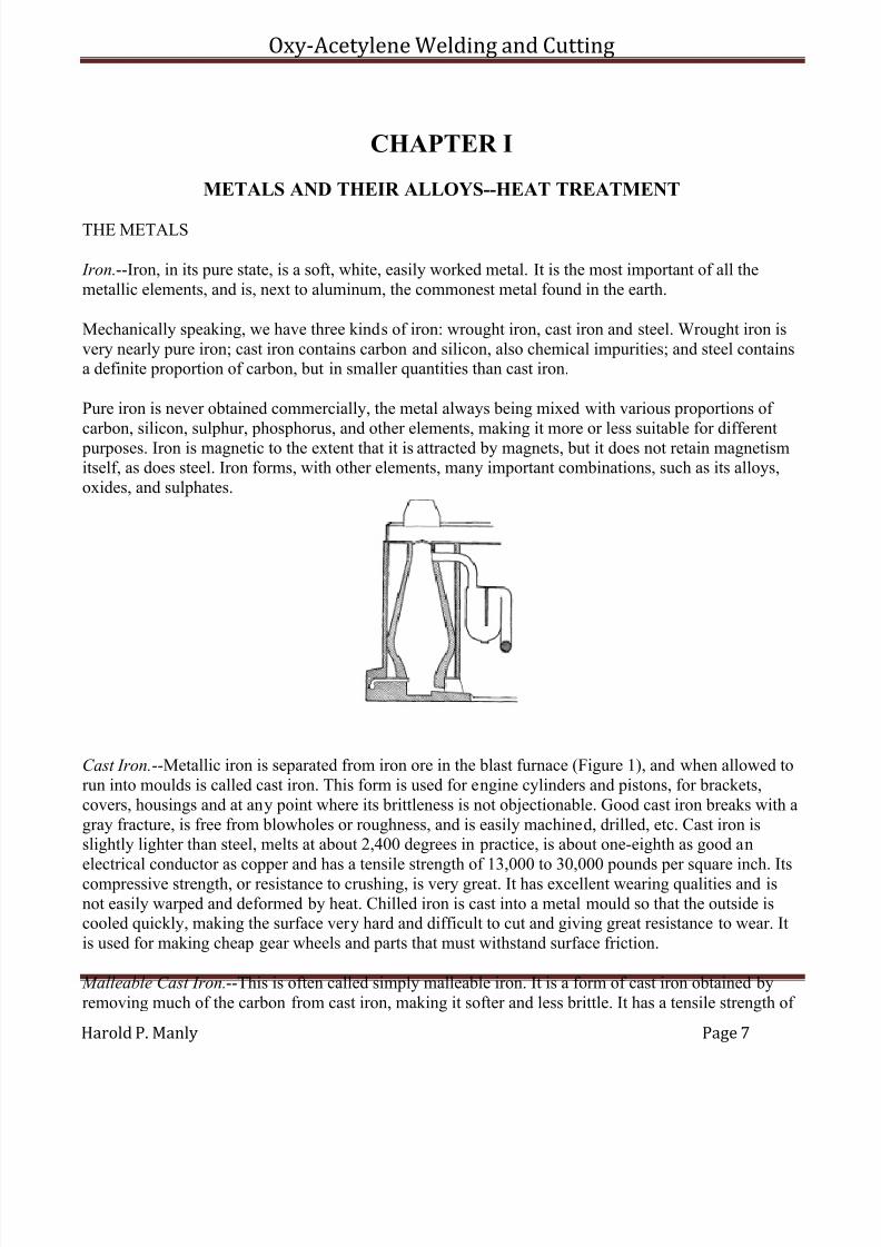
Cast Iron.--Metallic iron is separated from iron ore in the blast furnace (Figure 1), and when allowed torun into moulds is called cast iron. This form is used for engine cylinders and pistons, for brackets,covers, housings and at any point where its brittleness is not objectionable. Good cast iron breaks with agray fracture, is free from blowholes or roughness, and is easily machined, drilled, etc. Cast iron isslightly lighter than steel, melts at about 2,400 degrees in practice, is about one-eighth as good anelectrical conductor as copper and has a tensile strength of 13,000 to 30,000 pounds per square inch. Itscompressive strength, or resistance to crushing, is very great. It has excellent wearing qualities and isnot easily warped and deformed by heat. Chilled iron is cast into a metal mould so that the outside iscooled quickly, making the surface very hard and difficult to cut and giving great resistance to wear. Itis used for making cheap gear wheels and parts that must withstand surface friction.
Malleable Cast Iron.--This is often called simply malleable iron. It is a form of cast iron obtained byremoving much of the carbon from cast iron, making it softer and less brittle. It has a tensile strength of
7/30/2019 Oxy Acetylene Welding and Cutting
http://slidepdf.com/reader/full/oxy-acetylene-welding-and-cutting 8/106
Oxy-Acetylene Welding and Cutting
Harold P. Manly Page 8
25,000 to 45,000 pounds per square inch, is easily machined, will stand a small amount of bending at alow red heat and is used chiefly in making brackets, fittings and supports where low cost is of considerable importance. It is often used in cheap constructions in place of steel forgings. The greateststrength of a malleable casting, like a steel forging, is in the surface, therefore but little machining
should be done.
Wrought Iron.--This grade is made by treating the cast iron to remove almost all of the carbon, silicon, phosphorus, sulphur, manganese and other impurities. This process leaves a small amount of the slagfrom the ore mixed with the wrought iron.
Wrought iron is used for making bars to be machined into various parts. If drawn through the rolls at themill once, while being made, it is called "muck bar;" if rolled twice, it is called "merchant bar" (thecommonest kind), and a still better grade is made by rolling a third time. Wrought iron is beinggradually replaced in use by mild rolled steels. Wrought iron is slightly heavier than cast iron, is a much better electrical conductor than either cast iron or steel, has a tensile strength of 40,000 to 60,000
pounds per square inch and costs slightly more than steel. Unlike either steel or cast iron, wrought irondoes not harden when cooled suddenly from a red heat.
Grades of Irons.--The mechanical properties of cast iron differ greatly according to the amount of other materials it contains. The most important of these contained elements is carbon, which is present to adegree varying from 2 to 5-1/2 per cent. When iron containing much carbon is quickly cooled and then broken, the fracture is nearly white in color and the metal is found to be hard and brittle. When the ironis slowly cooled and then broken the fracture is gray and the iron is more malleable and less brittle. If cast iron contains sulphur or phosphorus, it will show a white fracture regardless of the rapidity of cooling, being brittle and less desirable for general work.
Steel.--Steel is composed of extremely minute particles of iron and carbon, forming a network of layersand bands. This carbon is a smaller proportion of the metal than found in cast iron, the percentage beingfrom 3/10 to 2-1/2 per cent.
Carbon steel is specified according to the number of "points" of carbon, a point being one one-hundredth of one per cent of the weight of the steel. Steel may contain anywhere from 30 to 250 points,which is equivalent to saying, anywhere from 3/10 to 2-1/2 per cent, as above. A 70-point steel wouldcontain 70/100 of one per cent or 7/10 of one per cent of carbon by weight. The percentage of carbondetermines the hardness of the steel, also many other qualities, and its suitability for various kinds of work. The more carbon contained in the steel, the harder the metal will be, and, of course, its brittlenessincreases with the hardness. The smaller the grains or particles of iron which are separated by the
carbon, the stronger the steel will be, and the control of the size of these particles is the object of thescience of heat treatment.
In addition to the carbon, steel may contain the following:
Silicon, which increases the hardness, brittleness, strength and difficulty of working if from 2 to 3 per cent is present.
7/30/2019 Oxy Acetylene Welding and Cutting
http://slidepdf.com/reader/full/oxy-acetylene-welding-and-cutting 9/106
Oxy-Acetylene Welding and Cutting
Harold P. Manly Page 9
Phosphorus, which hardens and weakens the metal but makes it easier to cast. Three-tenths per cent of phosphorus serves as a hardening agent and may be present in good steel if the percentage of carbon islow. More than this weakens the metal.
Sulphur, which tends to make the metal hard and filled with small holes.
Manganese, which makes the steel so hard and tough that it can with difficulty be cut with steel tools.Its hardness is not lessened by annealing, and it has great tensile strength.
Alloy steel has a varying but small percentage of other elements mixed with it to give certain desiredqualities. Silicon steel and manganese steel are sometimes classed as alloy steels. This subject is takenup in the latter part of this chapter under Alloys, where the various combinations and their characteristicsare given consideration.
Steel has a tensile strength varying from 50,000 to 300,000 pounds per square inch, depending on the
carbon percentage and the other alloys present, as well as upon the texture of the grain. Steel is heavier than cast iron and weighs about the same as wrought iron. It is about one-ninth as good a conductor of electricity as copper.
Steel is made from cast iron by three principal processes: the crucible, Bessemer and open hearth.
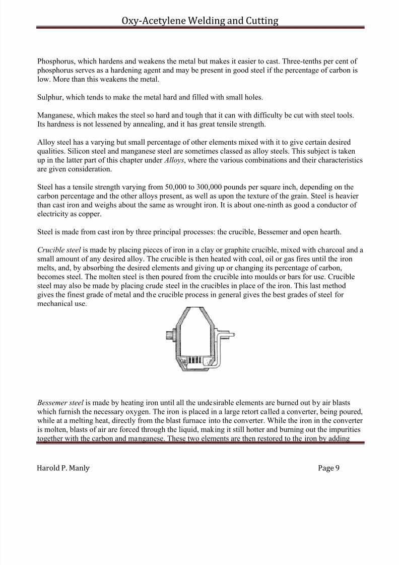
Crucible steel is made by placing pieces of iron in a clay or graphite crucible, mixed with charcoal and asmall amount of any desired alloy. The crucible is then heated with coal, oil or gas fires until the ironmelts, and, by absorbing the desired elements and giving up or changing its percentage of carbon, becomes steel. The molten steel is then poured from the crucible into moulds or bars for use. Cruciblesteel may also be made by placing crude steel in the crucibles in place of the iron. This last method
gives the finest grade of metal and the crucible process in general gives the best grades of steel for mechanical use.
Bessemer steel is made by heating iron until all the undesirable elements are burned out by air blastswhich furnish the necessary oxygen. The iron is placed in a large retort called a converter, being poured,while at a melting heat, directly from the blast furnace into the converter. While the iron in the converter is molten, blasts of air are forced through the liquid, making it still hotter and burning out the impuritiestogether with the carbon and manganese. These two elements are then restored to the iron by adding

7/30/2019 Oxy Acetylene Welding and Cutting
http://slidepdf.com/reader/full/oxy-acetylene-welding-and-cutting 10/106
Oxy-Acetylene Welding and Cutting
Harold P. Manly Page 10
spiegeleisen (an alloy of iron, carbon and manganese). A converter holds from 5 to 25 tons of metal andrequires about 20 minutes to finish a charge. This makes the cheapest steel.
Open hearth steel is made by placing the molten iron in a receptacle while currents of air pass over it,this air having itself been highly heated by just passing over white hot brick (Figure. 3). Open hearthsteel is considered more uniform and reliable than Bessemer, and is used for springs, bar steel, toolsteel, steel plates, etc.
Aluminum is one of the commonest industrial metals. It is used for gear cases, engine crank cases,covers, fittings, and wherever lightness and moderate strength are desirable.
Aluminum is about one-third the weight of iron and about the same weight as glass and porcelain; it is agood electrical conductor (about one-half as good as copper); is fairly strong itself and gives greatstrength to other metals when alloyed with them. One of the greatest advantages of aluminum is that i twill not rust or corrode under ordinary conditions. The granular formation of aluminum makes itsstrength very unreliable and it is too soft to resist wear.
Copper is one of the most important metals used in the trades, and the best commercial conductor of electricity, being exceeded in this respect only by silver, which is but slightly better. Copper is very
malleable and ductile when cold, and in this state may be easily worked under the hammer. Working inthis way makes the copper stronger and harder, but less ductile. Copper is not affected by air, but acidscause the formation of a green deposit called verdigris.
Copper is one of the best conductors of heat, as well as electricity, being used for kettles, boilers, stillsand wherever this quality is desirable. Copper is also used in alloys with other metals, forming animportant part of brass, bronze, german silver, bell metal and gun metal. It is about one-eighth heavier than steel and has a tensile strength of about 25,000 to 50,000 pounds per square inch.
Lead.--The peculiar properties of lead, and especially its quality of showing but little action or chemicalchange in the presence of other elements, makes it valuable under certain conditions of use. Its principal
use is in pipes for water and gas, coverings for roofs and linings for vats and tanks. It is also used to coatsheet iron for similar uses and as an important part of ordinary solder.
Lead is the softest and weakest of all the commercial metals, being very pliable and inelastic. It should be remembered that lead and all its compounds are poisonous when received into the system. Lead ismore than one-third heavier than steel, has a tensile strength of only about 2,000 pounds per squareinch, and is only about one-tenth as good a conductor of electricity as copper.
7/30/2019 Oxy Acetylene Welding and Cutting
http://slidepdf.com/reader/full/oxy-acetylene-welding-and-cutting 11/106
Oxy-Acetylene Welding and Cutting
Harold P. Manly Page 11
Zinc.--This is a bluish-white metal of crystalline form. It is brittle at ordinary temperatures and becomesmalleable at about 250 to 300 degrees Fahrenheit, but beyond this point becomes even more brittle thanat ordinary temperatures. Zinc is practically unaffected by air or moisture through becoming coveredwith one of its own compounds which immediately resists further action. Zinc melts at low
temperatures, and when heated beyond the melting point gives off very poisonous fumes.
The principal use of zinc is as an alloy with other metals to form brass, bronze, german silver and bearing metals. It is also used to cover the surface of steel and iron plates, the plates being then calledgalvanized.
Zinc weighs slightly less than steel, has a tensile strength of 5,000 pounds per square inch, and is notquite half as good as copper in conducting electricity.
Tin resembles silver in color and luster. Tin is ductile and malleable and slightly crystalline in form,almost as heavy as steel, and has a tensile strength of 4,500 pounds per square inch.
The principal use of tin is for protective platings on household utensils and in wrappings of tin-foil. Tinforms an important part of many alloys such as babbitt, Britannia metal, bronze, gun metal and bearingmetals.
Nickel is important in mechanics because of its combinations with other metals as alloys. Pure nickel isgrayish-white, malleable, ductile and tenacious. It weighs almost as much as steel and, next tomanganese, is the hardest of metals. Nickel is one of the three magnetic metals, the others being ironand cobalt. The commonest alloy containing nickel is german silver, although one of its most importantalloys is found in nickel steel. Nickel is about ten per cent heavier than steel, and has a tensile strengthof 90,000 pounds per square inch.
Platinum.--This metal is valuable for two reasons: it is not affected by the air or moisture or anyordinary acid or salt, and in addition to this property it melts only at the highest temperatures. It is afairly good electrical conductor, being better than iron or steel. It is nearly three times as heavy as steeland its tensile strength is 25,000 pounds per square inch.
ALLOYS
An alloy is formed by the union of a metal with some other material, either metal or non-metallic, thisunion being composed of two or more elements and usually brought about by heating the substancestogether until they melt and unite. Metals are alloyed with materials which have been found to give to
the metal certain characteristics which are desired according to the use the metal will be put to.
The alloys of metals are, almost without exception, more important from an industrial standpoint thanthe metals themselves. There are innumerable possible combinations, the most useful of which are hereclassed under the head of the principal metal entering into their composition.

7/30/2019 Oxy Acetylene Welding and Cutting
http://slidepdf.com/reader/full/oxy-acetylene-welding-and-cutting 12/106
Oxy-Acetylene Welding and Cutting
Harold P. Manly Page 12
Steel.--Steel may be alloyed with almost any of the metals or elements, the combinations that have proven valuable numbering more than a score. The principal ones are given in alphabetical order, asfollows:
Aluminum is added to steel in very small amounts for the purpose of preventing blow holes in castings.
Boron increases the density and toughness of the metal.
Bronze, added by alloying copper, tin and iron, is used for gun metal.
Carbon has already been considered under the head of steel in the section devoted to the metals. Carbon,while increasing the strength and hardness, decreases the ease of forging and bending and decreases themagnetism and electrical conductivity. High carbon steel can be welded only with difficulty. When the percentage of carbon is low, the steel is called "low carbon" or "mild" steel. This is used for rods andshafts, and called "machine" steel. When the carbon percentage is high, the steel is called "high carbon"
steel, and it is used in the shop as tool steel. One-tenth per cent of carbon gives steel a tensile strength of 50,000 to 65,000 pounds per square inch; two-tenths per cent gives from 60,000 to 80,000; four-tenths per cent gives 70,000 to 100,000, and six-tenths per cent gives 90,000 to 120,000.
Chromium forms chrome steel, and with the further addition of nickel is called chrome nickel steel. Thisincreases the hardness to a high degree and adds strength without much decrease in ductility. Chromesteels are used for high-speed cutting tools, armor plate, files, springs, safes, dies, etc.
Manganese has been mentioned under Steel . Its alloy is much used for high-speed cutting tools, the steelhardening when cooled in the air and being called self-hardening.
Molybdenum is used to increase the hardness to a high degree and makes the steel suitable for high-speed cutting and gives it self-hardening properties.
Nickel, with which is often combined chromium, increases the strength, springiness and toughness andhelps to prevent corrosion.
Silicon has already been described. It suits the metal for use in high-speed tools.
Silver added to steel has many of the properties of nickel.
Tungsten increases the hardness without making the steel brittle. This makes the steel well suited for gas
engine valves as it resists corrosion and pitting. Chromium and manganese are often used incombination with tungsten when high-speed cutting tools are made.
Vanadium as an alloy increases the elastic limit, making the steel stronger, tougher and harder. It alsomakes the steel able to stand much bending and vibration.
Copper.--The principal copper alloys include brass, bronze, german silver and gun metal.
7/30/2019 Oxy Acetylene Welding and Cutting
http://slidepdf.com/reader/full/oxy-acetylene-welding-and-cutting 13/106
Oxy-Acetylene Welding and Cutting
Harold P. Manly Page 13
Brass is composed of approximately one-third zinc and two-thirds copper. It is used for bearings and bushings where the speeds are slow and the loads rather heavy for the bearing size. It also finds use inwashers, collars and forms of brackets where the metal should be non-magnetic, also for many highlyfinished parts.
Brass is about one-third as good an electrical conductor as copper, is slightly heavier than steel and hasa tensile strength of 15,000 pounds when cast and about 75,000 to 100,000 pounds when drawn intowire.
Bronze is composed of copper and tin in various proportions, according to the use to which it is to be put. There will always be from six-tenths to nine-tenths of copper in the mixture. Bronze is used for bearings, bushings, thrust washers, brackets and gear wheels. It is heavier than steel, about 1/15 as goodan electrical conductor as pure copper and has a tensile strength of 30,000 to 60,000 pounds.
Aluminum bronze, composed of copper, zinc and aluminum has high tensile strength combined with
ductility and is used for parts requiring this combination.
Bearing bronze is a variable material, its composition and proportion depending on the maker and theuse for which it is designed. It usually contains from 75 to 85 per cent of copper combined with one or more elements, such as tin, zinc, antimony and lead.
White metal is one form of bearing bronze containing over 80 per cent of zinc together with copper, tin,antimony and lead. Another form is made with nearly 90 per cent of tin combined with copper andantimony.
Gun metal bronze is made from 90 per cent copper with 10 per cent of tin and is used for heavy
bearings, brackets and highly finished parts.
Phosphor bronze is used for very strong castings and bearings. It is similar to gun metal bronze, exceptthat about 1-1/2 per cent of phosphorus has been added.
Manganese bronze contains about 1 per cent of manganese and is used for parts requiring great strengthwhile being free from corrosion.
German silver is made from 60 per cent of copper with 20 per cent each of zinc and nickel. Its highelectrical resistance makes it valuable for regulating devices and rheostats.
Tin is the principal part of babbitt and solder . A commonly used babbitt is composed of 89 per cent tin,8 per cent antimony and 3 per cent of copper. A grade suitable for repairing is made from 80 per cent of lead and 20 per cent antimony. This last formula should not be used for particular work or heavy loads, being more suitable for spacers. Innumerable proportions of metals are marketed under the name of babbitt.
7/30/2019 Oxy Acetylene Welding and Cutting
http://slidepdf.com/reader/full/oxy-acetylene-welding-and-cutting 14/106
Oxy-Acetylene Welding and Cutting
Harold P. Manly Page 14
Solder is made from 50 per cent tin and 50 per cent lead, this grade being called "half-and-half." Hardsolder is made from two-thirds tin and one-third lead.
Aluminum forms many different alloys, giving increased strength to whatever metal it unites with.
Aluminum brass is composed of approximately 65 per cent copper, 30 per cent zinc and 5 per centaluminum. It forms a metal with high tensile strength while being ductile and malleable.
Aluminum zinc is suitable for castings which must be stiff and hard.
Nickel aluminum has a tensile strength of 40,000 pounds per square inch.
Magnalium is a silver-white alloy of aluminum with from 5 to 20 per cent of magnesium, forming ametal even lighter than aluminum and strong enough to be used in making high-speed gasoline engines.
HEAT TREATMENT OF STEEL
The processes of heat treatment are designed to suit the steel for various purposes by changing the sizeof the grain in the metal, therefore the strength; and by altering the chemical composition of the alloysin the metal to give it different physical properties. Heat treatment, as applied in ordinary shop work,includes the three processes of annealing, hardening and tempering, each designed to accomplish acertain definite result.
All of these processes require that the metal treated be gradually brought to a certain predetermineddegree of heat which shall be uniform throughout the piece being handled and, from this point, cooledaccording to certain rules, the selection of which forms the difference in the three methods.
Annealing.--This is the process which relieves all internal strains and distortion in the metal and softensit so that it may more easily be cut, machined or bent to the required form. In some cases annealing isused only to relieve the strains, this being the case after forging or welding operations have been performed. In other cases it is only desired to soften the metal sufficiently that it may be handled easily.In some cases both of these things must be accomplished, as after a piece has been forged and must bemachined. No matter what the object, the procedure is the same.
The steel to be annealed must first be heated to a dull red. This heating should be done slowly so that all parts of the piece have time to reach the same temperature at very nearly the same time. The piece may be heated in the forge, but a much better way is to heat in an oven or furnace of some type where the
work is protected against air currents, either hot or cold, and is also protected against the direct action of the fire.

7/30/2019 Oxy Acetylene Welding and Cutting
http://slidepdf.com/reader/full/oxy-acetylene-welding-and-cutting 15/106
Oxy-Acetylene Welding and Cutting
Harold P. Manly Page 15
Probably the simplest of all ovens for small tools is made by placing a piece of ordinary gas pipe in thefire (Figure 4), and heating until the inside of the pipe is bright red. Parts placed in this pipe, after oneend has been closed, may be brought to the desired heat without danger of cooling draughts or chemicalchange from the action of the fire. More elaborate ovens may be bought which use gas, fuel oils or coalto produce the heat and in which the work may be placed on trays so that the fire will not strike directlyon the steel being treated.
If the work is not very important, it may be withdrawn from the fire or oven, after heating to the desired
point, and allowed to cool in the air until all traces of red have disappeared when held in a dark place.The work should be held where it is reasonably free from cold air currents. If, upon touching a pinestick to the piece being annealed, the wood does not smoke, the work may then be cooled in water.
Better annealing is secured and harder metal may be annealed if the cooling is extended over a number of hours by placing the work in a bed of non-heat-conducting material, such as ashes, charred bone,asbestos fibre, lime, sand or fire clay. It should be well covered with the heat retaining material andallowed to remain until cool. Cooling may be accomplished by allowing the fire in an oven or furnace todie down and go out, leaving the work inside the oven with all openings closed. The greater the timetaken for gradual cooling from the red heat, the more perfect will be the results of the annealing.
While steel is annealed by slow cooling, copper or brass is annealed by bringing to a low red heat andquickly plunging into cold water.
Hardening.--Steel is hardened by bringing to a proper temperature, slowly and evenly as for annealing,and then cooling more or less quickly, according to the grade of steel being handled. The degree of hardening is determined by the kind of steel, the temperature from which the metal is cooled and thetemperature and nature of the bath into which it is plunged for cooling.
Steel to be hardened is often heated in the fire until at some heat around 600 to 700 degrees is reached,then placed in a heating bath of molten lead, heated mercury, fused cyanate of potassium, etc., theheating bath itself being kept at the proper temperature by fires acting on it. While these baths have the
advantage of heating the metal evenly and to exactly the temperature desired throughout without any part becoming over or under heated, their disadvantages consist of the fact that their materials and thefumes are poisonous in most all cases, and if not poisonous, are extremely disagreeable.
The degree of heat that a piece of steel must be brought to in order that it may be hardened depends onthe percentage of carbon in the steel. The greater the percentage of carbon, the lower the heat necessaryto harden.
7/30/2019 Oxy Acetylene Welding and Cutting
http://slidepdf.com/reader/full/oxy-acetylene-welding-and-cutting 16/106
Oxy-Acetylene Welding and Cutting
Harold P. Manly Page 16
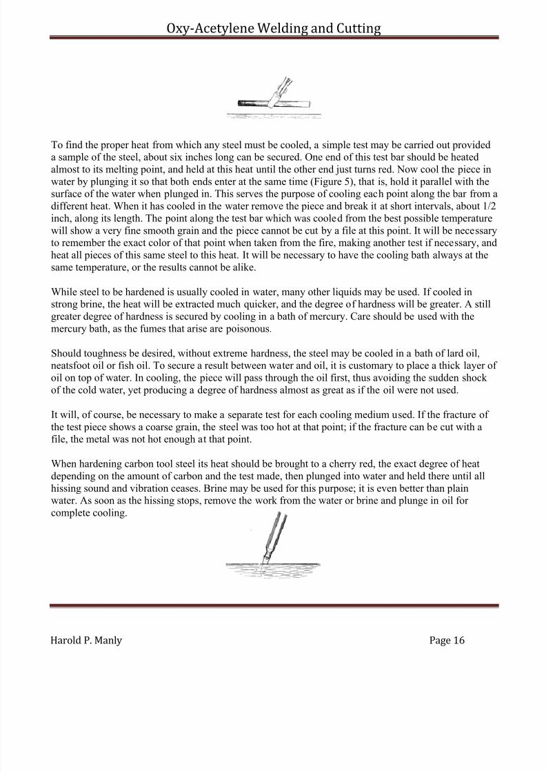
To find the proper heat from which any steel must be cooled, a simple test may be carried out provideda sample of the steel, about six inches long can be secured. One end of this test bar should be heatedalmost to its melting point, and held at this heat until the other end just turns red. Now cool the piece inwater by plunging it so that both ends enter at the same time (Figure 5), that is, hold it parallel with thesurface of the water when plunged in. This serves the purpose of cooling each point along the bar from adifferent heat. When it has cooled in the water remove the piece and break it at short intervals, about 1/2inch, along its length. The point along the test bar which was cooled from the best possible temperaturewill show a very fine smooth grain and the piece cannot be cut by a file at this point. It will be necessaryto remember the exact color of that point when taken from the fire, making another test if necessary, andheat all pieces of this same steel to this heat. It will be necessary to have the cooling bath always at the
same temperature, or the results cannot be alike.
While steel to be hardened is usually cooled in water, many other liquids may be used. If cooled instrong brine, the heat will be extracted much quicker, and the degree of hardness will be greater. A stillgreater degree of hardness is secured by cooling in a bath of mercury. Care should be used with themercury bath, as the fumes that arise are poisonous.
Should toughness be desired, without extreme hardness, the steel may be cooled in a bath of lard oil,neatsfoot oil or fish oil. To secure a result between water and oil, it is customary to place a thick layer of oil on top of water. In cooling, the piece will pass through the oil first, thus avoiding the sudden shock of the cold water, yet producing a degree of hardness almost as great as if the oil were not used.
It will, of course, be necessary to make a separate test for each cooling medium used. If the fracture of the test piece shows a coarse grain, the steel was too hot at that point; if the fracture can be cut with afile, the metal was not hot enough at that point.
When hardening carbon tool steel its heat should be brought to a cherry red, the exact degree of heatdepending on the amount of carbon and the test made, then plunged into water and held there until allhissing sound and vibration ceases. Brine may be used for this purpose; it is even better than plainwater. As soon as the hissing stops, remove the work from the water or brine and plunge in oil for complete cooling.
7/30/2019 Oxy Acetylene Welding and Cutting
http://slidepdf.com/reader/full/oxy-acetylene-welding-and-cutting 17/106
Oxy-Acetylene Welding and Cutting
Harold P. Manly Page 17
In hardening high-speed tool steel, or air hardening steels, the tool should be handled as for carbon steel,except that after the body reaches a cherry red, the cutting point must be quickly brought to a white heat,almost melting, so that it seems ready for welding. Then cool in an oil bath or in a current of cool air.
Hardening of copper, brass and bronze is accomplished by hammering or working them while cold.
Tempering is the process of making steel tough after it has been hardened, so that it will hold a cuttingedge and resist cracking. Tempering makes the grain finer and the metal stronger. It does not affect thehardness, but increases the elastic limit and reduces the brittleness of the steel. In that tempering isusually performed immediately after hardening, it might be considered as a continuation of the former process.
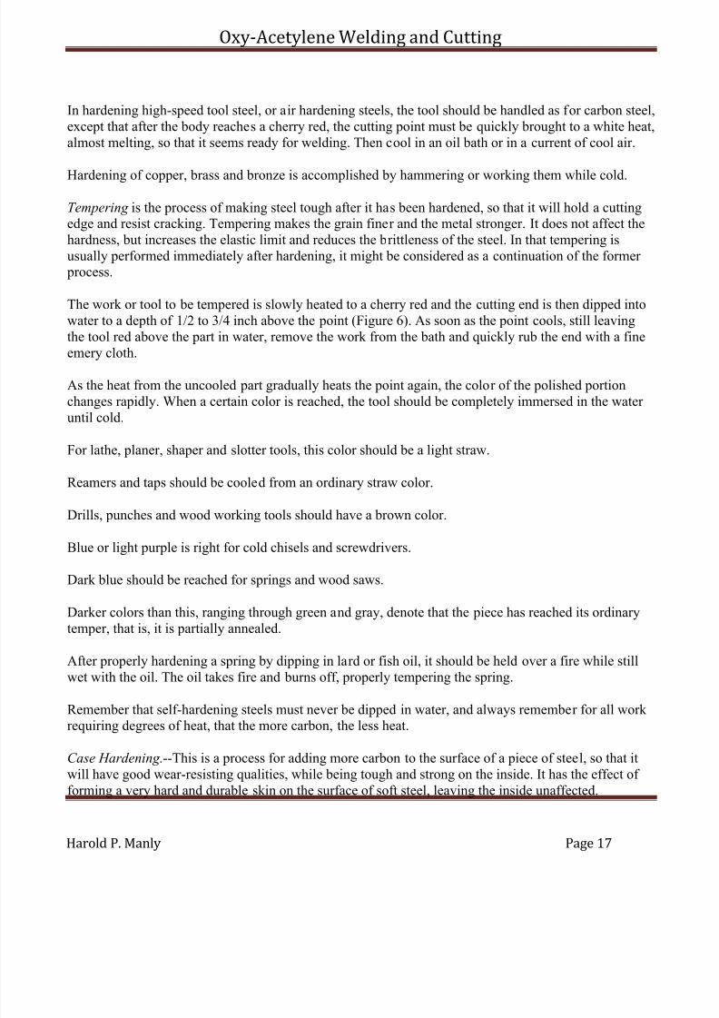
The work or tool to be tempered is slowly heated to a cherry red and the cutting end is then dipped intowater to a depth of 1/2 to 3/4 inch above the point (Figure 6). As soon as the point cools, still leavingthe tool red above the part in water, remove the work from the bath and quickly rub the end with a fine
emery cloth.
As the heat from the uncooled part gradually heats the point again, the color of the polished portionchanges rapidly. When a certain color is reached, the tool should be completely immersed in the water until cold.
For lathe, planer, shaper and slotter tools, this color should be a light straw.
Reamers and taps should be cooled from an ordinary straw color.
Drills, punches and wood working tools should have a brown color.
Blue or light purple is right for cold chisels and screwdrivers.
Dark blue should be reached for springs and wood saws.
Darker colors than this, ranging through green and gray, denote that the piece has reached its ordinarytemper, that is, it is partially annealed.
After properly hardening a spring by dipping in lard or fish oil, it should be held over a fire while stillwet with the oil. The oil takes fire and burns off, properly tempering the spring.
Remember that self-hardening steels must never be dipped in water, and always remember for all work requiring degrees of heat, that the more carbon, the less heat.
Case Hardening.--This is a process for adding more carbon to the surface of a piece of steel, so that itwill have good wear-resisting qualities, while being tough and strong on the inside. It has the effect of forming a very hard and durable skin on the surface of soft steel, leaving the inside unaffected.
7/30/2019 Oxy Acetylene Welding and Cutting
http://slidepdf.com/reader/full/oxy-acetylene-welding-and-cutting 18/106
Oxy-Acetylene Welding and Cutting
Harold P. Manly Page 18
The simplest way, although not the most efficient, is to heat the piece to be case hardened to a red heatand then sprinkle or rub the part of the surface to be hardened with potassium ferrocyanide. Thismaterial is a deadly poison and should be handled with care. Allow the cyanide to fuse on the surface of the metal and then plunge into water, brine or mercury. Repeating the process makes the surface harder
and the hard skin deeper each time.
Another method consists of placing the piece to be hardened in a bed of powdered bone (bone whichhas been burned and then powdered) and cover with more powdered bone, holding the whole in an irontray. Now heat the tray and bone with the work in an oven to a bright red heat for 30 minutes to an hour and then plunge the work into water or brine.

7/30/2019 Oxy Acetylene Welding and Cutting
http://slidepdf.com/reader/full/oxy-acetylene-welding-and-cutting 19/106
Oxy-Acetylene Welding and Cutting
Harold P. Manly Page 19
CHAPTER II
OXY-ACETYLENE WELDING AND CUTTING MATERIALS
Welding.--Oxy-acetylene welding is an autogenous welding process, in which two parts of the same or different metals are joined by causing the edges to melt and unite while molten without the aid of hammering or compression. When cool, the parts form one piece of metal.
The oxy-acetylene flame is made by mixing oxygen and acetylene gases in a special welding torch or blowpipe, producing, when burned, a heat of 6,300 degrees, which is more than twice the meltingtemperature of the common metals. This flame, while being of intense heat, is of very small size.
Cutting.--The process of cutting metals with the flame produced from oxygen and acetylene depends onthe fact that a jet of oxygen directed upon hot metal causes the metal itself to burn away with great
rapidity, resulting in a narrow slot through the section cut. The action is so fast that metal is not injuredon either side of the cut.
Carbon Removal.--This process depends on the fact that carbon will burn and almost completely vanishif the action is assisted with a supply of pure oxygen gas. After the combustion is started with anyconvenient flame, it continues as long as carbon remains in the path of the jet of oxygen.
Materials.--For the performance of the above operations we require the two gases, oxygen andacetylene, to produce the flames; rods of metal which may be added to the joints while molten in order to give the weld sufficient strength and proper form, and various chemical powders, called fluxes, whichassist in the flow of metal and in doing away with many of the impurities and other objectionablefeatures.
Instruments.--To control the combustion of the gases and add to the convenience of the operator anumber of accessories are required.
The pressure of the gases in their usual containers is much too high for their proper use in the torch andwe therefore need suitable valves which allow the gas to escape from the containers when wanted, andother specially designed valves which reduce the pressure. Hose, composed of rubber and fabric,together with suitable connections, is used to carry the gas to the torch.
The torches for welding and cutting form a class of highly developed instruments of the greatestaccuracy in manufacture, and must be thoroughly understood by the welder. Tables, stands and specialsupports are provided for holding the work while being welded, and in order to handle the variousmetals and allow for their peculiarities while heated use is made of ovens and torches for preheating.The operator requires the protection of goggles, masks, gloves and appliances which prevent undueradiation of the heat.
Torch Practice.--The actual work of welding and cutting requires preliminary preparation in the form of heat treatment for the metals, including preheating, annealing and tempering. The surfaces to be joined
7/30/2019 Oxy Acetylene Welding and Cutting
http://slidepdf.com/reader/full/oxy-acetylene-welding-and-cutting 20/106
Oxy-Acetylene Welding and Cutting
Harold P. Manly Page 20
must be properly prepared for the flame, and the operation of the torches for best results requires carefuland correct regulation of the gases and the flame produced.
Finally, the different metals that are to be welded require special treatment for each one, depending on
the physical and chemical characteristics of the material.
It will thus be seen that the apparently simple operations of welding and cutting require specialmaterials, instruments and preparation on the part of the operator and it is a proved fact that failures,which have been attributed to the method, are really due to lack of these necessary qualifications.
OXYGEN
Oxygen, the gas which supports the rapid combustion of the acetylene in the torch flame, is one of theelements of the air. It is the cause and the active agent of all combustion that takes place in theatmosphere. Oxygen was first discovered as a separate gas in 1774, when it was produced by heating
red oxide of mercury and was given its present name by the famous chemist, Lavoisier.
Oxygen is prepared in the laboratory by various methods, these including the heating of chloride of limeand peroxide of cobalt mixed in a retort, the heating of chlorate of potash, and the separation of water into its elements, hydrogen and oxygen, by the passage of an electric current. While the last process isused on a large scale in commercial work, the others are not practical for work other than that of anexperimental or temporary nature.
This gas is a colorless, odorless, tasteless element. It is sixteen times as heavy as the gas hydrogen whenmeasured by volume under the same temperature and pressure. Under all ordinary conditions oxygenremains in a gaseous form, although it turns to a liquid when compressed to 4,400 pounds to the square
inch and at a temperature of 220° below zero.
Oxygen unites with almost every other element, this union often taking place with great heat and muchlight, producing flame. Steel and iron will burn rapidly when placed in this gas if the combustion isstarted with a flame of high heat playing on the metal. If the end of a wire is heated bright red andquickly plunged into a jar containing this gas, the wire will burn away with a dazzling light and beentirely consumed except for the molten drops that separate themselves. This property of oxygen is usedin oxy-acetylene cutting of steel.
The combination of oxygen with other substances does not necessarily cause great heat, in fact thecombination may be so slow and gradual that the change of temperature can not be noticed. An example
of this slow combustion, or oxidation, is found in the conversion of iron into rust as the metal combineswith the active gas. The respiration of human beings and animals is a form of slow combustion and isthe source of animal heat. It is a general rule that the process of oxidation takes place with increasingrapidity as the temperature of the body being acted upon rises. Iron and steel at a red heat oxidizerapidly with the formation of a scale and possible damage to the metal.
7/30/2019 Oxy Acetylene Welding and Cutting
http://slidepdf.com/reader/full/oxy-acetylene-welding-and-cutting 21/106
Oxy-Acetylene Welding and Cutting
Harold P. Manly Page 21
Air.--Atmospheric air is a mixture of oxygen and nitrogen with traces of carbonic acid gas and water vapor. Twenty-one per cent of the air, by volume, is oxygen and the remaining seventy-nine per cent isthe inactive gas, nitrogen. But for the presence of the nitrogen, which deadens the action of the other gas, combustion would take place at a destructive rate and be beyond human control in almost all cases.
These two gases exist simply as a mixture to form the air and are not chemically combined. It istherefore a comparatively simple matter to separate them with the processes now available.
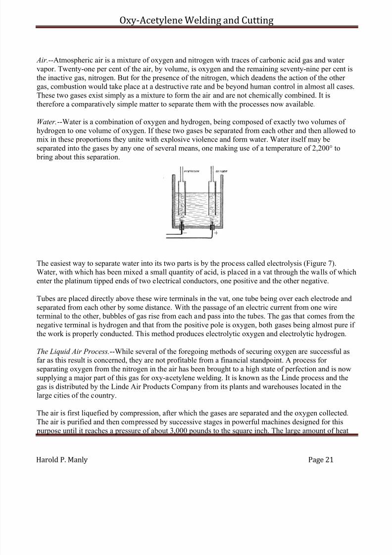
Water.--Water is a combination of oxygen and hydrogen, being composed of exactly two volumes of hydrogen to one volume of oxygen. If these two gases be separated from each other and then allowed tomix in these proportions they unite with explosive violence and form water. Water itself may beseparated into the gases by any one of several means, one making use of a temperature of 2,200° to bring about this separation.
The easiest way to separate water into its two parts is by the process called electrolysis (Figure 7).Water, with which has been mixed a small quantity of acid, is placed in a vat through the walls of whichenter the platinum tipped ends of two electrical conductors, one positive and the other negative.
Tubes are placed directly above these wire terminals in the vat, one tube being over each electrode andseparated from each other by some distance. With the passage of an electric current from one wireterminal to the other, bubbles of gas rise from each and pass into the tubes. The gas that comes from thenegative terminal is hydrogen and that from the positive pole is oxygen, both gases being almost pure if the work is properly conducted. This method produces electrolytic oxygen and electrolytic hydrogen.
The Liquid Air Process.--While several of the foregoing methods of securing oxygen are successful asfar as this result is concerned, they are not profitable from a financial standpoint. A process for separating oxygen from the nitrogen in the air has been brought to a high state of perfection and is nowsupplying a major part of this gas for oxy-acetylene welding. It is known as the Linde process and the
gas is distributed by the Linde Air Products Company from its plants and warehouses located in thelarge cities of the country.
The air is first liquefied by compression, after which the gases are separated and the oxygen collected.The air is purified and then compressed by successive stages in powerful machines designed for this purpose until it reaches a pressure of about 3,000 pounds to the square inch. The large amount of heat
7/30/2019 Oxy Acetylene Welding and Cutting
http://slidepdf.com/reader/full/oxy-acetylene-welding-and-cutting 22/106
Oxy-Acetylene Welding and Cutting
Harold P. Manly Page 22
produced is absorbed by special coolers during the process of compression. The highly compressed air is then dried and the temperature further reduced by other coolers.
The next point in the separation is that at which the air is introduced into an apparatus called an
interchanger and is allowed to escape through a valve, causing it to turn to a liquid. This liquid air issprayed onto plates and as it falls, the nitrogen return to its gaseous state and leaves the oxygen to run tothe bottom of the container. This liquid oxygen is then allowed to return to a gas and is stored in largegasometers or tanks.
The oxygen gas is taken from the storage tanks and compressed to approximately 1,800 pounds to thesquare inch, under which pressure it is passed into steel cylinders and made ready for delivery to thecustomer. This oxygen is guaranteed to be ninety-seven per cent pure.
Another process, known as the Hildebrandt process, is coming into use in this country. It is a later process and is used in Germany to a much greater extent than the Linde process. The Superior Oxygen
Co. has secured the American rights and has established several plants.
Oxygen Cylinders.--Two sizes of cylinders are in use, one containing 100 cubic feet of gas when it is atatmospheric pressure and the other containing 250 cubic feet under similar conditions. The cylinders aremade from one piece of steel and are without seams. These containers are tested at double the pressureof the gas contained to insure safety while handling.
One hundred cubic feet of oxygen weighs nearly nine pounds (8.921), and therefore the cylinders willweigh practically nine pounds more when full than after emptying, if of the 100 cubic feet size. Thelarge cylinders weigh about eighteen and one-quarter pounds more when full than when empty, makingapproximately 212 pounds empty and 230 pounds full.
The following table gives the number of cubic feet of oxygen remaining in the cylinders according tovarious gauge pressures from an initial pressure of 1,800 pounds. The amounts given are not exactlycorrect as this would necessitate lengthy calculations which would not make great enough difference toaffect the practical usefulness of the table:
Cylinder of 100 Cu. Ft. Capacity at 68° Fahr.
Gauge Volume Gauge Volume
Pressure Remaining Pressure Remaining
1800 100 700 391620 90 500 281440 80 300 171260 70 100 61080 60 18 1900 50 9 1/2
Cylinder of 250 Cu. Ft. Capacity at 68° Fahr.
7/30/2019 Oxy Acetylene Welding and Cutting
http://slidepdf.com/reader/full/oxy-acetylene-welding-and-cutting 23/106
Oxy-Acetylene Welding and Cutting
Harold P. Manly Page 23
Gauge Volume Gauge VolumePressure Remaining Pressure Remaining
1800 250 700 971620 225 500 70
1440 200 300 421260 175 100 151080 150 18 8900 125 9 1-1/4
The temperature of the cylinder affects the pressure in a large degree, the pressure increasing with a risein temperature and falling with a fall in temperature. The variation for a 100 cubic foot cylinder atvarious temperatures is given in the following tabulation:
At 150° Fahr........................ 2090 pounds.At 100° Fahr........................ 1912 pounds.At 80° Fahr........................ 1844 pounds.At 68° Fahr........................ 1800 pounds.At 50° Fahr........................ 1736 pounds.At 32° Fahr........................ 1672 pounds.At 0 Fahr........................ 1558 pounds.At -10° Fahr........................ 1522 pounds.
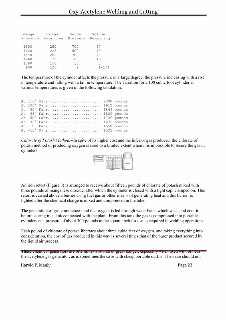
Chlorate of Potash Method.--In spite of its higher cost and the inferior gas produced, the chlorate of potash method of producing oxygen is used to a limited extent when it is impossible to secure the gas incylinders.
An iron retort (Figure 8) is arranged to receive about fifteen pounds of chlorate of potash mixed withthree pounds of manganese dioxide, after which the cylinder is closed with a tight cap, clamped on. Thisretort is carried above a burner using fuel gas or other means of generating heat and this burner islighted after the chemical charge is mixed and compressed in the tube.
The generation of gas commences and the oxygen is led through water baths which wash and cool it before storing in a tank connected with the plant. From this tank the gas is compressed into portablecylinders at a pressure of about 300 pounds to the square inch for use as required in welding operations.
Each pound of chlorate of potash liberates about three cubic feet of oxygen, and taking everything intoconsideration, the cost of gas produced in this way is several times that of the purer product secured bythe liquid air process.
These chemical generators are oftentimes a source of great danger, especially when used with or near the acetylene gas generator, as is sometimes the case with cheap portable outfits. Their use should not

7/30/2019 Oxy Acetylene Welding and Cutting
http://slidepdf.com/reader/full/oxy-acetylene-welding-and-cutting 24/106
Oxy-Acetylene Welding and Cutting
Harold P. Manly Page 24
be tolerated when any other method is available, as the danger from accident alone should prohibit the practice except when properly installed and cared for away from other sources of combustible gases.
ACETYLENE
In 1862 a chemist, Woehler, announced the discovery of the preparation of acetylene gas from calciumcarbide, which he had made by heating to a high temperature a mixture of charcoal with an alloy of zincand calcium. His product would decompose water and yield the gas. For nearly thirty years thesesubstances were neglected, with the result that acetylene was practically unknown, and up to 1892 anacetylene flame was seen by very few persons and its possibilities were not dreamed of. With thedevelopment of the modern electric furnace the possibility of calcium carbide as a commercial product became known.
In the above year, Thomas L. Willson, an electrical engineer of Spray, North Carolina, wasexperimenting in an attempt to prepare metallic calcium, for which purpose he employed an electric
furnace operating on a mixture of lime and coal tar with about ninety-five horse power. The result was amolten mass which became hard and brittle when cool. This apparently useless product was discardedand thrown in a nearby stream, when, to the astonishment of onlookers, a large volume of gas wasimmediately liberated, which, when ignited, burned with a bright and smoky flame and gave off quantities of soot. The solid material proved to be calcium carbide and the gas acetylene.
Thus, through the incidental study of a by-product, and as the result of an accident, the possibilities incarbide were made known, and in the spring of 1895 the first factory in the world for the production of this substance was established by the Willson Aluminum Company.
When water and calcium carbide are brought together an action takes place which results in the
formation of acetylene gas and slaked lime.
CARBIDE
Calcium carbide is a chemical combination of the elements carbon and calcium, being dark brown, black or gray with sometimes a blue or red tinge. It looks like stone and will only burn when heatedwith oxygen.
Calcium carbide may be preserved for any length of time if protected from the air, but the ordinarymoisture in the atmosphere gradually affects it until nothing remains but slaked lime. It always possesses a penetrating odor, which is not due to the carbide itself but to the fact that it is being
constantly affected by moisture and producing small quantities of acetylene gas.
This material is not readily dissolved by liquids, but if allowed to come in contact with water, adecomposition takes place with the evolution of large quantities of gas. Carbide is not affected byshock, jarring or age.
7/30/2019 Oxy Acetylene Welding and Cutting
http://slidepdf.com/reader/full/oxy-acetylene-welding-and-cutting 25/106
Oxy-Acetylene Welding and Cutting
Harold P. Manly Page 25
A pound of absolutely pure carbide will yield five and one-half cubic feet of acetylene. Absolute puritycannot be attained commercially, and in practice good carbide will produce from four and one-half tofive cubic feet for each pound used.
Carbide is prepared by fusing lime and carbon in the electric furnace under a heat in excess of 6,000degrees Fahrenheit. These materials are among the most difficult to melt that are known. Lime is soinfusible that it is frequently employed for the materials of crucibles in which the highest melting metalsare fused, and for the pencils in the calcium light because it will stand extremely high temperatures.
Carbon is the material employed in the manufacture of arc light electrodes and other electricalappliances that must stand extreme heat. Yet these two substances are forced into combination in themanufacture of calcium carbide. It is the excessively high temperature attainable in the electric furnacethat causes this combination and not any effect of the electricity other than the heat produced.
A mixture of ground coke and lime is introduced into the furnace through which an electric arc has been
drawn. The materials unite and form an ingot of very pure carbide surrounded by a crust of less purity.The poorer crust is rejected in breaking up the mass into lumps which are graded according to their size.The largest size is 2 by 3-1/2 inches and is called "lump," a medium size is 1/2 by 2 inches and is called"egg," an intermediate size for certain types of generators is 3/8 by 1-1/4 inches and called "nut," andthe finely crushed pieces for use in still other types of generators are 1/12 by 1/4 inch in size and arecalled "quarter." Instructions as to the size best suited to different generators are furnished by themakers of those instruments.
These sizes are packed in air-tight sheet steel drums containing 100 pounds each. The Union CarbideCompany of Chicago and New York, operating under patents, manufactures and distributes the supplyof calcium carbide for the entire United States. Plants for this manufacture are established at Niagara
Falls, New York, and Sault Ste. Marie, Michigan. This company maintains a system of warehouses inmore than one hundred and ten cities, where large stocks of all sizes are carried.
The National Board of Fire Underwriters gives the following rules for the storage of carbide:
Calcium carbide in quantities not to exceed six hundred pounds may be stored, when contained inapproved metal packages not to exceed one hundred pounds each, inside insured property, provided thatthe place of storage be dry, waterproof and well ventilated and also provided that all but one of the packages in any one building shall be sealed and that seals shall not be broken so long as there iscarbide in excess of one pound in any other unsealed package in the building.
Calcium carbide in quantities in excess of six hundred pounds must be stored above ground in detached buildings, used exclusively for the storage of calcium carbide, in approved metal packages, and such buildings shall be constructed to be dry, waterproof and well ventilated.
Properties of Acetylene.--This gas is composed of twenty-four parts of carbon and two parts of hydrogen by weight and is classed with natural gas, petroleum, etc., as one of the hydrocarbons. Thisgas contains the highest percentage of carbon known to exist in any combination of this form and it may

7/30/2019 Oxy Acetylene Welding and Cutting
http://slidepdf.com/reader/full/oxy-acetylene-welding-and-cutting 26/106
Oxy-Acetylene Welding and Cutting
Harold P. Manly Page 26
therefore be considered as gaseous carbon. Carbon is the fuel that is used in all forms of combustion andis present in all fuels from whatever source or in whatever form. Acetylene is therefore the most powerful of all fuel gases and is able to give to the torch flame in welding the highest temperature of any flame.
Acetylene is a colorless and tasteless gas, possessed of a peculiar and penetrating odor. The least tracein the air of a room is easily noticed, and if this odor is detected about an apparatus in operation, it iscertain to indicate a leakage of gas through faulty piping, open valves, broken hose or otherwise. Thisleakage must be prevented before proceeding with the work to be done.
All gases which burn in air will, when mixed with air previous to ignition, produce more or less violentexplosions, if fired. To this rule acetylene is no exception. One measure of acetylene and twelve andone-half of air are required for complete combustion; this is therefore the proportion for the most perfectexplosion. This is not the only possible mixture that will explode, for all proportions from three to thirty per cent of acetylene in air will explode with more or less force if ignited.
The igniting point of acetylene is lower than that of coal gas, being about 900 degrees Fahrenheit asagainst eleven hundred degrees for coal gas. The gas issuing from a torch will ignite if allowed to playon the tip of a lighted cigar.
It is still further true that acetylene, at some pressures, greater than normal, has under most favorableconditions for the effect, been found to explode; yet it may be stated with perfect confidence that under no circumstances has anyone ever secured an explosion in it when subjected to pressures not exceedingfifteen pounds to the square inch.
Although not exploded by the application of high heat, acetylene is injured by such treatment. It is
partly converted, by high heat, into other compounds, thus lessening the actual quantity of the gas,wasting it and polluting the rest by the introduction of substances which do not belong there. Thesecompounds remain in part with the gas, causing it to burn with a persistent smoky flame and with thedeposit of objectionable tarry substances. Where the gas is generated without undue rise of temperaturethese difficulties are avoided.
Purification of Acetylene.--Impurities in this gas are caused by impurities in the calcium carbide fromwhich it is made or by improper methods and lack of care in generation. Impurities from the materialwill be considered first.
Impurities in the carbide may be further divided into two classes: those which exert no action on water
and those which act with the water to throw off other gaseous products which remain in the acetylene.Those impurities which exert no action on the water consist of coke that has not been changed in thefurnace and sand and some other substances which are harmless except that they increase the ash leftafter the acetylene has been generated.
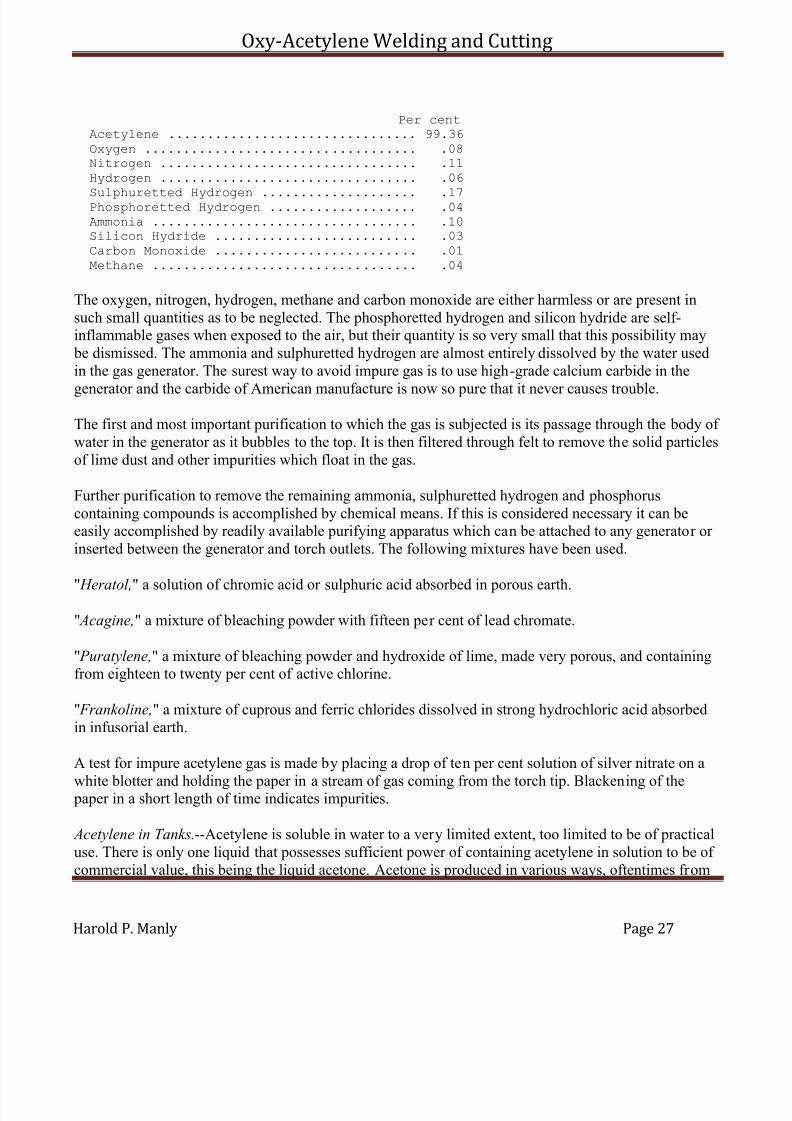
An analysis of the gas coming from a typical generator is as follows:
7/30/2019 Oxy Acetylene Welding and Cutting
http://slidepdf.com/reader/full/oxy-acetylene-welding-and-cutting 27/106
Oxy-Acetylene Welding and Cutting
Harold P. Manly Page 27
Per centAcetylene ................................ 99.36
Oxygen ................................... .08Nitrogen ................................. .11Hydrogen ................................. .06
Sulphuretted Hydrogen .................... .17Phosphoretted Hydrogen ................... .04Ammonia .................................. .10Silicon Hydride .......................... .03Carbon Monoxide .......................... .01Methane .................................. .04
The oxygen, nitrogen, hydrogen, methane and carbon monoxide are either harmless or are present insuch small quantities as to be neglected. The phosphoretted hydrogen and silicon hydride are self-inflammable gases when exposed to the air, but their quantity is so very small that this possibility may be dismissed. The ammonia and sulphuretted hydrogen are almost entirely dissolved by the water usedin the gas generator. The surest way to avoid impure gas is to use high-grade calcium carbide in the
generator and the carbide of American manufacture is now so pure that it never causes trouble.
The first and most important purification to which the gas is subjected is its passage through the body of water in the generator as it bubbles to the top. It is then filtered through felt to remove the solid particlesof lime dust and other impurities which float in the gas.
Further purification to remove the remaining ammonia, sulphuretted hydrogen and phosphoruscontaining compounds is accomplished by chemical means. If this is considered necessary it can beeasily accomplished by readily available purifying apparatus which can be attached to any generator or inserted between the generator and torch outlets. The following mixtures have been used.
" Heratol," a solution of chromic acid or sulphuric acid absorbed in porous earth.
" Acagine," a mixture of bleaching powder with fifteen per cent of lead chromate.
" Puratylene," a mixture of bleaching powder and hydroxide of lime, made very porous, and containingfrom eighteen to twenty per cent of active chlorine.
" Frankoline," a mixture of cuprous and ferric chlorides dissolved in strong hydrochloric acid absorbedin infusorial earth.
A test for impure acetylene gas is made by placing a drop of ten per cent solution of silver nitrate on a
white blotter and holding the paper in a stream of gas coming from the torch tip. Blackening of the paper in a short length of time indicates impurities.
Acetylene in Tanks.--Acetylene is soluble in water to a very limited extent, too limited to be of practicaluse. There is only one liquid that possesses sufficient power of containing acetylene in solution to be of commercial value, this being the liquid acetone. Acetone is produced in various ways, oftentimes from
7/30/2019 Oxy Acetylene Welding and Cutting
http://slidepdf.com/reader/full/oxy-acetylene-welding-and-cutting 28/106
Oxy-Acetylene Welding and Cutting
Harold P. Manly Page 28
the distillation of wood. It is a transparent, colorless liquid that flows with ease. It boils at 133°Fahrenheit, is inflammable and burns with a luminous flame. It has a peculiar but rather agreeable odor.
Acetone dissolves twenty-four times its own bulk of acetylene at ordinary atmospheric pressure. If this
pressure is increased to two atmospheres, 14.7 pounds above ordinary pressure, it will dissolve justtwice as much of the gas and for each atmosphere that the pressure is increased it will dissolve as muchmore.
If acetylene be compressed above fifteen pounds per square inch at ordinary temperature without first being dissolved in acetone a danger is present of self-ignition. This danger, while practically nothing atfifteen pounds, increases with the pressure until at forty atmospheres it is very explosive. Mixed withacetone, the gas loses this dangerous property and is safe for handling and transportation. As acetyleneis dissolved in the liquid the acetone increases its volume slightly so that when the gas has been drawnout of a closed tank a space is left full of free acetylene.
This last difficulty is removed by first filling the cylinder or tank with some porous material, such asasbestos, wood charcoal, infusorial earth, etc. Asbestos is used in practice and by a system of packingand supporting the absorbent material no space is left for the free gas, even when the acetylene has beencompletely withdrawn.
The acetylene is generated in the usual way and is washed, purified and dried. Great care is used tomake the gas as free as possible from all impurities and from air. The gas is forced into containers filledwith acetone as described and is compressed to one hundred and fifty pounds to the square inch. Fromthese tanks it is transferred to the smaller portable cylinders for consumers' use.
The exact volume of gas remaining in a cylinder at atmospheric temperature may be calculated if the
weight of the cylinder empty is known. One pound of the gas occupies 13.6 cubic feet, so that if thedifference in weight between the empty cylinder and the one considered be multiplied by 13.6. the resultwill be the number of cubic feet of gas contained.
The cylinders contain from 100 to 500 cubic feet of acetylene under pressure. They cannot be filled withthe ordinary type of generator as they require special purifying and compressing apparatus, whichshould never be installed in any building where other work is being carried on, or near other buildingswhich are occupied, because of the danger of explosion.
Dissolved acetylene is manufactured by the Prest-O-Lite Company, the Commercial AcetyleneCompany and the Searchlight Gas Company and is distributed from warehouses in various cities.
These tanks should not be discharged at a rate per hour greater than one-seventh of their total capacity,that is, from a tank of 100 cubic feet capacity, the discharge should not be more than fourteen cubic feet per hour. If discharge is carried on at an excessive rate the acetone is drawn out with the gas and reducesthe heat of the welding flame.
7/30/2019 Oxy Acetylene Welding and Cutting
http://slidepdf.com/reader/full/oxy-acetylene-welding-and-cutting 29/106
Oxy-Acetylene Welding and Cutting
Harold P. Manly Page 29
For this reason welding should not be attempted with cylinders designed for automobile and boatlighting. When the work demands a greater delivery than one of the larger tanks will give, two or moretanks may be connected with a special coupler such as may be secured from the makers and distributersof the gas. These couplers may be arranged for two, three, four or five tanks in one battery by removing
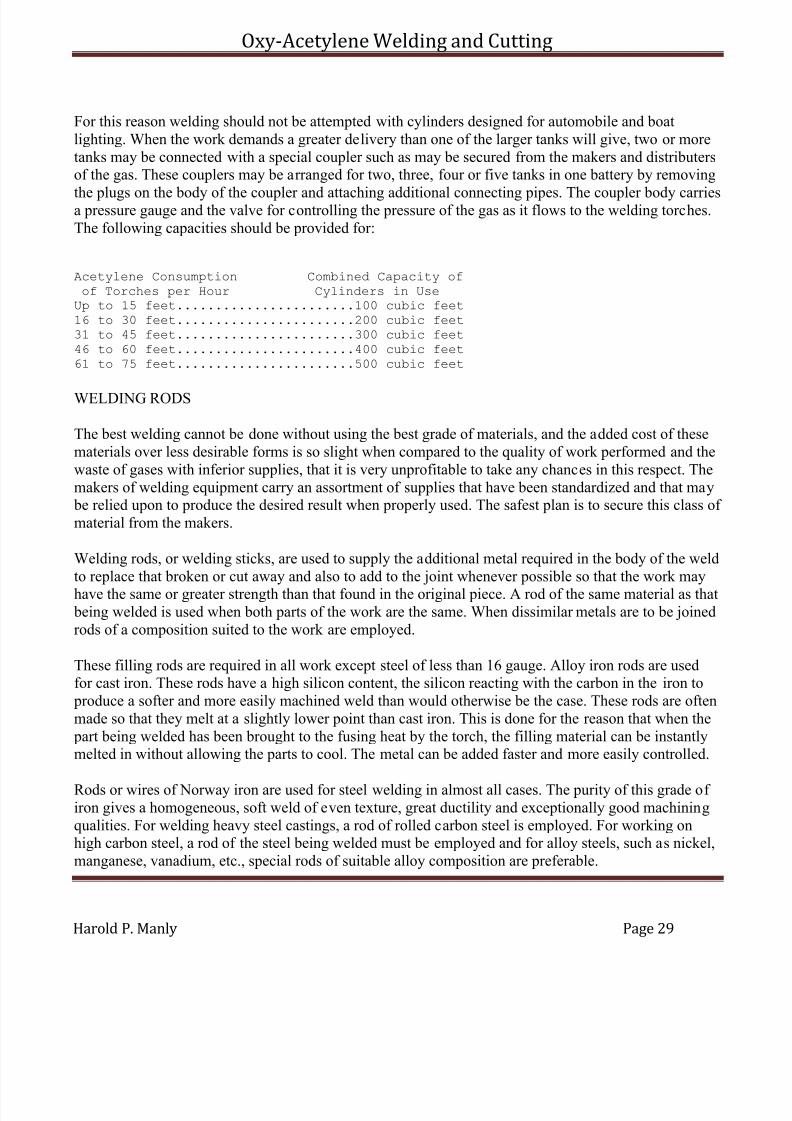
the plugs on the body of the coupler and attaching additional connecting pipes. The coupler body carriesa pressure gauge and the valve for controlling the pressure of the gas as it flows to the welding torches.The following capacities should be provided for:
Acetylene Consumption Combined Capacity ofof Torches per Hour Cylinders in UseUp to 15 feet.......................100 cubic feet16 to 30 feet.......................200 cubic feet31 to 45 feet.......................300 cubic feet46 to 60 feet.......................400 cubic feet61 to 75 feet.......................500 cubic feet
WELDING RODS
The best welding cannot be done without using the best grade of materials, and the added cost of thesematerials over less desirable forms is so slight when compared to the quality of work performed and thewaste of gases with inferior supplies, that it is very unprofitable to take any chances in this respect. Themakers of welding equipment carry an assortment of supplies that have been standardized and that may be relied upon to produce the desired result when properly used. The safest plan is to secure this class of material from the makers.
Welding rods, or welding sticks, are used to supply the additional metal required in the body of the weldto replace that broken or cut away and also to add to the joint whenever possible so that the work may
have the same or greater strength than that found in the original piece. A rod of the same material as that being welded is used when both parts of the work are the same. When dissimilar metals are to be joinedrods of a composition suited to the work are employed.
These filling rods are required in all work except steel of less than 16 gauge. Alloy iron rods are usedfor cast iron. These rods have a high silicon content, the silicon reacting with the carbon in the iron to produce a softer and more easily machined weld than would otherwise be the case. These rods are oftenmade so that they melt at a slightly lower point than cast iron. This is done for the reason that when the part being welded has been brought to the fusing heat by the torch, the filling material can be instantlymelted in without allowing the parts to cool. The metal can be added faster and more easily controlled.
Rods or wires of Norway iron are used for steel welding in almost all cases. The purity of this grade of iron gives a homogeneous, soft weld of even texture, great ductility and exceptionally good machiningqualities. For welding heavy steel castings, a rod of rolled carbon steel is employed. For working onhigh carbon steel, a rod of the steel being welded must be employed and for alloy steels, such as nickel,manganese, vanadium, etc., special rods of suitable alloy composition are preferable.

7/30/2019 Oxy Acetylene Welding and Cutting
http://slidepdf.com/reader/full/oxy-acetylene-welding-and-cutting 30/106
Oxy-Acetylene Welding and Cutting
Harold P. Manly Page 30
Aluminum welding rods are made from this metal alloyed to give the even flowing that is essential.Aluminum is one of the most difficult of all the metals to handle in this work and the selection of the proper rod is of great importance.
Brass is filled with brass wire when in small castings and sheets. For general work with brass castings,manganese bronze or Tobin bronze may be used.
Bronze is welded with manganese bronze or Tobin bronze, while copper is filled with copper wire.
These welding rods should always be used to fill the weld when the thickness of material makes their employment necessary, and additional metal should always be added at the weld when possible as the joint cannot have the same strength as the original piece if made or dressed off flush with the surfacesaround the weld. This is true because the metal welded into the joint is a casting and will never havemore strength than a casting of the material used for filling.
Great care should be exercised when adding metal from welding rods to make sure that no metal isadded at a point that is not itself melted and molten when the addition is made. When molten metal is placed upon cooler surfaces the result is not a weld but merely a sticking together of the two partswithout any strength in the joint.
FLUXES
Difficulty would be experienced in welding with only the metal and rod to work with because of thescale that forms on many materials under heat, the oxides of other metals and the impurities found inalmost all metals. These things tend to prevent a perfect joining of the metals and some means arenecessary to prevent their action.
Various chemicals, usually in powder form, are used to accomplish the result of cleaning the weld andmaking the work of the operator less difficult. They are called fluxes.
A flux is used to float off physical impurities from the molten metal; to furnish a protecting coatingaround the weld; to assist in the removal of any objectionable oxide of the metals being handled; tolower the temperature at which the materials flow; to make a cleaner weld and to produce a better quality of metal in the finished work.
The flux must be of such composition that it will accomplish the desired result without introducing newdifficulties. They may be prepared by the operator in many cases or may be secured from the makers of
welding apparatus, the same remarks applying to their quality as were made regarding the welding rods,that is, only the best should be considered.
The flux used for cast iron should have a softening effect and should prevent burning of the metal. Inmany cases it is possible and even preferable to weld cast iron without the use of a flux, and in anyevent the smaller the quantity used the better the result should be. Flux should not be added just before

7/30/2019 Oxy Acetylene Welding and Cutting
http://slidepdf.com/reader/full/oxy-acetylene-welding-and-cutting 31/106
Oxy-Acetylene Welding and Cutting
Harold P. Manly Page 31
the completion of the work because the heat will not have time to drive the added elements out of themetal or to incorporate them with the metal properly.
Aluminum should never be welded without using a flux because of the oxide formed. This oxide, called
alumina, does not melt until a heat of 5,000° Fahrenheit is reached, four times the heat needed to meltthe aluminum itself. It is necessary that this oxide be broken down or dissolved so that the aluminummay have a chance to flow together. Copper is another metal that requires a flux because of its rapidoxidation under heat.
While the flux is often thrown or sprinkled along the break while welding, much better results will beobtained by dipping the hot end of the welding rod into the flux whenever the work needs it. Sufficient powder will stick on the end of the rod for all purposes, and with some fluxes too much will adhere.Care should always be used to avoid the application of excessive flux, as this is usually worse thanusing too little.
SUPPLIES AND FIXTURES
Goggles.--The oxy-acetylene torch should not be used without the protection to the eyes afforded bygoggles. These not only relieve unnecessary strain, but make it much easier to watch the exact progressof the work with the molten metal. The difficulty of protecting the sight while welding is even greater than when cutting metal with the torch.
Acetylene gives a light which is nearest to sunlight of any artificial illuminant. But for the fact that thisgas light gives a little more green and less blue in its composition, it would be the same in quality and practically the same in intensity. This light from the gas is almost absent during welding, being lost withthe addition of the extra oxygen needed to produce the welding heat. The light that is dangerous comes
from the molten metal which flows under the torch at a bright white heat.
Goggles for protection against this light and the heat that goes with it may be secured in various tints,the darker glass being for welding and the lighter for cutting. Those having frames in which the metal parts do not touch the flesh directly are most desirable because of the high temperature reached by these parts.
Gloves.--While not as necessary as are the goggles, gloves are a convenience in many cases. Those inwhich leather touches the hands directly are really of little value as the heat that protection is desiredagainst makes the leather so hot that nothing is gained in comfort. Gloves are made with asbestos cloth,which are not open to this objection in so great a degree.
7/30/2019 Oxy Acetylene Welding and Cutting
http://slidepdf.com/reader/full/oxy-acetylene-welding-and-cutting 32/106
Oxy-Acetylene Welding and Cutting
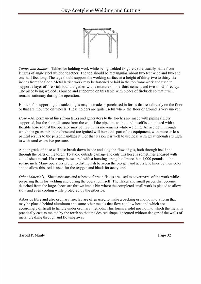
Harold P. Manly Page 32
Tables and Stands.--Tables for holding work while being welded (Figure 9) are usually made fromlengths of angle steel welded together. The top should be rectangular, about two feet wide and two andone-half feet long. The legs should support the working surface at a height of thirty-two to thirty-sixinches from the floor. Metal lattice work may be fastened or laid in the top framework and used tosupport a layer of firebrick bound together with a mixture of one-third cement and two-thirds fireclay.The piece being welded is braced and supported on this table with pieces of firebrick so that it willremain stationary during the operation.
Holders for supporting the tanks of gas may be made or purchased in forms that rest directly on the floor or that are mounted on wheels. These holders are quite useful where the floor or ground is very uneven.
Hose.--All permanent lines from tanks and generators to the torches are made with piping rigidlysupported, but the short distance from the end of the pipe line to the torch itself is completed with aflexible hose so that the operator may be free in his movements while welding. An accident throughwhich the gases mix in the hose and are ignited will burst this part of the equipment, with more or less painful results to the person handling it. For that reason it is well to use hose with great enough strengthto withstand excessive pressure.
A poor grade of hose will also break down inside and clog the flow of gas, both through itself andthrough the parts of the torch. To avoid outside damage and cuts this hose is sometimes encased withcoiled sheet metal. Hose may be secured with a bursting strength of more than 1,000 pounds to thesquare inch. Many operators prefer to distinguish between the oxygen and acetylene lines by their color and to allow this, red is used for the oxygen and black for acetylene.
Other Materials.--Sheet asbestos and asbestos fibre in flakes are used to cover parts of the work while preparing them for welding and during the operation itself. The flakes and small pieces that becomedetached from the large sheets are thrown into a bin where the completed small work is placed to allowslow and even cooling while protected by the asbestos.
Asbestos fibre and also ordinary fireclay are often used to make a backing or mould into a form thatmay be placed behind aluminum and some other metals that flow at a low heat and which areaccordingly difficult to handle under ordinary methods. This forms a solid mould into which the metal is practically cast as melted by the torch so that the desired shape is secured without danger of the walls of metal breaking through and flowing away.
7/30/2019 Oxy Acetylene Welding and Cutting
http://slidepdf.com/reader/full/oxy-acetylene-welding-and-cutting 33/106
Oxy-Acetylene Welding and Cutting
Harold P. Manly Page 33
Carbon blocks and rods are made in various shapes and sizes so that they may be used to fill threadedholes and other places that it is desired to protect during welding. These may be secured in rods of various diameters up to one inch and in blocks of several different dimensions.
7/30/2019 Oxy Acetylene Welding and Cutting
http://slidepdf.com/reader/full/oxy-acetylene-welding-and-cutting 34/106
Oxy-Acetylene Welding and Cutting
Harold P. Manly Page 34
CHAPTER III
ACETYLENE GENERATORS
Acetylene generators used for producing the gas from the action of water on calcium carbide are dividedinto three principal classes according to the pressure under which they operate.
Low pressure generators are designed to operate at one pound or less per square inch. Medium pressuresystems deliver the gas at not to exceed fifteen pounds to the square inch while high pressure typesfurnish gas above fifteen pounds per square inch. High pressure systems are almost unknown in thiscountry, the medium pressure type being often referred to as "high pressure."
Another important distinction is formed by the method of bringing the carbide and water together. Themajority of those now in use operate by dropping small quantities of carbide into a large volume of
water, allowing the generated gas to bubble up through the water before being collected above thesurface. This type is known as the "carbide to water" generator.
A less used type brings a measured and small quantity of water to a comparatively large body of thecarbide, the gas being formed and collected from the chamber in which the action takes place. This iscalled the "water to carbide" type. Another way of expressing the difference in feed is that of designating the two types as "carbide feed" for the former and "water feed" for the latter.
A further division of the carbide to water machines is made by mentioning the exact method of feedingthe carbide. One type, called "gravity feed" operates by allowing the carbide to escape and fall by theaction of its own weight, or gravity; the other type, called "forced feed," includes a separate mechanismdriven by power. This mechanism feeds definite amounts of the carbide to the water as required by thedemands on the generator. The action of either feed is controlled by the withdrawal of gas from thegenerator, the aim being to supply sufficient carbide to maintain a nearly constant supply.
Generator Requirements.--The qualities of a good generator are outlined as follows: [Footnote: SeePond's "Calcium Carbide and Acetylene."]
It must allow no possibility of the existence of an explosive mixture in any of its parts at any time. It isnot enough to argue that a mixture, even if it exists, cannot be exploded unless kindled. It is necessary todemand that a dangerous mixture can at no time be formed, even if the machine is tampered with by anignorant person. The perfect machine must be so constructed that it shall be impossible at any time,under any circumstances, to blow it up.
It must insure cool generation. Since this is a relative term, all machines being heated somewhat duringthe generation of gas, this amounts to saying that a machine must heat but little. A pound of carbidedecomposed by water develops the same amount of heat under all circumstances, but that heat can beallowed to increase locally to a high point, or it can be equalized by water so that no part of the material becomes heated enough to do damage.

7/30/2019 Oxy Acetylene Welding and Cutting
http://slidepdf.com/reader/full/oxy-acetylene-welding-and-cutting 35/106
Oxy-Acetylene Welding and Cutting
Harold P. Manly Page 35
It must be well constructed. A good generator does not need, perhaps, to be "built like a watch," but itshould be solid, substantial and of good material. It should be built for service, to last and not simply tosell; anything short of this is to be avoided as unsafe and unreliable.
It must be simple. The more complicated the machine the sooner it will get out of order. Understandyour generator. Know what is inside of it and beware of an apparatus, however attractive its exterior,whose interior is filled with pipes and tubes, valves and diaphragms whose functions you do not perfectly understand.
It should be capable of being cleaned and recharged and of receiving all other necessary attentionwithout loss of gas, both for economy's sake, and more particularly to avoid danger of fire.
It should require little attention. All machines have to be emptied and recharged periodically; but themore this process is simplified and the more quickly this can be accomplished, the better.
It should be provided with a suitable indicator to designate how low the charge is in order that therefilling may be done in good season.
It should completely use up the carbide, generating the maximum amount of gas.
Overheating.--A large amount of heat is liberated when acetylene gas is formed from the union of calcium carbide and water. Overheating during this process, that is to say, an intense local heat rather than a large amount of heat well distributed, brings about the phenomenon of polymerization,converting the gas, or part of it, into oily matters, which can do nothing but harm. This tarry masscoming through the small openings in the torches causes them to become partly closed and alters the proportions of the gases to the detriment of the welding flame. The only remedy for this trouble is to
avoid its cause and secure cool generation.
Overheating can be detected by the appearance of the sludge remaining after the gas has been made.Discoloration, yellow or brown, shows that there has been trouble in this direction and the resultanteffects at the torches may be looked for. The abundance of water in the carbide to water machineseffects this cooling naturally and is a characteristic of well designed machines of this class. It has beenfound best and has practically become a fundamental rule of generation that a gallon of water must be provided for each pound of carbide placed in the generator. With this ratio and a generator large enoughfor the number of torches to be supplied, little trouble need be looked for with overheating.
Water to Carbide Generators.--It is, of course, much easier to obtain a measured and regular flow of
water than to obtain such a flow of any solid substance, especially when the solid substance is in theform of lumps, as is carbide This fact led to the use of a great many water-feed generators for all classesof work, and this type is still in common use for the small portable machines, such, for instance, as thoseused on motor cars for the lamps. The water-feed machine is not, however, favored for welding plants,as is the carbide feed, in spite of the greater difficulties attending the handling of the solid material.
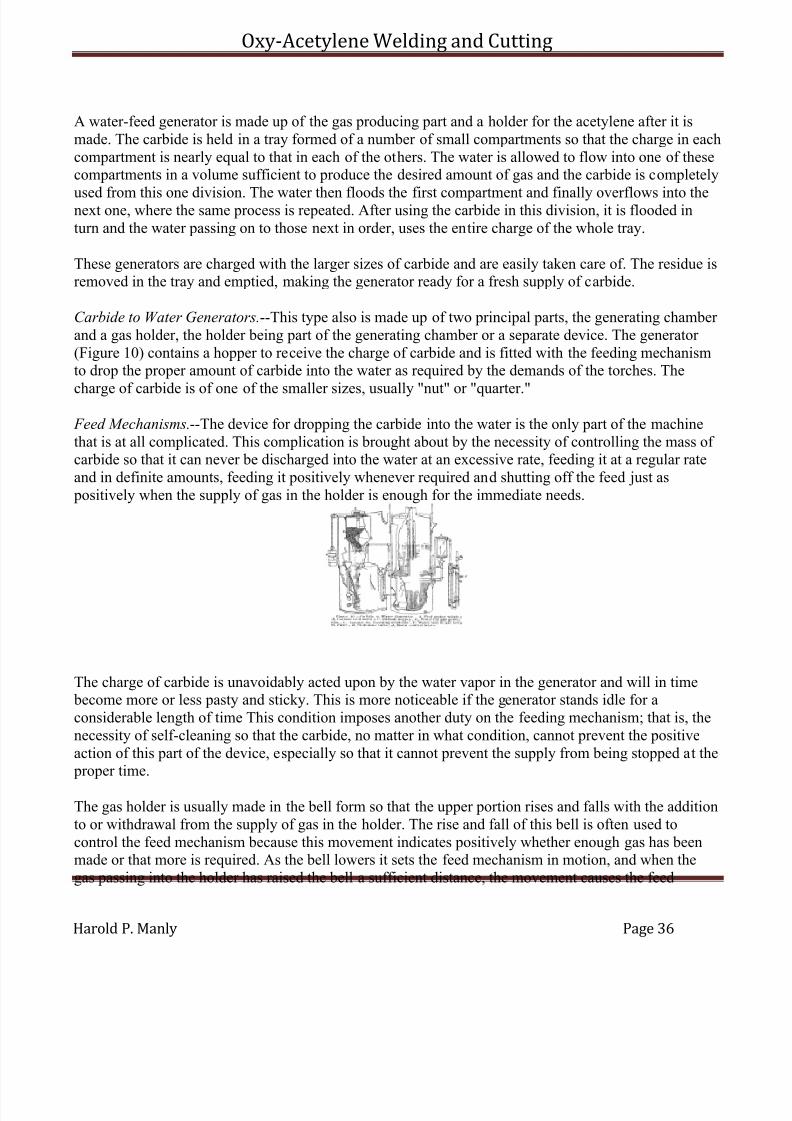
7/30/2019 Oxy Acetylene Welding and Cutting
http://slidepdf.com/reader/full/oxy-acetylene-welding-and-cutting 36/106
Oxy-Acetylene Welding and Cutting
Harold P. Manly Page 36
A water-feed generator is made up of the gas producing part and a holder for the acetylene after it ismade. The carbide is held in a tray formed of a number of small compartments so that the charge in eachcompartment is nearly equal to that in each of the others. The water is allowed to flow into one of thesecompartments in a volume sufficient to produce the desired amount of gas and the carbide is completely
used from this one division. The water then floods the first compartment and finally overflows into thenext one, where the same process is repeated. After using the carbide in this division, it is flooded inturn and the water passing on to those next in order, uses the entire charge of the whole tray.
These generators are charged with the larger sizes of carbide and are easily taken care of. The residue isremoved in the tray and emptied, making the generator ready for a fresh supply of carbide.
Carbide to Water Generators.--This type also is made up of two principal parts, the generating chamber and a gas holder, the holder being part of the generating chamber or a separate device. The generator (Figure 10) contains a hopper to receive the charge of carbide and is fitted with the feeding mechanismto drop the proper amount of carbide into the water as required by the demands of the torches. The
charge of carbide is of one of the smaller sizes, usually "nut" or "quarter."
Feed Mechanisms.--The device for dropping the carbide into the water is the only part of the machinethat is at all complicated. This complication is brought about by the necessity of controlling the mass of carbide so that it can never be discharged into the water at an excessive rate, feeding it at a regular rateand in definite amounts, feeding it positively whenever required and shutting off the feed just as positively when the supply of gas in the holder is enough for the immediate needs.
The charge of carbide is unavoidably acted upon by the water vapor in the generator and will in time become more or less pasty and sticky. This is more noticeable if the generator stands idle for aconsiderable length of time This condition imposes another duty on the feeding mechanism; that is, thenecessity of self-cleaning so that the carbide, no matter in what condition, cannot prevent the positiveaction of this part of the device, especially so that it cannot prevent the supply from being stopped at the proper time.
The gas holder is usually made in the bell form so that the upper portion rises and falls with the additionto or withdrawal from the supply of gas in the holder. The rise and fall of this bell is often used tocontrol the feed mechanism because this movement indicates positively whether enough gas has beenmade or that more is required. As the bell lowers it sets the feed mechanism in motion, and when thegas passing into the holder has raised the bell a sufficient distance, the movement causes the feed
7/30/2019 Oxy Acetylene Welding and Cutting
http://slidepdf.com/reader/full/oxy-acetylene-welding-and-cutting 37/106
Oxy-Acetylene Welding and Cutting
Harold P. Manly Page 37
mechanism to stop the fall of carbide into the water. In practice, the movement of this part of the holder is held within very narrow limits.
Gas Holders.--No matter how close the adjustment of the feeding device, there will always be a slight
amount of gas made after the fall of carbide is stopped, this being caused by the evolution of gas fromthe carbide with which water is already in contact. This action is called "after generation" and the gasholder in any type of generator must provide sufficient capacity to accommodate this excess gas. As ageneral rule the water to carbide generator requires a larger gas holder than the carbide to water type because of the greater amount of carbide being acted upon by the water at any one time, also becausethe surface of carbide presented to the moist air within the generating chamber is greater with this type.
Freezing.--Because of the rather large body of water contained in any type of generator, there is alwaysdanger of its freezing and rendering the device inoperative unless placed in a temperature above thefreezing point of the water. It is, of course, dangerous and against the insurance rules to place agenerator in the same room with a fire of any kind, but the room may be heated by steam or hot water
coils from a furnace in another building or in another part of the same building.
When the generator is housed in a separate structure the walls should be made of materials or construction that prevents the passage of heat or cold through them to any great extent. This may beaccomplished by the use of hollow tile or concrete blocks or by any other form of double wall providingair spaces between the outer and inner facings. The space between the parts of the wall may be filledwith materials that further retard the loss of heat if this is necessary under the conditions prevailing.
Residue From Generators.--The sludge remaining in the carbide to water generator may be drawn off into the sewer if the piping is run at a slant great enough to give a fall that carries the whole quantity, both water and ash, away without allowing settling and consequent clogging. Generators are provided
with agitators which are operated to stir the ash up with the water so that the whole mass is carried off when the drain cock is opened.
If sewer connections cannot be made in such a way that the ash is entirely carried away, it is best to runthe liquid mass into a settling basin outside of the building. This should be in the form of a shallow pitwhich will allow the water to pass off by soaking into the ground and by evaporation, leaving thecomparatively dry ash in the pit. This ash which remains is essentially slaked lime and can often bedisposed of to more or less advantage to be used in mortar, whitewash, marking paths and any other usefor which slaked lime is suited. The disposition of the ash depends entirely on local conditions. Anaverage analysis of this ash is as follows:
Sand....................... 1.10 per cent.Carbon..................... 2.72 "Oxide of iron and alumina.. 2.77 "Lime....................... 64.06 "Water and carbonic acid.... 29.35 "
------100.00

7/30/2019 Oxy Acetylene Welding and Cutting
http://slidepdf.com/reader/full/oxy-acetylene-welding-and-cutting 38/106
Oxy-Acetylene Welding and Cutting
Harold P. Manly Page 38
GENERATOR CONSTRUCTION
The water for generating purposes is carried in the large tank-like compartment directly below thecarbide chamber. See Figure 11. This water compartment is filled through a pipe of such a height that
the water level cannot be brought above the proper point or else the water compartment is provided witha drain connection which accomplishes this same result by allowing an excess to flow away.
The quantity of water depends on the capacity of the generator inasmuch as there must be one gallon for each pound of carbide required. The generator should be of sufficient capacity to furnish gas under working conditions from one charge of carbide to all torches installed for at least five hours continuoususe.
After calculating the withdrawal of the whole number of torches according to the work they are to do for this period of five hours the proper generator capacity may be found on the basis of one cubic foot of gas per hour for each pound of carbide. Thus if the torches were to use sixty cubic feet of gas per hour,
five hours would call for three hundred cubic feet and a three hundred pound generator should beinstalled. Generators are rated according to their carbide capacity in pounds.
Charging.--The carbide capacity of the generator should be great enough to furnish a continuous supplyof gas for the maximum operating time, basing the quantity of gas generated on four and one-half cubicfeet from each pound of lump carbide and on four cubic feet from each pound of quarter, intermediatesizes being in proportion.
Generators are built in such a way that it is impossible for the acetylene to escape from the gas holdingcompartment during the recharging process. This is accomplished (1) by connecting the water inlet pipeopening with a shut off valve in such a way that the inlet cannot be uncovered or opened without first
closing the shut off valve with the same movement of the operator; (2) by incorporating an automatic or hydraulic one-way valve so that this valve closes and acts as a check when the gas attempts to flow fromthe holder back to the generating chamber, or by any other means that will positively accomplish thisresult.
In generators having no separate gas holding chamber but carrying the supply in the same compartmentin which it is generated, the gas contained under pressure is allowed to escape through vent pipes intothe outside air before recharging with carbide. As in the former case, the parts are so interlocked that itis impossible to introduce carbide or water without first allowing the escape of the gas in the generator.
It is required by the insurance rules that the entire change of carbide while in the generator be held in
such a way that it may be entirely removed without difficulty in case the necessity should arise.
Generators should be cleaned and recharged at regular stated intervals. This work should be done duringdaylight hours only and likewise all repairs should be made at such a time that artificial light is notneeded. Where it is absolutely necessary to use artificial light it should be provided only byincandescent electric lamps enclosed in gas tight globes.
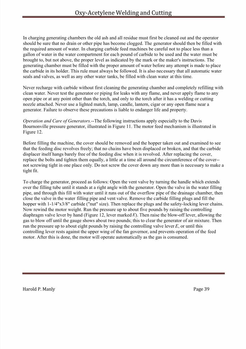
7/30/2019 Oxy Acetylene Welding and Cutting
http://slidepdf.com/reader/full/oxy-acetylene-welding-and-cutting 39/106
Oxy-Acetylene Welding and Cutting
Harold P. Manly Page 39
In charging generating chambers the old ash and all residue must first be cleaned out and the operator should be sure that no drain or other pipe has become clogged. The generator should then be filled withthe required amount of water. In charging carbide feed machines be careful not to place less than agallon of water in the water compartment for each pound of carbide to be used and the water must be
brought to, but not above, the proper level as indicated by the mark or the maker's instructions. Thegenerating chamber must be filled with the proper amount of water before any attempt is made to placethe carbide in its holder. This rule must always be followed. It is also necessary that all automatic water seals and valves, as well as any other water tanks, be filled with clean water at this time.
Never recharge with carbide without first cleaning the generating chamber and completely refilling withclean water. Never test the generator or piping for leaks with any flame, and never apply flame to anyopen pipe or at any point other than the torch, and only to the torch after it has a welding or cuttingnozzle attached. Never use a lighted match, lamp, candle, lantern, cigar or any open flame near agenerator. Failure to observe these precautions is liable to endanger life and property.
Operation and Care of Generators.--The following instructions apply especially to the DavisBournonville pressure generator, illustrated in Figure 11. The motor feed mechanism is illustrated inFigure 12.
Before filling the machine, the cover should be removed and the hopper taken out and examined to seethat the feeding disc revolves freely; that no chains have been displaced or broken, and that the carbidedisplacer itself hangs barely free of the feeding disc when it is revolved. After replacing the cover,replace the bolts and tighten them equally, a little at a time all around the circumference of the cover--not screwing tight in one place only. Do not screw the cover down any more than is necessary to make atight fit.
To charge the generator, proceed as follows: Open the vent valve by turning the handle which extendsover the filling tube until it stands at a right angle with the generator. Open the valve in the water filling pipe, and through this fill with water until it runs out of the overflow pipe of the drainage chamber, thenclose the valve in the water filling pipe and vent valve. Remove the carbide filling plugs and fill thehopper with 1-1/4"x3/8" carbide ("nut" size). Then replace the plugs and the safety-locking lever chains. Now rewind the motor weight. Run the pressure up to about five pounds by raising the controllingdiaphragm valve lever by hand (Figure 12, lever marked E ). Then raise the blow-off lever, allowing thegas to blow off until the gauge shows about two pounds; this to clear the generator of air mixture. Thenrun the pressure up to about eight pounds by raising the controlling valve lever E , or until thiscontrolling lever rests against the upper wing of the fan governor, and prevents operation of the feedmotor. After this is done, the motor will operate automatically as the gas is consumed.
7/30/2019 Oxy Acetylene Welding and Cutting
http://slidepdf.com/reader/full/oxy-acetylene-welding-and-cutting 40/106
Oxy-Acetylene Welding and Cutting
Harold P. Manly Page 40
Should the pressure rise much above the blow-off point, the safety controlling diaphragm valve willoperate and throw the safety clutch in interference and thus stop the motor. This interference clutch willthen have to be returned to its former position before the motor will operate, but cannot be replaced before the pressure has been reduced below the blow-off point.
The parts of the feed mechanism illustrated in Figure 12 are as follows: A, motor drum for weight cable. B, carbide filling plugs. C , chains for connecting safety locking lever of motor to pins on the top of thecarbide plugs. D, interference clutch of motor. E , lever on feed controlling diaphragm valve. F , lever of interference controlling diaphragm valve that operates interference clutch. G, feed controlling
diaphragm valve. H , diaphragm valve controlling operation of interference clutch. I , interference pin toengage emergency clutch. J , main shaft driving carbide feeding disc. Y , safety locking lever. Recharging
Generator.--Turn the agitator handle rapidly for several revolutions, and then open the residuum valve,having five or six pounds gas pressure on the machine. If the carbide charge has been exhausted and themotor has stopped, there is generally enough carbide remaining in the feeding disc that can be shakenoff, and fed by running the motor to obtain some pressure in the generator. The desirability of discharging the residuum with some gas pressure is because the pressure facilitates the discharge and atthe same time keeps the generator full of gas, preventing air mixture to a great extent. As soon as the pressure is relieved by the withdrawal of the residuum, the vent valve should be opened, as if the pressure is maintained until all of the residuum is discharged gas would escape through the dischargevalve.
Having opened the vent pipe valve and relieved the pressure, open the valve in the water filling tube.Close the residuum valve, then run in several gallons of water and revolve the agitator, after which drawout the remaining residuum; then again close the residuum valve and pour in water until it dischargesfrom the overflow pipe of the drainage chamber. It is desirable in filling the generator to pour the water in rapidly enough to keep the filling pipe full of water, so that air will not pass in at the same time.
7/30/2019 Oxy Acetylene Welding and Cutting
http://slidepdf.com/reader/full/oxy-acetylene-welding-and-cutting 41/106
Oxy-Acetylene Welding and Cutting
Harold P. Manly Page 41
After the generator is cleaned and filled with water, fill with carbide and proceed in the same manner aswhen first charging.
Carbide Feed Mechanism.--Any form of carbide to water machine should be so designed that the
carbide never falls directly from its holder into the water, but so that it must take a more or lesscircuitous path. This should be true, no matter what position the mechanism is in. One of thecommonest types of forced feed machine carries the carbide in a hopper with slanting sides, this hopper having a large opening in the bottom through which the carbide passes to a revolving circular plate. Asthe pieces of carbide work out toward the edge of the plate under the influence of the mass behind them,they are thrown off into the water by small stationary fins or plows which are in such a position thatthey catch the pieces nearest the edges and force them off as the plate revolves. This arrangement, whileallowing a free passage for the carbide, prevents an excess from falling should the machine stop in any position.
When, as is usually the case, the feed mechanism is actuated by the rise or fall of pressure in the
generator or of the level of some part of the gas holder, it must be built in such a way that the feedingremains inoperative as long as the filling opening on the carbide holder remains open.
The feed of carbide should always be shut off and controlled so that under no condition can more gas begenerated than could be cared for by the relief valve provided. It is necessary also to have the feedmechanism at least ten inches above the surface of the water so that the parts will never become cloggedwith damp lime dust.
Motor Feed.--The feed mechanism itself is usually operated by power secured from a slowly fallingweight which, through a cable, revolves a drum. To this drum is attached suitable gearing for movingthe feed parts with sufficient power and in the way desired. This part, called the motor, is controlled by
two levers, one releasing a brake and allowing the motor to operate the feed, the other locking thegearing so that no more carbide will be dropped into the water. These levers are moved either by thequantity of gas in the holder or by the pressure of the gas, depending on the type of machine.
With a separate gas holder, such as used with low pressure systems, the levers are operated by the riseand fall of the bell of the holder or gasometer, alternately starting and stopping the motor as the bellfalls and rises again. Medium pressure generators are provided with a diaphragm to control the feedmotor.
This diaphragm is carried so that the pressure within the generator acts on one side while a spring,whose tension is under the control of the operator, acts on the other side. The diaphragm is connected to
the brake and locking device on the motor in such a way that increasing the tension on the spring presses the diaphragm and moves a rod that releases the brake and starts the feed. The gas pressure,increasing with the continuation of carbide feed, acts on the other side and finally overcomes the pressure of the spring tension, moving the control rod the other way and stopping the motor and carbidefeed. This spring tension is adjusted and checked with the help of a pressure gauge attached to thegenerating chamber.
7/30/2019 Oxy Acetylene Welding and Cutting
http://slidepdf.com/reader/full/oxy-acetylene-welding-and-cutting 42/106
Oxy-Acetylene Welding and Cutting
Harold P. Manly Page 42
Gravity Feed.--This type of feed differs from the foregoing in that the carbide is simply released and isallowed to fall into the water without being forced to do so. Any form of valve that is sufficiently powerful in action to close with the carbide passing through is used and is operated by the power secured from the rise and fall of the gas holder bell. When this valve is first opened the carbide runs into
the water until sufficient pressure and volume of gas is generated to raise the bell. This movementoperates the arm attached to the carbide shut off valve and slowly closes it. A fall of the bell occasioned by gas being withdrawn again opens the valve and more gas is generated.
Mechanical Feed.--The previously described methods of feeding carbide to the water have all beenautomatic in action and do not depend on the operator for their proper action.
Some types of large generating plants have a power-driven feed, the power usually being from somekind of motor other than one operated by a weight, such as a water motor, for instance. This motor isstarted and stopped by the operator when, in his judgment, more gas is wanted or enough has beengenerated. This type of machine, often called a "non-automatic generator," is suitable for large
installations and is attached to a gas holder of sufficient size to hold a day's supply of acetylene. Thegenerator can then be operated until a quantity of gas has been made that will fill the large holder, or gasometer, and then allowed to remain idle for some time.
Gas Holders.--The commonest type of gas container is that known as a gasometer. This consists of acircular tank partly filled with water, into which is lowered another circular tank, inverted, which ismade enough smaller in diameter than the first one so that three-quarters of an inch is left between them.This upper and inverted portion, called the bell, receives the gas from the generator and rises or falls inthe bath of water provided in the lower tank as a greater or less amount of gas is contained in it.
These holders are made large enough so that they will provide a means of caring for any after generation
and so that they maintain a steady and even flow. The generator, however, must be of a capacity greatenough so that the gas holder will not be drawn on for part of the supply with all torches in operation.That is, the holder must not be depended on for a reserve supply.
The bell of the holder is made so that when full of gas its lower edge is still under a depth of at leastnine inches of water in the lower tank. Any further rise beyond this point should always release the gas,or at least part of it, to the escape pipe so that the gas will under no circumstances be forced into theroom from, between the bell and tank. The bell is guided in its rise and fall by vertical rods so that itwill not wedge at any point in its travel.
A condensing chamber to receive the water which condenses from the acetylene gas in the holder is
usually placed under this part and is provided with a drain so that this water of condensation may beeasily removed.
Filtering.--A small chamber containing some closely packed but porous material such as felt is placedin the pipe leading to the torch lines. As the acetylene gas passes through this filter the particles of limedust and other impurities are extracted from it so that danger of clogging the torch openings is avoidedas much as possible.
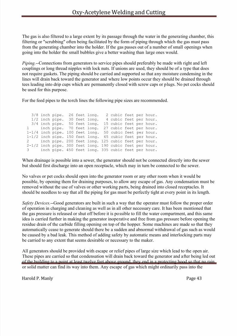
7/30/2019 Oxy Acetylene Welding and Cutting
http://slidepdf.com/reader/full/oxy-acetylene-welding-and-cutting 43/106
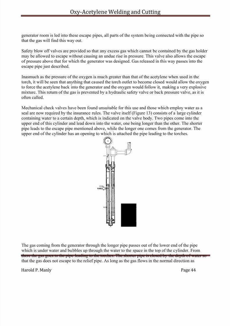
7/30/2019 Oxy Acetylene Welding and Cutting
http://slidepdf.com/reader/full/oxy-acetylene-welding-and-cutting 44/106
Oxy-Acetylene Welding and Cutting
Harold P. Manly Page 44
generator room is led into these escape pipes, all parts of the system being connected with the pipe sothat the gas will find this way out.
Safety blow off valves are provided so that any excess gas which cannot be contained by the gas holder
may be allowed to escape without causing an undue rise in pressure. This valve also allows the escapeof pressure above that for which the generator was designed. Gas released in this way passes into theescape pipe just described.
Inasmuch as the pressure of the oxygen is much greater than that of the acetylene when used in thetorch, it will be seen that anything that caused the torch outlet to become closed would allow the oxygento force the acetylene back into the generator and the oxygen would follow it, making a very explosivemixture. This return of the gas is prevented by a hydraulic safety valve or back pressure valve, as it isoften called.
Mechanical check valves have been found unsuitable for this use and those which employ water as a
seal are now required by the insurance rules. The valve itself (Figure 13) consists of a large cylinder containing water to a certain depth, which is indicated on the valve body. Two pipes come into theupper end of this cylinder and lead down into the water, one being longer than the other. The shorter pipe leads to the escape pipe mentioned above, while the longer one comes from the generator. Theupper end of the cylinder has an opening to which is attached the pipe leading to the torches.
The gas coming from the generator through the longer pipe passes out of the lower end of the pipewhich is under water and bubbles up through the water to the space in the top of the cylinder. Fromthere the gas goes to the pipe leading to the torches. The shorter pipe is closed by the depth of water sothat the gas does not escape to the relief pipe. As long as the gas flows in the normal direction as
7/30/2019 Oxy Acetylene Welding and Cutting
http://slidepdf.com/reader/full/oxy-acetylene-welding-and-cutting 45/106
Oxy-Acetylene Welding and Cutting
Harold P. Manly Page 45
described there will be no escape to the air. Should the gas in the torch line return into the hydraulicvalve its pressure will lower the level of water in the cylinder by forcing some of the liquid up into thetwo pipes. As the level of the water lowers, the shorter pipe will be uncovered first, and as this is the pipe leading to the open air the gas will be allowed to escape, while the pipe leading back to the
generator is still closed by the water seal. As soon as this reverse flow ceases, the water will againresume its level and the action will continue. Because of the small amount of water blown out of theescape pipe each time the valve is called upon to perform this duty, it is necessary to see that the correctwater level is always maintained.
While there are modifications of this construction, the same principle is used in all types. The pressureescape valve is often attached to this hydraulic valve body.
Construction Details.--Flexible tubing (except at torches), swing pipe joints, springs, mechanical check valves, chains, pulleys and lead or fusible piping should never be used on acetylene apparatus exceptwhere the failure of those parts will not affect the safety of the machine or permit, either directly or
indirectly, the escape of gas into a room. Floats should not be used except where failure will only render the machine inoperative.
It should be said that the National Board of Fire Underwriters have established an inspection service for acetylene generators and any apparatus which bears their label, stating that that particular model andtype has been passed, is safe to use. This service is for the best interests of all concerned and lookstoward the prevention of accidents. Such inspection is a very important and desirable feature of anyoutfit and should be insisted upon.
Location of Generators.--Generators should preferably be placed outside of insured buildings and in properly constructed generator houses. The operating mechanism should have ample room to work in
and there should be room enough for the attendant to reach the various parts and perform the requiredduties without hindrance or the need of artificial light. They should also be protected from tampering byunauthorized persons.
Generator houses should not be within five feet of any opening into, nor have any opening toward, anyadjacent building, and should be kept under lock and key. The size of the house should be no greater than called for by the requirements mentioned above and it should be well ventilated.
The foundation for the generator itself should be of brick, stone, concrete or iron, if possible. If of wood,they should be extra heavy, located in a dry place and open to circulation of air. A board platform is notsatisfactory, but the foundation should be of heavy planking or timber to make a firm base and so that
the air can circulate around the wood.
The generator should stand level and no strain should be placed on any of the pipes or connections or any parts of the generator proper.

7/30/2019 Oxy Acetylene Welding and Cutting
http://slidepdf.com/reader/full/oxy-acetylene-welding-and-cutting 46/106
Oxy-Acetylene Welding and Cutting
Harold P. Manly Page 46
CHAPTER IV
WELDING INSTRUMENTS
VALVES
Tank Valves.--The acetylene tank valve is of the needle type, fitted with suitable stuffing box nuts andending in an exposed square shank to which the special wrench may be fitted when the valve is to beopened or closed.
The valve used on Linde oxygen cylinders is also a needle type, but of slightly more complexconstruction. The body of the valve, which screws into the top of the cylinder, has an opening belowthrough which the gas comes from the cylinder, and another opening on the side through which it issuesto the torch line. A needle screws down from above to close this lower opening. The needle whichcloses the valve is not connected directly to the threaded member, but fits loosely into it. The threaded part is turned by a small hand wheel attached to the upper end. When this hand wheel is turned to theleft, or up, as far as it will go, opening the valve, a rubber disc is compressed inside of the valve bodyand this disc serves to prevent leakage of the gas around the spindle.
The oxygen valve also includes a safety nut having a small hole through it closed by a fusible metalwhich melts at 250° Fahrenheit. Melting of this plug allows the gas to exert its pressure against a thincopper diaphragm, this diaphragm bursting under the gas pressure and allowing the oxygen to escapeinto the air.
The hand wheel and upper end of the valve mechanism are protected during shipment by a large steelcap which covers them when screwed on to the end of the cylinder. This cap should always be in placewhen tanks are received from the makers or returned to them.
Regulating Valves.--While the pressure in the gas containers may be anything from zero to 1,800 pounds, and will vary as the gas is withdrawn, the pressure of the gas admitted to the torch must be heldsteady and at a definite point. This is accomplished by various forms of automatic regulating valves,which, while they differ somewhat in details of construction, all operate on the same principle.
The regulator body (Figure 14) carries a union which attaches to the side outlet on the oxygen tank valve. The gas passes through this union, following an opening which leads to a large gauge whichregisters the pressure on the oxygen remaining in the tank and also to a very small opening in the end of a tube. The gas passes through this opening and into the interior of the regulator body. Inside of the

7/30/2019 Oxy Acetylene Welding and Cutting
http://slidepdf.com/reader/full/oxy-acetylene-welding-and-cutting 47/106
Oxy-Acetylene Welding and Cutting
Harold P. Manly Page 47
body is a metal or rubber diaphragm placed so that the pressure of the incoming gas causes it to bulgeslightly. Attached to the diaphragm is a sleeve or an arm tipped with a small piece of fibre, the fibre being placed so that it is directly opposite the small hole through which the gas entered the diaphragmchamber. The slight movement of the diaphragm draws the fibre tightly over the small opening through
which the gas is entering, with the result that further flow is prevented.
Against the opposite side of the diaphragm is the end of a plunger. This plunger is pressed against thediaphragm by a coiled spring. The tension on the coiled spring is controlled by the operator through athreaded spindle ending in a wing or milled nut on the outside of the regulator body. Screwing in on thenut causes the tension on the spring to increase, with a consequent increase of pressure on the side of thediaphragm opposite to that on which the gas acts. Inasmuch as the gas pressure acted to close the smallgas opening and the spring pressure acts in the opposite direction from the gas, it will be seen that thespring pressure tends to keep the valve open.
When the nut is turned way out there is of course, no pressure on the spring side of the diaphragm and
the first gas coming through automatically closes the opening through which it entered. If now thetension on the spring be slightly increased, the valve will again open and admit gas until the pressure of gas within the regulator is just sufficient to overcome the spring pressure and again close the opening.There will then be a pressure of gas within the regulator that corresponds to the pressure placed on thespring by the operator. An opening leads from the regulator interior to the torch lines so that all gasgoing to the torches is drawn from the diaphragm chamber.
Any withdrawal of gas will, of course, lower the pressure of that remaining inside the regulator. Thespring tension, remaining at the point determined by the operator, will overcome this lessened pressureof the gas, and the valve will again open and admit enough more gas to bring the pressure back to thestarting point. This action continues as long as the spring tension remains at this point and as long as
any gas is taken from the regulator. Increasing the spring tension will require a greater gas pressure toclose the valve and the pressure of that in the regulator will be correspondingly higher.
When the regulator is not being used, the hand nut should be unscrewed until no tension remains on thespring, thus closing the valve. After the oxygen tank valve is open, the regulator hand nut is slowlyscrewed in until the spring tension is sufficient to give the required pressure in the torch lines. Another gauge is attached to the regulator so that it communicates with the interior of the diaphragm chamber,this gauge showing the gas pressure going to the torch. It is customary to incorporate a safety valve inthe regulator which will blow off at a dangerous pressure.
In regulating valves and tank valves, as well as all other parts with which the oxygen comes in contact,
it is not permissible to use any form of oil or grease because of danger of ignition and explosion. Themechanism of a regulator is too delicate to be handled in the ordinary shop and should any trouble or leakage develop in this part of the equipment it should be sent to a company familiar with this class of work for the necessary repairs. Gas must never be admitted to a regulator until the hand nut is all theway out, because of danger to the regulator itself and to the operator as well. A regulator can only be properly adjusted when the tank valve and torch valves are fully opened.
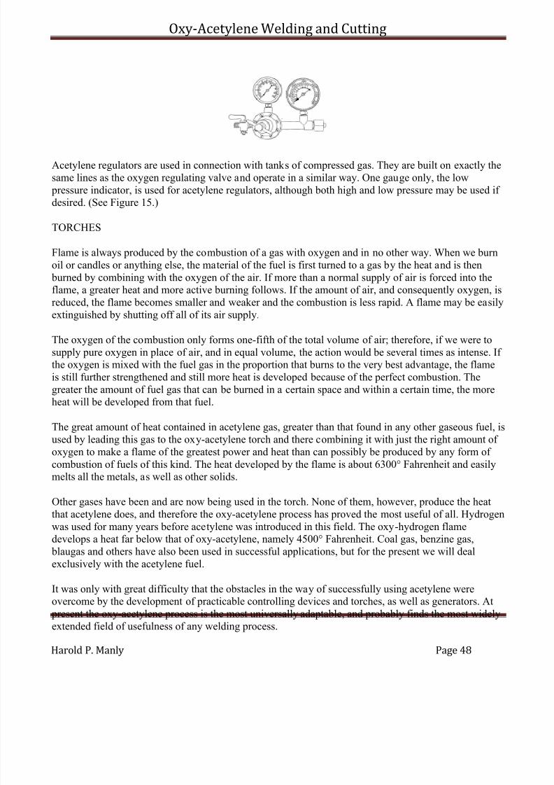
7/30/2019 Oxy Acetylene Welding and Cutting
http://slidepdf.com/reader/full/oxy-acetylene-welding-and-cutting 48/106
Oxy-Acetylene Welding and Cutting
Harold P. Manly Page 48
Acetylene regulators are used in connection with tanks of compressed gas. They are built on exactly thesame lines as the oxygen regulating valve and operate in a similar way. One gauge only, the low pressure indicator, is used for acetylene regulators, although both high and low pressure may be used if desired. (See Figure 15.)
TORCHES
Flame is always produced by the combustion of a gas with oxygen and in no other way. When we burnoil or candles or anything else, the material of the fuel is first turned to a gas by the heat and is then
burned by combining with the oxygen of the air. If more than a normal supply of air is forced into theflame, a greater heat and more active burning follows. If the amount of air, and consequently oxygen, isreduced, the flame becomes smaller and weaker and the combustion is less rapid. A flame may be easilyextinguished by shutting off all of its air supply.
The oxygen of the combustion only forms one-fifth of the total volume of air; therefore, if we were tosupply pure oxygen in place of air, and in equal volume, the action would be several times as intense. If the oxygen is mixed with the fuel gas in the proportion that burns to the very best advantage, the flameis still further strengthened and still more heat is developed because of the perfect combustion. Thegreater the amount of fuel gas that can be burned in a certain space and within a certain time, the moreheat will be developed from that fuel.
The great amount of heat contained in acetylene gas, greater than that found in any other gaseous fuel, isused by leading this gas to the oxy-acetylene torch and there combining it with just the right amount of oxygen to make a flame of the greatest power and heat than can possibly be produced by any form of combustion of fuels of this kind. The heat developed by the flame is about 6300° Fahrenheit and easilymelts all the metals, as well as other solids.
Other gases have been and are now being used in the torch. None of them, however, produce the heatthat acetylene does, and therefore the oxy-acetylene process has proved the most useful of all. Hydrogenwas used for many years before acetylene was introduced in this field. The oxy-hydrogen flamedevelops a heat far below that of oxy-acetylene, namely 4500° Fahrenheit. Coal gas, benzine gas,
blaugas and others have also been used in successful applications, but for the present we will dealexclusively with the acetylene fuel.
It was only with great difficulty that the obstacles in the way of successfully using acetylene wereovercome by the development of practicable controlling devices and torches, as well as generators. At present the oxy-acetylene process is the most universally adaptable, and probably finds the most widelyextended field of usefulness of any welding process.

7/30/2019 Oxy Acetylene Welding and Cutting
http://slidepdf.com/reader/full/oxy-acetylene-welding-and-cutting 49/106
Oxy-Acetylene Welding and Cutting
Harold P. Manly Page 49
The theoretical proportion of the gases for perfect combustion is two and one-half volumes of oxygen toone of acetylene. In practice this proportion is one and one-eighth or one and one-quarter volumes of oxygen to one volume of acetylene, so that the cost is considerably reduced below what it would be if the theoretical quantity were really necessary, as oxygen costs much more than acetylene in all cases.
While the heat is so intense as to fuse anything brought into the path of the flame, it is localized in thesmall "welding cone" at the torch tip so that the torch is not at all difficult to handle without special protection except for the eyes, as already noted. The art of successful welding may be acquired by anyoperator of average intelligence within a reasonable time and with some practice. One trouble met within the adoption of this process has been that the operation looks so simple and so easy of performancethat unskilled and unprepared persons have been tempted to try welding, with results that often causedcondemnation of the process, when the real fault lay entirely with the operator.
The form of torch usually employed is from twelve to twenty-four inches long and is composed of ahandle at one end with tubes leading from this handle to the "welding head" or torch proper. At or near
one end of the handle are adjustable cocks or valves for allowing the gases to flow into the torch or to prevent them from doing so. These cocks are often used for regulating the pressure and amount of gasflowing to the welding head, but are not always constructed for this purpose and should not be so usedwhen it is possible to secure pressure adjustment at the regulators (Figure 16).
Figure 16 shows three different sizes of torches. The number 5 torch is designed especially for jewelers'work and thin sheet steel welding. It is eleven inches in length and weighs nineteen ounces. The tips for the number 10 torch are interchangeable with the number 5. The number 10 torch is adapted for generaluse on light and medium heavy work. It has six tips and its length is sixteen inches, with a weight of twenty-three ounces.
The number 15 torch is designed for heavy work, being twenty-five inches in length, permitting theoperator to stand away from the heat of the metal being worked. These heavy tips are in two parts, theoxygen check being renewable.
Figures 17 and 18 show two sizes of another welding torch. Still another type is shown in Figure 19with four interchangeable tips, the function of each being as follows:
No. 1. For heavy castings.
No. 2. Light castings and heavy sheet metal.
No. 3. Light sheet metal.
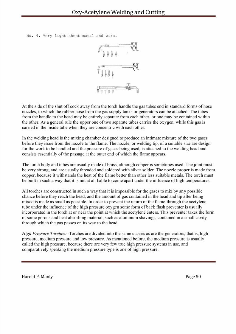
7/30/2019 Oxy Acetylene Welding and Cutting
http://slidepdf.com/reader/full/oxy-acetylene-welding-and-cutting 50/106
Oxy-Acetylene Welding and Cutting
Harold P. Manly Page 50
No. 4. Very light sheet metal and wire.
At the side of the shut off cock away from the torch handle the gas tubes end in standard forms of hosenozzles, to which the rubber hose from the gas supply tanks or generators can be attached. The tubes
from the handle to the head may be entirely separate from each other, or one may be contained withinthe other. As a general rule the upper one of two separate tubes carries the oxygen, while this gas iscarried in the inside tube when they are concentric with each other.
In the welding head is the mixing chamber designed to produce an intimate mixture of the two gases before they issue from the nozzle to the flame. The nozzle, or welding tip, of a suitable size are designfor the work to be handled and the pressure of gases being used, is attached to the welding head andconsists essentially of the passage at the outer end of which the flame appears.
The torch body and tubes are usually made of brass, although copper is sometimes used. The joint must be very strong, and are usually threaded and soldered with silver solder. The nozzle proper is made from
copper, because it withstands the heat of the flame better than other less suitable metals. The torch must be built in such a way that it is not at all liable to come apart under the influence of high temperatures.
All torches are constructed in such a way that it is impossible for the gases to mix by any possiblechance before they reach the head, and the amount of gas contained in the head and tip after beingmixed is made as small as possible. In order to prevent the return of the flame through the acetylenetube under the influence of the high pressure oxygen some form of back flash preventer is usuallyincorporated in the torch at or near the point at which the acetylene enters. This preventer takes the formof some porous and heat absorbing material, such as aluminum shavings, contained in a small cavitythrough which the gas passes on its way to the head.
High Pressure Torches.--Torches are divided into the same classes as are the generators; that is, high pressure, medium pressure and low pressure. As mentioned before, the medium pressure is usuallycalled the high pressure, because there are very few true high pressure systems in use, andcomparatively speaking the medium pressure type is one of high pressure.
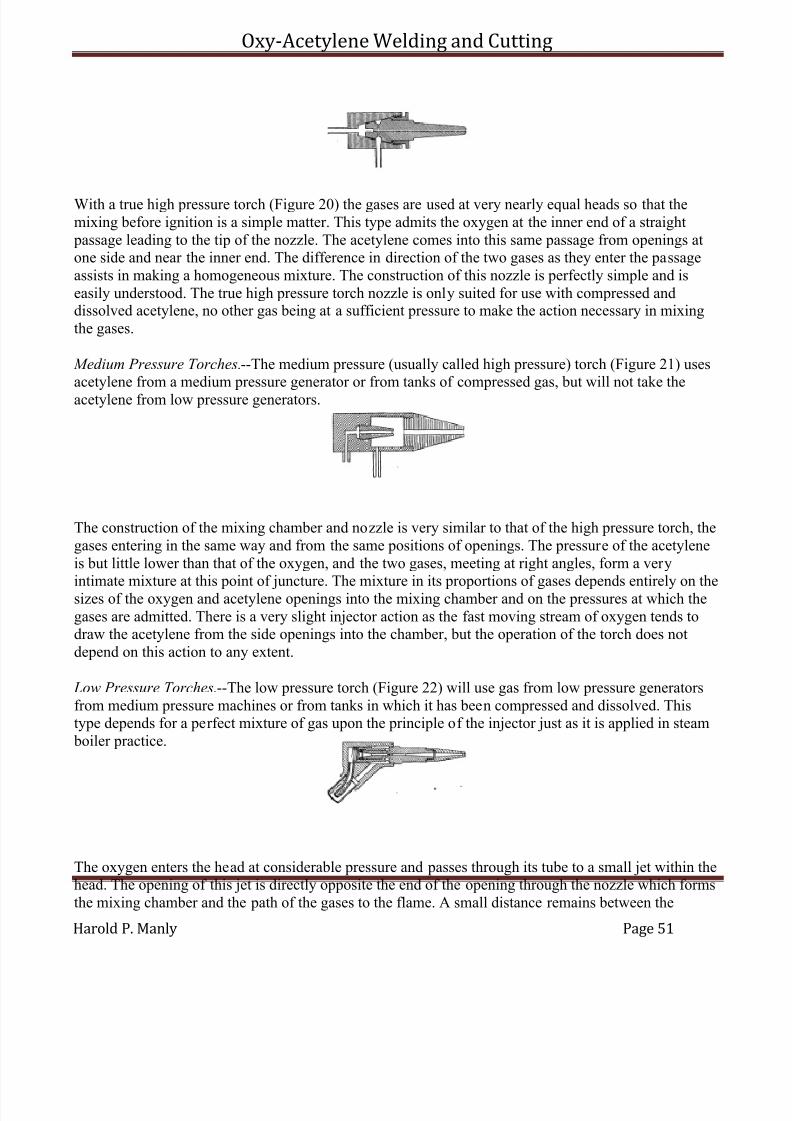
7/30/2019 Oxy Acetylene Welding and Cutting
http://slidepdf.com/reader/full/oxy-acetylene-welding-and-cutting 51/106
Oxy-Acetylene Welding and Cutting
Harold P. Manly Page 51
With a true high pressure torch (Figure 20) the gases are used at very nearly equal heads so that themixing before ignition is a simple matter. This type admits the oxygen at the inner end of a straight passage leading to the tip of the nozzle. The acetylene comes into this same passage from openings atone side and near the inner end. The difference in direction of the two gases as they enter the passageassists in making a homogeneous mixture. The construction of this nozzle is perfectly simple and iseasily understood. The true high pressure torch nozzle is only suited for use with compressed anddissolved acetylene, no other gas being at a sufficient pressure to make the action necessary in mixingthe gases.
Medium Pressure Torches.--The medium pressure (usually called high pressure) torch (Figure 21) usesacetylene from a medium pressure generator or from tanks of compressed gas, but will not take theacetylene from low pressure generators.
The construction of the mixing chamber and nozzle is very similar to that of the high pressure torch, thegases entering in the same way and from the same positions of openings. The pressure of the acetyleneis but little lower than that of the oxygen, and the two gases, meeting at right angles, form a veryintimate mixture at this point of juncture. The mixture in its proportions of gases depends entirely on thesizes of the oxygen and acetylene openings into the mixing chamber and on the pressures at which thegases are admitted. There is a very slight injector action as the fast moving stream of oxygen tends todraw the acetylene from the side openings into the chamber, but the operation of the torch does notdepend on this action to any extent.
Low Pressure Torches.--The low pressure torch (Figure 22) will use gas from low pressure generatorsfrom medium pressure machines or from tanks in which it has been compressed and dissolved. Thistype depends for a perfect mixture of gas upon the principle of the injector just as it is applied in steam boiler practice.
The oxygen enters the head at considerable pressure and passes through its tube to a small jet within thehead. The opening of this jet is directly opposite the end of the opening through the nozzle which formsthe mixing chamber and the path of the gases to the flame. A small distance remains between the
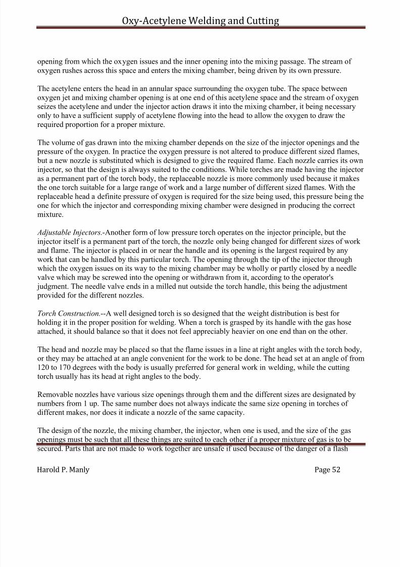
7/30/2019 Oxy Acetylene Welding and Cutting
http://slidepdf.com/reader/full/oxy-acetylene-welding-and-cutting 52/106
Oxy-Acetylene Welding and Cutting
Harold P. Manly Page 52
opening from which the oxygen issues and the inner opening into the mixing passage. The stream of oxygen rushes across this space and enters the mixing chamber, being driven by its own pressure.
The acetylene enters the head in an annular space surrounding the oxygen tube. The space between
oxygen jet and mixing chamber opening is at one end of this acetylene space and the stream of oxygenseizes the acetylene and under the injector action draws it into the mixing chamber, it being necessaryonly to have a sufficient supply of acetylene flowing into the head to allow the oxygen to draw therequired proportion for a proper mixture.
The volume of gas drawn into the mixing chamber depends on the size of the injector openings and the pressure of the oxygen. In practice the oxygen pressure is not altered to produce different sized flames, but a new nozzle is substituted which is designed to give the required flame. Each nozzle carries its owninjector, so that the design is always suited to the conditions. While torches are made having the injector as a permanent part of the torch body, the replaceable nozzle is more commonly used because it makesthe one torch suitable for a large range of work and a large number of different sized flames. With the
replaceable head a definite pressure of oxygen is required for the size being used, this pressure being theone for which the injector and corresponding mixing chamber were designed in producing the correctmixture.
Adjustable Injectors.-Another form of low pressure torch operates on the injector principle, but theinjector itself is a permanent part of the torch, the nozzle only being changed for different sizes of work and flame. The injector is placed in or near the handle and its opening is the largest required by anywork that can be handled by this particular torch. The opening through the tip of the injector throughwhich the oxygen issues on its way to the mixing chamber may be wholly or partly closed by a needlevalve which may be screwed into the opening or withdrawn from it, according to the operator's judgment. The needle valve ends in a milled nut outside the torch handle, this being the adjustment
provided for the different nozzles.
Torch Construction.--A well designed torch is so designed that the weight distribution is best for holding it in the proper position for welding. When a torch is grasped by its handle with the gas hoseattached, it should balance so that it does not feel appreciably heavier on one end than on the other.
The head and nozzle may be placed so that the flame issues in a line at right angles with the torch body,or they may be attached at an angle convenient for the work to be done. The head set at an angle of from120 to 170 degrees with the body is usually preferred for general work in welding, while the cuttingtorch usually has its head at right angles to the body.
Removable nozzles have various size openings through them and the different sizes are designated bynumbers from 1 up. The same number does not always indicate the same size opening in torches of different makes, nor does it indicate a nozzle of the same capacity.
The design of the nozzle, the mixing chamber, the injector, when one is used, and the size of the gasopenings must be such that all these things are suited to each other if a proper mixture of gas is to besecured. Parts that are not made to work together are unsafe if used because of the danger of a flash
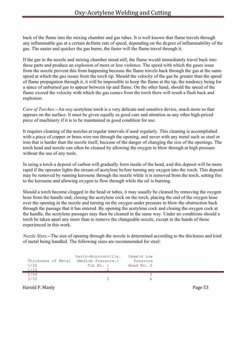
7/30/2019 Oxy Acetylene Welding and Cutting
http://slidepdf.com/reader/full/oxy-acetylene-welding-and-cutting 53/106
Oxy-Acetylene Welding and Cutting
Harold P. Manly Page 53
back of the flame into the mixing chamber and gas tubes. It is well known that flame travels throughany inflammable gas at a certain definite rate of speed, depending on the degree of inflammability of thegas. The easier and quicker the gas burns, the faster will the flame travel through it.
If the gas in the nozzle and mixing chamber stood still, the flame would immediately travel back intothese parts and produce an explosion of more or less violence. The speed with which the gases issuefrom the nozzle prevent this from happening because the flame travels back through the gas at the samespeed at which the gas issues from the torch tip. Should the velocity of the gas be greater than the speedof flame propagation through it, it will be impossible to keep the flame at the tip, the tendency being for a space of unburned gas to appear between tip and flame. On the other hand, should the speed of theflame exceed the velocity with which the gas comes from the torch there will result a flash back andexplosion.
Care of Torches.--An oxy-acetylene torch is a very delicate and sensitive device, much more so thatappears on the surface. It must be given equally as good care and attention as any other high-priced
piece of machinery if it is to be maintained in good condition for use.
It requires cleaning of the nozzles at regular intervals if used regularly. This cleaning is accomplishedwith a piece of copper or brass wire run through the opening, and never with any metal such as steel or iron that is harder than the nozzle itself, because of the danger of changing the size of the openings. Thetorch head and nozzle can often be cleaned by allowing the oxygen to blow through at high pressurewithout the use of any tools.
In using a torch a deposit of carbon will gradually form inside of the head, and this deposit will be morerapid if the operator lights the stream of acetylene before turning any oxygen into the torch. This depositmay be removed by running kerosene through the nozzle while it is removed from the torch, setting fire
to the kerosene and allowing oxygen to flow through while the oil is burning.
Should a torch become clogged in the head or tubes, it may usually be cleaned by removing the oxygenhose from the handle end, closing the acetylene cock on the torch, placing the end of the oxygen hoseover the opening in the nozzle and turning on the oxygen under pressure to blow the obstruction back through the passage that it has entered. By opening the acetylene cock and closing the oxygen cock atthe handle, the acetylene passages may then be cleaned in the same way. Under no conditions should atorch be taken apart any more than to remove the changeable nozzle, except in the hands of thoseexperienced in this work.
Nozzle Sizes.--The size of opening through the nozzle is determined according to the thickness and kind
of metal being handled. The following sizes are recommended for steel:
Davis-Bournonville. Oxweld LowThickness of Metal (Medium Pressure.) Pressure1/32 Tip No. 1 Head No. 21/16 25/64 33/32 3 4
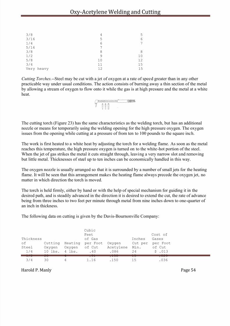
7/30/2019 Oxy Acetylene Welding and Cutting
http://slidepdf.com/reader/full/oxy-acetylene-welding-and-cutting 54/106
Oxy-Acetylene Welding and Cutting
Harold P. Manly Page 54
3/8 4 53/16 5 6
1/4 6 75/16 73/8 8 8
1/2 9 105/8 10 123/4 11 15Very heavy 12 15
Cutting Torches.--Steel may be cut with a jet of oxygen at a rate of speed greater than in any other practicable way under usual conditions. The action consists of burning away a thin section of the metal by allowing a stream of oxygen to flow onto it while the gas is at high pressure and the metal at a whiteheat.
The cutting torch (Figure 23) has the same characteristics as the welding torch, but has an additionalnozzle or means for temporarily using the welding opening for the high pressure oxygen. The oxygenissues from the opening while cutting at a pressure of from ten to 100 pounds to the square inch.
The work is first heated to a white heat by adjusting the torch for a welding flame. As soon as the metalreaches this temperature, the high pressure oxygen is turned on to the white-hot portion of the steel.When the jet of gas strikes the metal it cuts straight through, leaving a very narrow slot and removing but little metal. Thicknesses of steel up to ten inches can be economically handled in this way.
The oxygen nozzle is usually arranged so that it is surrounded by a number of small jets for the heatingflame. It will be seen that this arrangement makes the heating flame always precede the oxygen jet, nomatter in which direction the torch is moved.
The torch is held firmly, either by hand or with the help of special mechanism for guiding it in thedesired path, and is steadily advanced in the direction it is desired to extend the cut, the rate of advance being from three inches to two feet per minute through metal from nine inches down to one-quarter of an inch in thickness.
The following data on cutting is given by the Davis-Bournonville Company:
CubicFeet Cost of
Thickness of Gas Inches Gasesof Cutting Heating per Foot Oxygen Cut per per FootSteel Oxygen Oxygen of Cut Acetylene Min. of Cut1/4 10 lbs. 4 lbs. .40 .086 24 $ .0131/2 20 4 .91 .150 15 .0293/4 30 4 1.16 .150 15 .036
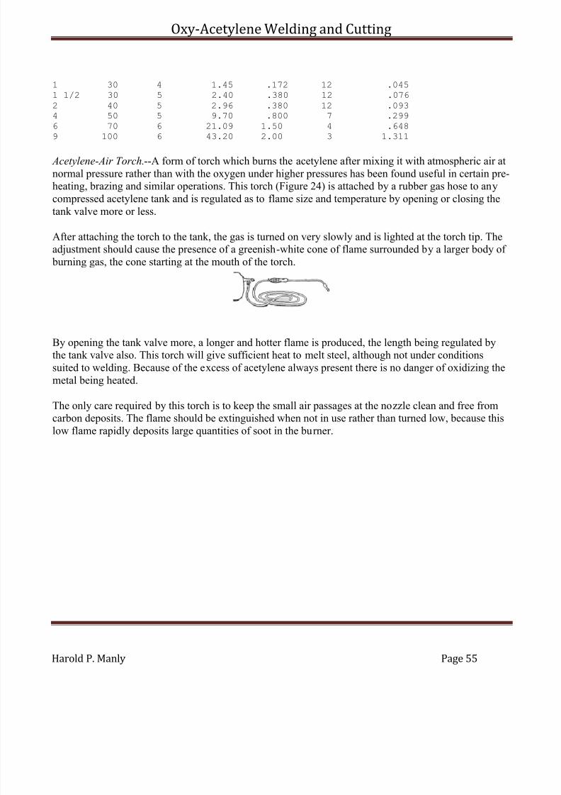
7/30/2019 Oxy Acetylene Welding and Cutting
http://slidepdf.com/reader/full/oxy-acetylene-welding-and-cutting 55/106
Oxy-Acetylene Welding and Cutting
Harold P. Manly Page 55
1 30 4 1.45 .172 12 .0451 1/2 30 5 2.40 .380 12 .076
2 40 5 2.96 .380 12 .0934 50 5 9.70 .800 7 .2996 70 6 21.09 1.50 4 .648
9 100 6 43.20 2.00 3 1.311
Acetylene-Air Torch.--A form of torch which burns the acetylene after mixing it with atmospheric air atnormal pressure rather than with the oxygen under higher pressures has been found useful in certain pre-heating, brazing and similar operations. This torch (Figure 24) is attached by a rubber gas hose to anycompressed acetylene tank and is regulated as to flame size and temperature by opening or closing thetank valve more or less.
After attaching the torch to the tank, the gas is turned on very slowly and is lighted at the torch tip. Theadjustment should cause the presence of a greenish-white cone of flame surrounded by a larger body of burning gas, the cone starting at the mouth of the torch.
By opening the tank valve more, a longer and hotter flame is produced, the length being regulated bythe tank valve also. This torch will give sufficient heat to melt steel, although not under conditionssuited to welding. Because of the excess of acetylene always present there is no danger of oxidizing themetal being heated.
The only care required by this torch is to keep the small air passages at the nozzle clean and free from
carbon deposits. The flame should be extinguished when not in use rather than turned low, because thislow flame rapidly deposits large quantities of soot in the burner.
7/30/2019 Oxy Acetylene Welding and Cutting
http://slidepdf.com/reader/full/oxy-acetylene-welding-and-cutting 56/106
Oxy-Acetylene Welding and Cutting
Harold P. Manly Page 56
CHAPTER V
OXY-ACETYLENE WELDING PRACTICE
PREPARATION OF WORK
Preheating.--The practice of heating the metal around the weld before applying the torch flame is adesirable one for two reasons. First, it makes the whole process more economical; second, it avoids thedanger of breakage through expansion and contraction of the work as it is heated and as it cools.
When it is desired to join two surfaces by welding them, it is, of course, necessary to raise the metalfrom the temperature of the surrounding air to its melting point, involving an increase in temperature of from one thousand to nearly three thousand degrees. To obtain this entire increase of temperature withthe torch flame is very wasteful of fuel and of the operator's time. The total amount of heat necessary to
put into metal is increased by the conductivity of that metal because the heat applied at the weld iscarried to other parts of the piece being handled until the whole mass is considerably raised intemperature. To secure this widely distributed increase the various methods of preheating are adopted.
As to the second reason for preliminary heating. It is understood that the metal added to the joint ismolten at the time it flows into place. All the metals used in welding contract as they cool and occupy amuch smaller space than when molten. If additional metal is run between two adjoining surfaces whichare parts of a surrounding body of cool metal, this added metal will cool while the surfaces themselvesare held stationary in the position they originally occupied. The inevitable result is that the metal addedwill crack under the strain, or, if the weld is exceptionally strong, the main body of the work will he broken by the force of contraction. To overcome these difficulties is the second and most importantreason for preheating and also for slow cooling following the completion of the weld.
There are many ways of securing this preheating. The work may be brought to a red heat in the forge if it is cast iron or steel; it may he heated in special ovens built for the purpose; it may be placed in a bedof charcoal while suitably supported; it may be heated by gas or gasoline preheating torches, and withvery small work the outer flame of the welding torch automatically provides means to this end.
The temperature of the parts heated should be gradually raised in all cases, giving the entire mass of metal a chance to expand equally and to adjust itself to the strains imposed by the preheating. After theregion around the weld has been brought to a proper temperature the opening to be filled is exposed sothat the torch flame can reach it, while the remaining surfaces are still protected from cold air currentsand from cooling through natural radiation.
One of the commonest methods and one of the best for handling work of rather large size is to place the piece to be welded on a bed of fire brick and build a loose wall around it with other fire brick placed inrows, one on top of the other, with air spaces left between adjacent bricks in each row. The space between the brick retaining wall and the work is filled with charcoal, which is lighted from below. Thetop opening of the temporary oven is then covered with asbestos and the fire kept up until the work has been uniformly raised in temperature to the desired point.
7/30/2019 Oxy Acetylene Welding and Cutting
http://slidepdf.com/reader/full/oxy-acetylene-welding-and-cutting 57/106
Oxy-Acetylene Welding and Cutting
Harold P. Manly Page 57
When much work of the same general character and size is to be handled, a permanent oven may beconstructed of fire brick, leaving a large opening through the top and also through one side. Charcoalmay be used in this form of oven as with the temporary arrangement, or the heat may be secured fromany form of burner or torch giving a large volume of flame. In any method employing flame to do the
heating, the work itself must be protected from the direct blast of the fire. Baffles of brick or metalshould be placed between the mouth of the torch and the nearest surface of the work so that the flamewill be deflected to either side and around the piece being heated.
The heat should be applied to bring the point of welding to the highest temperature desired and, exceptin the smallest work, the heat should gradually shade off from this point to the other parts of the piece.In the case of cast iron and steel the temperature at the point to be welded should be great enough to produce a dull red heat. This will make the whole operation much easier, because there will be nosurrounding cool metal to reduce the temperature of the molten material from the welding rod below the point at which it will join the work. From this red heat the mass of metal should grow cooler as thedistance from the weld becomes greater, so that no great strain is placed upon any one part. With work
of a very irregular shape it is always best to heat the entire piece so that the strains will be so evenlydistributed that they can cause no distortion or breakage under any conditions.
The melting point of the work which is being preheated should be kept in mind and care exercised not toapproach it too closely. Special care is necessary with aluminum in this respect, because of its lowmelting temperature and the sudden weakening and flowing without warning. Workmen have carelesslyoverheated aluminum castings and, upon uncovering the piece to make the weld, have been astonishedto find that it had disappeared. Six hundred degrees is about the safe limit for this metal. It is possible togauge the exact temperature of the work with a pyrometer, but when this instrument cannot be procured,it might be well to secure a number of "temperature cones" from a chemical or laboratory supply house.These cones are made from material that will soften at a certain heat and in form they are long and
pointed. Placed in position on the part being heated, the point may be watched, and when it bends over it is sure that the metal itself has reached a temperature considerably in excess of the temperature atwhich that particular cone was designed to soften.
The object in preheating the metal around the weld is to cause it to expand sufficiently to open the crack a distance equal to the contraction when cooling from the melting point. In the case of a crack runningfrom the edge of a piece into the body or of a crack wholly within the body, it is usually satisfactory toheat the metal at each end of the opening. This will cause the whole length of the crack to opensufficiently to receive the molten material from the rod.
The judgment of the operator will be called upon to decide just where a piece of metal should be heated
to open the weld properly. It is often possible to apply the preheating flame to a point some distancefrom the point of work if the parts are so connected that the expansion of the heated part will serve todraw the edges of the weld apart. Whatever part of the work is heated to cause expansion andseparation, this part must remain hot during the entire time of welding and must then cool slowly at thesame time as the metal in the weld cools.
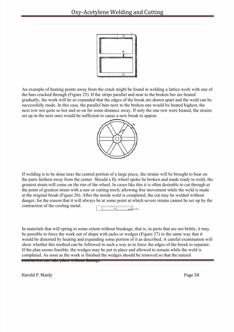
7/30/2019 Oxy Acetylene Welding and Cutting
http://slidepdf.com/reader/full/oxy-acetylene-welding-and-cutting 58/106
Oxy-Acetylene Welding and Cutting
Harold P. Manly Page 58
An example of heating points away from the crack might be found in welding a lattice work with one of the bars cracked through (Figure 25). If the strips parallel and near to the broken bar are heatedgradually, the work will be so expanded that the edges of the break are drawn apart and the weld can besuccessfully made. In this case, the parallel bars next to the broken one would be heated highest, thenext row not quite so hot and so on for some distance away. If only the one row were heated, the strains
set up in the next ones would be sufficient to cause a new break to appear.
If welding is to be done near the central portion of a large piece, the strains will be brought to bear onthe parts farthest away from the center. Should a fly wheel spoke be broken and made ready to weld, thegreatest strain will come on the rim of the wheel. In cases like this it is often desirable to cut through atthe point of greatest strain with a saw or cutting torch, allowing free movement while the weld is madeat the original break (Figure 26). After the inside weld is completed, the cut may be welded withoutdanger, for the reason that it will always be at some point at which severe strains cannot be set up by thecontraction of the cooling metal.
In materials that will spring to some extent without breakage, that is, in parts that are not brittle, it may
be possible to force the work out of shape with jacks or wedges (Figure 27) in the same way that itwould be distorted by heating and expanding some portion of it as described. A careful examination willshow whether this method can be followed in such a way as to force the edges of the break to separate.If the plan seems feasible, the wedges may be put in place and allowed to remain while the weld iscompleted. As soon as the work is finished the wedges should be removed so that the naturalcontraction can take place without damage.
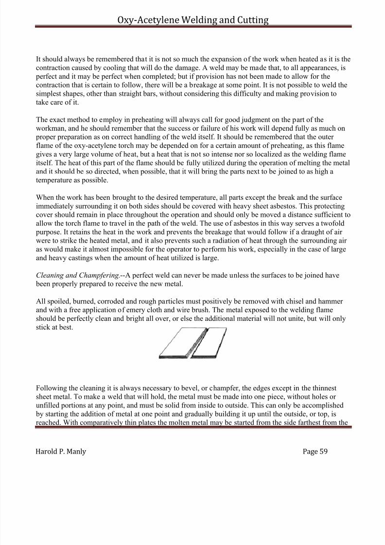
7/30/2019 Oxy Acetylene Welding and Cutting
http://slidepdf.com/reader/full/oxy-acetylene-welding-and-cutting 59/106
Oxy-Acetylene Welding and Cutting
Harold P. Manly Page 59
It should always be remembered that it is not so much the expansion of the work when heated as it is thecontraction caused by cooling that will do the damage. A weld may be made that, to all appearances, is perfect and it may be perfect when completed; but if provision has not been made to allow for thecontraction that is certain to follow, there will be a breakage at some point. It is not possible to weld the
simplest shapes, other than straight bars, without considering this difficulty and making provision totake care of it.
The exact method to employ in preheating will always call for good judgment on the part of theworkman, and he should remember that the success or failure of his work will depend fully as much on proper preparation as on correct handling of the weld itself. It should be remembered that the outer flame of the oxy-acetylene torch may be depended on for a certain amount of preheating, as this flamegives a very large volume of heat, but a heat that is not so intense nor so localized as the welding flameitself. The heat of this part of the flame should be fully utilized during the operation of melting the metaland it should be so directed, when possible, that it will bring the parts next to be joined to as high atemperature as possible.
When the work has been brought to the desired temperature, all parts except the break and the surfaceimmediately surrounding it on both sides should be covered with heavy sheet asbestos. This protectingcover should remain in place throughout the operation and should only be moved a distance sufficient toallow the torch flame to travel in the path of the weld. The use of asbestos in this way serves a twofold purpose. It retains the heat in the work and prevents the breakage that would follow if a draught of air were to strike the heated metal, and it also prevents such a radiation of heat through the surrounding air as would make it almost impossible for the operator to perform his work, especially in the case of largeand heavy castings when the amount of heat utilized is large.
Cleaning and Champfering.--A perfect weld can never be made unless the surfaces to be joined have
been properly prepared to receive the new metal.
All spoiled, burned, corroded and rough particles must positively be removed with chisel and hammer and with a free application of emery cloth and wire brush. The metal exposed to the welding flameshould be perfectly clean and bright all over, or else the additional material will not unite, but will onlystick at best.
Following the cleaning it is always necessary to bevel, or champfer, the edges except in the thinnestsheet metal. To make a weld that will hold, the metal must be made into one piece, without holes or unfilled portions at any point, and must be solid from inside to outside. This can only be accomplished by starting the addition of metal at one point and gradually building it up until the outside, or top, isreached. With comparatively thin plates the molten metal may be started from the side farthest from the

7/30/2019 Oxy Acetylene Welding and Cutting
http://slidepdf.com/reader/full/oxy-acetylene-welding-and-cutting 60/106
Oxy-Acetylene Welding and Cutting
Harold P. Manly Page 60
operator and brought through, but with thicker sections the addition is started in the middle and broughtflush with one side and then with the other.
It will readily be seen that the molten material cannot be depended upon to flow between the tightly
closed surfaces of a crack in a way that can be at all sure to make a true weld. It will be necessary for the operator to reach to the farthest side with the flame and welding rod, and to start the new surfacesthere. To allow this, the edges that are to be joined are beveled from one side to the other (Figure 28), sothat when placed together in approximately the position they are to occupy they will leave a groovedchannel between them with its sides at an angle with each other sufficient in size to allow access toevery point of each surface.
With work less than one-fourth inch thick, this angle should be forty-five degrees on each piece (Figure29), so that when they are placed together the extreme edges will meet at the bottom of a groove whosesides are square, or at right angles, to each other. This beveling should be done so that only a thin edgeis left where the two parts come together, just enough points in contact to make the alignment easy tohold. With work of a thickness greater than a quarter of an inch, the angle of bevel on each piece may besixty degrees (Figure 30), so that when placed together the angle included between the sloping sides willalso be sixty degrees. If the plate is less than one-eighth of an inch thick the beveling is not necessary,as the edges may be melted all the way through without danger of leaving blowholes at any point.
This beveling may be done in any convenient way. A chisel is usually most satisfactory and alsoquickest. Small sections may be handled by filing, while metal that is too hard to cut in either of theseways may be shaped on the emery wheel. It is not necessary that the edges be perfectly finished andabsolutely smooth, but they should be of regular outline and should always taper off to a thin edge sothat when the flame is first applied it can be seen issuing from the far side of the crack. If the work isquite thick and is of a shape that will allow it to be turned over, the bevel may be brought from both
sides (Figure 31), so that there will be two grooves, one on each surface of the work. After completingthe weld on one side, the piece is reversed and finished on the other side. Figure 32 shows the proper beveling for welding pipe. Figure 33 shows how sheet metal may be flanged for welding.
Welding should not be attempted with the edges separated in place of beveled, because it will be foundimpossible to build up a solid web of new metal from one side clear through to the other by this method.The flame cannot reach the surfaces to make them molten while receiving new material from the rod,
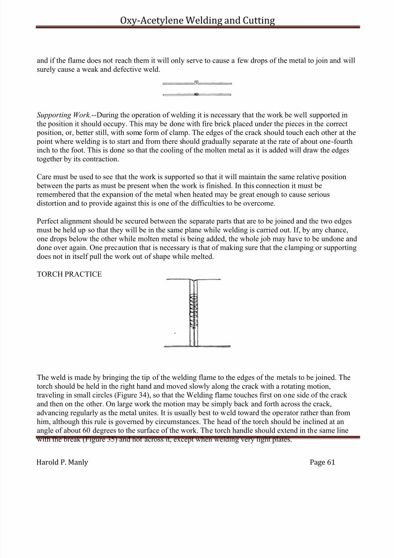
7/30/2019 Oxy Acetylene Welding and Cutting
http://slidepdf.com/reader/full/oxy-acetylene-welding-and-cutting 61/106
Oxy-Acetylene Welding and Cutting
Harold P. Manly Page 61
and if the flame does not reach them it will only serve to cause a few drops of the metal to join and willsurely cause a weak and defective weld.
Supporting Work.--During the operation of welding it is necessary that the work be well supported inthe position it should occupy. This may be done with fire brick placed under the pieces in the correct position, or, better still, with some form of clamp. The edges of the crack should touch each other at the point where welding is to start and from there should gradually separate at the rate of about one-fourthinch to the foot. This is done so that the cooling of the molten metal as it is added will draw the edgestogether by its contraction.
Care must be used to see that the work is supported so that it will maintain the same relative position between the parts as must be present when the work is finished. In this connection it must be
remembered that the expansion of the metal when heated may be great enough to cause seriousdistortion and to provide against this is one of the difficulties to be overcome.
Perfect alignment should be secured between the separate parts that are to be joined and the two edgesmust be held up so that they will be in the same plane while welding is carried out. If, by any chance,one drops below the other while molten metal is being added, the whole job may have to be undone anddone over again. One precaution that is necessary is that of making sure that the clamping or supportingdoes not in itself pull the work out of shape while melted.
TORCH PRACTICE
The weld is made by bringing the tip of the welding flame to the edges of the metals to be joined. Thetorch should be held in the right hand and moved slowly along the crack with a rotating motion,traveling in small circles (Figure 34), so that the Welding flame touches first on one side of the crack and then on the other. On large work the motion may be simply back and forth across the crack,advancing regularly as the metal unites. It is usually best to weld toward the operator rather than fromhim, although this rule is governed by circumstances. The head of the torch should be inclined at anangle of about 60 degrees to the surface of the work. The torch handle should extend in the same linewith the break (Figure 35) and not across it, except when welding very light plates.
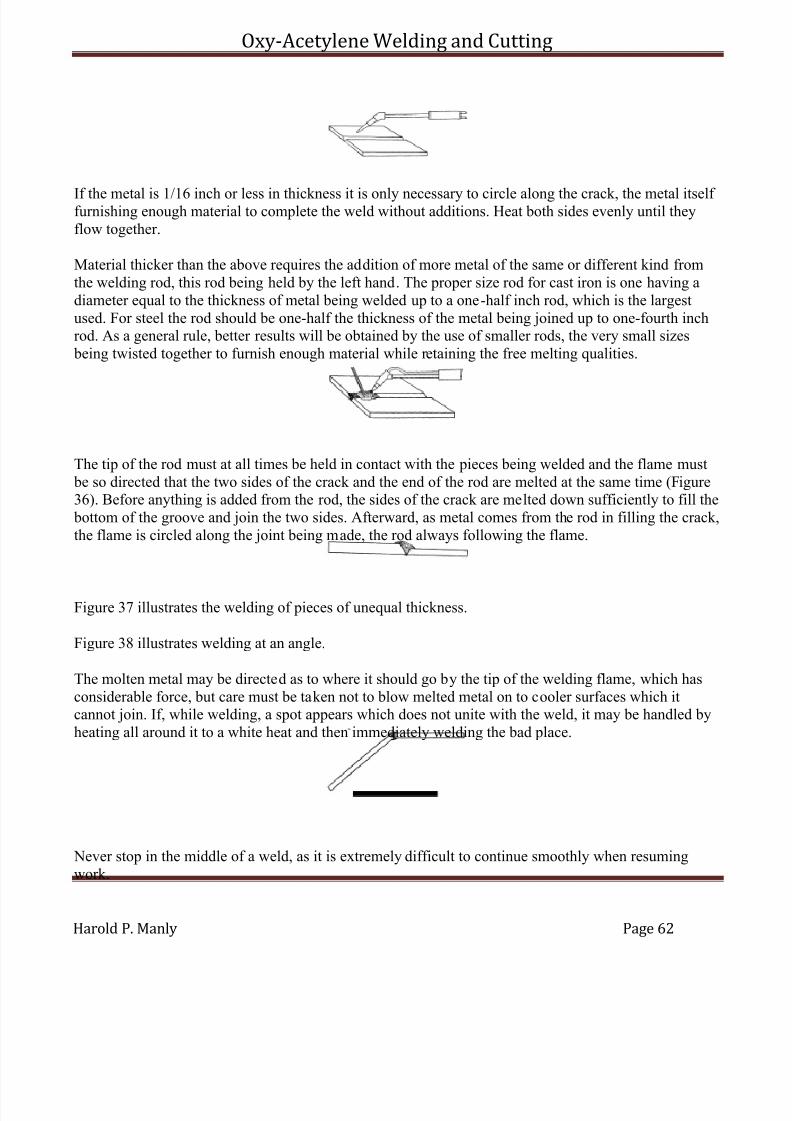
7/30/2019 Oxy Acetylene Welding and Cutting
http://slidepdf.com/reader/full/oxy-acetylene-welding-and-cutting 62/106
Oxy-Acetylene Welding and Cutting
Harold P. Manly Page 62
If the metal is 1/16 inch or less in thickness it is only necessary to circle along the crack, the metal itself furnishing enough material to complete the weld without additions. Heat both sides evenly until theyflow together.
Material thicker than the above requires the addition of more metal of the same or different kind fromthe welding rod, this rod being held by the left hand. The proper size rod for cast iron is one having adiameter equal to the thickness of metal being welded up to a one-half inch rod, which is the largestused. For steel the rod should be one-half the thickness of the metal being joined up to one-fourth inchrod. As a general rule, better results will be obtained by the use of smaller rods, the very small sizes being twisted together to furnish enough material while retaining the free melting qualities.
The tip of the rod must at all times be held in contact with the pieces being welded and the flame must be so directed that the two sides of the crack and the end of the rod are melted at the same time (Figure36). Before anything is added from the rod, the sides of the crack are melted down sufficiently to fill the bottom of the groove and join the two sides. Afterward, as metal comes from the rod in filling the crack,the flame is circled along the joint being made, the rod always following the flame.
Figure 37 illustrates the welding of pieces of unequal thickness.
Figure 38 illustrates welding at an angle.
The molten metal may be directed as to where it should go by the tip of the welding flame, which hasconsiderable force, but care must be taken not to blow melted metal on to cooler surfaces which itcannot join. If, while welding, a spot appears which does not unite with the weld, it may be handled byheating all around it to a white heat and then immediately welding the bad place.
Never stop in the middle of a weld, as it is extremely difficult to continue smoothly when resumingwork.
7/30/2019 Oxy Acetylene Welding and Cutting
http://slidepdf.com/reader/full/oxy-acetylene-welding-and-cutting 63/106
Oxy-Acetylene Welding and Cutting
Harold P. Manly Page 63
The Flame.--The welding flame must have exactly the right proportions of each gas. If there is too muchoxygen, the metal will be burned or oxidized; the presence of too much acetylene carbonizes the metal;that is to say, it adds carbon and makes the work harder. Just the right mixture will neither burn nor carbonize and is said to be a "neutral" flame. The neutral flame, if of the correct size for the work,
reduces the metal to a melted condition, not too fluid, and for a width about the same as the thickness of the metal being welded.
When ready to light the torch, after attaching the right tip or head as directed in accordance with thethickness of metal to be handled, it will be necessary to regulate the pressure of gases to secure theneutral flame.
The oxygen will have a pressure of from 2 to 20 pounds, according to the nozzle used. The acetylenewill have much less. Even with the compressed gas, the pressure should never exceed 10 pounds for thelargest work, and it will usually be from 4 to 6. In low pressure systems, the acetylene will be receivedat generator pressure. It should first be seen that the hand-screws on the regulators are turned way out so
that the springs are free from any tension. It will do no harm if these screws are turned back until theycome out of the threads. This must be done with both oxygen and acetylene regulators.
Next, open the valve from the generator, or on the acetylene tank, and carefully note whether there isany odor of escaping gas. Any leakage of this gas must be stopped before going on with the work.
The hand wheel controlling the oxygen cylinder valve should now be turned very slowly to the left asfar as it will go, which opens the valve, and it should be borne in mind the pressure that is beingreleased. Turn in the hand screw on the oxygen regulator until the small pressure gauge shows a readingaccording to the requirements of the nozzle being used. This oxygen regulator adjustment should bemade with the cock on the torch open, and after the regulator is thus adjusted the torch cock may be
closed.
Open the acetylene cock on the torch and screw in on the acetylene regulator hand-screw until gascommences to come through the torch. Light this flow of acetylene and adjust the regulator screw to the pressure desired, or, if there is no gauge, so that there is a good full flame. With the pressure of acetylene controlled by the type of generator it will only be necessary to open the torch cock.
With the acetylene burning, slowly open the oxygen cock on the torch and allow this gas to join theflame. The flame will turn intensely bright and then blue white. There will be an outer flame from four to eight inches long and from one to three inches thick. Inside of this flame will be two more rather distinctly defined flames. The inner one at the torch tip is very small, and the intermediate one is long
and pointed. The oxygen should be turned on until the two inner flames unite into one blue-white conefrom one-fourth to one-half inch long and one-eighth to one-fourth inch in diameter. If this single,clearly defined cone does not appear when the oxygen torch cock has been fully opened, turn off someof the acetylene until it does appear.
If too much oxygen is added to the flame, there will still be the central blue-white cone, but it will besmaller and more or less ragged around the edges (Figure 39). When there is just enough oxygen to
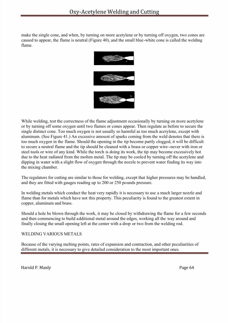
7/30/2019 Oxy Acetylene Welding and Cutting
http://slidepdf.com/reader/full/oxy-acetylene-welding-and-cutting 64/106
Oxy-Acetylene Welding and Cutting
Harold P. Manly Page 64
make the single cone, and when, by turning on more acetylene or by turning off oxygen, two cones arecaused to appear, the flame is neutral (Figure 40), and the small blue-white cone is called the weldingflame.
While welding, test the correctness of the flame adjustment occasionally by turning on more acetyleneor by turning off some oxygen until two flames or cones appear. Then regulate as before to secure thesingle distinct cone. Too much oxygen is not usually so harmful as too much acetylene, except withaluminum. (See Figure 41.) An excessive amount of sparks coming from the weld denotes that there istoo much oxygen in the flame. Should the opening in the tip become partly clogged, it will be difficultto secure a neutral flame and the tip should be cleaned with a brass or copper wire--never with iron or steel tools or wire of any kind. While the torch is doing its work, the tip may become excessively hotdue to the heat radiated from the molten metal. The tip may be cooled by turning off the acetylene anddipping in water with a slight flow of oxygen through the nozzle to prevent water finding its way intothe mixing chamber.
The regulators for cutting are similar to those for welding, except that higher pressures may be handled,and they are fitted with gauges reading up to 200 or 250 pounds pressure.
In welding metals which conduct the heat very rapidly it is necessary to use a much larger nozzle andflame than for metals which have not this property. This peculiarity is found to the greatest extent incopper, aluminum and brass.
Should a hole be blown through the work, it may be closed by withdrawing the flame for a few secondsand then commencing to build additional metal around the edges, working all the way around andfinally closing the small opening left at the center with a drop or two from the welding rod.
WELDING VARIOUS METALS
Because of the varying melting points, rates of expansion and contraction, and other peculiarities of different metals, it is necessary to give detailed consideration to the most important ones.
7/30/2019 Oxy Acetylene Welding and Cutting
http://slidepdf.com/reader/full/oxy-acetylene-welding-and-cutting 65/106
Oxy-Acetylene Welding and Cutting
Harold P. Manly Page 65
Characteristics of Metals.--The welder should thoroughly understand the peculiarities of the variousmetals with which he has to deal. The metals and their alloys are described under this heading in thefirst chapter of this book and a tabulated list of the most important points relating to each metal will befound at the end of the present chapter. All this information should be noted by the operator of a
welding installation before commencing actual work.
Because of the nature of welding, the melting point of a metal is of great importance. A metal melting ata low temperature should have more careful treatment to avoid undesired flow than one which melts at atemperature which is relatively high. When two dissimilar metals are to be joined, the one which meltsat the higher temperature must be acted upon by the flame first and when it is in a molten condition theheat contained in it will in many cases be sufficient to cause fusion of the lower melting metal and allowthem to unite without playing the flame on the lower metal to any great extent.
The heat conductivity bears a very important relation to welding, inasmuch as a metal with a high rateof conductance requires more protection from cooling air currents and heat radiation than one not
having this quality to such a marked extent. A metal which conducts heat rapidly will require a larger volume of flame, a larger nozzle, than otherwise, this being necessary to supply the additional heattaken away from the welding point by this conductance.
The relative rates of expansion of the various metals under heat should be understood in order that partsmade from such material may have proper preparation to compensate for this expansion and contraction.Parts made from metals having widely varying rates of expansion must have special treatment to allowfor this quality, otherwise breakage is sure to occur.
Cast Iron.--All spoiled metal should he cut away and if the work is more than one-eighth inch inthickness the sides of the crack should be beveled to a 45 degree angle, leaving a number of points
touching at the bottom of the bevel so that the work may be joined in its original relation.
The entire piece should be preheated in a bricked-up oven or with charcoal placed on the forge, whensize does not warrant building a temporary oven. The entire piece should be slowly heated and the portion immediately surrounding the weld should be brought to a dull red. Care should be used that theheat does not warp the metal through application to one part more than the others. After welding, thework should be slowly cooled by covering with ashes, slaked lime, asbestos fibre or some other non-conductor of heat. These precautions are absolutely essential in the case of cast iron.
A neutral flame, from a nozzle proportioned to the thickness of the work, should be held with the pointof the blue-white cone about one-eighth inch from the surface of the iron.
A cast iron rod of correct diameter, usually made with an excess of silicon, is used by keeping its end incontact with the molten metal and flowing it into the puddle formed at the point of fusion. Metal should be added so that the weld stands about one-eighth inch above the surrounding surface of the work.
Various forms of flux may be used and they are applied by dipping the end of the welding rod into the powder at intervals. These powders may contain borax or salt, and to prevent a hard, brittle weld,
7/30/2019 Oxy Acetylene Welding and Cutting
http://slidepdf.com/reader/full/oxy-acetylene-welding-and-cutting 66/106
Oxy-Acetylene Welding and Cutting
Harold P. Manly Page 66
graphite or ferro-silicon may be added. Flux should be added only after the iron is molten and as little as possible should be used. No flux should be used just before completion of the work.
The welding flame should be played on the work around the crack and gradually brought to bear on the
work. The bottom of the bevel should be joined first and it will be noted that the cast iron tends to runtoward the flame, but does not stick together easily. A hard and porous weld should be carefullyguarded against, as described above, and upon completion of the work the welded surface should bescraped with a file, while still red hot, in order to remove the surface scale.
Malleable Iron.--This material should be beveled in the same way that cast iron is handled, and preheating and slow cooling are equally desirable. The flame used is the same as for cast iron and so isthe flux. The welding rod may be of cast iron, although better results are secured with Norway iron wireor else a mild steel wire wrapped with a coil of copper wire.
It will be understood that malleable iron turns to ordinary cast iron when melted and cooled. Welds in
malleable iron are usually far from satisfactory and a better joint is secured by brazing the edgestogether with bronze. The edges to be joined are brought to a heat just a little below the point at whichthey will flow and the opening is then quickly-filled from a rod of Tobin bronze or manganese bronze, a brass or bronze flux being used in this work.
Wrought Iron or Semi-Steel.--This metal should be beveled and heated in the same way as described for cast iron. The flame should be neutral, of the same size as for steel, and used with the tip of the blue-white cone just touching the work. The welding rod should be of mild steel, or, if wrought iron is to bewelded to steel, a cast iron rod may be used. A cast iron flux is well suited for this work. It should benoted that wrought iron turns to ordinary cast iron if kept heated for any length of time.
Steel.--Steel should be beveled if more than one-eighth inch in thickness. It requires only a local preheating around the point to be welded. The welding flame should be absolutely neutral, withoutexcess of either gas. If the metal is one-sixteenth inch or less in thickness, the tip of the blue-white conemust be held a short distance from the surface of the work; in all other cases the tip of this cone istouched to the metal being welded.
The welding rod may be of mild, low carbon steel or of Norway iron. Nickel steel rods may be used for parts requiring great strength, but vanadium alloys are very difficult to handle. A very satisfactory rod ismade by twisting together two wires of the required material. The rod must be kept constantly in contactwith the work and should not be added until the edges are thoroughly melted. The flux may or may not be used. If one is wanted, it may be made from three parts iron filings, six parts borax and one part sal
ammoniac.
It will be noticed that the steel runs from the flame, but tends to hold together. Should foamingcommence in the molten metal, it shows an excess of oxygen and that the metal is being burned.
High carbon steels are very difficult to handle. It is claimed that a drop or two of copper added to theweld will assist the flow, but will also harden the work. An excess of oxygen reduces the amount of
7/30/2019 Oxy Acetylene Welding and Cutting
http://slidepdf.com/reader/full/oxy-acetylene-welding-and-cutting 67/106
Oxy-Acetylene Welding and Cutting
Harold P. Manly Page 67
carbon and softens the steel, while an excess of acetylene increases the proportion of carbon andhardens the metal. High speed steels may sometimes be welded if first coated with semi-steel beforewelding.
Aluminum.--This is the most difficult of the commonly found metals to weld. This is caused by its highrate of expansion and contraction and its liability to melt and fall away from under the flame. Thealuminum seems to melt on the inside first, and, without previous warning, a portion of the work willsimply vanish from in front of the operator's eyes. The metal tends to run from the flame and separate atthe same time. To keep the metal in shape and free from oxide, it is worked or puddled while in a plasticcondition by an iron rod which has been flattened at one end. Several of these rods should be at handand may be kept in a jar of salt water while not being used. These rods must not become coated withaluminum and they must not get red hot while in the weld.
The surfaces to be joined, together with the adjacent parts, should be cleaned thoroughly and thenwashed with a 25 per cent solution of nitric acid in hot water, used on a swab. The parts should then be
rinsed in clean water and dried with sawdust. It is also well to make temporary fire clay moulds back of the parts to be heated, so that the metal may be flowed into place and allowed to cool without danger of breakage.
Aluminum must invariably be preheated to about 600 degrees, and the whole piece being handledshould be well covered with sheet asbestos to prevent excessive heat radiation.
The flame is formed with an excess of acetylene such that the second cone extends about an inch, or slightly more, beyond the small blue-white point. The torch should be held so that the end of this secondcone is in contact with the work, the small cone ordinarily used being kept an inch or an inch and a half from the surface of the work.
Welding rods of special aluminum are used and must be handled with their end submerged in the moltenmetal of the weld at all times.
When aluminum is melted it forms alumina, an oxide of the metal. This alumina surrounds small massesof the metal, and as it does not melt at temperatures below 5000 degrees (while aluminum melts at about1200), it prevents a weld from being made. The formation of this oxide is retarded and the oxide itself isdissolved by a suitable flux, which usually contains phosphorus to break down the alumina.
Copper.--The whole piece should be preheated and kept well covered while welding. The flame must bemuch larger than for the same thickness of steel and neutral in character. A slight excess of acetylene
would be preferable to an excess of oxygen, and in all cases the molten metal should be kept envelopedwith the flame. The welding rod is of copper which contains phosphorus; and a flux, also containing phosphorus, should be spread for about an inch each side of the joint. These assist in preventingoxidation, which is sure to occur with heated copper.
Copper breaks very easily at a heat slightly under the welding temperature and after cooling it is simplycast copper in all cases.

7/30/2019 Oxy Acetylene Welding and Cutting
http://slidepdf.com/reader/full/oxy-acetylene-welding-and-cutting 68/106
Oxy-Acetylene Welding and Cutting
Harold P. Manly Page 68
Brass and Bronze.--It is necessary to preheat these metals, although not to a very high temperature.They must be kept well covered at all times to prevent undue radiation. The flame should be producedwith a nozzle one size larger than for the same thickness of steel and the small blue-white cone should be held from one-fourth to one-half inch above the surface of the work. The flame should be neutral in
character.
A rod or wire of soft brass containing a large percentage of zinc is suitable for adding to brass, whilecopper requires the use of copper or manganese bronze rods. Special flux or borax may be used to assistthe flow.
The emission of white smoke indicates that the zinc contained in these alloys is being burned away andthe heat should immediately be turned away or reduced. The fumes from brass and bronze welding arevery poisonous and should not be breathed.
RESTORATION OF STEEL
The result of the high heat to which the steel has been subjected is that it is weakened and of a differentcharacter than before welding. The operator may avoid this as much as possible by first playing theouter flame of the torch all over the surfaces of the work just completed until these faces are all of uniform color, after which the metal should be well covered with asbestos and allowed to cool without being disturbed. If a temporary heating oven has been employed, the work and oven should be allowedto cool together while protected with the sheet asbestos. If the outside air strikes the freshly weldedwork, even for a moment, the result will be breakage.
A weld in steel will always leave the metal with a coarse grain and with all the characteristics of rather low grade cast steel. As previously mentioned in another chapter, the larger the grain size in steel the
weaker the metal will be, and it is the purpose of the good workman to avoid, as far as possible, thisweakening.
The structure of the metal in one piece of steel will differ according to the heat that it has under gone.The parts of the work that have been at the melting point will, therefore, have the largest grain size andthe least strength. Those parts that have not suffered any great rise in temperature will be practicallyunaffected, and all the parts between these two extremes will be weaker or stronger according to their distance from the weld itself. To restore the steel so that it will have the best grain size, the operator may resort to either of two methods: (1) The grain may be improved by forging. That means that themetal added to the weld and the surfaces that have been at the welding heat are hammered much as a blacksmith would hammer his finished work to give it greater strength. The hammering should continue
from the time the metal first starts to cool until it has reached the temperature at which the grain size is best for strength. This temperature will vary somewhat with the composition of the metal being handled, but in a general way, it may be stated that the hammering should continue without intermission from thetime the flame is removed from the weld until the steel just begins to show attraction for a magnet presented to it. This temperature of magnetic attraction will always be low enough and the hammeringshould be immediately discontinued at this point. (2) A method that is more satisfactory, althoughharder to apply, is that of reheating the steel to a certain temperature throughout its whole mass where

7/30/2019 Oxy Acetylene Welding and Cutting
http://slidepdf.com/reader/full/oxy-acetylene-welding-and-cutting 69/106
Oxy-Acetylene Welding and Cutting
Harold P. Manly Page 69
the heat has had any effect, and then allowing slow and even cooling from this temperature. The grainsize is affected by the temperature at which the reheating is stopped, and not by the cooling, yet thecooling should be slow enough to avoid strains caused by uneven contraction.
After the weld has been completed the steel must be allowed to cool until below 1200° Fahrenheit. Thenext step is to heat the work slowly until all those parts to be restored have reached a temperature atwhich the magnet just ceases to be attracted. While the very best temperature will vary according to thenature and hardness of the steel being handled, it will be safe to carry the heating to the point indicated by the magnet in the absence of suitable means of measuring accurately these high temperatures. Inusing a magnet for testing, it will be most satisfactory if it is an electromagnet and not of the permanenttype. The electric current may be secured from any small battery and will be the means of making sureof the test. The permanent magnet will quickly lose its power of attraction under the combined action of the heat and the jarring to which it will be subjected.
In reheating the work it is necessary to make sure that no part reaches a temperature above that desired
for best grain size and also to see that all parts are brought to this temperature. Here enters the greatestdifficulty in restoring the metal. The heating may be done so slowly that no part of the work on theoutside reaches too high a temperature and then keeps the outside at this heat until the entire mass is atthe same temperature. A less desirable way is to heat the outside higher than this temperature and allowthe conductivity of the metal to distribute the excess to the inside.
The most satisfactory method, where it can be employed, is to make use of a bath of some molten metalor some chemical mixture that can be kept at the exact heat necessary by means of gas fires that admitof close regulation. The temperature of these baths may be maintained at a constant point by watching a pyrometer, and the finished work may be allowed to remain in the bath until all parts have reached thedesired temperature.
WELDING INFORMATION
The following tables include much of the information that the operator must use continually to handlethe various metals successfully. The temperature scales are given for convenience only. Thecomposition of various alloys will give an idea of the difficulties to be contended with by consulting theinformation on welding various metals. The remaining tables are of self-evident value in this work.
TEMPERATURE SCALESCentigrade Fahrenheit Centigrade Fahrenheit
200° 392° 1000° 1832°
225° 437° 1050° 1922°250° 482° 1100° 2012°275° 527° 1150° 2102°300° 572° 1200° 2192°325° 617° 1250° 2282°350° 662° 1300° 2372°375° 707° 1350° 2462°400° 752° 1400° 2552°425° 797° 1450° 2642°
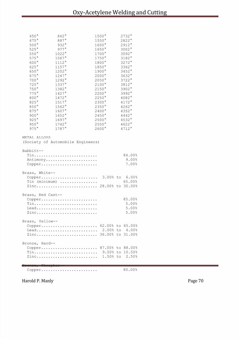
7/30/2019 Oxy Acetylene Welding and Cutting
http://slidepdf.com/reader/full/oxy-acetylene-welding-and-cutting 70/106
Oxy-Acetylene Welding and Cutting
Harold P. Manly Page 70
450° 842° 1500° 2732°475° 887° 1550° 2822°
500° 932° 1600° 2912°525° 977° 1650° 3002°550° 1022° 1700° 3092°
575° 1067° 1750° 3182°600° 1112° 1800° 3272°625° 1157° 1850° 3362°650° 1202° 1900° 3452°675° 1247° 2000° 3632°700° 1292° 2050° 3722°725° 1337° 2100° 3812°750° 1382° 2150° 3902°775° 1427° 2200° 3992°800° 1472° 2250° 4082°
825° 1517° 2300° 4172°850° 1562° 2350° 4262°875° 1607° 2400° 4352°900° 1652° 2450° 4442°
925° 1697° 2500° 4532°950° 1742° 2550° 4622°975° 1787° 2600° 4712°
METAL ALLOYS(Society of Automobile Engineers)
Babbitt--Tin........................... 84.00%Antimony...................... 9.00%Copper........................ 7.00%
Brass, White--
Copper........................ 3.00% to 6.00%Tin (minimum) ................ 65.00%Zinc.......................... 28.00% to 30.00%
Brass, Red Cast--Copper........................ 85.00%Tin........................... 5.00%Lead.......................... 5.00%Zinc.......................... 5.00%
Brass, Yellow--
Copper........................ 62.00% to 65.00%Lead.......................... 2.00% to 4.00%Zinc.......................... 36.00% to 31.00%
Bronze, Hard--Copper........................ 87.00% to 88.00%Tin........................... 9.50% to 10.50%Zinc.......................... 1.50% to 2.50%
Bronze, Phosphor--Copper........................ 80.00%
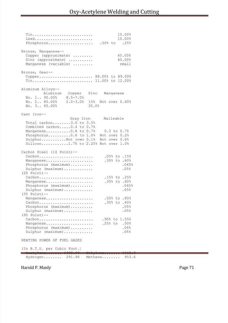
7/30/2019 Oxy Acetylene Welding and Cutting
http://slidepdf.com/reader/full/oxy-acetylene-welding-and-cutting 71/106
Oxy-Acetylene Welding and Cutting
Harold P. Manly Page 71
Tin........................... 10.00%Lead.......................... 10.00%
Phosphorus.................... .50% to .25%
Bronze, Manganese--
Copper (approximate) ......... 60.00%Zinc (approximate) ........... 40.00%Manganese (variable) ......... small
Bronze, Gear--Copper........................ 88.00% to 89.00%Tin........................... 11.00% to 12.00%
Aluminum Alloys--Aluminum Copper Zinc Manganese
No. 1.. 90.00% 8.5-7.0%No. 2.. 80.00% 2.0-3.0% 15% Not over 0.40%No. 3.. 65.00% 35.0%
Cast Iron--Gray Iron Malleable
Total carbon........3.0 to 3.5%Combined carbon.....0.4 to 0.7%Manganese...........0.4 to 0.7% 0.3 to 0.7%Phosphorus..........0.6 to 1.0% Not over 0.2%Sulphur...........Not over 0.1% Not over 0.6%Silicon............1.75 to 2.25% Not over 1.0%
Carbon Steel (10 Point)--Carbon........................ .05% to .15%Manganese..................... .30% to .60%Phosphorus (maximum).......... .045%
Sulphur (maximum)............. .05%(20 Point)--Carbon........................ .15% to .25%Manganese..................... .30% to .60%Phosphorus (maximum).......... .045%Sulphur (maximum)............. .05%
(35 Point)--Manganese..................... .50% to .80%Carbon........................ .30% to .40%Phosphorus (maximum).......... .05%Sulphur (maximum)............. .05%
(95 Point)--Carbon........................ .90% to 1.05%Manganese..................... .25% to .50%
Phosphorus (maximum).......... .04%Sulphur (maximum)............. .05%
HEATING POWER OF FUEL GASES
(In B.T.U. per Cubic Foot.)
Acetylene....... 1498.99 Ethylene....... 1562.9Hydrogen........ 291.96 Methane........ 953.6
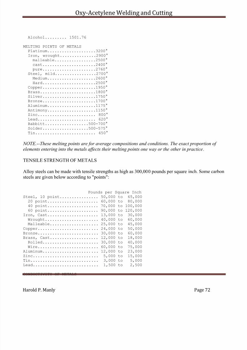
7/30/2019 Oxy Acetylene Welding and Cutting
http://slidepdf.com/reader/full/oxy-acetylene-welding-and-cutting 72/106
Oxy-Acetylene Welding and Cutting
Harold P. Manly Page 72
Alcohol......... 1501.76
MELTING POINTS OF METALSPlatinum....................3200°Iron, wrought...............2900°
malleable.................2500°cast......................2400°pure......................2760°
Steel, mild.................2700°Medium....................2600°Hard......................2500°
Copper......................1950°Brass.......................1800°Silver......................1750°Bronze......................1700°
Aluminum....................1175°Antimony....................1150°Zinc........................ 800°Lead........................ 620°
Babbitt..................500-700°Solder...................500-575°Tin......................... 450°
NOTE.--These melting points are for average compositions and conditions. The exact proportion of
elements entering into the metals affects their melting points one way or the other in practice.
TENSILE STRENGTH OF METALS
Alloy steels can be made with tensile strengths as high as 300,000 pounds per square inch. Some carbonsteels are given below according to "points":
Pounds per Square InchSteel, 10 point................ 50,000 to 65,00020 point..................... 60,000 to 80,00040 point..................... 70,000 to 100,00060 point..................... 90,000 to 120,000
Iron, Cast..................... 13,000 to 30,000Wrought...................... 40,000 to 60,000Malleable.................... 25,000 to 45,000
Copper......................... 24,000 to 50,000Bronze......................... 30,000 to 60,000Brass, Cast.................... 12,000 to 18,000Rolled....................... 30,000 to 40,000
Wire......................... 60,000 to 75,000Aluminum....................... 12,000 to 23,000Zinc........................... 5,000 to 15,000Tin............................ 3,000 to 5,000Lead........................... 1,500 to 2,500
CONDUCTIVITY OF METALS

7/30/2019 Oxy Acetylene Welding and Cutting
http://slidepdf.com/reader/full/oxy-acetylene-welding-and-cutting 73/106
Oxy-Acetylene Welding and Cutting
Harold P. Manly Page 73
(Based on the Value of Silver as 100)
Heat ElectricitySilver....................100 100Copper.................... 74 99
Aluminum.................. 38 63Brass..................... 23 22Zinc...................... 19 29Tin....................... 14 15Wrought Iron.............. 12 16Steel..................... 11.5 12Cast Iron................. 11 12Bronze.................... 9 7Lead...................... 8 9
WEIGHT OF METALS
(Per Cubic Inch)Pounds Pounds
Lead............ .410 Wrought Iron..... .278Copper.......... .320 Tin.............. .263Bronze.......... .313 Cast Iron........ .260Brass........... .300 Zinc............. .258Steel........... .283 Aluminum......... .093
EXPANSION OF METALS
(Measured in Thousandths of an Inch per Foot ofLength When Raised 1000 Degrees in Temperature)
Inch InchLead............ .188 Brass............ .115Zinc............ .168 Copper........... .106
Aluminum........ .148 Steel............ .083Silver.......... .129 Wrought Iron..... .078Bronze.......... .118 Cast Iron........ .068
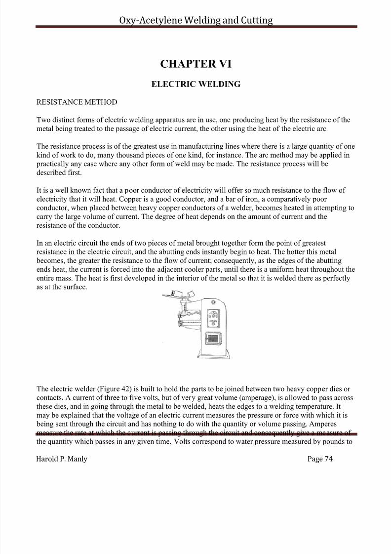
7/30/2019 Oxy Acetylene Welding and Cutting
http://slidepdf.com/reader/full/oxy-acetylene-welding-and-cutting 74/106
Oxy-Acetylene Welding and Cutting
Harold P. Manly Page 74
CHAPTER VI
ELECTRIC WELDING
RESISTANCE METHOD
Two distinct forms of electric welding apparatus are in use, one producing heat by the resistance of themetal being treated to the passage of electric current, the other using the heat of the electric arc.
The resistance process is of the greatest use in manufacturing lines where there is a large quantity of onekind of work to do, many thousand pieces of one kind, for instance. The arc method may be applied in practically any case where any other form of weld may be made. The resistance process will bedescribed first.
It is a well known fact that a poor conductor of electricity will offer so much resistance to the flow of electricity that it will heat. Copper is a good conductor, and a bar of iron, a comparatively poor conductor, when placed between heavy copper conductors of a welder, becomes heated in attempting tocarry the large volume of current. The degree of heat depends on the amount of current and theresistance of the conductor.
In an electric circuit the ends of two pieces of metal brought together form the point of greatestresistance in the electric circuit, and the abutting ends instantly begin to heat. The hotter this metal becomes, the greater the resistance to the flow of current; consequently, as the edges of the abuttingends heat, the current is forced into the adjacent cooler parts, until there is a uniform heat throughout theentire mass. The heat is first developed in the interior of the metal so that it is welded there as perfectlyas at the surface.
The electric welder (Figure 42) is built to hold the parts to be joined between two heavy copper dies or contacts. A current of three to five volts, but of very great volume (amperage), is allowed to pass acrossthese dies, and in going through the metal to be welded, heats the edges to a welding temperature. Itmay be explained that the voltage of an electric current measures the pressure or force with which it is being sent through the circuit and has nothing to do with the quantity or volume passing. Amperesmeasure the rate at which the current is passing through the circuit and consequently give a measure of the quantity which passes in any given time. Volts correspond to water pressure measured by pounds to
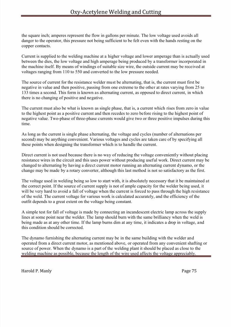
7/30/2019 Oxy Acetylene Welding and Cutting
http://slidepdf.com/reader/full/oxy-acetylene-welding-and-cutting 75/106
Oxy-Acetylene Welding and Cutting
Harold P. Manly Page 75
the square inch; amperes represent the flow in gallons per minute. The low voltage used avoids alldanger to the operator, this pressure not being sufficient to be felt even with the hands resting on thecopper contacts.
Current is supplied to the welding machine at a higher voltage and lower amperage than is actually used between the dies, the low voltage and high amperage being produced by a transformer incorporated inthe machine itself. By means of windings of suitable size wire, the outside current may be received atvoltages ranging from 110 to 550 and converted to the low pressure needed.
The source of current for the resistance welder must be alternating, that is, the current must first benegative in value and then positive, passing from one extreme to the other at rates varying from 25 to133 times a second. This form is known as alternating current, as opposed to direct current, in whichthere is no changing of positive and negative.
The current must also be what is known as single phase, that is, a current which rises from zero in value
to the highest point as a positive current and then recedes to zero before rising to the highest point of negative value. Two-phase of three-phase currents would give two or three positive impulses during thistime.
As long as the current is single phase alternating, the voltage and cycles (number of alternations per second) may be anything convenient. Various voltages and cycles are taken care of by specifying allthese points when designing the transformer which is to handle the current.
Direct current is not used because there is no way of reducing the voltage conveniently without placingresistance wires in the circuit and this uses power without producing useful work. Direct current may bechanged to alternating by having a direct current motor running an alternating current dynamo, or the
change may be made by a rotary converter, although this last method is not so satisfactory as the first.
The voltage used in welding being so low to start with, it is absolutely necessary that it be maintained atthe correct point. If the source of current supply is not of ample capacity for the welder being used, itwill be very hard to avoid a fall of voltage when the current is forced to pass through the high resistanceof the weld. The current voltage for various work is calculated accurately, and the efficiency of theoutfit depends to a great extent on the voltage being constant.
A simple test for fall of voltage is made by connecting an incandescent electric lamp across the supplylines at some point near the welder. The lamp should burn with the same brilliancy when the weld is being made as at any other time. If the lamp burns dim at any time, it indicates a drop in voltage, and
this condition should be corrected.
The dynamo furnishing the alternating current may be in the same building with the welder andoperated from a direct current motor, as mentioned above, or operated from any convenient shafting or source of power. When the dynamo is a part of the welding plant it should be placed as close to thewelding machine as possible, because the length of the wire used affects the voltage appreciably.
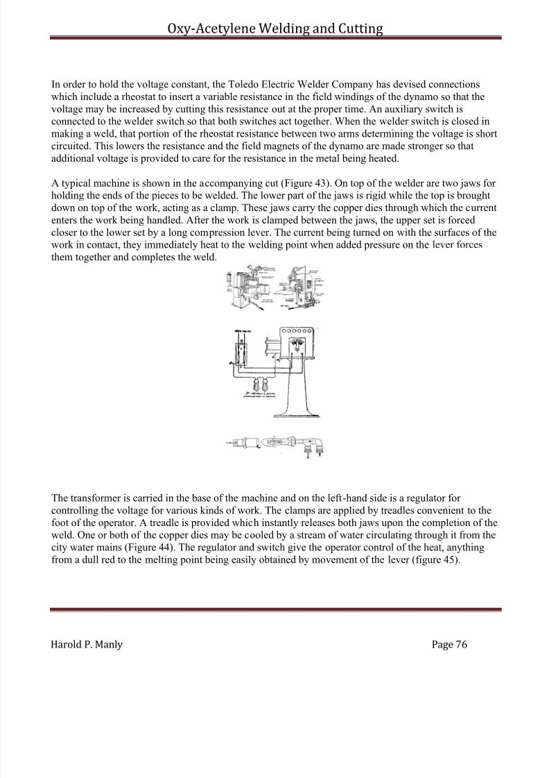
7/30/2019 Oxy Acetylene Welding and Cutting
http://slidepdf.com/reader/full/oxy-acetylene-welding-and-cutting 76/106
Oxy-Acetylene Welding and Cutting
Harold P. Manly Page 76
In order to hold the voltage constant, the Toledo Electric Welder Company has devised connectionswhich include a rheostat to insert a variable resistance in the field windings of the dynamo so that thevoltage may be increased by cutting this resistance out at the proper time. An auxiliary switch isconnected to the welder switch so that both switches act together. When the welder switch is closed in
making a weld, that portion of the rheostat resistance between two arms determining the voltage is shortcircuited. This lowers the resistance and the field magnets of the dynamo are made stronger so thatadditional voltage is provided to care for the resistance in the metal being heated.
A typical machine is shown in the accompanying cut (Figure 43). On top of the welder are two jaws for holding the ends of the pieces to be welded. The lower part of the jaws is rigid while the top is broughtdown on top of the work, acting as a clamp. These jaws carry the copper dies through which the currententers the work being handled. After the work is clamped between the jaws, the upper set is forcedcloser to the lower set by a long compression lever. The current being turned on with the surfaces of thework in contact, they immediately heat to the welding point when added pressure on the lever forcesthem together and completes the weld.
The transformer is carried in the base of the machine and on the left-hand side is a regulator for controlling the voltage for various kinds of work. The clamps are applied by treadles convenient to thefoot of the operator. A treadle is provided which instantly releases both jaws upon the completion of theweld. One or both of the copper dies may be cooled by a stream of water circulating through it from the
city water mains (Figure 44). The regulator and switch give the operator control of the heat, anythingfrom a dull red to the melting point being easily obtained by movement of the lever (figure 45).

7/30/2019 Oxy Acetylene Welding and Cutting
http://slidepdf.com/reader/full/oxy-acetylene-welding-and-cutting 77/106
Oxy-Acetylene Welding and Cutting
Harold P. Manly Page 77
Welding.--It is not necessary to give the metal to be welded any special preparation, although when veryrusty or covered with scale, the rust and scale should be removed sufficiently to allow good contact of clean metal on the copper dies. The cleaner and better the stock, the less current it takes, and there isless wear on the dies. The dies should be kept firm and tight in their holders to make a good contact. All bolts and nuts fastening the electrical contacts should be clean and tight at all times.
The scale may be removed from forgings by immersing them in a pickling solution in a wood, stone or lead-lined tank.
The solution is made with five gallons of commercial sulphuric acid in 150 gallons of water. To get thequickest and best results from this method, the solution should be kept as near the boiling point as possible by having a coil of extra heavy lead pipe running inside the tank and carrying live steam. Avery few minutes in this bath will remove the scale and the parts should then be washed in runningwater. After this washing they should be dipped into a bath of 50 pounds of unslaked lime in 150gallons of water to neutralize any trace of acid.
Cast iron cannot be commercially welded, as it is high in carbon and silicon, and passes suddenly from a
crystalline to a fluid state when brought to the welding temperature. With steel or wrought iron thetemperature must be kept below the melting point to avoid injury to the metal. The metal must be heatedquickly and pressed together with sufficient force to push all burnt metal out of the joint.
High carbon steel can be welded, but must be annealed after welding to overcome the strains set up bythe heat being applied at one place. Good results are hard to obtain when the carbon runs as high as 75 points, and steel of this class can only be handled by an experienced operator. If the steel is below 25 points in carbon content, good welds will always be the result. To weld high carbon to low carbon steel,the stock should be clamped in the dies with the low carbon stock sticking considerably further out fromthe die than the high carbon stock. Nickel steel welds readily, the nickel increasing the strength of theweld.
Iron and copper may be welded together by reducing the size of the copper end where it comes incontact with the iron. When welding copper and brass the pressure must be less than when welding iron.The metal is allowed to actually fuse or melt at the juncture and the pressure must be sufficient to forcethe burned metal out. The current is cut off the instant the metal ends begin to soften, this being done bymeans of an automatic switch which opens when the softening of the metal allows the ends to come
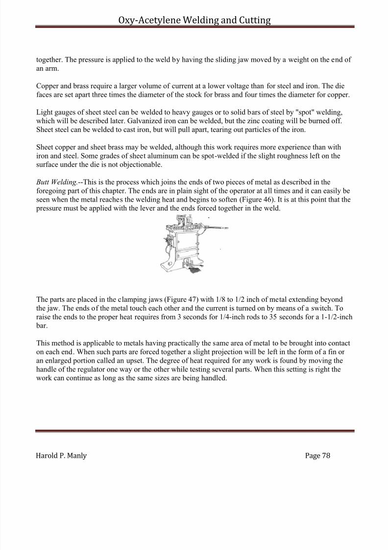
7/30/2019 Oxy Acetylene Welding and Cutting
http://slidepdf.com/reader/full/oxy-acetylene-welding-and-cutting 78/106
Oxy-Acetylene Welding and Cutting
Harold P. Manly Page 78
together. The pressure is applied to the weld by having the sliding jaw moved by a weight on the end of an arm.
Copper and brass require a larger volume of current at a lower voltage than for steel and iron. The die
faces are set apart three times the diameter of the stock for brass and four times the diameter for copper.
Light gauges of sheet steel can be welded to heavy gauges or to solid bars of steel by "spot" welding,which will be described later. Galvanized iron can be welded, but the zinc coating will be burned off.Sheet steel can be welded to cast iron, but will pull apart, tearing out particles of the iron.
Sheet copper and sheet brass may be welded, although this work requires more experience than withiron and steel. Some grades of sheet aluminum can be spot-welded if the slight roughness left on thesurface under the die is not objectionable.
Butt Welding.--This is the process which joins the ends of two pieces of metal as described in the
foregoing part of this chapter. The ends are in plain sight of the operator at all times and it can easily beseen when the metal reaches the welding heat and begins to soften (Figure 46). It is at this point that the pressure must be applied with the lever and the ends forced together in the weld.
The parts are placed in the clamping jaws (Figure 47) with 1/8 to 1/2 inch of metal extending beyondthe jaw. The ends of the metal touch each other and the current is turned on by means of a switch. Toraise the ends to the proper heat requires from 3 seconds for 1/4-inch rods to 35 seconds for a 1-1/2-inch bar.
This method is applicable to metals having practically the same area of metal to be brought into contacton each end. When such parts are forced together a slight projection will be left in the form of a fin or an enlarged portion called an upset. The degree of heat required for any work is found by moving thehandle of the regulator one way or the other while testing several parts. When this setting is right thework can continue as long as the same sizes are being handled.
7/30/2019 Oxy Acetylene Welding and Cutting
http://slidepdf.com/reader/full/oxy-acetylene-welding-and-cutting 79/106
Oxy-Acetylene Welding and Cutting
Harold P. Manly Page 79
Copper, brass, tool steel and all other metals that are harmed by high temperatures must be heatedquickly and pressed together with sufficient force to force all burned metal from the weld.
In case it is desired to make a weld in the form of a capital letter T, it is necessary to heat the partcorresponding to the top bar of the T to a bright red, then bring the lower bar to the pre-heated one andagain turn on the current, when a weld can be quickly made.
Spot Welding.--This is a method of joining metal sheets together at any desired point by a welded spotabout the size of a rivet. It is done on a spot welder by fusing the metal at the point desired and at thesame instant applying sufficient pressure to force the particles of molten metal together. The dies areusually placed one above the other so that the work may rest on the lower one while the upper one is brought down on top of the upper sheet to be welded.
One of the dies is usually pointed slightly, the opposing one being left flat. The pointed die leaves aslight indentation on one side of the metal, while the other side is left smooth. The dies may be reversedso that the outside surface of any work may be left smooth. The current is allowed to flow through thedies by a switch which is closed after pressure is applied to the work.
There is a limit to the thickness of sheet metal that can be welded by this process because of the fact thatthe copper rods can only carry a certain quantity of current without becoming unduly heated themselves.Another reason is that it is difficult to make heavy sections of metal touch at the welding point withoutexcessive pressure.
Lap welding is the process used when two pieces of metal are caused to overlap and when brought to awelding heat are forced together by passing through rollers, or under a press, thus leaving the welded joint practically the same thickness as the balance of the work.
Where it is desirable to make a continuous seam, a special machine is required, or an attachment for oneof the other types. In this form of work the stock must be thoroughly cleaned and is then passed betweencopper rollers which act in the same capacity as the copper dies.
Other Applications.--Hardening and tempering can be done by clamping the work in the welding diesand setting the control and time to bring the metal to the proper color, when it is cooled in the usualmanner.
7/30/2019 Oxy Acetylene Welding and Cutting
http://slidepdf.com/reader/full/oxy-acetylene-welding-and-cutting 80/106
Oxy-Acetylene Welding and Cutting
Harold P. Manly Page 80
Brazing is done by clamping the work in the jaws and heating until the flux, then the spelter has meltedand run into the joint. Riveting and heading of rivets can be done by bringing the dies down on oppositeends of the rivet after it has been inserted in the hole, the dies being shaped to form the heads properly.
Hardened steel may be softened and annealed so that it can be machined by connecting the dies of thewelder to each side of the point to be softened. The current is then applied until the work has reached a point at which it will soften when cooled.
Troubles and Remedies.--The following methods have been furnished by the Toledo Electric Welder Company and are recommended for this class of work whenever necessary.
To locate grounds in the primary or high voltage side of the circuit, connect incandescent lamps inseries by means of a long piece of lamp cord, as shown, in Figure 43a. For 110 volts use one lamp, for 220 volts use two lamps and for 440 volts use four lamps. Attach one end of the lamp cord to one sideof the switch, and close the switch. Take the other end of the cord in the hand and press it against some
part of the welder frame where the metal is clean and bright. Paint, grease and dirt act as insulators and prevent electrical contact. If the lamp lights, the circuit is in electrical contact with the frame; in other words, grounded. If the lamps do not light, connect the wire to a terminal block, die or slide. If thelamps then light, the circuit, coils or leads are in electrical contact with the large coil in the transformer or its connections.
If, however, the lamps do not light in either case, the lamp cord should be disconnected from the switchand connected to the other side, and the operations of connecting to welder frame, dies, terminal blocks,etc., as explained above, should be repeated. If the lamps light at any of these connections, a "ground" isindicated. "Grounds" can usually be found by carefully tracing the primary circuit until a place is foundwhere the insulation is defective. Reinsulate and make the above tests again to make sure everything is
clear. If the ground can not be located by observation, the various parts of the primary circuit should bedisconnected, and the transformer, switch, regulator, etc., tested separately.
To locate a ground in the regulator or other part, disconnect the lines running to the welder from theswitch. The test lamps used in the previous tests are connected, one end of lamp cord to the switch, theother end to a binding post of the regulator. Connect the other side of the switch to some part of theregulator housing. (This must be a clean connection to a bolt head or the paint should be scraped off.)Close the switch. If the lamps light, the regulator winding or some part of the switch is "grounded" tothe iron base or core of the regulator. If the lamps do not light, this part of the apparatus is clear.
This test can be easily applied to any part of the welder outfit by connecting to the current carrying part
of the apparatus, and to the iron base or frame that should not carry current. If the lamps light, itindicates that the insulation is broken down or is defective.
An A.C. voltmeter can, of course, be substituted for the lamps, or a D.C. voltmeter with D.C. currentcan be used in making the tests.

7/30/2019 Oxy Acetylene Welding and Cutting
http://slidepdf.com/reader/full/oxy-acetylene-welding-and-cutting 81/106

7/30/2019 Oxy Acetylene Welding and Cutting
http://slidepdf.com/reader/full/oxy-acetylene-welding-and-cutting 82/106
Oxy-Acetylene Welding and Cutting
Harold P. Manly Page 82
the circuit. Some caution must be used in making the above test, as in case one terminal is heavilygrounded the testing wire may be fused if allowed to stay in contact with the die.
The Remedy.--Clean the slides, dies and terminal blocks thoroughly and dry out the fibre insulation if it
is damp. See that no scale or metal has worked under the sliding parts, and that the secondary leads donot touch the frame. If the ground is very heavy it may be necessary to remove the slides in order tofacilitate the examination and removal of the ground. Insulation, where torn or worn through, must becarefully replaced or taped. If the transformer coils are grounded to the iron core of the transformer or tothe secondary, it may be necessary to remove the coils and reinsulate them at the points of contact. Ashort circuited coil will heat excessively and eventually burn out. This may mean a new coil if you areunable to repair the old one. In all cases the transformer windings should be protected from mechanicalinjury or dampness. Unless excessively overloaded, transformers will last for years without giving amoment's trouble, if they are not exposed to moisture or are not injured mechanically.
The most common trouble arises from poor electrical contacts, and they are the cause of endless trouble
and annoyance. See that all connections are clean and bright. Take out the dies every day or two and seethat there is no scale, grease or dirt between them and the holders. Clean them thoroughly beforereplacing. Tighten the bolts running from the transformer leads to the work jaws.
ELECTRIC ARC WELDING
This method bears no relation to the one just considered, except that the source of heat is the same in both cases. Arc welding makes use of the flame produced by the voltaic arc in practically the same waythat oxy-acetylene welding uses the flame from the gases.
If the ends of two pieces of carbon through which a current of electricity is flowing while they are in
contact are separated from each other quite slowly, a brilliant arc of flame is formed between themwhich consists mainly of carbon vapor. The carbons are consumed by combination with the oxygen inthe air and through being turned to a gas under the intense heat.
The most intense action takes place at the center of the carbon which carries the positive current and thisis the point of greatest heat. The temperature at this point in the arc is greater than can be produced byany other means under human control.
An arc may be formed between pieces of metal, called electrodes, in the same way as between carbon.The metallic arc is called a flaming arc and as the metal of the electrode burns with the heat, it gives theflame a color characteristic of the material being used. The metallic arc may be drawn out to a much
greater length than one formed between carbon electrodes.
Arc Welding is carried out by drawing a piece of carbon which is of negative polarity away from the pieces of metal to be welded while the metal is made positive in polarity. The negative wire is fastenedto the carbon electrode and the work is laid on a table made of cast or wrought iron to which the positivewire is made fast. The direction of the flame is then from the metal being welded to the carbon and thework is thus prevented from being saturated with carbon, which would prove very detrimental to its

7/30/2019 Oxy Acetylene Welding and Cutting
http://slidepdf.com/reader/full/oxy-acetylene-welding-and-cutting 83/106
Oxy-Acetylene Welding and Cutting
Harold P. Manly Page 83
strength. A secondary advantage is found in the fact that the greatest heat is at the metal being welded because of its being the positive electrode.
The carbon electrode is usually made from one quarter to one and a half inches in diameter and from six
to twelve inches in length. The length of the arc may be anywhere from one inch to four inches,depending on the size of the work being handled.
While the parts are carefully insulated to avoid danger of shock, it is necessary for the operator to wear rubber gloves as a further protection, and to wear some form of hood over the head to shield him againstthe extreme heat liberated. This hood may be made from metal, although some material that does notconduct electricity is to be preferred. The work is watched through pieces of glass formed with onesheet, which is either blue or green, placed over another which is red. Screens of glass are sometimesused without the head protector. Some protection for the eyes is absolutely necessary because of theintense white light.
It is seldom necessary to preheat the work as with the gas processes, because the heat is localized at the point of welding and the action is so rapid that the expansion is not so great. The necessity of preheating, however, depends entirely on the material, form and size of the work being handled. Thesame advice applies to arc welding as to the gas flame method but in a lesser degree. Filling rods areused in the same way as with any other flame process.
It is the purpose of this explanation to state the fundamental principles of the application of the electricarc to welding metals, and by applying the principles the following questions will be answered:
What metals can be welded by the electric arc?
What difficulties are to be encountered in applying the electric arc to welding?
What is the strength of the weld in comparison with the original piece?
What is the function of the arc welding machine itself?
What is the comparative application of the electric arc and the oxy-acetylene method and others of asimilar nature?
The answers to these questions will make it possible to understand the application of this process to anywork. In a great many places the use of the arc is cutting the cost of welding to a very small fraction of
what it would be by any other method, so that the importance of this method may be well understood.
Any two metals which are brought to the melting temperature and applied to each other will adhere sothat they are no more apt to break at the weld than at any other point outside of the weld. It is the property of all metals to stick together under these conditions. The electric arc is used in this connectionmerely as a heating agent. This is its only function in the process.
7/30/2019 Oxy Acetylene Welding and Cutting
http://slidepdf.com/reader/full/oxy-acetylene-welding-and-cutting 84/106
Oxy-Acetylene Welding and Cutting
Harold P. Manly Page 84
It has advantages in its ease of application and the cheapness with which heat can be liberated at anygiven point by its use. There is nothing in connection with arc welding that the above principles will notanswer; that is, that metals at the melting point will weld and that the electric arc will furnish the heat to bring them to this point. As to the first question, what metals can be welded, all metals can be welded.
The difficulties which are encountered are as follows:
In the case of brass or zinc, the metals will be covered with a coat of zinc oxide before they reach awelding heat. This zinc oxide makes it impossible for two clean surfaces to come together and somemethod has to be used for eliminating this possibility and allowing the two surfaces to join without the possibility of the oxide intervening. The same is true of aluminum, in which the oxide, alumina, will beformed, and with several other alloys comprising elements of different melting points.
In order to eliminate these oxides, it is necessary in practical work, to puddle the weld; this is, to have asufficient quantity of molten metal at the weld so that the oxide is floated away. When this is done, the
two surfaces which are to be joined are covered with a coat of melted metal on which floats the oxideand other impurities. The two pieces are thus allowed to join while their surfaces are protected. This precaution is not necessary in working with steel except in extreme cases.
Another difficulty which is met with in the welding of a great many metals is their expansion under heat, which results in so great a contraction when the weld cools that the metal is left with aconsiderable strain on it. In extreme cases this will result in cracking at the weld or near it. To eliminatethis danger it is necessary to apply heat either all over the piece to be welded or at certain points. In thecase of cast iron and sometimes with copper it is necessary to anneal after welding, since otherwise thewelded pieces will be very brittle on account of the chilling. This is also true of malleable iron.
Very thin metals which are welded together and are not backed up by something to carry away theexcess heat, are very apt to burn through, leaving a hole where the weld should be. This difficulty can beeliminated by backing up the weld with a metal face or by decreasing the intensity of the arc so that thismelting through will not occur. However, the practical limit for arc welding without backing up thework with a metal face or decreasing the intensity of the arc is approximately 22 gauge, although thinner metal can be welded by a very skillful and careful operator.
One difficulty with arc welding is the lack of skillful operators. This method is often looked upon as being something out of the ordinary and governed by laws entirely different from other welding. As amatter of fact, it does not take as much skill to make a good arc weld as it does to make a good weld in aforge fire as the blacksmith does it. There are few jobs which cannot be handled successfully by an
operator of average intelligence with one week's instructions, although his work will become better and better in quality as he continues to use the arc.
Now comes the question of the strength of the weld after it has been made. This strength is equally asgreat as that of the metal that is used to make the weld. It should be remembered, however, that themetal which goes into the weld is put in there as a casting and has not been rolled. This would make thestrength of the weld as great as the same metal that is used for filling if in the cast form.
7/30/2019 Oxy Acetylene Welding and Cutting
http://slidepdf.com/reader/full/oxy-acetylene-welding-and-cutting 85/106
Oxy-Acetylene Welding and Cutting
Harold P. Manly Page 85
Two pieces of steel could be welded together having a tensile strength at the weld of 50,000 pounds.Higher strengths than this can be obtained by the use of special alloys for the filling material or byrolling. Welds with a tensile strength as great as mentioned will give a result which is perfectlysatisfactory in almost all cases.
There are a great many jobs where it is possible to fill up the weld, that is, make the section at the pointof the weld a little larger than the section through the rest of the piece. By doing this, the disadvantagesof the weld being in the form of a casting in comparison with the rest of the piece being in the form of rolled steel can be overcome, and make the weld itself even stronger than the original piece.
The next question is the adaptability of the electric arc in comparison with forge fire, oxy-acetylene or other method. The answer is somewhat difficult if made general. There are no doubt some cases wherethe use of a drop hammer and forge fire or the use of the oxy-acetylene torch will make, all things beingconsidered, a better job than the use of the electric arc, although a case where this is absolutely proved israre.
The electric arc will melt metal in a weld for less than the same metal can be melted by the use of theoxy-acetylene torch, and, on account of the fact that the heat can be applied exactly where it is requiredand in the amount required, the arc can in almost all cases supply welding heat for less cost than a forgefire or heating furnace.
The one great advantage of the oxy-acetylene method in comparison with other methods of welding isthe fact that in some cases of very thin sheet, the weld can be made somewhat sooner than is possibleotherwise. With metal of 18 gauge or thicker, this advantage is eliminated. In cutting steel, the oxy-acetylene torch is superior to almost any other possible method.
Arc Welding Machines.--A consideration of the function and purpose of the various types of arc weldingmachines shows that the only reason for the use of any machine is either for conversion of the currentfrom alternating to direct, or, if the current is already direct, then the saving in the application of thiscurrent in the arc.
It is practically out of the question to apply an alternating current arc to welding for the reason that inany arc practically all the heat is liberated at the positive electrode, which means that, in alternatingcurrent, half the heat is liberated at each electrode as the current changes its direction of flow or alternates. Another disadvantage of the alternating arc is that it is difficult of control and application.
In all arc welding by the use of the carbon arc, the positive electrode is made the piece to be welded,
while in welding with metallic electrodes this may be either the piece to be welded of the rod that isused as a filler. The voltage across the arc is a variable quantity, depending on the length of the flame,its temperature and the gases liberated in the arc. With a carbon electrode the voltage will vary fromzero to forty-five volts. With the metallic electrode the voltage will vary from zero to thirty volts. It is,therefore, necessary for the welding machine to be able to furnish to the arc the requisite amount of current, this amount being varied, and furnish it at all times at the voltage required.
7/30/2019 Oxy Acetylene Welding and Cutting
http://slidepdf.com/reader/full/oxy-acetylene-welding-and-cutting 86/106
Oxy-Acetylene Welding and Cutting
Harold P. Manly Page 86
The simplest welding apparatus is a resistance in series with the arc. This is entirely satisfactory inevery way except in cost of current. By the use of resistance in series with the arc and using 220 volts asthe supply, from eighty to ninety per cent of the current is lost in heat at the resistance. Another disadvantage is the fact that most materials change their resistance as their temperature changes, thus
making the amount of current for the arc a variable quantity, depending on the temperature of theresistance.
There have been various methods originated for saving the power mentioned and a good many machineshave been put on the market for this purpose. All of them save some power over what a plain resistancewould use. Practically all arc welding machines at the present time are motor generator sets, the motor of which is arranged for the supply voltage and current, this motor being direct connected to acompound wound generator delivering approximately seventy-five volts direct current. Then by the useof a resistance, this seventy-five volt supply is applied to the arc. Since the voltage across the arc willvary from zero to fifty volts, this machine will save from zero up to seventy per cent of the power thatthe machine delivers. The rest of the power, of course, has to be dissipated in the resistance used in
series with the arc.
A motor generator set which can be purchased from any electrical company, with a long piece of fencewire wound around a piece of asbestos, gives results equally as good and at a very small part of the firstcost.
It is possible to construct a machine which will eliminate all losses in the resistance; in other words,eliminate all resistance in series with the arc. A machine of this kind will save its cost within a veryshort time, providing the welder is used to any extent.
Putting it in figures, the results are as follows for average conditions. Current at 2c per kilowatt hour,
metallic electrode arc of 150 amperes, carbon arc 500 amperes; voltage across the metallic electrode arc20, voltage across the carbon arc 35. Supply current 220 volts, direct. In the case of the metallicelectrode, if resistance is used, the cost of running this arc is sixty-six cents per hour. With the carbonelectrode, $2.20 per hour. If a motor generator set with a seventy volt constant potential machine is usedfor a welder, the cost will be as follows:
Metallic electrode 25.2c. Carbon electrode 84c per hour. With a machine which will deliver the requiredvoltage at the arc and eliminate all the resistance in series with the arc, the cost will be as follows:Metallic electrode 7.2c per hour; carbon electrode 42c per hour. This is with the understanding that thearc is held constant and continuously at its full value. This, however, is practically impossible and theactual load factor is approximately fifty per cent, which would mean that operating a welder as it is
usually operated, this result will be reduced to one-half of that stated in all cases.

7/30/2019 Oxy Acetylene Welding and Cutting
http://slidepdf.com/reader/full/oxy-acetylene-welding-and-cutting 87/106
Oxy-Acetylene Welding and Cutting
Harold P. Manly Page 87
CHAPTER VII
HAND FORGING AND WELDING
Smithing, or blacksmithing, is the process of working heated iron, steel or other metals by forging, bending or welding them.
The Forge.--The metal is heated in a forge consisting of a shallow pan for holding the fire, in the center of which is an opening from below through which air is forced to make a hot fire.
Air is forced through this hole, called a "tuyere" (Figure 48) by means of a hand bellows, a rotary fanoperated with crank or lever, or with a fan driven from an electric motor. The harder the air is driveninto the fire above the tuyere the more oxygen is furnished and the hotter the fire becomes.
Directly below the tuyere is an opening through which the ashes that drop from the fire may be cleanedout.
The Fire.--The fire is made by placing a small piece of waste soaked in oil, kerosene or gasoline, over the tuyere, lighting the waste, then starting the fan or blower slowly. Gradually cover the waste, while itis burning brightly, with a layer of soft coal. The coal will catch fire and burn after the waste has been
consumed. A piece of waste half the size of a person's hand is ample for this purpose.
The fuel should be "smithing coal." A lump of smithing coal breaks easily, shows clean and even on allsides and should not break into layers. The coal is broken into fine pieces and wet before being used onthe fire.
The fire should be kept deep enough so that there is always three or four inches of fire below the pieceof metal to be heated and there should be enough fire above the work so that no part of the metal beingheated comes in contact with the air. The fire should be kept as small as possible while following theserules as to depth.
To make the fire larger, loosen the coal around the edges. To make the fire smaller, pack wet coalaround the edges in a compact mass and loosen the fire in the center. Add fresh coal only around theedges of the fire. It will turn to coke and can then be raked onto the fire. Blow only enough air into thefire to keep it burning brightly, not so much that the fire is blown up through the top of the coal pack.To prevent the fire from going out between jobs, stick a piece of soft wood into it and cover with freshwet coal.

7/30/2019 Oxy Acetylene Welding and Cutting
http://slidepdf.com/reader/full/oxy-acetylene-welding-and-cutting 88/106
Oxy-Acetylene Welding and Cutting
Harold P. Manly Page 88
Tools.--The hammer is a ball pene, or blacksmith's hammer, weighing about a pound and a half.
The sledge is a heavy hammer, weighing from 5 to 20 pounds and having a handle 30 to 36 inches long.
The anvil is a heavy piece of wrought iron (Figure 49), faced with steel and having four legs. It has a pointed horn on one end, an overhanging tail on the other end and a flat top. In the tail there is a squarehole called the "hardie" hole and a round one called the "spud" hole.
Tongs, with handles about one foot long and jaws suitable for holding the work, are used. To secure afirm grip on the work, the jaws may be heated red hot and hammered into shape over the piece to beheld, thus giving a properly formed jaw. Jaws should touch the work along their entire length.
The set hammer is a hammer, one end of whose head is square and flat, and from this face the headtapers evenly to the other face. The large face is about 1-1/4 inches square.
The flatter is a hammer having one face of its head flat and about 2-1/2 inches square.
Swages are hammers having specially formed faces for finishing rounds, squares, hexagons, ovals,tapers, etc.
Fullers are hammers having a rounded face, long in one direction. They are used for spreading metal inone direction only.
The hardy is a form of chisel with a short, square shank which may be set into the hardie hole for cutting off hot bars.
Operations.--Blacksmithing consists of bending, drawing or upsetting with the various hammers, or in punching holes.
Bending is done over the square corners of the anvil if square cornered bends are desired, or over thehorn of the anvil if rounding bends, eyes, hooks, etc., are wanted.
To bend a ring or eye in the end of a bar, first figure the length of stock needed by multiplying the
diameter of the hole by 31/7, then heat the piece to a good full red at a point this distance back from theend. Next bend the iron over at a 90 degree angle (square) at this point. Next, heat the iron from the bend just made clear to the point and make the eye by laying the part that was bent square over the hornof the anvil and bending the extreme tip into part of a circle. Keep pushing the piece farther and farther over the horn of the anvil, bending it as you go. Do not hammer directly over the horn of the anvil, buton the side where you are doing the bending.
7/30/2019 Oxy Acetylene Welding and Cutting
http://slidepdf.com/reader/full/oxy-acetylene-welding-and-cutting 89/106
Oxy-Acetylene Welding and Cutting
Harold P. Manly Page 89
To make the outside of a bend square, sharp and full, rather than slightly rounding, the bent piece must be laid edgewise on the face of the anvil. That is, after making the bend over the corner of the anvil, laythe piece on top of the anvil so that its edge and not the flat side rests on the anvil top. With the work inthis position, strike directly against the corner with the hammer so that the blows come in line, first with
one leg of the work, then the other, and always directly on the corner of the piece. This operation cannot be performed by laying the work so that one leg hangs over the anvil's corner.
To make a shoulder on a rod or bar, heat the work and lay flat across the top of the anvil with the pointat which the shoulder is desired at the edge of the anvil. Then place the set hammer on top of the piece,with the outside edge of the set hammer directly over the edge of the anvil. While hammering in this position keep the work turning continually.
To draw stock means to make it longer and thinner by hammering. A piece to be drawn out is usuallylaid across the horn of the anvil while being struck with the hammer. The metal is then spread in onlyone direction in place of being spread in every direction, as it would be if laid on the anvil face. To draw
the work, heat it to as high a temperature as it will stand without throwing sparks and burning. Thefuller may be used for drawing metal in place of laying the work over the horn of the anvil.
When drawing round stock, it should be first drawn out square, and when almost down to size it may berounded. When pointing stock, the same rule of first drawing out square applies.
Upsetting means to make a piece shorter in length and greater in thickness or width, or both shorter andthicker. To upset short pieces, heat to a bright red at the place to be upset, then stand on end on the anvilface and hammer directly down on top until of the right form. Longer pieces may be swung against theanvil or placed upright on a heavy piece of metal lying on the floor or that is sunk into the floor. Whilestanding on this heavy piece the metal may be upset by striking down on the end with a heavy hammer
or the sledge. If a bend appears while upsetting, it should be straightened by hammering back into shapeon the anvil face.
Light blows affect the metal for only a short distance from the point of striking, but heavy blows tend toswell the metal more equally through its entire length. In driving rivets that should fill the holes, heavy blows should be struck, but to shape the end of a rivet or to make a head on a rod, light blows should beused.
The part of the piece that is heated most will upset the most.
To punch a hole through metal, use a tool steel punch with its end slightly tapering to a size a little
smaller than the hole to be punched. The end of the punch must be square across and never pointed or rounded.
First drive the punch part way through from one side and then turn the work over. When you turn itover, notice where the bulge appears and in that way locate the hole and drive the punch through fromthe second side. This makes a cleaner and more even hole than to drive completely through from one
7/30/2019 Oxy Acetylene Welding and Cutting
http://slidepdf.com/reader/full/oxy-acetylene-welding-and-cutting 90/106
Oxy-Acetylene Welding and Cutting
Harold P. Manly Page 90
side. When the punch is driven in from the second side, the place to be punched through should be laidover the spud hole in the tail of the anvil and the piece driven out of the work.
Work when hot is larger than it will be after cooling. This must be remembered when fitting parts or
trouble will result. A two-foot bar of steel will be 1/4 inch longer when red hot than when cold.
The temperatures of iron correspond to the following colors:
Dullest red seen in the dark... 878°Dullest red seen in daylight... 887°Dull red....................... 1100°Full red....................... 1370°Light red...................... 1550°Orange......................... 1650°Light orange................... 1725°Yellow......................... 1825°
Light yellow................... 1950°
Bending Pipes and Tubes.--It is difficult to make bends or curves in pipes and tubing without leaving anoticeable bulge at some point of the work. Seamless steel tubing may be handled without very greatdanger of this trouble if care is used, but iron pipe, having a seam running lengthwise, must be givenspecial attention to avoid opening the seam.
Bends may be made without kinking if the tube or pipe is brought to a full red heat all the way aroundits circumference and at the place where the bend is desired. Hold the cool portion solidly in a vise and, by taking hold of the free end, bend very slowly and with a steady pull. The pipe must be kept at full redheat with the flames from one or more torches and must not be hammered to produce the bend. If a
sufficient purchase cannot be secured on the free end by the hand, insert a piece of rod or a smaller pipeinto the opening.
While making the bend, should small bulges appear, they may be hammered back into shape before proceeding with the work.
Tubing or pipes may be bent while being held between two flat metal surfaces while at a bright red heat.The metal plates at each side of the work prevent bulging.
Another method by which tubing may be bent consists of filling completely with tightly packed sandand fitting a solid cap or plug at each end.
Thin brass tubing may be filled with melted resin and may be bent after the resin cools. To remove theresin it is necessary to heat the tube, allowing it to run out.
Large jobs of bending should be handled in special pipe bending machines in which the work is forcedthrough formed rolls which prevent its bulging.
7/30/2019 Oxy Acetylene Welding and Cutting
http://slidepdf.com/reader/full/oxy-acetylene-welding-and-cutting 91/106
Oxy-Acetylene Welding and Cutting
Harold P. Manly Page 91
WELDING
Welding with the heat of a blacksmith forge fire, or a coal or illuminating gas fire, can only be performed with iron and steel because of the low heat which is not localized as with the oxy-acetylene
and electric processes. Iron to be welded in this manner is heated until it reaches the temperatureindicated by an orange color, not white, as is often stated, this orange color being slightly above 3600degrees Fahrenheit. Steel is usually welded at a bright red heat because of the danger of oxidizing or burning the metal if the temperature is carried above this point.
The Fire.--If made in a forge, the fire should be built from good smithing coal or, better still, from coke.Gas fires are, of course, produced by suitable burners and require no special preparation exceptadjustment of the heat to the proper degree for the size and thickness of the metal being welded so that itwill not be burned.
A coal fire used for ordinary forging operations should not be used for welding because of the
impurities it contains. A fresh fire should be built with a rather deep bed of coal, four to eight inches being about right for work ordinarily met with. The fire should be kept burning until the coal around theedges has been thoroughly coked and a sufficient quantity of fuel should be on and around the fire sothat no fresh coal will have to be added while working.
After the coking process has progressed sufficiently, the edges should be packed down and the firemade as small as possible while still surrounding the ends to be joined. The fire should not be altered by poking it while the metal is being heated. The best form of fire to use is one having rather high banks of coked coal on each side of the mass, leaving an opening or channel from end to end. This will allow theadded fuel to be brought down on top of the fire with a small amount of disturbance.
Preparing to Weld.--If the operator is not familiar with the metal to be handled, it is best to secure a test piece if at all possible and try heating it and joining the ends. Various grades of iron and steel call for different methods of handling and for different degrees of heat, the proper method and temperature being determined best by actual test under the hammer.
The form of the pieces also has a great deal to do with their handling, especially in the case of a more or less inexperienced workman. If the pieces are at all irregular in shape, the motions should be gonethrough with before the metal is heated and the best positions on the anvil as well as in the firedetermined with regard to the convenience of the workman and speed of handling the work after being brought to a welding temperature. Unnatural positions at the anvil should be avoided as good work ismost difficult of performance under these conditions.
Scarfing.--While there are many forms of welds, depending on the relative shape of the pieces to be joined, the portions that are to meet and form one piece are always shaped in the same general way, thisshape being called a "scarf." The end of a piece of work, when scarfed, is tapered off on one side so thatthe extremity comes to a rather sharp edge. The other side of the piece is left flat and a continuation inthe same straight plane with its side of the whole piece of work. The end is then in the form of a bevelor mitre joint (Figure 50).
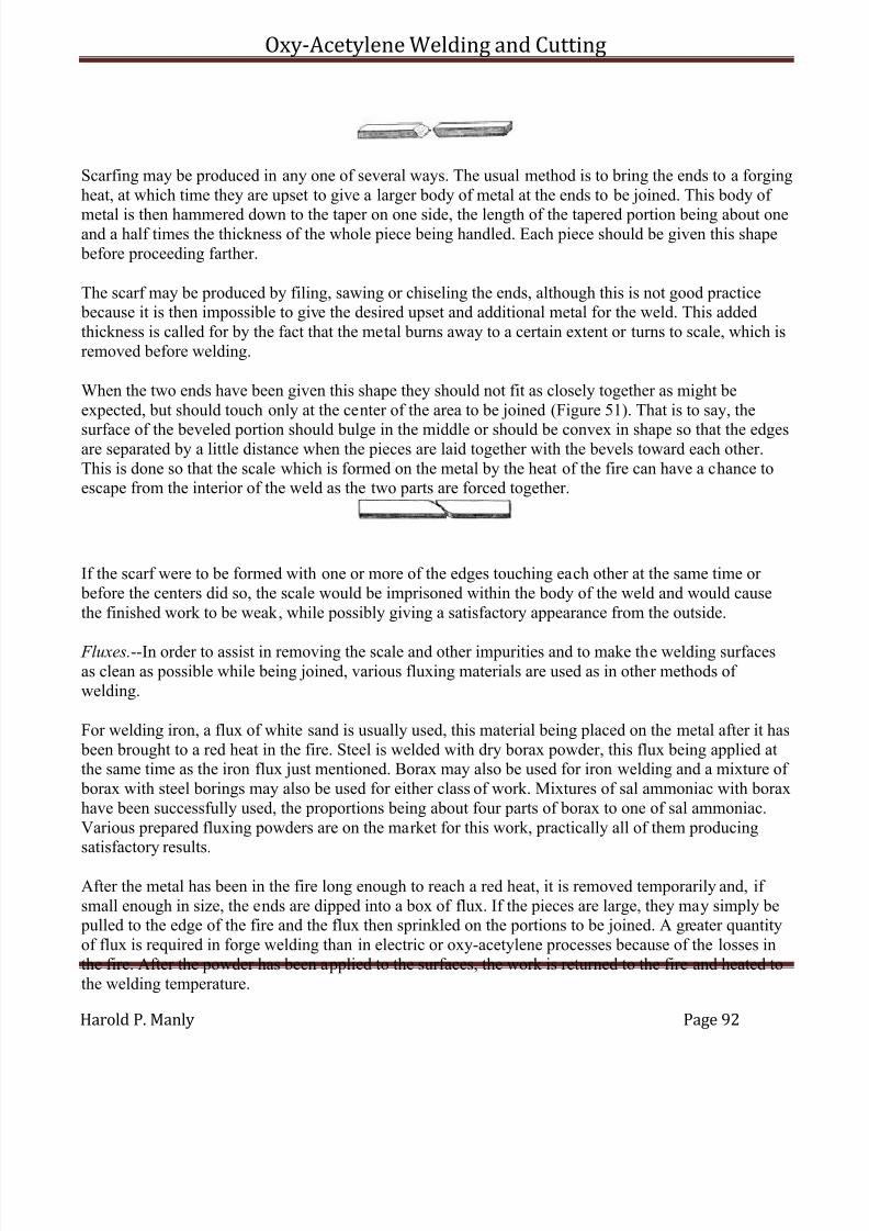
7/30/2019 Oxy Acetylene Welding and Cutting
http://slidepdf.com/reader/full/oxy-acetylene-welding-and-cutting 92/106
Oxy-Acetylene Welding and Cutting
Harold P. Manly Page 92
Scarfing may be produced in any one of several ways. The usual method is to bring the ends to a forgingheat, at which time they are upset to give a larger body of metal at the ends to be joined. This body of
metal is then hammered down to the taper on one side, the length of the tapered portion being about oneand a half times the thickness of the whole piece being handled. Each piece should be given this shape before proceeding farther.
The scarf may be produced by filing, sawing or chiseling the ends, although this is not good practice because it is then impossible to give the desired upset and additional metal for the weld. This addedthickness is called for by the fact that the metal burns away to a certain extent or turns to scale, which isremoved before welding.
When the two ends have been given this shape they should not fit as closely together as might beexpected, but should touch only at the center of the area to be joined (Figure 51). That is to say, the
surface of the beveled portion should bulge in the middle or should be convex in shape so that the edgesare separated by a little distance when the pieces are laid together with the bevels toward each other.This is done so that the scale which is formed on the metal by the heat of the fire can have a chance toescape from the interior of the weld as the two parts are forced together.
If the scarf were to be formed with one or more of the edges touching each other at the same time or before the centers did so, the scale would be imprisoned within the body of the weld and would causethe finished work to be weak, while possibly giving a satisfactory appearance from the outside.
Fluxes.--In order to assist in removing the scale and other impurities and to make the welding surfacesas clean as possible while being joined, various fluxing materials are used as in other methods of welding.
For welding iron, a flux of white sand is usually used, this material being placed on the metal after it has been brought to a red heat in the fire. Steel is welded with dry borax powder, this flux being applied atthe same time as the iron flux just mentioned. Borax may also be used for iron welding and a mixture of borax with steel borings may also be used for either class of work. Mixtures of sal ammoniac with boraxhave been successfully used, the proportions being about four parts of borax to one of sal ammoniac.Various prepared fluxing powders are on the market for this work, practically all of them producingsatisfactory results.
After the metal has been in the fire long enough to reach a red heat, it is removed temporarily and, if small enough in size, the ends are dipped into a box of flux. If the pieces are large, they may simply be pulled to the edge of the fire and the flux then sprinkled on the portions to be joined. A greater quantityof flux is required in forge welding than in electric or oxy-acetylene processes because of the losses inthe fire. After the powder has been applied to the surfaces, the work is returned to the fire and heated tothe welding temperature.

7/30/2019 Oxy Acetylene Welding and Cutting
http://slidepdf.com/reader/full/oxy-acetylene-welding-and-cutting 93/106
Oxy-Acetylene Welding and Cutting
Harold P. Manly Page 93
Heating the Work.--After being scarfed, the two pieces to be welded are placed in the fire and brought tothe correct temperature. This temperature can only be recognized by experiment and experience. Themetal must be just below that point at which small sparks begin to be thrown out of the fire andnaturally this is a hard point to distinguish. At the welding heat the metal is almost ready to flow and is
about the consistency of putty. Against the background of the fire and coal the color appears to be acream or very light yellow and the work feels soft as it is handled.
It is absolutely necessary that both parts be heated uniformly and so that they reach the weldingtemperature at the same time. For this reason they should be as close together in the fire as possible andside by side. When removed to be hammered together, time is saved if they are picked up in such a waythat when laid together naturally the beveled surfaces come together. This makes it necessary that theworkman remember whether the scarfed side is up or down, and to assist in this it is a good thing tomark the scarfed side with chalk or in some other noticeable manner, so that no mistake will be made inthe hurry of placing the work on the anvil.
The common practice in heating allows the temperature to rise until the small white sparks are seen tocome from the fire. Any heating above this point will surely result in burning that will ruin the iron or steel being handled. The best welding heat can be discerned by the appearance of the metal and its color after experience has been gained with this particular material. Test welds can be made and then broken,if possible, so that the strength gained through different degrees of heat can be known before attemptingmore important work.
Welding.--When the work has reached the welding temperature after having been replaced in the firewith the flux applied, the two parts are quickly tapped to remove the loose scale from their surfaces.They are then immediately laid across the top of the anvil, being placed in a diagonal position if both pieces are straight. The lower piece is rested on the anvil first with the scarf turned up and ready to
receive the top piece in the position desired. The second piece must be laid in exactly the position it is tofinally occupy because the two parts will stick together as soon as they touch and they cannot well bemoved after having once been allowed to come in contact with each other. This part of the work must bedone without any unnecessary loss of time because the comparatively low heat at which the parts weldallows them to cool below the working temperature in a few seconds.
The greatest difficulty will be experienced in withdrawing the metal from the fire before it becomes burned and in getting it joined before it cools below this critical point. The beveled edges of the scarf are, of course, the first parts to cool and the weld must be made before they reach a point at which theywill not join, or else the work will be defective in appearance and in fact.
If the parts being handled are of such a shape that there is danger of bending a portion back of the weld,this part may be cooled by quickly dipping it into water before laying the work on the anvil to be joined.
The workman uses a heavy hand hammer in making the joint, and his helper, if one is employed, uses asledge. With the two parts of the work in place on the anvil, the workman strikes several light blows, thefirst ones being at a point directly over the center of the weld, so that the joint will start from this pointand be worked toward the edges. After the pieces have united the helper strikes alternate blows with his
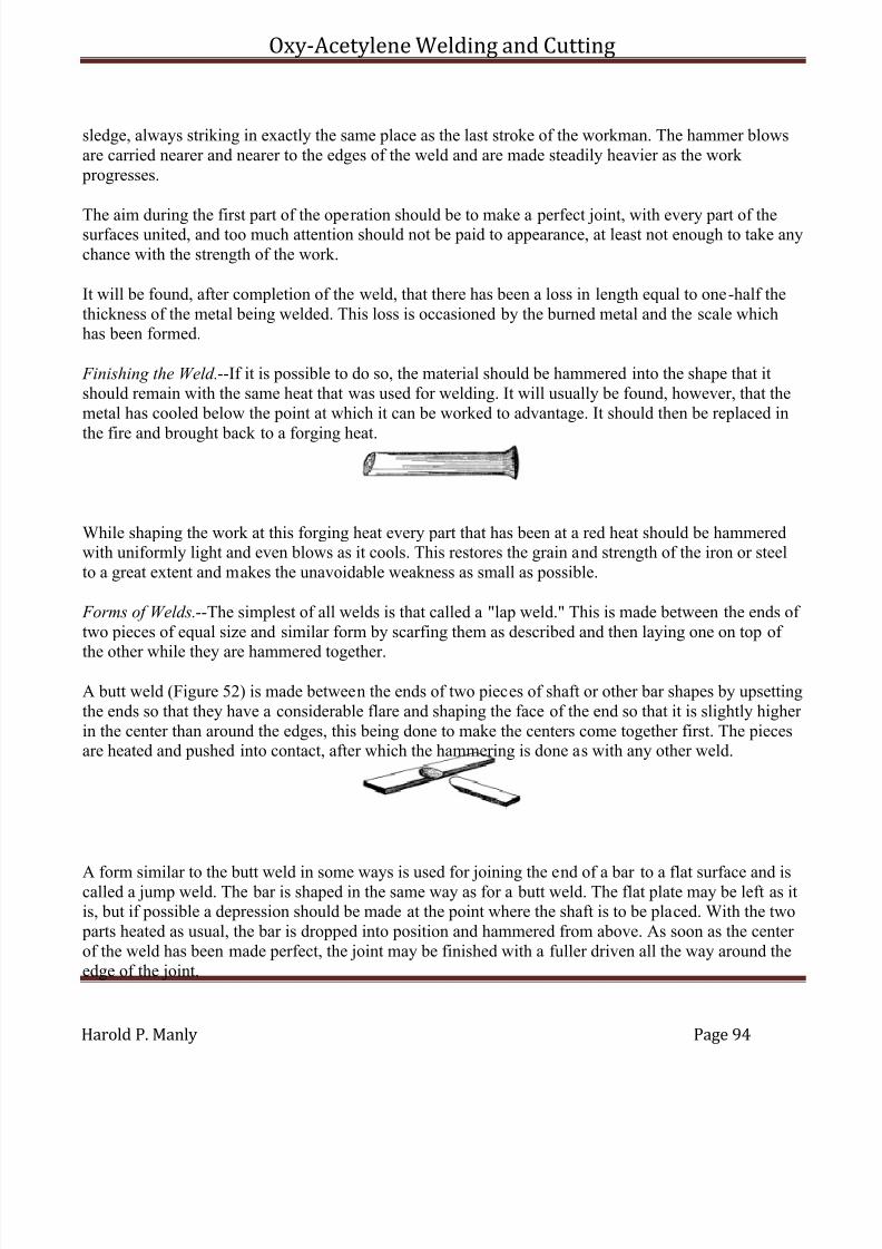
7/30/2019 Oxy Acetylene Welding and Cutting
http://slidepdf.com/reader/full/oxy-acetylene-welding-and-cutting 94/106
Oxy-Acetylene Welding and Cutting
Harold P. Manly Page 94
sledge, always striking in exactly the same place as the last stroke of the workman. The hammer blowsare carried nearer and nearer to the edges of the weld and are made steadily heavier as the work progresses.
The aim during the first part of the operation should be to make a perfect joint, with every part of thesurfaces united, and too much attention should not be paid to appearance, at least not enough to take anychance with the strength of the work.
It will be found, after completion of the weld, that there has been a loss in length equal to one-half thethickness of the metal being welded. This loss is occasioned by the burned metal and the scale whichhas been formed.
Finishing the Weld.--If it is possible to do so, the material should be hammered into the shape that itshould remain with the same heat that was used for welding. It will usually be found, however, that themetal has cooled below the point at which it can be worked to advantage. It should then be replaced in
the fire and brought back to a forging heat.
While shaping the work at this forging heat every part that has been at a red heat should be hammeredwith uniformly light and even blows as it cools. This restores the grain and strength of the iron or steelto a great extent and makes the unavoidable weakness as small as possible.
Forms of Welds.--The simplest of all welds is that called a "lap weld." This is made between the ends of two pieces of equal size and similar form by scarfing them as described and then laying one on top of
the other while they are hammered together.
A butt weld (Figure 52) is made between the ends of two pieces of shaft or other bar shapes by upsettingthe ends so that they have a considerable flare and shaping the face of the end so that it is slightly higher in the center than around the edges, this being done to make the centers come together first. The piecesare heated and pushed into contact, after which the hammering is done as with any other weld.
A form similar to the butt weld in some ways is used for joining the end of a bar to a flat surface and iscalled a jump weld. The bar is shaped in the same way as for a butt weld. The flat plate may be left as itis, but if possible a depression should be made at the point where the shaft is to be placed. With the two parts heated as usual, the bar is dropped into position and hammered from above. As soon as the center of the weld has been made perfect, the joint may be finished with a fuller driven all the way around theedge of the joint.
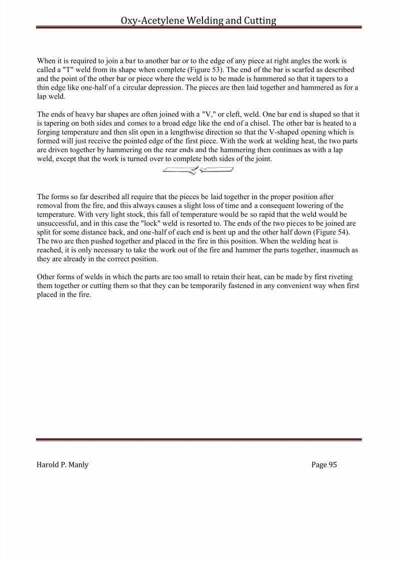
7/30/2019 Oxy Acetylene Welding and Cutting
http://slidepdf.com/reader/full/oxy-acetylene-welding-and-cutting 95/106
Oxy-Acetylene Welding and Cutting
Harold P. Manly Page 95
When it is required to join a bar to another bar or to the edge of any piece at right angles the work iscalled a "T" weld from its shape when complete (Figure 53). The end of the bar is scarfed as describedand the point of the other bar or piece where the weld is to be made is hammered so that it tapers to athin edge like one-half of a circular depression. The pieces are then laid together and hammered as for a
lap weld.
The ends of heavy bar shapes are often joined with a "V," or cleft, weld. One bar end is shaped so that itis tapering on both sides and comes to a broad edge like the end of a chisel. The other bar is heated to aforging temperature and then slit open in a lengthwise direction so that the V-shaped opening which isformed will just receive the pointed edge of the first piece. With the work at welding heat, the two partsare driven together by hammering on the rear ends and the hammering then continues as with a lapweld, except that the work is turned over to complete both sides of the joint.
The forms so far described all require that the pieces be laid together in the proper position after removal from the fire, and this always causes a slight loss of time and a consequent lowering of thetemperature. With very light stock, this fall of temperature would be so rapid that the weld would beunsuccessful, and in this case the "lock" weld is resorted to. The ends of the two pieces to be joined aresplit for some distance back, and one-half of each end is bent up and the other half down (Figure 54).The two are then pushed together and placed in the fire in this position. When the welding heat isreached, it is only necessary to take the work out of the fire and hammer the parts together, inasmuch asthey are already in the correct position.
Other forms of welds in which the parts are too small to retain their heat, can be made by first rivetingthem together or cutting them so that they can be temporarily fastened in any convenient way when first
placed in the fire.
7/30/2019 Oxy Acetylene Welding and Cutting
http://slidepdf.com/reader/full/oxy-acetylene-welding-and-cutting 96/106
Oxy-Acetylene Welding and Cutting
Harold P. Manly Page 96
CHAPTER VIII
SOLDERING, BRAZING AND THERMIT WELDING
SOLDERING
Common solder is an alloy of one-half lead with one-half tin, and is called "half and half." Hard solder is made with two-thirds tin and one-third lead. These alloys, when heated, are used to join surfaces of the same or dissimilar metals such as copper, brass, lead, galvanized iron, zinc, tinned plate, etc. Thesemetals are easily joined, but the action of solder with iron, steel and aluminum is not so satisfactory andrequires greater care and skill.
The solder is caused to make a perfect union with the surfaces treated with the help of heat from asoldering iron. The soldering iron is made from a piece of copper, pointed at one end and with the other
end attached to an iron rod and wooden handle. A flux is used to remove impurities from the joint andallow the solder to secure a firm union with the metal surface. The iron, and in many cases the work, isheated with a gasoline blow torch, a small gas furnace, an electric heater or an acetylene and air torch.
The gasoline torch which is most commonly used should be filled two-thirds full of gasoline through thehole in the bottom, which is closed by a screw plug. After working the small hand pump for 10 to 20strokes, hold the palm of your hand over the end of the large iron tube on top of the torch and open thegasoline needle valve about a half turn. Hold the torch so that the liquid runs down into the cup belowthe tube and fills it. Shut the gasoline needle valve, wipe the hands dry, and set fire to the fuel in thecup. Just as the gasoline fire goes out, open the gasoline needle valve about a half turn and hold alighted match at the end of the iron tube to ignite the mixture of vaporized gasoline and air. Open or close the needle valve to secure a flame about 4 inches long.
On top of the iron tube from which the flame issues there is a rest for supporting the soldering iron withthe copper part in the flame. Place the iron in the flame and allow it to remain until the copper becomesvery hot, not quite red, but almost so.
A new soldering iron or one that has been misused will have to be "tinned" before using. To do this,take the iron from the fire while very hot and rub the tip on some flux or dip it into soldering acid. Thenrub the tip of the iron on a stick of solder or rub the solder on the iron. If the solder melts off the stick without coating the end of the iron, allow a few drops to fall on a piece of tin plate, then nil the end of the iron on the tin plate with considerable force. Alternately rub the iron on the solder and dip into fluxuntil the tip has a coating of bright solder for about half an inch from the end. If the iron is in very badshape, it may be necessary to scrape or file the end before dipping in the flux for the first time. After theend of the iron is tinned in this way, replace it on the rest of the torch so that the tinned point is notdirectly in the flame, turning the flame down to accomplish this.
Flux.--The commonest flux, which is called "soldering acid," is made by placing pieces of zinc inmuriatic (hydrochloric) acid contained in a heavy glass or porcelain dish. There will be bubbles and
7/30/2019 Oxy Acetylene Welding and Cutting
http://slidepdf.com/reader/full/oxy-acetylene-welding-and-cutting 97/106
Oxy-Acetylene Welding and Cutting
Harold P. Manly Page 97
considerable heat evolved and zinc should be added until this action ceases and the zinc remains in theliquid, which is now chloride of zinc.
This soldering acid may be used on any metal to be soldered by applying with a brush or swab. For
electrical work, this acid should be made neutral by the addition of one part ammonia and one part water to each three parts of the acid. This neutralized flux will not corrode metal as will the ordinary acid.
Powdered resin makes a good flux for lead, tin plate, galvanized iron and aluminum. Tallow, olive oil, beeswax and vaseline are also used for this purpose. Muriatic acid may be used for zinc or galvanizediron without the addition of the zinc, as described in making zinc chloride. The addition of two heapingteaspoonfuls of sal ammoniac to each pint of the chloride of zinc is sometimes found to improve itsaction.
Soldering Metal Parts.--All surfaces to be joined should be fitted to each other as accurately as possibleand then thoroughly cleaned with a file, emery cloth, scratch bush or by dipping in lye. Work may be
cleaned by dipping it into nitric acid which has been diluted with an equal volume of water. The work should be heated as hot as possible without danger of melting, as this causes the solder to flow better and secure a much better hold on the surfaces. Hard solder gives better results than half and half, but ismore difficult to work. It is very important that the soldering iron be kept at a high heat during all work,otherwise the solder will only stick to the surfaces and will not join with them.
Sweating is a form of soldering in which the surfaces of the work are first covered with a thin layer of solder by rubbing them with the hot iron after it has been dipped in or touched to the soldering stick.These surfaces are then placed in contact and heated to a point at which the solder melts and unites.Sweating is much to be preferred to ordinary soldering where the form of the work permits it. This is theonly method which should ever be used when a fitting is to be placed over the end of a length of tube.
Soldering Holes.--Clean the surfaces for some distance around the hole until they are bright, and applyflux while holding the hot iron near the hole. Touch the tip of the iron to some solder until the solder is picked up on the iron, and then place this solder, which was just picked up, around the edge of the hole.It will leave the soldering iron and stick to the metal. Keep adding solder in this way until the hole has been closed up by working from the edges and building toward the center. After the hole is closed,apply more flux to the job and smooth over with the hot iron until there are no rough spots. Should thesolder refuse to flow smoothly, the iron is not hot enough.
Soldering Seams.--Clean back from the seam or split for at least half an inch all around and then buildup the solder in the same way as was done with the hole. After closing the opening, apply more flux to
the work and run the hot iron lengthwise to smooth the job.
Soldering Wires.--Clean all insulation from the ends to be soldered and scrape the ends bright. Lay theends parallel to each other and, starting at the middle of the cleaned portion, wrap the ends around eachother, one being wrapped to the right, the other to the left. Hold the hot iron under the twisted joint andapply flux to the wire. Then dip the iron in the solder and apply to the twisted portion until the spaces between the wires are filled with solder. Finish by smoothing the joint and cleaning away all excess
7/30/2019 Oxy Acetylene Welding and Cutting
http://slidepdf.com/reader/full/oxy-acetylene-welding-and-cutting 98/106
Oxy-Acetylene Welding and Cutting
Harold P. Manly Page 98
metal by rubbing the hot iron lengthwise. The joint should now be covered with a layer of rubber tapeand this covered with a layer of ordinary friction tape.
Steel and Iron.--Steel surfaces should be cleaned, then covered with clear muriatic acid. While the acid
is on the metal, rub with a stick of zinc and then tin the surfaces with the hot iron as directed. Cast ironshould be cleaned and dipped in strong lye to remove grease. Wash the lye away with clean water andcover with muriatic acid as with steel. Then rub with a piece of zinc and tin the surfaces by using resinas a flux.
It is very difficult to solder aluminum with ordinary solder. A special aluminum solder should besecured, which is easily applied and makes a strong joint. Zinc or phosphor tin may be used in place of ordinary solder to tin the surfaces or to fill small holes or cracks. The aluminum must be thoroughlyheated before attempting to solder and the flux may be either resin or soldering acid. The aluminummust be thoroughly cleaned with dilute nitric acid and kept hot while the solder is applied by forciblerubbing with the hot iron.
BRAZING
This is a process for joining metal parts, very similar to soldering, except that brass is used to make the joint in place of the lead and zinc alloys which form solder. Brazing must not be attempted on metalswhose melting point is less than that of sheet brass.
Two pieces of brass to be brazed together are heated to a temperature at which the brass used in the process will melt and flow between the surfaces. The brass amalgamates with the surfaces and makes avery strong and perfect joint, which is far superior to any form of soldering where the work allows this process to be used, and in many cases is the equal of welding for the particular field in which it applies.
Brazing Heat and Tools.--The metal commonly used for brazing will melt at heats between 1350° and1650° Fahrenheit. To bring the parts to this temperature, various methods are in use, using solid, liquidor gaseous fuels. While brazing may be accomplished with the fire of the blacksmith forge, this methodis seldom satisfactory because of the difficulty of making a sufficiently clean fire with smithing coal,and it should not be used when anything else is available. Large jobs of brazing may be handled with acharcoal fire built in the forge, as this fuel produces a very satisfactory and clean fire. The onlyobjection is in the difficulty of confining the heat to the desired parts of the work.
The most satisfactory fire is that from a fuel gas torch built for this work. These torches are simplyforms of Bunsen burners, mixing the proper quantity of air with the gas to bring about a perfect
combustion. Hose lines lead to the mixing tube of the gas torch, one line carrying the gas and the other air under a moderate pressure. The air line is often dispensed with, allowing the gas to draw air into the burner on the injector principle, much the same as with illuminating gas burners for use withincandescent mantles. Valves are provided with which the operator may regulate the amount of both gasand air, and ordinarily the quality and intensity of the flame.

7/30/2019 Oxy Acetylene Welding and Cutting
http://slidepdf.com/reader/full/oxy-acetylene-welding-and-cutting 99/106
Oxy-Acetylene Welding and Cutting
Harold P. Manly Page 99
When gas is not available, recourse may be had to the gasoline torch made for brazing. This torch is built in the same way as the small portable gasoline torches for soldering operations, with the exceptionthat two regulating needle valves are incorporated in place of only one.
The torches are carried on a framework, which also supports the work being handled. Fuel is forced tothe torch from a large tank of gasoline into which air pressure is pumped by hand. The torches areregulated to give the desired flame by means of the needle valves in much the same way as with anyother form of pressure torch using liquid fuel.
Another very satisfactory form of torch for brazing is the acetylene-air combination described in thechapter on welding instruments. This torch gives the correct degree of heat and may be regulated to givea clean and easily controlled flame.
Regardless of the source of heat, the fire or flame must be adjusted so that no soot is deposited on themetal surfaces of the work. This can only be accomplished by supplying the exact amounts of gas and
air that will produce a complete burning of the fuel. With the brazing torches in common use two headsare furnished, being supplied from the same source of fuel, but with separate regulating devices. Thetorches are adjustably mounted in such a way that the flames may be directed toward each other, heatingtwo sides of the work at the same time and allowing the pieces to be completely surrounded with theflame.
Except for the source of heat, but one tool is required for ordinary brazing operations, this being aspatula formed by flattening one end of a quarter-inch steel rod. The spatula is used for placing the brazing metal on the work and for handling the flux that is required in this work as in all other similar operations.
Spelter.--The metal that is melted into the joint is called spelter. While this name originally applied to but one particular grade or composition of metal, common use has extended the meaning until it isgenerally applied to all grades.
Spelter is variously composed of alloys containing copper, zinc, tin and antimony, the mixtureemployed depending on the work to be done. The different grades are of varying hardness, the harder kinds melting at higher temperatures than the soft ones and producing a stronger joint when used. Thereason for not using hard spelter in all cases is the increased difficulty of working it and the fact that itsmelting point is so near to some of the metals brazed that there is great danger of melting the work aswell as the spelter.
The hardest grade of spelter is made from three-fourths copper with one-fourth zinc and is used for working on malleable and cast iron and for steel.
This hard spelter melts at about 1650° and is correspondingly difficult to handle.
A spelter suitable for working with copper is made from equal parts of copper and zinc, melting at about1400° Fahrenheit, 500° below the melting point of the copper itself. A still softer brazing metal is
7/30/2019 Oxy Acetylene Welding and Cutting
http://slidepdf.com/reader/full/oxy-acetylene-welding-and-cutting 100/106
Oxy-Acetylene Welding and Cutting
Harold P. Manly Page 100
composed of half copper, three-eighths zinc and one-eighth tin. This grade is used for fastening brass toiron and copper and for working with large pieces of brass to brass. For brazing thin sheet brass andlight brass castings, a metal is used which contains two-thirds tin and one-third antimony. The lowmelting point of this last composition makes it very easy to work with and the danger of melting the
work is very slight. However, as might be expected, a comparatively weak joint is secured, which willnot stand any great strain.
All of the above brazing metals are used in powder form so that they may be applied with the spatulawhere the joint is exposed on the outside of the work. In case it is necessary to braze on the inside of atube or any deep recess, the spelter may be placed on a flat rod long enough to reach to the farthest point. By distributing the spelter at the proper points along the rod it may be placed at the right points byturning the rod over after inserting into the recess.
Flux.--In order to remove the oxides produced under brazing heat and to allow the brazing metal to flowfreely into place, a flux of some kind must be used. The commonest flux is simply a pure calcined borax
powder, that is, a borax powder that has been heated until practically all the water has been driven off.
Calcined borax may also be mixed with about 15 per cent of sal ammoniac to make a satisfactoryfluxing powder. It is absolutely necessary to use flux of some kind and a part of whatever is used should be made into a paste with water so that it can be applied to the joint to be brazed before heating. Theremainder of the powder should be kept dry for use during the operation and after the heat has beenapplied.
Preparing the Work.--The surfaces to be brazed are first thoroughly cleaned with files, emery cloth or sand paper. If the work is greasy, it should be dipped into a bath of lye or hot soda water so that all traceof oil is removed. The parts are then placed in the relation to each other that they are to occupy when the
work has been completed. The edges to be joined should make a secure and tight fit, and should matcheach other at all points so that the smallest possible space is left between them. This fit should not be sotight that it is necessary to force the work into place, neither should it be loose enough to allow anyconsiderable space between the surfaces. The molten spelter will penetrate between surfaces that water will flow between when the work and spelter have both been brought to the proper heat. It is, of course,necessary that the two parts have a sufficient number of points of contact so that they will remain in the proper relative position.
The work is placed on the surface of the brazing table in such a position that the flame from the torcheswill strike the parts to be heated, and with the joint in such a position that the melted spelter will flowdown through it and fill every possible part of the space between the surfaces under the action of
gravity. That means that the edge of the joint must be uppermost and the crack to be filled must not liehorizontal, but at the greatest slant possible. Better than any degree of slant would be to have the line of the joint vertical.
The work is braced up or clamped in the proper position before commencing to braze, and it is best to place fire brick in such positions that it will be impossible for cooling draughts of air to reach the heatedmetal should the flame be removed temporarily during the process. In case there is a large body of iron,
7/30/2019 Oxy Acetylene Welding and Cutting
http://slidepdf.com/reader/full/oxy-acetylene-welding-and-cutting 101/106
Oxy-Acetylene Welding and Cutting
Harold P. Manly Page 101
steel or copper to be handled, it is often advisable to place charcoal around the work, igniting this withthe flame of the torch before starting to braze so that the metal will be maintained at the correct heatwithout depending entirely on the torch.
When handling brass pieces having thin sections there is danger of melting the brass and causing it toflow away from under the flame, with the result that the work is ruined. If, in the judgment of theworkman, this may happen with the particular job in hand, it is well to build up a mould of fire clay back of the thin parts or preferably back of the whole piece, so that the metal will have the necessarysupport. This mould may be made by mixing the fire clay into a stiff paste with water and then packingit against the piece to be supported tightly enough so that the form will be retained even if the metalsoftens.
Brazing.--With the work in place, it should be well covered with the paste of flux and water, then heateduntil this flux boils up and runs over the surfaces. Spelter is then placed in such a position that it will runinto the joint and the heat is continued or increased until the spelter melts and flows in between the two
surfaces. The flame should surround the work during the heating so that outside air is excluded as far asis possible to prevent excessive oxidization.
When handling brass or copper, the flame should not be directed so that its center strikes the metalsquarely, but so that it glances from one side or the other. Directing the flame straight against the work is often the cause of melting the pieces before the operation is completed. When brazing two differentmetals, the flame should play only on the one that melts at the higher temperature, the lower melting part receiving its heat from the other. This avoids the danger of melting one before the other reaches the brazing point.
The heat should be continued only long enough to cause the spelter to flow into place and no longer.
Prolonged heating of any metal can do nothing but oxidize and weaken it, and this practice should beavoided as much as possible. If the spelter melts into small globules in place of flowing, it may becaused to spread and run into the joint by lightly tapping the work. More dry flux may be added with thespatula if the tapping does not produce the desired result.
Excessive use of flux, especially toward the end of the work, will result in a very hard surface on all thework, a surface which will be extremely difficult to finish properly. This trouble will be present to acertain extent anyway, but it may be lessened by a vigorous scraping with a wire brush just as soon asthe work is removed from the fire. If allowed to cool before cleaning, the final appearance will not be asgood as with the surplus metal and scale removed immediately upon completing the job.
After the work has been cleaned with the brush it may be allowed to cool and finished to the desiredshape, size and surface by filing and polishing. When filed, a very thin line of brass should appear where the crack was at the beginning of the work. If it is desired to avoid a square shoulder and fill in anangle joint to make it rounding, the filling is best accomplished by winding a coil of very thin brass wirearound the part of the work that projects and then causing this to flow itself or else allow the spelter tofill the spaces between the layers of wire. Copper wire may also be used for this purpose, the spaces being filled with melted spelter.
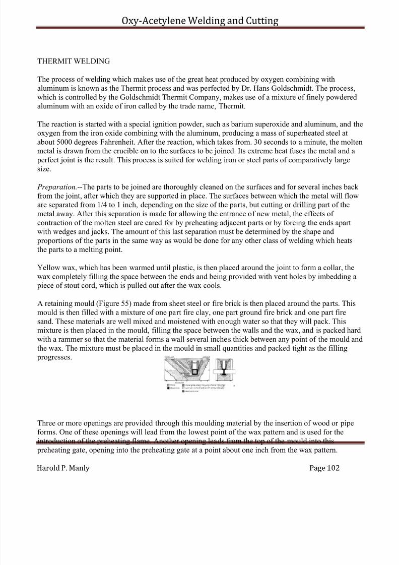
7/30/2019 Oxy Acetylene Welding and Cutting
http://slidepdf.com/reader/full/oxy-acetylene-welding-and-cutting 102/106
Oxy-Acetylene Welding and Cutting
Harold P. Manly Page 102
THERMIT WELDING
The process of welding which makes use of the great heat produced by oxygen combining withaluminum is known as the Thermit process and was perfected by Dr. Hans Goldschmidt. The process,
which is controlled by the Goldschmidt Thermit Company, makes use of a mixture of finely powderedaluminum with an oxide of iron called by the trade name, Thermit.
The reaction is started with a special ignition powder, such as barium superoxide and aluminum, and theoxygen from the iron oxide combining with the aluminum, producing a mass of superheated steel atabout 5000 degrees Fahrenheit. After the reaction, which takes from. 30 seconds to a minute, the moltenmetal is drawn from the crucible on to the surfaces to be joined. Its extreme heat fuses the metal and a perfect joint is the result. This process is suited for welding iron or steel parts of comparatively largesize.
Preparation.--The parts to be joined are thoroughly cleaned on the surfaces and for several inches back
from the joint, after which they are supported in place. The surfaces between which the metal will floware separated from 1/4 to 1 inch, depending on the size of the parts, but cutting or drilling part of themetal away. After this separation is made for allowing the entrance of new metal, the effects of contraction of the molten steel are cared for by preheating adjacent parts or by forcing the ends apartwith wedges and jacks. The amount of this last separation must be determined by the shape and proportions of the parts in the same way as would be done for any other class of welding which heatsthe parts to a melting point.
Yellow wax, which has been warmed until plastic, is then placed around the joint to form a collar, thewax completely filling the space between the ends and being provided with vent holes by imbedding a piece of stout cord, which is pulled out after the wax cools.
A retaining mould (Figure 55) made from sheet steel or fire brick is then placed around the parts. Thismould is then filled with a mixture of one part fire clay, one part ground fire brick and one part firesand. These materials are well mixed and moistened with enough water so that they will pack. Thismixture is then placed in the mould, filling the space between the walls and the wax, and is packed hardwith a rammer so that the material forms a wall several inches thick between any point of the mould andthe wax. The mixture must be placed in the mould in small quantities and packed tight as the filling progresses.
Three or more openings are provided through this moulding material by the insertion of wood or pipeforms. One of these openings will lead from the lowest point of the wax pattern and is used for theintroduction of the preheating flame. Another opening leads from the top of the mould into this preheating gate, opening into the preheating gate at a point about one inch from the wax pattern.
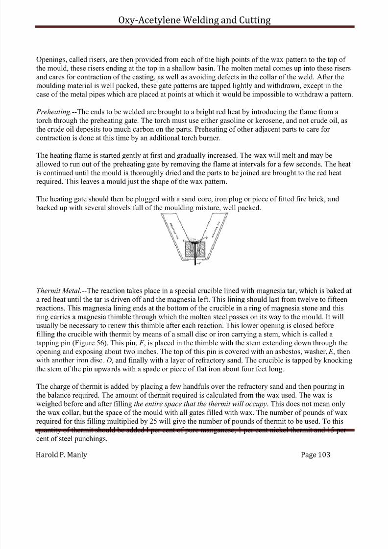
7/30/2019 Oxy Acetylene Welding and Cutting
http://slidepdf.com/reader/full/oxy-acetylene-welding-and-cutting 103/106
Oxy-Acetylene Welding and Cutting
Harold P. Manly Page 103
Openings, called risers, are then provided from each of the high points of the wax pattern to the top of the mould, these risers ending at the top in a shallow basin. The molten metal comes up into these risersand cares for contraction of the casting, as well as avoiding defects in the collar of the weld. After themoulding material is well packed, these gate patterns are tapped lightly and withdrawn, except in the
case of the metal pipes which are placed at points at which it would be impossible to withdraw a pattern.
Preheating.--The ends to be welded are brought to a bright red heat by introducing the flame from atorch through the preheating gate. The torch must use either gasoline or kerosene, and not crude oil, asthe crude oil deposits too much carbon on the parts. Preheating of other adjacent parts to care for contraction is done at this time by an additional torch burner.
The heating flame is started gently at first and gradually increased. The wax will melt and may beallowed to run out of the preheating gate by removing the flame at intervals for a few seconds. The heatis continued until the mould is thoroughly dried and the parts to be joined are brought to the red heatrequired. This leaves a mould just the shape of the wax pattern.
The heating gate should then be plugged with a sand core, iron plug or piece of fitted fire brick, and backed up with several shovels full of the moulding mixture, well packed.
Thermit Metal.--The reaction takes place in a special crucible lined with magnesia tar, which is baked ata red heat until the tar is driven off and the magnesia left. This lining should last from twelve to fifteenreactions. This magnesia lining ends at the bottom of the crucible in a ring of magnesia stone and thisring carries a magnesia thimble through which the molten steel passes on its way to the mould. It willusually be necessary to renew this thimble after each reaction. This lower opening is closed beforefilling the crucible with thermit by means of a small disc or iron carrying a stem, which is called atapping pin (Figure 56). This pin, F , is placed in the thimble with the stem extending down through theopening and exposing about two inches. The top of this pin is covered with an asbestos, washer, E , thenwith another iron disc. D, and finally with a layer of refractory sand. The crucible is tapped by knockingthe stem of the pin upwards with a spade or piece of flat iron about four feet long.
The charge of thermit is added by placing a few handfuls over the refractory sand and then pouring inthe balance required. The amount of thermit required is calculated from the wax used. The wax isweighed before and after filling the entire space that the thermit will occupy. This does not mean onlythe wax collar, but the space of the mould with all gates filled with wax. The number of pounds of waxrequired for this filling multiplied by 25 will give the number of pounds of thermit to be used. To thisquantity of thermit should be added I per cent of pure manganese, 1 per cent nickel thermit and 15 per cent of steel punchings.
7/30/2019 Oxy Acetylene Welding and Cutting
http://slidepdf.com/reader/full/oxy-acetylene-welding-and-cutting 104/106
Oxy-Acetylene Welding and Cutting
Harold P. Manly Page 104
It is necessary, when more than 10 pounds of thermit will be used, to mix steel punchings not exceeding3/8 inch diameter by 1/8 inch thick with the powder in order to sufficiently retard the intensity of thereaction.
Half a teaspoonful of ignition powder is placed on top of the thermit charge and ignited with a stormmatch or piece of red hot iron. The cover should be immediately closed on the top of the crucible andthe operator should get away to a safe distance because of the metal that may be thrown out of thecrucible.
After allowing about 30 seconds to a minute for the reaction to take place and the slag to rise to the topof the crucible, the tapping pin is struck from below and the molten metal allowed to run into the mould.The mould should be allowed to remain in place as long as possible, preferably over night, so as toanneal the steel in the weld, but in no case should it be disturbed for several hours after pouring. After removing the mould, drill through the metal left in the riser and gates and knock these sections off. No part of the collar should be removed unless absolutely necessary.
7/30/2019 Oxy Acetylene Welding and Cutting
http://slidepdf.com/reader/full/oxy-acetylene-welding-and-cutting 105/106
Oxy-Acetylene Welding and Cutting
Harold P. Manly Page 105
CHAPTER IX
OXYGEN PROCESS FOR REMOVAL OF CARBON
Until recently the methods used for removing carbon deposits from gas engine cylinders were veryimpractical and unsatisfactory. The job meant dismantling the motor, tearing out all parts, and scrapingthe pistons and cylinder walls by hand.
The work was never done thoroughly. It required hours of time to do it, and then there was always thedanger of injuring the inside of the cylinders.
These methods have been to a large extent superseded by the use of oxygen under pressure. The variousdevices that are being manufactured are known as carbon removers, decarbonizers, etc., and largenumbers of them are in use in the automobile and gasoline traction motor industry.
Outfit.--The oxygen carbon cleaner consists of a high pressure oxygen cylinder with automatic reducingvalve, usually constructed on the diaphragm principle, thus assuring positive regulation of pressure.This valve is fitted with a pressure gauge, rubber hose, decarbonizing torch with shut off and flexibletube for insertion into the chamber from which the carbon is to be removed.
There should also be an asbestos swab for swabbing out the inside of the cylinder or other chamber withkerosene previous to starting the operation. The action consists in simply burning the carbon to a finedust in the presence of the stream of oxygen, this dust being then blown out.
Operation.--The following are instructions for operating the cleaner:--
(1) Close valve in gasoline supply line and start the motor, letting it run until the gasoline is exhausted.
(2) If the cylinders be T or L head, remove either the inlet or the exhaust valve cap, or a spark plug if thecap is tight. If the cylinders have overhead valves, remove a spark plug. If any spark plug is thenremaining in the cylinder it should be removed and an old one or an iron pipe plug substituted.
(3) Raise the piston of the cylinder first to be cleaned to the top of the compression stroke and continuethis from cylinder to cylinder as the work progresses.
(4) In motors where carbon has been burned hard, the cylinder interior should then be swabbed withkerosene before proceeding. Work the swab, saturated with kerosene, around the inside of the cylinder until all the carbon has been moistened with the oil. This same swab may be used to ignite the gas in thecylinder in place of using a match or taper.
(5) Make all connections to the oxygen cylinder.
(6) Insert the torch nozzle in the cylinder, open the torch valve gradually and regulate to about two lbs. pressure. Manipulate the nozzle inside the cylinder and light a match or other flame at the opening so

7/30/2019 Oxy Acetylene Welding and Cutting
http://slidepdf.com/reader/full/oxy-acetylene-welding-and-cutting 106/106
Oxy-Acetylene Welding and Cutting
that the carbon starts to burn. Cover the various points within the cylinder and when there is no further burning the carbon has been removed. The regulating and oxygen tank valves are operated in exactly thesame way as for welding as previously explained.
It should be carefully noted that when the piston is up, ready to start the operation, both valves must beclosed. There will be a considerable display of sparks while this operation is taking place, but they willnot set fire to the grease and oil. Care should be used to see that no gasoline is about.