Embed Size (px)
Citation preview
Tissue Oximeter
Operator’s Manual
ViOptix, Incorporated 39655 Eureka Drive Newark, CA 94560
Phone: 510-226-5860 Fax: 510-226-5864 Website: www.vioptix.com
About This Manual
Trademarks
T.Ox™ Tissue Oximeter is a registered trademark of ViOptix, Inc.
References
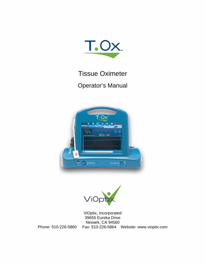
References to “ViOptix” in this manual shall imply ViOptix, Inc. The information in this manual has been carefully checked and is believed to be accurate. In the interest of continued product development, ViOptix reserves the right to make changes and improvements to this manual and the products it describes at any time, without notice or obligation. Caution: Federal law (US) restricts this device to sale by or on the order of a physician. Caution: Use of controls or adjustments or performance of procedures other than those specified herein may result in hazardous radiation exposure
Copyright 2003-2016 Covered by one or more of the following US Patents and foreign equivalents: www.vioptix.com/patents ViOptix, Incorporated 39655 Eureka Drive Newark, CA 94560 Tel: 510-226-5860 Fax: 510-226-5864 ViOptix part number for this Operator’s Manual: OXY-2-USM-1
VISIBLE AND INVISIBLE LASER RADIATION
AVOID DIRECT EYE EXPOSURE CLASS 3R LASER PRODUCT
690 nm and 830 nm, 3 mW max. IEC60825-1:1993+A1+A2
Operator’s Manual Page 3 of 79
OXY-2-USM-1, REV I
Table of Contents
Table of Tables ..................................................................................................................... 5
Table of Figures.................................................................................................................... 6
Section I. Introduction ......................................................................................................... 7 A. Overview ........................................................................................................................ 7
The ODIS Technology .................................................................................................. 7 B. Device Description ......................................................................................................... 8 C. Intended Use................................................................................................................... 8
Section II. Safety .................................................................................................................. 9 A. Contraindications, Warnings, and Cautions................................................................... 9
1. Contraindications ....................................................................................................... 9 2. Warnings .................................................................................................................... 9 3. Precautions .............................................................................................................. 10 4. Cautions ................................................................................................................... 10
Section III. System Setup .................................................................................................. 11 A. System Configuration .................................................................................................. 12
1. Connecting the T.Ox™ Tissue Oximeter ................................................................ 12 2. Turning on the T.Ox™ Tissue Oximeter ................................................................ 12
B. Using the T.Ox™ Tissue Oximeter Controls .............................................................. 12 1. AC Power Switch .................................................................................................... 12 2. ON/Standby Button ................................................................................................. 12 3. T.Ox™ Tissue Oximeter Monitor Screen Display .................................................. 13 4. Patch Sensor Probe Acquisition .............................................................................. 15 6. Recording Patient Data ............................................................................................ 16 7. Oops Save Discard .................................................................................................. 17
Section IV. System Operation ........................................................................................... 18 A. Site Preparation ............................................................................................................ 18 B. Data Acquisition........................................................................................................... 18
1. Understanding the Display Monitor Screen ............................................................ 18 2. Viewing the Main Screen ........................................................................................ 22 3. Understanding the StO2 Graph and Data ................................................................. 24 4. Understanding Signal Quality ................................................................................. 25 5. Setting Alarms ......................................................................................................... 28 6. Setting the StO2 Alarm ............................................................................................ 28 7. Reviewing Graphs and Data .................................................................................... 29 8. Reviewing StO2 Data ............................................................................................... 30 9. Reviewing Data ....................................................................................................... 32 10. Magnifying the StO2 View .................................................................................... 33 11. Viewing Numerics ................................................................................................. 35 12. Setting Parameters in the Setup Screen ................................................................. 37 13. Setting the Date and Time ..................................................................................... 38 14. Setting the Date ..................................................................................................... 40 15. Setting the Time Zone ........................................................................................... 41 16. Setting Up Auto Adjust for Daylight Saving Time ............................................... 43
Operator’s Manual Page 4 of 79
OXY-2-USM-1, REV I
17. Setting the Sound Level for Alarms ...................................................................... 44 18. Setting Peripherals (Printer) .................................................................................. 45 19. Performing Maintenance ....................................................................................... 46 20. Setting Up Organization Information .................................................................... 50 21. Open an Existing File for Review ......................................................................... 52 22. Recording a New File (Saving) ............................................................................. 53 23. Printing Data .......................................................................................................... 58 24. Reports ................................................................................................................... 61 25. Using the Help System .......................................................................................... 63
C. Device Failure and Recovery ....................................................................................... 64
Section V. Maintenance .................................................................................................... 67 Cleaning and Disinfecting: ............................................................................................... 67
Section VI. Specifications .................................................................................................. 68 Ranges and Precision: ....................................................................................................... 68 Glossary of Symbols ......................................................................................................... 70 Labels ................................................................................................................................ 72
Section VII. Troubleshooting ........................................................................................... 75
Operator’s Manual Page 5 of 79
OXY-2-USM-1, REV I
Table of Tables Table 1. Control Bar Buttons ............................................................................................... 20 Table 2. System Status Bar .................................................................................................. 21 Table 3. Buttons and Tabs on the Main Screen ................................................................... 24 Table 4. Percentage of Zoom ............................................................................................... 30 Table 5 Alarm Messages ..................................................................................................... 75 Table 6 Error Messages ...................................................................................................... 76 Table 7 Status Messages ..................................................................................................... 77 Table 8 Other Status, Error, and Warning Messages .......................................................... 78
Operator’s Manual Page 6 of 79
OXY-2-USM-1, REV I
Table of Figures Figure 1. Main Screen Functional Areas ............................................................................ 13 Figure 2. Oops Save Discard Screen.................................................................................. 17 Figure 3. Main Screen, with Control Bar at Top and System Status Bar at Bottom ........... 1 Figure 4. Main Screen ........................................................................................................ 22 Figure 5. Low Signal-Quality Alarm ................................................................................. 25 Figure 6. Low Signal Quality Suppresses StO2% Display ................................................ 26 Figure 7. Password-Based Override of Signal Quality Criterion ........................................ 27 Figure 8. StO2 Alarm Set Screen .......................................................................................... 28 Figure 9. Review StO2 Screen ............................................................................................. 29 Figure 10. Review Data Screen ........................................................................................... 32 Figure 11. Magnify StO2 Screen .......................................................................................... 33 Figure 12. View Numerics Screen ....................................................................................... 35 Figure 13. Setup Screen ....................................................................................................... 37 Figure 14. Set Up Current Date and Current Time Screen .................................................. 38 Figure 15. Set Up Current Time Screen ............................................................................... 39 Figure 16. Set Up Date Screen ............................................................................................. 40 Figure 17. Set Up Time Zone Screen 1 ................................................................................ 41 Figure 18. Set Up Time Zone Screen 2 ................................................................................ 42 Figure 19. Set Up Time Zone Screen 3 ................................................................................ 43 Figure 20. Set Up Sound Level of Alarms ........................................................................... 44 Figure 21. Set Up Peripherals Screen .................................................................................. 45 Figure 22. Maintenance Sensor Test Screen ........................................................................ 46 Figure 23. Maintenance Screen, Step 1 ............................................................................... 47 Figure 24. Maintenance Screen, Step 2 ............................................................................... 48 Figure 25. Maintenance Screen, Step 3 ............................................................................... 49 Figure 26. Organization Information ................................................................................... 50 Figure 27. Organization Information Confirmation............................................................. 51 Figure 28. Open File Screen ................................................................................................ 52 Figure 29. Oops Save Discard Screen, Step 1 ..................................................................... 53 Figure 30. Save File Screen ................................................................................................. 54 Figure 31. Duplicate Filename Screen ................................................................................. 55 Figure 32. Free Disk Space for File Save Screen ................................................................ 56 Figure 33. Discard Confirmation Screen ............................................................................. 57 Figure 34. Print File Screen ................................................................................................. 58 Figure 35. StO2 Print Screen Report .................................................................................... 61 Figure 36. Print Summary Report ........................................................................................ 62 Figure 37. Help Index .......................................................................................................... 63 Figure 38. Reboot Recovery Screen .................................................................................... 65 Figure 39. Sensor Data Disposal .......................................................................................... 66

Operator’s Manual Page 7 of 79
OXY-2-USM-1, REV I
Section I. Introduction
A. Overview The T.Ox™ Tissue Oximeter is an optically based device that non-invasively estimates the percent oxygen saturation (StO2%) in a volume of tissue underneath the sensor. T.Ox™ Tissue Oximeter measurements are based on its proprietary technology called ODIS. (See “The ODIS Technology” section, below.) The T.Ox™ Tissue Oximeter works by emitting two different wavelengths of near-infrared (NIR) light into tissue at depths of 0–10 mm. The light is transmitted to the tissue by two light sources, and collected by four photo detectors in each sensor. As the light is collected and measured, the absorption and scattering coefficients of the tissue are calculated. Each tissue component has a unique absorption spectrum or light “signature”. The T.Ox™ Tissue Oximeter uses two wavelengths (690 and 830 nm) of near-infrared light specific to oxyhemoglobin (HbO2) and deoxyhemoglobin (Hb) for the noninvasive real-time measurements of StO2.
The ODIS Technology Optical Diffusion Imaging Spectroscopy (ODIS) is a non-invasive tissue characterization method based on measurement of reflectance or transmittance of near-infrared light shed onto tissue surface. In biological tissue, near-infrared light is highly scattered and moderately absorbed. This allows photons to travel up to one meter in tissue, in a random walk fashion, before being absorbed. Diffuse optical imaging is achieved by sending various optical signals to various locations of tissue and measuring the corresponding diffuse reflectance or transmittance on tissue surface. ViOptix has developed special source-detector patterns and algorithms, which make the measurements accurate, real-time and insensitive to external factors. The system’s self-calibrating approach makes it possible to perform imaging and spectroscopy without a baseline data set. This is particularly important in saving exam time.
Operator’s Manual Page 8 of 79
OXY-2-USM-1, REV I
B. Device Description The T.Ox™ Tissue Oximeter is a lightweight and portable, AC power–operated, unit with a 30-minute, lithium-ion battery backup. The console has a color LCD display monitor, a standard one sampling channel (with a two-channel option), and up to two fiber optic sensors. It has adjustable audible and visual alarms for: StO2 low and high alarm limits Low battery The T.Ox™ Tissue Oximeter has visual alarms for: Audio muted Sensor laser ON AC power OFF Low Battery The T.Ox™ Tissue Oximeter consists of three parts: Small computer console display module AC power cord Fiber optic sensor(s) The standard console configuration is one channel; there is also a two-channel option. If the console has two channels, both channels can be used at the same time. Each channel samples and displays data independently of the other channel. Each channel can accommodate one sensor. Sensors are available in the following styles: Disposable sterile patches for continuous monitoring applications There is an infrared (IR) port available for printing or off-loading saved patient data
C. Intended Use
The T.Ox ™ Tissue Oximeter is intended to non-invasively estimate the percent oxygen saturation (StO2) in a volume of tissue. This is performed in medical environments including physician offices, hospitals, ambulatory care and Emergency Medical Services. The T.Ox™ Tissue Oximeter is indicated for use in monitoring patients during circulatory or perfusion examinations of skeletal muscle or when there is a suspicion of compromised circulation. The value of these measurements in disease states has not been demonstrated.
Operator’s Manual Page 9 of 79
OXY-2-USM-1, REV I
Section II. Safety
A. Contraindications, Warnings, and Cautions
1. Contraindications There are no known contraindications for the use of the T.Ox™ Tissue Oximeter.
2. Warnings Warnings are identified by a label or symbol. Refer to the Glossary of Symbols at the end of this document. Warnings alert the operator to potential serious outcomes to the patient or operator.
Inspect the sensors before each use for visible damage. Make sure the lasers are off when inspecting, in order to avoid damage to the eyes. Do not use the sensor if it has visible damage.
Avoid direct exposure to the laser light beam in the sensor. Looking at it directly could cause permanent damage to the eyes.
To prevent damage, do not bend or apply torque on the fiber optic cables. Use only ViOptix manufactured sensors. These sensors are manufactured to meet
the calibration requirements for the T.Ox™ Tissue Oximeter. Use of other manufacturers’ sensors may cause improper performance.
Hard knocks, particularly at the distal end of the sensor, may result in damage to the delicate fiber-optic cables, which could affect instrument performance. Do not use if there is visible damage to the cables. When inspecting, make sure that the lasers are off, to avoid damage to the eyes.
Do not allow any liquid to pass into any electrical connections. Allow wet surfaces to thoroughly dry before plugging in the system.
Do not immerse or soak sensors in liquid solutions. Avoid extreme changes in temperature and/or humidity. Do not set the alarm volume too low to be heard. Doing so could compromise
patient safety. Ground reliability can only be achieved when the equipment is connected to
“Hospital Only” or “Hospital Grade” receptacle (i.e., approved for use in an operating room environment). Routinely inspect electrical plug and cord. Do not use if inspection reveals damage.
To reduce the risk of electrical shock, do not open the equipment’s inner housing. Refer servicing to qualified personnel only. Removal of panels by unauthorized personnel will void the unit’s warranty.
This device is not to be used in the presence of combustible or flammable gases, anesthetics, or cleaners/disinfectants.
Disconnect power to the system before conducting any regular maintenance. Read relevant sections of manual before conducting any of the above operations.
Chemicals from a broken LCD display monitor are toxic when ingested. Use caution when handling a T.Ox™ Tissue Oximeter with a broken display monitor.
Dispose of a T.Ox™ Tissue Oximeter battery in accordance with local requirements and regulations.
Operator’s Manual Page 10 of 79
OXY-2-USM-1, REV I
Do not use the sensor rest assembly or sensor cable wrap assembly as a handle Only connect the sensor cable plugs to the console channel connectors Device contains metal. Do not use in a MR environment.
3. Precautions
Select alarm settings carefully, using accepted clinical standards. The audible alarm of the T.Ox™ Tissue Oximeter is for the convenience of the
attendant near the patient. It is not intended to call an attendant from another room or from a distance. The user must determine the audible distance based on the operating environment.
Check the sensor application site frequently to assess positioning, circulation, and skin sensitivity of the patient. If required, reposition the sensor to a new site at least every 4 hours, or if redness or skin irritation is noted. If irritation continues, discontinue use.
Limited clinical experience is available for use of the sensor on open wounds. Avoid placement directly over bony prominences or dark birthmarks, as it could
provide improper reading.
4. Cautions Cautions alert the operator to conditions that could interfere with the proper functioning of the instrument. Carefully read this manual before using the T.Ox™ Tissue Oximeter. The T.Ox™ Tissue Oximeter is intended as an adjunct to patient assessment. It
must be used in conjunction with clinical assessment of signs and symptoms. Do not block air vents of the unit. Adequate cooling is required for proper
operation of the unit. Inaccurate readings may result if the sensor is not in proper contact with the skin or
there is a leakage of light.
Operator’s Manual Page 11 of 79
OXY-2-USM-1, REV I
Section III. System Setup
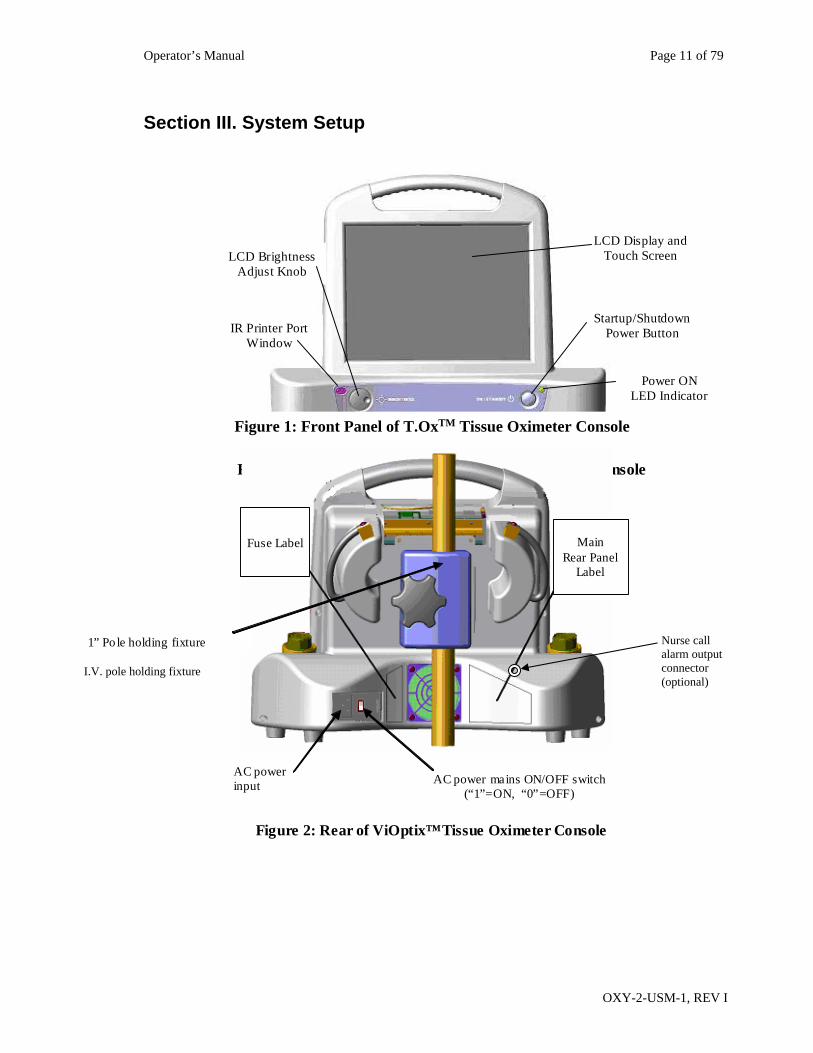
Figure 1: Front Panel of ViOptix™Tissue Oximeter Console
Power ON LED Indicator
LCD Brightness Adjust Knob
IR Printer Port Window
LCD Display and Touch Screen
Startup/Shutdown Power Button
Figure 1: Front Panel of T.OxTM Tissue Oximeter Console
Main Rear Panel
Label
Fuse Label
AC power input AC power mains ON/OFF switch
(“1”=ON, “0”=OFF)
1” Po le holding fixture
Figure 2: Rear of ViOptix™Tissue Oximeter Console
Nurse call alarm output connector (optional)
I.V. pole holding fixture
Operator’s Manual Page 12 of 79
OXY-2-USM-1, REV I
A. System Configuration
1. Connecting the T.Ox™ Tissue Oximeter a. Plug the AC (alternating current) power cord into the back of the T.Ox™ Tissue
Oximeter computer console module (see Figure 2). b. Plug the AC power cord into a power source. c. Place the back panel AC Power Switch to the ON (1) position d. Attach sensor(s) to one or two channels’ connector(s). e. Attach optional 10 foot nurse call alarm output cable from the nurse call output
connector (refer to Figure 2) and an available bedside nurse call system jack. To attach the cable, press the cable’s circular connector onto the rear panel connector and rotate until it clicks and locks. To detach cable, pull back on the cable connector’s metal sleeve.
2. Turning on the T.Ox™ Tissue Oximeter Turn on the T.Ox™ Tissue Oximeter by depressing the soft ON/Standby power button on the right front of the console. (Refer to Figure 1) The main screen is displayed after console initialization and self-tests have been performed. The power ON LED will flash slowly while the system is starting up. Quick flashing of the power ON LED indicates the battery is being used during startup. Connect AC power to the console; otherwise the battery will eventually be depleted.
3. Battery Operation The console is not intended to be operated continuously under battery power. The battery will provide up to 30 minutes of normal operation and is rechargeable but continuous use of the battery under low voltage conditions might damage the battery. If AC is removed then use the battery to save logged data and power down the unit.
B. Using the T.Ox™ Tissue Oximeter Controls
1. AC Power Switch The AC Power switch is on the back of the console. This switch routes AC power to the console’s power supply.
2. ON/Standby Button Depressing the ON/Standby power button on the right front of the console applies power to, or removes power from, the console electronics. (See Figure 1.) To turn the unit off, hold the ON/Standby button in, then release it after 3 seconds. The console will perform a shutdown sequence and then power off. Note: If patient data was recorded but not saved before shutdown, the Oops Save Discard screen (Figure 3) will be displayed. This screen requires the operator to take action (cancel shutdown, save, or discard the data) before the console powers off.
Operator’s Manual Page 13 of 79
OXY-2-USM-1, REV I
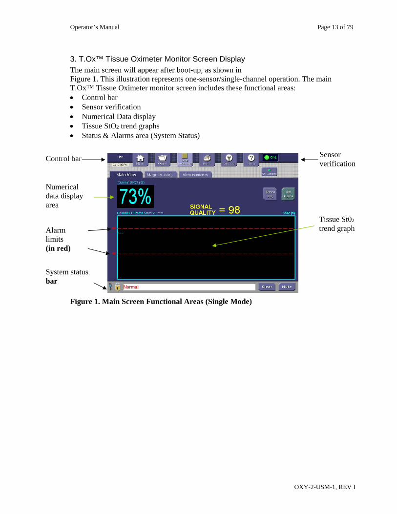
3. T.Ox™ Tissue Oximeter Monitor Screen Display The main screen will appear after boot-up, as shown in Figure 1. This illustration represents one-sensor/single-channel operation. The main T.Ox™ Tissue Oximeter monitor screen includes these functional areas: Control bar Sensor verification Numerical Data display Tissue StO2 trend graphs Status & Alarms area (System Status)
Figure 1. Main Screen Functional Areas (Single Mode)
Sensor verification
Tissue St02 trend graph
Control bar
Alarm limits (in red)
System status bar
Numerical data display area
Operator’s Manual Page 14 of 79
OXY-2-USM-1, REV I
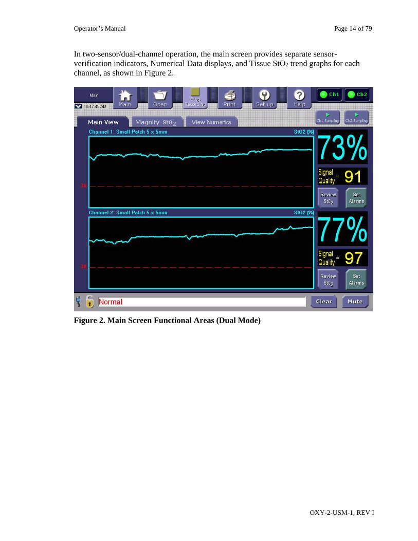
In two-sensor/dual-channel operation, the main screen provides separate sensor-verification indicators, Numerical Data displays, and Tissue StO2 trend graphs for each channel, as shown in Figure 2.
Figure 2. Main Screen Functional Areas (Dual Mode)
Operator’s Manual Page 15 of 79
OXY-2-USM-1, REV I
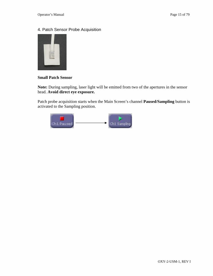
4. Patch Sensor Probe Acquisition
Small Patch Sensor Note: During sampling, laser light will be emitted from two of the apertures in the sensor head. Avoid direct eye exposure. Patch probe acquisition starts when the Main Screen’s channel Paused/Sampling button is activated to the Sampling position.
Operator’s Manual Page 16 of 79
OXY-2-USM-1, REV I
6. Recording Patient Data When the Recording button is lighted (Stop Recording text displayed), the function is active and will log and save data while any sampling is being performed. This is the default operating condition. During channel data acquisition (sampling), the console logs the data in channel-specific temporary files. You can convert these files to permanently-saved data files by tapping the Control Bar’s Stop Recording button and selecting Save in the Oops Save Discard screen. Tapping the Stop Recording button will display the Oops Save Discard screen if any patient data has been acquired. This screen gives the operator the option (Oops) to return to the previous screen, the option to discard the data or the option to save the data. Once the data is saved or discarded the temporary data file is closed. When the operator saves the data in an operator-specified file, that data file will be permanently saved in the console and available for review and off-loading using the Control Bar’s Open and Setup/Send files buttons. If the Stop Recording button is tapped and no patient data has been acquired, the console performs no operation and retains the current screen. You can review the current session’s StO2 data from the Main Screen by tapping the appropriate channel’s Review StO2 soft button. Recording is used primarily for long-term monitoring; short-term monitoring may not require the recording of data. There are 200 Megabytes (MB) of disk storage area for logged data. The equivalent of three months of continuously recorded, two-channel data can be stored and reviewed. Reference Recording a New File (Saving) for a description of file/data storage use and limitations. The Main Screen Review StO2 buttons become available only after data has been acquired. The console displays only the selected StO2 data logged at the time the Review StO2 button is tapped. The console continues to log data while displaying the Review StO2 screen. To review the latest data the operator must return to the Main Screen and tap the Review StO2 button again.
Operator’s Manual Page 17 of 79
OXY-2-USM-1, REV I
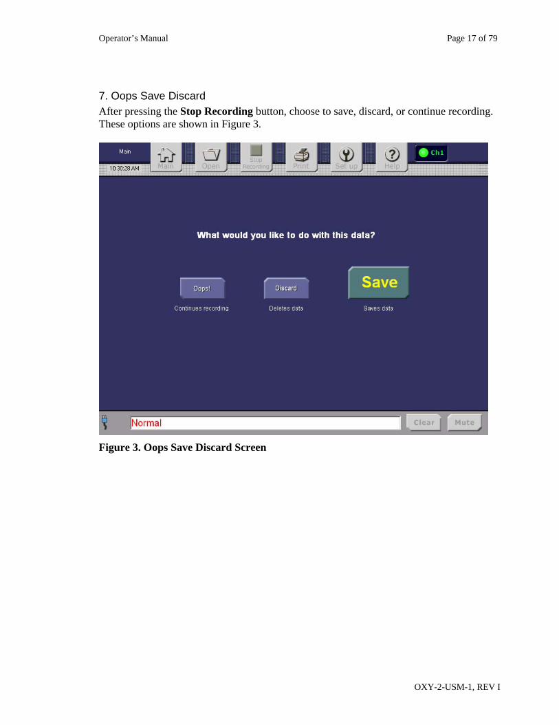
7. Oops Save Discard After pressing the Stop Recording button, choose to save, discard, or continue recording. These options are shown in Figure 3.
Figure 3. Oops Save Discard Screen
Operator’s Manual Page 18 of 79
OXY-2-USM-1, REV I
Section IV. System Operation
A. Site Preparation 1. Make sure that the tissue site to be measured is clean and unobstructed to ensure good
skin contact. Avoid placement of sensors over large vessels or bony prominences, as readings may be affected.
2. Apply light pressure over the muscle tissue, somewhat greater pressure over adipose tissue.
3. Check for good skin contact and no light leakage around the sensor contact point. 4. Pause data collection when moving the sensor from one tissue site to another. When
using a patch sensor, toggle the channel Sampling/Paused button on the display monitor screen to pause data collection.
B. Data Acquisition
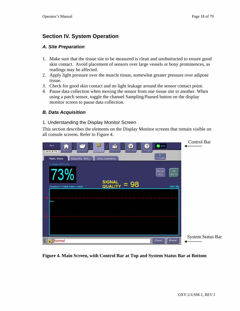
1. Understanding the Display Monitor Screen This section describes the elements on the Display Monitor screens that remain visible on all console screens. Refer to Figure 4.
Figure 4. Main Screen, with Control Bar at Top and System Status Bar at Bottom
Control Bar
System Status Bar
Operator’s Manual Page 19 of 79
OXY-2-USM-1, REV I
The Control Bar along the top of the screen displays six buttons that can be used to move from screen to screen as needed. Refer to Table 1. The Screen Name is shown at the top left of the screen. The current time is displayed below the Screen Name. How the time is displayed can be set up in the Time Setup screen. The display in the upper right corner of the screen indicates the channel(s) that are being used. Figure 4 shows one channel in use. Channel lights will display in green if the corresponding channel is being used to take readings. Small-Patch Sampling When using patch sensors, Sampling/Paused soft buttons with lights are displayed to indicate whether readings are actively being taken (Sampling) or if the system is in Paused mode: When using the patch sensors, press the on-screen Ch1 Paused button in the upper right corner to start data sampling. The Ch1 Paused button will change to Ch1 Sampling.
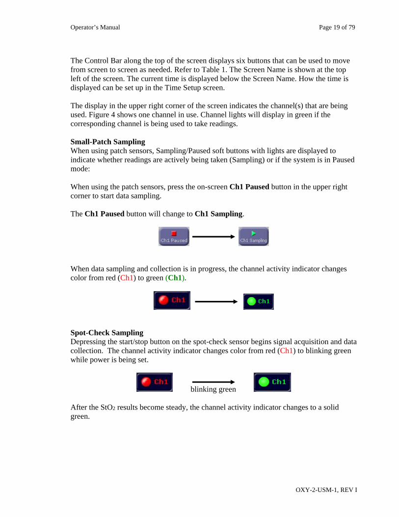
When data sampling and collection is in progress, the channel activity indicator changes color from red (Ch1) to green (Ch1).
Spot-Check Sampling Depressing the start/stop button on the spot-check sensor begins signal acquisition and data collection. The channel activity indicator changes color from red (Ch1) to blinking green while power is being set.
blinking green After the StO2 results become steady, the channel activity indicator changes to a solid green.
Operator’s Manual Page 20 of 79
OXY-2-USM-1, REV I
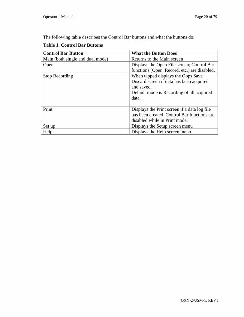
The following table describes the Control Bar buttons and what the buttons do:
Table 1. Control Bar Buttons
Control Bar Button What the Button Does Main (both single and dual mode) Returns to the Main screen Open Displays the Open File screen; Control Bar
functions (Open, Record, etc.) are disabled. Stop Recording
When tapped displays the Oops Save Discard screen if data has been acquired and saved. Default mode is Recording of all acquired data.
Print Displays the Print screen if a data log file has been created. Control Bar functions are disabled while in Print mode.
Set up Displays the Setup screen menu Help Displays the Help screen menu
Operator’s Manual Page 21 of 79
OXY-2-USM-1, REV I
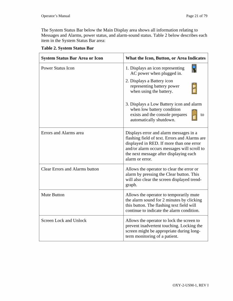
The System Status Bar below the Main Display area shows all information relating to Messages and Alarms, power status, and alarm-sound status. Table 2 below describes each item in the System Status Bar area:
Table 2. System Status Bar
System Status Bar Area or Icon What the Icon, Button, or Area Indicates
Power Status Icon 1. Displays an icon representing AC power when plugged in.
2. Displays a Battery icon representing battery power when using the battery.
3. Displays a Low Battery icon and alarm
when low battery condition exists and the console prepares to automatically shutdown.
Errors and Alarms area Displays error and alarm messages in a flashing field of text. Errors and Alarms are displayed in RED. If more than one error and/or alarm occurs messages will scroll to the next message after displaying each alarm or error.
Clear Errors and Alarms button Allows the operator to clear the error or alarm by pressing the Clear button. This will also clear the screen displayed trend-graph.
Mute Button Allows the operator to temporarily mute the alarm sound for 2 minutes by clicking this button. The flashing text field will continue to indicate the alarm condition.
Screen Lock and Unlock Allows the operator to lock the screen to prevent inadvertent touching. Locking the screen might be appropriate during long-term monitoring of a patient.
Operator’s Manual Page 22 of 79
OXY-2-USM-1, REV I
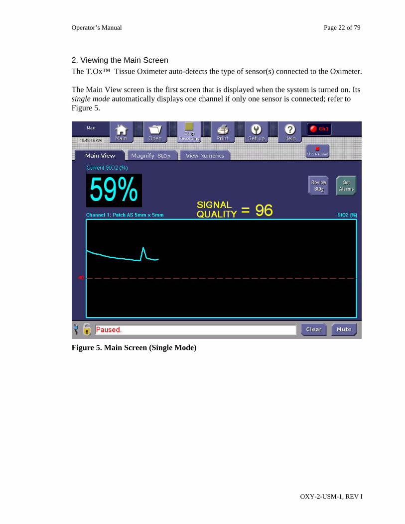
2. Viewing the Main Screen The T.Ox™ Tissue Oximeter auto-detects the type of sensor(s) connected to the Oximeter. The Main View screen is the first screen that is displayed when the system is turned on. Its single mode automatically displays one channel if only one sensor is connected; refer to Figure 5.
Figure 5. Main Screen (Single Mode)
Operator’s Manual Page 23 of 79
OXY-2-USM-1, REV I
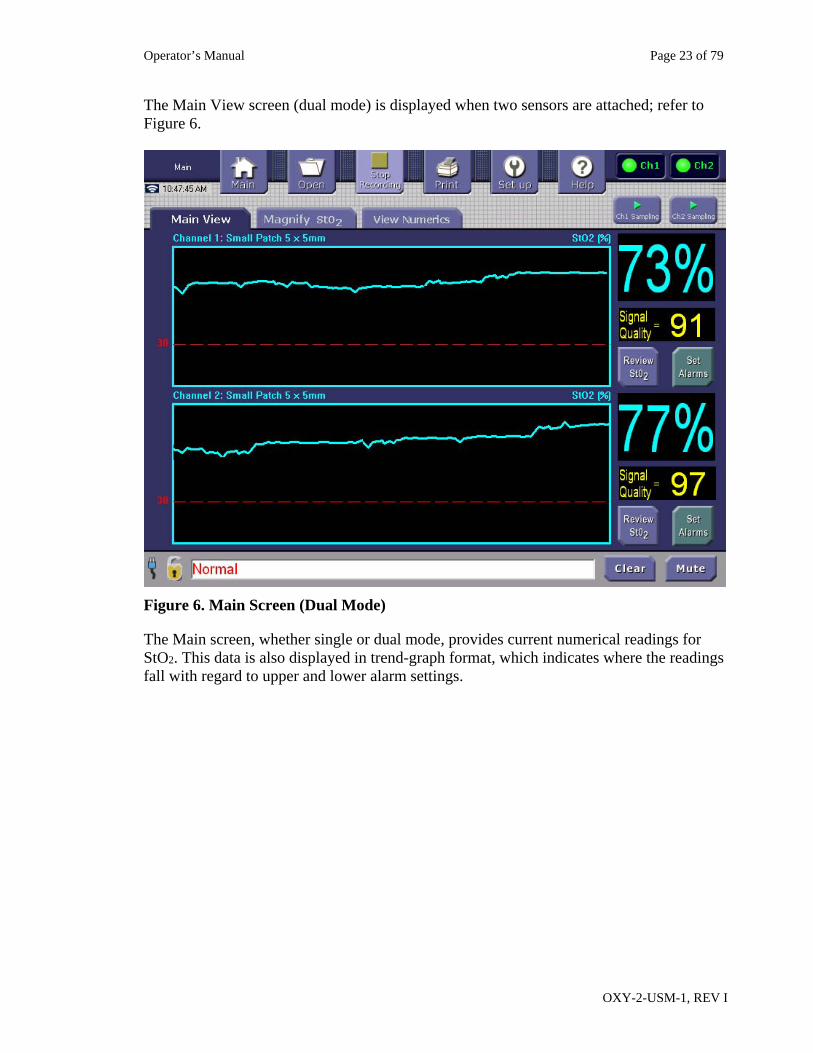
The Main View screen (dual mode) is displayed when two sensors are attached; refer to Figure 6.
Figure 6. Main Screen (Dual Mode)
The Main screen, whether single or dual mode, provides current numerical readings for StO2. This data is also displayed in trend-graph format, which indicates where the readings fall with regard to upper and lower alarm settings.
Operator’s Manual Page 24 of 79
OXY-2-USM-1, REV I
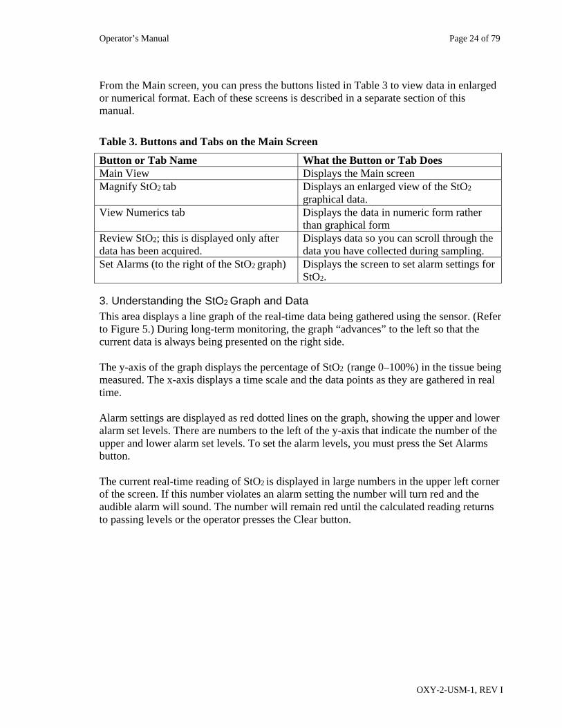
From the Main screen, you can press the buttons listed in Table 3 to view data in enlarged or numerical format. Each of these screens is described in a separate section of this manual.
Table 3. Buttons and Tabs on the Main Screen
Button or Tab Name What the Button or Tab Does Main View Displays the Main screen Magnify StO2 tab Displays an enlarged view of the StO2
graphical data. View Numerics tab Displays the data in numeric form rather
than graphical form Review StO2; this is displayed only after data has been acquired.
Displays data so you can scroll through the data you have collected during sampling.
Set Alarms (to the right of the StO2 graph) Displays the screen to set alarm settings for StO2.
3. Understanding the StO2 Graph and Data This area displays a line graph of the real-time data being gathered using the sensor. (Refer to Figure 5.) During long-term monitoring, the graph “advances” to the left so that the current data is always being presented on the right side. The y-axis of the graph displays the percentage of StO2 (range 0–100%) in the tissue being measured. The x-axis displays a time scale and the data points as they are gathered in real time. Alarm settings are displayed as red dotted lines on the graph, showing the upper and lower alarm set levels. There are numbers to the left of the y-axis that indicate the number of the upper and lower alarm set levels. To set the alarm levels, you must press the Set Alarms button. The current real-time reading of StO2 is displayed in large numbers in the upper left corner of the screen. If this number violates an alarm setting the number will turn red and the audible alarm will sound. The number will remain red until the calculated reading returns to passing levels or the operator presses the Clear button.
Operator’s Manual Page 25 of 79
OXY-2-USM-1, REV I
4. Understanding Signal Quality Use the Oximeter’s Signal Quality indicator to guide you in positioning the sensor for reliable StO2 readings. Signal quality measures the consistency of the readings among the sensor’s four detectors. The higher the consistency, the more reliable the reading. Specifically:
Signal quality of 100% is ideal. However, this maximum value is rarely obtained in practice.
Signal quality of 80%–100% is normally considered “good” or “satisfactory.” This is the Oximeter’s operating range.
Signal quality below 80% is normally considered “low.” Readings in this range may be unreliable. Therefore, when the signal quality falls below this criterion, the Oximeter suppresses StO2 values in its display and logging.
Although StO2 and signal quality are both measured as percentages, keep in mind that they are distinct quantities. The signal quality is a guide to the reliability of the StO2 reading. The Oximeter’s display reinforces this distinction by presenting the two percentages in different sizes and colors.
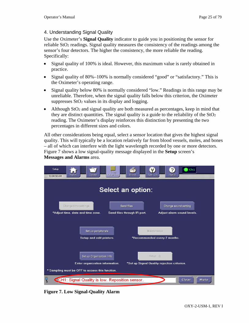
All other considerations being equal, select a sensor location that gives the highest signal quality. This will typically be a location relatively far from blood vessels, moles, and bones – all of which can interfere with the light wavelength recorded by one or more detectors. Figure 7 shows a low signal-quality message displayed in the Setup screen’s Messages and Alarms area.
Figure 7. Low Signal-Quality Alarm
Operator’s Manual Page 26 of 79
OXY-2-USM-1, REV I
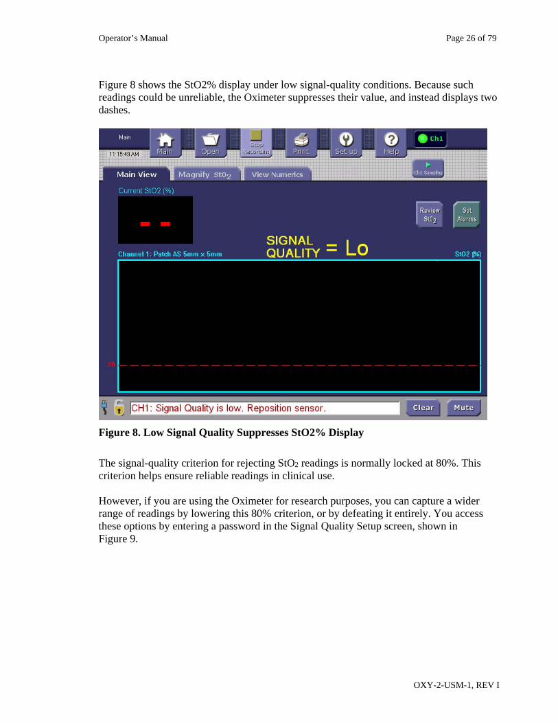
Figure 8 shows the StO2% display under low signal-quality conditions. Because such readings could be unreliable, the Oximeter suppresses their value, and instead displays two dashes.
Figure 8. Low Signal Quality Suppresses StO2% Display
The signal-quality criterion for rejecting StO2 readings is normally locked at 80%. This criterion helps ensure reliable readings in clinical use. However, if you are using the Oximeter for research purposes, you can capture a wider range of readings by lowering this 80% criterion, or by defeating it entirely. You access these options by entering a password in the Signal Quality Setup screen, shown in Figure 9.
Operator’s Manual Page 27 of 79
OXY-2-USM-1, REV I
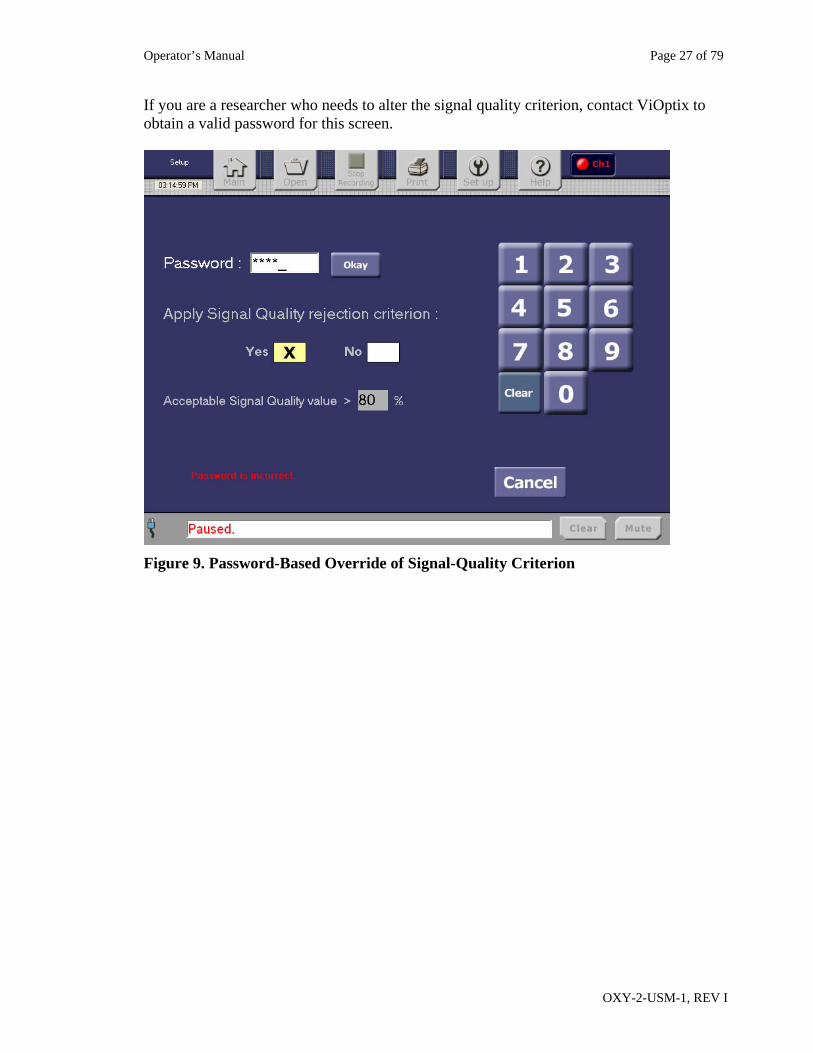
If you are a researcher who needs to alter the signal quality criterion, contact ViOptix to obtain a valid password for this screen.
Figure 9. Password-Based Override of Signal-Quality Criterion
Operator’s Manual Page 28 of 79
OXY-2-USM-1, REV I
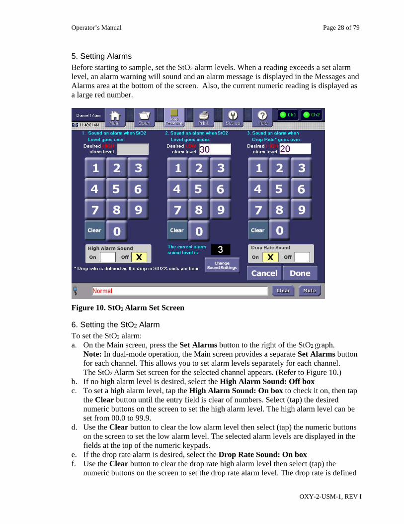
5. Setting Alarms Before starting to sample, set the StO2 alarm levels. When a reading exceeds a set alarm level, an alarm warning will sound and an alarm message is displayed in the Messages and Alarms area at the bottom of the screen. Also, the current numeric reading is displayed as a large red number.
Figure 10. StO2 Alarm Set Screen
6. Setting the StO2 Alarm To set the StO2 alarm: a. On the Main screen, press the Set Alarms button to the right of the StO2 graph.
Note: In dual-mode operation, the Main screen provides a separate Set Alarms button for each channel. This allows you to set alarm levels separately for each channel. The StO2 Alarm Set screen for the selected channel appears. (Refer to Figure 10.)
b. If no high alarm level is desired, select the High Alarm Sound: Off box c. To set a high alarm level, tap the High Alarm Sound: On box to check it on, then tap
the Clear button until the entry field is clear of numbers. Select (tap) the desired numeric buttons on the screen to set the high alarm level. The high alarm level can be set from 00.0 to 99.9.
d. Use the Clear button to clear the low alarm level then select (tap) the numeric buttons on the screen to set the low alarm level. The selected alarm levels are displayed in the fields at the top of the numeric keypads.
e. If the drop rate alarm is desired, select the Drop Rate Sound: On box f. Use the Clear button to clear the drop rate high alarm level then select (tap) the
numeric buttons on the screen to set the drop rate alarm level. The drop rate is defined
Operator’s Manual Page 29 of 79
OXY-2-USM-1, REV I
as the drop in tissue oxygen saturation in St02 % units per hour. If the drop rate alarm level is exceeded for more than 30 minutes, the alarm will sound.
g. To change the sound level of the alarm, press Change Sound Settings to go to that screen.
h. When finished, press Done to save the selections and return to the previous screen. (Press Cancel to discard the selections and return to the previous screen).
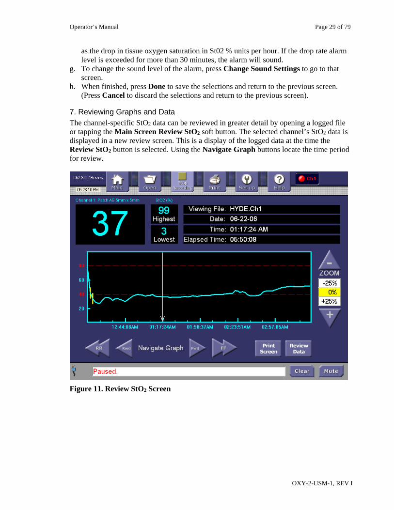
7. Reviewing Graphs and Data The channel-specific StO2 data can be reviewed in greater detail by opening a logged file or tapping the Main Screen Review StO2 soft button. The selected channel’s StO2 data is displayed in a new review screen. This is a display of the logged data at the time the Review StO2 button is selected. Using the Navigate Graph buttons locate the time period for review.
Figure 11. Review StO2 Screen
Operator’s Manual Page 30 of 79
OXY-2-USM-1, REV I
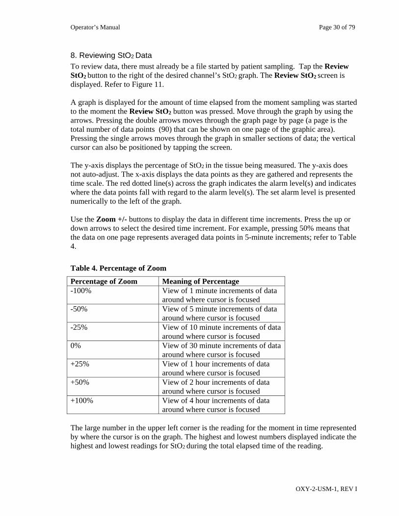
8. Reviewing StO2 Data To review data, there must already be a file started by patient sampling. Tap the Review StO2 button to the right of the desired channel’s StO2 graph. The Review StO2 screen is displayed. Refer to Figure 11. A graph is displayed for the amount of time elapsed from the moment sampling was started to the moment the Review StO2 button was pressed. Move through the graph by using the arrows. Pressing the double arrows moves through the graph page by page (a page is the total number of data points (90) that can be shown on one page of the graphic area). Pressing the single arrows moves through the graph in smaller sections of data; the vertical cursor can also be positioned by tapping the screen. The y-axis displays the percentage of StO2 in the tissue being measured. The y-axis does not auto-adjust. The x-axis displays the data points as they are gathered and represents the time scale. The red dotted line(s) across the graph indicates the alarm level(s) and indicates where the data points fall with regard to the alarm level(s). The set alarm level is presented numerically to the left of the graph. Use the Zoom +/- buttons to display the data in different time increments. Press the up or down arrows to select the desired time increment. For example, pressing 50% means that the data on one page represents averaged data points in 5-minute increments; refer to Table 4.
Table 4. Percentage of Zoom
Percentage of Zoom Meaning of Percentage -100% View of 1 minute increments of data
around where cursor is focused -50% View of 5 minute increments of data
around where cursor is focused -25% View of 10 minute increments of data
around where cursor is focused 0% View of 30 minute increments of data
around where cursor is focused +25% View of 1 hour increments of data
around where cursor is focused +50% View of 2 hour increments of data
around where cursor is focused +100% View of 4 hour increments of data
around where cursor is focused The large number in the upper left corner is the reading for the moment in time represented by where the cursor is on the graph. The highest and lowest numbers displayed indicate the highest and lowest readings for StO2 during the total elapsed time of the reading.
Operator’s Manual Page 31 of 79
OXY-2-USM-1, REV I
Also displayed on the Review screen are the following: Viewing File: field shows the name of the file Date: field shows the date of the data where the cursor is positioned Time: field shows the time of the data where the cursor is positioned. Time is displayed
in the current 24-hour or AM/PM format selected from the Setup/Change time settings menus.
Elapsed Time: field shows in hours/minutes/seconds format how much time has elapsed from the start of the recording of the data to the present cursor position..
To print a Summary Report of the data, press the top Control Bar’s Print button. Refer to the Printing Data section. The Summary Report will print the entire collection of StO2 data values in numerical table format. To print a Snapshot Report (Print Screen) of the data, press the Print Screen button. The Snapshot Report will only print the segment of data presented on the current Review StO2 screen. The Review Data button will display the current graphed data in numerical table format. Refer to the “Reviewing StO2 Data” section on page 30. If two sensors are being used, the system is in dual mode. Each channel has a Review StO2
button to display the StO2 results for that channel.
Operator’s Manual Page 32 of 79
OXY-2-USM-1, REV I
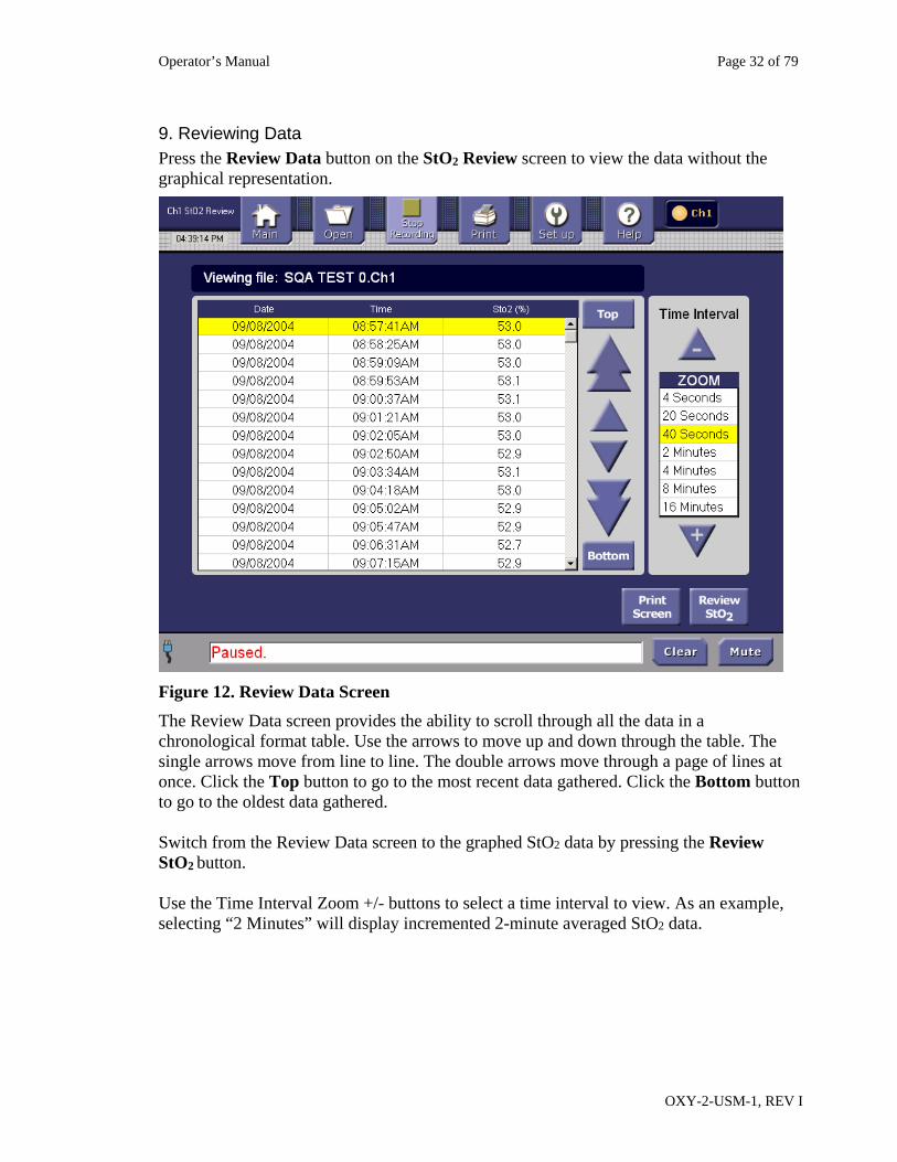
9. Reviewing Data Press the Review Data button on the StO2 Review screen to view the data without the graphical representation.
Figure 12. Review Data Screen
The Review Data screen provides the ability to scroll through all the data in a chronological format table. Use the arrows to move up and down through the table. The single arrows move from line to line. The double arrows move through a page of lines at once. Click the Top button to go to the most recent data gathered. Click the Bottom button to go to the oldest data gathered. Switch from the Review Data screen to the graphed StO2 data by pressing the Review StO2 button. Use the Time Interval Zoom +/- buttons to select a time interval to view. As an example, selecting “2 Minutes” will display incremented 2-minute averaged StO2 data.
Operator’s Manual Page 33 of 79
OXY-2-USM-1, REV I
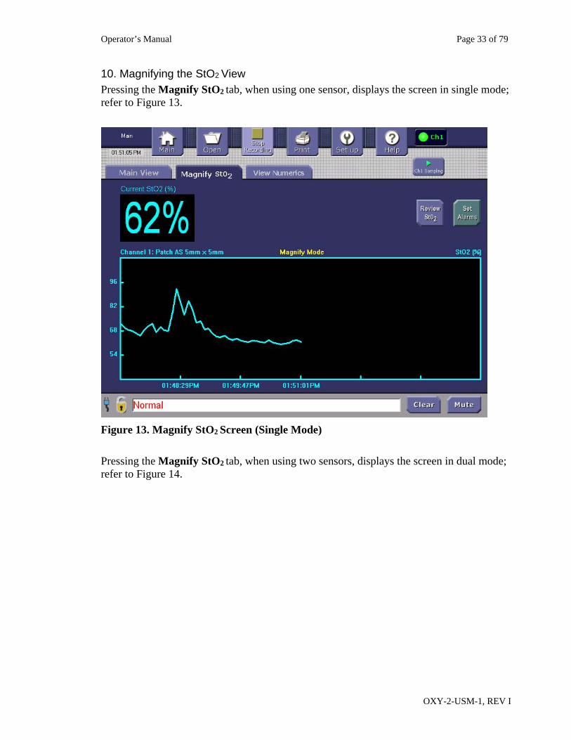
10. Magnifying the StO2 View Pressing the Magnify StO2 tab, when using one sensor, displays the screen in single mode; refer to Figure 13.
Figure 13. Magnify StO2 Screen (Single Mode)
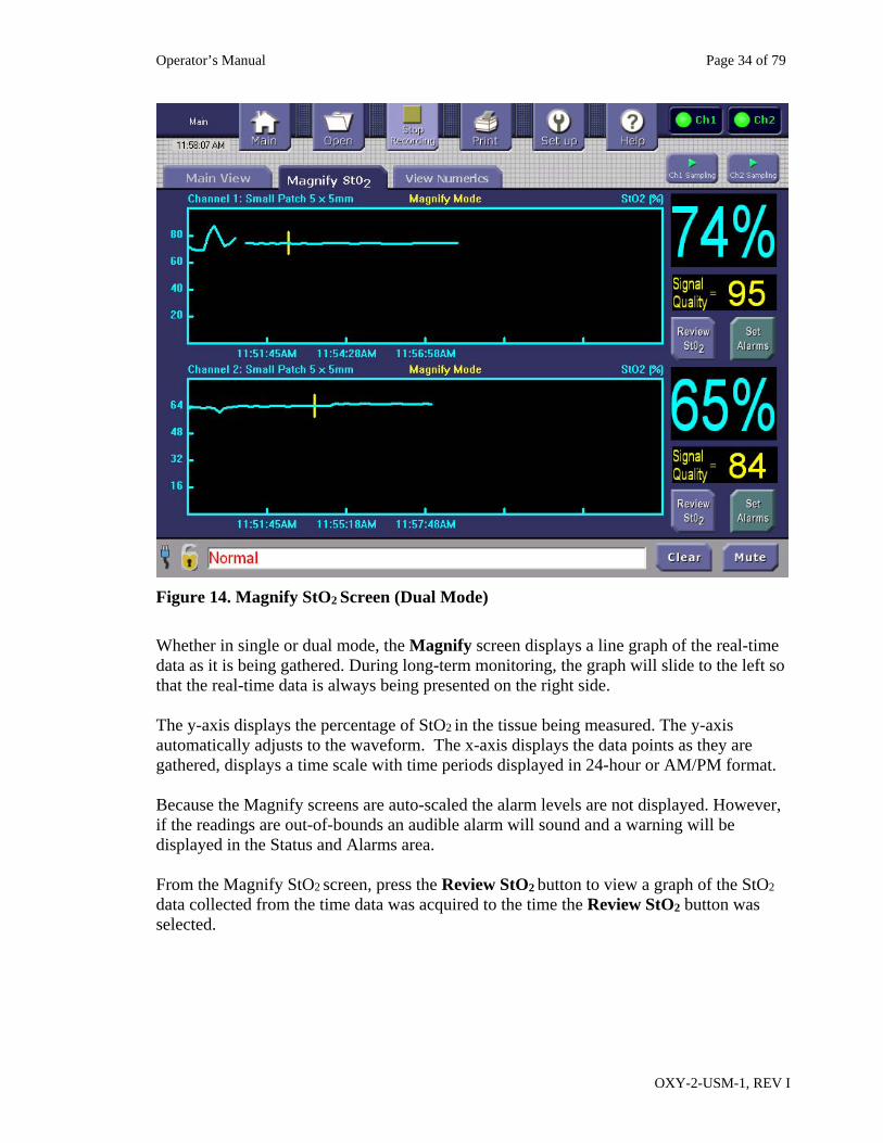
Pressing the Magnify StO2 tab, when using two sensors, displays the screen in dual mode; refer to Figure 14.
Operator’s Manual Page 34 of 79
OXY-2-USM-1, REV I
Figure 14. Magnify StO2 Screen (Dual Mode)
Whether in single or dual mode, the Magnify screen displays a line graph of the real-time data as it is being gathered. During long-term monitoring, the graph will slide to the left so that the real-time data is always being presented on the right side. The y-axis displays the percentage of StO2 in the tissue being measured. The y-axis automatically adjusts to the waveform. The x-axis displays the data points as they are gathered, displays a time scale with time periods displayed in 24-hour or AM/PM format. Because the Magnify screens are auto-scaled the alarm levels are not displayed. However, if the readings are out-of-bounds an audible alarm will sound and a warning will be displayed in the Status and Alarms area. From the Magnify StO2 screen, press the Review StO2 button to view a graph of the StO2 data collected from the time data was acquired to the time the Review StO2 button was selected.
Operator’s Manual Page 35 of 79
OXY-2-USM-1, REV I
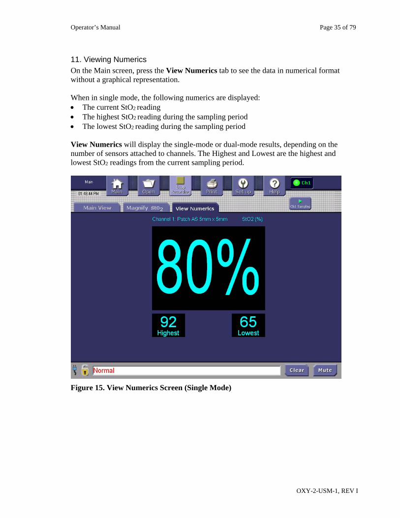
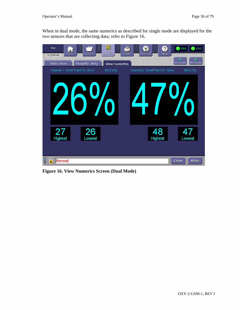
11. Viewing Numerics On the Main screen, press the View Numerics tab to see the data in numerical format without a graphical representation. When in single mode, the following numerics are displayed: The current StO2 reading The highest StO2 reading during the sampling period The lowest StO2 reading during the sampling period View Numerics will display the single-mode or dual-mode results, depending on the number of sensors attached to channels. The Highest and Lowest are the highest and lowest StO2 readings from the current sampling period.
Figure 15. View Numerics Screen (Single Mode)
Operator’s Manual Page 36 of 79
OXY-2-USM-1, REV I
When in dual mode, the same numerics as described for single mode are displayed for the two sensors that are collecting data; refer to Figure 16.
Figure 16. View Numerics Screen (Dual Mode)
Operator’s Manual Page 37 of 79
OXY-2-USM-1, REV I
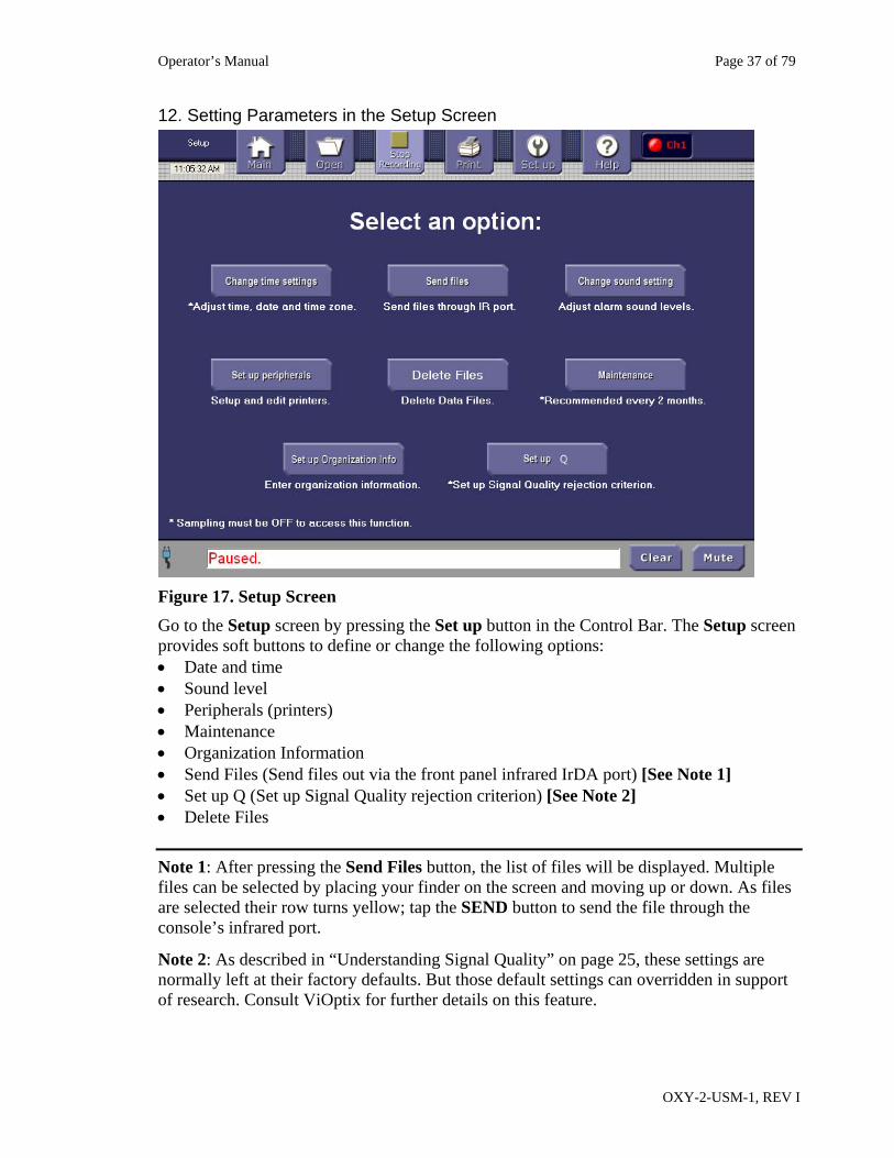
12. Setting Parameters in the Setup Screen
Figure 17. Setup Screen
Go to the Setup screen by pressing the Set up button in the Control Bar. The Setup screen provides soft buttons to define or change the following options: Date and time Sound level Peripherals (printers) Maintenance Organization Information Send Files (Send files out via the front panel infrared IrDA port) [See Note 1] Set up Q (Set up Signal Quality rejection criterion) [See Note 2] Delete Files
Note 1: After pressing the Send Files button, the list of files will be displayed. Multiple files can be selected by placing your finder on the screen and moving up or down. As files are selected their row turns yellow; tap the SEND button to send the file through the console’s infrared port.
Note 2: As described in “Understanding Signal Quality” on page 25, these settings are normally left at their factory defaults. But those default settings can overridden in support of research. Consult ViOptix for further details on this feature.
Operator’s Manual Page 38 of 79
OXY-2-USM-1, REV I
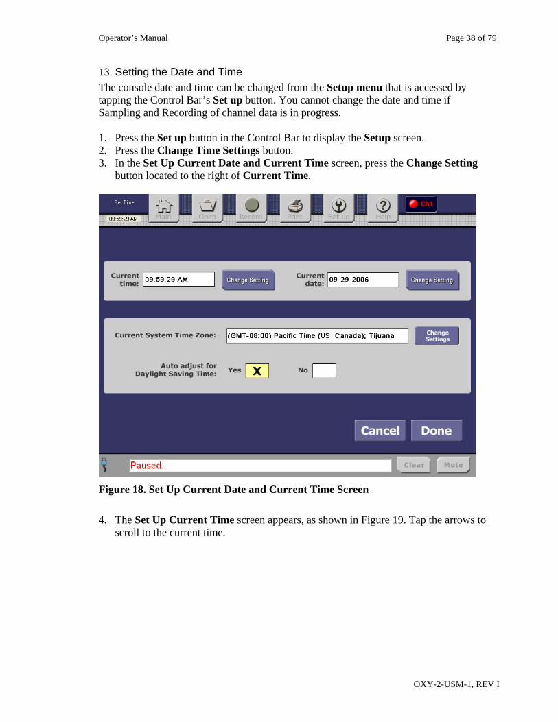
13. Setting the Date and Time
The console date and time can be changed from the Setup menu that is accessed by tapping the Control Bar’s Set up button. You cannot change the date and time if Sampling and Recording of channel data is in progress. 1. Press the Set up button in the Control Bar to display the Setup screen. 2. Press the Change Time Settings button. 3. In the Set Up Current Date and Current Time screen, press the Change Setting
button located to the right of Current Time.
Figure 18. Set Up Current Date and Current Time Screen
4. The Set Up Current Time screen appears, as shown in Figure 19. Tap the arrows to
scroll to the current time.
Operator’s Manual Page 39 of 79
OXY-2-USM-1, REV I
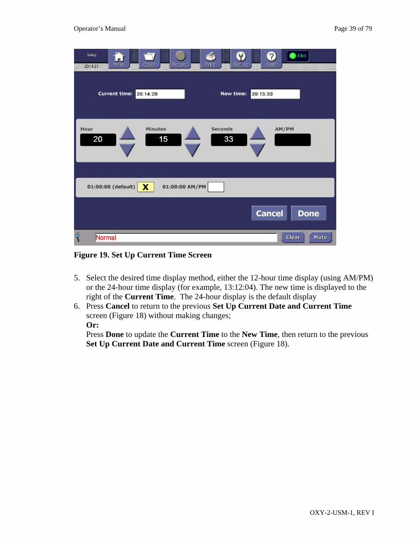
Figure 19. Set Up Current Time Screen
5. Select the desired time display method, either the 12-hour time display (using AM/PM)
or the 24-hour time display (for example, 13:12:04). The new time is displayed to the right of the Current Time. The 24-hour display is the default display
6. Press Cancel to return to the previous Set Up Current Date and Current Time screen (Figure 18) without making changes; Or: Press Done to update the Current Time to the New Time, then return to the previous Set Up Current Date and Current Time screen (Figure 18).
Operator’s Manual Page 40 of 79
OXY-2-USM-1, REV I
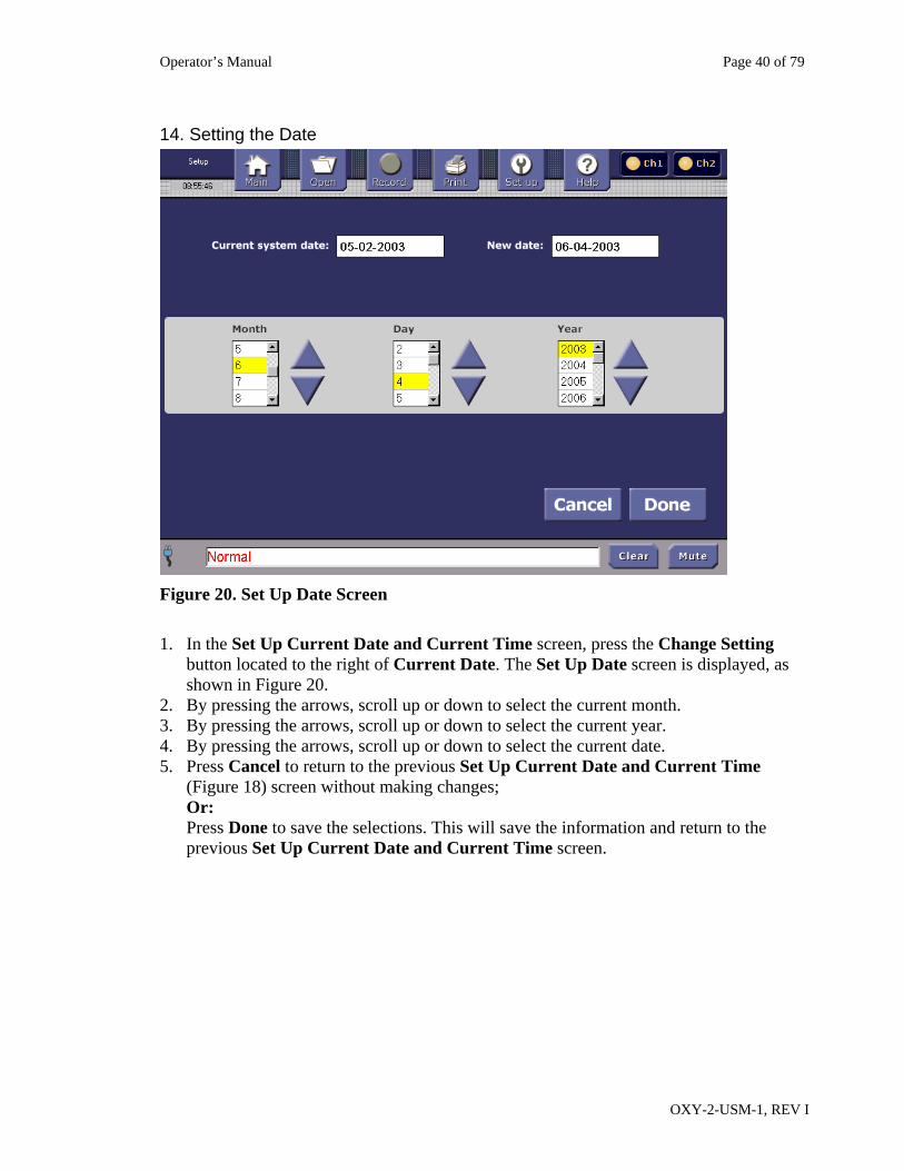
14. Setting the Date
Figure 20. Set Up Date Screen
1. In the Set Up Current Date and Current Time screen, press the Change Setting
button located to the right of Current Date. The Set Up Date screen is displayed, as shown in Figure 20.
2. By pressing the arrows, scroll up or down to select the current month. 3. By pressing the arrows, scroll up or down to select the current year. 4. By pressing the arrows, scroll up or down to select the current date. 5. Press Cancel to return to the previous Set Up Current Date and Current Time
(Figure 18) screen without making changes; Or: Press Done to save the selections. This will save the information and return to the previous Set Up Current Date and Current Time screen.
Operator’s Manual Page 41 of 79
OXY-2-USM-1, REV I
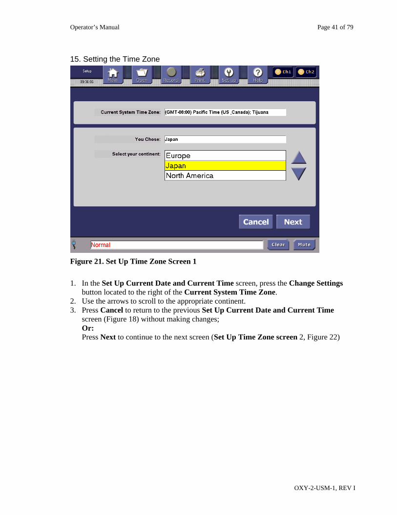
15. Setting the Time Zone
Figure 21. Set Up Time Zone Screen 1
1. In the Set Up Current Date and Current Time screen, press the Change Settings
button located to the right of the Current System Time Zone. 2. Use the arrows to scroll to the appropriate continent. 3. Press Cancel to return to the previous Set Up Current Date and Current Time
screen (Figure 18) without making changes; Or: Press Next to continue to the next screen (Set Up Time Zone screen 2, Figure 22)
Operator’s Manual Page 42 of 79
OXY-2-USM-1, REV I
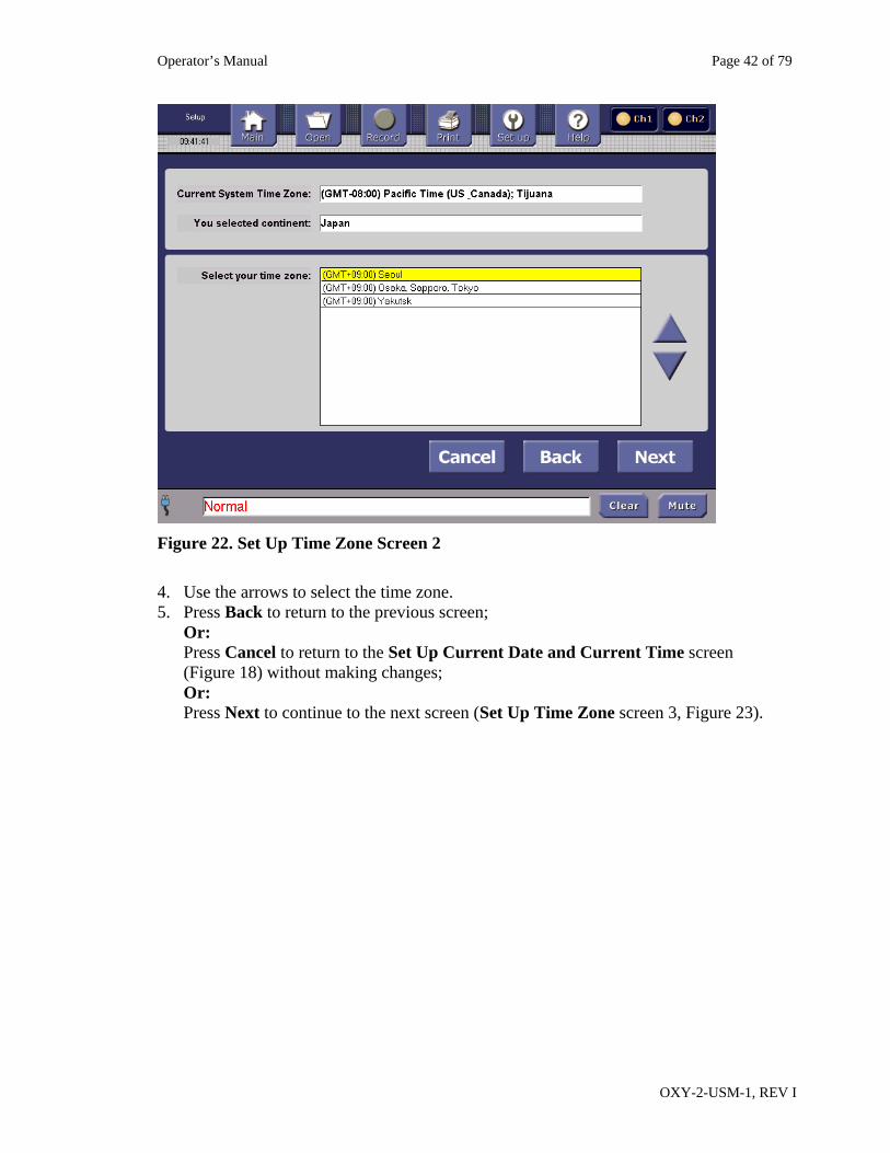
Figure 22. Set Up Time Zone Screen 2
4. Use the arrows to select the time zone. 5. Press Back to return to the previous screen;
Or: Press Cancel to return to the Set Up Current Date and Current Time screen (Figure 18) without making changes; Or: Press Next to continue to the next screen (Set Up Time Zone screen 3, Figure 23).
Operator’s Manual Page 43 of 79
OXY-2-USM-1, REV I
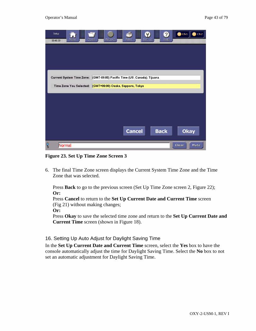
Figure 23. Set Up Time Zone Screen 3
6. The final Time Zone screen displays the Current System Time Zone and the Time
Zone that was selected. Press Back to go to the previous screen (Set Up Time Zone screen 2, Figure 22); Or: Press Cancel to return to the Set Up Current Date and Current Time screen (Fig 21) without making changes; Or: Press Okay to save the selected time zone and return to the Set Up Current Date and Current Time screen (shown in Figure 18).
16. Setting Up Auto Adjust for Daylight Saving Time In the Set Up Current Date and Current Time screen, select the Yes box to have the console automatically adjust the time for Daylight Saving Time. Select the No box to not set an automatic adjustment for Daylight Saving Time.
Operator’s Manual Page 44 of 79
OXY-2-USM-1, REV I
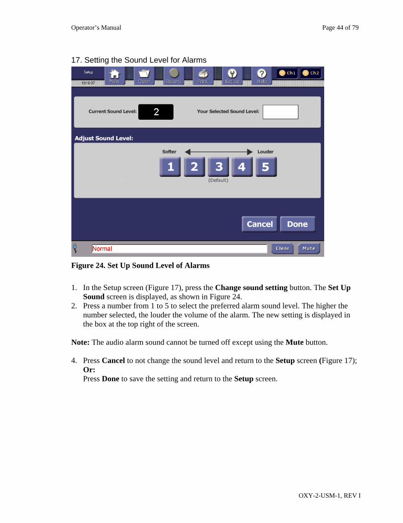
17. Setting the Sound Level for Alarms
Figure 24. Set Up Sound Level of Alarms
1. In the Setup screen (Figure 17), press the Change sound setting button. The Set Up
Sound screen is displayed, as shown in Figure 24. 2. Press a number from 1 to 5 to select the preferred alarm sound level. The higher the
number selected, the louder the volume of the alarm. The new setting is displayed in the box at the top right of the screen.
Note: The audio alarm sound cannot be turned off except using the Mute button. 4. Press Cancel to not change the sound level and return to the Setup screen (Figure 17);
Or: Press Done to save the setting and return to the Setup screen.
Operator’s Manual Page 45 of 79
OXY-2-USM-1, REV I
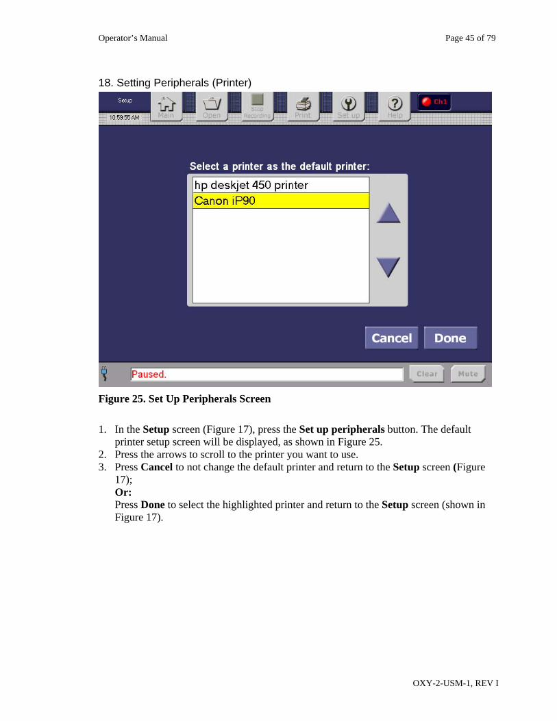
18. Setting Peripherals (Printer)
Figure 25. Set Up Peripherals Screen
1. In the Setup screen (Figure 17), press the Set up peripherals button. The default
printer setup screen will be displayed, as shown in Figure 25. 2. Press the arrows to scroll to the printer you want to use. 3. Press Cancel to not change the default printer and return to the Setup screen (Figure
17); Or: Press Done to select the highlighted printer and return to the Setup screen (shown in Figure 17).
Operator’s Manual Page 46 of 79
OXY-2-USM-1, REV I
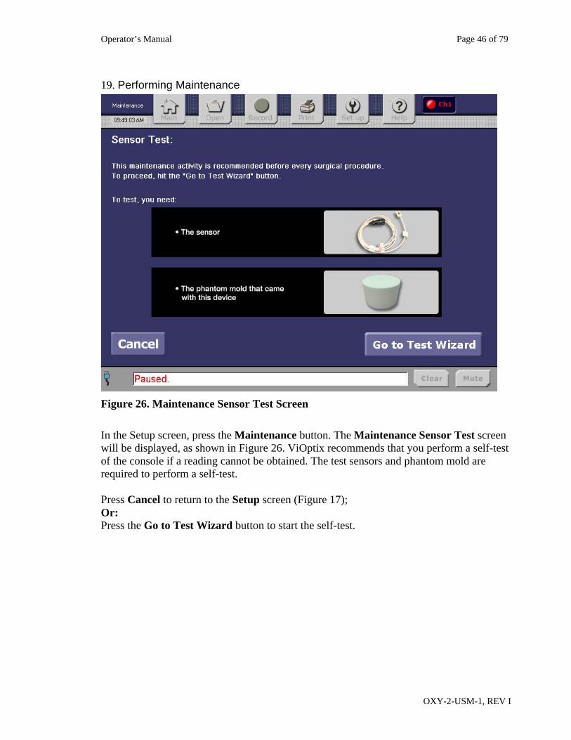
19. Performing Maintenance
Figure 26. Maintenance Sensor Test Screen
In the Setup screen, press the Maintenance button. The Maintenance Sensor Test screen will be displayed, as shown in Figure 26. ViOptix recommends that you perform a self-test of the console if a reading cannot be obtained. The test sensors and phantom mold are required to perform a self-test. Press Cancel to return to the Setup screen (Figure 17); Or: Press the Go to Test Wizard button to start the self-test.
Operator’s Manual Page 47 of 79
OXY-2-USM-1, REV I
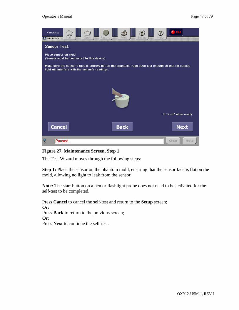
Figure 27. Maintenance Screen, Step 1
The Test Wizard moves through the following steps: Step 1: Place the sensor on the phantom mold, ensuring that the sensor face is flat on the mold, allowing no light to leak from the sensor. Note: The start button on a pen or flashlight probe does not need to be activated for the self-test to be completed. Press Cancel to cancel the self-test and return to the Setup screen; Or: Press Back to return to the previous screen; Or: Press Next to continue the self-test.
Operator’s Manual Page 48 of 79
OXY-2-USM-1, REV I
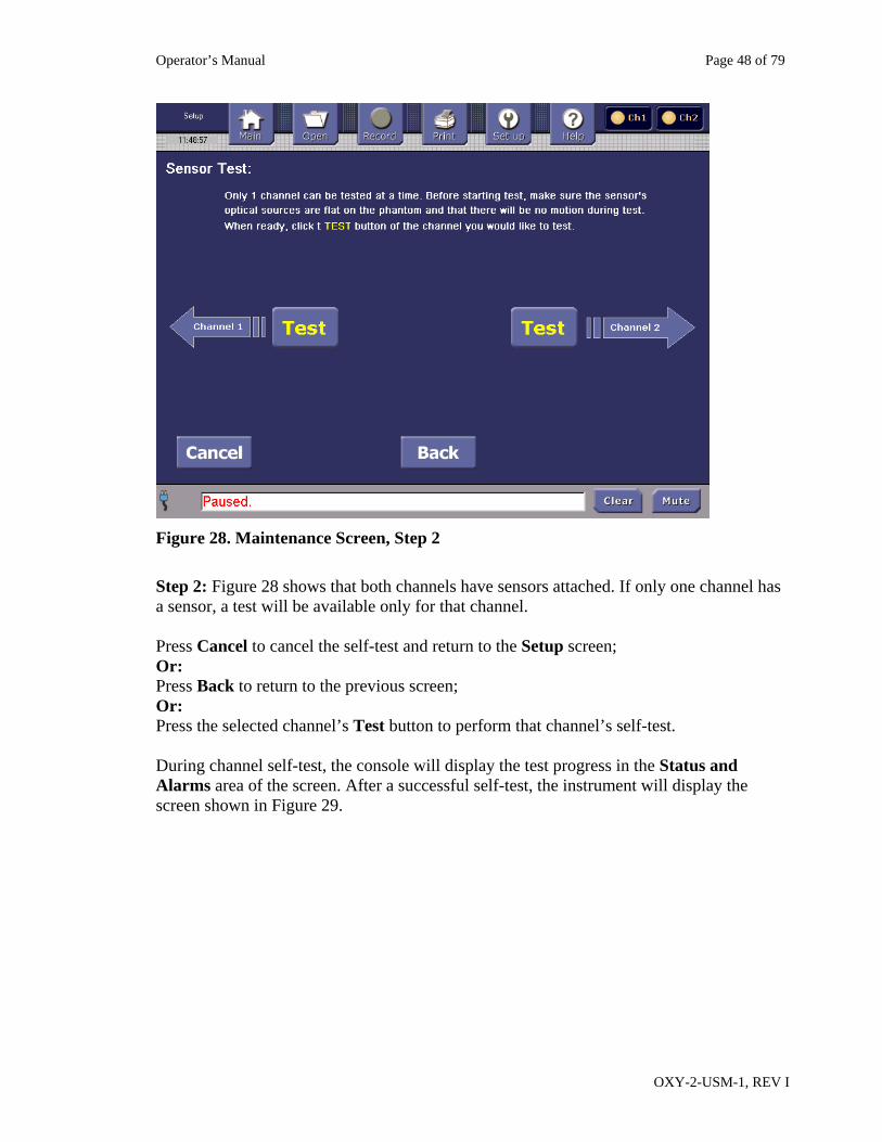
Figure 28. Maintenance Screen, Step 2
Step 2: Figure 28 shows that both channels have sensors attached. If only one channel has a sensor, a test will be available only for that channel. Press Cancel to cancel the self-test and return to the Setup screen; Or: Press Back to return to the previous screen; Or: Press the selected channel’s Test button to perform that channel’s self-test. During channel self-test, the console will display the test progress in the Status and Alarms area of the screen. After a successful self-test, the instrument will display the screen shown in Figure 29.
Operator’s Manual Page 49 of 79
OXY-2-USM-1, REV I
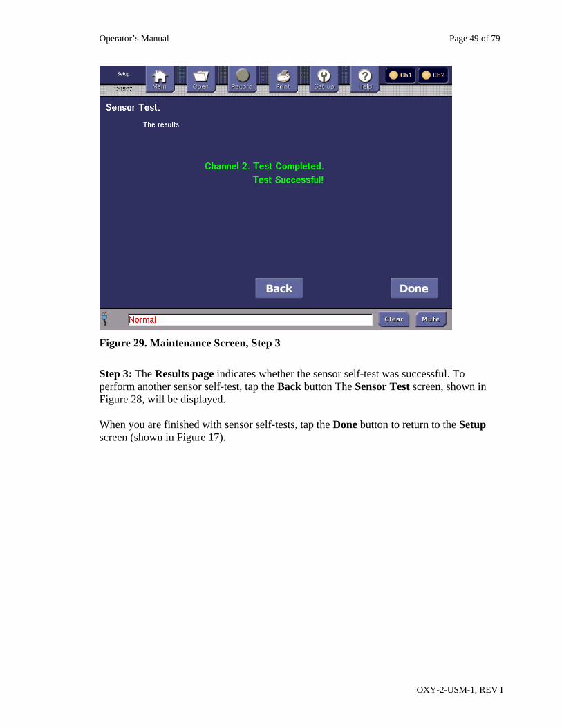
Figure 29. Maintenance Screen, Step 3
Step 3: The Results page indicates whether the sensor self-test was successful. To perform another sensor self-test, tap the Back button The Sensor Test screen, shown in Figure 28, will be displayed. When you are finished with sensor self-tests, tap the Done button to return to the Setup screen (shown in Figure 17).
Operator’s Manual Page 50 of 79
OXY-2-USM-1, REV I
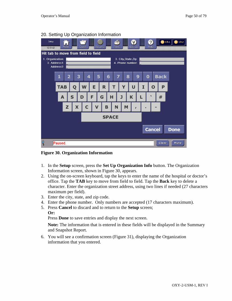
20. Setting Up Organization Information
Figure 30. Organization Information
1. In the Setup screen, press the Set Up Organization Info button. The Organization
Information screen, shown in Figure 30, appears. 2. Using the on-screen keyboard, tap the keys to enter the name of the hospital or doctor’s
office. Tap the TAB key to move from field to field. Tap the Back key to delete a character. Enter the organization street address, using two lines if needed (27 characters maximum per field).
3. Enter the city, state, and zip code. 4. Enter the phone number. Only numbers are accepted (17 characters maximum). 5. Press Cancel to discard and to return to the Setup screen;
Or: Press Done to save entries and display the next screen.
Note: The information that is entered in these fields will be displayed in the Summary and Snapshot Report.
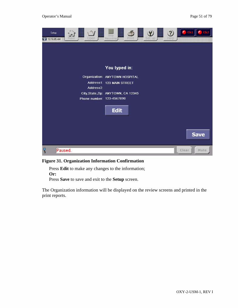
6. You will see a confirmation screen (Figure 31), displaying the Organization information that you entered.
Operator’s Manual Page 51 of 79
OXY-2-USM-1, REV I
Figure 31. Organization Information Confirmation
Press Edit to make any changes to the information; Or: Press Save to save and exit to the Setup screen.
The Organization information will be displayed on the review screens and printed in the print reports.
Operator’s Manual Page 52 of 79
OXY-2-USM-1, REV I
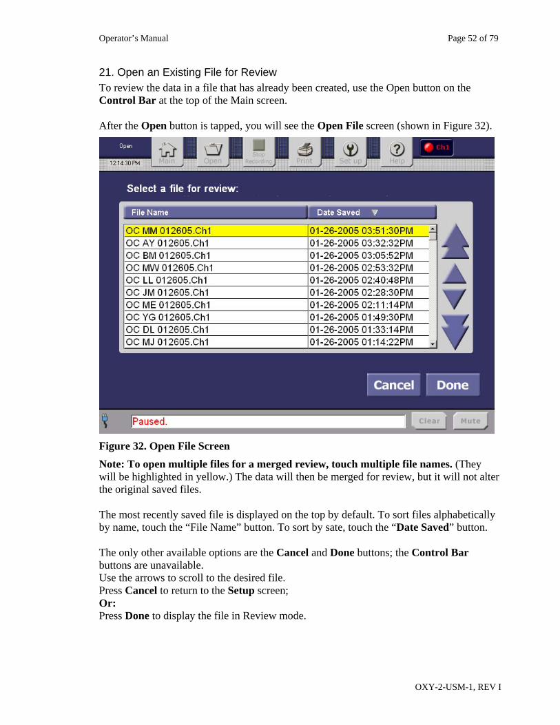
21. Open an Existing File for Review To review the data in a file that has already been created, use the Open button on the Control Bar at the top of the Main screen. After the Open button is tapped, you will see the Open File screen (shown in Figure 32).
Figure 32. Open File Screen
Note: To open multiple files for a merged review, touch multiple file names. (They will be highlighted in yellow.) The data will then be merged for review, but it will not alter the original saved files. The most recently saved file is displayed on the top by default. To sort files alphabetically by name, touch the “File Name” button. To sort by sate, touch the “Date Saved” button. The only other available options are the Cancel and Done buttons; the Control Bar buttons are unavailable. Use the arrows to scroll to the desired file. Press Cancel to return to the Setup screen; Or: Press Done to display the file in Review mode.
Operator’s Manual Page 53 of 79
OXY-2-USM-1, REV I
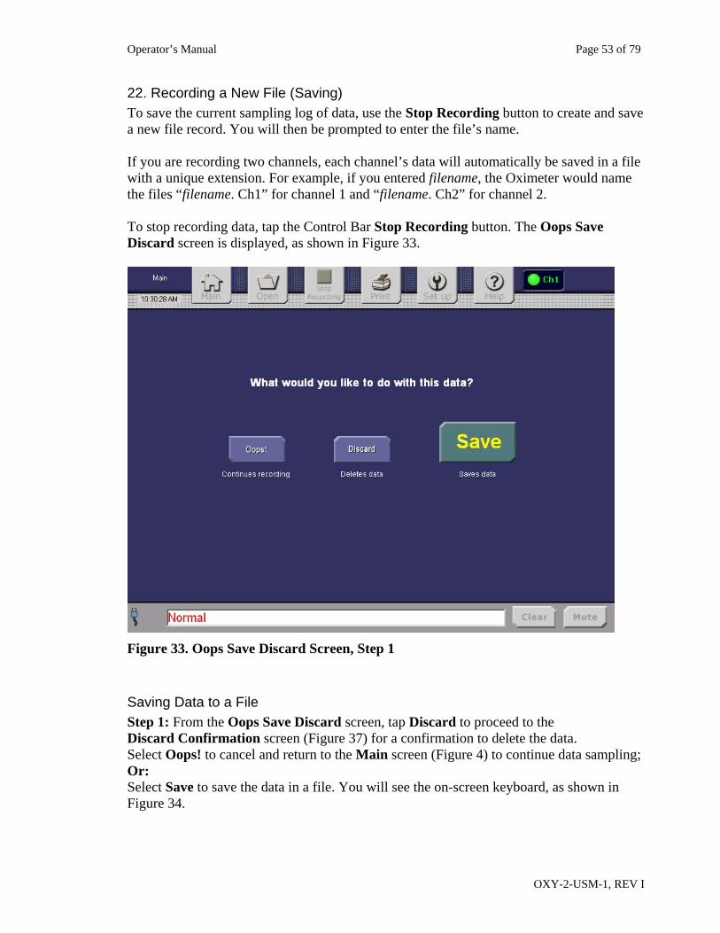
22. Recording a New File (Saving) To save the current sampling log of data, use the Stop Recording button to create and save a new file record. You will then be prompted to enter the file’s name. If you are recording two channels, each channel’s data will automatically be saved in a file with a unique extension. For example, if you entered filename, the Oximeter would name the files “filename. Ch1” for channel 1 and “filename. Ch2” for channel 2. To stop recording data, tap the Control Bar Stop Recording button. The Oops Save Discard screen is displayed, as shown in Figure 33.
Figure 33. Oops Save Discard Screen, Step 1
Saving Data to a File Step 1: From the Oops Save Discard screen, tap Discard to proceed to the Discard Confirmation screen (Figure 37) for a confirmation to delete the data. Select Oops! to cancel and return to the Main screen (Figure 4) to continue data sampling; Or: Select Save to save the data in a file. You will see the on-screen keyboard, as shown in Figure 34.
Operator’s Manual Page 54 of 79
OXY-2-USM-1, REV I
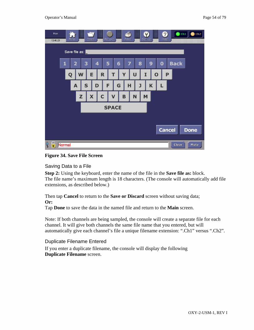
Figure 34. Save File Screen
Saving Data to a File Step 2: Using the keyboard, enter the name of the file in the Save file as: block. The file name’s maximum length is 18 characters. (The console will automatically add file extensions, as described below.) Then tap Cancel to return to the Save or Discard screen without saving data; Or: Tap Done to save the data in the named file and return to the Main screen. Note: If both channels are being sampled, the console will create a separate file for each channel. It will give both channels the same file name that you entered, but will automatically give each channel’s file a unique filename extension: “.Ch1” versus “.Ch2”.
Duplicate Filename Entered If you enter a duplicate filename, the console will display the following Duplicate Filename screen.
Operator’s Manual Page 55 of 79
OXY-2-USM-1, REV I
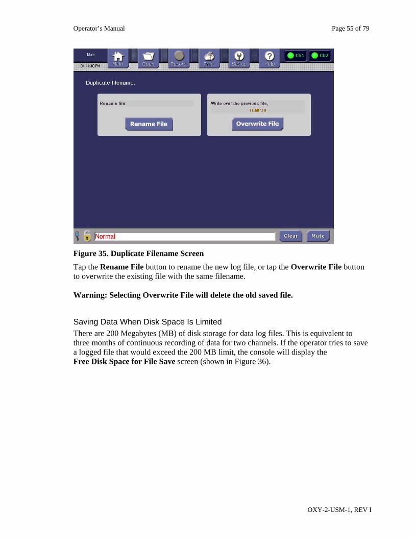
Figure 35. Duplicate Filename Screen
Tap the Rename File button to rename the new log file, or tap the Overwrite File button to overwrite the existing file with the same filename. Warning: Selecting Overwrite File will delete the old saved file.
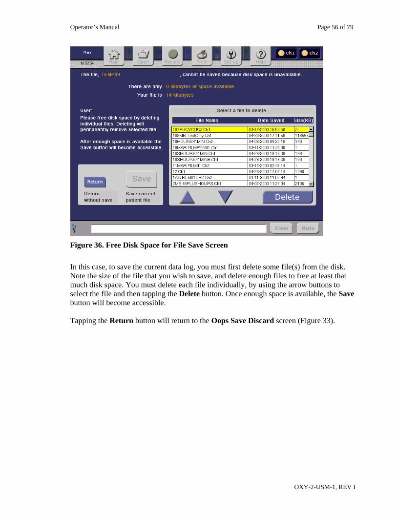
Saving Data When Disk Space Is Limited There are 200 Megabytes (MB) of disk storage for data log files. This is equivalent to three months of continuous recording of data for two channels. If the operator tries to save a logged file that would exceed the 200 MB limit, the console will display the Free Disk Space for File Save screen (shown in Figure 36).
Operator’s Manual Page 56 of 79
OXY-2-USM-1, REV I
Figure 36. Free Disk Space for File Save Screen
In this case, to save the current data log, you must first delete some file(s) from the disk. Note the size of the file that you wish to save, and delete enough files to free at least that much disk space. You must delete each file individually, by using the arrow buttons to select the file and then tapping the Delete button. Once enough space is available, the Save button will become accessible. Tapping the Return button will return to the Oops Save Discard screen (Figure 33).
Operator’s Manual Page 57 of 79
OXY-2-USM-1, REV I
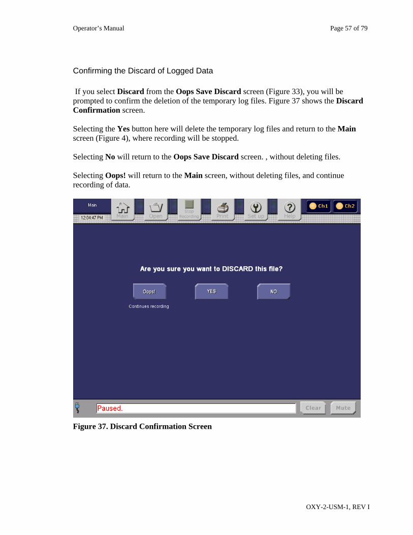
Confirming the Discard of Logged Data If you select Discard from the Oops Save Discard screen (Figure 33), you will be prompted to confirm the deletion of the temporary log files. Figure 37 shows the Discard Confirmation screen. Selecting the Yes button here will delete the temporary log files and return to the Main screen (Figure 4), where recording will be stopped. Selecting No will return to the Oops Save Discard screen. , without deleting files. Selecting Oops! will return to the Main screen, without deleting files, and continue recording of data.
Figure 37. Discard Confirmation Screen
Operator’s Manual Page 58 of 79
OXY-2-USM-1, REV I
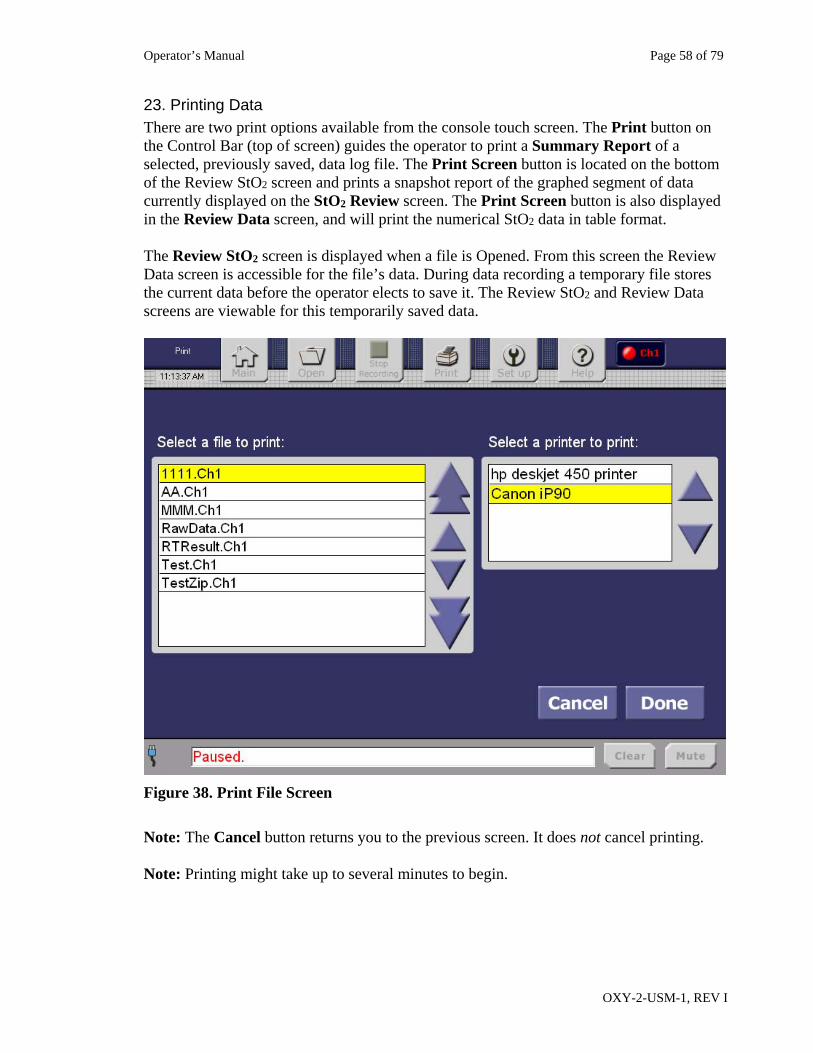
23. Printing Data There are two print options available from the console touch screen. The Print button on the Control Bar (top of screen) guides the operator to print a Summary Report of a selected, previously saved, data log file. The Print Screen button is located on the bottom of the Review StO2 screen and prints a snapshot report of the graphed segment of data currently displayed on the StO2 Review screen. The Print Screen button is also displayed in the Review Data screen, and will print the numerical StO2 data in table format. The Review StO2 screen is displayed when a file is Opened. From this screen the Review Data screen is accessible for the file’s data. During data recording a temporary file stores the current data before the operator elects to save it. The Review StO2 and Review Data screens are viewable for this temporarily saved data.
Figure 38. Print File Screen
Note: The Cancel button returns you to the previous screen. It does not cancel printing. Note: Printing might take up to several minutes to begin.
Operator’s Manual Page 59 of 79
OXY-2-USM-1, REV I
Print a Summary Report From a Saved File To print a Summary Report from a saved file, perform the following steps: 1. From the Control Bar at the top of the screen tap the Print button. A list of files, sorted
in alphanumeric order, is displayed. Up to 10 file names are displayed at one time. Refer to Figure 38.
2. The select bar highlights the current file. To print a different file, use the arrows to scroll to that file.
3. Using the arrows select the printer. 4. Tap Cancel to cancel the print operation. 5. Tap Done to print the file. Note: Ensure that the path to the Infrared (IR) printer is clear before printing.
Print a Snapshot Report (Print Screen) from a Saved File To print a Snapshot Report from a saved file, perform the following steps: 1. Determine which data to print from the file: StO2 graphed data, or StO2 numerical table
data. 2. From the Control Bar tap the Open button and select the file. After you select Done the
StO2 Review screen will be displayed. To print a snapshot of the current displayed StO2 data tap the Print Screen button at the bottom of the screen.
3. To print a snapshot of the StO2 numerical table data tap the Review Data button from the StO2 review screens and, from the Review Data screen tap the Print Screen button. Note: Ensure the path to the Infrared (IR) printer is clear before printing.
Print a Snapshot Report (Print Screen) from a Non-Saved, Current Data File To print a Snapshot Report from the currently recording log, perform the following steps: 1. Determine which data to print from the file: StO2 graphed data, or StO2 numerical table
data. 2. From the Main screen, ensure that sampling and recording are enabled. Then select
Review StO2. 3. At the bottom of the Review screen, tap the Print Screen button. The selected screen
report will be printed.
Operator’s Manual Page 60 of 79
OXY-2-USM-1, REV I
General Print Information Print Button
A Summary Report contains the time-tagged logged StO2 results in table format. To print a Summary Report, press the Control Bar’s Print button. The Print menu will appear and will display two lists: a list of files and a list of printers. The file list contains the logged, recorded channel data. Channel-specific data is identified by the “.Ch1” and “.Ch2” extensions. Up and Down arrows are available to search for and select the desired logged data file. The printer list contains the available printers supported by the console and the default printer will be highlighted (see below for default printer selection). To print a file in Summary Report format, perform the following steps: a. Press Print. b. On the Print screen, the file select bar highlights the first file in the list. To print a
different file, use the arrows to find and select the desired file. c. Select the desired printer. d. Tap Done. (Or tap Cancel to cancel print preparation.) Note: Tapping Cancel after tapping Done will not cancel the print job. Print Screen Button
To print a snapshot report of the Review screen data, tap the Print Screen button located at the bottom of the StO2 Review screen. The button will briefly turn gray while the file is being printed. This gray color informs you that the device is trying to print the file. The console will send the report to the selected default printer through the Infrared (IR) port. See Setup for a description of default printer setup. Notes: a. You can display the StO2 Review screen from the Main screen by recording and
sampling a channel (or channels), and selecting the channel’s Review StO2 button. You can also display the Review screen by opening a file containing previously logged data.
b. The Help menu’s Record Start/Stop button provides information about recording and logging data.
c. Ensure that the path to the Infrared (IR) printer is clear before printing. d. “Tap” refers to a press and release of a touch screen button
Setting the Default Printer
a. From the Main screen, tap the Set up button. b. From the Setup screen, select Set up peripherals. This will display a list of the
available printers.
Operator’s Manual Page 61 of 79
OXY-2-USM-1, REV I
c. Use the Up/Down arrows to select a printer, then tap Done to save the selection and return to the Setup screen. Or, cancel default printer selection, tap Cancel; the Setup screen will be redisplayed.
24. Reports
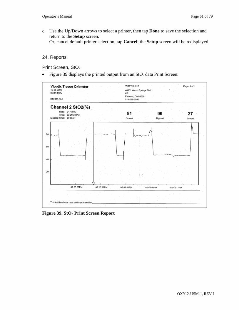
Print Screen, StO2
Figure 39 displays the printed output from an StO2 data Print Screen.
Figure 39. StO2 Print Screen Report
Operator’s Manual Page 62 of 79
OXY-2-USM-1, REV I
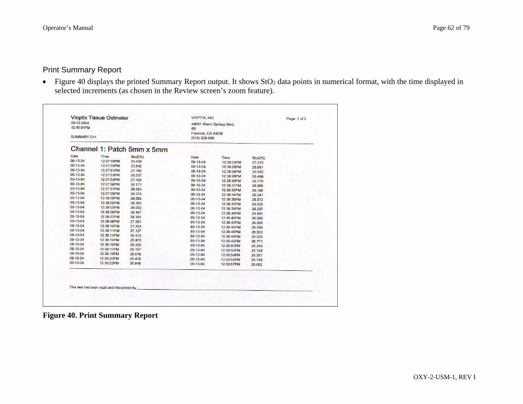
Print Summary Report
Figure 40 displays the printed Summary Report output. It shows StO2 data points in numerical format, with the time displayed in selected increments (as chosen in the Review screen’s zoom feature).
Figure 40. Print Summary Report
Operator’s Manual Page 63 of 79
OXY-2-USM-1, REV I
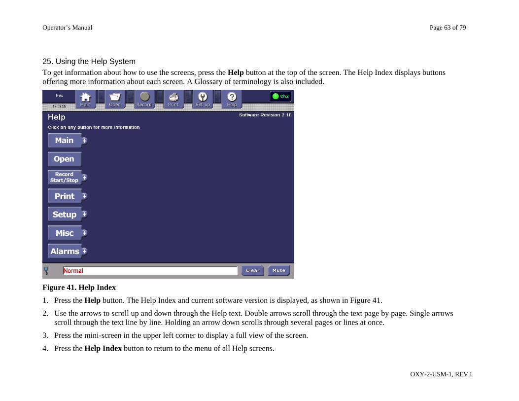
25. Using the Help System To get information about how to use the screens, press the Help button at the top of the screen. The Help Index displays buttons offering more information about each screen. A Glossary of terminology is also included.
Figure 41. Help Index
1. Press the Help button. The Help Index and current software version is displayed, as shown in Figure 41.
2. Use the arrows to scroll up and down through the Help text. Double arrows scroll through the text page by page. Single arrows scroll through the text line by line. Holding an arrow down scrolls through several pages or lines at once.
3. Press the mini-screen in the upper left corner to display a full view of the screen.
4. Press the Help Index button to return to the menu of all Help screens.
Operator’s Manual Page 64 of 79
OXY-2-USM-1, REV I
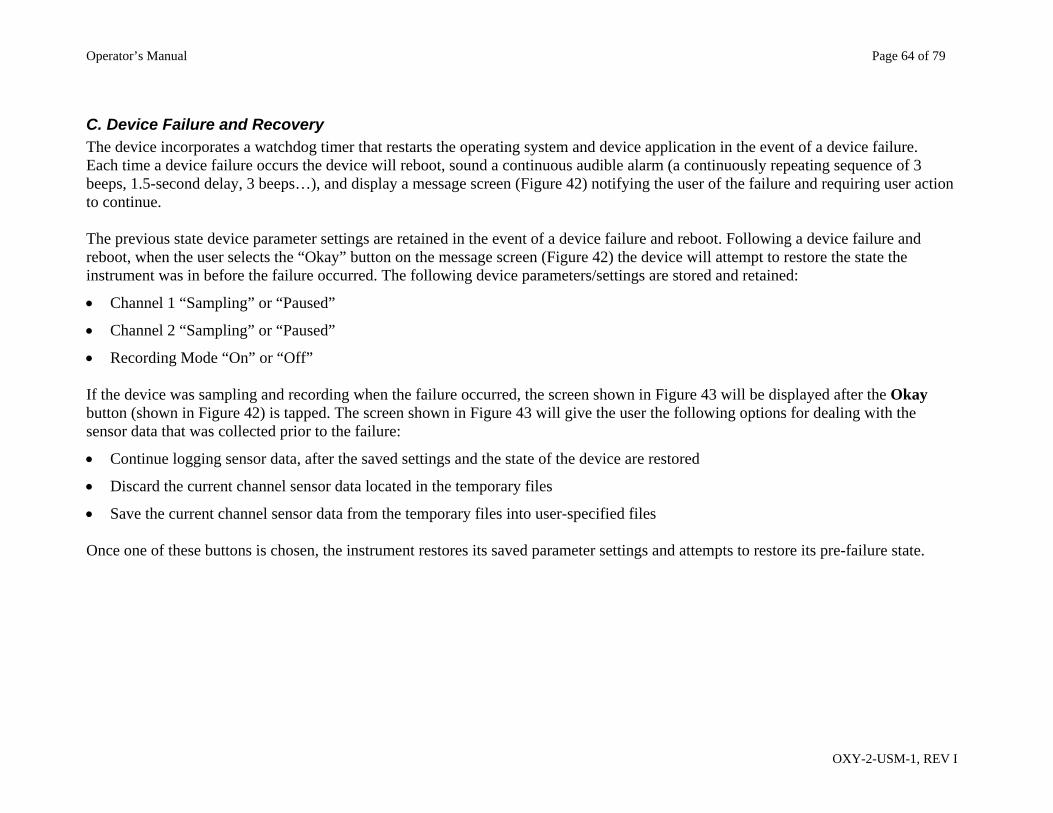
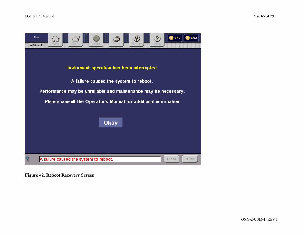
C. Device Failure and Recovery The device incorporates a watchdog timer that restarts the operating system and device application in the event of a device failure. Each time a device failure occurs the device will reboot, sound a continuous audible alarm (a continuously repeating sequence of 3 beeps, 1.5-second delay, 3 beeps…), and display a message screen (Figure 42) notifying the user of the failure and requiring user action to continue. The previous state device parameter settings are retained in the event of a device failure and reboot. Following a device failure and reboot, when the user selects the “Okay” button on the message screen (Figure 42) the device will attempt to restore the state the instrument was in before the failure occurred. The following device parameters/settings are stored and retained:
Channel 1 “Sampling” or “Paused”
Channel 2 “Sampling” or “Paused”
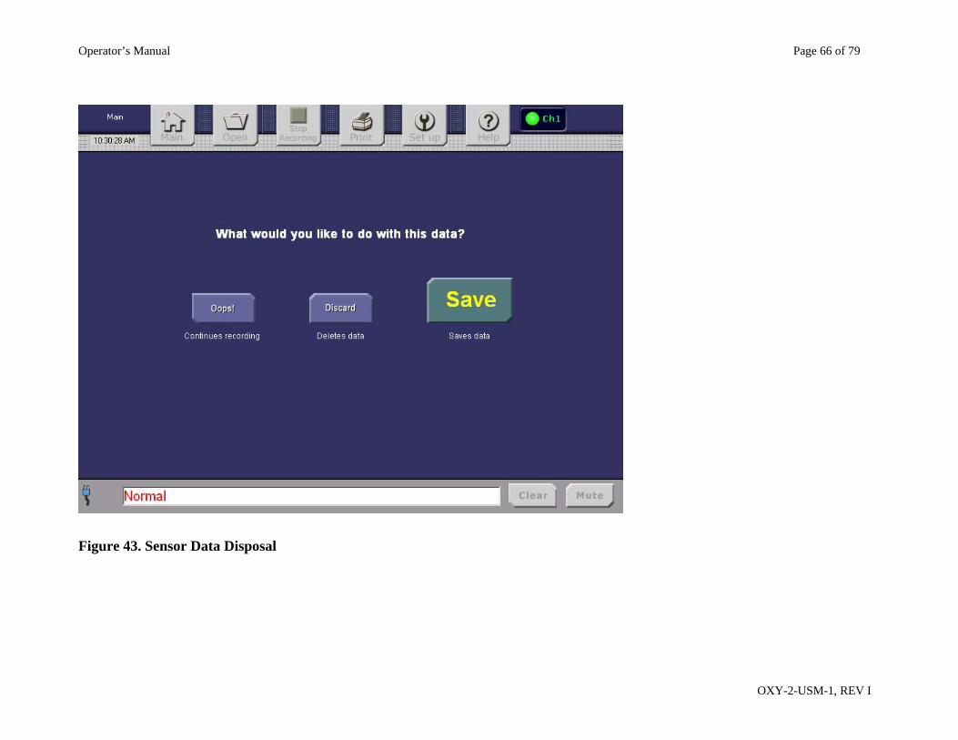
Recording Mode “On” or “Off” If the device was sampling and recording when the failure occurred, the screen shown in Figure 43 will be displayed after the Okay button (shown in Figure 42) is tapped. The screen shown in Figure 43 will give the user the following options for dealing with the sensor data that was collected prior to the failure:
Continue logging sensor data, after the saved settings and the state of the device are restored
Discard the current channel sensor data located in the temporary files
Save the current channel sensor data from the temporary files into user-specified files Once one of these buttons is chosen, the instrument restores its saved parameter settings and attempts to restore its pre-failure state.
Operator’s Manual Page 65 of 79
OXY-2-USM-1, REV I
Figure 42. Reboot Recovery Screen
Operator’s Manual Page 66 of 79
OXY-2-USM-1, REV I
Figure 43. Sensor Data Disposal
Operator’s Manual Page 67 of 79
OXY-2-USM-1, REV I
Section V. Maintenance
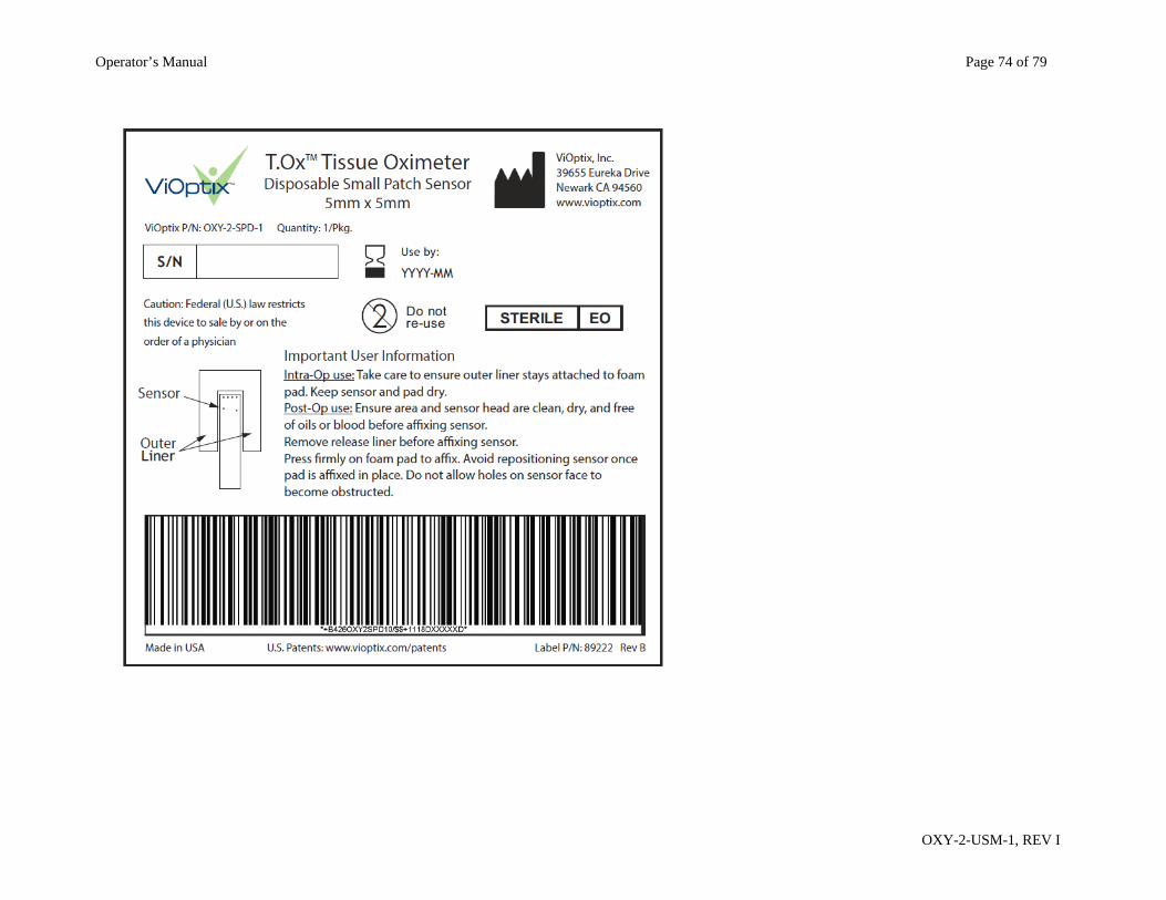
Cleaning and Disinfecting: Disposable Small-Patch Sensors The T.Ox™ Disposable Small Patch Sensors are provided sterile in peel-open packages and are intended for single-patient one-time use. DO NOT REUSE. DO NOT RE-STERILIZE. Dispose of used sensors in accordance with your institution’s biohazard disposal policies. Console Warning: Always disconnect the T.Ox™ Tissue Oximeter unit from any power sources prior to cleaning. To clean the LCD screen, dilute a household water-based glass cleaner with 50% water. Spray a small amount on a soft clean cloth
and gently wipe the screen. The T.Ox™ Tissue Oximeter console exterior can be wiped down with a soft cloth dampened with water. Make sure excess water
has been squeezed out. The connector ends should periodically be cleaned with alcohol and a soft swab.
Warning: Do not soak fiber optic sensors in any solution. Do not use harsh or caustic chemicals. Do not spray cleaner directly onto the console. Keep all liquids, including cleaning fluids, out of any electrical openings.
Operator’s Manual Page 68 of 79
OXY-2-USM-1, REV I
Section VI. Specifications
Console: Tissue Oxygen Saturation Range 0 – 100%
Measurements and Wavelengths
Red 690 nanometers
Infrared 830 nanometers
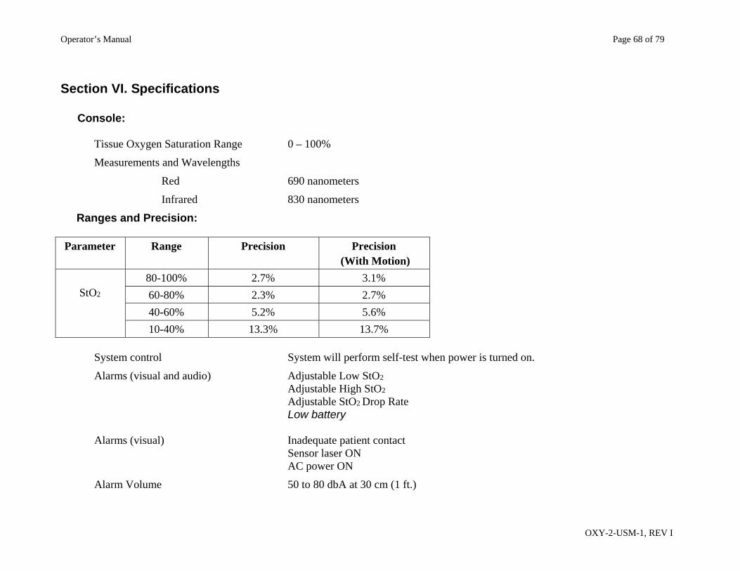
Ranges and Precision: Parameter Range Precision Precision
(With Motion)
StO2
80-100% 2.7% 3.1%
60-80% 2.3% 2.7%
40-60% 5.2% 5.6%
10-40% 13.3% 13.7%
System control System will perform self-test when power is turned on.
Alarms (visual and audio) Adjustable Low StO2 Adjustable High StO2 Adjustable StO2 Drop Rate
Low battery Alarms (visual) Inadequate patient contact Sensor laser ON AC power ON
Alarm Volume 50 to 80 dbA at 30 cm (1 ft.)
Operator’s Manual Page 69 of 79
OXY-2-USM-1, REV I
Battery 3-cell Lithium Ion Battery, 30 minutes minimum
Operating mode Single-channel (default) or dual-channel (applies to consoles with dual channel option when 2 sensors are attached)
Operating Power 100-120 / 200-240 V~, 50-60 Hz
Rated power consumption 50 VA
Protection Type BF, ordinary, continuous operation. The equipment is not suitable for use in the presence of a flammable anesthetic mixture with air, oxygen, or nitrous oxide.
Transport and Storage Temperature: -10C to 40C
Humidity: 20% to 80% (non-condensing)
Atmospheric Pressure 700hPa to 1060hPa
Dimensions 27.5 cm x 38.1 cm x 17.8 cm (11 in x 15 in x 7 in)
Weight 4.3 kg (9.5 lbs)
Sensors: Available in flexible styles
5 mm x 5 mm Flexible sensors are used for continuous monitoring. Laser System: Two pairs of solid state diode lasers, 690 nm and 830 nm per pair, 3 mW max. output
from sensor head. Laser pulse duration 140 milliseconds per laser with pulse repetition frequency of 1.538 seconds during sampling.
Nurse Call Output Option: Optional 4-pin rear panel connector providing both Normally Open (N.O. in non-alarm state) and Normally Closed (N.C. in non-alarm state) relay contact outputs, for use with ViOptix Nurse Call N.O. or N.C. 10 foot output cables. Compatible with standard ¼” nurse call system jacks. UL 1069 compliant design.
Wi-Fi Capability Option: Optional internal Wi-Fi adapter, 802.11n compliant, WPA2-PSK encryption (with preconfigured SSID and pre-shared key).
Operator’s Manual Page 70 of 79
OXY-2-USM-1, REV I
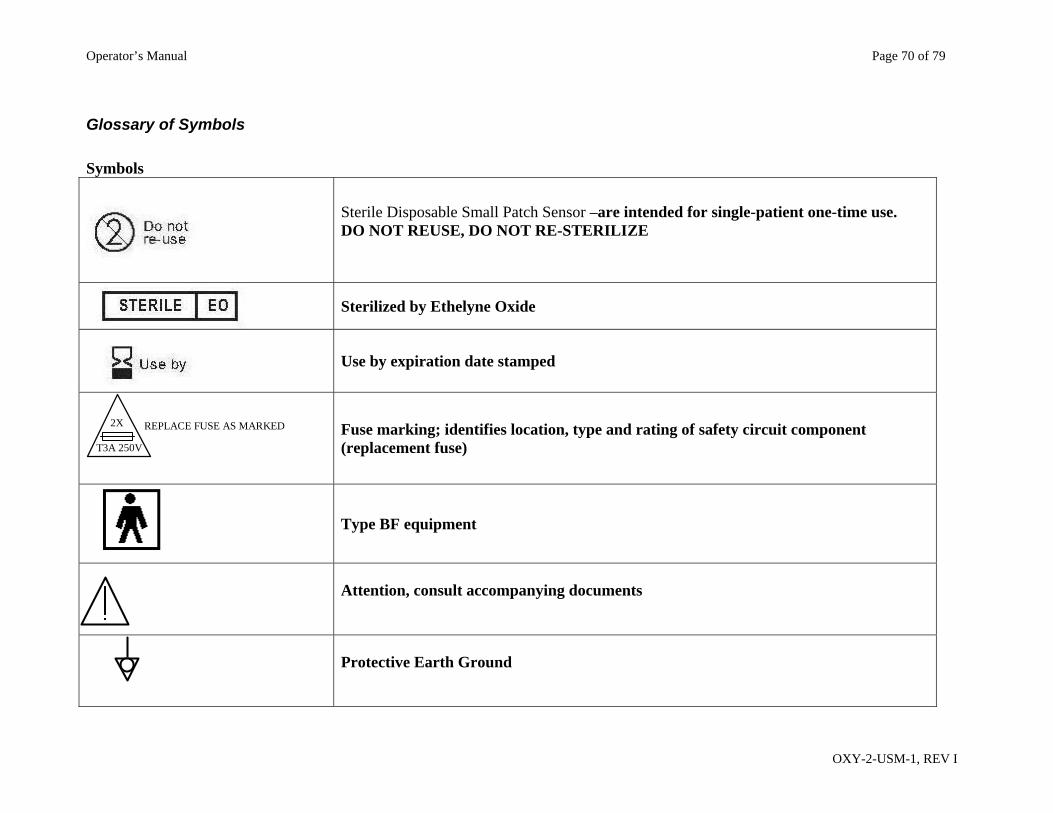
Glossary of Symbols
Symbols
Sterile Disposable Small Patch Sensor –are intended for single-patient one-time use. DO NOT REUSE, DO NOT RE-STERILIZE
Sterilized by Ethelyne Oxide
Use by expiration date stamped
Fuse marking; identifies location, type and rating of safety circuit component (replacement fuse)
Type BF equipment
Attention, consult accompanying documents
Protective Earth Ground
REPLACE FUSE AS MARKED 2X
T3A 250V
Operator’s Manual Page 71 of 79
OXY-2-USM-1, REV I
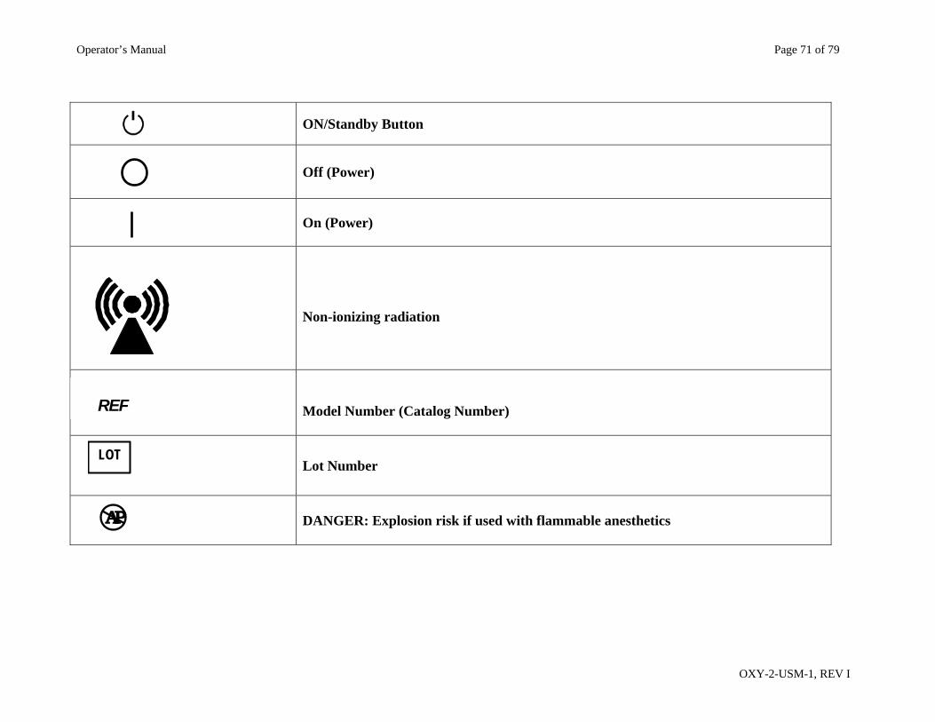
ON/Standby Button
Off (Power)
On (Power)
Non-ionizing radiation
Model Number (Catalog Number)
Lot Number
DANGER: Explosion risk if used with flammable anesthetics
REF
LOT
A P
Operator’s Manual Page 72 of 79
OXY-2-USM-1, REV I
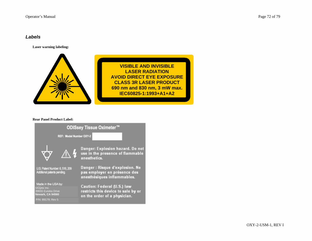
Labels Laser warning labeling:
Rear Panel Product Label:
VISIBLE AND INVISIBLE LASER RADIATION
AVOID DIRECT EYE EXPOSURE CLASS 3R LASER PRODUCT
690 nm and 830 nm, 3 mW max. IEC60825-1:1993+A1+A2
P/N: 89179; Rev 5
ViOptix Inc. 39655 Eureka Drive Newark, CA 94560
Operator’s Manual Page 73 of 79
OXY-2-USM-1, REV I
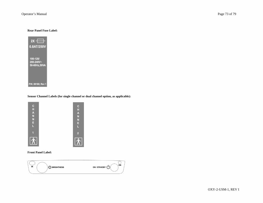
Rear Panel Fuse Label:
Sensor Channel Labels (for single channel or dual channel option, as applicable):
Front Panel Label:
Operator’s Manual Page 74 of 79
OXY-2-USM-1, REV I
Operator’s Manual Page 75 of 79
OXY-2-USM-1, REV I
Section VII. Troubleshooting
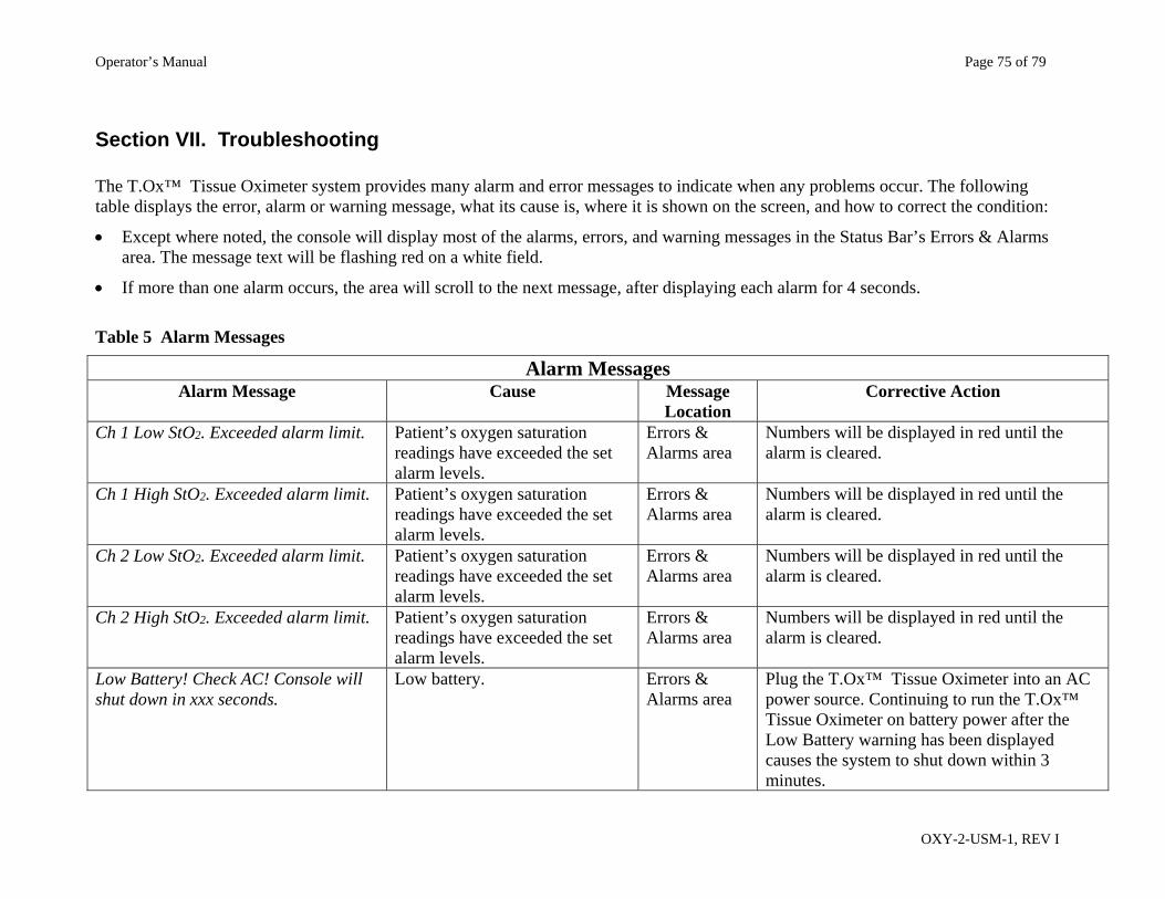
The T.Ox™ Tissue Oximeter system provides many alarm and error messages to indicate when any problems occur. The following table displays the error, alarm or warning message, what its cause is, where it is shown on the screen, and how to correct the condition:
Except where noted, the console will display most of the alarms, errors, and warning messages in the Status Bar’s Errors & Alarms area. The message text will be flashing red on a white field.
If more than one alarm occurs, the area will scroll to the next message, after displaying each alarm for 4 seconds.
Table 5 Alarm Messages
Alarm Messages Alarm Message Cause Message
Location Corrective Action
Ch 1 Low StO2. Exceeded alarm limit. Patient’s oxygen saturation readings have exceeded the set alarm levels.
Errors & Alarms area
Numbers will be displayed in red until the alarm is cleared.
Ch 1 High StO2. Exceeded alarm limit. Patient’s oxygen saturation readings have exceeded the set alarm levels.
Errors & Alarms area
Numbers will be displayed in red until the alarm is cleared.
Ch 2 Low StO2. Exceeded alarm limit. Patient’s oxygen saturation readings have exceeded the set alarm levels.
Errors & Alarms area
Numbers will be displayed in red until the alarm is cleared.
Ch 2 High StO2. Exceeded alarm limit. Patient’s oxygen saturation readings have exceeded the set alarm levels.
Errors & Alarms area
Numbers will be displayed in red until the alarm is cleared.
Low Battery! Check AC! Console will shut down in xxx seconds.
Low battery. Errors & Alarms area
Plug the T.Ox™ Tissue Oximeter into an AC power source. Continuing to run the T.Ox™ Tissue Oximeter on battery power after the Low Battery warning has been displayed causes the system to shut down within 3 minutes.
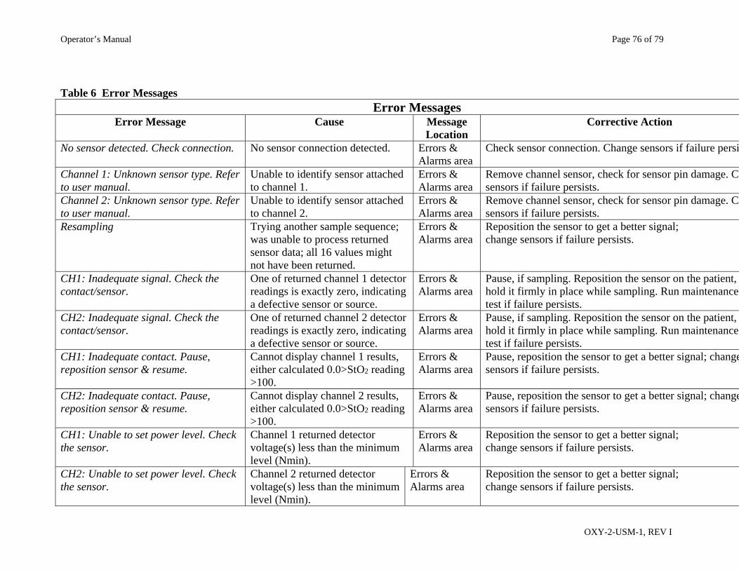
Operator’s Manual Page 76 of 79
OXY-2-USM-1, REV I
Table 6 Error Messages Error Messages
Error Message Cause Message Location
Corrective Action
No sensor detected. Check connection. No sensor connection detected. Errors & Alarms area
Check sensor connection. Change sensors if failure persi
Channel 1: Unknown sensor type. Refer to user manual.
Unable to identify sensor attached to channel 1.
Errors & Alarms area
Remove channel sensor, check for sensor pin damage. Chsensors if failure persists.
Channel 2: Unknown sensor type. Refer to user manual.
Unable to identify sensor attached to channel 2.
Errors & Alarms area
Remove channel sensor, check for sensor pin damage. Chsensors if failure persists.
Resampling Trying another sample sequence; was unable to process returned sensor data; all 16 values might not have been returned.
Errors & Alarms area
Reposition the sensor to get a better signal; change sensors if failure persists.
CH1: Inadequate signal. Check the contact/sensor.
One of returned channel 1 detector readings is exactly zero, indicating a defective sensor or source.
Errors & Alarms area
Pause, if sampling. Reposition the sensor on the patient, hold it firmly in place while sampling. Run maintenance test if failure persists.
CH2: Inadequate signal. Check the contact/sensor.
One of returned channel 2 detector readings is exactly zero, indicating a defective sensor or source.
Errors & Alarms area
Pause, if sampling. Reposition the sensor on the patient, hold it firmly in place while sampling. Run maintenance test if failure persists.
CH1: Inadequate contact. Pause, reposition sensor & resume.
Cannot display channel 1 results, either calculated 0.0>StO2 reading >100.
Errors & Alarms area
Pause, reposition the sensor to get a better signal; changesensors if failure persists.
CH2: Inadequate contact. Pause, reposition sensor & resume.
Cannot display channel 2 results, either calculated 0.0>StO2 reading >100.
Errors & Alarms area
Pause, reposition the sensor to get a better signal; changesensors if failure persists.
CH1: Unable to set power level. Check the sensor.
Channel 1 returned detector voltage(s) less than the minimum level (Nmin).
Errors & Alarms area
Reposition the sensor to get a better signal; change sensors if failure persists.
CH2: Unable to set power level. Check the sensor.
Channel 2 returned detector voltage(s) less than the minimum level (Nmin).
Errors & Alarms area
Reposition the sensor to get a better signal; change sensors if failure persists.
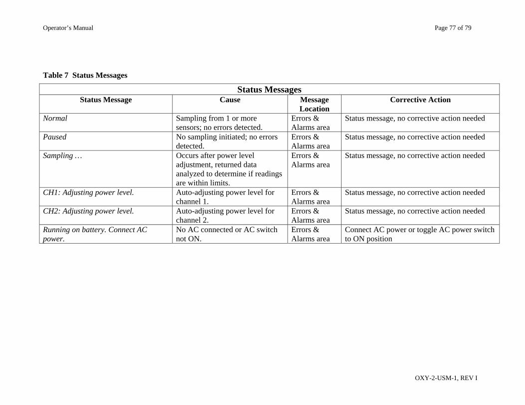
Operator’s Manual Page 77 of 79
OXY-2-USM-1, REV I
Table 7 Status Messages
Status Messages Status Message Cause Message
Location Corrective Action
Normal Sampling from 1 or more sensors; no errors detected.
Errors & Alarms area
Status message, no corrective action needed
Paused No sampling initiated; no errors detected.
Errors & Alarms area
Status message, no corrective action needed
Sampling … Occurs after power level adjustment, returned data analyzed to determine if readings are within limits.
Errors & Alarms area
Status message, no corrective action needed
CH1: Adjusting power level. Auto-adjusting power level for channel 1.
Errors & Alarms area
Status message, no corrective action needed
CH2: Adjusting power level. Auto-adjusting power level for channel 2.
Errors & Alarms area
Status message, no corrective action needed
Running on battery. Connect AC power.
No AC connected or AC switch not ON.
Errors & Alarms area
Connect AC power or toggle AC power switch to ON position
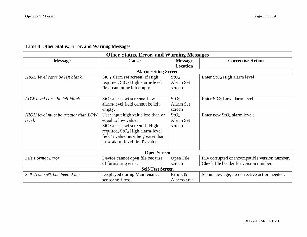
Operator’s Manual Page 78 of 79
OXY-2-USM-1, REV I
Table 8 Other Status, Error, and Warning Messages
Other Status, Error, and Warning Messages Message Cause Message
Location Corrective Action
Alarm setting Screen HIGH level can’t be left blank. StO2 alarm set screen: If High
required, StO2 High alarm-level field cannot be left empty.
StO2 Alarm Set screen
Enter StO2 High alarm level
LOW level can’t be left blank. StO2 alarm set screens: Low alarm-level field cannot be left empty.
StO2 Alarm Set screen
Enter StO2 Low alarm level
HIGH level must be greater than LOW level.
User input high value less than or equal to low value. StO2 alarm set screen: If High required, StO2 High alarm-level field’s value must be greater than Low alarm-level field’s value.
StO2 Alarm Set screen
Enter new StO2 alarm levels
Open Screen File Format Error Device cannot open file because
of formatting error. Open File screen
File corrupted or incompatible version number. Check file header for version number.
Self-Test Screen Self-Test. xx% has been done. Displayed during Maintenance
sensor self-test. Errors & Alarms area
Status message, no corrective action needed.
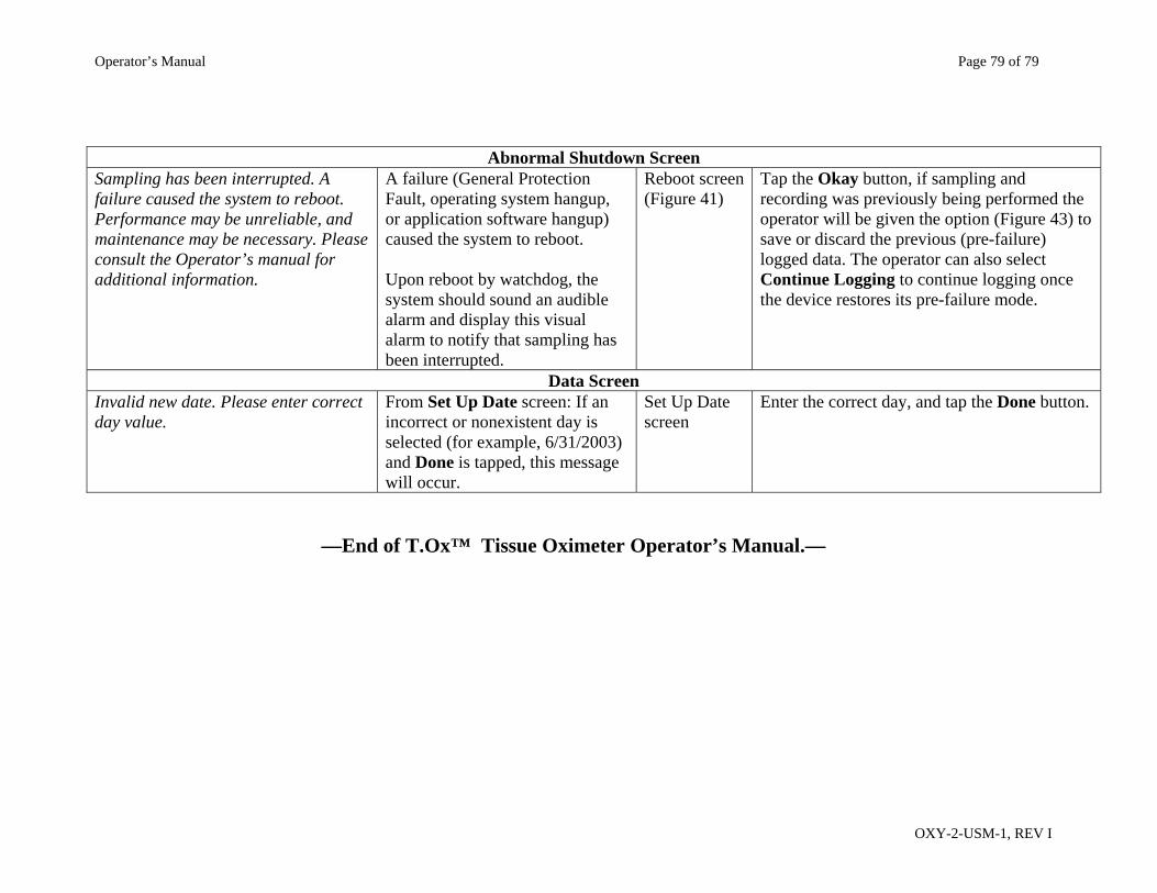
Operator’s Manual Page 79 of 79
OXY-2-USM-1, REV I
Abnormal Shutdown Screen
Sampling has been interrupted. A failure caused the system to reboot. Performance may be unreliable, and maintenance may be necessary. Please consult the Operator’s manual for additional information.
A failure (General Protection Fault, operating system hangup, or application software hangup) caused the system to reboot. Upon reboot by watchdog, the system should sound an audible alarm and display this visual alarm to notify that sampling has been interrupted.
Reboot screen (Figure 41)
Tap the Okay button, if sampling and recording was previously being performed the operator will be given the option (Figure 43) to save or discard the previous (pre-failure) logged data. The operator can also select Continue Logging to continue logging once the device restores its pre-failure mode.
Data Screen Invalid new date. Please enter correct day value.
From Set Up Date screen: If an incorrect or nonexistent day is selected (for example, 6/31/2003) and Done is tapped, this message will occur.
Set Up Date screen
Enter the correct day, and tap the Done button.
—End of T.Ox™ Tissue Oximeter Operator’s Manual.—