Embed Size (px)
Citation preview
Oxidative trends of TiO2—Hole trapping at anatase and rutilesurfaces†
Paweł Zawadzki,∗a§ Anders Bo Laursen,b Karsten Wedel Jacobsen,a Søren Dahlb and Jan Rossmeisla
Supplemental Material
Self-trapping energies in surface layers
Strong electron interaction with lattice distortion can lead toelectron self-trapping, i.e. formation of a localized boundstate. The self-trapping energy is defined as a difference be-tween the energy of the delocalized state at zero distortion(perfect lattice) ED(Q = 0) and the energy of the localized(trapped) state at its equilibrium distortion ET(Q = QT). Insurface layers the self-trapping energy depends both on thetype of surface termination S and the exact location of the trap-ping site z:
εT(S,z) = ET(QT;S,z)−ED(Q = 0;S). (1)
In order to position such trapping level in the band gap com-mon reference energy is needed as the energy of the delocal-ized state can be different for different surface terminationsand the bulk band edges are not well defined for a finite thick-ness surface slab. Using the fact that at large depth below thesurface the self-trapping energy must converge to the value inthe bulk:
limz→∞
εT(S,z) = εBT , (2)
we find that the electron (hole) self-trapping level relative theconduction (valence) band maximum in the bulk takes theform:
εT(S,z) = εBT +ET(QT;S,z)−ET(QT;S,z→ ∞). (3)
In Ref.1 we calculated εBT to be 0.05 eV and 0.2 eV for rutile
and anatase, respectively. To calculate ET(QT;S,z→ ∞) weaverage ∆-SCF energy ET(QT;S,z) of the four [two in caseof anatase (100)] most deeply positioned relative to surfacehole states in a unit cell sufficiently large for ET(QT : S,z) toshow convergence behaviour. Fig. 1 and Fig. 3 show self-trapping energy profiles aligned with the self-trapping energyin the bulk. In Fig. 5 we plot the self-trapping energy profilesfor different unit cell sizes.
Delocalization Error
Calculation of self-trapping energies with semi-localexchange-correlation DFT, such as PBE DFT, is problematicas the method tends to favour energetically delocalizedstates—the infamous many electron self-interaction2 or
delocalization error3. In Eq. 3 the only term where theenergy difference between delocalized and localized state iscalculated is the bulk self-trapping energy εB
T . We assume thatthe energy differences between localized states are correct andtake the value of the bulk hole self-trapping energy correctedfor the delocalization error from Ref.1. We further note thatthe relative self-trapping energies for different facades of onephase are independent on the choice of reference energy as itonly shifts the self-trapping energies by a constant.
Modeling self-trapped hole with ∆-SCF
The linear expansion ∆-SCF is an approximate technique tocalculate excited state energies that uses4
• ground state energy functional,
• approximate excited state density.
The excited state density is constructed by adding or subtract-ing the density of an orbital |φ〉 expanded in KS states whileconserving the total number of electrons:
ρ(r) = ∑n
fN±1(εn)|ψn(~r)|2∓|ψ(~r)|2 (4)
where f is Fermi-Dirac distribution and
|ψ〉= ∑n〈ψn|φ〉|ψn〉. (5)
The Kohn-Sham equations are then solved till self-consistently is achieved.The difficult part in application of ∆-SCF is choice of the or-bital |φ〉 that will lead to excited state density. A physicalinsight into the nature of the excited state is necessary.To construct localized hole state in TiO2 we use the oxygenp-like orbital1 perpendicular to the OTi3 building block ofTiO2. As discussed in Ref.1 such choice is consistent withexperimental EPR data, electronic structure and symmetry ar-guments. With electron density constrained by Eq. 4 and Eq. 5(the expansion is over the states below the Fermi level) we re-laxed electronic and atomic structures. Convergence of theenergy and the maximum force of 0.05 eV/A was achievedin most cases. In some, however, the hole is unstable andthe above convergence criterion has not been attained there-fore there we report local minima. These does not change theoverall picture as unstable states do not trap holes.
1–4 | 1
Electronic Supplementary Material (ESI) for Energy & Environmental ScienceThis journal is © The Royal Society of Chemistry 2012
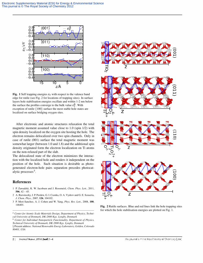
Fig. 1 Self trapping energies εT with respect to the valence bandedge for rutile (see Fig. 2 for locations of trapping sites). In surfacelayers hole stabilisation energies oscillate and within 1-2 nm belowthe surface the profiles converge to the bulk value εB
T . Withexception of rutile {100} surface the most stable hole states arelocalized on surface bridging oxygen sites.
After electronic and atomic structures relaxation the totalmagnetic moment assumed value close to 1.0 (spin 1/2) withspin density localized on the oxygen site hosting the hole. Theelectron remains delocalized over two spin channels. Only incase of rutile (001) surface the total magnetic moment wassomewhat larger (between 1.0 and 1.8) and the additional spindensity originated form the electron localization on Ti atomson the non-relaxed part of the slab.The delocalized state of the electron minimizes the interac-tion with the localized hole and renders it independent on theposition of the hole. Such situation is desirable as photo-generated electron-hole pairs separation precedes photocat-alytic processes5.
References1 P. Zawadzki, K. W. Jacobsen and J. Rossmeisl, Chem. Phys. Lett., 2011,
506, 42 – 45.2 A. Ruzsinszky, J. P. Perdew, G. I. Csonka, O. A. Vydrov and G. E. Scuseria,
J. Chem. Phys., 2007, 126, 104102.3 P. Mori-Sanchez, A. J. Cohen and W. Yang, Phys. Rev. Lett., 2008, 100,
146401.
a Center for Atomic-Scale Materials Design, Department of Physics, Techni-cal University of Denmark, DK-2800 Kgs. Lyngby, Denmarkb Center for Individual Nanoparticle Functionality, Department of Physics,Technical University of Denmark, DK-2800 Kgs. Lyngby, Denmark§ Present address: National Renewable Energy Laboratory, Golden, Colorado80401, USA
Fig. 2 Rutile surfaces. Blue and red lines link the hole trapping sitesfor which the hole stabilisation energies are plotted on Fig. 1.
2 | 1–4
Electronic Supplementary Material (ESI) for Energy & Environmental ScienceThis journal is © The Royal Society of Chemistry 2012

Fig. 3 Self trapping energies εT with respect to the valence bandedge for anatase (see Fig. 4 for locations of trapping sites). Insurface layers hole stabilisation energies oscillate and within 1-2 nmbelow the surface the profiles converge to the bulk value εB
T .
4 J. Gavnholt, T. Olsen, M. Engelund and J. Schiotz, Phys. Rev. B, 2008, 78,075441.
5 M. A. Henderson, Surf. Sci. Rep., 2011, 66, 185–297.
Fig. 4 Anatase surfaces. Blue and red lines link the hole trappingsites for which the hole stabilisation energies are plotted on Fig.3.
1–4 | 3
Electronic Supplementary Material (ESI) for Energy & Environmental ScienceThis journal is © The Royal Society of Chemistry 2012

Fig. 5 Self-trapping energies εT calculated with different cell sizes.
Fig. 6 Convergence of the work function with the slab thickness.
4 | 1–4
Electronic Supplementary Material (ESI) for Energy & Environmental ScienceThis journal is © The Royal Society of Chemistry 2012


![Hydrostatic and [001] Uniaxial Pressure on Anatase TiO by](https://img.pdfslide.us/doc/110x75/623597795594cb0bd451d269/hydrostatic-and-001-uniaxial-pressure-on-anatase-tio-by-.jpg)