Embed Size (px)
Citation preview

HAL Id: tel-00742470https://tel.archives-ouvertes.fr/tel-00742470v2
Submitted on 7 May 2010
HAL is a multi-disciplinary open accessarchive for the deposit and dissemination of sci-entific research documents, whether they are pub-lished or not. The documents may come fromteaching and research institutions in France orabroad, or from public or private research centers.
L’archive ouverte pluridisciplinaire HAL, estdestinée au dépôt et à la diffusion de documentsscientifiques de niveau recherche, publiés ou non,émanant des établissements d’enseignement et derecherche français ou étrangers, des laboratoirespublics ou privés.
Oxidation of phenol and cresol by electrochemicaladvanced oxidation method in homogeneous medium :
application to treatment of a real effluent of aeronauticalindustry
Marcio Pimentel
To cite this version:Marcio Pimentel. Oxidation of phenol and cresol by electrochemical advanced oxidation method inhomogeneous medium : application to treatment of a real effluent of aeronautical industry. Other.Université Paris-Est, 2008. English. <NNT : 2008PEST0271>. <tel-00742470v2>

Université Paris-Est Marne-La-Vallée Institut Francilien des Sciences Appliquées (IFSA)
Laboratoire Géomatériaux et Géologie de l'Ingénieur
THÈSE
pour obtenir le grade de Docteur de l’Université Paris-Est Marne-la-Vallée
Spécialité : Sciences et Techniques de l'Environnement
présentée et soutenue publiquement par
Marcio PIMENTEL le 24 septembre 2008
Etudes de l'oxydation de phénol et crésols par l'oxydation électrochimique avancée en milieu homogène. Application au
traitement d'effluent de l'industrie aéronautique
Phenol and cresols treatment in aqueous solution by electro-Fenton process: Application to the mineralization of aeronautic wastewater industry.
Directeur de thèse : Prof. Mehmet A. OTURAN
Jury:
Président: Prof. Jean Guillaume EON Université Fédérale de Rio de Janeiro Rapporteurs: Dr. Maurice MÉDEBIELLE Université Lyon 1 Prof. Geraldo Lippel SANT´ANNA JR. Université Fédérale de Rio de Janeiro Examinateurs: Prof. Márcia W. Carvalho DEZOTTI Université Fédérale de Rio de Janeiro Dr. Nihal OTURAN Université Paris-Est Marne-la-Vallée Prof. Tito Livio Moitinho ALVES Université Fédérale de Rio de Janeiro © UMLV

ii
Remerciements
Cette thèse a été réalisée par une co-tutelle entre l’Université Féderal de Rio de Janeiro et
l'Université Paris-Est de Marne-La-Vallée au laboratoire des Géomatériaux et Géologie de
l'Ingénieur au sein de l’équipe chimie de l'environnement avec le financement de l’Armée de l’Air
Brésilienne.
Je remercie l’Armée de l’Air Brésilienne par la confiance qui m'a été accordée.
Je tiens à dire un grand merci à Mehmet A. Oturan, Professeur à l'université de Marne-la-Vallée,
pour les conseils précieux, ses commentaires et tout aide qu'il m'a apporté au cours de ce travail.
Je tiens à dire merci aussi à Marcia Dezotti, Professeur à l’Université Fédérale de Rio de Janeiro,
pour les conseils et l'aide qu'il m'a apporté au cours de ce travail.
Je remercie très chaleureusement Nihal Oturan pour toute l'aide qu'elle m'a apportée pour mes
expériences.
Un grand merci à mon épouse Marcela pour son amour et patience pendant tout ce temps.
Je voudrais également remercier toute l'équipe du laboratoire Géomatériaux, surtout les thésards
et stagiaires, pour leur bonne humeur, leurs histoires et, particulierment, les commentaires sur
football pendant les pauses. Merci à Beytül, Nacho, Samiha, Mababa, Aida, Mustapha, Minir. Vous
étiez là quand j'en avais besoin et même pour les autreschoses.

iii
Abstract of Thesis presented to COPPE/UFRJ as a partial fulfillment of the requirements for the
degree of Doctor of Science (D. Sc.)
Phenol and cresols treatment in aqueous solution by “electro-fenton” process:
Application to the mineralization of aeronautic wastewater industry.
Marcio Antonio da Silva Pimentel
September/2008
Advisors: Mehmet A. Oturan
Márcia Walquíria de Carvalho Dezotti
Department: Chemical Engineering
The present work verified the efficiency of electro-Fenton to destroy phenolic compounds
present in Stripping Aircraft Wastewater. This research aimed to elucidate the influence of the
catalyst nature, its concentration and of electric current density in efficiency of electro-Fenton
process using an indivisible cell with a carbon felt cathode and platinum or borod doped diamond
anodes. The experiments compared the effect of these variables to destroy phenol, cresols and
their intermediates. The compounds and many intermediates formed were identified in High
Perfomance Liquid Chromatograph and allowed obtaining apparent and/or absolute constants and
simplified degradation mechanisms. In optimum conditions, measures of Total Organic Carbon
showed high mineralization rates. At the end, the application of electro-Fenton process to high
organics loads of real Stripping Aircraft wastewater allowed obtaining almost complete
mineralization replacing Pt anode by Boron Doped Diamond.
Key words: degradation, phenol, cresols, electro-Fenton.

iv
SUMMARY
INTRODUCTION............................................................................................................................................................. 11
CHAPTER I: BIBLIOGRAPHICAL REVIEW.................. ................................................................................................ 14
1.1 AIRCRAFT EFFLUENT CHARACTERIZATION ............................................................................................................. 15 1.2 TREATMENT TECHNIQUES TO REMOVE PHENOL AND CRESOLS ............................................................................... 21
1.2.1 Biological Processes.................................................................................................................................. 21 1.2.2 Conventional Physico-Chemical Processes.............................................................................................. 22
1.2.2.1 Activated Carbon Absorption ..................................................................................................................................... 23 1.2.2.2 Chemical precipitation................................................................................................................................................ 23 1.2.2.3 Conventional chemical oxidation............................................................................................................................ 23
1.2.3 Advanced Oxidative Processes (AOPs) .................................................................................................... 24 1.2.3.1 Conventional AOPs.................................................................................................................................................... 24 1.2.3.2 Electrochemical Advanced Oxidation Processes ....................................................................................................... 28
1.3 INFLUENTIAL PARAMETERS IN THE ELECTRO-FENTON PROCESS ............................................................................. 37 1.3.1 Electrode nature ........................................................................................................................................ 37 1.3.2 pH .............................................................................................................................................................. 38 1.3.3 Nature and Catalyst Concentration ........................................................................................................... 39 1.3.4 Effect of the medium.................................................................................................................................. 40 1.3.5 Electrolytes ................................................................................................................................................ 41 1.3.6 Dissolved Oxygen concentration ............................................................................................................... 42 1.3.7 Current Density.......................................................................................................................................... 43 1.3.8 Temperature .............................................................................................................................................. 45 1.3.9 Transport Phenomena............................................................................................................................... 45
CHAPTER II: MATERIALS AND METHODES ................. ............................................................................................. 48
2.1 CHEMICAL PRODUCTS ......................................................................................................................................... 49 2.2. SOLUTIONS PREPARED........................................................................................................................................ 49 2.3. ANALYTICAL TECHNIQUES.................................................................................................................................... 50
2.3.1 High performance liquid chromatography (HPLC) .................................................................................... 50 2.3.2 Total Organic Carbon (TOC) ..................................................................................................................... 50
2.4 ELECTROCHEMICAL REACTOR.............................................................................................................................. 51 2.5 EXPERIMENTAL PROCEDURES.............................................................................................................................. 52
2.5.1 Obtention of absolute rate constants......................................................................................................... 52 2.5.2 Influence of the catalyst nature.................................................................................................................. 53 2.5.3 Effect of catalyst concentration and anodic oxidation ............................................................................... 54 2.5.4 Identification of intermediates and oxidation reactions.............................................................................. 54 2.5.5 Effect of current density and volume ......................................................................................................... 55 2.5.6 Real wastewater treatment ........................................................................................................................ 55

v
CHAPTER III: ELECTRO-FENTON TREATMENT OF PHENOL, CR ESOLS AQUEOUS SOLUTIONS AND REAL
“STRIPPING PROCESS” EFFLUENTS ...................... .................................................................................................. 57
3.1 KINETICS STUDIES ............................................................................................................................................... 58 3.2 INFLUENCE OF THE CATALYST NATURE.................................................................................................................. 60 3.3 EFFECT OF CATALYST CONCENTRATION AND ANODIC OXIDATION ............................................................................ 62 3.4 IDENTIFICATION OF INTERMEDIATES...................................................................................................................... 65
3.4.1 Evolution of aromatic intermediates .......................................................................................................... 65 3.4.2. Evolution of carboxilic acids ...................................................................................................................... 69
3.4.2.1. Identified carboxylic acids in phenol oxidation .......................................................................................................... 69 3.4.2.2 Idenfified acids in cresols oxidation............................................................................................................................ 74
3.5 INFLUENCE OF CURRENT DENSITY AND VOLUME .................................................................................................... 79 3.6 APPLICATION OF ELECTRO-FENTON PROCESS IN AIRCRAFT STRIPPING PROCESS EFFLUENT .................................... 83
CHAPTER IV: CONCLUSION ............................. ........................................................................................................... 86
REFERENCES................................................................................................................................................................ 89
GLOSSARY ........................................... ....................................................................................................................... 100
ANNEXES ..................................................................................................................................................................... 102
vi
LIST OF FIGURES
Figure 1. Typical flowchart from washing process. ........................................................................................................ 15 Figure 2. Typical flowchart of stripping process. ............................................................................................................ 16 Figure 3. Typical flowchart of pre-painting process........................................................................................................ 16 Figure 4. Fuselage stripping of T-25 aircraft at PAMA-LS. ............................................................................................ 17 Figure 5. Reaction pathway during electrochemical phenol degradation. Experimental conditions: anodic oxidation in
indivisible cells with cathodes of stainless steel and anodes of Ti/SnO2-Sb, Ti/RuO2 or Pt (LI et al. 2005). . 31 Figure 6. Electro-Fenton process (Source: adapted from OTURAN e PINSON, 1992)................................................. 33 Figure 7. Proposed reaction sequence for the electro-Fenton and solar photoelectro-Fenton degradations of o-cresol,
m-cresol and p-cresol in acid medium using a BDD anode. The hydroxyl radical is denoted as ●OH or
BDD(●OH) when it is formed from Fenton’s reaction or at the BDD surface from water oxidation, respectively
(FLOX et al., 2007).......................................................................................................................................... 36 Figure 8. Triclosan degradation (V0 = 200 mL, C0 = 5 mg triclosan/L, pH = 3 e I = 60mA) in aqueous solution
containing 0.05M of Na2SO4 and 0.20 mM of Fe3+. Electrochemical cells: (●) Pt/FC, (∎) BDD/FC, (▲) Pt/O2
and (◆) BDD/O2 (SIRÉS et al., 2007b). .......................................................................................................... 37
Figure 9. Change of accumulated H2O2 concentration with time during electrolysis of 50 mL of 0.1 M phosphate buffer
solution in an undivided cell of Pt/graphite at: (a) pH=3.0, (b) pH=4.0 (CHEN et al., 2003). ......................... 38 Figure 10. Evolution of COD (filled symbols) and phenol concentration (outlined symbols) vs. electrical charge for
coupled oxidation at various iron concentrations (∎: 5. ◆: 50 e ●: 200 mg/L). Operating conditions: 100
A/m2, 20 mg/L O2, and pH 3 (FOCKEDEY and VAN LIERDE, 2002)............................................................. 40
Figure 11. Degradation kinetics of methyl parathion in several acidic media by electro-Fenton process: (◦): perchloric,
(△): sulfuric, (▫): hydrochloric, and (◇):nitric media. C0 = 0.13 mM, [Fe3+] = 0.1 mM, V = 0.150 L, I = 100 mA,
DIAGNE et al. (2007). ..................................................................................................................................... 40 Figure 12. Effect of eletrolytes on blue methylene degradation by Fenton process (DUTTA et al., 2001).................... 41 Figure 13. Evolution of COD (filled symbols) and phenol concentration (outlined symbols) vs. electrical charge for
coupled oxidation at various dissolved oxygen concentration (∎: 4 mg/L, ▲: 10 mg/L, ●: 20 mg/L, and �: 27
mg/L). Operating conditions: 100A/m2, 50 mg/L Fe, and pH 3 (FOCKEDEY and VAN LIERDE, 2002). ....... 42
Figure 14. Effect of current increase (▼: 60. ∎: 100. ●: 200 e ▲: 300 mA) on kinetics degradation of diuron herbicide
in aqueous solution containing 0.05M Na2SO4 and 0.5mM Fe2+ in an indivisible Pt/CF cell. Experimental
conditions: cathodic surphace equal to 60 cm2 and volume equal to 150 ml (EDELAHI et al., 2004). .......... 43 Figure 15. Electrochemical reactor used in electro-Fenton experiments. ...................................................................... 51
Figure 16. Determination of phenol absolute constant. Experimental conditions: V0 = 125 mL, I = 60 mA, [phenol]i ≅
[4HBA]i ≅ 0.5 mM, [Fe2+] = 0.1 mM, reaction time = 30 minutes and Pt (1.5 cm x 2 cm) / CF (7 cm x 8 cm x
0,6 cm) electrodes........................................................................................................................................... 59

vii
Figure 17. Determination of o-cresol absolute constant. Experimental conditions: V0 = 125 mL, I = 60 mA, [phenol]i ≅
[4HBA]i ≅ 0.5 mM, [Fe2+] = 0.1 mM, reaction time = 30 minutes and Pt (1.5 cm x 2 cm) / CF (7 cm x 8 cm x
0,6 cm) electrodes........................................................................................................................................... 59 Figure 18. TOC removal with electrolysis time for the mineralization of 0.33 mM (TOC0 = 24 mg L-1) phenol aqueous
solution with different catalysts during electro-Fenton treatment: [Fe2+]: 0.05 mM (-□-), 0.10 mM (-�-), 1.00
mM (-∆-); [Co2+]: 0.05 mM(-▲-), 0.10 mM (--), 1.00 mM (-♦-); [Mn2+]: 0.10 mM (---), 0.50 mM (◊), 1.0 mM (-
�-); [Cu2+]: 1.0 mM (-+-), 5 mM (-�-),10 mM (-X-). Experimental conditions: Initial volume (V0) = 330 mL, I =
100 mA, pH = 3 and Pt (1.5 cm x 2 cm) / CF (7 cm x 8 cm x 0.6 cm) electrodes. ......................................... 61 Figure 19. Effect of catalyst (Fe2+) concentration on the degradation kinetics of phenol at pH 3 during current
controlled electrolysis by electro-Fenton process at 60 mA: (-△-): [Fe2+] = 0 mM (R2=0.997); (-□-): [Fe2+] =
0.05 mM (R2=0.997), (-■-); [Fe2+] = 0.1 mM (R2=0.998); (-●-): [Fe2+] = 0.25 mM (R2=0.999); (-▲-): [Fe2+] =
0.5 mM (R2=0.998); (-�-): [Fe2+] = 1.0 mM, (R2=0.997). Experimental conditions: V0=125 mL and Pt (1.5 cm
x 2 cm) / CF (7 cm x 8 cm x 0,6 cm) electrodes. ............................................................................................ 63 Figure 20. Effect of catalyst (Fe2+) concentration on the degradation kinetics of o-cresol: (-□-) [Fe2+] = 0.05 (R2=0.997),
(-■-) [Fe2+] = 0.10 (R2=0.999), (-▲-) [Fe2+] = 0.25 (R2=0.997) and (-△-) [Fe2+] = 1 mM (R2=0.996); m-cresol:
(-○-) [Fe2+] =0.10 mM (R2=0.999) and p-cresol: (-●-) [Fe2+] = 0.10 mM (R2=0.998) at pH 3 during current
controlled electrolysis at 60 mA by electro-Fenton process. Experimental conditions: V0=125 mL and Pt (1.5
cm x 2 cm) / CF (7 cm x 8 cm x 0,6 cm) electrodes. ...................................................................................... 64 Figure 21. Time-course of aromatic intermediates: (-■-) p-benzoquinone; (-□-) catechol and (-▲-) hydroquinone during
the degradation of 1.05 mM phenol aqueous solution by electro-Fenton process. Experimental conditions:
[Fe2+] = 0.10 mM, V0 = 125 mL, pH = 3 and I = 60 mA and Pt (1.5 cm x 2 cm) / CF (7 cm x 8 cm x 0,6 cm)
electrodes........................................................................................................................................................ 66 Figure 22. Proposed reaction mechanisms for hydroxyl addition and hydrogen atom abstraction during phenol
oxidation by ●OH radicals................................................................................................................................ 67 Figure 23. Time-course of aromatic intermediates: (-■-) 3-methyl-catechol and (-▲-) methyl-hydroquinone during the
degradation of 1.05 mM o-chresol aqueous solution by electro-Fenton process. Experimental conditions:
[Fe2+] = 0.10 mM, V0 = 125 mL, pH = 3 and I = 60 mA and Pt (1.5 cm x 2 cm) / CF (7 cm x 8 cm x 0,6 cm)
electrodes........................................................................................................................................................ 68 Figure 24. Proposed reactions mechanisms of hydroxyl addition on o-chresol aromatic ring by electro-Fenton process.
........................................................................................................................................................................ 68 Figure 25. Evolution of carboxylic acids identified during oxidation of phenol by electro-Fenton treatment: maleic (-■-),
fumaric (-□-), succinic (-△-), glyoxylic (-○-), formic (-●-) and oxalic (-◇-) acids. Experimental conditions:
[Phenol]0 = 2.50 mM, [Fe2+] = 0.10 mM, [Na2SO4] = 50 mM, V0 = 125 mL, I = 200 mA, pH= 3.0 and Pt (1.5
cm x 2 cm) / CF (7 cm x 8 cm x 0,6 cm) electrodes. ...................................................................................... 69
Figure 26. Evolution of carboxylic acids identified (glioxylic: ○, fumaric: □, pyruvic: ▲, malonic: ∗, succinic: △, maleic:
■ and oxalic: ◇) during benzoquinone (a), hydroquinone (b) and catechol (c) degradation by electro-Fenton
process. Experimental conditions: I = 200 mA, V0 = 125 mL, C0 = 2.5 mM, [Fe2+] = 0.1 mM, [Na2SO4] = 50
mM, pH= 3.0 and Pt (1.5 cm x 2 cm) / CF (7 cm x 8 cm x 0,6 cm) electrodes. .............................................. 71

viii
Figure 27. Proposed reactions mechanisms of maleic production due to hydroxyl attack and catechol aromatic ring
cleavage by electro-Fenton process. .............................................................................................................. 72 Figure 28. General reaction sequence proposed for the mineralization of phenol in aqueous acid medium by hydroxyl
radicals generated in electro-Fenton process................................................................................................. 73 Figure 29. Evolution of carboxylic acids identified during oxidation of o-cresol by electro-Fenton treatment: fumaric:
(□), succinic: (△), maleic: (■), piruvic: (▲), glioxylic: (○), oxalic: (◇), acetic: (◆) and formic: (●) acids.
Experimental conditions: [o-chresol]0 = 2.50 mM, [Fe2+] = 0.10 mM, [Na2SO4] = 50 mM, V0 = 125 mL, I = 200
mA, pH= 3.0 and Pt (1.5 cm x 2 cm) / CF (7 cm x 8 cm x 0,6 cm) electrodes. .............................................. 74 Figure 30. Proposed reactions mechanisms of maleic and pyruvic production due to hydroxyl attack and 3-methyl-
catechol aromatic ring cleavage by electro-Fenton process........................................................................... 75 Figure 31. General reaction sequence proposed for the mineralization of o-cresol in aqueous acid medium by hydroxyl
radicals generated by electro-Fenton process................................................................................................ 76
Figure 32. Evolution of carboxylic acids identified (succinic: △, malonic: ∗, piruvic: ▲, glycolic: x, glyoxylic: ○, acetic:
◆, oxalic: ◇ and formic: ●) during oxidation of m-chresol by electro-Fenton treatment. Experimental
conditions: I = 200 mA, V0 = 125 mL, C0 = 2.5 mM, [Fe2+] = 0.1 mM, [Na2SO4] = 50 mM, pH= 3.0 and Pt (1.5
cm x 2 cm) / CF (7 cm x 8 cm x 0,6 cm) electrodes. ...................................................................................... 77
Figure 33. Evolution of carboxylic acids identified (glycolic: x, malonic: ∗, formic: ●, glyoxylic: ○, acetic: ◆, piruvic: ▲
e oxalic: ◇) during oxidation of p-cresol by electro-Fenton treatment. Experimental conditions: I = 200 mA,
V0 = 125 mL, C0 = 2.5 mM, [Fe2+] = 0.1 mM, [Na2SO4] = 50 mM, pH= 3.0 and Pt (1.5 cm x 2 cm) / CF (7 cm
x 8 cm x 0,6 cm) electrodes. ........................................................................................................................... 78
Figure 34. TOC removal during phenol (○, △, ▲, □) and o-cresol (x) degradation by electro-Fenton process changing
the volume of reaction medium (150 mL: ○, ▲ and □; 400 mL: x and △) and/or current density (j = 0
mA/cm2: ○; j = 2.7 mA/cm2: □ ; j = 5.4 mA/cm2: x, △ and ▲). Experimental conditions: I = 300 mA, C0 ≅ 1
mM (with theoretical TOC0 = 72 mg/L), [Fe2+] = 0.1 mM, [KCl] = 75 mM, pH= 3.0 and Pt (1.5 cm x 2 cm) / CF
(7 cm x 8 cm x 0,6 cm: △; ▲, x and 7 cm x 16 cm x 0,6 cm: ○, □) electrodes. .............................................. 80
Figure 35. Effect of current increase (▲: I = 250 mA, j = 4.5 mA/cm2 and △: I = 500 mA, j = 9 mA/cm2) on
mineralization of solution containing equimolar concentrations of phenol and cresols ([phenol]0 = [o-cresol]0
= [m-cresol]0 = [p-cresol]0 ≅ 1 mM). Experimental conditions: TOC0 ≅ 324 mg/L, V0 = 100 mL, [Fe2+] = 0.1
mM e [KCl] = 75 mM, pH= 3.0 and Pt (1.5 cm x 2 cm) / CF (7 cm x 8 cm x 0,6 cm) electrodes.................... 82 Figure 36. TOC removal from real effluent by electro-Fenton process (I = 500 mA, V0 = 250 mL and pH = 2.9 - 3) in
electrochemical cells of Pt (1.5 cm x 2 cm) / CF (17 cm x 4 cm x 0.6 cm): (○) TOC0 = 5300 mg/L and BDD (4
cm x 6 cm) /CF (17 cm x 4 cm x 0.6 cm): (■) TOC0 = 5280 mg/L; (▲) TOC0 = 5312 mg/L and (●) TOC0 =
4950 mg/L. Experimental conditions: addition of 0.2 mM of Fe2+ (○, ■); addition of 0.2 mM of Fe2+ with
previous removal of chrome (●) and without addition of iron (▲)................................................................... 83

ix
LIST OF TABLES
Table 1. Chemical analysis from wastewater produced at PAMA-LS ............................................................................ 18
Table 2. Chemical analysis from wastewater produced at PAMA- GL ........................................................................... 19
Table 3. Some physical and chemical properties of phenol and cresols (FIESER, 1930; VIDIC, SUIDAN and
BRENNER, 1993; UNEP, ILO and WHO, 1994, 1995) .................................................................................... 21
Table 4. Efficiencies obtained during biological treatment of phenol and cresols .......................................................... 22
Table 5. Reactions of production of •OH by AOP’s. ....................................................................................................... 25
Table 6. Aromatic intermediates identified during phenol and cresols degradation by AOP’s....................................... 26
Table 7. Carboxylic acids identified during phenol and cresols degradation by AOP’s.................................................. 26
Table 8. Efficiencies obtained during phenol (Ph) and cresols (Cr) degradation by AOP’s. .......................................... 27
Table 9. Name, use, formula and purity of chemical substances used in this work ....................................................... 49
Table 10. Metal ions and salt concentrations used during catalyst’s experiments......................................................... 54
Table 11. Retention times obtained during compounds identification ............................................................................ 55
Table 12. Products identified in earlier stages of carboxylic acids degradation by electro-Fenton process. Experimental
conditions: [C0] = 0.5 mM, [Fe2+] = 0.1 mM, I = 60 mA, V0 = 330 mL, pH = 3 and Pt / CF electrodes. .......... 72

x
ABREVIATIONS
AOPs – Advanced Oxidative Processes
HPLC – High performance liquid chromatography
TOC – Total Organic Carbon
Fig. – Figure
UNEP – United Nations Environment Programe

11
INTRODUCTION

12
Safety is one of the most important requirements in aeronautical industry. From the
mechanical point of view, it is frequently necessary to remove all paint from the fuselage in order to
verify the existence of corrosion points. Notwithstanding, the paint removers used in these
processes have high concentrations of phenols and cresols, which are pollutants of considerable
environmental risk. Releasing this waste in natura in the aqueous media constitutes environmental
crime, because the waters generated from the washing (effluents) contain phenols’ concentrations
much higher than the release patterns defined by the environmental agencies (FRANCE, 2001;
BRAZIL, 2005). The aeronautical activity also requires the use of extremely resistant paints, what
makes impossible the use of less toxic removers. Hence, the end of pipe treatment becomes
necessary, even if it means a higher cost.
Many studies show that the biological processes may degrade many effluents, which contain
phenolic substances, satisfactorily. However, the acclimatization is very difficult in waters with high
concentration of residuals; the retention time becomes very high (usually days), specific nutrients
are needed, and the biggest part of aromatic intermediaries is persistent. (AHAMAD and KUNHI,
1999; PERRON and WELANDER, 2004).
Aiming at meeting the environmental legislation demands, which grow more and more severe
since the 90’s, a number of alternative techniques for residual water treatment were developed,
these were called advanced oxidation processes (AOPs). The AOPs involve the in situ generation
of hydroxyl radical (•OH), a very strong oxidizing agent, capable of destroying the organic
molecules present in contaminated waters, converting them successively into carbon dioxide and
water (BAIRD, 2002). Therefore, it is a clean technology that minimizes the transference of the
pollutant mass from the liquid phase to the solid one. Moreover, the reactions between the radicals •OH and the organic pollutants are quicker than the ones found in conventional chemical oxidants.
Among the most recent AOPs, the electrochemical advanced oxidation process (EAOP) was
created, which made viable the electrochemistry production of the •OH radical. Among the EAOPs,
the electro-Fenton process has been efficiently applied to a large range of organic pollutants. The
main advantages of this process lie on the fact that it presents high efficiency, low consumption of
chemical products and it may be applied in high salinity and turbidity effluents.
The major applications of electro-Fenton process make use of iron (II) as catalyst. According
to OTURAN et al. (2001), even when applying low electric currents at an optimum dose of Fe (II) of
0.1 mM, it is possible to degrade the biggest part of organic compounds and its aromatic
intermediates. Nonetheless, new studies have presented interesting results using cobalt, cupper

13
and manganese as catalysts (ANIPSITAKIS and DIONYSIOU, 2004; SKOUMAL, 2006; IRMAK et
al., 2006).
Thus, the present research aims at verifying the efficacy of the electro-Fenton process for the
treatment of the synthetic effluent, which contains phenol and cresols, used in the treatment of the
actual effluent generated in the removal of paint from Air Force Command aircrafts. From the
chemical composition of the products frequently used in aeronautical industry, and the
characterization of the effluents originated in the paint removal processes, it was identified that
phenol and the cresol isomers are the present chemical substances that demand more complexity
in this effluent treatment.
As specific objectives we have: the identification of the most persistent aromatic compounds
that was sought by obtaining the phenol and cresols degradation speed rates through the electro-
Fenton process; the proposition of simplified mechanisms of degradation reaction by means of the
identification of the most persistent intermediates; the study of nature influence on the electrodes
(anodes), as well as of nature and catalysts concentration and current density in phenol
degradation; and the optimization of operational parameters for the mineralization of the real
effluent.
Many experiments were made applying the electro-Fenton process in synthetic samples
containing phenol, cresols and some intermediates aiming at optimizing the operational
parameters of the process. Lastly, the use of the process in real effluent, collected in November
2007 in the Park of Aeronautical Material of Galeão in Rio de Janeiro were made, under optimum
conditions.
The development of this thesis was made through chapters, summarized in the following way:
from the introduction and the research objectives presentation, followed the bibliographical review
presenting the characteristics of the effluents typical from the aeronautical industry, the techniques
of treating phenol and cresols and the influence factors in the Electro-Fenton Process. The third
chapter presents experimental procedures, analytical methodologies, analytical techniques used in
the treatments and in the chemical analysis. The results obtained in the experiments are presented
and discussed in the fourth chapter. In the closing chapter the conclusions are presented and
research lines for further studies are suggested.

14
CHAPTER I: BIBLIOGRAPHICAL REVIEW

15
1.1 Aircraft effluent characterization
The stages that generate effluents in aircraft maintenance processes are the decarbonization,
remotion, degreasing, phosphatization, chromatization and the application of shampoo and
brightener (INTERMETA, 2001).
Decarbonization consists of the application of phenol, cresols and methylene chloride based
products, aiming the removal of grime accumulated on aluminium throughout time, especially
nearby the engine and exhaust pipes (ARQUIAGA et al., 1995).
Remotion encloses the fuselage paint removal by means of using products that contain
methylene chloride (70-75%), phenol, cresols and surfactants (PENETONE CORPORATION,
2004), while the degreasing consists in the application of an alkaline solution of nonyl phenol
ethoxylated based, usually heated, to remove contaminating substances, such as oils, grease and
solids from the surface of the piece. Depending on the percentage of oil and grease in a piece, the
degreaser may be diluted in kerosene (HANS, 1995).
According to NEUDER et al. (2003), phosphatization is a process of protecting metals, which
consists of coating the metallic pieces with neutral phosphates and zinc, iron and manganese
amino acids.
Chromatization consists in the application of chromate-based coating particularly on
aluminium surfaces, aiming at guaranteeing protection against corrosion and providing a base for
painting (PUMA and RHODES, 2002).
The application of neutral detergent-based shampoo aims at complementing the removal of
previously applied chemical products, which were not removed by water.
The application of a brightener aims at recovering the oxidized aluminium surfaces using a
balanced composition of organic acids with moisturizing and penetrating agents which guarantee
residual and homogenous protection.
All these stages of aircraft maintenance are present in the washing, pickling and painting
preparation processes indicated in Figures 1, 2 and 3.
Figure 1. Typical flowchart from washing process.
degreaser/kerosene (1:1) application and /or
shampoo application
Washing with water jet

16
Figure 2. Typical flowchart of stripping process.
Figure 3. Typical flowchart of pre-painting process.
Degreaser application with or without kerosene
Wash with water jet
Phosphatizating application (ferrous pieces) or brightner (aluminum pieces)
Wash with water jet
Chromatation
Wash with water jet
Is it an aircraft or a large piece?
Paste remover application with brush
Dip in bath containing decarbonizing solution
Washing with water and shampoo Resting time to avoid bubbles production on the surface
painted
Removal of material paste with wooden spatula, acrylic or glass fiber
Washing and removing the pasty layer with water jet
Shampoo application
Washing with water jet
Shampoo application
Washing with water jet
Yes No (small piece)

17
Figure 4 shows a fuselage pickling of T-25 aircraft in the Aeronautical Material Park of Lagoa
Santa. It can be observed that, due to the nature of the chemical products used, protection gear for
the individual are demanded.
Figure 4. Fuselage stripping of T-25 aircraft at PAMA-LS.
The frequency of the processes is extremely variable, and it is conditioned to the services
demand promoted by maintenance routines. In general, an aircraft goes through many washing
processes until it reaches the useful lifetime of painting. In this moment, after washing, paint
stripping and pre-painting process, many kinds of painting with different chemical compositions are
used. The paint film aims at protecting the fuselage from ultra-violet radiation and at providing it an
aesthetical aspect. According to SHREVE and BRINK (1997), the phenolic and alchilic resins, as
well as metallic pigments predominate in aeronautical industry.
Paint stripping tends to produce a more complex effluent because it contains chemical
products with high phenols concentration, and by the presence of chemical products originated
from the other processes of all film remotion from the fuselage. It also should be highlighted that
paint stripping is a considerably important process as a security measure, because it allows
checking the existence of any corrosion points at the fuselage.
Face this diversity of present chemical compounds; the Air Force Command hired two
analyses set, done respectively in the Aeronautical Material Park of Lagoa Santa (PAMA-LS)
(CETEC, 2000) and in the Aeronautical Material Park of Galeão (PAMA-GL) (HIDROQUÍMICA,
2007). These analyses aimed at characterizing the effluents originated from aircraft maintenance
processes, identifying which organic compounds demanded more complexity in the process of

18
treating the effluents produced. Table 1 shows the results in the characterization from effluents
produced in PAMA-LS and Table 2 presents the results in the characterization of effluents
produced in PAMA-GL.
Table 1. Chemical analysis from wastewater produced at PAMA-LS
Place PAMA-LS
Date 11/12/2000
Sample Stripping Washing Pre-painting
Results
Essay method
Ag (mg/L) 0.001 0.001 0.003 APHA 3120B
Al (mg/L) 1.63 0.29 27.85 APHA 3120B
Cd (mg/L) 0.80 0.054 4.34 APHA 3120B
Cr (mg/L) 33.11 2.94 4.46 APHA 3120B
Cr6+ (mg/L) 24.06 2.72 0.01 APHA 3500-CRD
Cu (mg/L) 0.043 0.04 0.65 APHA 3120B
COD (mg/L) 7317 20244 6537 ABNT NBR
10357/1988
Fe (mg/L) 0.47 0.16 ____ APHA 3120B
Fe2+ (mg/L) ____ ____ 24.95 APHA 3120B
Phenols
(mg/L) 2300 470 16
ABNT NBR
10740/1989
Ni (mg/L) 0.57 0.063 1.15 APHA 3120B
Oil and grease
(mg/L) 566 96 12 APHA 5520B
Pb (mg/L) 1.07 0.42 0.55 APHA 3120B
pH 8.62 8.92 2.13 ABNT NBR
9251/1986
Settleable Solids (mL/L) 0.3 < 0.1 < 0.1 ABNT NBR
10561/1988
Sulfate (mg/L) 22.7 47.1 791.8 APHA
4500-SO42- E
Anionic Surfactants
(mg/L) 0.84 0.08 0.93
ABNT NBR
10738/1989
Zn (mg/L) 1.77 0.13 5.17 APHA 3120B
Among the metals analyzed, high concentrations of total chromium, hexavalent chromium,
aluminium, cadmium and zinc can be observed. These metals are present in the paintings, in the
many coatings base and, in the aluminium case, in the fuselage itself. The classic treatment for
19
hexavalent chromium comprises its reduction to trivalent chromium in alkaline pH and later
precipitation in pH close to 9, with the aid of anionic polyelectrolytes. The other metals may be
easily removed by precipitation in alkaline pH.
Table 2. Chemical analysis from wastewater produced at PAMA- GL
Place PAMA-GL
Date 14/12/2006 08/11/2007 09/11/2007
Sample Stripping Stripping
Washing +
Stripping +
Pre-painting
Washing
Results
Essay method
Cr (mg/L) 65.6 75.0 ______ ______ APHA 3120B
Cr6+ (mg/L) 56.0 49.5 < 0.1 0.47 SM 3500
Phenols
(mg/L) ______ ______
157.68
10.1
MF 428
Óil and grease
(mg/L) ______ ______ 42 65 MF 412
Anionic Surfactant
(mg/L) ______ ______ 95.67 75.20 MF 417
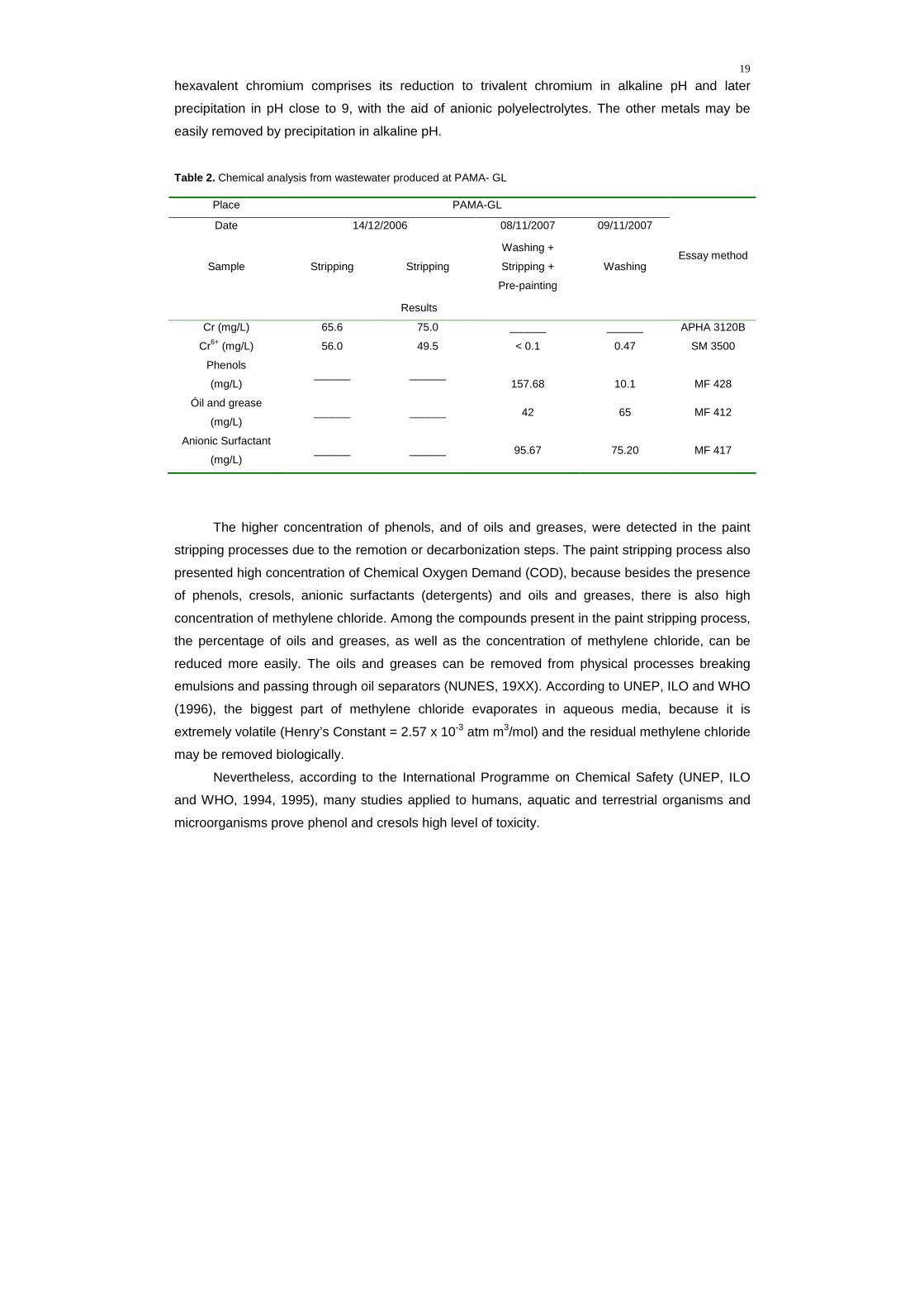
The higher concentration of phenols, and of oils and greases, were detected in the paint
stripping processes due to the remotion or decarbonization steps. The paint stripping process also
presented high concentration of Chemical Oxygen Demand (COD), because besides the presence
of phenols, cresols, anionic surfactants (detergents) and oils and greases, there is also high
concentration of methylene chloride. Among the compounds present in the paint stripping process,
the percentage of oils and greases, as well as the concentration of methylene chloride, can be
reduced more easily. The oils and greases can be removed from physical processes breaking
emulsions and passing through oil separators (NUNES, 19XX). According to UNEP, ILO and WHO
(1996), the biggest part of methylene chloride evaporates in aqueous media, because it is
extremely volatile (Henry’s Constant = 2.57 x 10⁻³ atm m3/mol) and the residual methylene chloride
may be removed biologically.
Nevertheless, according to the International Programme on Chemical Safety (UNEP, ILO
and WHO, 1994, 1995), many studies applied to humans, aquatic and terrestrial organisms and
microorganisms prove phenol and cresols high level of toxicity.

20
The need of removing these compounds demands the knowledge of their main physical-
chemical properties. According to BUDAVARI et al. (1989), phenol possesses white-colorless
crystal shape with boiling point at 43° C. It has an acr e smell and a pungent and spicy taste. When
in liquid state it presents transparent, colorless and low viscosity character. A phenolic solution
with approximately 10% of water is liquid at room temperature. Phenol is soluble in most organic
solvent (aromatic hydrocarbonates, alcohols, ketones, ethers, acids, and halogen
hydrocarbonates). However, it has its solubility limited whiled in aliphatic solvents.
Cresols are phenolic isomers with a methyl radical substituting the hydrogen in the orto,
meta or para in relation to the hydroxyl group. According to DEICHMANN and KEPLINGER
(1981), the commercial cresol, also known as cresilyc acid has the three isomers with low
quantities of phenols and xylenes. From the physical point of view, the cresols consist in a solid
white crystal or a yellowish liquid with pungent odor typical from phenols. Cresols are flammable
and soluble in water, ethanol, ether, ketone and alkaline hydroxides.
The phenol and cresols’ chemical properties are relatively close one to the other.
According to SOLOMONS (1996), the main characteristic of these compounds is the presence of
cyclic chains constituted by six atoms of carbon in hybridization type sp2. Therefore, the high
stability of the aromatic compounds would be related to the Bayer’s Tensions Theory. The
chemical reactions involve electrophilic substitution of the positions orto or para in relation to the
hydroxyl group. Cloration, bromation, sulphonation and nitrations are typical examples of these
reactions.
Phenol is sensitive to the action of oxidating agents. According to UNEP, ILO and WHO
(1994), the removal of the hydrogen atom from the hydroxyl group is followed by the resonance
and stabilization of the resultant phenoxy radical, which may be easily oxidized later. Depending
on the oxidating agent and the reaction conditions, products like dihydroxy, trihydroxy-benzenes
and quinones are formed. These properties make possible the use of phenol as an antioxidant,
acting like a radical capturer (trapping). Phenol also reacts with the carbonyls in acid or alkaline
media. In the presence of formaldehyde, phenol is easily converted into hydroxy-methyl-phenol
and latter converted into resins by condensation.
According to FIEGE and BAYER (1987), cresols can also go through condensation
reactions with aldehydes, ketones and dienes. The main physico-chemical characteristics of
phenol and cresols are presented in Table 3.

21
Table 3. Some physical and chemical properties of phenol and cresols (FIESER, 1930; VIDIC, SUIDAN and BRENNER, 1993; UNEP, ILO and WHO, 1994, 1995)
Organoleptic
Limits
in water (mg/L)
C
O
M
P
O
U
N
D
Molecular
Mass
(g/mol)
Critical
Oxidation
Potential
(V)
Relative
density
(25 ºC)
Melting
Point
(ºC)
Boiling
Point
(ºC)
Solubility
in water
at 25ºC
(g/L)
pKa
25 ºC Odour Taste
Phenol 94.11 1.089 1.07120ºC 43 181.75 93 9.89 7.9 0.3
o-cresol 1.040 1.135 30.94 191.0 25 10.20 1.4 0.003
m-cresol 1.080 1.030 12.22 202.32 26 10.01 0.8 0.002
p-cresol
108.14
1.038 1.154 34.74 201.94 23 10.17 0.2 0.002
Therefore, these effluents have pungent odor, unpleasant and high toxicity (LEMASTERS
et al., 1999), even when in low concentrations (Table 3). Considering the technical records of the
remover used by the Air Force Command (PENETONE CORPORATION, 2004), the mass rate of
the present aromatic compounds (phenol– 7.4%, 2-hydroxytoluene – 1.6%, 3-hydroxytoluene–
3.1%, 4- hydroxytoluene – 2.3% and xylenes – 0.4%), the toxicity and the physico-chemical
properties of these compounds (Table 3), the amount of chemical analysis already made (Tables
1 and 2) and the environmental discharge limit for phenols (BRASIL, 2005), it can be concluded
that phenol and cresols constitute the greatest challenge in the treatment of effluents in
aeronautical industry.
Thus it becomes necessary, to know the techniques normally used in the treatment of
these phenolic compounds.
1.2 Treatment Techniques to remove phenol and cresols
The techniques in the treatment of effluents which contain phenols may be divided in
biological, conventional physico-chemical and advanced oxidative processes (AOP’s).
1.2.1 Biological Processes
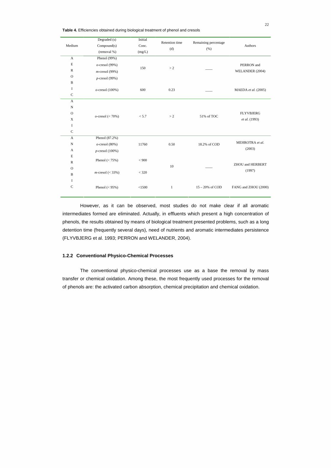
A great effort has been made to remove phenols by biological treatment. Table 4 presents
some published studies that made use of aerobic, anoxic and anaerobic processes.
22
Table 4. Efficiencies obtained during biological treatment of phenol and cresols
Medium
Degraded (s)
Compound(s)
(removal %)
Initial
Conc.
(mg/L)
Retention time
(d)
Remaining percentage
(%) Authors
Phenol (99%)
o-cresol (99%)
m-cresol (99%)
p-cresol (99%)
150 > 2 ____ PERRON and
WELANDER (2004)
A
E
R
O
B
I
C o-cresol (100%) 600 0.23 ____ MAEDA et al. (2005)
A
N
O
X
I
C
o-cresol (< 70%) < 5.7 > 2 51% of TOC FLYVBJERG
et al. (1993)
Phenol (87.2%)
o-cresol (80%)
p-cresol (100%)
11760 0.50 18.2% of COD MEHROTRA et al.
(2003)
Phenol (< 75%) < 900
m-cresol (< 33%) < 320
10 ____ ZHOU and HERBERT
(1997)
A
N
A
E
R
O
B
I
C
Phenol (< 95%) <1500 1 15 – 20% of COD FANG and ZHOU (2000)
However, as it can be observed, most studies do not make clear if all aromatic
intermediates formed are eliminated. Actually, in effluents which present a high concentration of
phenols, the results obtained by means of biological treatment presented problems, such as a long
detention time (frequently several days), need of nutrients and aromatic intermediates persistence
(FLYVBJERG et al. 1993; PERRON and WELANDER, 2004).
1.2.2 Conventional Physico-Chemical Processes
The conventional physico-chemical processes use as a base the removal by mass
transfer or chemical oxidation. Among these, the most frequently used processes for the removal
of phenols are: the activated carbon absorption, chemical precipitation and chemical oxidation.

23
1.2.2.1 Activated Carbon Absorption
Despite the fact that countless studies (CATURLA et al., 1988; JUANG et al., 1996) report
the removal of phenolic compounds from industrial effluents by means of activated carbon filters,
the available project parameters (DABROWSKI, 2005) are limited to the use in diluted solutions (<
20 mg/L).
Besides, some researchers state that there is no way to regenerate the filtering media in
the applications of activated carbon that contain elevated charges of phenols (GRANT and KING,
1990). Hence, the use of activated carbon to remove phenols is more recommended as a tertiary
process.
1.2.2.2 Chemical precipitation
According to RICHTER and AZEVEDO NETO (1991), chemical precipitation is frequently
applied in the removal of organic matter while in suspension or under colloidal shape, being
anteceded by coagulation and flocculation.
SOLOMONS (1996) states that phenols may be precipitated by means of bromation
reactions, forming precipitates as the 2, 4, 6-tribromophenol. Nevertheless, according to
KURAMOCHI et al. (2004), the solubility of this precipitate (59-61 mg/L in water at 25 ºC) exceeds
the environmental discharge limit for phenols, being necessary to make additional post-treatment
steps. Moreover, bromophenols present acute and chronic toxicity in seaweeds, protozoans and
fish (UNEP et al., 2005), even while under low concentrations (0.1 mg/L).
1.2.2.3 Conventional chemical oxidation
Chemical oxidation generally refers to the use of oxidizing agents aiming at destroying
toxic, refracting compounds or those which inhibit the growing of microorganisms
(ECKENFELDER, 2000). Considering the critical potential of phenol (1.089 V) oxidation (Table 3),
of the cresols (1.038 at 1.080 V) and the potential of conventional oxidation power, the ozone has
one of the higher reduction potentials (2.07 V, 25º C), being the most conventional oxidant used in
oxidating phenols.
Ozone stability in aqueous media is greatly influenced by factors such as pH, UV
irradiation, the presence of catalysts and ozone dosages. In acid media, in the absence of UV or
catalysts, high ozone dosages favor its action as a direct oxidant, that is, via molecular ozone. In

24
these cases, phenol (KUSIC et al., 2006), o- m- and p-cresol (ZHENG et al., 1993) oxidation rates
are respectively equal to 1300, 32240, 60870 and 45460 M-1 s-1.
Although, under these conditions, the ozone presents high selectivity towards the phenolic
compounds, the removal efficiency and the kinetic constants of ozone and other conventional
oxidants are too low while compared to ●OH produced in AOP’s.
1.2.3 Advanced Oxidative Processes (AOPs)
1.2.3.1 Conventional AOPs
The main principle of AOPs is the production of hydroxyl radical, ●OH, oxidizing agent with
high oxidation potential (2.80 V), what grants a lot of similarities to these processes. The high
potential of •OH justifies the efficacy of AOPs from the thermodynamic point of view.
Besides, the reaction rate constants between the ●OH and the organic pollutants are very
high (108 to 1010 M-1 s-1, ESPLUGAS et al., 2002), what guarantees the AOPs efficacy in what
concerns the kinetic point of view. The reactivity and instability of these radicals demand
processes able to assure in situ production. The reactions presented in Table 5 show how the ●OH
is generated by different processes.
The efficacy of these processes in phenol (ph) and cresols (o-cr, m-cr and p-cr) oxidation
may be confirmed from the destruction of these compounds forming other intermediates presented
in Table 6 and 7.
The rate constants of the reactions between hydroxyl radicals and phenol, o-, m-, p-cresols
(BUXTON et al., 1988; RODER et al., 1999) are respectively equal to 6.6 x 10⁹, 1.1 x 10¹⁰, 1.44 x
1010 and 1.2 x 10¹⁰ M-1s-1. These values assure AOP’s high efficiencies during phenol and cresols
degradation as it may be observed in all studies presented in Table 8.
Taking in consideration the absolute constants high rates of the reactions between phenols
and ●OH and that the hydroxyl concentration remains between 10-10 and 10-12 M, the organic
compounds degradation may be approximated to a pseudo first order kinetic constant with values
between 1 and 10-4 s-1.

25
Table 5. Reactions of production of •OH by AOP’s.
Reagents Main reactions (Equation) Source
O3 OH- 2O3 + OH- → O2•- + 2O2 + •OH (1)
O3 H2O2 O3 + H2O2 → •OH + HO2• + O2 (2)
GLAZE (1987)
H2O2 UV H2O2 + hν → 2 •OH (3) BELTRAN (2003)
O3 UV O3 + hν + H2O → H2O2 + O2 (4)
(2) KUSIC et al. (2006)
O3 H2O2 UV (2- 4)
H2O2 Fe2+
H2O2 + Fe2+ → FeOH2+ + •OH
H2O2 / R• + Fe3+ → HO2
• / R+ + FeOH2+/Fe2+
HO2• + Fe2+ → Fe3+ + HO2
-
(5)
(6)
(7)
NEYENS and BAYENS (2003)
H2O2 Fe2+ UV
FeOH2+ + hν → Fe2+ + •OH
Fe+3(RCO2)+2 + hν → Fe+2 + CO2 + R•
(8)
(9)
(5- 7)
PIGNATELLO (1992)
O3 Fe2+ O3 + Fe2+ + H2O → O2 + FeOH2+ + •OH (10)
O3 Fe2+ UV (2-4, 8, 10) SÁNCHEZ et al.
(2003)
UV TiO2
TiO2 + hν → h+ + e–
h+ + H2O (ads) → OH• + H+
O2 + e- → O2•-
O2•– + H+ → HO2
•
HO2• + HO2
• → H2O2 + O2
O2•– + HO2
• → HO2– + O2
HO2– + H+ → H2O2
H2O2 + e– → •OH + OH–
H2O2 + O2•– → •OH + OH– + O2
(11)
(12)
(13)
(14)
(15)
(16)
(17)
(18)
(19)
(3)
AL-EKABI et al (1989)
H2O 60Co g-rays 2H2O → H3O+ + •OH + e– (20)
H2O Ultrasound H2O → H• + •OH (21) BUXTON et al.
(1988)
H2O e- H2O → •OH + H+ + e- (22) COMINELLIS (1994)
O2 H2O e- ½ O2 + H2O → 2•OH (23) OTURAN (2000)
O2 H2O e- UV (8-9, 23) FLOX et al. (2007)

26
Table 6. Aromatic intermediates identified during phenol and cresols degradation by AOP’s.
Degraded compound AOP
Ph o-cr m-cr p-cr Intermediates Authors
Fenton (�) �●�� Catechol ZAZO et al. (2005)
Fenton (●) �●�� Hydroquinone BREMNER et al. (2006)
UV / H2O2 (�) �●�▼ 1, 4 –Benzoquinone TRYBA et al.(2006)
Photo-fenton (▲) �� Resorcynol ARAÑA et al. (2001)
� 1, 2, 4-benzenetriol O3 (�)
� � 3-methylcatechol HSU et al. (2007)
O3
O3 / H2O2
UV / H2O2
UV / O3
UV/O3/H2O2
(�) � 2-methylresorcynol KUSIC et al. (2006)
Anodic oxidation (▼) �� �� Methylhydroquinone TORRES et al. (2003)
Anodic oxidation (�) �� �� Methyl-p-benzoquinone LI et al. (2005)
Photo-electro-Fenton (�) � 5-methyl-2-hydroxi-p-
benzoquinone FLOX et al. (2007)
� 2-hydroxybenzaldehyde
� 3-hydroxybenzaldehyde
� 4-hydroxybenzaldehyde
� � 2,5-dihydroxybenzaldehyde
� 5-methyl-resorcynol
UV/TiO2 (�)
� � 4-methyl-catechol
WANG et al. (1998)
Table 7. Carboxylic acids identified during phenol and cresols degradation by AOP’s.
Degraded compound
AOP Ph o-cr m-cr p-cr
Intermediates Authors
Fenton (◦) ◦▷ Muconic ZAZO et al. (2005)
Fenton (●) ●▽◦▷ ◢ ◢ ◢ Maleic BREMNER et al. (2006)
Anodic oxidation (▽) ◦▷ ◢ ◢ ◢ Fumaric LI et al. (2005)
Photo-electro-Fenton (◢) ▽ Succinic FLOX et al. (2007)
Fenton (◣) ▽◦ Malonic KAVITHA and PALANIVELU(2005)
◢ ◢ ◢ Pyruvic
◢ ◢ ◢ Glycolic
◦ ◢◣ ◢◣ ◢◣ Acetic
▽◦▷ ◢◣ ◢◣ ◢◣ Oxalic
O3 (▷)
◦ ◢ ◢ ◢ Formic
HSU et al. (2007)

27
Table 8. Efficiencies obtained during phenol (Ph) and cresols (Cr) degradation by AOP’s.
[Conc]0 (mM)
AOP Ph Cr
t (h) Analysis Efficiency (%) Authors
O3 44
O3/Fe+3 52
O3/UV 56
O3/UV/Fe+3
1 DOC
90
CANTON et al.
(2003)
O3/H2O2 1.5 37
O3/UV 1 60
O3/H2O2/UV 2 45
H2O2/Fe2+ 1
Phenol
10
ESPLUGAS et
al. (2002)
O3 1.5 60-87
UV/TiO2
1.06
168 DOC
88-92 BESSA (2003)
UV/H2O2 1
Fenton 82
Photo-Fenton
2.12
_____
2 Phenols
99
KAVITHA and
PALANIVELU
(2004)
UV/TiO2 0.1 2.5 Cresols 98 88 93 WANG. et al.
(1998)
Fenton 1.85 2
Cresols DOC 82 42
KAVITHA and
PALANIVELU
(2005)
Anodic Oxidation (Ti/TiO2-RuO2-
IrO2/CF)
2.78 8 49.3 - 67.9
RAJKUMAR
and
PALANIVELU
(2003)
Anodic Oxidation (Pt/graphite)
5 20
Anodic Oxidation
(BDD/graphite)
0.66
4 100
FLOX et al. (2005)
4-6 dinitro-o-
cresol
Photo-electro-
Fenton(BDD/FC)
_____
1.12 2
DOC
87-90 FLOX et al.
(2007)
While observing Table 8, presented above, it can be verified that the higher efficiencies were
observed in AOPs combined at ultraviolet irradiation. However, despite some AOPs, like the
photo-catalysis of ozone (CANTON et al., 2003), the photo-Fenton process (KAVITHA and

28
PALANIVELU, 2004) and the photo-electro-Fenton process (FLOX et al. 2007) present high
degradation rates of phenol and cresols, the cost of chemical products or the turbidity
augmentation may limit the efficiency of these processes.
Since the last decade, electrochemistry offers a new technology of advanced oxidative
processes that allows reducing the parasite reactions and the restrictive operational parameters,
consequently increasing the efficiency of degradation and mineralization of organic compounds. In
electrochemical advanced oxidation processes (EAOP), ●OH may be produced by direct (BRILLAS
et al., 2005; FLOX et al., 2005), indirect (OTURAN, 2000; OTURAN et al. 2001) and coupled
oxidation (FOCKEDEY and VAN LIERDE, 2002; SIRÉS et al., 2007a).
1.2.3.2 Electrochemical Advanced Oxidation Processe s
1.2.3.2.1 Direct EAOP: Anodic Oxidation
In these processes, the ●OH is produced and transferred directly from the electrode
originated from the water oxidation in the anode, for this reason, it is frequently referred to as
anodic oxidation.
In anodic oxidation, GANDINI et al. (2000) state that ●OH are produced from the water
oxidation in different anodes (Pt, PbO2, SnO2, boron doped diamond, etc). However, according to
OTURAN and BRILLAS (2007), the most frequently used anodes in EAOP’s are platine and boron
doped diamond (BDD). According to FLOX et al. (2006), the anodic oxidation by BDD in acid
media may be represented in a simplified manner by Equation 24.
BDD(H2O) → BDD(•OH) + H+ + e- (24)
However, in all these processes, water is competitively oxidized by other mechanisms.
COMINELLIS (1994) proposes a generalized scheme that presents the typical oxidating processes
of water in anodes compound or coated by oxides layers. In the first stage, the water is oxidized in
its anodic surface (MOx) to produce adsorbed hydroxyl radicals, later oxidized according to
Equations (25) and (26).

29
MOx + H2O → MOx(•OH) + H+ + e- (25)
MOx(•OH) → MOx+1 + H+ + e- (26)
In the absence of any oxidizable agent, oxygen is produced from Equations (27) and (28).
MOx(•OH) → MOx + ½ O2 + H+ + e- (27)
MOx+1 → MOx + ½ O2 (28)
Therefore, adding the Equations (25) to (28), the equation of water degradation may be
obtained, under the absence of any oxidizable agent (29).
2H2O → 4H+ + O2 + 4e- (29)
On the other hand, in the presence of oxidizable organic compounds (R), the reactions
described in Equations (30) and (31) may occur:
R + MOx(•OH)n → CO2 + nH+ + ne- + MOx (30)

30
R + MOx+1 → MOx + RO (31)
TORRES et al. (2003) proposed a mechanism similar to the phenol anodic oxidation in
platine electrodes. In this mechanism, the oxidation mechanisms occur throughout the following
reactions presented in Equations (32 – 35).
Pt + H2O → Pt(•OH) + H+ + e- (32)
Pt(•OH) → PtO + H+ + e- (33)
RH + Pt(•OH) → Pt + mCO2 + H+ + e- (34)
RH + PtO → Pt + ROH (35)
Therefore, anodic oxidation functions as EAOP in Equations (24, 25, 30, 32 and 34). The
decisive factors to reduce the concurrent reaction of water oxidation to oxygen (Equation 29) are
related to the oxidizing power of the electrode (OTURAN and BRILLAS, 2007) and to the presence
of oxidizable substances according to Equation 34 (COMINELLIS, 1994; TORRES et al., 2003).
However, the anodic oxidation of high concentrations of phenol may lead to the formation of
polymers, as Figure 5 shows.

31
Figure 5. Reaction pathway during electrochemical phenol degradation. Experimental conditions: anodic oxidation in
indivisible cells with cathodes of stainless steel and anodes of Ti/SnO2-Sb, Ti/RuO2 or Pt (LI et al. 2005).
In the case of platine electrode, the transference of ●OH to the media is little according to its
low oxidating power (BRILLAS et al., 2007) because ●OH is strongly adsorbed to Pt surface. On
the other hand, BDD has one of the highest O2-overpotential, what justifies the fact that this
electrode presents the highest removal efficiency of organic compounds (GANDINI, 2000;
COMINNELLIS, 2001; BRILLAS et al., 2007). However, while applying more elevated electric
charges in the BDD anode, the relative generation of •OH by the Equation (20) is reduced

32
(PANIZZA and CERISOLA, 2005; FLOX et al., 2006) due to the increase in oxygen production
(Equation 29) and other weaker oxidants such as ozone (Equation 36), peroxydisulfate (Equation
37) and peroxide (Equation 38).
3H2O → O3 + 6H+ + 6e- (36)
2HSO4- → S2O8
2- + 2H+ + 2e- (37)
2H2O → H2O2 + 2H+ + 2e- (38)
Nevertheless the attack of the ●OH produced in the anodic oxidation only occurs in the
anodes surface, what limits the speed of the process (OTURAN and BRILLAS, 2007) in relation to
indirect EAOP’s.
1.2.3.2.2 Indirect EAOP: Electro-Fenton
The most used electrochemical advanced oxidation processes by indirect oxidation are the
electro-Fenton process and its variants (peroxi-coagulation) or combinations (coupling the anodic
oxidation and/or UV irradiation). The degradation of organic compounds (generically represented
as an organic compound R) by the electro-Fenton process is summed up as follows (Figure 6).
The electro-Fenton process, simultaneously developed in France (OTURAN et al., 1992)
and in Spain (BRILLAS et al., 1996), is based on the in situ electrochemical production of the
Fenton reagent, a mixture of hydrogen peroxide and iron ions (or other catalysts), capable of
producing hydroxyl radicals as shows Equation 5.
H2O2 + Fe2+ (Mn+) → FeOH2+ / (M(n+1)+) + •OH (5)
33
where:
Mn+ – Reduced form of M(n+1)/Mn+ redox catalyst couple; M(n+1)+ – Oxidized form of M(n+1)/Mn+ redox catalyst couple.
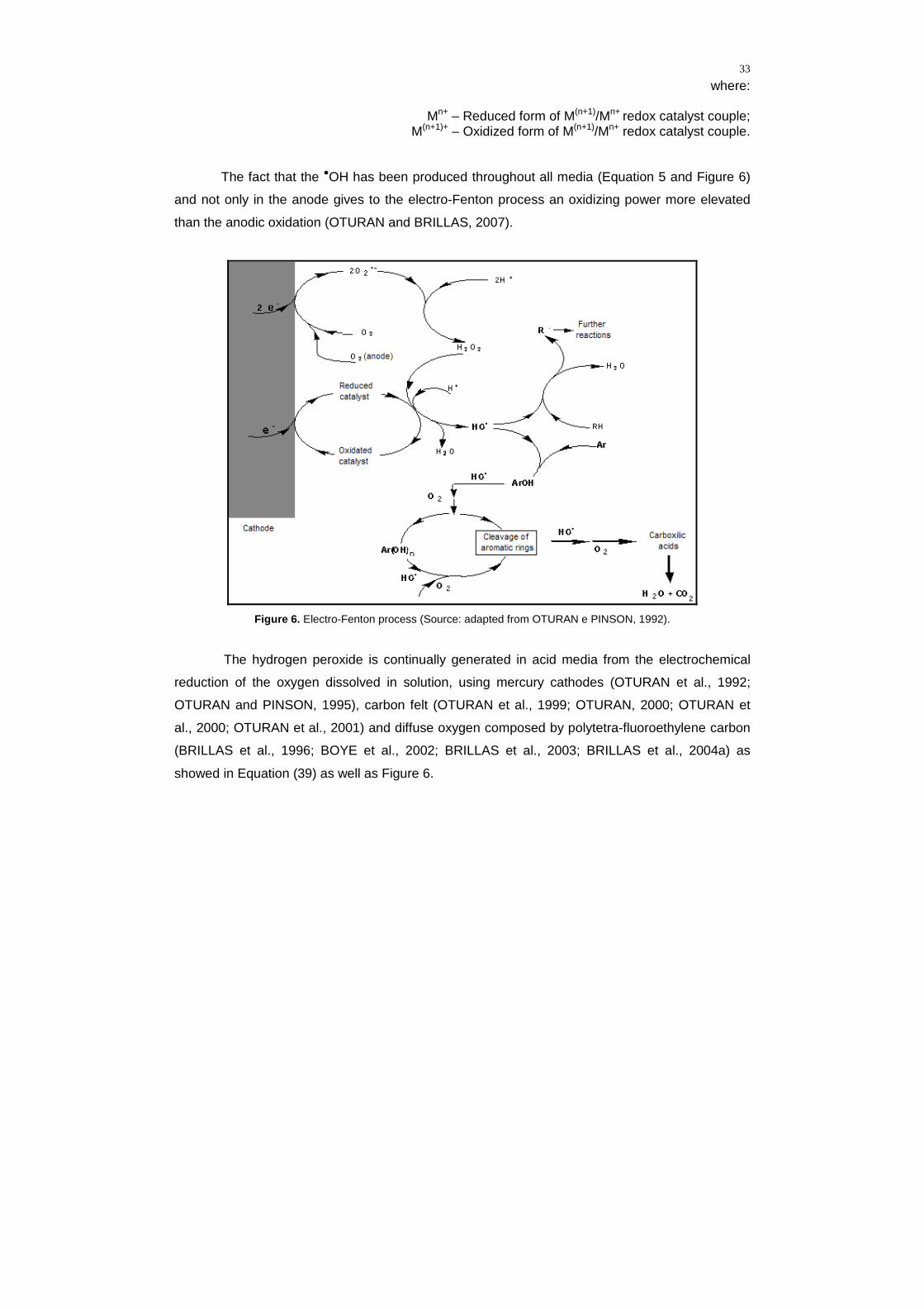
The fact that the ●OH has been produced throughout all media (Equation 5 and Figure 6)
and not only in the anode gives to the electro-Fenton process an oxidizing power more elevated
than the anodic oxidation (OTURAN and BRILLAS, 2007).
Figure 6. Electro-Fenton process (Source: adapted from OTURAN e PINSON, 1992).
The hydrogen peroxide is continually generated in acid media from the electrochemical
reduction of the oxygen dissolved in solution, using mercury cathodes (OTURAN et al., 1992;
OTURAN and PINSON, 1995), carbon felt (OTURAN et al., 1999; OTURAN, 2000; OTURAN et
al., 2000; OTURAN et al., 2001) and diffuse oxygen composed by polytetra-fluoroethylene carbon
(BRILLAS et al., 1996; BOYE et al., 2002; BRILLAS et al., 2003; BRILLAS et al., 2004a) as
showed in Equation (39) as well as Figure 6.

34
O2 + 2H+ + 2e- → H2O2 (39)
The addition of a small amount of Fe2+ or Fe3+ (or any transition metal that can act as a
catalyst) increases sensibly the oxidating power of the hydrogen peroxide produced
electrochemically, because it makes the production of •OH possible, from the Fenton’s reagent
represented by reaction (5). In the electro-Fenton process, the regeneration of the ferrous ion is
sensibly increased in relation to the Fenton’s reagent, because, beside the chemical regeneration
(reactions 6 and 7), the ferrous ion becomes regenerated electrochemically. In pH 3 (optimum
value for reaction 39), the electrochemical regeneration of the iron ion is represented by equation
40. The sum of equations (39) and (40) in acid media indicates the electrocatalytic production of
the Fenton’s Reagent (41).
Fe(OH)2+ + e- → Fe2+ + OH- (40)
O2 + 3H+ + Fe(OH)2+ + 3e- → H2O2 + Fe2+ + H2O (41)
Taking in consideration the reaction occurred on the cathode (reaction 41) and in the solution
(reaction 5), it can be observed that the concentration of dissolved oxygen is an essential factor in
the efficiency of electro-Fenton process.
Platine and BDD are the most used anodes in the electro-Fenton process (OTURAN et al.
2001; BRILLAS et al., 2007). Within these anodes, in the absence of any oxidizing agent
(COMINELLIS, 1994), an increment of the concentration of the dissolved oxygen in the media by
means of the following reaction occurs.
2H2O → 4H+ + O2 + 4e- (29)

35
Thus, while adding the reactions present on the cathode (41), on the anode (29) and in the
media (5) and keeping the electrical charge balanced, the electro-Fenton global reaction is
obtained:
O2 + 2H2O → 4•OH (42)
In the peroxi-coagulation, the principle is similar to the electro-Fenton process. The
difference resides in the use of a sacrificial iron anode, which allows its oxidation, producing mainly
the iron ion as equation 43 shows (BRILLAS et al., 1997).
Fe → Fe2+ + 2e- (43)
Hence, while adding the reactions present in the cathode (41), in the anode (43) and in
media (5), keeping the electrical charge balanced, the peroxi-coagulation global reaction is
obtained:
2O2 + 6H+ + 3Fe → 2•OH + 3Fe2+ + 2H2O (44)
Therefore, while comparing the electro-Fenton process (42) to the peroxi-coagulation (44) it
can be verified in this case, an excessive production or ferrous ion that ends up to be transformed
to the ferric ion with the pH increase and to act like a coagulant in the final products (BRILLAS and
CASADO, 2002).
OTURAN and BRILLAS (2007) claim that the substitution of the Pt anode by BDD allows
increasing considerably the efficiency of the electro-Fenton process, due to the supplementary •OH produced by equation (24). In this case, there is a combination of the electro-Fenton process
with the anodic oxidation (FOCKEDEY and VAN LIERDE, 2002).
Another possible combination comprises the use of the electro-Fenton process coupled to the
simultaneous radiation of ultraviolet light. This combination, also known as photo-electro-Fenton
process (BOYE et al., 2003; BRILLAS et al., 2003), allows accelerating the mineralization process
by:
a) Regeneration of the ferrous ion by the photo-reduction of ferric ions (reaction 8)
and/or;

36
b) Photo-decomposition of Fe3+ complexes with some products such as oxalic acid
(reaction 9).
Theoretically, the use of BDD anode in the photo-electro-Fenton process corresponds to the
combination of the electro-Fenton with higher oxidizing power (BRILLAS and OTURAN, 2007) and
has made possible to obtain high rates of mineralization during cresols oxidation. Figure 7
presents the photo-electrochemical degradation mechanism of the cresols isomers proposed by
FLOX et al. (2007) while making use of the photo-electro-Fenton process in a reactor containing
an oxygen diffusion cathode, a BDD anode and a UV-A lamp.
Figure 7. Proposed reaction sequence for the electro-Fenton and solar photoelectro-Fenton degradations of o-cresol, m-cresol and p-cresol in acid medium using a BDD anode. The hydroxyl radical is denoted as ●OH or BDD(●OH) when it is formed from Fenton’s reaction or at the BDD surface from water oxidation, respectively (FLOX et al., 2007).

37
Face so many present parameters in the electro-Fenton process, it becomes necessary to
perform a detailed analysis of the main influent parameters.
1.3 Influential parameters in the Electro-Fenton process
1.3.1 Electrode nature
According to OTURAN and BRILLAS (2007), Pt and BDD are the most used electrodes as
anodes. However, the cathode is the working electrode in the electro-Fenton process and currently
the carbon felt (CF) (HANNA et al., 2005; OTURAN and OTURAN, 2005; DIAGNE et al., 2007)
and the oxygen diffusion (OD)PTFE electrodes (BRILLAS et al., 2003; BRILLAS et al., 2004b) are
the most frequently used cathodes. Aiming to maximize the efficiency of the electro-Fenton
process about the electrodes used, SIRÉS et al. (2007b) have studied in detail the effect of the
electrodes Pt-CF, BDD-CF, Pt-OD and BDD-OD combination use in the electro-Fenton process
during the degradation of the antimicrobiotics tryclosan. Figure 8 presents the kinetic degradation
of Tryclosan under different combination of electrodes (Pt-CF, BDD-CF, Pt-OD and BDD-OD).
Figure 8. Triclosan degradation (V0 = 200 mL, C0 = 5 mg triclosan/L, pH = 3 e I = 60mA) in aqueous solution
containing 0.05M of Na2SO4 and 0.20 mM of Fe3+. Electrochemical cells: (●) Pt/FC, (∎) BDD/FC, (▲) Pt/O2
and (◆) BDD/O2 (SIRÉS et al., 2007b).
In this study, the tryclosan degradation rates followed the following order: Pt-CF > BDD-CF >
Pt-OD > BDD-OD. Therefore, the Pt anode and the carbon felt cathode (CF) presented the highest
efficiency. The higher efficiency of the Pt/CF cell was justified due to the fact that this system has

38
proportioned the highest capacity of regeneration of the ferrous ion. The biggest area of the carbon
felt cathode and the smaller oxidation power of the Pt anode made possible the presence of a
higher concentration of Fe2+, increasing the production of ●OH.
In another study, SIRÉS et al. (2007a) have studied the use of the same electrodes
combinations (Pt-CF, BDD-CF, Pt-OD and BDD-OD) during the degradation of 200 mL of aqueous
solution containing 84 mg/L of the chlorophene antimicrobials by electro-Fenton process. The
degradation rates obtained followed the order: Pt-CF > BDD-CF > BDD-OD > Pt-OD.
Consequently, the electrode combinations that allowed highest efficiency in the electro-
Fenton process were carbon felt cathode (CF) and platinum anode (Pt), followed by carbon felt
cathode (CF) and boron doped diamond (BDD) anode (SIRÉS et al., 2007a, 2007b).
1.3.2 pH
The pH is one of the main factors to be considered in the electro-Fenton process. According
to MIOMANDRE et al. (2005), the oxygen transfer is the limiting stage in the electrochemical
production process of hydrogen peroxide (equation 39). Taking in consideration the saturation of
oxygen dissolved in media ([O2] ≅ 0.25 mM), the reaction of oxygen consumption (39: [H+]/[O2] = 2)
and the electrocatalysis of the Fenton’s reagent (41: [H+]/[O2] = 3), it can be observed that the pH
3.0 ([H+]/[O2] ≅ 4) maximizes the efficiency of the process (PIMENTEL et al., 2008). Thus, the
acidity reduction (pH > 3), makes the peroxide production more difficult, as it can be observed in
Figure 9.
Figure 9. Change of accumulated H2O2 concentration with time during electrolysis of 50 mL of 0.1 M phosphate buffer solution in an undivided cell of Pt/graphite at: (a) pH=3.0, (b) pH=4.0 (CHEN et al., 2003).

39
On the other hand, the acidity increase (pH < 2.8), also disturbs the peroxide production,
because it enhances peroxide and sulphate complexes formation (OTURAN and BRILLAS, 2007).
Moreover, the pH has a specific effect depending on the catalyst adopted, what will be soon
exposed.
1.3.3 Nature and Catalyst Concentration
The classical electro-Fenton process is conducted with the reduced form of the redox system
Fe3+/Fe2+ (E0 = 0.77 V/SHE). Nonetheless, any proper redox system M(n+1)+/ Mn+ can be used
according to the equation (45). In these cases, the electro-Fenton efficiency is related to the
standard reduction potential and to the scavenging effect of the reduced species of the redox
system used (PIMENTEL et al., 2008).
Mn+ + H2O2 → M(n+1)+ + OH- + •OH (45)
In fact, some other transition metals have been tested as catalysts. Among these cobalt
(E0(Co3+/Co2+) = 1.92 V), cupper (E0(Cu2+/Cu+) = 0.16 V) and manganese (E0(Mn3+/Mn2+) = 1.50
V) have been the transition metals most frequently used (ANIPSITAKIS and DIONYSIOU, 2004;
BARRET and MCBRIDE, 2005; TÜRK and ÇIMEN, 2005; IRMAK et al., 2006; SKOUMAL, 2006).
All these redox pairs can be used, once the cathode interface potential in relation to the solution
(OTURAN and PINSON, 1995) is approximately equal to -0.25V (SHE).
FOCKEDEY and VAN LIERDE (2002) have studied the iron concentration effect in the
electrochemical degradation of phenol coupling the electro-Fenton process to the anodic
oxidization by means of a Sb-SnO2-Ti/ reticulated vitreous carbon cell, as Figure 10 shows.
It can be observed in Figure 10, that 50 mg/L of iron made possible the highest degradation
of phenol. The reduction of iron concentration revealed less efficiency in the process, because
there was no catalyst to produce OH radicals, as reaction 5 shows. On the other hand, the
increase in iron concentration reduced the efficiency by the presence of parasite reactions as
reaction 46.
Fe2+ + •OH → Fe3+ + OH- k = 4.3 x 10⁸ M-1 s-1 (46)

40
Figure 10. Evolution of COD (filled symbols) and phenol concentration (outlined symbols) vs. electrical charge for
coupled oxidation at various iron concentrations (∎: 5. ◆: 50 e ●: 200 mg/L). Operating conditions: 100 A/m2, 20 mg/L O2, and pH 3 (FOCKEDEY and VAN LIERDE, 2002).
1.3.4 Effect of the medium
DIAGNE et al. (2007) have recently studied the effect of the nature of the acid used to set the
pH in the mineralization of the methyl-parathion pesticide (MP) in the electro-Fenton process
(Pt/carbon felt) using Fe3+ as catalyst. The results obtained are presented in Figure 11.
Figure 11. Degradation kinetics of methyl parathion in several acidic media by electro-Fenton process: (◦): perchloric,
(△): sulfuric, (▫): hydrochloric, and (◇):nitric media. C0 = 0.13 mM, [Fe3+] = 0.1 mM, V = 0.150 L, I = 100 mA, DIAGNE et al. (2007).

41
The higher degradation was obtained in pH 3, for perchloride acid as for sulphuric acid,
confirming the expected results. The efficiency of the process was lower when the sulphuric acid
was used for all studied values of pH, probably due to the bigger amount of added acid, because
the sulphuric acid is a weaker one. Additionally, the sulphuric acid has a lower oxidation state,
making parasite reactions easier, such as reaction 47 (BUXTON et al., 1988).
OH• + HSO4- → SO4
•- + H2O k = 1.7 x 10⁶ L M-1 s-1 (47)
Considering the observed effect while making use of different acids, even when in low
concentrations (pH = 3, [acids] < 2mM), the influence of the electrolytes in the solution must be
taken in consideration, normally used in higher concentrations.
1.3.5 Electrolytes
DUTTA et al. (2001) have studied the effect of different electrolytes in the degradation of the
methylene blue coloring by the Fenton’s reagent as it can be observed in Figure 12.
Figure 12. Effect of eletrolytes on blue methylene degradation by Fenton process (DUTTA et al., 2001).
While observing Figure 12, it can be verified that sodium sulphate propitiates the highest
degradation efficiency in methylene blue, what can be justified by the highest rates observed in the

42
reaction between halogen ions and ●OH (BUXTON et al., 1988) according to Equations (48) and
(49).
•OH + Br - → BrOH- k = 1.1 x 10¹⁰ L M-1 s-1 (48)
•OH + Cl - → ClOH- k = 4.3 x 10⁹ L M-1 s-1 (49)
Considering the global reaction of the electro-Fenton process (42), the dissolved oxygen
concentration in the media and the current intensity used are essential parameters in the process.
1.3.6 Dissolved Oxygen concentration
FOCKEDEY and VAN LIERDE (2002) have studied the effect of dissolved oxygen
concentration (DO) in the electrochemical degradation of phenol, coupling the electro-Fenton
process to the anodic oxidation using a Sb-SnO2-Ti/ reticulated vitreous carbon cell. The
concentration of DO was altered including different emissions of pure oxygen, as it can be seen in
Figure 13.
Figure 13. Evolution of COD (filled symbols) and phenol concentration (outlined symbols) vs. electrical charge for
coupled oxidation at various dissolved oxygen concentration (∎: 4 mg/L, ▲: 10 mg/L, ●: 20 mg/L, and ◆: 27 mg/L). Operating conditions: 100A/m2, 50 mg/L Fe, and pH 3 (FOCKEDEY and VAN LIERDE, 2002).

43
While observing Figure 13, it can be verified that the optimum concentration of DO was equal
to 20mg/L. There was a small reduction in the phenol degradation efficiency when the DO
concentration was reduced from 20 to 10 mg/L. However, the reduction of the efficiency was
significant when the DO concentration was reduced to 4 mg/L. For the authors, the DO
concentration reduction favors competitive reactions in the cathode, reducing the peroxide
production (equation 39) over the hydrogen production (by the acidity reduction) and/or the organic
compounds reduction.
On the other hand, the increase in the DO concentration also reduced the process efficiency.
According to FOCKEDEY and VAN LIERDE (2002), in this case, the increment of very high
releases of pure oxygen reduced the hydrodynamic performance of the electrolytic cell
1.3.7 Current Density
The electrical current density corresponds to the ratio between the applied current and the
surface of the working electrode. Therefore, the current density can be altered by changing the
current and/or the surface of the working electrode. The electro-Fenton process is an
electrochemical process ruled by equation 42. So, the current increase maintaining a constant
working electrode area, allows improving the degradation rate by the increase of the ●OH
production rate, as Figure 14 shows.
Figure 14. Effect of current increase (▼: 60. ∎: 100. ●: 200 e ▲: 300 mA) on kinetics degradation of diuron herbicide in aqueous solution containing 0.05M Na2SO4 and 0.5mM Fe2+ in an indivisible Pt/CF cell. Experimental conditions: cathodic surphace equal to 60 cm2 and volume equal to 150 ml (EDELAHI et al., 2004).

44
Therefore, at first analysis, Figure 14 shows that the higher the current, the higher the
tendency to increase the degradation rate, what is naturally expected in an electrochemical
process.
However, in the electro-Fenton process, the dissolved oxygen, the water and the product to
be degraded (Figure 6) are consumed once the electrical current is applied. Thus, the
enhancement in the electrical productivity from the current increase has a limit that tends to be
defined by the dissolved oxygen concentration or by the concentration of the product to be
degraded in the media. This current is normally defined in relation to the working electrode area
and is known as limit current (ilim). The use of currents greater than limit current will promote the
increase of parasite reactions, which reduces the electrical productivity. Considering the use of
three-dimensional electrodes (FOCKEDEY and VAN LIERDE, 2002), the limit current (ilim) occurs
when the reaction becomes controlled by the mass transference process, being defined by the
Equation 50.
ilim = n x F x λ x Km x Cl (50)
where:
ilim – limit current (A); n – number of exchanged electrons;
F –Faraday’s constant (96485 C/mol); λ - ratio of the real area of the electrode to the projected area;
km – diffusion coefficient divided by the thickness of the boundary layer (m/s); Cl – Limit concentration (mol/m3).
Considering, for instance, phenol mineralization by ●OH during electro-Fenton process,
molecules may be simplified by reaction 51.
C6H5OH + 28 ●OH → 6CO2 + 17H2O (51)
Considering the electro-Fenton process general reaction (42) and the reaction (51), the
phenol degradation mechanism by the electro-Fenton process can be represented by equation 52.

45
C6H5OH + 7 O2 → 6CO2 + 3H2O (52)
Considering equation 52, the reaction rate in electro-Fenton process is limited by mass (O2 -
rapid or reversible system) or electronic (e- - slow or irreversible system) transfer. Hence, in the
electro-Fenton process, the increase of the cathode area increases the value of limit current to be
applied, improving the electrical productivity specially while making use of higher currents.
Additionally, the augmentation of cathodic surface in the electro-Fenton process improves the
contact between the working electrode and the focused chemical species (O2 and Fe2+, reaction
41), increasing the regeneration of the ferrous ion (QIANG, CHANG and WANG, 2003) and the
production of hydrogen peroxide (PIMENTEL et al., 2008).
1.3.8 Temperature
While studying the temperature effect on cresols destruction by Fenton’s reagent, KAVITHA
and PALANIVELU (2005) verified the increase in the apparent rate constants with the increase in
temperature, becoming stable at 30º C. Moreover, QIANG et al. (2003) revealed that the increase
in temperature improves the electrochemical regeneration of the ferrous ion.
On the other hand, the temperature increase reduces the concentration of dissolved oxygen
saturation in the media, limiting the efficiency of the electro-Fenton process globally. Therefore,
considering the dissolved oxygen in media concentration, equation 50 shows that the increase in
temperature causes the decrease in the density of limit current, reducing the electrical productivity
of the process.
1.3.9 Transport Phenomena
In all electrochemical process, mass transport, charge and heat transfer are closely related.
In the electro-Fenton process, the reaction of hydroxyl radicals production occurs in homogenous
medium according to the equation 5 and, both dissolved oxygen, as the catalyst, need to establish
contact with the cathode. Therefore, it is necessary to apply a mechanical potency (P) that
supplies a hydraulic gradient sufficiently high (G > 700 s-1) to promote an adequate agitation
degree (RICHTER and NETTO, 1991). The mechanical potency (P) in laboratory scale is
introduced by using magnetic stirrers and by the introduction of pure oxygen or compressed air in
media, according to the following equations.

46
P = µ x V x G2 (53)
where:
P – Mechanical potency applyed (W), µ – Absolute viscosity (kg m-1 s-1),
V – Volume (m3), G – Hydraulic gradient (s-1).
P = Pms + Pca (54)
where:
Pms – Mechanical potency due to magnetic stirrers (W),
Pca – Mechanical potency due to bubbles produced during air diffusion (W).
These potencies are respectively obtained by means of the Equations presented as follows.
Pms = vms x rH2O x g x Lms x n / 9.555 (55)
where:
Pms (W) – Potency supplyed by magnetic stirrer; vms –magnetic stirrer volume (m3); rH2O – water specific mass (kg/m3);
g –gravity aceleration (9.81 m/s2); Lam – magnetic stirrer length;
n – rotations par minute.
Pg = Qg x rH2O x g x hi (56)
where:
Pg (W) – Potency supplyed by gas injection;
Qg – Gas flow (m3/s);

47
hi – imersion profundity of gas diffusor.
As a result, the applied hydraulic gradient is obtained from Equations 54, 55 and 56, as
shown in Equation 57.
G = [g/(V x nH2O) x (0.10466 x vms x Lms x n + Qg x hi)]1/2 (57)
nH2O – Water dynamic viscosity (m2/s).

48
CHAPTER II: MATERIALS AND METHODES

49
2.1 Chemical Products
The names, uses, formulae and purities of the chemical substances are presented in Table 9.
Table 9. Name, use, formula and purity of chemical substances used in this work
Formula Formula Product Use
Purity (%) Product Use
Purity (%)
FeSO4.7H2O CH3OH Ferrous sulfate
heptahydrate 99 Methanol Eluent
99.7
CoSO4.5H2O C6H4(COOH)(OH) Cobalt(II) sulfate
pentahydrate 99 p-hydroxy-benzoic
Absolute
constants 99.5
CuSO4.5H2O Na2SO4 Cupper(II) sulfate
pentahydrate 99 Sodium sulfate
99
MnSO4.H2O KCl Manganese(II)
sulfate monoh.
Cat
ayst
98 Potassium cloride E
lect
rolit
e
99
C6H5OH C4H4O4 Phenol
99
Maleic (cis) and Fumaric
(trans) 99
C6H4CH3OH C4H6O4 o-cresol
98 Succinic
99
C6H4CH3OH C3H4O4 m-cresol
99 Malonic
99
C6H4CH3OH C3H4O3 p-cresol D
egra
ded
com
poun
ds
99 Pyruvic
98
C6H4(OH)2 C2H4O3 Catechol
99 Glycolic
99
C6H4(OH)2 C2H2O3 Hydroquinone
99 Glyoxylic monohidrate
98
C6H4O2 C2H2O4 Benzoquinone
99.5 Oxalic
98
C6H3CH3(OH)2 CH3COOH 3-methylcatechol
99
Acetic (also used as
eluent) 99.7
C6H3CH3(OH)2 CH2O2 2-methyl-
hydroquinone
Iden
tifie
d pr
oduc
ts
99 Formic
I
D
E
N
T
I
F
I
E
D
A
C
I
D
S
98
2.2. Solutions Prepared
Synthetic effluent solutions with variation volumes between 100 and 400 mL were
prepared with deionised water (conductivity < 6×10⁻⁸ S cm-1 at 25 °C), except for final experiments

50
conducted with real wastewater. Although phenols’ concentrations in effluents swing between 10
and 2300 mg/L (Table 1 and 2), in this work, phenol’s concentrations were between 31.3 and 419
mg/L (1 and 4 mM).
2.3. Analytical Techniques
Analytical techniques used are described above.
2.3.1 High performance liquid chromatography (HPLC)
Phenol, cresols and all other intermediates were identified by reversed phase liquid
chromatography, using a Merc-Hitachi high performance liquid chromatograph, Lachrom-Elite
model, controlled by an EZCHROM elite program. It was composed of a quaternary pump MH L-
7100, a diode array detector L-7455 and a Merck column L-7360 with thermostat.
The analyses were made by injecting 20 µL aliquots and the oven temperature was fixed at
40°C. The column, the wavelenght and the mobile phase were changed in the case of aromatic
compounds or carboxylic acids, according with the desired analyse.
Aromatic compounds were identified by a RP-C18 (5 mm, 250 mm x 4.6 mm) column coupled
with the diode array detector at 280 nm and a flow rate of 0.8 mL/min. Two different mixtures of
water/methanol/acetic acid were used as mobile phase at a flow rate of 0.8 mL/min during phenol
and cresol degradation (phenol: 79.2/19.8/1, v/v; cresols: 59.4/39.6/1 v/v).
Carboxylic acids were identified and measured by ion-exclusion chromatography fitted with a
Supelcogel H (250 mm x 4.6 mm) column at 40 °C. The detection was performed at 210 nm with a
mobile phase of 4 mM H2SO4 at a flow rate of 0.2 mL/min.
2.3.2 Total Organic Carbon (TOC)
Total Organic Carbon (TOC) amounts in aqueous solutions were obtained with a Shimadzu
VCSH carbon analyser. During all experiments, samples were collected and immediately
measured without using any filter.

51
2.4 Electrochemical Reactor
Experiments were performed at room temperature (25 ± 1 ºC) in an open undivided cylindrical
glass cell of diameter intern of 6 mm presented in Figure 15.
Figure 15. Electrochemical reactor used in electro-Fenton experiments.
Figure 15 presents an undivided cell with two electrodes totally immersed in the solution. The
cathode was a piece of carbon-felt (7 cm x 8 cm x 0,6 cm), placed on the inner wall of the cell.
Anode was a piece of Pt (1.5 cm x 2 cm) placed on the centre of the cell. Solutions were always
stirred magnetically in a a rate of 500 rpm. During experiments to study the effect of current
density, it was used a larger piece of carbon-felt (7 cm x 16 cm x 0,6 cm).
A control experiment was also conducted in 125 mL solution, using a cathode of a larger
surface (7 cm x 16 cm x 0.6 cm), in order to quantify external losses like phenol adsorption in
carbon-felt electrode.
Experiments were monitored by an EG&G Princeton Applied Research 273A
potentiostat/galvanostat that assured the application of different currents (60 ≤ I ≤ 500 mA).
e-
Pt anode
Carbon felt
(cátodo)
Stirring
Air
H2SO4 1 mM termometer
pHmeter
Galvostat (EG & G Princeton)
e-

52
Prior to the electrolysis, compressed air was bubbled through the solution for 15 minutes.
This proceeding was maintained during all experiments to garantee oxygen saturation in aqueous
media and to let the solution homogeneous.
A catalytic quantity of metal ion (catalyst) was added to solutions before starting the
electrolysis. Current remained constant during electrolysis and samples were withdrawn at
different coulometric charges.
The initial pH of solutions was adjusted in a range of 2.8 to 3.0 by the addition of
concentrated sulphuric acid (in experiments to identify intermediates) or hidrocloridric acid (in
experiments to measure TOC). In fact, pH remained almost constant, confirming the equations 40,
51 and 52. This pH range was chosen to optimize the hydrogen peroxide production in an acid
media saturated of dissolved oxygen ([O2] ≅ 0.25 mM, PIMENTEL et al., 2008), according to the
equation 37. The pH was measured by a pH glass electrode calibrated with standard buffers at pH
values of 4 and 7. Temperature changes were measured by a thermometer and were not
significant.
During synthetic experiments with higher electric currents (I / 200 mA), the ionic strength was
maintained constant by the addition of 50 mM of Na2SO4 (carboxilic acids evolution) or 75 mM of
KCl (mineralization experiments) to improve the conductivity of the medium. This procedure was
not necessary during experiments with real wastewater.
The experimental procedures are presented below.
2.5 Experimental Procedures
This work was developed at Laboratoire des Géomatériaux et Géologie de l’Ingénieur at
Université Paris-Est Marne la Vallée, in Noysy le Grand, in France. Each experiment was repeated
at least once a time. Data were presented only if the difference between results was above 5%
(five per cent). Experiments were made with the application of electrolysis in solutions with
different proportions of phenol, o- m- e p-cresol and some of their intermediates. Final experiments
were conducted with real effluent. The sequence of experiments was presented as follow.
2.5.1 Obtention of absolute rate constants
The competitive kinetics method (HANNA et al., 2005; DIAGNE et al., 2007) was used to
obtain phenol and o-cresol absolute constants at pH 3. These compounds were chosen because
they are the most persistent phenols present in the real effluent. This method considers that

53
hydroxyl radicals react mainly with the degradated compound (R) and with the reference substrate
(S). In this case, the degradation rate is presented by the equations 58 and 59.
-d[R]/dt = kR[•OH][R] = Kapp(R) [R] (58)
-d[S]/dt = kS[•OH][S] = Kapp(S) [S] (59)
where:
kapp – Apparent rate constant.
As the hydroxyl radicals are very reactive and present a very short life-time, it does not
accumulate in media and, consequently, they promote a pseudo first order kinetic behavior.
Therefore, as we divide the equation (58) by (59), integrating from the beginning of the experiment
(t0) to a generic time (t), it was obtained the equation 60:
ln([R]0/[R]t) = kR /kS × ln([S]0/[S]t) (60)
This method used equal initial concentrations of the compound and of the reference substract
(4-hydroxybenzoic acid — 4-HBA) and allowed obtaining the absolute constants of phenol and o-
cresol degradation by hydroxyl radicals at pH 3. These results aimed to confirm phenol as the
most resistant compound in relation to hydroxyl radicals attack at pH 3. The value used like
reference absolute constant (4-HBA) was equal to 1.63 x 10⁹ M-1 s-1 (BUXTON et al., 1988). The
others experiments intended to maximize the conditions to the compounds more persistent (s).
2.5.2 Influence of the catalyst nature
The effect of catalysts was compared by the observation of TOC removal measures
obtained through experiments made with four different catalysts (iron, cobalt, cupper, manganese).
Three experiments, for each catalyst, with three different concentrations were used to identify
optimal concentration range for each catalyst. These twelve experiments could be accelerated
increasing the current (I=100 mA) and decreasing phenol start concentration ([phenol]0 = 0.33 mM
with theoretical initial TOC0 = 24 mg/L). When the experiments ended, it was possible to compare
mineralization rates. The catalysts tested and their experimental concentrations are presented in
Table 10.

54
Table 10. Metal ions and salt concentrations used during catalyst’s experiments.
Catalysts
Salt used
Concentrations used (mM)
0.05
0.10
Co2+
CoSO4.5H2O
1.00
1.00
5.00
Cu2+
CuSO4.5H2O
10.00
0.05
0.10
Fe2+
FeSO4.5H2O
1.00
0.10
0.50
Mn2+
MnSO4.H2O
1.00
2.5.3 Effect of catalyst concentration and anodic o xidation
After obtaining the most efficient catalyst, kinetics experiments were conducted under
specific conditions (I = 60 mA and V0 = 125 mL) that allowed to identify the effect of catalyst
concentration during degradation of 1 mM of phenol and o-cresol. One additional experiment with
phenol electrochemical degradation without the presence of a catalyst, allowed to study the effect
of Pt anode in anodic oxidation. Two others additional experiments allowed to obtain apparent
constants of m- and p-cresol.
2.5.4 Identification of intermediates and oxidation reactions
When optimum conditions of the catalyst were obtained, some intermediates produced
during phenol and cresols degradation could be identified. Then, with the injection of samples
(volume = 20 µL) in High Performance Liquid Chromatograph (HPLC), phenol, o-, m-, p-cresol and
the intermediates were separated, identified according to reaction time and quantifed according to
obtained areas. The retention times of the identified compounds are presented as follow.

55
Table 11. Retention times obtained during compounds identification
Compound Retention time (min.) Compound Retention time (min)
Hydroquinone 4.20 Malonic acid 11.86
p-hydroxy-benzoic 5.00 o-cresol 12.20
2-methyl-hydroquinone 6.30 m-cresol 14.30
Benzoquinone 6.70 Succinic acid 14.30
3-methylcatechol 7.12 p-cresol 14.40
Oxalic acid 7.52 Glycolic acid 15.10
Catechol 7.60 Phenol 15.90
Maleic acid 9.20 Formic acid 16.02
Pyruvic acid 10.60 Fumaric acid 17.00
Glyoxylic monohidrate acid 11.40 Acetic acid 17.40
Additionally, to clarify the predominant degradation mechanisms, some intermediates were
degraded separetely.
2.5.5 Effect of current density and volume
The effect of the current density and treated volume were studied during experiments of
phenol and o-cresol degradation, keeping a constant current. The current density, in this case,
could be changed by the increase of the working electrode area (cathode). In this experiment, it
was used carbon-felt electrode with 112 cm2 (7 cm x 16 cm x 0.6 cm).
The effect of the current density has been also studied, increasing the current without any
variation in the area of the working electrode (cathode area = 56 cm2: 7 cm x 8 cm x 0.6 cm) in an
equimolar mixture of phenol and cresols.
2.5.6 Real wastewater treatment
After the experiments with synthetic samples of phenol, cresols and the identified
intermediates, a real wastewater sample (10 L) was collected during stripping process at Parque
de Material Aeronáutico do Galeão in november of 2007. This sample was immediately
transported by Brazilian Air Force to Université Paris-Est Marne-la-Vallée. Four electrochemical
experiments were made to optimize the efficiency of the electro-Fenton process, using electrolytic
cells containing carbon felt cathode and Pt or boron-doped diamond (BDD) anodes. These

56
experiments also studied the influence of chrome and other possible present metals in catalyst
efficiency of added iron.

57
CHAPTER III: ELECTRO-FENTON TREATMENT OF PHENOL, CRESOLS AQUEOUS SOLUTIONS AND REAL
“STRIPPING PROCESS” EFFLUENTS

58
The analysis of the results aimed to highlight the relationship between the phenomena
studied and other factors in each stage defined in the experimental procedures. With the exception
of the experiments with the real effluent, the other experiments were conducted with an undivided
cell that contain Pt as anode and carbon-felt as the cathode. During real effluent treatment, Pt
anode was replaced by boron-doped diamond (BDD) in three experiments.
3.1 Kinetics studies
Absolute rate constants of phenol and o-cresol degradation by hydroxyl radicals at pH 3
were obtained by the competitive kinetics method (HANNA et al., 2005; DIAGNE et al., 2007). The
concentrations of phenol (or o-cresol) and 4-hydroxybenzoic acid (4-HBA), used as standard
competition substrate, were equal to 0.5 mM. Experiments were conducted during thirty minutes
using 0.1 mM of ferrous ions as catalyst. The value used as hydroxybenzoic acid (4-HBA) absolute
constant was equal to 1.63 x 10⁹ M-1 s-1 (BUXTON et al., 1988) and allowed obtaining phenol and
o-cresol absolute constants.
Three experiments, including phenol and 4-hydroxybenzoic acid (4-HBA) oxidation by
electro-Fenton process, generated thirteen points that allowed obtaining a straight and fit line
(R2=0,999), as it is shown in Figure 16.
These thirtheen points (Figure 16) allowed obtaining the angular coefficients’s standard
deviation (s = 0.09). The application of distribution student’s t with a degree of freedom equal to 12
and a probability of 95% (t12, 0.95 = 1.78) produced the angular coefficients’s confidence interval
(IC0.95 = 0.013). The multiplication between the angular coefficient obtained (1.61 6 0.01) and 4-
HBA absolute constant (1.63 x 10⁹ M-1 s-1) showed that the value of phenol absolute constant in
pH 3 was equal to (2.62 6 0.02) x 109 M-1 s-1.

59
Figure 16. Determination of phenol absolute constant. Experimental conditions: V0 = 125 mL, I = 60 mA, [phenol]i ≅ [4HBA]i ≅ 0.5 mM, [Fe2+] = 0.1 mM, reaction time = 30 minutes and Pt (1.5 cm x 2 cm) / CF (7 cm x 8 cm x 0,6 cm) electrodes.
Similarly, two experiments including o-cresol and 4-hydroxybenzoic acid (4-HBA) oxidation
by hydroxyl radicals during electro-Fenton process, generated nine points that allowed obtaining a
straight and fit line (R2=0,999), as it is shown in Figure 17.
Figure 17. Determination of o-cresol absolute constant. Experimental conditions: V0 = 125 mL, I = 60 mA, [phenol]i ≅ [4HBA]i ≅ 0.5 mM, [Fe2+] = 0.1 mM, reaction time = 30 minutes and Pt (1.5 cm x 2 cm) / CF (7 cm x 8 cm x 0,6 cm) electrodes.
These nine points (Figure 17) allowed obtaining the angular coefficients’s standard
deviation (s = 0.19). The application of distribution student’s t with a degree of freedom equal to 8
y = 1.608x
R2 = 0.999
0
0.2
0.4
0.6
0.8
1
1.2
1.4
0 0.2 0.4 0.6 0.8
Ln ([4HBA] i/[4HBA] t)
Ln ([P
heno
l] i/[
Phe
nol]
t)
kphenol
k4HBA
y = 2.27x
R2 = 0.999
0
0.5
1
1.5
2
2.5
3
3.5
4
0 0.5 1 1.5 2
Ln(4HBA 0/4HBA t)
Ln(o
-cre
sol 0
/o-c
reso
l t)
ko-cresol
k4HBA

60
and a probability of 95% (t8, 0.95 = 1.86) produced the angular coefficients’s confidence interval
(IC0.95 = 0.12). The multiplication between the angular coefficient obtained (2.27 6 0.12) and 4-HBA
absolute constant (1.63 x 10⁹ M-1 s-1) showed that the value of o-cresol absolute constant in pH 3
was equal to (3.70 6 0.19) x 109 M-1 s-1.
High values of correlation coefficient (R2) obtained in Figures 16 and 17 evidenced the
pseudo first order kinetic, typical of AOP’s. The absolute rate constants obtained were close, but
phenol was more persistant than o-cresol. Additionally, phenol concentration is usually four times
higher o-cresol concentration in commercial paint strippers (PENETONE CORPORATION, 2004),
therefore, most experiments aimed to optimize the removal of phenol and its intermediates.
3.2 Influence of the catalyst nature
From the experiments using Co2+ (E0(Co3+/Co2+) = 1.92 V), Cu2+ (E0(Cu2+/Cu+) = 0.16 V),
Fe2+ (E0(Fe3+/Fe2+) = 0.77 V) and Mn2+ (E0(Mn3+/Mn2+) = 1.50 V) ions, it was possible to study the
influence of the catalyst in phenol mineralization, as shows Figure 18. In these experiments (V0 =
330 mL, I = 100 mA, pH = 3, with theoretical TOC0 = 24 mg/L), different behaviours could be
observed to iron and cobalt experiments in relation to cupper and manganese. TOC removal rates
from the experiments including iron and cobalt are really different when compared with copper and
manganese (Figure 18). Higher rates (about 80% and 78% for iron and cobalt respectively in 4 h of
electrolysis) were obtain when 0.1 mM of iron(II) or cobalt(II) ions was employed as catalyst.
Stronger changes in color were also observed, which can be explained by the formation of
quinones (AZEVEDO, 2003; MACIEL et al., 2004). In these cases, catalyst concentrations greater
than 0.1 mM harmed the efficiency of the treatment, which can be explained by scavenging
reactions between iron(II) and / or cobalt(II) ions and hydroxyl radicals (Equations 46 and 61).
Fe2+ + •OH → FeOH2+ k = 4.3 x 10⁸ M-1 s-1 (46)
Co2+ + •OH → CoOH2+ k = 8 x 10⁵ M-1 s-1 (61)

61
Figure 18. TOC removal with electrolysis time for the mineralization of 0.33 mM (TOC0 = 24 mg L-1) phenol aqueous
solution with different catalysts during electro-Fenton treatment: [Fe2+]: 0.05 mM (-□-), 0.10 mM (-�-),
1.00 mM (-∆-); [Co2+]: 0.05 mM(-▲-), 0.10 mM (--), 1.00 mM (-♦-); [Mn2+]: 0.10 mM (---), 0.50 mM (◊),
1.0 mM (-�-); [Cu2+]: 1.0 mM (-+-), 5 mM (-�-),10 mM (-X-). Experimental conditions: Initial volume (V0) = 330 mL, I = 100 mA, pH = 3 and Pt (1.5 cm x 2 cm) / CF (7 cm x 8 cm x 0.6 cm) electrodes.
When copper or manganese is used as catalyst, optimum catalyst concentration is higher (5
mM for Cu2+ and 1 mM for Mn2+) in comparison with the optimal concentrations of Fe2+ and Co2+.
In fact, the reduction in catalyst concentration decreased considerably the efficiency in relation to
iron and cobalt (about 35% to 1 mM of Cu2+ and 0.1 mM of Mn2+). Although mineralization rates
were optimized to 5 mM of Cu2+ and 1 mM of Mn2+, they remained lowers in comparison to the
rates obtained from the experiments with cobalt and iron. Loss of eficiency can be justified by
metallic deposition on electrodes, observed in both cases. It evidenced reduction in catalyst
concentration and, consequently, decrease of hydroxyl radical production (Equation 45).
Cupper deposition on carbon-felt cathode can be justified by the high values of standard
reduction potentials to Cu(II) (E0Cu2+/Cu(s) = 0.34 V/SHE) and Cu(I) (E0Cu+/Cu(s) = 0.52 V/SHE)
ions.
During experiments with manganese, it was observed a reddish oxide deposition on Pt
anode. This phenomena is frequent in electrochemical experiments conducted with Pt in acid
0.20
0.60
1.00
0.00 1.00 2.00 3.00 4.00
Tempo (h)
COTt COT0

62
media and can be justified by the chemical reaction presented in Equation 58 (GHAEMI et al.,
2001; WU and CHIANG, 2006).
Mn2++ 2H2O → MnO2 (s) + 4H+ + 2e- (62)
In the other hand, cathode potential (≅ -0.25 V/SHE, OTURAN and PINSON, 1995) did not
favor iron (E0Fe2+/Fe(s) = -0.44 V, E0
Fe3+/Fe(s) = -0.04 V) neither cobalt (E0Co2+/Co(s) = -0.28 V)
deposition, optimizing catalyst action of these ions. Considering that iron presented a higher
eficiency and that cobalt is more toxic for the environment, iron was selected for the other
experiments.
3.3 Effect of catalyst concentration and anodic oxidation
Kinetic experiments were carried out in aqueous solutions containing 1.05 mM of phenol or o-
cresol in the presence of Fe(II) ions to study the effect of the catalyst concentration. They were
conducted with Fe2+ ions because Fe2+ presented better results as catalyst during phenol
mineralization at previous experiments.
Figure 19 shows kinetic curves in function of electrolysis time with Iron (II) concentrations
from 0.05 to 1.00 mM. The insert of Figure 19 (Ln([fenol]0/[fenol]t) in function of time) allowed
obtainin all apparent rate constants during phenol degradation. In this case, an additional and fast
experiment (duration of fifteen minutes) was conducted in the lack of iron (II), obtaining phenol
aparent rate constant during anodic oxidation.

63
Figure 19. Effect of catalyst (Fe2+) concentration on the degradation kinetics of phenol at pH 3 during current
controlled electrolysis by electro-Fenton process at 60 mA: (-△-): [Fe2+] = 0 mM (R2=0.997); (-□-): [Fe2+] =
0.05 mM (R2=0.997), (-■-); [Fe2+] = 0.1 mM (R2=0.998); (-●-): [Fe2+] = 0.25 mM (R2=0.999); (-▲-): [Fe2+] = 0.5 mM (R2=0.998); (-�-): [Fe2+] = 1.0 mM, (R2=0.997). Experimental conditions: V0=125 mL and Pt (1.5 cm x 2 cm) / CF (7 cm x 8 cm x 0,6 cm) electrodes.
In experiments with Fe2+ concentrations higher than 0.1 mM, it was observed an increase in
degradation rates with the reduction of iron concentration (kapp 1mM = 0.01560.005 < Kapp 0.5mM =
0.02460.005 < kapp 0.25mM = 0.02860.001 < kapp 0.10mM = = 0.03760.003 min-1). Probably, in
these conditions, the reduction of iron concentration decreased parasite reactions, consuming
hydroxyl radicals particularly due to the equation (46).
On the other hand, in experiments with iron concentrations lower than 0.1 mM, the reduction
of iron concentration decreased the degradation rates (Kapp 0.10mM = 0.03760.003 < < kapp 0.05mM =
0.02560.003 < Kapp 0mM = 0.00260.001 min-1). In these conditions, iron concentration was
insufficient to catalyze the electro-Fenton system efficiently according to equation (5). The great
difference between apparent constants obtained through experiments with 0 and 0.1 mM of iron
evidenced that the production of hydroxyl radicals in Pt electrode (anodic oxidation) was
despicable.
These results underline once again that under our experimental conditions a concentration of
0.1 mM ferrous iron constitute the optimal value for an effective oxidation of phenol in aqueous
medium. Under these conditions, the complete degradation of a concentrated phenol solution
0.00
1.00
0 25 50 75 100 125
time (min)
[Phe
nol]
(mM
)
0
0.2
0.4
0.6
0.8
1
0 10 20 30
time (min)
Ln (C
0/C
t)

64
(1.05 mM) took place in less than 100 minutes, even when the applied current was relatively small
(60 mA).
The effect of iron concentration in kinetic degradation of o-cresol has also been studied as
presented in Figure 20. In optimum conditions, the apparent rate constants of m- and p-cresol
were determined.
Figure 20. Effect of catalyst (Fe2+) concentration on the degradation kinetics of o-cresol: (-□-) [Fe2+] = 0.05 (R2=0.997),
(-■-) [Fe2+] = 0.10 (R2=0.999), (-▲-) [Fe2+] = 0.25 (R2=0.997) and (-△-) [Fe2+] = 1 mM (R2=0.996); m-cresol: (-○-) [Fe2+] =0.10 mM (R2=0.999) and p-cresol: (-●-) [Fe2+] = 0.10 mM (R2=0.998) at pH 3 during current controlled electrolysis at 60 mA by electro-Fenton process. Experimental conditions: V0=125 mL and Pt (1.5 cm x 2 cm) / CF (7 cm x 8 cm x 0,6 cm) electrodes.
During kinetic experiments involving o-cresol degradation, catalyst optimum concentration
obtained was also equal to 0.1 mM of Fe2+. In these conditions, the apparent constants obtained
during the degradation of 1.05 mM m-cresol (kapp 0.1mM = 0.03260.001 min-1) and 1.05 mM p-cresol
(kapp 0.1mM = 0.02460.001 min-1) fortified the major persistence of o-cresol (kapp 0.1mM = 0.00960.001 min-1)
between the cresols (BUXTON et al., 1988; RODER et al., 1999). Probably, the presence of a
greater number of orto and para-positions relatives to hydroxyl radical can justify greater
degradation rates obtained with m-cresol.
However, apparent constants obtained during o-cresol degradation (kapp 0.1mM = =
0.00960.001 > kapp 0.25mM = 0.00860.001 > kapp 0.05mM = 0.00760.001 > kapp 1.00mM = 0.00660.001 min-1) were
lower in relation to phenol constant (kapp 0.10mM = 0.03760.003 min-1). In fact, under optimal conditions,
the complete degradation of a concentrated solution of o-cresol (1.05 mM) occurred in less than
300 minutes, about the triple time necessary to phenol degradation (Figure 19). The additional
0.0
1.0
0 50 100 150 200 250 300 350
time (min)
[o-c
reso
l] (m
M)
0.0
0.2
0.4
0 10 20 30 40
time (min)
Ln(C
0/C
t)

65
methyl radical present in o-cresol may have produced a greater number of intermediates that
competed by hydroxyl radicals and harmed o-cresol degradation.
Additional experiments were performed to identify main intermediates formed during phenol
and cresols degradation in order to highlight degradation mechanisms.
3.4 Identification of intermediates
During electro-Fenton treatment, the oxidation reactions produced intermediates, identified in
two stages: identification of aromatics and carboxylics acids. The first one included identification of
aromatic intermediates during oxidation of compounds more persistents. It was possible to identify
three intermediates for phenol and two for o-cresol, but it was not possible to identify aromatic
compounds in experiments realized to obtain apparent constants of m- and p-cresol. In fact, the
aromatic intermediates were identified through previous experiments realized to verify the effect of
iron concentration in phenol and o-cresol degradation.
In the other hand, in second stage, the main carboxylic acids formed during phenol and
cresols degradation were identified in separate experiments. Experimental conditions were
modified increasing applied current (I = 60 → 200 mA) and initial concentration of the substance to
be degraded (C0 = 1.05 → 2.50 mM), because carboxylic acids appear as final and more
persistant oxidation products of the process.
As follows, the main aromatic compounds produced and destroyed in phenol and o-cresol
electrochemical degradation are presented.
3.4.1 Evolution of aromatic intermediates
During phenol oxidation by electro-Fenton process, main reactions were successively
electrophilic addition of hydroxyl radical on the aromatic ring leading to the formation of
polyhydroxylated benzene derivatives, such as hydroquinone and catechol which were oxidized to
quinine groups such as p-benzoquinone. The evolution of these substances in aqueous medium is
represented in Figure 21.

66
0
0.1
0.2
0.3
0.4
0 50 100 150
time (minutes)C
once
ntra
tion
(mM
)
Figure 21. Time-course of aromatic intermediates: (-■-) p-benzoquinone; (-□-) catechol and (-▲-) hydroquinone during the degradation of 1.05 mM phenol aqueous solution by electro-Fenton process. Experimental conditions: [Fe2+] = 0.10 mM, V0 = 125 mL, pH = 3 and I = 60 mA and Pt (1.5 cm x 2 cm) / CF (7 cm x 8 cm x 0,6 cm) electrodes.
These results corroborate previous studies presented in Table 6. The sum of intermediates
maximum concentrations obtained shows that these substances corresponded to the predominant
process of phenol degradation (about 70%), being completely degraded in about 150 minutes. The
reaction mechanisms that lead to the production of these intermediates are presented in Figure 22
(reactions 63-65).
The orto and para inductive effect in relation to –OH group (CHANG, 2003) conducted
hydroxyls radicals attack, producing catechol and hydroquinone as mainly directed products in
phenol oxidation, according to reaction 63. Simultaneously, it can occur hydrogen atom
abstraction reactions (reaction 65), but, degradation reaction constants are smaller in comparation
to electrophilic addition reactions (BUXTON et al., 1988). The higher oxidative potential of the
medium allowed the oxidation of hydroquinone to p-benzoquinone according to reaction 64. The
small hydroquinone accumulation in the medium can be explained by its quick transformation to p-
benzoquinone and in parallel by its hydroxylation or mineralization reactions. In fact, p-
benzoquinone (k1,4 BQ = 1.2 x 10⁹ M-1 s-1, ADAMS and MICHAEL, 1967) and hydroquinone (kHQ =
1.0 x 10¹⁰ M-1 s-1, HECKEL and HEINGLEIN, 1966) absolute rate constants of degradation by
hydroxyl radicals show that hydroquinone has a greater tendency to be oxidized.

67
(63)
(64)
(65)
Figure 22. Proposed reaction mechanisms for hydroxyl addition and hydrogen atom abstraction during phenol oxidation by ●OH radicals.
Figure 23 shows the main aromatic compounds produced and oxidized in o-cresol
electrochemical degradation. During o-cresol electrolysis, the main initial reactions were
successively electrophilic additions of hydroxyl radical on the aromatic ring, leading to the
formation of 3-methylcatechol and methyl-hydroquinone. This fact is in agreement with the studies
presented in Table 6. The mechanisms of the reactions that lead to the production of these
intermediates are presented in Figure 24 (reactions 66 and 67).

68
Figure 23. Time-course of aromatic intermediates: (-■-) 3-methyl-catechol and (-▲-) methyl-hydroquinone during the degradation of 1.05 mM o-chresol aqueous solution by electro-Fenton process. Experimental conditions: [Fe2+] = 0.10 mM, V0 = 125 mL, pH = 3 and I = 60 mA and Pt (1.5 cm x 2 cm) / CF (7 cm x 8 cm x 0,6 cm) electrodes.
(66)
(67)
Figure 24. Proposed reactions mechanisms of hydroxyl addition on o-chresol aromatic ring by electro-Fenton process.
The orto and para inductive effect in relation to –OH group (CHANG, 2003), like in phenol’s
oxidation, directed the hydroxyls attacks according to reactions 66 and 67. The sum of the
maximum concentrations obtained (Figure 23) shows that these intermediates represented a
higher percentual (58%) of o-cresol degrading process (1,05 mM) and that they were completely
degraded in about 300 minutes

69
As follows, it was possible to present main carboxylic acids produced and oxidized during
phenol and cresols electrochemical degradation.
3.4.2. Evolution of carboxilic acids
3.4.2.1. Identified carboxylic acids in phenol oxid ation
Phenol’s oxidation formed polyhydroxylated derivative and/or quinones. As follows, aromatic
ring opening reactions leaded to the formation of carboxylic acids. Figure 25 presents the evolution
of the identified carboxylic acids formed during phenol oxidation.
Figure 25. Evolution of carboxylic acids identified during oxidation of phenol by electro-Fenton treatment: maleic (-■-),
fumaric (-□-), succinic (-△-), glyoxylic (-○-), formic (-●-) and oxalic (-◇-) acids. Experimental conditions: [Phenol]0 = 2.50 mM, [Fe2+] = 0.10 mM, [Na2SO4] = 50 mM, V0 = 125 mL, I = 200 mA, pH= 3.0 and Pt (1.5 cm x 2 cm) / CF (7 cm x 8 cm x 0,6 cm) electrodes.
Maleic, glyoxylic succinic and fumaric acids were the predominant carboxylic acids formed in
the earlier stages of the treatment. Maleic acid reached its maximum concentration at 15 min,
being subsequently quickly degraded in about 150 minutes.
Glyoxylic and succinic acids started to be formed in the first minutes and both reached
maximum concentrations at 120 minutes. The curves show that the disappearance of glyoxylic and
succinic acids was followed by the appearance of formic and oxalic acids as end products, before
total mineralization. The transformation of glyoxylic acid into oxalic acid by electrochemical

70
advanced oxidation methods was already reported by BOYE et al. (2002). Traces of malonic,
pyruvic and acetic acids were also detected.
In order to clarify the formation mechanism of carboxylic acids, additional oxidation
experiments with the most important aromatic intermediates (benzoquinone, hydroquinone and
catechol) were carried out at the same experimental conditions during one hour. These results are
represented in Figures 26 (a), (b) and (c).
Figure 26 shows the identified acids formed during the oxidation of the main intermediates by
hydroxyl radicals. Polyhydroxylated benzenic compounds formed are very unstable which hinders
their identification. So, in order to simplify the reaction mechanism, we proposed complete
reactions presenting ring opening reactions directly from dihydroxylated derivatives.
During benzoquinone (Figure 26 (a)) and hydroquinone (Figure 26 (b)) oxidation with
hydroxyl radicals, glyoxylic and fumaric acids were predominantly formed. Traces of malonic,
pyruvic, oxalic (Figures 26 (a) and (b)) and maleic (26 (b)) acids were also detected. Therefore, It
could be verified that the same carboxylic acids were essentially formed, confirming of
hydroquinone to benzoquinone (reaction 64). Besides, only in these experiments, pyruvic acid
could be detected in the earlier minutes. Then, it was proposed that glyoxylic, fumaric and pyruvic
acids were directly formed from hydroquinone/benzoquinone destruction.
(a)
0.0
0.4
0.8
1.2
1.6
2.0
0 20 40 60
time (min)
Con
cent
ratio
n (m
M)
0
0.03
0.06
0 20 40 60time (min)
Con
c. (
mM
)
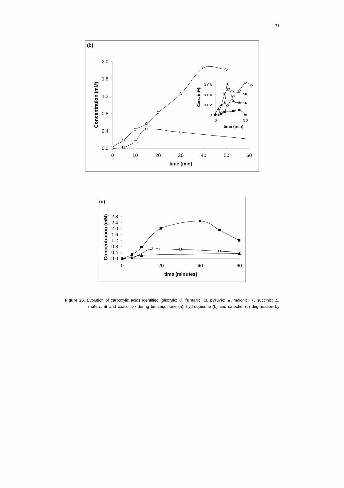
71
(c)
0.00.40.81.21.62.02.42.8
0 20 40 60
time (minutes)
Con
cent
ratio
n (m
M)
Figure 26. Evolution of carboxylic acids identified (glioxylic: ○, fumaric: □, pyruvic: ▲, malonic: ∗, succinic: △,
maleic: ■ and oxalic: ◇) during benzoquinone (a), hydroquinone (b) and catechol (c) degradation by
(b)
0.0
0.4
0.8
1.2
1.6
2.0
0 10 20 30 40 50 60
time (min)
Con
cent
ratio
n (m
M)
0
0.02
0.04
0.06
0 50
time (min)
Con
c. (m
M)
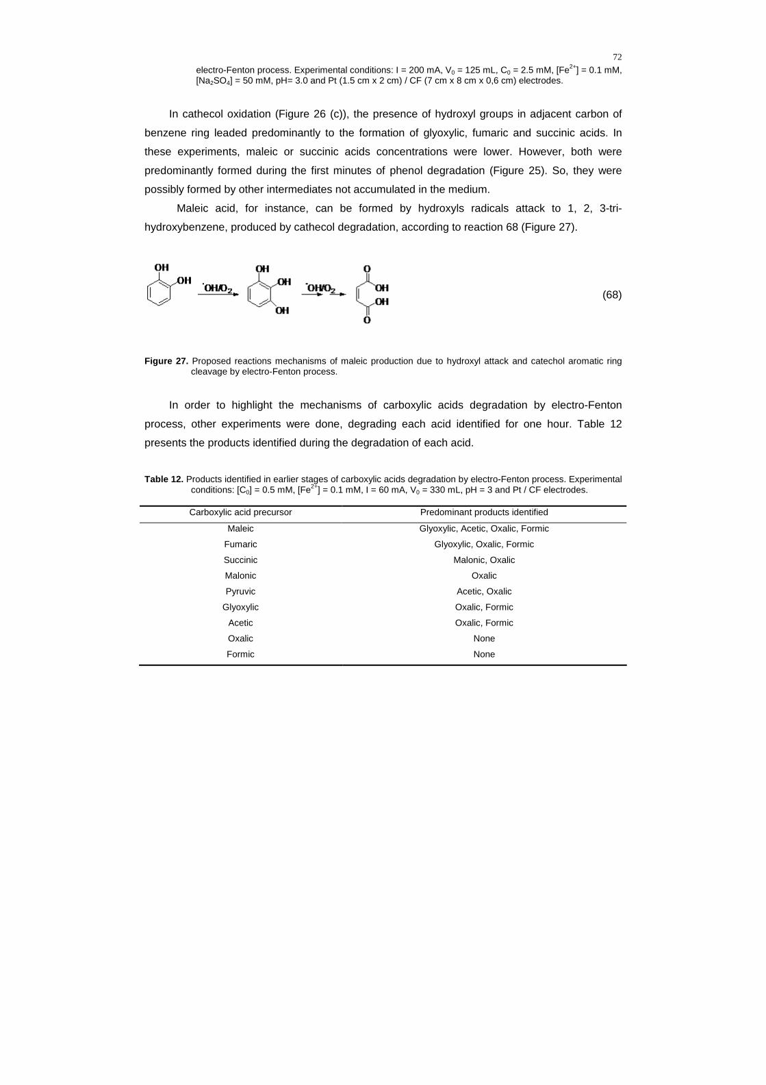
72
electro-Fenton process. Experimental conditions: I = 200 mA, V0 = 125 mL, C0 = 2.5 mM, [Fe2+] = 0.1 mM, [Na2SO4] = 50 mM, pH= 3.0 and Pt (1.5 cm x 2 cm) / CF (7 cm x 8 cm x 0,6 cm) electrodes.
In cathecol oxidation (Figure 26 (c)), the presence of hydroxyl groups in adjacent carbon of
benzene ring leaded predominantly to the formation of glyoxylic, fumaric and succinic acids. In
these experiments, maleic or succinic acids concentrations were lower. However, both were
predominantly formed during the first minutes of phenol degradation (Figure 25). So, they were
possibly formed by other intermediates not accumulated in the medium.
Maleic acid, for instance, can be formed by hydroxyls radicals attack to 1, 2, 3-tri-
hydroxybenzene, produced by cathecol degradation, according to reaction 68 (Figure 27).
(68)
Figure 27. Proposed reactions mechanisms of maleic production due to hydroxyl attack and catechol aromatic ring cleavage by electro-Fenton process.
In order to highlight the mechanisms of carboxylic acids degradation by electro-Fenton
process, other experiments were done, degrading each acid identified for one hour. Table 12
presents the products identified during the degradation of each acid.
Table 12. Products identified in earlier stages of carboxylic acids degradation by electro-Fenton process. Experimental conditions: [C0] = 0.5 mM, [Fe2+] = 0.1 mM, I = 60 mA, V0 = 330 mL, pH = 3 and Pt / CF electrodes.
Carboxylic acid precursor Predominant products identified
Maleic Glyoxylic, Acetic, Oxalic, Formic
Fumaric Glyoxylic, Oxalic, Formic
Succinic Malonic, Oxalic
Malonic Oxalic
Pyruvic Acetic, Oxalic
Glyoxylic Oxalic, Formic
Acetic Oxalic, Formic
Oxalic None
Formic None

73
Considering the reactions with hydroxyls radicals (reactions 63 to 65 and 68), the
identification and evolution of intermediates (Figures 21, 25 to 27 and Table 12) and the molecular
structures of compounds, it was proposed a mineralization reaction pathway of phenol, presented
in Figure 28.
Figure 28. General reaction sequence proposed for the mineralization of phenol in aqueous acid medium by hydroxyl
radicals generated in electro-Fenton process.

74
This mechanism shows the sequence of intermediates produced, emphasizing the high
oxidative power of electro-Fenton process. As it can be seen, phenolic compounds are destructed
in initial stages, becoming possible to stop the process after total mineralization. Then, it is
recommended to complete carboxylics acid treatment with biological process.
Therefore, this mechanism is a significant data of this work because it allows elucidating all
intermediates identified. By the fact that electro-Fenton process is a EAOP based on the attack of
hydroxyl radicals in acid medium in the presence of the dissolved oxygen, the mechanism
presented can help to detail phenol degradation mechanisms by others AOP’s at similar
conditions.
3.4.2.2 Idenfified acids in cresols oxidation
Figure 29 presents carboxylic acids evolution in o-cresol electrolysis.
Figure 29. Evolution of carboxylic acids identified during oxidation of o-cresol by electro-Fenton treatment: fumaric:
(□), succinic: (△), maleic: (■), piruvic: (▲), glioxylic: (○), oxalic: (◇), acetic: (◆) and formic: (●) acids. Experimental conditions: [o-chresol]0 = 2.50 mM, [Fe2+] = 0.10 mM, [Na2SO4] = 50 mM, V0 = 125 mL, I = 200 mA, pH= 3.0 and Pt (1.5 cm x 2 cm) / CF (7 cm x 8 cm x 0,6 cm) electrodes.
During o-cresol electrolysis, fumaric and succinic acids were predominantly formed in initial
stages, but there were also traces of piruvic and maleic. Fumaric acid presented maximum
concentration (1,45 mM) in 15 minutes of reaction, being totally degraded in 300 minutes. Piruvic
acid started to be formed at the first minutes and achieved maximum concentration (0.269 mM) in
223 minutes of reaction. These acids are formed by the breaking of aromatic rings. Maleic, fumaric

75
and piruvic acids, for instance, can be formed by hydroxyls radicals attack to 3-methylcatechol,
according to Figure 30 (reaction 69). Oxalic, acetic and glyoxylic acids are predominant formed in
final stages, reaching maximum concentrations in 300 minutes of reaction.
(69)
Figure 30. Proposed reactions mechanisms of maleic and pyruvic production due to hydroxyl attack and 3-methyl-catechol aromatic ring cleavage by electro-Fenton process.
During o-cresol degradation, it was verified a predominance production of fumaric (Figure 29,
t = 15 min, [fumaric] ≅ 1.5 mM) in comparison to maleic acid (Figure 25, t = 15 min, [maleic] ≅ 1.0
mM) produced in phenol degradation. It emphasizes the tendency of a major production of
intermediates during o-cresol degradation, probably due to additional methyl group. Besides, the
high values of maleic and fumaric absolute constants by hydroxyl radical attack (k ≅ 109 M-1 s-1,
BUXTON et al., 1988) and the greater concentrations of maleic and fumaric acids obtained during
o-cresol degradation may justify the faster degradation of phenol.
Considering the reactions with hydroxyls radicals (reactions 66, 67 and 69), identification and
evolution of intermediates (Figures 23 and 29 and Table 12) and molecular structures of
compounds, it was proposed a mineralization reaction pathway of o-cresol, presented in Figure 31.
This mechanism elucidates all intermediates identified during o-cresol degradation by electro-
Fenton process. This result is significant, because there are few data in literature showing
mechanisms for o-cresol degradation by hydroxyl radicals attack in acid medium (Figure 7). Then,
the presented mechanism can help to detail o-cresol degradation mechanisms by others AOP’s at
similar conditions.
Two other additional experiments allowed identifying some acids formed in m- and p-cresol
degradation. These results, presented in Figures 32 and 33, allowed understanding the higher
aparent rate constants produced during m- and p-cresol degradation (Figure 20).

76
Figure 31. General reaction sequence proposed for the mineralization of o-cresol in aqueous acid medium by hydroxyl
radicals generated by electro-Fenton process.

77
0
0.5
1
1.5
0 50 100 150 200 250 300 350 400 450
time (minutes)
Con
cent
ratio
n (m
M)
0
0.1
0 50 100 150 200 250 300 350 400 450
time (minutes)
Con
cent
ratio
n (m
M)
Figure 32. Evolution of carboxylic acids identified (succinic: △, malonic: ∗, piruvic: ▲, glycolic: x, glyoxylic: ○, acetic:
◆, oxalic: ◇ and formic: ●) during oxidation of m-cresol by electro-Fenton treatment. Experimental conditions: I = 200 mA, V0 = 125 mL, C0 = 2.5 mM, [Fe2+] = 0.1 mM, [Na2SO4] = 50 mM, pH= 3.0 and Pt (1.5 cm x 2 cm) / CF (7 cm x 8 cm x 0,6 cm) electrodes.

78
0
0.5
1
1.5
0 50 100 150 200 250 300 350 400 450 500 550
time (minutes)
Con
cent
ratio
n (m
M)
0
0.05
0.1
0.15
0 50 100 150 200 250 300 350 400 450 500 550
time (minutes)
Con
cent
rato
in (m
M)
Figure 33. Evolution of carboxylic acids identified (glycolic: x, malonic: ∗, formic: ●, glyoxylic: ○, acetic: ◆, piruvic: ▲
e oxalic: ◇) during oxidation of p-cresol by electro-Fenton treatment. Experimental conditions: I = 200 mA, V0 = 125 mL, C0 = 2.5 mM, [Fe2+] = 0.1 mM, [Na2SO4] = 50 mM, pH= 3.0 and Pt (1.5 cm x 2 cm) / CF (7 cm x 8 cm x 0,6 cm) electrodes.
The predominant acids produced in first stages of m-cresol degradation by electro-Fenton
process (Figure 32) were glycolic, succinic, malonic and piruvic acids. These acids were rapidly
converted in glyoxilic, acetic, oxalic and formic, as it can be seen by their low accumulation. After
450 minutes, high concentrations of acetic and oxalic acids showed their greater persistency to
total mineralization.

79
The main acids in first stages of p-cresol degradation (Figure 33) were glicolic, malonic,
piruvic and formic acids. The presence of formic acid in the first minutes and in two peaks show
that it could be produced initially due to the degradation of other acids, like glioxylic and acetic
acids. After 125 minutes, acetic acid was predominant, being completely degraded after 550
minutes.
The acids formed in initial stages of m- and p-cresol degradation (succinic, glicolic, malonic
and piruvic, according to Figures 32 and 33) are more persistent (107 M-1 s-1 < k < 108 M-1 s-1,
BUXTON et al., 1988) than the predominant acids presented in the first stages of phenol (Figure
25: maleic) and o-cresol degradation (figure 29: fumaric, k ≅ 109 M-1 s-1, BUXTON et al., 1988).
Thus, maleic and fumaric presence could harm complete degradation of phenol and o-cresol,
explaining major persistency of these compounds in comparison to m- and p-cresol.
The experiments that aimed to study the effects of current density and reactional volume on
mineralization rates of phenol and cresols are presented as follows.
3.5 Influence of current density and volume
These experiments were conducted in two phases. Initially, the effects of current density and
reactional volume in samples containing phenol or o-cresol separately were studied applying
electro-Fenton process at the same current. Subsequently, the effect of current density was
studied applying electro-Fenton process in a sample containing equimolar concentrations of
phenol, o- m- and p-cresol at different currents.
During experiments to evaluate phenol and o-cresol isolated mineralization, the optimized
electrocatalitics conditions were maintained ([Fe2+] = 0.1 mM, pH=3) with start concentrations
equal to 1mM for each chemical substance (phenol or o-cresol). In these cases, during phenol
experiments, there were changes in current densities and reaction volumes. Current was kept
constant (I = 300 mA) and current density was changed through different superficial areas of
carbon felt cathode. The first one had dimension of 7 cm x 8 cm x 0.6 cm (j = 5.4 mA/cm2), while
the second had dimension of 7 cm x 16 cm x 0.6 cm (j = 2.7 mA/cm2). Both electrodes were totally
immersed in solutions. Electro-Fenton process was monitored by sample collection and TOC
measurements. Additionally, it was realized a control experiment with 1 mM of phenol and no
current. The measures of TOC in function of electrolysis time are presented in Figure 34 and
allowed comparing rates obtained during phenol and o-cresol degradation. It was also possible to
verify the influence of current density, volume and adsorption on carbon-felt by mineralization rates
obtained during phenol degradation by electro-Fenton process.

80
0.00
0.25
0.50
0.75
1.00
0 2 4 6 8 10 12
time (hours)T
OC
t / T
OC
0
Figure 34. TOC removal during phenol (○, △, ▲, □) and o-cresol (x) degradation by electro-Fenton process changing
the volume of reaction medium (150 mL: ○, ▲ and □; 400 mL: x and △) and/or current density (j = 0
mA/cm2: ○; j = 2.7 mA/cm2: □ ; j = 5.4 mA/cm2: x, △ and ▲). Experimental conditions: I = 300 mA, C0 ≅ 1 mM (with theoretical TOC0 = 72 mg/L), [Fe2+] = 0.1 mM, [KCl] = 75 mM, pH= 3.0 and Pt (1.5 cm x 2 cm) /
CF (7 cm x 8 cm x 0,6 cm: △; ▲, x e 7 cm x 16 cm x 0,6 cm: ○, □) electrodes.
There was no mineralization in control experiment (○). TOC reduction was not significant (<
0.2%), showing that phenol was not adsorbed by carbon-felt, even under critical conditions (small
volume, great superficial area and long time reaction).
The comparison between TOC removal rates of phenol (△) and o-cresol (x) for 13 hours,
under the same experimental conditions, presented a greater efficiency for phenol (86.1 %) than o-
cresol (61.2%). These results emphasize the greater oxidation rates obtained for phenol during
kinetic experiments (Figures 19 e 20). In fact, solutions containing equimolars start concentrations
(1 mM) of phenol and o-cresol provided a greater concentration of TOC for o-cresol because this
molecule has a greater number of carbon atoms ([TOC]0 o-cresol = 81.19 mg/L and [TOC]0 fenol =
71.21 mg/L). However, the increase of this difference along the experiment shows that o-cresol
degradation was slower. This fact can be explained by the production of great concentrations of
persistant intermediates like piruvic, oxalic and acetic acids, observed in o-cresol degradation
through electro-Fenton process, observed in Figure 29.
During phenol degradation experiments (△, ▲ and □), it was observed that, even with a
constant current, it was possible to enhance the eficiency of phenol mineralization rates reducing
the volume of reactional medium (◆ and ▲) and the current density (▲ and □).

81
The reduction in solution initial volume decreased phenol total mass, increasing the amount
of TOC to be removed. This fact shows the importance to present the treated volume in
electrochemical process, data often ignored by literature.
The increase of efficiency with the reduction of current density demands special attention. In
fact, electrochemical production of hydrogen peroxide, generally presented by Equation 37,
occurrs in four stages, being limited from the first one (MIOMANDRE et al., 2005). These stages
are presented from Equations (70) to (73).
O2 + e- → O2•- k = 1.9 x 10¹⁰ M-1 s-1 (BUXTON et al., 1988) (70)
O2•- + H+ → HO2
• pK = 4.8 (71)
HO2• + e- → HO2
- k = 1.3 x 10¹⁰ M-1 s-1 (BUXTON et al., 1988) (72)
HO2- + H+ → H2O2 pK = 11.63 (73)
Thus, the increase on working electrode surface (carbon felt: 7 cm x 8 cm x 0,6 cm → 7 cm x
16 cm x 0,6 cm) practically doubled the quantity of oxygen dissolved and ferric ion in contact with
cathode, increasing peroxide production (PIMENTEL et al., 2008) and electrochemical
regeneration of ions ferrous. An improvement in diffusion process can also be observed from limit
current (ilim), according to Equation 50. Considering that carbon-felt is a three dimensional
electrode, an increase in electrode surface reduced the current density applied and increased the
limit current (Equation 50). Probably, current efficiency could be improved because the current
density applied was reduced and brought closer to limit current (FOCKEDEY and VAN LIERDE,
2002). This increase is probably limited to currents greater than limit current (equation 50). Thus,
this result suggests that while current applied is inferior to limit current, electro-Fenton process is
controled by charge transfer. When current is increased and current exceeds limit current, electro-
Fenton process becomes controlled by mass transfer process. Then, when the surface of the

82
working electrode is defined, the electro-Fenton process tends to be maximized when the applied
a current is equal to limit current (ilim).
In best conditions (□), with a current density equal to 2.7 mA/cm2, it was possible to obtain
complete mineralization of 1 mM of phenol aqueous solution in seven hours. In two hours of
experiment, 56% of TOC was removed, which is a great result when compared with efficiencies
frequently presented in literature (Table 8: ESPLUGAS et al., 2002).
Subsequently, two experiments were realized to clarify the effect of the increase in current
density by the change of current in a sample containing high concentration of phenol and cresols.
Figure 35 presents the results of these experiments.
0
100
200
300
0 1 2 3 4 5 6
time (h)
TO
C (m
g/L)
Figure 35. Effect of current increase (▲: I = 250 mA, j = 4.5 mA/cm2 and △: I = 500 mA, j = 9.0 mA/cm2) on
mineralization of solution containing equimolar concentrations of phenol and cresols ([phenol]0 = [o-cresol]0 = [m-cresol]0 = [p-cresol]0 ≅ 1 mM). Experimental conditions: TOC0 ≅ 324 mg/L, V0 = 100 mL, [Fe2+] = 0.1 mM e [KCl] = 75 mM, pH= 3.0 and Pt (1.5 cm x 2 cm) / CF (7 cm x 8 cm x 0,6 cm) electrodes.
When a current equal to 250 mA (▲) was applied to an equimolar solution containing 4 mM of
phenol and cresols, it was observed a TOC removal of 83% after 6 hours of experiment. When the
current was doubled to 500 mA (△), it was possible to remove 90% of COT at the same time.
Therefore, electro-Fenton process was efficient to treat solutions containing phenol and/or cresols
concentrations until 4 mM. This small efficiency increase obtained demonstrated that, in this case,
probably, both currents applied were above the limit current. In fact, the current densities applied in
these experiments were higher (j = 4.5 e 8.9 mA/cm2) to current density that allowed the best
result (Fig. 34: j = 2.7 mA/cm2).
After electro-Fenton process optimization in synthetic samples, it was evaluated its
performance to treat a sample containing real effluent.

83
3.6 Application of electro-Fenton process in aircraft stripping process effluent
Ten liters of a real effluent from aircraft striping process, made in Parque de Material
Aeronáutico do Galeão in Rio de Janeiro, were collected and transported to Université Paris-Est
Marne-la-Vallée. Preliminary chemical analysis of collected samples revealed a basic medium (pH
= 9.04 - 9.1), containing extremely high concentrations of organic matter (COT0 = 5280 – 5312
mg/L), total chrome (75.0 mg/L) and hexavalent chrome (49.5 mg/L).
Considering that the use of iron concentrations between 0.1 and 0.25 mM in previous
experiments showed close efficiencies during phenol (Figure 19) and o-cresol (Figura 20)
degradation and as the concentrations of organic matter in real effluent were higher than
concentrations of synthetic effluent, it was decided to add ferrous concentrations equal to 0,2 mM
to treat real effluent.
Four electrochemical experiments were done to optimize the efficiency of the electro-Fenton
process to treat real effluent, presented in Figure 36.
0.00
0.20
0.40
0.60
0.80
1.00
0 5 10 15 20 25
time (hours)
TO
Ct /
TO
C0
Figure 36. TOC removal from real effluent by electro-Fenton process (I = 500 mA, V0 = 250 mL and pH = 2.9 - 3) in
electrochemical cells of Pt (1.5 cm x 2 cm) / CF (17 cm x 4 cm x 0.6 cm): (○) TOC0 = 5300 mg/L and BDD (4 cm x 6 cm) /CF (17 cm x 4 cm x 0.6 cm): (■) TOC0 = 5280 mg/L; (▲) TOC0 = 5312 mg/L and (●) TOC0 = 4950 mg/L. Experimental conditions: addition of 0.2 mM of Fe2+ (○, ■); addition of 0.2 mM of Fe2+ with previous removal of chrome (●) and without addition of iron (▲).
In these experiments, it was studied the effect of an electrochemical cell containing carbon
felt as cathode (17 cm x 4 cm x 0.6 cm) and replacing Pt anode (1.5 cm x 2 cm) by boron-doped
diamond (4 cm x 6 cm). Besides, the oxidation power of the process was verifified under three
different situations: isolated action of iron; combined action of chrome and other present metals;
and combined action of iron, chrome and other methals present in the medium.

84
In experiment without chrome, chrome was previously removed by classic reduction process
of hexavalent to trivalent chrome in pH 3 (adding hydrocloridric acid and sodium metabisulfite).
Then, trivalent chrome was precipitated in pH 9 (by addition of sodium hydroxide). The
supernatant was filtered in double paper and pH was reduced once more by hydrocloridric
addition.
In experiment conducted by electro-Fenton process in Pt/CF cell (○), the TOC removal was
too low (13%). The experiment had to be finished in 13 hours due to a polymeric film formation in
the process which became the electrode surface passive. The polymers formation is often
observed during electrochemical degradation of solutions with extremely high concentrations of
phenols (ZAREIE et al., 2001; SANTOS et al., 2002; ANDREESCU et al., 2003; LI et al., 2005).
So, new reactors had to be tested.
There are few electrochemical studies where the efficiency of different combinations of
cathodes (carbon-felt or oxygen difused) and anodes (BDD or Pt) is compared. However,
Pt/carbon felt and BDD/carbon-felt cells have presented, respectively, the better results (Figure 8).
In these studies, Pt/CF cell presented the best results because it favours a major regeneration of
ferrous ion, increasing hydroxyls radical’s production (Equation 5).
According to the authors, BDD/FC cell did not allow a greater production of hydroxyls radicals
because it promoted a major re-oxidation of ferrous to ferric ion. It is important to observe that in all
these studies, 50 mM sodium sulphate was added to increase conductivity. Higher presence of
sodium sulphate concentration in BDD/CF systems were the main explanation to the losses of
eficiency in these reactors. This higher concentration promoted re-oxidation of ferrous to ferric ion
by the equations 37 and 74, presented as follows.
2HSO4- → S2O8
2- + 2H+ + 2e- (37)
S2O82- + 2Fe2+ → 2SO4
2- + 2Fe3+ + 2e- (74)
On the other hand, in real effluent treatment, (Figure 36), the replacement of Pt anode (○) by
BDD (■), under the same experimental conditions, increased significantly the efficiency of electro-
Fenton process, removing about 98% of TOC in 20 hours of reaction. It wasn’t necessary to add
any electrolyte and typical sulphates concentrations in this effluent are very low (Table 1). In fact,

85
according to OTURAN and BRILLAS (2007), theoretically, substitution of Pt anode by BDD
increases strongly electro-Fenton process efficiency, because additional hydroxyls radicals are
produced in anode. So, probably, the major oxidant power of BDD anode increased hydroxyls
radicals’ production in anode through reaction 24.
BDD(H2O) → BDD(•OH) + H+ + e- (24)
Polymers weren’t formed in experiments with BDD/CF cell. Probably, supplementary
hydroxyls radicals transfered by anodic via avoided it. It is important to remind that when higher
electric charges are applied in BDD anode, there is ozone production (reaction 36), promoting
additional oxidative processes (reaction 10 and direct oxidation).
3H2O → O3 + 6H+ + 6e- (36)
O3 + Fe2+ + H2O → O2 + FeOH2+ + •OH (10)
On the other hand, other experiments using BDD/FC cell removed about 91% of TOC in 20
hours of experiment, by adding ferrous ion and previous removal of chrome (●) or even without
addition of any transition metal (▲).
The great removal of TOC obtained in these experiments showed that the effluent naturally
presents transition metal (s) that allowed act in the process without adding any catalyst (▲). In fact,
Table 1 shows typical characterization of this effluent and other metals. Chrome removal did not
increase efficiency of the process, although, in this case, it was necessary to add ferrous ion,
because chrome precipitation probably promoted removal of others transition metals naturally
present. So, the procedure that allowed greater efficiency was the pH reduction by adding 0.2 mM
of ferrous ion without removing chrome (■).
However, BDD/FC cell (11.8 V) increased significantly the voltage in relation to Pt/FC cell (3.8
V), leading to a considerable increase of electric consumption.

86
CHAPTER IV: CONCLUSION

87
In optimum experimental conditions, electro-Fenton process allowed to obtain total
mineralization of phenol. Ferrous iron ions were the most effective catalysts with optimum
concentration of 0.1 mM. Fixing constant currents and pH value about 3, smaller volumes and
greater cathode surfaces allowed faster degradation. These results presented tips to design, to
compare and to optimize electrochemical reactors. It is important to remind that these optimum
catalytic conditions were obtained considering phenol degradation. During electro-Fenton
degradation of some other compounds, using iron as catalyst may lead to formation of complexes,
changing iron concentration in the media. In these cases, other metal cations may present better
results as catalyst.
During kinetic experiments involving cresols degradation, catalyst optimum concentration
obtained was also equal to 0.1 mM of Fe2+. The apparent rate constants obtained during the
degradation of 1.05 mM of these compounds were equal to 0.03260.001 min-1 (m-cresol),
0.02460.001 min-1 (p-cresol) and 0.00960.001 min-1 (o-cresol). It confirmed the major persistence
of o-cresol between the cresols (BUXTON et al., 1988; RODER et al., 1999).
Phenol oxidation by hydroxyl radicals also followed a pseudo-first order kinetics with an
apparent rate constant of 0.037 min-1 under the same experimental conditions (pH=3, V0=125 mL,
I=60 mA, [phenol]0=1.05 mM, [Fe]=0.1mM).
Using competition kinetics method, the absolute rate constant between the hydroxyl radicals
and the compounds (pH = 3) found to be (2.62 ± 0.23) x 109 M-1 s-1 to phenol and (3.70 6 0.19) x
109 M-1 s-1 for o-cresol.
Hydroxylation of phenol generated benzoquinone, catechol and hydroquinone as the most
important intermediates (about 70%). Maleic, fumaric, succinic, glyoxylic were predominantly
formed in the beginning, while oxalic and formic were the final products. These intermediates were
also completely mineralized at the end of treatment. High mineralization rates observed in first
hours of treatment can be justified by higher reaction rate constant of hydroxyl radicals with
aromatics in comparison with carboxylic acids and the formation of stables ferri-oxalate
complexes.
During o-cresol electrolysis, the main initial reactions (about 58%) were successively
electrophilic additions of hydroxyl radical on the aromatic ring, leading to the formation of 3-
methylcatechol and methyl-hydroquinone. Fumaric and succinic acids were predominantly formed
in initial stages, but there were also traces of piruvic and maleic. Oxalic, acetic and glyoxylic acids
were predominant formed in final stages, reaching maximum concentrations in 300 minutes of
reaction.

88
The predominant acids produced in first stages of m-cresol degradation by electro-Fenton
process were glycolic, succinic, malonic and piruvic acids. These acids were rapidly converted in
glyoxilic, acetic, oxalic and formic, as it could be seen by their low accumulation. After 450
minutes, high concentrations of acetic and oxalic acids showed their greater persistency to total
mineralization.
The main acids in first stages of p-cresol degradation were glicolic, malonic, piruvic and
formic acids. After 125 minutes, acetic acid was predominant, being completely degraded after 550
minutes.
During real effluent treatment, the replacement of Pt anode by BDD, under the same
experimental conditions, increased significantly the efficiency of electro-Fenton process, removing
about 98% of TOC in 20 hours of reaction. The presence of chrome did not harm the efficiency of
the process. High mineralization rates evidenced the efficiency of the electro-Fenton as an
advanced oxidation process to treat stripping aircraft wastewater.

89
REFERENCES
AL-EKABI, H.; SERPONE, N.; PELIZZETTI, E.; MINERO, C.; FOX, M.A., DRAPER, R.B. Kinetic Studies in Heterogeneous Photocatalysis. II: TiO2-Mediated Degradation of 4-Chlorophenol Alone and in a Three-Component Mixture of 4-Chlorophenol, 2,4-Dichlorophenol, and 2,4,5-Trichlorophenol in Air-Equilibrated Aqueous Media”, Langmuir, 5(1), 250-255, 1989.
ANDREESCU, S.; ANDREESCU, D.; SADIK, O. A. A new electrocatalytic mechanism for the oxidation of phenols at platinum electrodes. Electrochemistry Communications, 5, 681-688, 2003.
ANIPSITAKIS, G. P.; DIONYSIOU D. D. Transition metal/UV-based advanced oxidation technologies for water decontamination. Applied Catalysis B: Environmental, 54, 155-163, 2004.
ARAÑA, J.; REONDÓN, E. T.; RODRIGUEZ, J. M. D.; MELLIAN, J. A. H.; DÍAZ, O. G.; PEÑA, J. A. Highly concentrated phenolic wastewater by the photo-Fenton reaction, mechanism study by FTIR-ATR. Chemosphere, 44, 1017-1023, 2001.
AHAMAD, P.Y.A.; KUNHI, A. A. M. Degradation of high concentration of cresols by Pseudomonas sp CP4. World Journal of Microbiology and Biotechnology, 15 (2), 321-327, 1999.

90
ARQUIAGA, M. C.; CANTER, L. W.; ROBERTSON, J. L. Microbiological characterization of the biological treatment of aircraft paint stripping wastewater. Environmental Pollution, 89 (2), 189-195, 1995.
AZEVEDO, E. B. Identificação e toxicidade de intermediários formados na degradação fotocatalítica e na ozonização de fenol em meio salino. Tese (Doutorado em Engenharia Química) — Departamento de Engenharia Química, Universidade Federal do Rio de Janeiro, Rio de Janeiro, 188 f., 2003.
BAIRD, C. QUĺMICA AMBIENTAL. 2ª ed. Porto Alegre: Editora Bookman, 511-512, 2002.
BARRET, K. A.; MCBRIDE, M.B. Oxidative Degradation of Glyphosate and Aminomethylphosphonate by Manganese Oxide. Environmental Science & Technology, 39, 9223-9228, 2005.
BELTRAN, F. J. Ozone-UV radiation-hydrogen peroxide oxidation technologies, in: M.A. Tarr (Ed.), Chemical Degradation Methods for Wastes and Pollutants — Environmental and Industrial Applications, Marcel Dekker, Inc., New York, USA, 1-77, 2003.
BOYE, B.; DIENG, M. M.; BRILLAS, E. Degradation of herbicide 4-chlorophenoxyacetic acid by advanced electrochemical oxidation methods. Environmental Science & Technology, 36(13), 3030-3035, 2002.
BOYE, A. M.; DIENG, M. M.; BRILLAS, E. Anodic Oxidation. electro-Fenton and photoelectro-
Fenton treatments of 2.4.5-trichlorophenoxyacetic acid. Journal of Electroanalytical Chemistry, 557, 135-146, 2003.
BRASIL. Resolução nº 357 do Conselho Nacional do Meio Ambiente, de 17 mar. 2005. Dispõe sobre a classificação dos corpos de água e diretrizes ambientais para o seu enquadramento, bem como estabelece as condições e padrões de lançamento de efluentes e dá outras providências. Disponível em: <http://www.caema.ma.gov.br>. Acesso em: 3 abr. 2007.
BREMNER, D. H.; BURGESS, A. E.; HOULLEMARE, D.; NAMKUNG, K-C. Phenol degradation using hydroxyl radicals generated from zero-valent iron and hydrogen peroxide. Applied Catalysis B: Environmental, 63, 15-19, 2006.
BRILLAS, E., MUR, E., CASADO, J. Iron (II) catalysis of the mineralization of inaniline using a carbon-PTFE O2-fed cathode. Journal of the Electrochemical Society, 143, L49-L53, 1996.
BRILLAS, E.; SAULEDA, R.; CASADO, J. Peroxi-coagulation of aniline in acidic medium using and oxygen diffusion cathode. Journal of the Electrochemical Society, 144, 2374-2379, 1997.

91
BRILLAS, E.; CASADO, J. Aniline degradation by Electro-Fenton and peróxi-coagulation processes using a flow reactor for wastewater treatment. Chemosphere, 47, 241-248, 2002.
BRILLAS, E.; BAÑOS, M.A.; GARRIDO, J.A. Mineralization of herbicide 3.6-dichloro-2-methoxybenzoic acid in aqueous medium by anodic oxidation. electro-Fenton and photoelectro-Fenton. Electrochimica Acta, 48, 1697,2003.
BRILLAS, E.; BOYE, B.; DIENG, M. M. General and UV-assisted cathodic Fenton treatments for the mineralization of herbicide MCPA. Journal of the Electrochemical Society, 150, E583-E589, 2003.
BRILLAS, E.; BOYE, B.; SIRÉS, I.; GARRIDO, J.A.; RODRÍGUEZ, R.M.; ARIAS, C.; CABOT, P.L.; COMNINELLIS, CH. Electrochemical destruction of chlorophenoxy herbicides by anodic oxidation and electro-Fenton using a boron-doped diamond electrode. Electrochimica Acta, 49, 4487, 2004a.
BRILLAS, E.; BAÑOS, M. A.; CAMPS, S.; ARIAS, C.; CABOT, P. L.; GARRIDO, J. A.; RODRÍGUEZ, R. M. Catalytic effect of Fe2+. Cu2+ and UVA light on the electrochemical degradation of nitrobenzene using an oxygen-diffusion cathode. New Journal of Chemistry, 314-322, 2004b.
BRILLAS, E.; SIRÉS, I.; ARIAS, C.; CABOT, P. L.; CENTELLAS, F.; RODRÍGUEZ, R. M.; GARRIDO, J. A. Mineralization of paracetamol in aqueous medium by anodic oxidation with a boron-doped diamond electrode. Chemosphere, 58, 399-406, 2005.
BRILLAS, E.; BAÑOS, M. A.; SKOUMAL, M.; CABOT, P. L.; GARRIDO, J. A.; RODRÍGUEZ, R. M. Degradation of the herbicide 2.4-DP by anodic oxidation. electro-Fenton and photoelectro-Fenton using platinum and boron-doped diamond anodes. Chemosphere, 68, 199-209, 2007.
BUDAVARI, S., O'NEIL M. J., SMITH A., HECKELMAN P. E. The Merck index. New Jersey: Merck & Co. Inc., 1150, 1989.
BUXTON, G. V., GREENSTOCK, C. L.; HELMAN, W. P. and ROSS, A. B. Critical Review of Rate Constants for Reactions of Hydrated Electrons. Hydrogen Atoms and Hydroxyl Radicals (HO• / O• -) in Aqueous Solution. Journal of Physical Chemistry, 17(2), 517, 518, 702, 706, 728, 1988.

92
CANTON, C.; ESPLUGAS, S.; CASADO, J. Mineralization of phenol in aqueous solution by ozonation using iron or copper salts and light. Applied Catalysis B: Environmental, 43, 139-149, 2003.
CATURLA, F.; MARTIN-MARTINEZ, J., M.; MOLINA-SABIO, M.; RODRIGUEZ-REINOSO, F., TORREGROSA, R. Adsorption of substituted phenols on activated carbon. Journal of Colloid and Interface Science, 124, 528-534, 1988.
CANTON, C; ESPLUGAS, S.; CASADO, J. Mineralization of phenol in aqueous solution by ozonation using iron or copper salts and light. Applied Catalysis B: Envinronmental, 43, 139-149, 2003.
CHANG, R. Química. 5ª ed. Portugal: Editora McGraw-Hill de Portugal Ltda., 5-6, 863, 1994.
CHEN, J.; LIU, M.; ZHANG, J.; XIAN, Y.; JIN, L. Electrochemical degradation of bromopyrogallol red in presence of cobalt ions. Chemosphere, 53, 1131-1136, 2003.
COMINELLIS, Ch. Electrocatalysis in the electrochemical conversion/ combustion of organic pollutants for waste water treatment. Electrochimica Acta, 39, 1857-1862, 1994.
DABROWSKI, A.; PODKOSCIELNY, P., HUBICKI, Z.; BARCZAK, M. Adsorption of phenolic compounds by activated carbon - a critical review. Chemosphere, 58, 1049-1070, 2005.
DEICHMANN W, KEPLINGER ML. Phenols and phenolic compounds. In: Clayton GD & Clayton
FE ed. Patty's industrial hygiene and toxicology, 3rd ed. New York: John Wiley and Sons, 2A, 2567-2627, 1981.
DIAGNE, M.; OTURAN, N. e OTURAN, M.A. Removal of methyl parathion from water by electrochemically generated Fenton’s reagent. Chemosphere, 66, 841-848, 2007.
DUTTA K.; MUKHOPADHYAY B.; HATTACHARJEE S. Chemical oxidation of methylene blue using a Fenton-like reaction. Journal of Hazardous Material, B84, 57-71, 2001.
ECKENFELDER, W., W. Industrial water pollution control. 3ª ed. USA: Editora McGraw-Hill Ltda., 124, 469, 2000.
EDELAHI, M. C.; OTURAN, N.; OTURAN, M. A.; PADELLEC, Y.; BERMOND, A.; KACEMI, K. Degradation of diuron by electro-Fenton process in aqueous solution. Environmental Chemistry Letters, 1, 233-236, 2004.

93
ESPLUGAS, S.; GIMÉNEZ, J. ; CONTRERAS, S.; PASCUAL, E.; RODRÍGUEZ. M. Comparison of different advanced oxidation processes for phenol degradation. Water Research, 36, 1034-1042, 2002.
FENTON, H. J. H. Oxidation of tartaric acid in presence of iron. Journal of the Chemical Society Transactions, 65, 897-910, 1894.
FIEGE, H., BAYER, A. G. Cresols and xylenols. In: Gerharte W ed. Ullman's encyclopedia of industrial chemistry, 5th ed. New York, VCH Publishers, vol 8A, 25-59, 1987.
FIESER, L.F. An indirect method of studying the oxidation-reduction potentials of unstable systems including those from the phenols and amines. Journal of American Chemical Society, 52, 5204-5241, 1930.
FLOX, C.; GARRIDO, J. A.; RODRÍGUEZ, R. M.; CENTELLAS, F.; CABOT, P. L.; ARIAS, C., BRILLAS, E. Degradation of 4.6-dinitro-o-cresol from water by anodic oxidation with a boron-doped diamond electrode. Electrochim. Acta, 50, 3685-3692, 2005.ica
FLOX, C.; GARRIDO, J. A.; RODRÍGUEZ, R. M.; CENTELLAS, F.; CABOT, P. L.; ARIAS, C.,
BRILLAS, E. Electrochemical combustion of herbicide mecoprop in aqueous medium using a flow reactor with a boron-doped diamond anode. Chemosphere, 64, 892-902, 2006.
FLOX, C.; CABOT, P. L.; CENTELLAS, F.; GARRIDO, J. A.; RODRÍGUEZ, R. M.; ARIAS, C.; BRILLAS, E. Solar photoelectro-Fenton degradation of cresols using a flow reactor with a boron-doped diamond anode. Applied Catalysis B: Environmental, 75, 17-28, 2007.
FLYVBJERG, J.; J0RGENSEN, C.; ARVIN, E.; JENSEN, B. K.; OLSEN, S. K. Biodegradation of ortho-Cresol by a Mixed Culture of Nitrate-Reducing Bacteria Growing on Toluene. Applied and Environmental Microbiology, 59(7), 2286-2292, 1993.
FOCKEDEY, E.; VAN LIERDE, A. Coupling of anodic and cathodic reactions for phenol electro-oxidation using three-dimensional electrodes. Water Research, 36, 4169-4175, 2002.
FRANCE. Décret no 2001-1220 de la Présidance de la République, du 20 décembre 2001. Relatif aux eaux destinées à la consommation humaine, à l'exclusion des eaux minérales naturelles.
FUNDAÇÃO CENTRO TECNOLÓGICO DE MINAS GERAIS. Lagoa Santa: Projeto da Estação de Tratamento do Parque de Material Aeronáutico de Lagoa Santa (PAMA-LS). Certificado de Ensaios no 204725, 2000.

94
GANDINI, D.; MAHÉ, E.; MICHAUD, P. A.; HAENNI, W.; PERRET, A.; COMNINELLIS, C. Oxidation of carboxylic acids at boron-doped diamond electrodes for wastewater treatment. Journal of Applyed Electrochemistry, 30, 1345-1350, 2000.
GATTRELL, M.; KIRK, D. W. A study of the oxidation of phenol at platinum and preoxidized platinum surfades. Journal of Electrochemistry Society, 140 (6), 1534-1540, 1993.
GHAEMI, M.; BIGLARI, Z.; BINDER, L. Effect of bath temperature on electrochemical properties of the anodically deposited manganese dioxide. Journal of Power Sources, 102, 29-34, 2001.
GLAZE, W. H.; KANG, J.W.; CHAPIN, D.H. The chemistry of water treatment processes involving ozone, hydrogen peroxide and ultraviolet irradiation. Ozone Science & Engineering, 9, 335-352, 1987.
GRANT, T., M.; KING, C., J. Mechanism of irreversible adsorption of phenolic compounds by activated carbons. Industrial & Engineering Chemistry Research, 29, 264-271, 1990.
HANNA, K.; CHIRON, S.; OTURAN, M. A. Coupling enhanced water solubilization with cyclodextrin to indirect electrochemical treatment for pentachlorophenol contaminated soil remédiation. Water Research, 39, 2763-2773, 2005.
HANS, B. H. Paint Stripping with Nontoxic Chemicals. Metal Finishing, 93(4), 34-38, 1995.
HSU, Y. C.; CHEN, J. H.; YANG, H. C. Calcium enhanced COD removal for the ozonation of phenol solution. Water Research, 41, 71-78, 2007.
INIESTA, J.; MICHAUD, P.A.; PANIZZA, M.; CERISOLA, G.; ALDAZ A; COMINNELLIS, C, H. Electrochemical oxidation of phenol at boron-doped diamond electrode. Electrochimica Acta, 46, 3573-3578, 2001.
INTERMETA ENGENHARIA E CONSULTORIA. Lagoa Santa: Estudo de Tratabilidade, 13, 2001. IRMAK, S.; YAVUZ, H. I.; ERBATUR, O. Degradation of 4-chloro-2-methylphenol in aqueous
solution by electro-Fenton and photoelectro-Fenton processes. Applied Catalysis B: Environmental, 63, 243-248, 2006.
JUANG, R.,S.; TSENG, R., L.; WU, F., C.; LEE, S. H. Liquid-phase adsorption of phenol and its derivatives on activated carbon fibers. Separation Science and Technology, 31, 1915-1931, 1996.

95
KAVITHA, V.; PALANIVELU, K. The role of ferrous in Fenton and photo-Fenton processes for the degradation of phenol. Chemosphere, 55, 1235-1243, 2004.
KAVITHA, V.; PALANIVELU, K. Destruction of cresols by Fenton oxidation process. Water Research, 39, 3062-3072, 2005.
KURAMOCHI, H.; MAEDA, K.; KAWAMOTO, K. Water solubility and partitioning behavior of brominated phenols. Environmental Toxicology and Chemistry, 23(6), 1386-1393, 2004.
KUSIC H., KOPRIVANAC N., BOZIC, A. L. Minimization of organic pollutant content in aqueous solution by means of AOPs: UV- and ozone-based technologies. Chemical Engineering Journal, 123, 127-137, 2006.
LADISLAV S. A. et al. Degradation of high-molecular-weight hyaluronan by hydrogen peroxide in the presence of cupric ions. Carbohydrate Research, 341, 639-644, 2006.
LAURINDO, E. A.; AMARAL, F. A.; SANTOS, M. L.; FERRACIN, L. C.; CARUBELLI, A.; BOCCHI, N.; ROCHA-FILHO, R. C. Produção de dióxido de manganês eletrolítico para uso em baterias de lítio. São Paulo: Química Nova, 22(4), 1999.
LEMASTERS, G. K.; OLSEN, D. M.; YIIN, J. H.; LOCKEY; J. E.; SHUKLA, L.; SELEVAN, S. G.; SCHRADER, S. M.; TOTH, G. P.; EVENSON, D. P.; HUSZAR, G. B. Male reproductive effects of solvent and fuel exposure during aircraft maintenance. Reproductive Toxicology, 13(3), 155-166,1999.
LI, X. Y.; CUI, Y. H.; FENG, Y. J.; XIE, Z. M.; GU, J. D. Reaction pathways and mechanisms of the electrochemical degradation of phenol on different electrodes. Water Research, v. 39, 1972-1981, 2005.
MACIEL,R.; SANT-ANNA, G. L. J.; DEZOTTI, M. Phenol removal from high salinity effluents using Fenton’s reagent and photo-Fenton reactions. Chemosphere, 57, 711-719, 2004.
MAEDA, M.; ITOH, A.; KAWASE, K. Kinetics for aerobic biological treatment of o-cresol containing wastewaters in a slurry bioreactor: biodegradation by utilizing waste activated sludge. Biochemical Engineering Journal, 22, 97-103, 2005.
MARR, J.C.A.; HANSEN, J.A.; MEYER, J.S.; CACELA, D.; PODRABSKY, T.; LIPTON, J.; BERGMAN, H.L. Toxicity of cobalt and copper to rainbow trout: application of a mechanistic model for predicting survival. Aquatic Toxicology, 43, 225-238, 1998.

96
MEHROTRA, I.; KUMAR, P.; GALI, V. Treatment of phenolic wastewater using upflow anaerobic sludge blanket reactor. Proceedings of National Conference on Biological Treatment of Wastewater and Waste Air, Regional Research Laboratory (CSIR), Trivandrum, India: 2003.
MIOMANDRE, F. ; SADKI, S.; AUDEBERT, P. ; MEALLET-RENAULT, R. In: Électrochimie - Des concepts aux applications, Dunot, Paris, 82, 2005.
NEUDER, H.; SIZEMORE, C.; KOLODY, M.; CHIANG, R.; LIN, C. T. Molecular design of in situ phosphatizing coatings (ISPCs) for aerospace primers. Progress in Organic Coatings, 47, 225-232, 2003.
NEYENS, E.; BAYENS, J. A review of classic Fenton’s peroxidation as an advanced oxidation technique. Journal of Hazardous Materials, B98, 33-50, 2003.
NUNES, J. A. Tratamento físico-químico de águas residuárias industriais. 3ª ed. Brasil: Gráfica e Editora Triunfo Ltda, 99-102, 2001.
OTURAN M.A., PINSON J. Polyhydroxylation of salicylic acid by electrochemically generated OH radicals. New Journal of Chemistry, 16, 705-710, 1992.
OTURAN, M.A.; PINSON, J.; BIZOT, J.; DEPREZ, D.; TERLAIN, B. Reaction of inflammation inhibitors with chemically and electrochemically generated hydroxyl radicals. Journal of Electroanalytical Chemistry, 334, 103-109, 1992.
OTURAN, M. A. e PINSON J. Hydroxylation by Electrochemically Generated OH Radicals. Mono- and Polyhydroxylation of Benzoic Acid: Products and Isomers' Distribution. Journal of Physical Chemistry, 99, 13948-13954, 1995.
OTURAN , M.A.; AARON, J.J.; OTURAN, N.; PINSON, J. Degradation of chlorophenoxyacid herbicides in aqueous media, using a novel electrochemical methode. Pestic. Sci. 55, 558-562, 1999.
OTURAN, M.A. An ecologically effective water treatment technique using electrochemically generated hydroxyl radicals for in situ destruction of organic pollutants. Application to herbicide 2.4-D. Journal of Applyed Electrochemistry, 30, 477-478, 2000.
OTURAN, M.A.; PEIROTEN, J.-L.; CHARTRIN, P.; AUREL, J.A. Complete destruction of p-nitrophenol in aqueous medium by electro-Fenton methode. Environmental Science & Technology, 34, 3474, 2000.

97
OTURAN, M. A.; OTURAN, N.; LAHITTE C.; TREVIN S. Production of hydroxyl radicals by electrochemically assisted Fenton’s reagent. Application to the mineralization of an organic micropollutant. pentachlorophenol. Journal of Electroanalytical Chemistry, 507, 96-102, 2001.
OTURAN, M. A.; PEIROTEN, J.; CHARTRIN, P.; ACHER, A. J. Complete Destruction of p-Nitrophenol in Aqueous Medium by Electro-Fenton Method. Environmental Science & Technology, 34, 3474-3479, 2002.
OTURAN, M. A.; BRILLAS, E. Electrochemical Advanced Oxidation Processes (EAOPs) for Environmental Applications. Portugaliae Electrochimica Acta, 25, 1-18, 2007.
OTURAN, N.; OTURAN, M.A. Degradation of three pesticides used in viticulture by electrogenerated Fenton's reagent. Agronomy for Sustainable Development, 25, 267-270, 2005.
OKAMOTO, K., YAMAMOTO, Y., TANAKA, H., TANAKA, M., ITAYA, A. Heterogeneous photocatalytic decomposition of phenol over TiO2 powder. Bulletin of Chemical Society of Japan, 58(7), 2015-2022, 1985.
PENETONE CORPORATION. USA: Material Safety Data Sheet - Formula 423, 1-5, 2004.
PERRON, N.; WELANDER, U. Degradation of phenol and cresols at low temperatures using a suspended-carrier biofilm process. Chemosphere, 55, 45-50, 2004.
PIGNATELLO, J.J. Dark and photoassisted Fe3+-catalyzed degradation of chlorophenoxy herbicides by hydrogen peroxide. Environmental Science Technology, 26 (5), 944-951, 1992.
PIMENTEL, M.; OTURAN, N.; DEZOTTI, M.; OTURAN, M. A. Phenol degradation by advanced electrochemical oxidation process electro-Fenton using a carbon felt cathode. Applied Catalysis B: Environmental, (DOI: org/10.1016/j.apcatb.2008.02.011).
PUMA, P. T. L.; RHODES, B. S. Chromate Content versus Particle Size for Aircraft Paints. Regulatory Toxicology and Pharmacology, 36, 318-324, 2002.
QIANG, Z.; CHANG, J. H.; HUANG C. P. Electrochemical regeneration of Fe2+ in Fenton oxidation processes. Water Research, 37, 1308-1319, 2003.
RICHTER, C. A.; NETTO, J. M. A. Tratamento de água. 5ª ed. São Paulo: Editora Edgar Blücher Ltda., 55-56, 1991.

98
RODER, M.; WOJNAÁROVITS, L.; FÖLDIÁK, G.; EMMI, S. S.; BEGGIATO, G.; D'ANGELANTONIO, M. Addition and elimination kinetics in OH radical induced oxidation of phenol and cresols in acidic and alkaline solutions. Radiation Physics and Chemistry, 54, 475-479, 1999.
SÁNCHEZ, L.; A, DOMÈNECH, X.; CASADO, J.; PERAL, J. Solar activated ozonation of phenol and malic acid. Chemosphere, 50, 1085-1093, 2003.
SANTOS, A.; YUSTOS, P.; QUINTANILLA, A.; RODRĺGUEZ, S.; GARCĺIA-OCHOA, F. Route of the catalytic oxidation of phenol in aqueous phase. Applied Catalysis B: Environmental, 39, 97-113, 2002.
SHREVE, R. N.; BRINK Jr, J. A. INDÚSTRIA DE PROCESSOS QUÍMICOS. 4ª ed. Rio de Janeiro: Editora Guanabara Koogan S. A., 341, 355, 1997.
SIRÉS, I.; OTURAN, N.; OTURAN, M. A.; RODRÍGUES, M. A.; GARRIDO, J. A.; BRILLAS, E. Electro-Fenton degradation of antimicrobials triclosan and triclocarban. Electrochimica Acta, 52, 5493-5503, 2007b.
SIRÉS, I.; GARRIDO, J. A.; RODRÍGUEZ, R. M.; BRILLAS, E.; OTURAN, N.; OTURAN, M. A. Catalytic behavior of the Fe3+/Fe2+ system in the electro-Fenton degradation of the antimicrobial chlorophene. Applyed Catalysis B: Environmental, 72, 382-394, 2007a.
SOLOMONS, T. G. Compostos Aromáticos. In. Química Orgânica. 6ª ed. Rio de Janeiro: LTC Livros ténicos e Científicos Editora S. A., 2, 279, 636-637, 1996.
SKOUMAL, M.; CABOT, P.; CENTELLAS, F; ARIAS, C.;RODRÍGUEZ R. M., GARRIDO, J. A.;BRILLAS E. Mineralization of paracetamol by ozonation catalyzed with Fe2+, Cu2+ and UVA light. Applied Catalysis B: Environmental, 66, 228-240, 2006.
TORRES, R. A.; TORRES, W.; PERINGER, P.; PULGARIN, C. Electrochemical degradation of p-substituted phenols of industrial interest on Pt electrodes. Attempt of a structure-reactivity relationship assessment. Chemosphere, 50, 97-104, 2003.
TRYBA, B.; MORAWKSKY, A. W.; INAGAKI, M.; TOYODA, M. The kinetics of phenol decomposition under UV irradiation with and without H2O2 on TiO2. Fe-TiO2 and Fe-C-TiO2 photocatalysts. Applyed Catalysis B: Environmental, 65, 86-92, 2006.

99
TÜRK, H.; ÇIMEN, Y. Oxidation of 2,6-di-tert-butylphenol with tert-butylhydroperoxide catalyzed by cobalt(II) phthalocyanine tetrasulfonate in a methanol–water mixture and formation of an unusual product 4,4′-dihydroxy-3,3′,5,5′-tetra-tert-butylbiphenyl. Journal of Molecular Catalysis A: Chemical, 234 (1-2), 19-24, 2005.
UNITED NATIONS ENVIRONMENT PROGRAME; INTERNATIONAL LABOUR ORGANISATION; WORLD HEALTH ORGANIZATION. Environmental Health Criteria 168 - Chresol. In: International Programme on Chemical Safety, 1995.
UNITED NATIONS ENVIRONMENT PROGRAME; INTERNATIONAL LABOUR ORGANISATION;
WORLD HEALTH ORGANIZATION. Environmental Health Criteria 161 - Phenol. In: International Programme on Chemical Safety, 1994.
UNITED NATIONS ENVIRONMENT PROGRAME; INTERNATIONAL LABOUR ORGANISATION; WORLD HEALTH ORGANIZATION. Environmental Health Criteria 164 - Methylene chloride. In: International Programme on Chemical Safety, 1996.
UNITED NATIONS ENVIRONMENT PROGRAME; INTERNATIONAL LABOUR ORGANISATION; WORLD HEALTH ORGANIZATION. 2.4.6-tribromophenol and other simple brominated phenols. In: Concise International Chemical Assessment Document 66, 2005.
VIDIC, R.D., SUIDAN, M.T., BRENNER, R.C. Oxidative coupling of phenols on activated carbon: impact on adsorption equilibrium. Environmental Science & Technology, 27, 2079-2085, 1993.
VOEVODIN, N. N.; BALBYSHEV, V.N.; DONLEY, M.S. Investigation of corrosion protection performance of sol-gel coatings on AA2024-T3. Progress in Organic Coatings, 2004.
WU, M. S.; CHIANG, P. C. J. Electrochemically deposited nanowires of manganese oxide as an anode material for lithium-ion batteries. Electrochemistry Communications, 8, 383-388, 2006.
ZAREIE, M. H.; KÖRBAHTI, B. K.; TANYOLAÇ, A. Non-passivating polymeric structures in electrochemical conversion of phenol in the presence of NaCl. Journal of Hazardous Materials, B87, 199-212, 2001.
ZAZO, J. A.; CASAS, J. A.; MOHEDANO, A. F.; GILARRANZ, M. A.; RODRIGUEZ, J. J. Chemical Pathway and Kinetics of Phenol Oxidation by Fenton’s Reagent. Environmental Science & Technology, 39(23), 9295 -9302, 2005.
ZHOU, G. M.; HERBERT, H. P. Co-degradation of phenol and m-cresol in a uasb reactor. Bioresource Technology, 61, 47-52, 1997.

100
GLOSSARY

101
Advanced Oxidative Processes – Technologies for the production of chemical radicals with high
power oxidizer (hydroxyl radical - •OH), intended or mineralization and the degradation of toxic
organic compounds.
Aircraft Stripping – It is the process of removing ink, held across aircraft, aiming to verify the
existence of points of corrosion in the structure and to maintain security.
Degradation – Elimination of a chemical compound, turning it into another compound. The rate of
degradation of a compound is defined by the percentage of compost removed in an instant t.
Mineralization – Elimination of an organic compound, through the transformation of that product
and any derivatives the carbon dioxide (CO2). The rate of mineralization is defined by the
percentage of total organic carbon (TOC) removed an instant t.
Phenols – Any organic compound, containing beyond the structure of phenol, other radical added
(R-phenol) for the replacement of one or more atoms of hydrogen.
Total Organic Carbon (COT ) – Chemical analysis that measures the concentration of carbon on
the organic compounds present.
Wastewater/effluent – Liquid generated in any activity from the use of the water supply or any
other product.

102
Annexes

103
Annexe 1: Evolution of reverse-phase HPLC chromatograms (detection at 280 nm) during electro-Fenton treatment of 1.05 mM phenol aqueous solution. Experimental conditions: pH=3, I = 60 mA, V0 = 125 mL, [Fe] = 0.1mM, Pt (1.5 cm x 2 cm) / CF (7 cm x 8 cm x 0,6 cm) electrodes. HPLC analysis conditions: Purospher RP-C18 column, eluent: water/methanol/acetic acid (79.2/19.8/1, v/v), flow rate: 0.8 mL/min.
Minutes 0 2 4 6 8 10 12 14 16 18 20
0
25
50 catecholl
phenol
λλλλ=280 nm t=150 minutes
Fe
Minutes 0 2 4 6 8 10 12 14 16 18 20
0
25
50 hydroquinone
catechol phenol
λλλλ=280 nm t=120 minutes
Fe
Minutes 0 2 4 6 8 10 12 14 16 18 20
0
25
50
hydroquinone
catecholphenol
λλλλ=280 nm t=80 minutes
Fe
Minutes 0 2 4 6 8 10 12 14 16 18 20
0
25
50
hydroquinone
catechol
phenol λλλλ=280 nm, 4 nm t=60 minutes
Fe
Minutes 0 2 4 6 8 10 12 14 16 18 20
0
25
50 benzoquinone
catechol
phenol λλλλ=280 nm, 4 nm t=30 minutes
hydroquinone Fe
Minutes 0 2 4 6 8 10 12 14 16 18 20
0
25
50
hydroquinone benzoquinone catechol
phenol λλλλ=280 nm t=10 minutes
Fe
Minutes 0 2 4 6 8 10 12 14 16 18 20
0
25
50 phenol λλλλ=280 nm t=0 minutes
Fe
Minutes 0 2 4 6 8 10 12 14 16 18 20
0
25
50 (hydroquinone) benzoquinone catechol
phenol λλλλ=280 nm t=5 minutes
Fe
Minutes 0 2 4 6 8 10 12 14 16 18 20
0
25
50 hydroquinone
benzoquinone
catechol
phenol λλλλ=280 nm t=20minutes
Fe

104
Annexe 2: Main chemical composition of removers used in paint stripper processes


![Thermal Applications of p-Cresol-Oxamide-Formaldehyde … · 2020. 7. 10. · Various modified phenol-formaldehyde resins have large number of practical applications [1, 2 , 3] viz](https://img.pdfslide.us/doc/110x75/60b072c8f3736a002545324a/thermal-applications-of-p-cresol-oxamide-formaldehyde-2020-7-10-various-modified.jpg)


![Lenzinger Berichte - TU Wien...LENZINGER BERICHTE 94 (2018) 15 – 26 organic acids, phenol and cresol as well as esters, ketones and amines can be applied [1]. Many process variants](https://img.pdfslide.us/doc/110x75/61244b1a37a0c255c42a0281/lenzinger-berichte-tu-wien-lenzinger-berichte-94-2018-15-a-26-organic.jpg)