Embed Size (px)
Citation preview

OXFORD TOWNSHIP
CONSTRUCTION AND MATERIALS
SPECIFICATIONS
C. S. Davidson Project No. 2044.9.04.00
C. S. DAVIDSON, INC.
Consulting Engineers
38 North Duke Street
York, PA 17401
www.csdavidson.com
Phone: (717) 846-4805
Fax: (717) 846-5811
Project No. 2044.9.04.00
May 2016
K:\204490400\documents\correspondence\Oxford Twp Construction Specs (May 2016 version).docx

ABBREVIATED TABLE OF CONTENTS
SECTION DESCRIPTION
00100 Terms and Abbreviations
00150 Plan and Design Standards
00160 Utility Conflict Statement
02100 Clearing and Grubbing
02150 Boring and Jacking
02210 Site Excavation and Placement of Fill Material
02221 Trenching, Backfilling and Compacting
02230 Roadway Excavation, Fill and Compaction
02270 Soil Erosion and Sediment Pollution Control
02485 Finish Grading, Seeding, and Sodding
02500 Bituminous Paving and Surfacing
02525 Cement Concrete Curb and Sidewalk
02575 Trench Paving and Restoration
02581 Conduit for Underground Utilities
02601 Manholes
02602 Storm Inlets, Catch Basins, Endwalls
02610 Sanitary Sewer Pipe
02615 Water Mains
02618 Storm Drain Pipe
02640 Valves and Fire Hydrants
02642 Water Service Connections
02651 Sanitary Sewer Testing
02760 Pavement Markings
02830 Chain Link Fencing
02852 Guide Rail
02901 Landscaping Planting
03000 Plain and Reinforced Cement Concrete
03050 Cement Concrete for Utility Construction
16500 Street Lighting
00100-1
SECTION 00100
TERMS AND ABBREVIATIONS
I. TERMS
Unless indicated otherwise, the meaning of terms used in these specifications shall be as follows:
Contract is defined as the agreement between a developer and contractor or Municipality and contractor performing the
site improvements.
Contractor is defined as company performing the construction of site improvements.
Developer is defined as subdivider or potential buyer, property owner, equitable owner who has executed an agreement
with contractor performing site improvements.
Drawings are defined as those land development and subdivision plans or construction documents approved by the
Municipality. Drawings shall meet the requirements of the Plan Standards contained herein.
Engineer is defined as the Township's appointed engineering firm.
Municipality is defined as Oxford Township and its full-time employees, elected officials and appointed
representatives and Authorities.
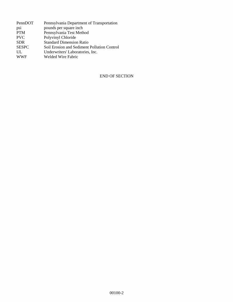
II. ABBREVIATIONS
The following abbreviations are used in the text of these specifications:
AASHTO American Association of State Highway Transportation Officials
ACI American Concrete Institute
ADA Americans with Disabilities Act
ADT Average Daily Traffic
ANSI American National Standards Institute
ASME American Society of Mechanical Engineers
ASTM American Society for Testing and Materials
AWWA American Water Works Association
BCBC Bituminous Concrete Base Course
DI Ductile Iron
ESAL Equivalent Single Axle Load
FS Federal Specifications
HES High Early Strength
HMA Hot Mix Asphalt
HDPE High Density Polyethylene
IEEE Institute of Electrical & Electronics Engineers
IES Illuminating Engineering Society
IPCEA Insulated Power Cable Engineers Association
MUTCD Manual of Uniform Traffic Control Devices
NEC National Electric Code
NECS National Electric Safety Code
NEMA National Electrical Manufacturers Association
NFPA National Fire Protection Association
O.D. Outside Diameter
OSHA Occupational Safety & Health Administration
PA DEP Pennsylvania Department of Environmental Protection
PE Polyethylene
00100-2
PennDOT Pennsylvania Department of Transportation
psi pounds per square inch
PTM Pennsylvania Test Method
PVC Polyvinyl Chloride
SDR Standard Dimension Ratio
SESPC Soil Erosion and Sediment Pollution Control
UL Underwriters' Laboratories, Inc.
WWF Welded Wire Fabric
END OF SECTION
00150-1
SECTION 00150
PLAN AND DESIGN STANDARDS
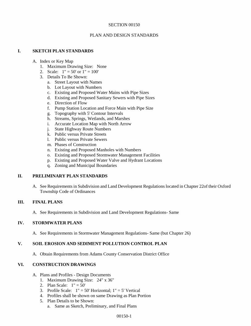
I. SKETCH PLAN STANDARDS
A. Index or Key Map
1. Maximum Drawing Size: None
2. Scale: 1" = 50' or 1" = 100'
3. Details To Be Shown:
a. Street Layout with Names
b. Lot Layout with Numbers
c. Existing and Proposed Water Mains with Pipe Sizes
d. Existing and Proposed Sanitary Sewers with Pipe Sizes
e. Direction of Flow
f. Pump Station Location and Force Main with Pipe Size
g. Topography with 5' Contour Intervals
h. Streams, Springs, Wetlands, and Marshes
i. Accurate Location Map with North Arrow
j. State Highway Route Numbers
k. Public versus Private Streets
l. Public versus Private Sewers
m. Phases of Construction
n. Existing and Proposed Manholes with Numbers
o. Existing and Proposed Stormwater Management Facilities
p. Existing and Proposed Water Valve and Hydrant Locations
q. Zoning and Municipal Boundaries
II. PRELIMINARY PLAN STANDARDS
A. See Requirements in Subdivision and Land Development Regulations located in Chapter 22of their Oxford
Township Code of Ordinances
III. FINAL PLANS
A. See Requirements in Subdivision and Land Development Regulations- Same
IV. STORMWATER PLANS
A. See Requirements in Stormwater Management Regulations- Same (but Chapter 26)
V. SOIL EROSION AND SEDIMENT POLLUTION CONTROL PLAN
A. Obtain Requirements from Adams County Conservation District Office
VI. CONSTRUCTION DRAWINGS
A. Plans and Profiles - Design Documents
1. Maximum Drawing Size: 24" x 36"
2. Plan Scale: 1" = 50'
3. Profile Scale: 1" = 50' Horizontal; 1" = 5' Vertical
4. Profiles shall be shown on same Drawing as Plan Portion
5. Plan Details to be Shown:
a. Same as Sketch, Preliminary, and Final Plans
00150-2
b. Adjoining Sheet Numbers at Sewer Intersections
c. Match Lines, if Utilized
d. Existing and Proposed Utilities with Pipe Sizes
e. Storm Drainage Facilities with Pipe Sizes
f. Stormwater Detention Facilities with Limits of Impoundment and Maximum Water Elevation
g. Pertinent Physical Features such as Buildings, Fences, Driveways, Landscaping, Poles, Street
Lighting, etc.
h. Lateral Locations
i. Sanitary Sewer and Other Utility Easements
j. Soil Erosion And Sedimentation Control Facilities Plan
k. Street Addresses for Each Lot or Unit
6. Profile Details to be Shown:
a. Existing Ground Profile
b. Finished Grade Profile
c. Sanitary Sewer Design and Manhole Numbers
d. Pipe Size, Pipe Material, Pipe Length, and Slope
e. Manhole Invert and Top Rim Elevations
f. All Utility and Storm Pipe Crossings Showing Separation Distances to Sanitary Sewers
g. Indicate Watertight Frames and Covers
h. Parallel Water Mains, Storm Drainage, and Stream Profiles
B. Cover Sheet Plan Notes
1. Plans shall clearly indicate the differences between existing and proposed facilities.
2. Access to the sanitary sewer lines must be maintained at all times. One of the following notes shall be
added to subdivision plans prior to recording:
a. "The Owner(s) shall not construct, plant, or maintain any structures, sheds, buildings, fences, trees,
shrubbery, stormwater management facilities, wiring, etc. within the sanitary sewer rights-of-way,
to ensure a free and clear access to all facilities. Bituminous paving, installation of utilities or
changes in ground contours within the sanitary sewer rights-of-way may be permitted by written
consent of the Municipality."
b. "The Owner(s) shall not construct, plant, or maintain any structures, sheds, buildings, trees,
stormwater facilities, parallel or near parallel utilities, or similar items within the sanitary sewer
rights-of-way. The Owner(s) at his/her or their own risk may install wiring, construct fences, or
plant shrubbery (less than 6' high) within said rights-of-way without any future claims against the
Municipality, because of fence or shrubbery removal. Any fences installed within said
rights-of-way shall be constructed in such a way that two sections can be easily removed, with the
maximum fence section not less than eight (8) feet in width per section. In lieu of the two
removable sections, one sixteen (16) foot wide or two eight (8) foot wide gates at each fence
crossing of the sanitary rights-of-way may be substituted."
3. Where applicable, the following notes shall be added:
a. “No construction shall begin until after the preconstruction meeting between the developer, the
contractor, the Township Engineer/Inspector, and others as may be requested to attend. The
preconstruction meeting will be scheduled upon request of the developer, and will only be held if all
of the above named participants are represented.”
b. "All work shall be installed and tested in accordance with the latest edition of the Oxford Township
Construction and Materials Specifications and shall conform to the New Oxford Municipal
Authority Plan, Design and Construction Standards for Sanitary Sewers unless specific waivers
have been granted. It is the contractor's responsibility to be aware of applicable standards and
specifications as well as the required methods of construction. All deviations from the plans must
be approved prior to construction."
c. "The Owner hereby grants the municipality, New Oxford Municipal Authority or its representative a
general access easement across the entire lot for access to the public sewer and sampling manholes."
d. "Approval of "as-built" sanitary sewer plans by the New Oxford Municipal Authority Engineer shall
be required prior to occupancy of any building. These Record Drawings shall be submitted to the
Engineer thirty (30) days prior to occupancy."
00150-3
e. "The Developers shall furnish three (3) extra sets of approved plans, showing the locations and
depths of all laterals, and final specifications to Municipal Engineer for future inspection use."
f. "The Developer shall submit three (3) sets of all grade (or cut) sheets, conforming to approved
plans, to the Municipal Engineer prior to beginning work. Any proposed changes in the approved
design shall be indicated in red on the plans submitted in reference to the note above."
g. "The Developer shall give the Municipal Engineer at least three (3) working days (72 hours) notice
prior to beginning work to assign an inspector to the project and review plans and grade sheets. No
work may begin until grade sheets have been reviewed by the Municipal Engineer."
h. "Developer offers for dedication to the New Oxford Municipal Authority all sanitary sewer
collector and/or interceptor lines constructed by the developer with appurtenances and a twenty-foot
wide perpetual easement consisting of ten feet on either side of the centerline thereof for the
maintenance, repair, replacement or enlargement thereof, together with the right of ingress, egress
and regress therefore."
C. Plan and Profiles Record Drawings (As-Builts)
1. Public Sanitary Sewer - Obtain requirements from the York Water Company or the New Oxford
Municipal Authority.
2. Public water - Obtain requirements from the York Water Company or the New Oxford Municipal
Authority.
DESIGN STANDARDS
I. PENNSYLVANIA DEPARTMENT OF ENVIRONMENTAL PROTECTION (PA DEP) DESIGN
STANDARDS
A. All Public Sewer Systems shall be designed in accordance with standards published by PA DEP in the
Domestic Wastewater Facilities Manual, latest revision.
B. In case of conflict between the PA DEP Design Standards and New Oxford Municipal Authority Design
Standards, the PA DEP Design Standards generally overrule, provided the most restrictive and conservative
design criteria is applied.
II. SUPPLEMENTAL DESIGN STANDARDS
A. Public Sanitary Sewer - Obtain requirements from the York Water Company or the New Oxford Municipal
Authority.
B. Public water - Obtain requirements from the York Water Company or the New Oxford Municipal Authority.
III. SOIL EROSION AND SEDIMENT POLLUTION CONTROL (SESPC) DESIGN STANDARDS
A. All facilities shall be designed in accordance with standards developed by PA DEP. All applicable permits
shall be secured from the Adams County Conservation District.
IV. PENNSYLVANIA DEPARTMENT OF TRANSPORTATION (PennDOT) DESIGN STANDARDS
A. All facilities to be constructed within State Highway rights-of-way shall be designed in accordance with
standards developed by PennDOT.
END OF SECTION
00160-1
SECTION 00160
UTILITY CONFLICT STATEMENT
Any discrepancies between the requirements of these specifications
and the requirements of any other authorized agency, such as public
utilities, must be resolved prior to commencement of construction
activities in order to avoid delays.
END OF SECTION
02100-1
SECTION 02100
CLEARING AND GRUBBING
PART 1 GENERAL
1.01 DESCRIPTION
A. The work of this section includes, but is not limited to:
1. Clearing
2. Grubbing
3. Stripping and stockpiling topsoil
4. Debris disposal
B. Related Work Specified Elsewhere:
1. Site excavation and placement of fill material: Section 02210
2. Trenching, backfilling and compacting: Section 02221
3. Roadway excavation, fill, and compaction: Section 02230
4. Soil erosion and sediment pollution control: Section 02270
5. Finish grading, seeding, and sodding: Section 02485
C. Definitions:
1. Clearing is defined as the removal of trees, brush, down timber, rotten wood, rubbish, any above
original ground elevation not designated to be saved. Clearing also includes removal of fences,
walls, guard posts, guide rail, signs, and other obstructions interfering with the proposed work.
2. Grubbing is defined as the removal from below the surface of the natural ground of stumps, roots
and stubs, brush, organic materials and debris.
D. Applicable Standard Details: NONE
1.02 QUALITY ASSURANCE - Section not utilized
1.03 SUBMITTALS
A. Permits:
1. Burning in the Municipality is allowed; however, specific requirements are the responsibility of
the contractor.
2. For off-site disposal, submit two copies of the agreement with each property owner releasing the
Municipality from responsibility in connection with the disposal of the debris, and permits or
approvals from regulatory agencies.
1.04 JOB CONDITIONS
A. The Contractor may clear all obstructions within the construction limits or permanent and construction
rights-of-way except those specifically designated to be saved or restored.
PART 2 PRODUCTS
2.01 MATERIALS
02100-2
A. Temporary Fencing:
1. Orange plastic safety fence, 4 foot high minimum.
2. Undamaged picket snow fence, 4' high, formed of wooden slats, tightly woven with wire cable.
3. Soil-set fence posts, studded "T" type, 6' high.
PART 3 EXECUTION
3.01 PREPARATION
A. Notify the Municipality and regulatory agencies at least 72 hours prior to beginning any clearing work.
B. Protect benchmarks, utilities, existing trees, shrubs and other landscape features designated for
preservation with temporary fencing or barricades satisfactory to the Municipality. No material shall be
stored or construction operation carried on within 4-feet of any tree to be saved or within the tree
protection fence.
C. When a private enclosure fence encroaches on the work area, notify the property owner at least 5 days in
advance of the clearing/grubbing operations to permit its removal, construct a supplemental fence, or
make such other arrangements as may be necessary for security purposes. Upon failure of the property
owner to reasonably proceed with the work required to secure his property, carefully remove the fence, in
whole or in part, and neatly pile the materials on the property.
3.02 UTILITY RELOCATIONS
A. Inform all companies, individuals and others owning or controlling facilities or structures within the
limits of the work which have to be relocated, adjusted or reconstructed in sufficient time for the utility to
organize and perform such work in conjunction with or in advance of the Contractor's operations.
B. Comply with the requirements of Pennsylvania Underground Utility Protection Law.
3.03 CLEARING
A. Confine clearing to within the construction limits.
B. Clear in a manner that will avoid damage to trees, shrubs, structures, and other installations which are to
be retained.
C. Where stumps are not required to be grubbed, flushcut with ground elevation.
3.04 GRUBBING
A. Grub areas within the construction limits to remove roots and other objectionable material to a minimum
depth of 24".
B. Remove all stumps within the cleared areas.
02100-3
3.05 STRIPPING AND STOCKPILING TOPSOIL
A. Strip topsoil to whatever depth it may occur from areas to be excavated, filled, or graded and stockpile.
B. The topsoil shall not be used as backfill.
3.06 DEBRIS DISPOSAL
A. Trees, logs, branches, brush, stumps, and other debris resulting from clearing and grubbing operations
shall become the property of the Contractor and shall be legally disposed of.
B. Do not deposit or bury on the site debris resulting from the clearing and grubbing work unless authorized
in writing by the Municipality.
C. Debris may be burned on-site if required permits are obtained, and if burning operations are conducted in
compliance with all regulations.
D. Discarded materials within the right-of-way limits necessary to perform the work shall be removed and
properly disposed of at the Contractor’s expense.
3.07 RESTORATION
A. Repair all injuries to bark, trunk, limbs, and roots or remaining plants by properly using approved
arboricultural practices and materials.
B. Replace trees, shrubs and plants designated to be saved which are permanently injured or die as a result of
construction operations with like species acceptable to the Municipality.
C. Remove protective fences, enclosures and guards upon the completion of the project.
D. Restore guard posts, guide rail, signs and other interferences to the condition equal to that existing before
construction operations.
E. Fences, mail boxes, and signs within the line of work shall be carefully removed, stored, and upon
completion of backfill, reset or replaced to their original condition and location, at the Contractor’s
expense.
END OF SECTION
02150-1
SECTION 02150
BORING AND JACKING
PART 1 GENERAL
1.01 DESCRIPTION
A. The work of this section includes, but is not limited to:
1. Approach trench excavation
2. Installation of casing pipe
3. Installation of carrier pipe
B. Related Work Specified Elsewhere:
1. Trenching, backfilling and compacting: Section 02221
C. Definitions: NONE
D. Applicable Standard Details:
OT 02150-1 Casing Installation
1.02 QUALITY ASSURANCE
A. Reference Standards:
1. Comply with applicable federal, state and local ordinances, codes, statutes, rules and regulations,
and affected jurisdictional bodies.
2. Pennsylvania Department of Transportation (PennDOT), latest revisions, Publication 408
Specifications.
3. American Railway Engineering Association, manual for railway engineering.
B. Contractor Qualifications:
1. Construction operations shall be undertaken only by an experienced Contractor with a minimum
of five operations of similar magnitude and condition.
1.03 SUBMITTALS
A. Submit history of previous work completed of equivalent nature and scope. Include qualification and
experience of key personnel.
B. Submit description of proposed construction methods, including methods to establish and maintain
vertical and horizontal alignment.
C. Manufacturers' Literature:
1. Submit manufacturers' catalog information for each type of pipe, fittings, couplings, adapters,
gaskets, casing spacers, and assembly of joints for approval by the Municipality. Include
manufacturers' recommendations for deflection in pipe joints.
02150-2
D. Certificates:
1. Submit certifications for each type of pipe, fittings, gaskets, lubricants or other joint materials from
the manufacturers attesting that each of these meets or exceeds specifications requirements.
1.04 JOB CONDITIONS
A. Conduct operations so as not to interfere with, interrupt, damage, destroy, or endanger the integrity of
surface or subsurface structures or utilities, and landscape in the immediate or adjacent areas.
B. When boring or jacking under state highways and railroads, comply with applicable right-of-way
occupancy permits.
C. If boring is obstructed, relocate or jack or tunnel crossing as approved by the Municipality.
PART 2 PRODUCTS
2.01 STEEL CASING PIPE
A. ASTM A53; 35,000 psi minimum yield strength, new materials only.
B. Full circumference welded joints.
C. Diameter and wall thickness as shown on the drawings.
2.02 CASING SPACERS
A. Non-metallic:
1. High density polyethylene (HDPE) with no metal bolts or attachments. Spacers shall strap onto
carrier pipe and slide easily into casing but shall not move during installation.
2. Spacers shall provide constant projections around entire circumference of carrier pipe. Projections
must have minimum height to pipe bells, similar to RACI type spacers as manufactured by RACI
Spacers of North America, Vernon, British Columbia, or approved equal.
B. Stainless Steel (bolt on):
1. Stainless steel shell with PVC liner, stainless steel hardware, and UHMW polymer runners.
Centered Type as manufactured by Cascade Waterworks Manufacturing Company, Yorkville,
Illinois, or equal.
C. Timber Skids:
1. Pressure treated, cut to a cross-sectional size to allow placement of the carrier pipe in the casing and
to support the barrel of the carrier pipe. Provide with notches to accommodate fastening. Treat
notches at time of pipe installation.
2.03 STEEL STRAPPING: ASTM A36
2.04 SAND (Fine aggregate)
A. Section 703.1, Publication 408 Specifications, Type A.
02150-3
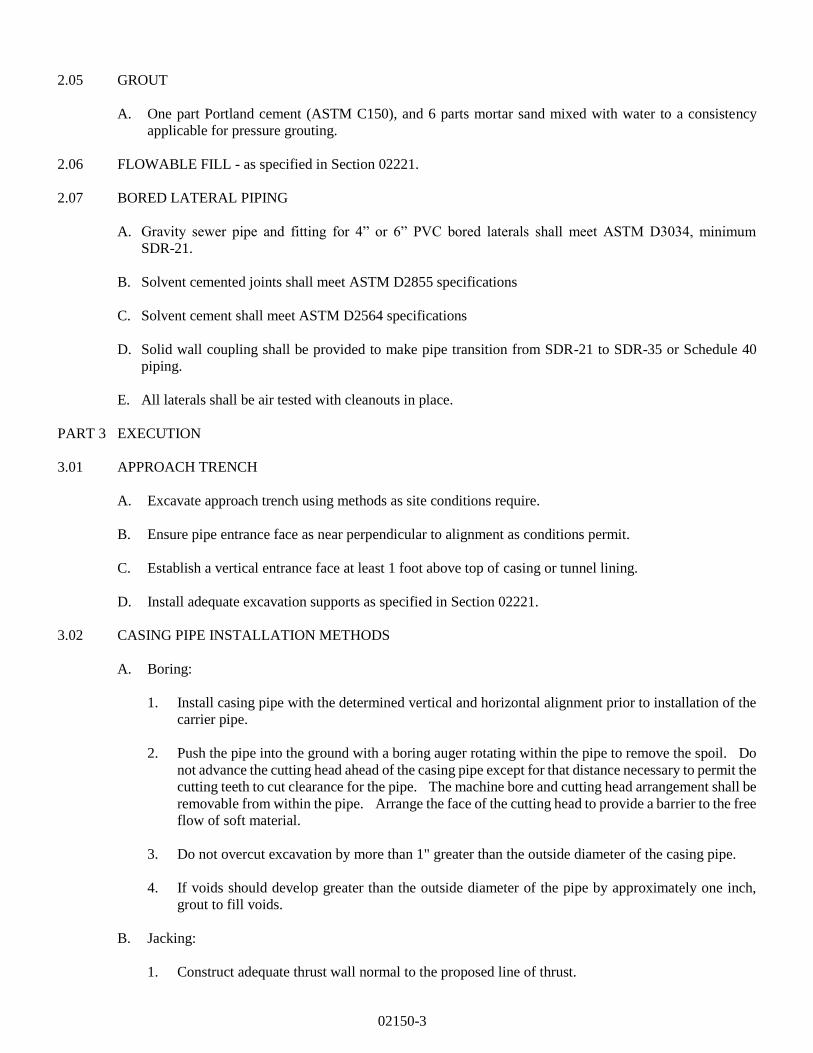
2.05 GROUT
A. One part Portland cement (ASTM C150), and 6 parts mortar sand mixed with water to a consistency
applicable for pressure grouting.
2.06 FLOWABLE FILL - as specified in Section 02221.
2.07 BORED LATERAL PIPING
A. Gravity sewer pipe and fitting for 4” or 6” PVC bored laterals shall meet ASTM D3034, minimum
SDR-21.
B. Solvent cemented joints shall meet ASTM D2855 specifications
C. Solvent cement shall meet ASTM D2564 specifications
D. Solid wall coupling shall be provided to make pipe transition from SDR-21 to SDR-35 or Schedule 40
piping.
E. All laterals shall be air tested with cleanouts in place.
PART 3 EXECUTION
3.01 APPROACH TRENCH
A. Excavate approach trench using methods as site conditions require.
B. Ensure pipe entrance face as near perpendicular to alignment as conditions permit.
C. Establish a vertical entrance face at least 1 foot above top of casing or tunnel lining.
D. Install adequate excavation supports as specified in Section 02221.
3.02 CASING PIPE INSTALLATION METHODS
A. Boring:
1. Install casing pipe with the determined vertical and horizontal alignment prior to installation of the
carrier pipe.
2. Push the pipe into the ground with a boring auger rotating within the pipe to remove the spoil. Do
not advance the cutting head ahead of the casing pipe except for that distance necessary to permit the
cutting teeth to cut clearance for the pipe. The machine bore and cutting head arrangement shall be
removable from within the pipe. Arrange the face of the cutting head to provide a barrier to the free
flow of soft material.
3. Do not overcut excavation by more than 1" greater than the outside diameter of the casing pipe.
4. If voids should develop greater than the outside diameter of the pipe by approximately one inch,
grout to fill voids.
B. Jacking:
1. Construct adequate thrust wall normal to the proposed line of thrust.
02150-4
2. Impart thrust load to the pipe through a suitable thrust ring that is sufficiently rigid to ensure
distribution of the thrust load on the pipe.
C. Drilling and Jacking:
1. Use an oil field type rock roller bit or plate bit made up of individual roller cutter units solidly
welded to the pipe which is turned and pushed for its entire length by the drilling machine to give the
bit the necessary cutting action.
2. Inject a high density slurry (oil field drilling mud) to the head as a cutter lubricant. Inject slurry at
the rear of the cutter units to prevent jetting action ahead of the pipe.
D. Mining and Jacking:
1. Utilize manual hand-mining excavation from within the casing pipe as it is advanced with jacks,
allowing minimum ground standup time ahead of the casing pipe.
3.03 CARRIER PIPE INSTALLATION WITHIN CASING PIPE
A. All provisions regarding cleaning, inspection and handling specified under pipe material sections apply
to this work.
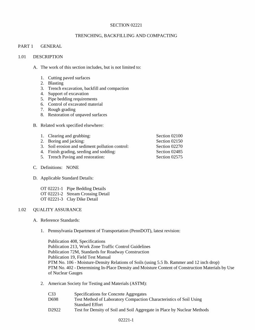
B. Place the carrier as shown on Standard Detail OT 02150-1. Exercise care to prevent damage to pipe
joints when carrier pipe is placed in casing.
C. Support pipeline within casing so that no external loads are transmitted to carrier pipe. Attach casing
spacers to barrel of carrier pipe at 6' on centers, minimum two (2) per pipe section.
D. Close ends of casing by sealing with brick masonry bulkheads, water-plug, or other approved hydraulic
cement. The downstream bulkhead shall have a 2" diameter stainless steel weephole.
E. Completely fill annular space between carrier pipe and casing pipe with limestone screenings. If in a
State highway right-of-way, fill annular space with flowable fill.
3.04 CARRIER PIPE INSTALLATION WITHOUT CASING PIPE
A. Bore the opening with a boring auger to the determined vertical and horizontal alignment.
B. Do not overcut boring excavation by more than 1" greater than the outside diameter of the lateral pipe.
C. Carefully guide the lateral pipe and joints through the opening, assembling joints prior to inserting into
the boring.
END OF SECTION
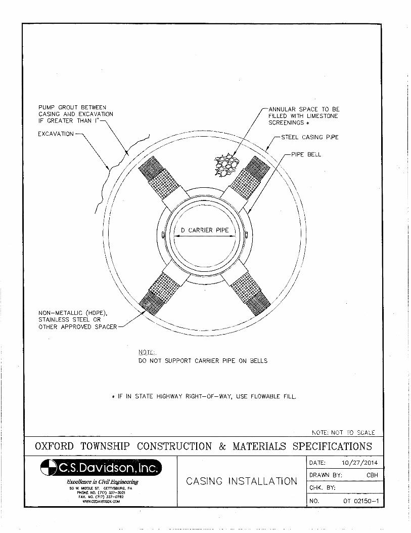
PUMP GROUT BETWEEN CASING AND EXCAVATION IF GREATER THAN I"
EXCAVATION\
NON-METALLIC (HOPE), STAINLESS STEEL OR OTHER APPROVED SPACER
NOTE;_
ANNULAR SPACE TO BE FILLED WITH LIMESTONE SCREENINGS *
STEEL CASING PIPE
DO NOT SUPPORT CARRIER PIPE ON BELLS
* IF IN STATE HIGHWAY RIGHT-OF-WAY, USE FLOWABLE FILL.
NOTE: NOT TO SCALE
OXFORD TOWNSHIP CONSTRUCTION & MATERIALS SPECIFICATIONS
(}S.Davidson, Inc. Excellence in Civil Engineering
50 W. MIDDLE ST. GETTYSBURG, PA PHONE NO. (717} 337-3021 FAX. NO. (717) 337-0782
WWW.CSOAVIDSON.COM
CASING INSTALLATION
DATE: 10/27/2014
DRAWN BY: CBH
CHK. BY:
NO. OT 02150-1
02210-1
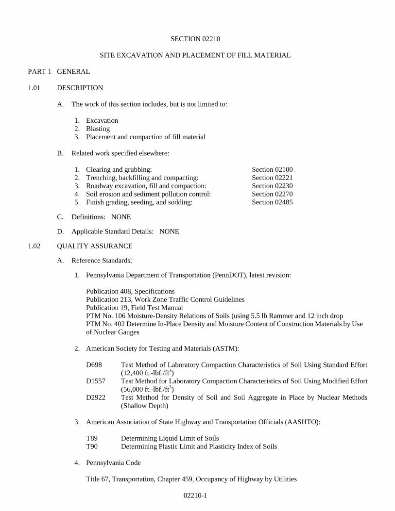
SECTION 02210
SITE EXCAVATION AND PLACEMENT OF FILL MATERIAL
PART 1 GENERAL
1.01 DESCRIPTION
A. The work of this section includes, but is not limited to:
1. Excavation
2. Blasting
3. Placement and compaction of fill material
B. Related work specified elsewhere:
1. Clearing and grubbing: Section 02100
2. Trenching, backfilling and compacting: Section 02221
3. Roadway excavation, fill and compaction: Section 02230
4. Soil erosion and sediment pollution control: Section 02270
5. Finish grading, seeding, and sodding: Section 02485
C. Definitions: NONE
D. Applicable Standard Details: NONE 1.02 QUALITY ASSURANCE
A. Reference Standards:
1. Pennsylvania Department of Transportation (PennDOT), latest revision:
Publication 408, Specifications
Publication 213, Work Zone Traffic Control Guidelines
Publication 19, Field Test Manual
PTM No. 106 Moisture-Density Relations of Soils (using 5.5 lb Rammer and 12 inch drop
PTM No. 402 Determine In-Place Density and Moisture Content of Construction Materials by Use
of Nuclear Gauges
2. American Society for Testing and Materials (ASTM):
D698 Test Method of Laboratory Compaction Characteristics of Soil Using Standard Effort
(12,400 ft.-lbf./ft3)
D1557 Test Method for Laboratory Compaction Characteristics of Soil Using Modified Effort
(56,000 ft.-lbf./ft3)
D2922 Test Method for Density of Soil and Soil Aggregate in Place by Nuclear Methods
(Shallow Depth)
3. American Association of State Highway and Transportation Officials (AASHTO):
T89 Determining Liquid Limit of Soils
T90 Determining Plastic Limit and Plasticity Index of Soils
4. Pennsylvania Code
Title 67, Transportation, Chapter 459, Occupancy of Highway by Utilities
02210-2
B. Testing Agency:
1. Compaction testing shall be performed by a Soils Testing Laboratory engaged and paid for by the
Contractor and approved by the Municipality.
C. Compaction Testing:
1. Determine compaction by the testing procedure contained in ASTM D698 or ASTM D1557
1.03 SUBMITTALS
A. Certificates:
1. Submit certified compaction testing results from the Soils Testing Laboratory.
B. One copy of approved Soil Erosion Control Plan, including approval letter from Adams County
Conservation District.
1.04 JOB CONDITIONS
A. Classification of Excavation:
1. Site excavation work includes excavation and removal of all soil, shale, rock, boulders, fill, and all
other materials encountered of whatever nature.
B. Control of Traffic:
1. Employ Traffic Control Guidelines measures in accordance with Publication 213, Work Zone
Traffic Control Guidelines.
C. Protection of Existing Utilities and Structures:
1. Take all precautions and utilize all facilities required to protect existing utilities and structures in
compliance with Pennsylvania Underground Utility Protection Law. Request cooperative steps of
the Utility and suggestions for procedures to avoid damage to its lines.
2. Allow free access to Utility personnel at all times for purposes of maintenance, repair and
inspection.
PART 2 PRODUCTS
2.01 ACCEPTABLE MATERIALS
For purposes of construction control, subject to approval and inspection by the Municipality or other
specifically designated personnel, the following materials may be deemed acceptable for use in placement of
fills:
A. Soil. Soil shall include all inorganic material having a maximum size that can be readily placed and
compacted in loose 8 inch layers and of which more than 35 percent shall pass the No. 200 sieve. Soil
shall have a minimum dry weight density of 98 pounds per cubic foot as determined in accordance with
PTM No. 106, Method B and a maximum liquid limit of 65 as determined in accordance with AASHTO
Designation T89. The plasticity index, as determined by AASHTO Designation T90 for soils having
liquid limits of 41 to 65 inclusive, shall be not less than that determined by the formula: Plasticity Index
= Liquid Limit - 30.
02210-3
B. Granular Material. Granular material shall include all natural or synthetic mineral aggregates having a
maximum size that can be readily placed and compacted in loose 8 inch layers and of which 35 percent
or less shall pass the No. 200 sieve.
C. Shale. Shale shall include all rock-like materials formed by the natural consolidation of mud, clay, silt
and fine sand and usually thinly laminated, comparatively soft and easily split, having a maximum size
that can be readily placed and compacted in loose 8 inch layers.
D. Rock. Rock shall include all igneous, metamorphic and sedimentary rock having a maximum size that
can be readily placed and compacted in loose 8 inch layers and which generally has sufficient fines to
normally fill all the voids in each layer.
E. Random Materials. Random material shall include any combination of the above classifications and
may include old concrete, brick, etc., from demolition having a maximum size that can be readily placed
and compacted in loose 8 inch layers, and which have been approved by the Municipality.
F. Flowable Fill. As defined in Section 02221.
PART 3 EXECUTION
3.01 MAINTENANCE AND PROTECTION OF TRAFFIC
A. Coordinate the work to ensure the least inconvenience to traffic and maintain traffic on one or more
unobstructed lanes unless closing of the roadway is authorized.
B. Maintain access to all streets and private drives and for emergency vehicles.
C. Provide and maintain signs, flashing warning lights, barricades, markers, and other protective devices as
required to conform with construction operations and to keep traffic flowing with minimum restrictions.
D. Comply with State and local codes, permits and regulations.
3.02 SALVAGE TOPSOIL
A. Within the areas indicated for grading, strip topsoil to the depth of suitable topsoil material and stockpile
for subsequent topsoiling operations. See Section 02100.
3.03 PLACEMENT OF FILL MATERIAL
A. After removal of topsoil, areas to receive fill shall be thoroughly rolled, and any soft spots disclosed by
rolling shall be excavated and the unsuitable material removed and disposed of in a waste area. The
excavated area shall be filled with suitable fill material approved by the Municipality and recompacted.
Suitable fill material shall be spread in layers of not more than 8 inches (loose) over the full area of the
fill, and compacted to the required density by the use of compaction equipment. All fill material shall
be compacted to not less than 95% of its maximum dry weight density at its optimum moisture content,
plus or minus 2%, as determined by ASTM D698, under roadways, shoulders, driveways, curbs,
sidewalks, gravel and sand parking areas and not less than 90% in yards, fields and sand areas.
When the material is too coarse to satisfactorily use these methods, compaction will be determined by
the Municipality based on non-movement of the material under the compaction equipment.
B. Fill material placed in areas inaccessible to the compaction equipment shall be placed in uniform loose
layers not exceeding 4 inches in depth and compacted by means of approved mechanical tampers to the
density requirements herein specified.
02210-4
C. When a previously constructed fill requires additional material to bring it to required elevation, the top
of the fill shall be thoroughly scarified before the required additional material is placed.
D. Material containing moisture in excess of that percentage which will ensure satisfactory compaction
shall not be placed in the fill and fill material shall not be placed on material that has become unstable
due to excessive moisture.
E. Frozen fill material shall not be placed in fills, and fill material shall not be placed on frozen material.
If during construction the top of the fill freezes, all frozen material shall be removed before additional
material is placed.
F. In no case shall waste material be disposed of in the flood channel or floodway area of any stream.
G. Shale and random material containing an excessive quantity of large fragments shall be so placed that
the coarser material is in areas where no building foundations or utility trenches are to be located. The
large pieces shall then be broken down by the use of approved equipment until all voids are filled.
Mixtures of shale and rock shall be placed in accordance with the requirements for placing shale.
H. Where fill is to be constructed on a slope, the slope shall be benched to the width and depth shown on the
drawings or as approved by the Municipality.
3.04 EXCAVATION
A. Perform excavation of borrow material in a manner satisfactory to the Municipality. Strip borrow pits
of brush, trees, roots, grass and other vegetation prior to removal of material for use in fill. During the
excavation operation, grade the borrow area to ensure free drainage of water from the area. Place and
maintain erosion control devices after completion of the excavation, grade the excavated area, including
side slopes, to drain and present a uniformly trim appearance merging into the surrounding terrain. After
borrowing operations are complete, regrade area, if necessary, to prevent erosion.
3.05 BLASTING
A. Notify Municipality at least 24 hours in advance of any blasting activity with the Municipality.
B. Blasting is the sole responsibility of the Contractor and no duty is assumed or to be exercised by
Municipality relative thereto.
C. Blasting work shall be supervised by licensed and experienced personnel and performed in conformance
with applicable Federal, State and local codes.
3.06 CONTROL OF EXCAVATED MATERIAL
A. Provide temporary barricades to prevent excavated material from encroaching on private property,
walks, gutters, and storm drains.
B. Maintain accessibility to all fire hydrants, valve pit covers, valve boxes, curb boxes, fire and police call
boxes, and other utility controls at all times. Keep gutters clear or provide other satisfactory facilities
for street drainage. Do not obstruct natural water courses. Where necessary, provide temporary
channels to allow the flow of water either along or across the site of the work.
C. All work shall be reviewed and approved by the Adams County Conservation District.
02210-5
3.07 DEWATERING
A. Keep excavations dry and free of water. Dispose of precipitation and subsurface water clear of the
work.
B. Intercept and divert surface drainage away from excavations. Design surface drainage systems so that
they do not cause erosion on or off the site, or cause unwanted flow of water.
C. Comply with Federal and State requirements for dewatering to any watercourse, prevention of stream
degradation, and erosion and sediment control.
3.08 TOPSOILING
A. Topsoiling as specified in Section 02485, Finish Grading, Seeding and Sodding.
3.09 DISPOSAL OF EXCAVATED MATERIAL
A. Excavated material remaining after completion of placement of fills shall be removed from the
construction area, and properly disposed of.
3.10 FOREIGN BORROW MATERIAL
A. Foreign borrow consists of excavation, placement and compaction in fill areas of approved material
obtained from sources outside the project limits.
B. The Contractor shall make his own arrangements for obtaining all foreign borrow material.
END OF SECTION
02221-1
SECTION 02221
TRENCHING, BACKFILLING AND COMPACTING
PART 1 GENERAL
1.01 DESCRIPTION
A. The work of this section includes, but is not limited to:
1. Cutting paved surfaces
2. Blasting
3. Trench excavation, backfill and compaction
4. Support of excavation
5. Pipe bedding requirements
6. Control of excavated material
7. Rough grading
8. Restoration of unpaved surfaces
B. Related work specified elsewhere:
1. Clearing and grubbing: Section 02100
2. Boring and jacking: Section 02150
3. Soil erosion and sediment pollution control: Section 02270
4. Finish grading, seeding and sodding: Section 02485
5. Trench Paving and restoration: Section 02575
C. Definitions: NONE
D. Applicable Standard Details:
OT 02221-1 Pipe Bedding Details
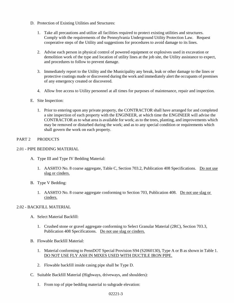
OT 02221-2 Stream Crossing Detail
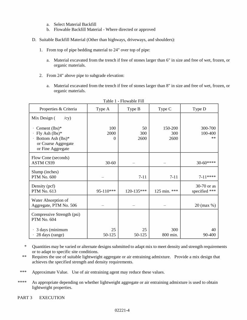
OT 02221-3 Clay Dike Detail
1.02 QUALITY ASSURANCE
A. Reference Standards:
1. Pennsylvania Department of Transportation (PennDOT), latest revision:
Publication 408, Specifications
Publication 213, Work Zone Traffic Control Guidelines
Publication 72M, Standards for Roadway Construction
Publication 19, Field Test Manual
PTM No. 106 - Moisture-Density Relations of Soils (using 5.5 lb. Rammer and 12 inch drop)
PTM No. 402 - Determining In-Place Density and Moisture Content of Construction Materials by Use
of Nuclear Gauges
2. American Society for Testing and Materials (ASTM):
C33 Specifications for Concrete Aggregates
D698 Test Method of Laboratory Compaction Characteristics of Soil Using
Standard Effort
D2922 Test for Density of Soil and Soil Aggregate in Place by Nuclear Methods
02221-2
D1557 Modified Proctor Compaction Test
3. Pennsylvania Code
Title 67, Transportation, Chapter 459, Occupancy of Highways by Utilities
B. Testing Agency:
1. Compaction testing shall be performed by an approved Soils Testing Laboratory approved and paid for
by the CONTRACTOR and approved by the ENGINEER.
C. Compaction Testing:
1. Conduct compaction tests as directed by the Municipality during backfilling operations.
2. Determine compaction in state highways and shoulders by the testing procedure contained in PTM No.
106, Method B or PTM No. 402.
3. Determine compaction in areas other than state highways and shoulders by the testing procedure
contained in ASTM D698 or ASTM D2922.
1.03 SUBMITTALS
A. Certificates:
1. Submit certification from aggregate suppliers attesting that the pipe bedding and select material stone
backfill materials conform to the specifications herein.
B. Compaction Equipment List:
1. Submit a list of all equipment to be utilized for compacting, including manufacturers' lift thickness
limitations.
1.04 JOB CONDITIONS
A. Classification of Excavation:
1. Excavation work includes excavation and removal of all soil, shale, rock, boulders, fill, and all other
materials encountered of whatever nature.
B. Compaction of Backfill:
1. The degree of compaction required at each location is indicated in the Backfill and Surface Restoration
Requirements Table in Section 02575.
C. Control of Traffic:
1. Employ Traffic Control Guidelines measures in accordance with Publication 213, Work Zone Traffic
Control Guidelines.
02221-3
D. Protection of Existing Utilities and Structures:
1. Take all precautions and utilize all facilities required to protect existing utilities and structures.
Comply with the requirements of the Pennsylvania Underground Utility Protection Law. Request
cooperative steps of the Utility and suggestions for procedures to avoid damage to its lines.
2. Advise each person in physical control of powered equipment or explosives used in excavation or
demolition work of the type and location of utility lines at the job site, the Utility assistance to expect,
and procedures to follow to prevent damage.
3. Immediately report to the Utility and the Municipality any break, leak or other damage to the lines or
protective coatings made or discovered during the work and immediately alert the occupants of premises
of any emergency created or discovered.
4. Allow free access to Utility personnel at all times for purposes of maintenance, repair and inspection.
E. Site Inspection:
1. Prior to entering upon any private property, the CONTRACTOR shall have arranged for and completed
a site inspection of each property with the ENGINEER, at which time the ENGINEER will advise the
CONTRACTOR as to what area is available for work; as to the trees, planting, and improvements which
may be removed or disturbed during the work; and as to any special condition or requirements which
shall govern the work on each property.
PART 2 PRODUCTS
2.01 - PIPE BEDDING MATERIAL
A. Type III and Type IV Bedding Material:
1. AASHTO No. 8 coarse aggregate, Table C, Section 703.2, Publication 408 Specifications. Do not use
slag or cinders.
B. Type V Bedding:
1. AASHTO No. 8 coarse aggregate conforming to Section 703, Publication 408. Do not use slag or
cinders.
2.02 - BACKFILL MATERIAL
A. Select Material Backfill:
1. Crushed stone or gravel aggregate conforming to Select Granular Material (2RC), Section 703.3,
Publication 408 Specifications. Do not use slag or cinders.
B. Flowable Backfill Material:
1. Material conforming to PennDOT Special Provision S94 (S2060130), Type A or B as shown in Table 1.
DO NOT USE FLY ASH IN MIXES USED WITH DUCTILE IRON PIPE.
2. Flowable backfill inside casing pipe shall be Type D.
C. Suitable Backfill Material (Highways, driveways, and shoulders):
1. From top of pipe bedding material to subgrade elevation:
02221-4
a. Select Material Backfill
b. Flowable Backfill Material - Where directed or approved
D. Suitable Backfill Material (Other than highways, driveways, and shoulders):
1. From top of pipe bedding material to 24" over top of pipe:
a. Material excavated from the trench if free of stones larger than 6" in size and free of wet, frozen, or
organic materials.
2. From 24" above pipe to subgrade elevation:
a. Material excavated from the trench if free of stones larger than 8" in size and free of wet, frozen, or
organic materials.
Table 1 - Flowable Fill
Properties & Criteria
Type A
Type B
Type C
Type D Mix Design ( /cy)
· Cement (lbs)*
· Fly Ash (lbs)*
· Bottom Ash (lbs)*
or Coarse Aggregate
or Fine Aggregate
100
2000
0
50
300
2600
150-200
300
2600
300-700
100-400
**
Flow Cone (seconds)
ASTM C939
30-60
–
–
30-60**** Slump (inches)
PTM No. 600
–
7-11
7-11
7-11**** Density (pcf)
PTM No. 613
95-110***
120-135***
125 min. ***
30-70 or as
specified *** Water Absorption of
Aggregate, PTM No. 506
–
–
–
20 (max %) Compressive Strength (psi)
PTM No. 604
· 3 days (minimum
· 28 days (range)
25
50-125
25
50-125
300
800 min.
40
90-400
* Quantities may be varied or alternate designs submitted to adapt mix to meet density and strength requirements
or to adapt to specific site conditions.
** Requires the use of suitable lightweight aggregate or air entraining admixture. Provide a mix design that
achieves the specified strength and density requirements.
*** Approximate Value. Use of air entraining agent may reduce these values.
**** As appropriate depending on whether lightweight aggregate or air entraining admixture is used to obtain
lightweight properties.
PART 3 EXECUTION
02221-5
3.01 MAINTENANCE AND PROTECTION OF TRAFFIC
A. Maintain traffic in one or more unobstructed lanes and provide access to all streets and private drives.
B. Provide and maintain protective devices as required by state and local codes, permits, and regulations.
C. Notify Municipality at least 72 hours in advance of any operations requiring changes to existing traffic
patterns.
3.02 CUTTING PAVED SURFACES PRIOR TO TRENCHING
A. Where installation of pipelines, miscellaneous structures, and appurtenances necessitate breaking a paved
surface, make cuts in a neat uniform fashion forming straight lines parallel with the centerline of the
trench. Cut offsets at right angles to the centerline of the trench.
B. Protect edges of cut pavement during excavation to prevent raveling or breaking; square edges prior to
pavement replacement.
C. The requirement for neat line cuts, in other than state highways, may be waived if the final paving
restoration indicates overlay beyond the trench width.
3.03 BLASTING
A. See Section 02210.
3.04 TRENCH EXCAVATION
A. Depth of Excavation:
1. Gravity Pipelines:
a. Excavate mainline trenches to the required depth and grade for the invert of the pipe plus that
excavation necessary for placement of pipe bedding material.
b. Excavation for laterals shall provide a straight uniform grade from the main pipeline to the
right-of-way line (in accordance with Section 02610), plus that excavation necessary for
placement of pipe bedding material.
2. Pressure Pipelines:
a. Excavate trenches to the minimum depth necessary to place required pipe bedding material and to
provide a minimum of 42" from the top of the pipe to the finished ground elevation, except where
specific depths are otherwise shown on the drawings.
3. Where unsuitable bearing material is encountered in the trench bottom, continue excavation until the
unsuitable material is removed, solid bearing is obtained or can be established, or concrete cradle can
be placed. If no concrete cradle is to be installed, refill the trench to required pipeline grade with pipe
bedding material.
4. Where the Contractor, by error or intent, excavates beyond the minimum required depth, backfill the
trench to the required pipeline grade with pipe bedding material.
02221-6
B. Width of Excavation:
1. Excavate trenches, including laterals, to a width necessary for placement and jointing of the pipe, and
for placing and compacting pipe bedding and trench backfill around the pipe, but not less than 16" or
more than 24" plus the pipe outside diameter from the bottom of the trench to a point 12" above the
crown of the pipe.
2. Shape trench walls completely vertical from trench bottom to at least 2' above the top of the pipe.
Trench walls from 2' above the top of the pipe to grade to be benched and sloped, or shaved, to comply
with Federal and State laws and codes.
3. For pressure pipeline fittings, excavate trenches to a width that will permit placement of concrete
thrust blocks. Provide earth surfaces for thrust blocks that are perpendicular to the direction of thrust
and are free of loose or soft material.
3.05 SUPPORT OF EXCAVATION
A. The adequacy of the design of sheeting, shoring and bracing installations relative to the nature of the
material to be encountered and retained is the sole responsibility of the Contractor and no duty is assumed
or to be exercised by the Municipality relative thereto.
B. Support excavations with sheeting, shoring, and bracing or a "trench box" as required to comply with
Federal and State laws and codes.
C. Install adequate excavation supports to prevent ground movement or settlement of adjacent structures,
pipelines or utilities. Damage due to settlement because of failure to provide support or through negligence
or fault of the Contractor in any other manner, shall be repaired at the Contractor's expense.
D. Removal of sheeting, shoring and bracing as backfilling proceeds is the Contractor’s responsibility.
3.06 CONTROL OF EXCAVATED MATERIAL
A. Keep the ground surface on both sides of the excavation free of excavated material to comply with Federal
and State laws and codes.
B. Provide temporary barricades to prevent excavated material from encroaching on private property, walks,
gutters, and storm drains.
C. Maintain accessibility to all fire hydrants, valve pit covers, valve boxes, curb boxes, fire and police call
boxes, and other utility controls at all times. Keep gutters clear or provide other satisfactory facilities for
street drainage. Do not obstruct natural water courses. Where necessary, provide temporary channels to
allow the flow of water either along or across the site of the work.
D. In areas where pipelines parallel or cross streams, ensure that no material slides, is washed, or is dumped into
the stream course. Remove cofferdams immediately upon completion of pipeline construction.
E. Work shall be in accordance with approved SESPC plan and guidelines of the Adams County Conservation
District.
3.07 DEWATERING
A. Keep excavations dry and free of water. Dispose of precipitation and subsurface water clear of the work.
Comply with Section 02270, Soil Erosion and Sedimentation Control.
02221-7
B. Maintain pipe trenches dry until pipe has been jointed, inspected, and backfilled, and concrete work has been
completed. Prevent trench water from entering pipelines under construction.
C. Intercept and divert surface drainage away from excavations. Design surface drainage systems so that they
do not cause erosion on or off the site, or cause unwanted flow of water.
D. Comply with Federal and State requirements for dewatering to any watercourse, prevention of stream
degradation, and erosion and sediment control.
3.08 PIPE BEDDING REQUIREMENTS
A. Type III Bedding:
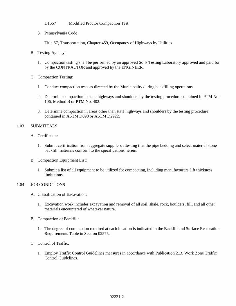
1. Depth of pipe bedding aggregate as shown on Standard Detail OT 02221-1.
2. Provide Type III bedding when installing reinforced concrete storm drain pipe.
B. Type IV Bedding:
1. Depth of pipe bedding aggregate as shown on Standard Detail OT 02221-1.
2. Provide Type IV bedding when installing all other pipes larger than 2" diameter.
C. Type V Bedding:
1. Depth of pipe bedding aggregate as shown on Standard Detail OT 02221-1.
2. Provide Type V bedding when installing piping 2" diameter and smaller.
D. Shape recesses for the joints or bell of the pipe by hand. Assure that the pipe is supported on the lower
quadrant (under “haunches”) and the pipe bottom for the entire length of the barrel. Fill all voids below the
pipe.
E. Pipe embedment material shall be placed, worked by hand or compacted until a minimum density of 90% in
yards and 95% under driveways, shoulders, roadways and sidewalks is achieved (at optimum moisture
content, ± 2%, standard proctor).
3.09 PIPE LAYING
A. Provide required pipe bedding placed in accordance with the Standard Details.
B. Lay pipe as specified in the appropriate Section of these Specifications for pipeline construction.
3.10 THRUST RESTRAINT
A. Provide pressure pipe with concrete thrust blocking or use restrained joint fittings at all bends, tees, valves,
and changes in direction, in accordance with the drawings.
02221-8
3.11 BACKFILLING TRENCHES
A. After pipe installation and inspection, backfill trenches to 12" above the crown of the pipe with specified
backfill material, as per Pipe Bedding Detail (OT 02221-1), placed and carefully compact with approved
compaction equipment in layers of suitable thickness to provide specified compaction. Backfill and
compact the remainder of the trench with specified backfill material. Refer to drawings and Backfill and
Surface Restoration Requirements Table in Section 02575 for trench backfill material and compaction
requirements at each specific location.
B. Lift Thickness Limitations:
1. Submit a list of the compaction equipment to be utilized on the project, the recommendations of the
equipment manufacturer as to the maximum lift thickness which can be placed, and the method of
compaction to be used with this equipment to achieve the required compaction. In no case shall
maximum lift thickness placed exceed the maximum limits specified by the manufacturer's
recommendations. However, if the equipment manufacturer's lift thickness recommendation is
followed and the specified compaction is not obtained, the Contractor shall, at his own expense, remove,
replace, and retest as many times as is required to obtain the specified compaction.
2. Lift thickness limitations specified for state highways, shoulders, or embankments shall govern over the
compaction equipment manufacturer's recommendations.
C. Jetting:
1. When approved by the Municipality in writing, jetting methods may be used to consolidate backfill.
Quality assurance methods to verify adequate compaction will be a condition of the approval by the
Municipality.
D. Uncompacted Backfill:
1. Where uncompacted backfill is indicated on the drawings, backfill the trench from one foot above the
pipe to the top of the trench with material excavated from the trench, crowned over the trench to a
sufficient height to allow for settlement to grade after consolidation, providing for surface water
drainage.
E. Unsuitable Backfill Material:
1. Where the Municipality deems backfill material to be unsuitable and rejects all or part thereof due to
conditions prevailing at the time of construction, remove the unsuitable material and replace with select
material backfill.
3.12 DISPOSAL OF EXCAVATED MATERIAL
A. Excavated material remaining after completion of backfilling shall be removed from the construction area,
and legally disposed of.
3.13 ROUGH GRADING
A. Rough subgrade areas disturbed by construction to a uniform finish. Form the bases for terraces, banks,
and lawns.
B. Grade areas to be paved to depths required where placing subbase and paving materials.
C. Rough grade areas to be topsoiled and seeded to 4" below indicated finish contours.
02221-9
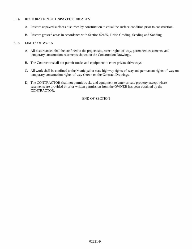
3.14 RESTORATION OF UNPAVED SURFACES
A. Restore unpaved surfaces disturbed by construction to equal the surface condition prior to construction.
B. Restore grassed areas in accordance with Section 02485, Finish Grading, Seeding and Sodding.
3.15 LIMITS OF WORK
A. All disturbances shall be confined to the project site, street rights-of-way, permanent easements, and
temporary construction easements shown on the Construction Drawings.
B. The Contractor shall not permit trucks and equipment to enter private driveways.
C. All work shall be confined to the Municipal or state highway rights-of-way and permanent rights-of-way on
temporary construction rights-of-way shown on the Contract Drawings.
D. The CONTRACTOR shall not permit trucks and equipment to enter private property except where
easements are provided or prior written permission from the OWNER has been obtained by the
CONTRACTOR.
END OF SECTION
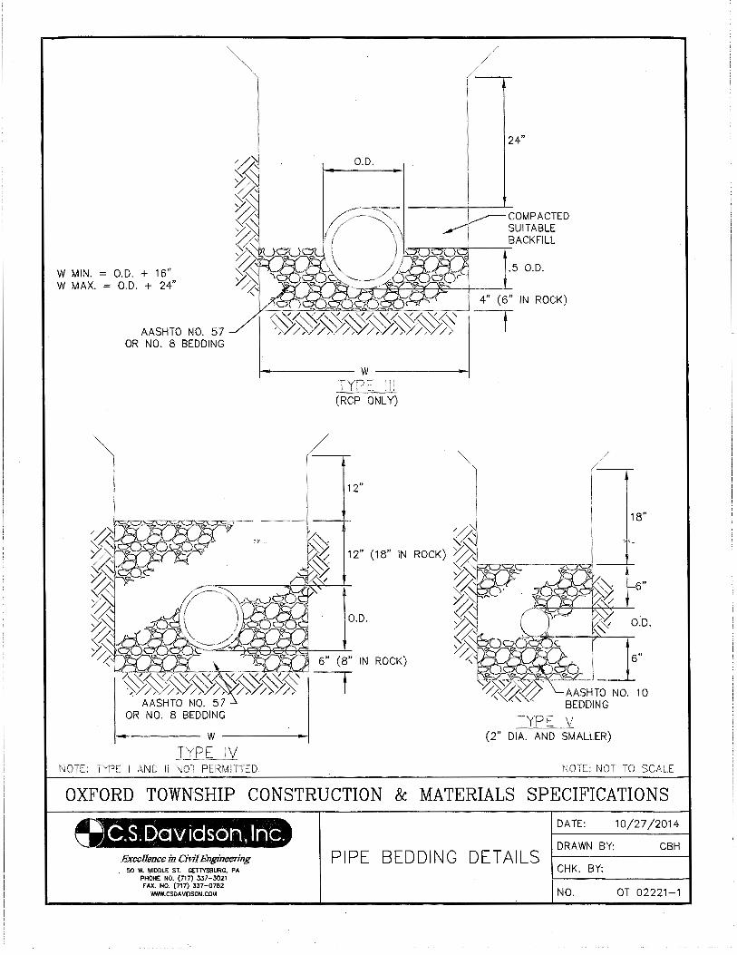
W MIN. = O.D. + 16" W MAX. = O.D. + 24"
AASHTO NO. 57 OR NO. 8 BEDDING
\
NOTE: TYPE I AND II NOT PERMITTED.
O.D.
12"
6" (8" IN ROCK)
t
24"
COMPACTED SUITABLE BACKFILL
.5 O.D.
4" (6" IN ROCK)
AASHTO NO. 10 BEDDING
(2" DIA. AND SMALLER)
NOTE: NOT TO
OXFORD TOWNSHIP CONSTRUCTION & MATERIALS SPECIFICATIONS
C.S.Davictsan, Inc;. Excellence in Civil Engineering
• 50 W. MIDDLE ST. GETTYSBURG. PA PHONE NO. (717} 337-3021 FAX. NO. (717) 337-0782
WWW.CSOA V10SON.COM
PIPE BEDDING DETAILS
DATE: 10/27/2014
DRAWN BY: CBH
CHK. BY:
NO. OT 02221-1
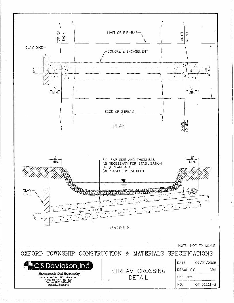
5' MIN.
DIKE
LIMIT OF RIP-RAP\
---
ENCASEMENT
RIP-RAP SIZE AND THICKNESS AS NECESSARY FOR STABILIZATION OF STREAM BED (APPROVED BY PA DEP)
z ~
0
5' MIN.
1\iOTE: NOT TO SCALE
OXFORD TOWNSHIP CONSTRUCTION & MATERIALS SPECIFICATIONS
~.S.I:Davictson, Inc. ExceUC11cc in Civil Engineering
50 W. MIDDLE ST. GETTYSBURG. PA PHONE NO. (717) 337-3021 FAX. NO. (717) 337-0762
WWW.CSDA VIOSON.COt.t
STREAM CROSSING DETAIL
DATE: 07/31/2006
DRAWN BY: CBH
CHK. BY:
NO. OT 02221-2
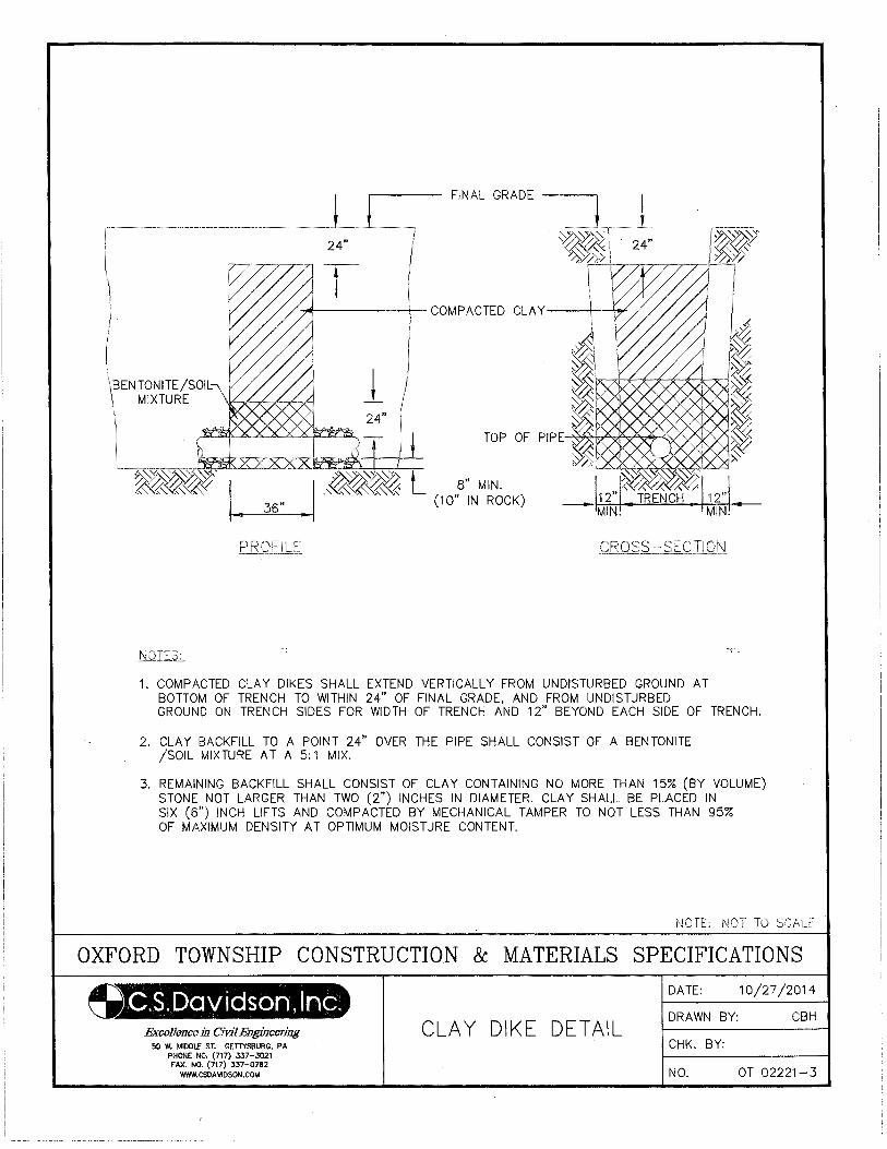
FINAL GRADE ~ ___ j_ . ~~T 24" ~~)>I
\BENTONITE/SOil: \ MIXTURE -~ \ 24"
-I ·~~~~ L 8" MIN. •
-~~'(<\_"<;(: 36.. (10" IN ROCK)
t----==--...,
1. COMPACTED CLAY DIKES SHALL EXTEND VERTICALLY FROM UNDISTURBED GROUND AT BOTTOM OF TRENCH TO WITHIN 24" OF FINAL GRADE, AND FROM UNDISTURBED GROUND ON TRENCH SIDES FOR WIDTH OF TRENCH AND 12" BEYOND EACH SIDE OF TRENCH.
2. CLAY BACKFILL TO A POINT 24" OVER THE PIPE SHALL CONSIST OF A BENTONITE /SOIL MIXTURE AT A 5: 1 MIX.
3. REMAINING BACKFILL SHALL CONSIST OF CLAY CONTAINING NO MORE THAN 15% (BY VOLUME) STONE NOT LARGER THAN TWO (2") INCHES IN DIAMETER. CLAY SHALL BE PLACED IN SIX (6") INCH LIFTS AND COMPACTED BY MECHANICAL TAMPER TO NOT LESS THAN 95% OF MAXIMUM DENSITY AT OPTIMUM MOISTURE CONTENT.
NOTE: NOT TO SCALE
OXFORD TOWNSHIP CONSTRUCTION & MATERIALS SPECIFICATIONS
u.S. Davids om, I me. Excellence in CiVJ7 Engineering
50 W. MIDDLE ST. GETTYSBURG, PA PHONE NO. (717} 337-3021 FAX. NO. (717) 337-0782
WWW.CSOAVIDSON.COM
CLAY DIKE DETAIL
DATE: 10/27/2014
DRAWN BY: CBH
CHK. BY:
NO. OT 02221-3
02230-1
SECTION 02230
ROADWAY EXCAVATION, FILL AND COMPACTION
PART 1 GENERAL
1.01 DESCRIPTION
A. The work of this Section includes but is not limited to:
1. Excavation
2. Compaction
3. Fill
4. Subgrade Preparation
5. Base Preparation
B. Related work specified elsewhere:
1. Clearing and grubbing: Section 02100
2. Site excavation and placement of fill material: Section 02210
3. Finish grading, seeding and sodding: Section 02485
4. Bituminous paving and surfacing: Section 02500
5. Soil erosion and sediment pollution control: Section 02270
C. Definitions:
1. Roadway: Area under and within ten feet of the edge of paving.
2. Roadway Subgrade: The prepared earth surfaces on or over which additional roadway materials will
be placed or work is to be performed.
D. Applicable Standard Details:
OT 02500-1 Typical Street Cross Section
OT 02500-2 Street Widening Detail
1.02 QUALITY ASSURANCE
A. Reference Standards:
1. American Association of State Highway and Transportation Officials (AASHTO):
T99 Moisture-Density Relations of Soils, Using a 5.5-lb. Rammer and a 12-in. Drop
T191 Standard Method of Test for Density of Soil In-Place by the Sand Cone Method.
2. American Society for Testing and Materials (ASTM):
D2167 Test Method for Density and Unit Weight of Soil in Place by the Rubber-Balloon Method.
D2922 Test Method for Density of Soil and Soil-Aggregate in Place by Nuclear Methods (Shallow
Depth).
3. Pennsylvania Department of Transportation (PennDOT), latest revision:
Publication 408, Specifications
02230-2
B. Inspections:
1. Inspection by the Municipality will, at a minimum, be made of the subgrade prior to placement of the
base course, and of the base course prior to placement of the binder surface.
1.03 SUBMITTALS
A. Certificates:
1. Submit certification from aggregate suppliers attesting that materials conform to PennDOT
specifications herein. PennDOT certification (CS-4171) shall be provided with each load of crushed
aggregate delivered to the job site.
B. One copy of the approved SESPC plan, including approval letter.
1.04 JOB CONDITIONS
A. As specified in Section 02210.
B. Control of traffic:
1. Reasonable access must be maintained for adjacent property OWNERs and commercial properties.
2. All excavations in access drive, driveways, and state highway rights-of-way shall be backfilled or plated
at the end of each workday.
PART 2 PRODUCTS
2.01 ACCEPTABLE MATERIALS
A. Roadway Fill Areas: As specified previously under Site Excavation and Placement of Fill Material,
Section 02210.
B. Embankment Fill Areas: As specified previously under Site Excavation and Placement of Fill Material,
Section 02210.
C. Excavated Areas: Suitability of material for subgrade purposes shall be determined by non-movement of
the material under compaction equipment.
D. Course Aggregate: Hard, tough, durable, and uncoated inert particles reasonably free from clay, silt,
vegetation, and other deleterious substances. Course aggregate shall be obtained from an approved source.
2.02 GEOTEXTILES
A. For all areas of wet subgrade – Class 4 Type B as defined in PennDOT Publication 408, Section 735, and as
approved by the ENGINEER.
B. For pavement base drains – Class 1as defined in PennDOT Publication 408, Section 735, and as approved by
the ENGINEER.
PART 3 EXECUTION
3.01 SUBGRADE
A. Perform soil erosion control work in accordance with the approved soil erosion plan.
02230-3
B. Roadway Excavation: Excavate or otherwise remove and satisfactorily dispose of materials located within
the limits indicated on the drawings for roadways.
1. Excavate to roadway subgrade depths required, and cut drainage channels and waterways as detailed on
the drawings. Proof roll subgrade to the satisfaction of the Municipality.
2. Remove rock encountered in roadway excavation to a depth six inches below finished subgrade
elevation.
3. Excavate unsuitable subgrade material. Refill such areas to required elevation with acceptable
materials.
4. Place geotextile layer in wet areas prior to placing final base course.
C. Roadway Grading: Shape subgrade of roadways, intersections, approaches, entrances and adjoining
pedestrian walkways to no more than 0.10 foot above or below the design elevations.
D. Roadway Fill: Construction requirements for roadway fill shall be as follows:
1. Form the roadway fill with acceptable materials.
2. Compact material to a minimum final density of not less than 95% of the maximum dry weight density
at its optimum moisture content plus or minus 2%, per ASTM D698 or D1557. Proof roll roadway fill
to the satisfaction of the Municipality.
E. Roadway Embankment: Construction requirements for roadway embankment shall be as follows:
1. Break up shale and other rock-like materials formed by natural consolidation of mud, clay, silt and fine
sand into a maximum size that can be readily placed and compacted in loose eight-inch layers.
2. Place rock to form the base of roadway embankments. Place in uniform loose layers not exceeding in
depth the approximate average size of the larger rock, but not exceeding 8 inches deep.
3. Smooth and level each layer adding soil or granular material conforming to Section 02210, in sufficient
quantity to supplement the smaller rock pieces, filling the voids and pockets.
4. Form the top 18 inches of roadway embankments with soil or granular material conforming to Section
02210.
5. Compact embankment material to a minimum final density of not less than 95% of the maximum dry
weight density at its optimum moisture content plus or minus 2%, per ASTM D698 or D1557. Proof roll
embankments to the satisfaction of the Municipality.
6. During foreign borrow excavation operations, keep the borrow area graded to ensure free water
drainage. Following completion of work in the borrow area, grade the area to present a uniformly trim
appearance merging into the surrounding terrain and to prevent erosion.
3.02 BASE COURSES
A. Subbase Course
1. Compact subgrade material to a minimum final density of not less than 95% of the maximum dry weight
density at its optimum moisture content plus or minus 2%, per ASTM D698 or D1557. Perform finish
rolling on roadway subgrade just prior to installation of aggregate subbase or base course.
02230-4
2. When indicated on the drawings, construct subbase in accordance with Publication 408 Specifications,
Section 350.
B. Crushed Aggregate Base Course - Standard
1. Compaction shall be achieved by means of approved static or vibratory equipment as specified in
Publication 408, Section 108.05(c)3. If static roller is used, base course of more than 8 inches shall be
constructed in two lifts. If approved vibratory roller is used, base course up to 10 inches in compacted
thickness may be constructed in one course.
2. On prepared subgrade (or subbase if required), spread limestone screenings (AASHTO No. 10) to a
depth of one inch and compact.
3. Construct stone base of AASHTO No. 1 aggregate to the compacted depth specified in the standard
details.
4. Spreading Coarse Material: The coarse material shall be spread uniformly on the initial layer of fine
material by approved mechanical stone spreaders to the full width of the base unless otherwise specified
for part-width construction. Spreaders shall be adjusted to spread the loose material to obtain a layer of
the required depth after compaction. In areas inaccessible to spreading equipment, the material may be
spread directly from trucks provided the distribution is equivalent to that achieved by the spreader. All
segregated material shall be removed and replaced with well graded material. The coarse material shall
not be spread for a distance of more than an average day's work ahead of choking and compacting.
5. Compacting Coarse Material: Immediately after surface corrections have been made to the spread
coarse material, it shall be thoroughly compacted. The rolling shall begin at the sides and progress to
the center, except on superelevated curves where the rolling shall begin on the low side and progress to
the high side. The rolling shall be parallel with the centerline of the roadway, uniformly lapping each
preceding track, covering the entire surface with the rear wheels ahead of the roller wheels. After each
layer of material has been spread and compacted, it shall be checked with approved templates and
straightedges, and all irregularities shall be satisfactorily corrected. Red flags shall be placed at the
limits of satisfactorily compacted coarse material. The flags shall be moved ahead as additional
material is compacted, and no filler shall be applied to the coarse material in advance of the flag-marked
sections.
6. Application of Fine Material: After the coarse material has been set and keyed by compaction, dry
limestone screenings (AASHTO No. 10), in an amount equal to approximately 50% of that required to
fill the voids in the coarse material, shall be spread uniformly over the surface. The vibratory
compaction equipment shall then be operated over the surface to cause the screenings to settle into the
voids. The remaining screenings shall be spread and vibrated in one or more applications to
satisfactorily fill the voids; however, the quantity of screenings used and the operation of filling shall not
cause floatation of the coarse aggregate. Areas not completely filled, in the foregoing operations, shall
be filled by manual methods and need not be further vibrated.
02230-5
7. Compacting and Bonding: After completing the vibration of the fine material, the surface of
single-layer construction, or the surface of each layer of multi-layer construction, shall be sprinkled with
water and rolled. All excess screenings forming in piles or cakes upon the surface shall be loosened
and scattered by sweeping, exercising care that the fine material is not removed below the top of the
coarse aggregate. On the surface of single-layer construction or the top layer of multi-layer
construction, the sprinkling and rolling shall be continued and additional screenings applied where
necessary until all voids are filled and until a slight wave of grout forms in front of the roller wheels.
Brooms attached to the roller, and hand brooms, shall be used to distribute the grout uniformly into the
unfilled voids. After the wave of grout has been produced over the entire section of the base course,
this portion shall be left to dry. The surface shall be sprinkled and re-rolled as required to bond it
thoroughly and to secure a satisfactory surface. The quantity of screenings and water used shall be
sufficient to produce a smooth, hard monolithic surface.
8. Maintenance and Traffic: The Contractor shall maintain the completed base course until the placement
of the surface course. No traffic shall be allowed on the base course other than necessary local traffic
and that developing from the operation of essential construction equipment. Any defects which may
develop in the construction of the base course or any damage caused by the operation of local or job
traffic is the responsibility of the Contractor and shall be immediately repaired or replaced at no expense
to the Municipality.
C. Crushed Aggregate Base Course – Alternate (to be used only upon specific approval by the Township
Supervisors)
1. Compaction shall be achieved by means of approved static or vibratory equipment. If static roller is
used, base course of more than 8 inches shall be constructed in two lifts. If approved vibratory roller is
used, base course up to 10 inches compacted thickness may be constructed in one course.
2. On prepared subgrade (or subbase if required), construct stone base of 3A coarse aggregate to the
compacted depth specified on the standard details.
3. Spreading Coarse Material: The aggregate material shall be spread uniformly by approved mechanical
stone spreaders to the full width of the base unless otherwise specified for part-width construction.
Spreaders shall be adjusted to spread the loose material to obtain a layer of the required depth after
compaction. In areas inaccessible to spreading equipment, the material may be spread directly from
trucks provided the distribution is equivalent to that achieved by the spreader. All segregated material
shall be removed and replaced with well graded material. The aggregate material shall not be spread
for a distance of more than an average day's work ahead of compacting.
4. Compacting Coarse Material: Immediately after surface corrections have been made to the spread
material, it shall be compacted. The rolling shall begin at the sides and progress to the center, except on
superelevated curves where the rolling shall begin on the low side and progress to the high side. The
rolling shall be parallel with the centerline of the roadway, uniformly lapping each preceding track,
covering the entire surface with the rear wheels and continuing until the material does not creep or wave
ahead of the roller wheels. After each layer of material has been spread and compacted, it shall be
checked with approved templates and straightedges, and all irregularities shall be satisfactorily
corrected. Red flags shall be placed at the limits of satisfactorily compacted material. The flags shall
be moved ahead as additional material is compacted.
5. Maintenance and Traffic: The Contractor shall maintain the completed base course until the placement
of the surface course. No traffic shall be allowed on the base course other than necessary local traffic
and that developing from the operation of essential construction equipment. Any defects which may
develop in the construction of the base course or any damage caused by the operation of local or job
traffic is the responsibility of the Contractor and shall be immediately repaired or replaced at no expense
to the Municipality.
02230-6
D. Crushed Aggregate Shoulders
1. As specified in Section 02230, Paragraph 3.02.C.
E. Pavement Base Drain - See Section 02618.
3.03 FIELD QUALITY CONTROL
A. Surface Tolerance.
After the base course has been completed as specified, the surface smoothness shall be checked with
approved templates, string lines, or straightedges.
1. Templates: The Contractor shall furnish and use approved templates of required length and cut to the
required crown of the finished surface of the base course, for checking the crown and contour thereof.
The templates shall be equipped with metal or other approved vertical extensions attached to each end,
so that the bottom of the template will at the elevation of the top of the aggregate. At least 3 such
templates shall be furnished, and used at intervals of not more than 25 feet.
2. String Lines: String lines, for controlling the finished elevation of the proposed base course, shall be
furnished with ample supports and offset along each side of the base course, and shall be maintained
until all irregularities have been satisfactorily corrected.
3. Straightedges: Approved straightedges 10 feet in length shall also be furnished and used for testing
longitudinal irregularities in the surface of the base course.
Any surface irregularities that exceed ½ inch shall be remedied by loosening the surface and removing
or adding material as required, after which the entire area, including the surrounding surface, shall be
rolled until satisfactorily compacted.
B. Tests for Depth of Finished Base Course: During the progress of the work, the depth of the base course
will be measured by the Municipality and unsatisfactory work shall be repaired, corrected, or replaced.
The Municipality will not be liable for payment for any excess depth of base course. The initial layer of
fine material placed as a bed and filler will be measured and considered as part of the base course in
determining the compacted depth of the finished base course.
1. The depth will be determined by cutting or digging holes to the full depth of the completed base
course. One depth measurement shall be made for each 1500 square yards, or less, of completed base
course. Any section in which the depth is ½ inch or more deficient in specified depth, shall be
satisfactorily corrected at no expense to the Municipality.
2. All test holes shall be backfilled with similar material and satisfactorily compacted by and at the
expense of the Contractor. This operation shall be performed under the observation of the
Municipality who will check the depth for record purposes.
C. Field Moisture-Density Tests: Conduct such tests as specified under Site Excavation and Placement of Fill
Material: Section 02210.
END OF SECTION
02270-1
SECTION 02270
SOIL EROSION AND SEDIMENT POLLUTION CONTROL
PART 1 GENERAL
1.01 DESCRIPTION
A. The work of this section includes, but is not limited to:
1. Installation of soil erosion and sedimentation control (SESC) measures as per approved plan.
2. Maintenance of SESC measures.
3. Restoration of area and removal of any interim SESC measures placed to protect areas from erosion
during stabilization period.
B. Related work specified elsewhere:
1. Clearing and grubbing: Section 02100
2. Site excavation and placement of fill material: Section 02210
3. Finish grading, seeding, sodding: Section 02485
4. Storm drain pipe: Section 02618
C. Applicable Standard Details:
OT 02270-1 General Soil Erosion Control For Residential Sites
OT 02270-2 Stabilized Rock Construction Entrance
OT 02270-3 Silt Barrier Fence Detail
OT 02270-4 Super Filter Fabric Fence and Silt Sock Details
OT 02270-5 Rock Filter Outlet
OT 02270-6 Straw Bale Barrier
OT 02270-7 Pumped Water Filter Bag
In the event of a conflict between these details and PA DEP/Adams County Conservation District details,
current PA DEP and Adams County Conservation District Standard Details shall govern work.
1.02 QUALITY ASSURANCE
A. Reference Standards:
1. Pennsylvania Department of Transportation (PennDOT), latest revision:
Publication 408, Specifications
Publication 72M, Roadway Construction Standards (RC 0-99)
2. Pennsylvania Department of Environmental Protection (PA DEP):
Soil Erosion and Sedimentation Control Program Manual Document No. 363-2134-008, Effective April
15, 2000 or latest revisions thereof as released in accordance with PA Code 25, Chapter 102.
3. Asphalt Institute Specifications
02270-2
1.03 SUBMITTALS
A. A Soil Erosion and Sediment Pollution Control plan for this project must be approved by the Adams County
Conservation District. This plan may not be adjusted by the Contractor without prior approval of the
County Conservation District and other regulatory agencies as applicable.
1.04 JOB CONDITIONS: Section Not Utilized.
PART 2 MATERIALS
2.01 STONE FOR RIP-RAP
A. Stone used shall be the type and size of rip-rap shown on the drawings and shall meet the requirement of
Publication 408, Section 850.
2.02 MATTING FOR EROSION CONTROL
A. The Contractor shall furnish a certification from the manufacturer that the matting conforms to the
requirements prescribed hereinafter.
B. Jute matting for erosion control:
1. As specified in Publication 408, Section 806.2(a).
C. Excelsior matting:
1. As specified in Publication 408, Section 806.2(b).
D. Nylon matting:
1. As specified in Publication 408, Section 806.2(d).
2.03 EROSION CONTROL DEVICES
A. Silt Barrier Fence:
1. Geotextiles, Class 3: As specified in Publication 408, Section 735.1 (a) (b) (c) (d) and Section 865.2 (a).
2. Mesh Support: As specified in Publication 408, Section 865.2(b).
3. Post:
a. Wood or steel or acceptable plastic with equivalent section and sufficient length for
height of fence required.
b. As specified in Publication 408,Section 865.2 (c).
4. Fasteners: As specified in Publication 408, Section 865.2(d).
5. Ground Anchors, Guy Wires: As specified in Publication 408, Section 865.2 (e) (f).
B. Compost Filter Socks:
1. Sock: High-density polyethylene (HDPE) expandable, tubular, biodegradable or photodegradable, 3 mil
to 5 mil, 3/8 inch knitted meshes netting. Size as specified on Contract Drawings, as specified in
Publication 408, Section 866.2.b
02270-3
C. Compost: Well-decomposed, stable, weed-free, organic compost meeting AASHTO MP-9 as specified in
Publication 408 Section 866.2.a.
D. Stakes 2 inch x 2 inch wood or equivalent steel stakes, length provided to ensure a minimum embedded
depth of 18 inches and 3-4 inches extended above the top of the sock.
2.04 TEMPORARY COVER
A. Seed: As specified in Section 02485.
B. Seed Mixtures: As specified in Section 02485.
C. Inoculant: As specified in Section 02485.
2.05 SOIL SUPPLEMENT MATERIALS
A. Fertilizer: As specified in Section 02485.
B. Agricultural Lime: As specified in Section 02485.
2.06 MULCHING MATERIALS
A. Straw: As specified in Section 02485.
B. Wood Cellulose Fiber: As specified in Section 02485.
C. Mulching Binder:
1. Emulsified Asphalt: SS-1, CSS-1, CMS-1, MS-2, RS-1, RS-2, CRS-1, or CRS-2. Designations from
Asphalt Institute Specifications.
D. Wood Chips: Wood chips, recovered from clearing and grubbing operation will be acceptable as mulch for
seeding and shall be used at a rate of 35 cubic yards per acre.
2.07 STORM DRAIN PIPE
A. As specified in Section 02618.
2.08 PUMPED WATER FILTER BAG
A. As specified in Standard Detail OT 02270-7.
2.09 SEDIMENT CONTROL DEVICE
A. Woven polypropylene fabric bag such as Siltsack, as manufactured by ACF Environmental, Inc., Richmond,
VA, or approved equal, sized to fit inlet.
PART 3 EXECUTION
3.01 CONSTRUCTION SEQUENCE
A. All earth disturbance activities shall proceed in accordance with the following sequence. Each
stage shall be completed and immediately stabilized before any following stage is initiated.
1. Clearing
02270-4
2. Grubbing
3. Topsoil stripping shall be limited only to those areas described in each stage.
B. At least seven (7) days before starting any earth disturbance activities, the OWNER and/or operator shall
invite all contractors involved in those activities, (the landowner, all appropriate municipal officials, the
erosion and sediment control plan preparer), and a representative of the County Conservation District to an
on-site pre-construction meeting.
C. At least three (3) days before starting any earth disturbance activities, all contractors involved in those
activities shall notify the Pennsylvania One Call System Incorporated at 1-800-242-1776 for the location of
existing underground utilities.
D. The CONTRACTOR shall clear and grub areas only required to be cleared by the proposed construction.
The detailed construction sequence listed on the allowed plan shall be strictly followed.
E. Immediately upon discovering unforeseen circumstances posing the potential for accelerated erosion and/or
sediment pollution, the operator shall implement appropriate best management practices to eliminate the
potential for accelerated erosion and/or sediment pollution.
F. The OWNER shall field mark the limits of disturbance for all work and all waters of the Commonwealth
boundaries (ex. stream buffers, wetland boundaries, spring seeps, and floodway) prior to the start of
construction.
G. Upon completion of all earth disturbance activities and permanent stabilized of all disturbed areas, the
OWNER and/or operator shall contact the County Conservation District for an inspection prior to the
removal of the Best Management Practice (BMP’s) facilities.
H. Upon completion of all earth disturbance activities, removal of all temporary BMP’s and permanent
stabilization of all disturbed areas, the OWNER and/or operator shall contact the County Conservation
District for a final inspection.
3.02 SOIL EROSION AND SEDIMENTATION CONTROL
A. Topsoil stockpile heights shall not exceed 35 feet. Stockpile side slopes must be 2:1 or flatter.
B. A copy of the approved erosion and sediment control plan must be available at the project site at all times.
C. All pumping of sediment laden water shall be through a sediment control BMP, such as a pumped water
filter bag or equivalent sediment removal facility, over undisturbed vegetated areas.
D. All building materials and wastes must be removed from the site and recycled or disposed of in accordance
with the PA DEP’s solid waste management regulations at (PA Code 2501 et esq. 271.1 and 287,1 et seq).
No building materials, water or unused building material shall be burned, buried, dumped or discharged at
the site.
E. The CONTRACTOR shall be responsible for the removal of any excess material and shall ensure that the
site(s) receiving the excess has an approved erosion and sediment control plan that meets the conditions of
PA Code 25, Chapter 102 and/or other State or Federal regulations.
F. Clean Fill is defined as: uncontaminated, non-water soluble, non-decomposable, inert, solid material. The
term includes: soil, rock, stone, dredged material, used asphalt, brick, block or concrete from construction
and demolition activities that is separate from other waste and is recognizable as such. The term does not
include materials placed in or on the waters of the Commonwealth unless otherwise authorized. (The term
“used asphalt” does not include milled asphalt or asphalt that has been processed for re-use).
02270-5
G. Any placement of clean fill that has been affected by a spill or release of a regulated substance must use
Form FP-001 to certify the origin of the fill materials and the results of the analytical testing to qualify the
material as clean fill. Form FP-001 must be retained by the OWNER of the property receiving the fill.
H. Environmental due diligence must be performed to determine if the fill materials associated with the project
qualify as clean fill. Environmental due diligence is defined as: investigative techniques, including but not
limited to, visual property inspections, electronic database searches, review of property ownership, review
of property use history, sanborn maps, environmental questionnaires, transaction screens, analytical testing,
environmental assessments or audits. Analytical testing is not a required part of due diligence unless visual
inspection and/or review of the past land use of the property indicates that the fill may have been subject to a
spill or release of a regulated substance. If the fill may have been affected by a spill or release of a regulated
substance, it must be tested to determine if it qualifies as clean fill. Testing should be performed in
accordance with Appendix A of the PA DEP’s policy Management of Clean Fill.
3.03 STABILIZATION SPECIFICATIONS
A. Permanent stabilization is defined as a minimum uniform 70% perennial vegetative cover or other
permanent non-vegetative cover with a density sufficient to resist accelerated surface erosions and
subsurface characteristics sufficient to resist sliding and other movements.
B. Immediately after disturbance activities cease, the operator shall stabilize the disturbed areas. During
non-geminating periods, mulch must be applied at the specified rates. Disturbed areas which are not at
finished grade and which will be re-disturbed within 1-year must be stabilized in accordance with the
temporary vegetative stabilization specifications. Disturbed areas which are at final grade or which will not
be re-disturbed within 1-year must be stabilized in accordance with the permanent vegetative stabilization
specifications.
C. An erosion control blanket will be installed on all disturbed slopes steeper than 3:1, all areas of concentrated
flows, and disturbed areas within 50’ of waters of the Commonwealth.
D. Straw and hay mulch should be anchored immediately after application to prevent being windblown. A
tractor-drawn implement may be used to “crimp” the straw or hay into the soil. This method is limited to
slopes no steeper than 3:1. The machinery should be operated on the contour. (Note: Crimping of hay or
straw by running over it with tracked machinery is not recommended.)
E. Asphalt, either emulsified or cut-back, containing no solvents or other diluting agents toxic to plant or
animal life, uniformly applied at the rate of 31 gallons per 1000 sq. yd. may be used to tack mulch.
F. Synthetic Binders (chemical binders) may be used as recommended by the manufacture to anchor mulch
provided sufficient documentation is provided to show they are non-toxic to native plant and animal species.
G. Lightweight plastic, fiber, or paper nets may be stabled over the mulch according to manufacturer’s
recommendations.
H. Tracking slopes is required by running tracked machinery up and down the slope, leaving tread marks
parallel to the contour. (Note: If a bulldozer is used, the blade shall be up.) Care should be exercised on soils
having a high clay content to avoid over-compaction.
02270-6
3.04 MAINTENANCE PROGRAM
A. Until the site is stabilized, all erosion and sediment control BMP’s must be maintained properly.
Maintenance must include inspections of all erosion and sediment control BMP’s after each runoff event and
on a weekly basis. All preventative and remedial maintenance work, including cleanest, repair replacement,
re-grading, reseeding, re-mulching and re-netting must be performed immediately. If erosion and sediment
control BMP’s fail to perform as expected, replacement BMP’s or modifications of those installed will be
required.
B. The permittee and co-permittee must ensure that visual site inspections are conducted weekly, and after each
measurable precipitation event by qualified personnel, trained and experienced in erosion and sediment
control, to ascertain that Erosion and Sediment Control (E&S) BMP’s are operational and effective in
preventing pollution to the waters of the Commonwealth. A written report of each inspection shall be kept,
and include:
1. A summary of the site conditions, E&S BMP’s, and compliance; and
2. The date, time, and the name of the person conducting the inspection.
C. Any sediment removed from BMP’s during construction will be returned to upland areas on site and
incorporated into site grading.
END OF SECTION
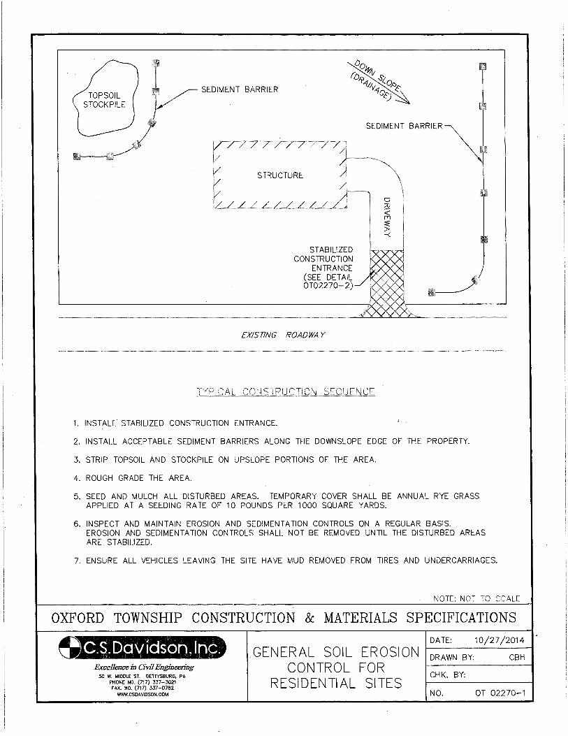
SEDIMENT BARRIER
SEDIMENT BARRIER
STRUCTURE
STABILIZED CONSTRUCTION
ENTRANCE (SEE DETAIL OT02270-2)
EXISTING ROADWAY
1. INSTALl STABILIZED CONSTRUCTION ENTRANCE.
2. INSTALL ACCEPTABLE SEDIMENT BARRIERS ALONG THE DOWNSLOPE EDGE OF THE PROPERTY.
3. STRIP TOPSOIL AND STOCKPILE ON UPSLOPE PORTIONS OF THE AREA.
4. ROUGH GRADE THE AREA.
5. SEED AND MULCH ALL DISTURBED AREAS. TEMPORARY COVER SHALL BE ANNUAL RYE GRASS APPLIED AT A SEEDING RATE OF 10 POUNDS PER 1000 SQUARE YARDS.
6. INSPECT AND MAINTAIN EROSION AND SEDIMENTATION CONTROLS ON A REGULAR BASIS. EROSION AND SEDIMENTATION CONTROLS SHALL NOT BE REMOVED UNTIL THE DISTURBED AREAS ARE STABILIZED.
7. ENSURE ALL VEHICLES LEAVING THE SITE HAVE MUD REMOVED FROM TIRES AND UNDERCARRIAGES.
NOTE: ~JOT TO SCALE
OXFORD TOWNSHIP CONSTRUCTION & MATERIALS SPECIFICATIONS
Excellence in Civil Engineering 50 W. MIDDLE ST. GETTiSBURG, PA
PHONE NO. (717) 337-3021 FAX. NO. (717) 337-0782
WWW.CSDAVIDSON.COM
GENERAL SOIL EROSION CONTROL FOR
RESIDENTIAL SITES
DATE: 10/27/2014
DRAWN BY: CBH
CHK. BY:
NO. OT 02270-1
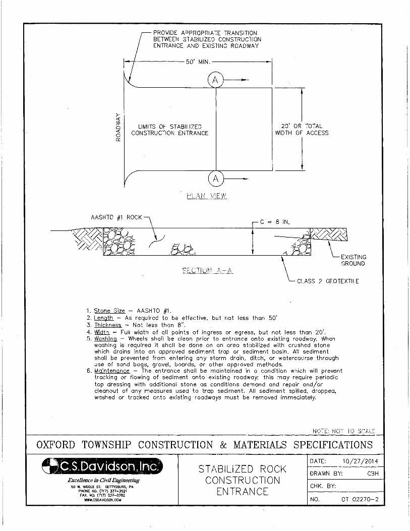
>-~ 0 <( 0 0::
AASHTO #1
PROVIDE APPROPRIATE TRANSITION BETWEEN STABILIZED CONSTRUCTION ENTRANCE AND EXISTING ROADWAY
LIMITS OF STABILIZED CONSTRUCTION ENTRANCE
I c
1. Stone Size - AASHTO #1.
20' OR TOTAL WIDTH OF ACCESS
8 IN,
\_ EXISTING GROUND
CLASS 2 GEOTEXTILE
2. Length - As required to be effective, but not less than 50' 3. Thickness - Not less than 8". 4. Width - Full width of all points of ingress or egress, but not less than 20'. 5. Washing - Wheels shall be clean prior to entrance onto existing roadway. When
washing is required it shall be done on an area stabilized with crushed stone which drains into an approved sediment trap or sediment basin. All sediment shall be prevented from entering any storm drain, ditch, or watercourse through use of sand bags, gravel, boards, or other approved methods.
6. Maintenance - The entrance shall be maintained in a condition which will prevent tracking or flowing of sediment onto existing roadway: this may require periodic top dressing with additional stone os conditions demand and repair and/or cleanout of any measures used to trap sediment. All sediment spilled, dropped, washed or tracked onto existing roadways must be removed immediately.
NOTE: NOT TO SCALE
OXFORD TOWNSHIP CONSTRUCTION & MATERIALS SPECIFICATIONS
u.~.Er>aviason, Inc. Excellence in Civil Engineering
50 W. MIDDLE ST. GETTYSBURG, PA PHONE NO. (717) 337-3021 FAX. NO. (717) 337-0782
WWW.CSOA \liD SON. COM
STABILIZED ROCK CONSTRUCTION
ENTRANCE
DATE: 10/27/2014
DRAWN BY: CBH
CHK. BY:
NO. OT 02270-2
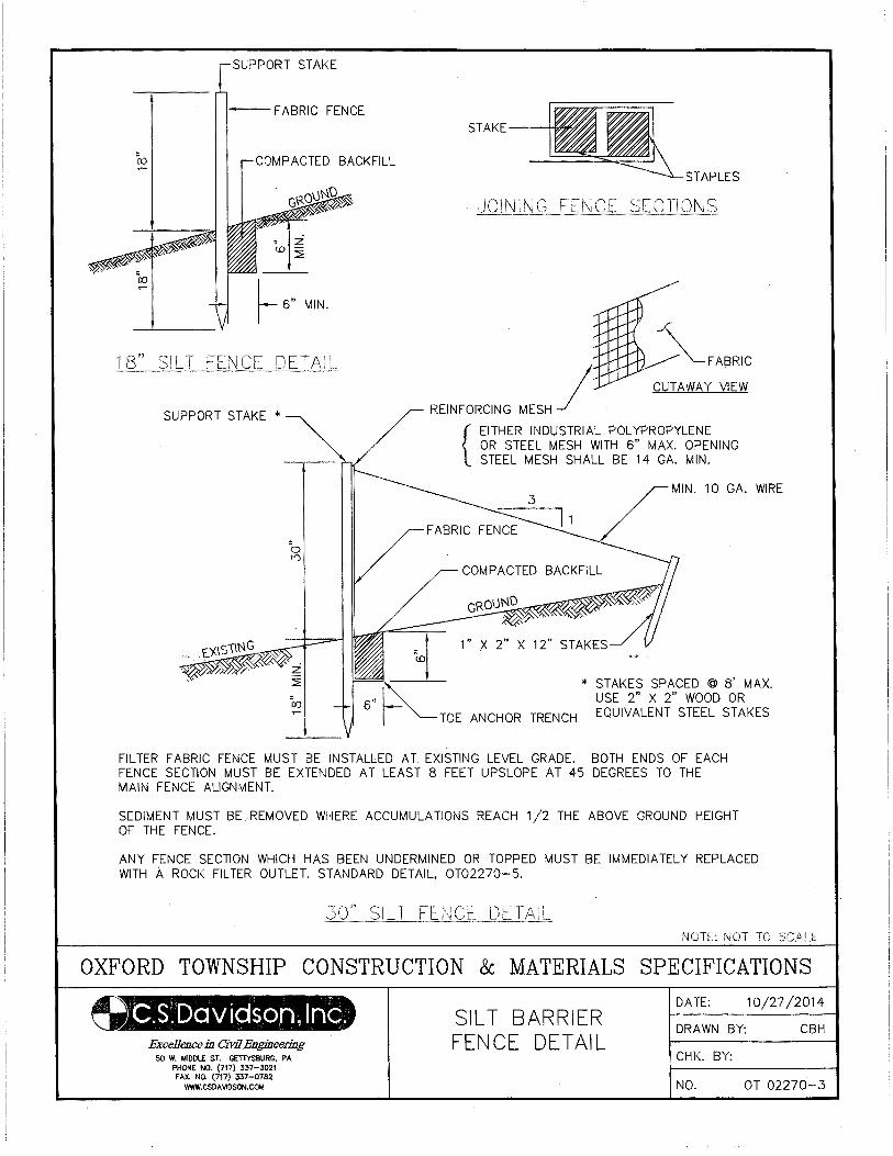
SUPPORT STAKE
I--FABRIC FENCE
COMPACTED BACKFILL
• z <.0 -
::2
SUPPORT STAKE *
STAPLES
REINFORCING MESH J CUTAWAY VIEW
{ EITHER INDUSTRIAL POLYPROPYLENE OR STEEL MESH WITH 6" MAX. OPENING STEEL MESH SHALL BE 14 GA. MIN.
TOE ANCHOR TRENCH
* STAKES SPACED @ 8' MAX. USE 2" X 2" WOOD OR EQUIVALENT STEEL STAKES
FILTER FABRIC FENCE MUST BE INSTALLED AT EXISTING LEVEL GRADE. BOTH ENDS OF EACH FENCE SECTION MUST BE EXTENDED AT LEAST 8 FEET UPSLOPE AT 45 DEGREES TO THE MAIN FENCE ALIGNMENT.
SEDIMENT MUST BLREMOVED WHERE ACCUMULATIONS REACH 1/2 THE ABOVE GROUND HEIGHT OF THE FENCE.
ANY FENCE SECTION WHICH HAS BEEN UNDERMINED OR TOPPED MUST BE IMMEDIATELY REPLACED WITH A ROCK FILTER OUTLET. STANDARD DETAIL, OT02270-5.
NOTE: NOT TO
OXFORD TOWNSHIP CONSTRUCTION & MATERIALS SPECIFICATIONS
~.s. Dav iasorn, In~. Excellence in Civil Engineering
50 W. MIDDLE ST. GETTYSBURG, PA PHONE NO. (717) 337-3021 FAX. NO. (717} 337-0782
WWW.CSDAVIDSON.COM
SILT BARRIER FENCE DETAIL
DATE: 10/27/2014
DRAWN BY: CBH
CHK. BY:
NO. OT 02270-3
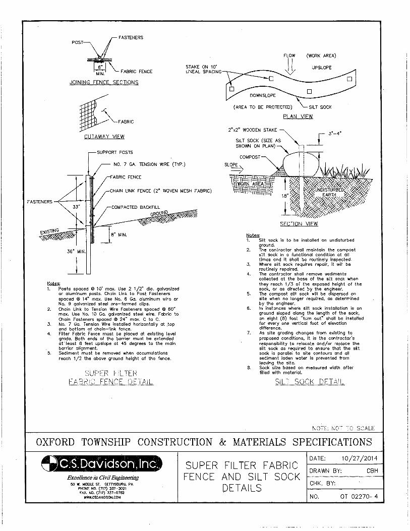
POST~ASlENERS
MIN. FABRIC FENCE
JOINING FENCE SECTIONS
CUTAWAY VIEW
NO. 7 GA. TENSION WIRE (TYP.)
FABRIC FENCE
STAKE ON 10' LINEAL SPACING
CHAIN LINK FENCE (2" WOVEN MESH FABRIC)
36" MIN.
_! MQW;; 1. Posts spaced @ 10' max. Use 2 1/2" dia. galvanized
or aluminum posts. Chain Link to Post Fasteners spaced @ 14" max. Use No. 6 Go. aluminum wire or No. 9 galvanized steel pre-formed clips.
2. Chain Link to Tension Wire Fasteners spaced @ 60" max. Use No. 10 Go. galvanized steel wire. Fabric to Chain Fasteners spaced @ 24" max. C to C.
3. No. 7 Ga. Tension Wire installed horizontally at top and bottom of chain-link fence.
4. Filter Fabric Fence must be placed at existing level grade. Both ends of the barrier must be extended at least 8 feet upslope at 45 degrees to the main barrier alignment.
5. Sediment must be removed when accumulations reach 1/2 the above ground height of the fence.
(WORK AREA)
UPSLOPE
(AREA TO BE PROTECTED)
PLAN VIEW
2"x2" WOODEN STAKE
SECTION VIEW
~ 1. Silt sock is to be installed on undisturbed
ground. 2. The contractor shall maintain the compost
silt sock in o functional condition at all times and it shall be routinely inspected.
3. Where silt sock requires repair, it will be routinely repaired.
4. The contractor shall remove sediments collected at the bose of the silt sock when they reach 1/3 of the exposed height of the sock, or as directed by the engineer.
5. The compost silt sock will be dispersed on site when no longer required, as determined by the engineer.
6. In instances where silt sock installation is an ground sloped along the length of the sock, on eight (8) foot "turn out" shall be installed for every one vertical foot of elevation difference.
7. As site grading changes from existing to proposed conditions, it is the contractor's responsibility to relocate and/or replace the silt sock as required to ensure that the silt sock is parallel to site contours and all sediment Ioden water is prevented from leaving the site.
8. Sock size based on measured width after filled with material.
NOTE: NOT TO SCALE
OXFORD TOWNSHIP CONSTRUCTION & MATERIALS SPECIFICATIONS
~.S.Daviasen, Inc. Excellence in Civil Engineering
50 W. MIDDLE ST. GETIYSBURG, PA PHONE NO. (717) 337-3021 FAX. NO. (717) 337-0782
WWW.CSDAVIOSON.COM
SUPER FENCE
FILTER FABRIC AND SILT SOCK DETAILS
DATE: 10/27/2014
DRAWN B~ CBH
CHK. BY:
NO. OT 02270-4
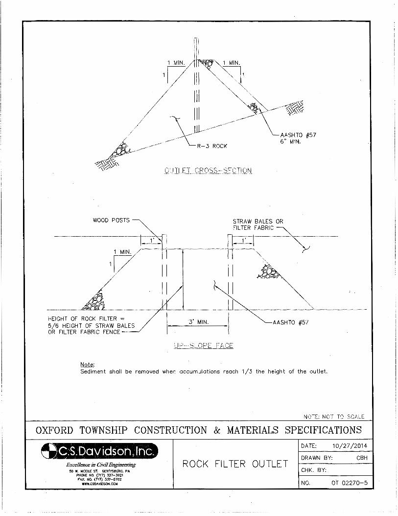
WOOD POSTS
HEIGHT OF ROCK FILTER = 5/6 HEIGHT OF STRAW BALES OR FILTER FABRIC FENCE
Note:
II II
1 MIN.
3' MIN.
AASHTO #57 6" MIN.
STRAW BALES OR FILTER FABRIC
AASHTO #57
Sediment shall be removed when accumulations reach 1/3 the height of the outlet.
NOTE: NOT TO SCALE
OXFORD TOWNSHIP CONSTRUCTION & MATERIALS SPECIFICATIONS
~.S.Da'Vidson,lnc. Excellence in Civil Engineering
50 W. MIDDLE ST. GETTYSBURG, PA PHONE NO. (717} 337-3021 FAX. NO. (717) 337-0782
WWW.CSDAVIDSON.COM
ROCK FILTER OUTLET
DATE: 10/27/2014
DRAWN BY: CBH
CHK. BY:
NO. OT 02270-5
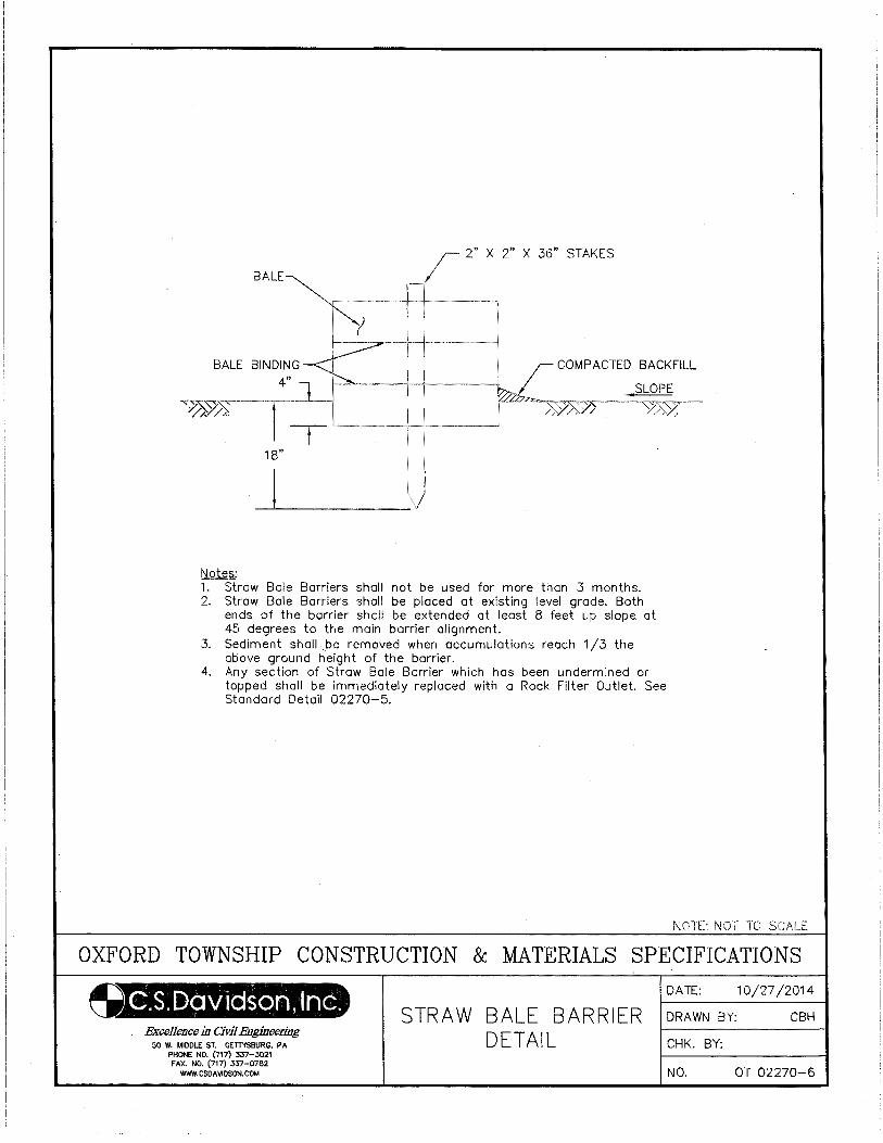
2" X 36" STAKES
BALE BINDING 4"
COMPACTED BACKFILL
v~~ -~.---l //, //.. t -t- '"'------+-+--·---·-J
18"
! Notes: 1. Straw Bale Barriers shall not be used for more than 3 months. 2. Straw Bale Barriers shall be placed at existing level grade. Both
ends of the barrier shall be extended at least 8 feet up slope at 45 degrees to the main barrier alignment.
3. Sediment shall _be removed when accumulations reach 1/3 the above ground height of the barrier.
4. Any section of Straw Bale Barrier which has been undermined or topped shall be immediately replaced with a Rock Filter Outlet. See Standard Detail 02270-5.
NOTE: NOT TO SCALE
OXFORD TOWNSHIP CONSTRUCTION & MATERIALS SPECIFICATIONS
Excellence in Civil Engineering 50 W. MIDDLE ST. GETTYSBURG, PA
PHONE NO. (717) 337-3021 FAX. NO. (717} 337-0782
WWW.CSDAVIOSON.COI.4
STRAW BALE BARRIER DETAIL
DATE: 10/27/2014
ORA WN BY: CBH
CHK. BY:
NO. OT 02270-6
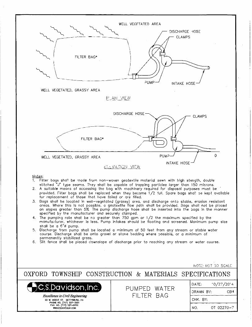
~ ~ ~ ~~WELL VEGETATED AREA DISCHARGE HOSE
FILTER BAG*
INTAKE HOSE}
WELL VEGETATED, GRASSY AREA
DISCHARGE HOSE
FILTER BAG*
WELL VEGETATED, GRASSY AREA 0
Notes: 1. Filter bogs shall be mode from non-woven geotextile material sewn with high stength, double
stitched "J" type seams. They shall be capable of trapping particles larger than 150 microns. 2. A suitable means of accessing the bog with machinery required for disposal purposes must be
provided. Filter bogs shall be replaced when they become 1/2 full. Spore bogs shall be kept available for replacement of those that hove failed or ore filled.
3. Bags shall be located in well-vegetated (grassy) area, and discharge onto stable, erosion resistant areas. Where this is not possible, a geotextile flow path shall be provided. Bogs shall not be placed on slopes greater than 5%. The pump discharge hose shall be inserted into the bags in the manner specified by the manufacturer and securely clamped.
4. The pumping rate shall be no greater than 750 gpm or 1/2 the maximum specified by the manufacturer, whichever is less. Pump intakes should be floating and screened. Maximum pump size shall be a 6"¢ pump.
5. Discharge from pump shall be located a minimum of 50 feet from any stream or stable water course. Discharge shall be onto gravel or stone bedding where possible, or a minimum of permanently stabilized grass.
6. Silt fence shall be placed downslope of discharge prior to reaching any stream or water course.
NOTE: NOT TO SCALE
OXFORD TOWNSHIP CONSTRUCTION & MATERIALS SPECIFICATIONS
0.S.Daviason, lnG. Excellence in Civil Engineering
50 W. MIDDLE ST. GEll'YSBURG, PA PHONE NO. (717) 337-3021 FAX. NO. (717) 337-0782
WWW.CSDAVIOSON.COM
PUMPED FILTER
WATER BAG
DATE: 10/27/2014
DRAWN BY: CBH
CHK. BY:
NO. OT 02270-7
02485-1
SECTION 02485
FINISH GRADING, SEEDING, AND SODDING
PART 1 GENERAL
1.01 DESCRIPTION
A. The work of this section includes, but is not limited to:
1. Placing topsoil
2. Soil conditioning
3. Finish grading
4. Seeding
5. Sodding
6. Mulching
7. Maintenance
B. Related work specified elsewhere:
1. Clearing and grubbing: Section 02100
2. Trenching, backfilling and compacting: Section 02221
C. Definitions: NONE
D. Applicable Standard Details: NONE
1.02 QUALITY ASSURANCE
A. Reference Standards:
1. Pennsylvania Department of Transportation (PennDOT), latest revision:
Publication 408, Specifications
2. American Association of State Highway Transportation Officials (AASHTO):
T194 Determination of Organic Matter in Soils by Wet Combustion
3. Pennsylvania Department of Agriculture
4. Others:
Agricultural Liming Materials Act of 1978, P.L.15
Pennsylvania Seed Act of 1965, Act 187, as amended
Pennsylvania Soil Conditioner and Plant Growth Substance Law, Act of December 1, 1977, P.L. 258
No. 86 (3P.S. 68.2) as amended
Rules for Testing Seeds of the Association of Official Seed Analysts
Federal and State pesticide acts and registration requirements
B. Sod Producer - Company specializing in sod production and harvesting with a minimum of 5 years
experience.
C. Sod Installer - Company specializing in performing this work with a minimum of 5 years experience.
02485-2
1.03 SUBMITTALS
A. Samples:
1. Unless otherwise directed, furnish three strips of sod, 4-1/2 feet long by 12" wide, laid on 3" of topsoil
and tamped in place. The samples shall be representative of the sod and workmanship to be provided.
Include sod source location.
B. Certificates:
1. Unless directed otherwise, prior to use or placement of material, submit certifications of material
composition of the following for approval:
a. Topsoil analysis
b. Fertilizer
c. Lime
d. Seed mixtures
e. Inoculant
f. Sod
1.04 JOB CONDITIONS - Section not utilized
PART 2 PRODUCTS
2.01 TOPSOIL
A. Having a pH of between 6.0 and 7.0; containing not less than 2% nor more than 10% organic matter as
determined by AASHTO T194.
B. Fertile friable loam, sand loam, or clay loam which will hold a ball when squeezed with the hand, but
which will crumble shortly after being released.
C. Free of clods, grass, roots, or other debris harmful to plant growth.
D. Free of pests, pest larvae, and matter toxic to plants.
2.02 FERTILIZER
A. Basic Dry Formulation Fertilizer:
1. Analysis 10-20-20 and as defined by the Pennsylvania Soil Conditioner and Plant Growth Substance
Law.
B. Starter Fertilizer:
1. Analysis 38-0-0 or 31-0-0 and as defined by the Pennsylvania Soil Conditioner and Plant Growth
Substance Law.
2.03 LIME
A. Raw ground limestone conforming to Publication 408, Section 804.2(a).
2.04 SEED
A. Deliver seed fully tagged and in separate packages according to species or seed mix. Seed which has
become wet, moldy, or otherwise damaged in transit or storage will not be accepted.

02485-3
B. Fresh, clean, dated material from the last available crop and within the date period specified, with a date of
test not more than 9 months prior to the date of sowing. Percentage of pure seed present shall represent
freedom from inert matter and from other seeds distinguishable by their appearance. All seeds will be
subject to analysis and testing.
TABLE 1 - GRASS AND AGRICULTURAL SEEDS
Species
Minimum
Guaranteed
Purity
(Percent)
Maximum
Weed
Seed
(Percent)
Minimum
Guaranteed
Germination
(Percent)
Kentucky Bluegrass (Poapratensis) 98 0.20 80
Perennial Ryegrass
(Loliumperenne, var. Pennfine)
98 0.15 90
Tall Fescue
(Festuca arundinacea),var. Kentucky 31)
98 0.15 85
Crownvetch
(Coronilla varia)
99 0.10 65
Creeping Red Fescue
(Festucarubra, var. Pennlawn)
98 0.15 85
Annual Rye Grass
(Loliummultiflorum)
98 0.15 90
Timothy (Phleum pratense) 98 0.25 85
2.05 SEED MIXTURES
A. See Seeding Restoration Table at end of this Section.
2.06 INOCULANT
A. Inoculate leguminous seed before seeding with nitrogen fixing bacteria culture prepared specifically for the
species.
B. Do not use inoculant later than the date indicated by the manufacturer.
C. Protect inoculated seed from prolonged exposure to sunlight prior to sowing.
D. Reinoculate seed not sown within 24 hours following initial inoculation.
2.07 MULCHING MATERIALS
A. Mulches for seeded areas shall be one, or a combination of, the following:
1. Straw:
c. Cured to less than 20% moisture content by weight.
d. Contain no stems of tobacco, soybeans, or other coarse or woody material.
e. Wheat or oat straw.
2. Wood Cellulose:
a. No growth or germination inhibiting substances.
b. Green, air dried. Packages not exceeding 100 pounds.
02485-4
c. Requirements:
Moisture Content: 12% ± 3%
Organic Matter: 98.6% ± 0.2% on the oven dried basis.
Ash Content: 1.4% ± 0.2%
Minimum Water-Holding Capacity: 1,000%
3. Mushroom Manure:
a. Organic origin, free of foreign material larger than 2" and substances toxic to plant growth.
b. Organic Matter: 20% minimum
c. Water-Holding Capacity: 120% minimum
d. pH: 6.0
B. Sewage sludge compost is not permitted.
2.08 SOD
A. Well-rooted Kentucky Bluegrass (Poa pratensis) sod containing a growth of not more than 10% of other
grasses and clovers.
B. Free from noxious weeds such as Bermuda grass, wild mustard, crab grass, and kindred grasses.
C. Mow sod in the field to a height of not more than 2-1/2" within 5 days prior to lifting.
D. Cut sod to a depth equal to the growth of the fibrous roots, but in no case less than 1-1/2", exclusive of grass
and thatch. Do not cut sod when the ground temperature is below 32F.
E. Deliver sod to the project site within 24 hours after being cut and place sod within 36 hours after being cut.
Do not deliver small, irregular, or broken pieces of sod. Do not deliver more sod than can be laid within 24
hours.
F. During wet weather, allow sod to dry sufficiently to prevent tearing during handling and placing. During
dry weather, moisten sod to ensure its vitality and to prevent dropping of the soil during handling. Sod
which dries out will be rejected.
PART 3 EXECUTION
3.01 TIME OF OPERATIONS
A. Spring Seeding:
1. Preliminary operations for seed bed preparation may commence as soon after February 15 as ground
conditions permit.
B. Fall Seeding:
1. Preliminary operations for seed bed preparation may commence after July 15.
3.02 FINISH GRADING
A. Preparation of Subgrade:
1. "Hard pan" or heavy shale:
02485-5
a. Plow to a minimum depth of 6".
b. Loosen and grade by harrowing, discing, or dragging.
c. Hand rake subgrade. Remove rocks over 2" in diameter and other debris.
2. Loose loam, sandy loam, or light clay:
a. Loosen and grade by harrowing, discing, or dragging.
b. Hand rake subgrade. Remove rocks over 2" in diameter and other debris.
B. Placing Topsoil:
1. Place topsoil and spread over the prepared subgrade to obtain the required depth and grade elevation.
Compact with a roller having not more than 65 pounds per roller foot width to a final compacted
thickness of not less than 4".
2. Hand rake topsoil and remove all materials unsuitable or harmful to plant growth.
3. Do not place topsoil when the subgrade is frozen, excessively wet, or extremely dry.
4. Do not handle topsoil when frozen or muddy.
C. Tillage:
1. After seed bed areas have been brought to proper compacted elevation, thoroughly loosen to a minimum
depth of 4" by discing, harrowing, or other approved methods. Do not work topsoiled areas when
frozen or excessively wet.
2. Liming:
a. Distribute lime uniformly at the specified rates.
b. Thoroughly incorporate into the topsoil to a depth of 4".
c. Incorporate as a part of the tillage operation.
3. Basic Fertilizer:
a. Distribute basic fertilizer uniformly at the specified rate.
b. Thoroughly incorporate into the topsoil to a depth of 4".
c. Incorporate as a part of tillage operation.
D. Finish Grading:
1. Remove unsuitable material larger than ½" in any dimension.
2. Uniformly grade surface to the required contours without the formation of water pockets.
3. Rework areas which puddle by the addition of topsoil and starter fertilizer and rerake.
3.03 SEEDING
A. Distribute starter fertilizer at the specified rates.
B. Incorporate starter fertilizer into the upper 1" of soil.
C. Uniformly sow specified seed mix by use of approved hydraulic seeder, power-drawn drill, power-operated
seeder, or hand-operated seeder. Do not seed when winds are over 15 mph.
02485-6
D. Upon completion of sowing, cover seed to an average depth of 1/4" by hand reraking or approved
mechanical methods.
E. Mulch immediately after seeding, using one of the following methods:
1. Place straw mulch in a continuous blanket at a minimum rate of 1,200 pounds per 1,000 square yards.
a. Anchor straw mulch by use of twine, stakes, wire staples, paper, or plastic nets.
b. Emulsified asphalt may be used for anchorage provided it is applied uniformly at a rate not less than
31 gallons per 1,000 square yards.
c. Chemical mulch binders may be used for anchorage if they are applied uniformly at the
manufacturer's recommended rate.
d. Chemical mulch binders or a light covering of topsoil may be used for anchorage when the size of
the area precludes the use of mechanical equipment.
2. Apply wood cellulose fiber hydraulically at a rate of 320 pounds per 1,000 square yards. Incorporate as
an integral part of the slurry after seed and soil supplements have been thoroughly mixed.
3. Spread mushroom manure uniformly to a minimum depth of ½" or to the depth indicated on the
drawings.
F. When mulch is applied to grass areas by blowing equipment, the use of cutters in the equipment will be
permitted to the extent that a minimum of 95% the mulch is 6" or more in length. For cut mulches applied
by the blowing method, achieve a loose depth in place of not less than 2".
G. When mulching by the asphalt mix method, apply the mulch by blowing. Spray the asphalt binder material
into the mulch as it leaves the blower. Apply the binder to the mulch in the proportion of 1.5 to 2.0 gallons
per 45 pounds of mulch.
1. Protect structures, pavements, curbs, and walls to prevent asphalt staining.
2. Erect warning signs and barricades at intervals of 50 feet or less along the perimeter of the mulched area.
3. Do not spray asphalt and chemical mulch binders onto any area within 100 feet of a stream or other body
of water.
3.04 SODDING
A. Prior to sod placement, complete finish grading and moisten prepared surface to received sod.
B. Do not place sod when the temperature is lower than 32F.
C. Place sod by hand with tight joints and no overlap. Transverse joints shall be broken or staggered.
D. Place sod so that the top of the sod is flush with the surrounding grade.
E. Use of tools which damage the sod or dumping of sod from vehicles will not be permitted.
F. Water sod to the saturation point immediately after placement.
G. After watering, tamp with an approved tamper to close all joints and insure close contact between sod and
sod bed. After tamping, the sod shall present a smooth, even surface free from bumps and depressions. If
so directed, use a light roller, weighing not more than 65 pounds per foot of roller width to complete firming
and smoothing the sod.
02485-7
H. When placing sod in ditches, place the strip with the long dimension at right angles to the flow of water. At
any point where water will start flowing over a sodded area, the upper edge of the sod strips shall be turned
into the soil below the adjacent area and a layer of compacted earth placed over this juncture to conduct the
water over the edge of the sod.
I. In ditches and on slope areas, stake each strip of sod securely with at least 1 wood stake for each 2 square feet
of sod. Stakes shall be ½" by 1" with a length of 8" to 12". Drive stakes flush with the top of the sod, with
the long face parallel to the slope contour.
3.05 MAINTENANCE
A. Maintenance includes watering, weeding, cleanup, edging and repair of depressions, washouts or gullies.
B. Those areas which do not show a prompt catch of grass within 14 days of seeding or sodding shall be
reseeded or resodded until complete grass catch occurs.
C. Maintain sodded areas for 3 months from date of substantial completion, mow to maintain maximum height
of 2-1/2" or as specified on drawings.
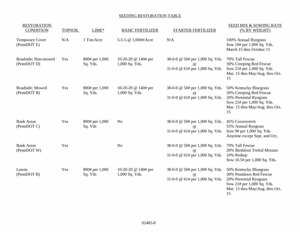
02485-8
SEEDING RESTORATION TABLE
RESTORATION
CONDITION TOPSOIL LIME* BASIC FERTILIZER STARTER FERTILIZER
SEED MIX & SOWING RATE
(% BY WEIGHT)
Temporary Cover
(PennDOT E)
N/A 1 Ton/Acre 5-5-5 @ 1,000#/Acre N/A 100% Annual Ryegrass
Sow 10# per 1,000 Sq. Yds.
March 15 thru October 15
Roadside; Non-mowed
(PennDOT D)
Yes 800# per 1,000
Sq. Yds.
10-20-20 @ 140# per
1,000 Sq. Yds.
38-0-0 @ 50# per 1,000 Sq. Yds.
or
31-0-0 @ 61# per 1,000 Sq. Yds.
70% Tall Fescue
30% Creeping Red Fescue
Sow 21# per 1,000 Sq. Yds.
Mar. 15 thru May/Aug. thru Oct.
15
Roadside; Mowed
(PennDOT B)
Yes 800# per 1,000
Sq. Yds.
10-20-20 @ 140# per
1,000 Sq. Yds.
38-0-0 @ 50# per 1,000 Sq. Yds.
or
31-0-0 @ 61# per 1,000 Sq. Yds.
50% Kentucky Bluegrass
30% Creeping Red Fescue
20% Perennial Ryegrass
Sow 21# per 1,000 Sq. Yds.
Mar. 15 thru May/Aug. thru Oct.
15
Bank Areas
(PennDOT C)
Yes 800# per 1,000
Sq. Yds
No 38-0-0 @ 50# per 1,000 Sq. Yds.
or
31-0-0 @ 61# per 1,000 Sq. Yds.
45% Crownvetch
55% Annual Ryegrass
Sow 9# per 1,000 Sq. Yds.
Anytime except Sept. and Oct.
Bank Areas
(PennDOT W)
Yes No 38-0-0 @ 50# per 1,000 Sq. Yds.
or
31-0-0 @ 61# per 1,000 Sq. Yds.
70% Tall Fescue
20% Birdsfoot Trefoil Mixture
10% Redtop
Sow 10.5# per 1,000 Sq. Yds.
Lawns
(PennDOT B)
Yes 800# per 1,000
Sq. Yds
10-20-20 @ 140# per
1,000 Sq. Yds.
38-0-0 @ 50# per 1,000 Sq. Yds.
or
31-0-0 @ 61# per 1,000 Sq. Yds.
50% Kentucky Bluegrass
30% Pennlawn Red Fescue
20% Perennial Ryegrass
Sow 21# per 1,000 Sq. Yds.
Mar. 15 thru May/Aug. thru Oct.
15
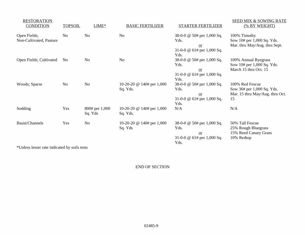
02485-9
RESTORATION
CONDITION TOPSOIL LIME* BASIC FERTILIZER STARTER FERTILIZER
SEED MIX & SOWING RATE
(% BY WEIGHT)
Open Fields;
Non-Cultivated, Pasture
No No No 38-0-0 @ 50# per 1,000 Sq.
Yds.
or
31-0-0 @ 61# per 1,000 Sq.
Yds.
100% Timothy
Sow 10# per 1,000 Sq. Yds.
Mar. thru May/Aug. thru Sept.
Open Fields; Cultivated No No No 38-0-0 @ 50# per 1,000 Sq.
Yds.
or
31-0-0 @ 61# per 1,000 Sq.
Yds.
100% Annual Ryegrass
Sow 10# per 1,000 Sq. Yds.
March 15 thru Oct. 15
Woods; Sparse No No 10-20-20 @ 140# per 1,000
Sq. Yds.
38-0-0 @ 50# per 1,000 Sq.
Yds.
or
31-0-0 @ 61# per 1,000 Sq.
Yds.
100% Red Fescue
Sow 36# per 1,000 Sq. Yds.
Mar. 15 thru May/Aug. thru Oct.
15
Sodding Yes 800# per 1,000
Sq. Yds
10-20-20 @ 140# per 1,000
Sq. Yds.
N/A N/A
Basin/Channels Yes No 10-20-20 @ 140# per 1,000
Sq. Yds
38-0-0 @ 50# per 1,000 Sq.
Yds.
or
31-0-0 @ 61# per 1,000 Sq.
Yds.
50% Tall Fescue
25% Rough Bluegrass
15% Reed Canary Grass
10% Redtop
*Unless lesser rate indicated by soils tests
END OF SECTION
02500-1
SECTION 02500
BITUMINOUS PAVING AND SURFACING
PART 1 GENERAL
1.01 DESCRIPTION
A. The work of this section includes, but is not limited to:
1. Superpave base course construction.
2. Placement and compaction of bituminous binder and wearing surface.
3. Placement of bituminous seal coat and surface treatment.
4. Surface preparation.
5. Pavement Markings.
B. Related work specified elsewhere:
1. Clearing and grubbing: Section 02100
2. Site excavation and placement of fill material: Section 02210
3. Roadway excavation, fill, and compaction: Section 02230
4. Pavement markings Section 02760
C. Definitions: NONE
D. Applicable Standard Details:
OT 02500-1 Typical Street Cross Section
OT 02500-1A Local Street Cross Section (Standard)
OT 02500-2 Street Widening Detail
OT 02500-2A Local Street Cross Section (Alternate)
OT 02500-3 Roadway Sign Details
OT 02500-3A Collector and Arterial Street Cross Section (Standard)
OT 02500-4 Local Street (Without Curbs) Cross Section
OT 02500-4A Collector and Arterial Street Cross Section (Alternate)
OT 02500-5 Residential Driveway Profile (Curbed Street)
OT 02500-5A Industrial Street Cross Section (Standard)
OT 02500-6 Residential Driveway Profile (No Curbs)
OT 02500-6A Industrial Street Cross Section (Alternative)
1.02 QUALITY ASSURANCE
A. Reference Standards:
1. Pennsylvania Department of Transportation (PennDOT), latest revision:
Publication 408, Specifications
Publication 213, Work Zone Traffic Control Guidelines
Publication 27, Specification for Bituminous Mixtures (Bulletin 27)
Publication 37, Specification for Bituminous Materials (Bulletin 25)
Publication 68, Regulations - Traffic Signs, Signals and Markings
Publication 236M, Handbook of Approved Signs
2. American Society for Testing and Materials (ASTM):
02500-2
D2950 Test Method for Density of Bituminous Concrete in Place by Nuclear Methods
3. Pennsylvania Code
Title 67. Transportation, Chapter 459, Occupancy of Highways by Utilities
B. Inspections:
1. Inspection by the Municipality will, at a minimum, be made of the subgrade prior to placement of the
base course, and of the base course prior to placement of the binder surface.
C. Qualifications:
1. Pavement marking contractor shall have at least five years documented experience specializing in
installing pavement markings.
1.03 SUBMITTALS
A. Certification:
1. Job Mix Formula - Submit job mix formula to the owners engineer five (5) days prior to start of work.
2. Provide PennDOT Certification of Compliance (CS-4171) with the first load delivered to the job site
each day. Certification must be signed by the plant technician and cross referenced with the job mix
formula number which must appear on the delivery ticket.
3. Delivery Tickets/Weight Slips - Must be provided with each load delivered to the job site. Weight slips
must include, at a minimum, the following:
a. Job Mix Formula Number
b. Date and Time
c. Material Type
d. Design ESALS
e. For Wearing Course - SRL Designation
4. Provide compaction testing results.
1.04 JOB CONDITIONS
A. Control Traffic:
1. Take measures to control traffic during paving operations. Do not allow traffic on newly paved areas
until adequate stability and adhesion have been attained and the material has cooled to 140 F or less.
2. Employ traffic control measures in accordance with Publication 213.
3. Notify all appropriate emergency services (police, fire and ambulance) a minimum of 36 hours in
advance of any temporary lane closures.
B. Protection of Adjacent Areas:
1. Restore existing surface outside the limits of the work that has been damaged by the CONTRACTOR’s
operations, to its original condition at the expense of the CONTRACTOR.
2. Reasonable access must be maintained for adjacent property owners and commercial properties.
02500-3
PART 2 PRODUCTS
2.01 BITUMINOUS MATERIALS AND AGGREGATES
A. All bituminous materials and aggregates used in base course construction, paving, and resurfacing are
designated in these specifications by, and shall conform to, the applicable portions of the Publication 408
Specifications. The coarse aggregate used in bituminous wearing surfaces shall have the following
aggregate Skid Resistance Level (SRL) letter designation based on the current Average Daily Traffic (ADT)
for resurfacing or anticipated initial daily traffic on new facilities:
ADT SRL ALTERNATIVES
20,000 and Above E None
5,000 to 20,000 H E, H, Blend of E and M,
Blend of E and G
3,000 to 5,000 G E, H, G, Blend of H and M,
Blend of E and L
1,000 to 3,000 M E, H, G, M, Blend of H and L,
Blend of G and L,
Blend of E and L
1,000 and Below L Any
Note: All blends are 50% by mass and shall be accomplished by an approved method.
B. All Superpave (HMA) mixtures shall conform to applicable portions of Publication 408 Specifications.
Aggregate shall be provided by approved sources and have the SRL designation as specified above. All
mixtures will be petroleum grade PG 64-22 and 0 to 0.3 million ESAL’s unless specified otherwise by the
Municipality. Aggregate size is shown on Standard Details.
2.02 SIGNS
A. Post mounted signs shall be on breakaway 2" square steel posts with CAPS as per PennDOT Publication
408, Sections 931 and 1103.
B. Signs shall conform to PennDOT Publication 236M. Street name signs shall be single sided. Street signs
shall be located on the opposite side of the intersection from the stop signs. Street signs shall be mounted on
a post (conforming with Section 2.02.A above) without any other signage.
PART 3 EXECUTION
3.01 BASE COURSES
A. Superpave Asphalt HMA Base Course - Where indicated on the drawings, construct HMA base course to
compacted depth in accordance with Publication 408, Section 309. Proof roll base course to satisfaction of
the Municipality. Municipality shall approve crushed aggregate base course prior to placement of base
course.
02500-4
B. Bituminous Concrete – Where indicated on the Contract Drawings and/or shown in the “Backfill and
Surface Restoration Requirements Table,” construct bituminous concrete base course to compacted depth in
accordance with Publication 408 Specifications, Section 305. Proof roll base course to satisfaction of the
ENGINEER. ENGINEER shall approve crushed aggregate base course prior to placement of Bituminous
Concrete base course.
C. Bituminous paver shall be self-propelled with activated screed and shall have a minimum paving width of
18’. All exceptions must be approved by the OWNER and ENGINEER.
3.02 PREPARATION OF EXISTING PAVEMENT SURFACE
A. Clean street surface of all dust, debris, loose stone, earth, or other deleterious material by means of hand
brooms or approved power brooms.
B. Scarify areas shown on the drawings. Where the existing base is judged inadequate by the Municipality,
construct new base of the required type shown on Standard Detail 02500-1.
C Seal all cracks in accordance with Publication 408, Specification 469 with ENGINEER approval, cracks
may be filled with PG 64-22.
D. Patch holes and depressions greater than one inch and less than four inches with Superpave (19mm) binder
material, compacted in layers not exceeding two inches after compaction.
E. Holes greater than four inches in depth shall be sawed back to sound pavement, and patched with a minimum
of eight (8) inches of crushed aggregate base course and a depth of Superpave (19mm) binder material that
matches the depth of existing pavement The minimum depth of binder material shall be two inches.
F. Apply tack coat prior to overlaying existing pavement in accordance with Publication 408 Specifications,
Section 460.
G. Milling of existing bituminous pavement shall be performed in accordance with Publication 408, Section
491 to the depth and limits specified in the drawings.
1. Saw cut all edges at intersections with streets and driveways and at the limits of work.
2. Millings must be disposed of properly. Remove all loose material left behind the milling machine.
3. Supply all water as needed.
4. CONTRACTOR shall provide transitions from milled surfaces to non-milled surfaces to allow vehicular
traffic during non-working hours.
H. Construct scratch or leveling courses as directed by the ENGINEER.
I. Proof roll subgrade before base course placement. If precipitation occurs, then subgrade must be proof
rolled again prior to bituminous material placement.
3.03 SURFACE COURSES
A. Superpave Asphalt
1. HMA Binder Course - Construct HMA binder course with aggregate size, Design ESAL’s and PG
specified and to the compacted depth shown on the Contract Drawings, in accordance with Publication
408 Specifications, Section 409.
2. HMA Wearing Course - Construct HMA wearing course with aggregate size, Design ESAL’s and PG
specified and to the compacted depth shown on the Contract Drawings, in accordance with Publication
408 Specifications, Section 409.
02500-5
3. Tack coat shall be applied to ensure bonding between courses and shall conform to Publication 408
Specifications, Section 460.
4. Compaction testing for in-place density shall be conducted during placement of the material, in
accordance with PennDOT Publication 408, Section 409. Alternatively, pavement cores, in accordance
with Section 409.4, may be substituted. Acceptable density shall be within 90-97% of the maximum
theoretical density, as per ASTM D698.
5. Do not allow vehicular traffic on newly compacted Superpave HMA materials until the temperature
cools below 140˚F.
6. Bituminous paver shall be self-propelled with activated screed and shall have a minimum paving width
of 18’. All exceptions to paver requirement shall be approved by the OWNER and ENGINEER.
B. Bituminous Surface Course (ID-2)
1. Construct binder course meeting the requirements of Publication 408 Specifications, Section 421 to
compacted depth specified in the "Backfill and Surface Restoration Requirements Table".
2. Construct wearing surface meeting the requirements of Publication 408 Specifications, Section 420 to
the compacted depth specified in the "Backfill and Surface Restoration Requirements Table".
3. Do not allow vehicular traffic on newly compacted bituminous material until the temperature cools
below 140˚F.
4. Bituminous paver shall be self-propelled with activated screed and shall have minimum paving width of
18’. All exceptions to paver requirements shall be approved by the OWNER or ENGINEER.
C. Compaction
1. Compact by rolling with steel-wheel, vibration or pneumatic tire rollers or a combination of these to
obtain specified layer thickness and until non-movement of material under compaction equipment is
achieved, unless other density requirements are specified in Section VIII - Technical Provisions
(Detailed).
2. The roller pattern and speed shall be monitored by the CONTRACTOR and ENGINEER to avoid roller
marks, pattern segregation and displacement of hot mixtures.
D. Bituminous Seal Coat (single application)
1. Construct bituminous seal coat in accordance with Publication 408 Specifications, Section 470.
E. Bituminous Surface Treatment (double application)
1. Construct bituminous surface treatment in accordance with Publication 408 Specifications, Section 480.
3.04 JOINTS
A. Notch
The edge of an overlay shall be saw cut to a depth of 1-1/2" for the entire length of the joint and the detached
material removed to a minimum notch width of 12". Notch shall be skewed a minimum 6:1 unless
otherwise noted. A cold planer may be used. The vertical face must be painted with PG64-22 or the same
asphalt material used in mix design (Publication 408, Section 401.3(j)).
02500-6
B. Sealing
All joints shall be sealed rubberized joint sealing material. When wearing course is placed adjacent to curb
to form bituminous gutter, seal with hot bituminous material of the class and type designated for wearing
course and extend to 6 inches from the curb, applied evenly. The use of PG 64-22 may be permitted when
approval is obtained from the ENGINEER.
3.05 SIGNS
A. Install signs at locations shown on drawings or otherwise specified by Municipality.
B. Posts shall be installed in undisturbed earth with anchor top 4" above ground on lower slope side.
C. Where posts are located in concrete, drill the existing concrete to place anchor. If in new concrete, place
PVC sleeve in concrete prior to placing post.
3.06 FIELD QUALITY CONTROL
A. Proof of Product
At the time of material delivery to the site, the TOWNSHIP’s Representative or ENGINEER shall be
furnished with a delivery ticket indicating material specifications. The tickets shall include, but not limited
to, vehicle identification, date, time, product identification, product quantity (Petroleum Grade, Equivalent
Single, Axle Loading (ESAL’s), aggregate size and Skid Resistance Level (SRL) (for bituminous wearing
course).
B. Surface Tolerance of Base and Binder Course.
After the base course has been completed as specified, the surface smoothness shall be checked with
approved templates, string lines, or straightedges.
1. Templates. The CONTRACTOR shall furnish and use approved templates of required length and cut
to the required crown of the finished surface of the base course, for checking the crown and contour
thereof. The templates shall be equipped with metal or other approved vertical extensions attached to
each end, so that the bottom of the template will be at the elevation of the top of the aggregate. At least
3 such templates shall be furnished, and used at intervals of not more than 25 feet.
2. String Lines. String lines, for controlling the finished elevation of the base course, shall be furnished
with ample supports and offset along each side of the base course, and shall be maintained until all
irregularities have been satisfactorily corrected.
3. Straightedges. Approved straightedges 10 feet in length shall also be furnished and used for testing
longitudinal irregularities in the surface of the base course.
Any surface irregularities that exceed ½ inch shall be remedied by removing or adding bituminous
material as required, after which the entire area, including the surrounding surface, shall be rolled until
satisfactorily compacted.
B. Tests for Depth of Finished Base Course.
During the progress of the work, the depth of the base course will be measured by the Municipality and
unsatisfactory work shall be repaired, corrected, or replaced. The Municipality will not be liable for
payment for any excess depth of base course.
02500-7
1. The depth will be determined by cutting or coring holes to the full depth of the completed base course.
One depth measurement may be required for each 1500 square yards, or less, of completed base course.
Any section in which the depth is ½ inch or more deficient in specified depth, shall be satisfactorily
corrected at no expense to the Municipality.
2. All test holes shall be backfilled with similar material and satisfactorily compacted by and at the expense
of the Contractor. This operation shall be performed under the observation of the Municipality who
will check the depth for record purposes.
C. Surface Tolerance of Wearing Course.
After the wearing course has been completed as specified, the surface smoothness shall be checked with
straightedges.
1. Straightedges. Approved straightedges 10 feet in length shall be furnished and used for testing
longitudinal irregularities in the surface of the wearing course.
Any surface irregularities that exceed 3/16 inch shall be remedied by removing or adding wearing
material as required, after which the entire area, including the surrounding surface, shall be rolled until
satisfactorily compacted.
D. Tests for Depth of Finished Wearing Course.
During the progress of the work, the depth of the wearing course may be measured by the Municipality and
unsatisfactory work shall be repaired, corrected, or replaced. The Municipality will not be liable for
payment for any excess depth of wearing course.
1. The depth will be determined by cutting or coring holes to the full depth of the completed wearing
course. Test holes to be excavated by the Contractor at no expense to the Municipality. One depth
measurement may be required for each 1500 square yards of completed wearing course. Any section in
which the depth is 1/4 inch or more deficient in specified depth, shall be satisfactorily corrected at no
expense to the Municipality.
2. All test holes shall be backfilled with similar material and satisfactorily compacted by and at the expense
of the Contractor. This operation shall be performed under the observation of the Municipality who
will check the depth for record purposes.
END OF SECTION
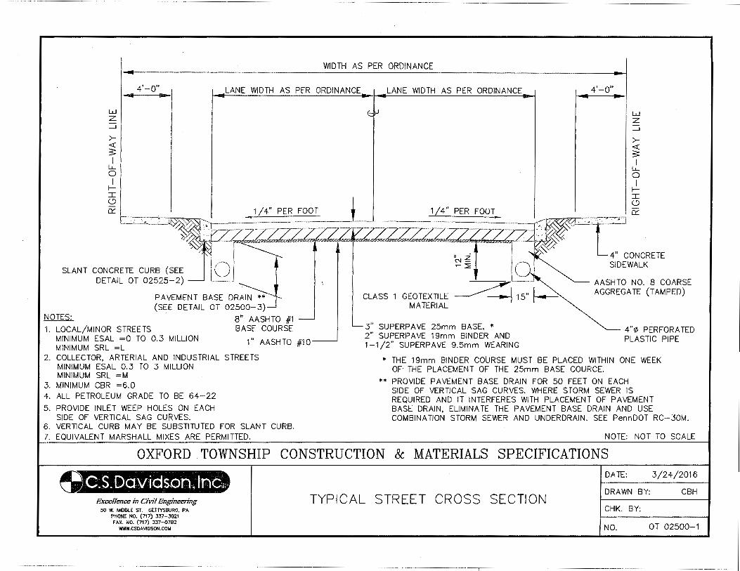
4'-o" LANE WIDTH AS PER ORDINANCE LANE WIDTH AS PER ORDINANCE 4'-0"
w z _J
><(
3 I
u... 0 I
II C)
SLANT CONCRETE CURB (SEE DETAIL OT 02525-2)
1 I 4_"_£>ER
PAVEMENT BASE DRAIN (SEE DETAIL OT 02500-3)
NOTES:
1. LOCAL/MINOR STREETS MINIMUM ESAL =0 TO 0.3 MILLION MINIMUM SRL =L
8" AASHTO #1 BASE COURSE
1" AASHTO #1 0
2. COLLECTOR, ARTERIAL AND INDUSTRIAL STREETS MINIMUM ESAL 0.3 TO 3 MILLION MINIMUM SRL =M
3. MINIMUM CBR =6.0 4. ALL PETROLEUM GRADE TO BE 64-22
5. PROVIDE INLET WEEP HOLES ON EACH SIDE OF VERTICAL SAG CURVES.
6. VERTICAL CURB MAY BE SUBSTITUTED FOR SLANT CURB. 7. EQUIVALENT MARSHALL MIXES ARE PERMITTED.
w z _J
><(
3 I
u... 0 I
II
1 I~ l 1/4" PER FOOT_ - ~[--::_~~:::2] t ---J --~~ --- --~--- ~-~·-.. ~~"« 4" CONCRETE
- ~--~ ~~ "--- I 'X' SIDEWALK
- Z 1- COARSE
\:';, I~ AASHTGOA~~·(*AMPED) CLASS 1 GEOTEXTILE
MATERIAL
3" SUPERP AVE 25mm BASE, * 2" SUPERP AVE 19mm BINDER AND 1-1/2" SUPERPAVE 9.5mm WEARING
AGGRE
4"11\ PERFORATED PLASTIC PIPE
* THE 19mm BINDER COURSE MUST BE PLACED WITHIN ONE WEEK OF THE PLACEMENT OF THE 25mm BASE COURCE.
** PROVIDE PAVEMENT BASE DRAIN FOR 50 FEET ON EACH SIDE OF VERTICAL SAG CURVES. WHERE STORM SEWER IS REQUIRED AND IT INTERFERES WITH PLACEMENT OF PAVEMENT BASE DRAIN, ELIMINATE THE PAVEMENT BASE DRAIN AND USE COMBINATION STORM SEWER AND UNDERDRAIN. SEE PennDOT RC-30M.
NOTE: NOT TO SCALE
OXFORD TOWNSHIP CONSTRUCTION & MATERIALS SPECIFICATIONS
Exc:cUcncc in Civil Engineering 50 W. MIDDLE ST. GETTYSBURG, PA
PHONE NO. (717) 337-3021 FAX. NO. (717) 337-0782
WWW.CSDAIIIDSON.COM
TYPICAL STREET CROSS SECTION
DATE: 3/24/2016
DRAWN BY: CBH
CHK. BY:
NO. OT 02500-1
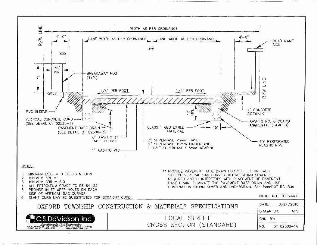
------- -- I
LU z _J ~.-------------------------------------------------------------------------------------------------~
5 ........ a::
4'-0"
SIGN
LANE WIDTH AS PER ORDINANCE
_...----t- BREAKAWAY POST (TYP.)
LANE WIDTH AS PER ORDINANCE 4'-0"
LU z _J
ROAD NAME SIGN
VERTICAL CONCRETE CURB (SEE DETAIL CT 02525-1)
1/4" PER FOOT :.'l<~~+;:~-~:rll ~
~ ~~:ai~~c;m: -~ ~ AASHTO NO.8 COARSE
PAVEMENT BASE DRAIN ** (SEE DETAIL OT 02500-3)
8" AASHTO #1 BASE COURSE
1" AASHTO #1 0 ----'
NOTES:
1. MINIMUM ESAL = 0 TO 0.3 MILLION 2. MINIMUM SRL = L 3. MINIMUM CBR = 6.0 4. ALL PETROLEUM GRADE TO BE 64-22 5. PROVIDE INLET WEEP HOLES ON EACH
SIDE OF VERTICAL SAG CURVES. 6. SLANT CURB MAY BE SUBSTITUTED FOR STRAIGHT CURB.
CLASS 1 GEOTEXTILE _____.......... ----tiiOo--115" I~ AGGREGATE (TAMP ED)
MATERIAL
3" SUPERPAVE 25mm BASE, 2" SUPERPAVE 19mm BINDER AND 1-1/2" SUPERPAVE 9.5mm WEARING
4"~ PERFORATED PLASTIC PIPE
** PROVIDE PAVEMENT BASE DRAIN FOR 50 FEET ON EACH SIDE OF VERTICAL SAG CURVES. WHERE STORM SEWER IS REQUIRED AND IT INTERFERES WITH PLACEMENT OF PAVEMENT BASE DRAIN, ELIMINATE THE PAVEMENT BASE DRAIN AND USE COMBINATION STORM SEWER AND UNDERDRAIN. SEE PennDOT RC-30M.
NOTE: NOT TO SCALE
OXFORD TOWNSHIP CONSTRUCTION & MATERIALS SPECIFICATIONS DATE: 3/24/2016
DRAWN BY: APS
LOCAL STREET CHK. BY:
CROSS SECJION (STANDARD) NO. OT 02500-1A
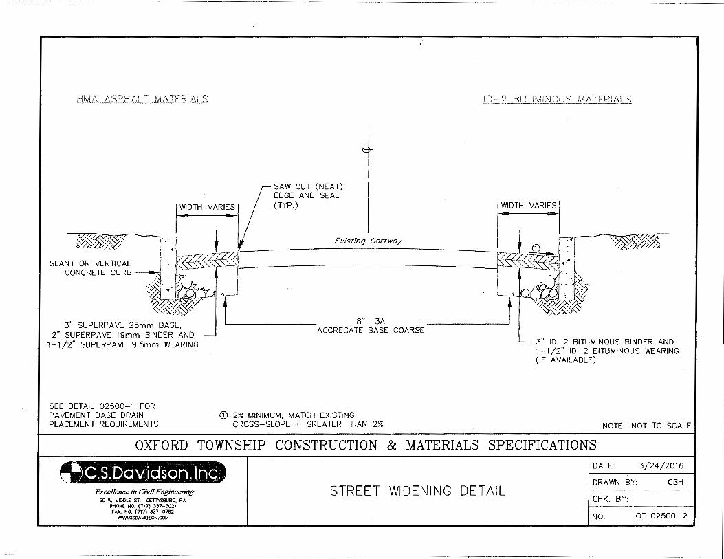
+ WIDTH VARIES
SAW CUT (NEAT) EDGE AND SEAL (TYP.) WIDTH VARIES
SEE DETAIL 02500-1 FOR PAVEMENT BASE DRAIN PLACEMENT REQUIREMENTS
8" 3A . AGGREGATE BASE COARSE---------'
(j) 2% MINIMUM, MATCH EXISTING CROSS-SLOPE IF GREATER THAN 2%
3" ID-2 BITUMINOUS BINDER AND 1-1/2" ID-2 BITUMINOUS WEARING (IF AVAILABLE)
NOTE: NOT TO SCALE
OXFORD TOWNSHIP CONSTRUCTION & MATERIALS SPECIFICATIONS
ExceUcncc in Civil Engineering 50 W. MIDDLE ST. GETTYSBURG, PA
PHONE NO. (717) 337-3021 FAX. NO. (717) 337-0782
WWW.CSOA\IIOSON.COM
STREET WIDENING DETAIL
DATE: 3/24/2016
ORA WN BY: CBH
CHK. BY:
NO. OT 02500-2
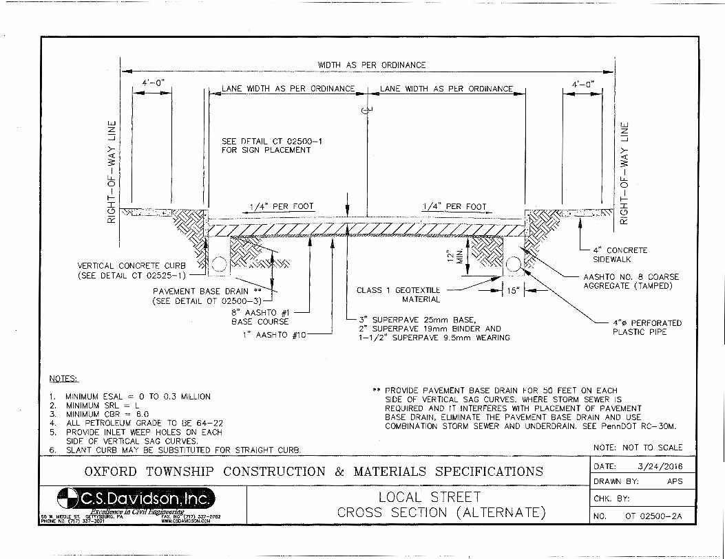
WIDTH AS PER ORDINANCE
w z _j
><(
$ I
LL. 0
LANE WIDTH AS PER ORDINANCE
SEE DETAIL CT 02500-1 FOR SIGN PLACEMENT
I fI c.? ~~~ .. -. -. -.. ,.,...../7.'77":; 0:::
PAVEMENT BASE DRAIN (SEE DETAIL OT 02500-3)
NOTES:
1. MINIMUM ESAL = 0 TO 0.3 MILLION 2. MINIMUM SRL = L 3. MINIMUM CBR = 6.0 4. ALL PETROLEUM GRADE TO BE 64-22 5. PROVIDE INLET WEEP HOLES ON EACH
SIDE OF VERTICAL SAG CURVES.
8" AASHTO #1 BASE COURSE
1'' AASHTO #10
6. SLANT CURB MAY BE SUBSTITUTED FOR STRAIGHT CURB.
LANE WIDTH AS PER ORDINANCE
CLASS 1 GEOTEXTILE MATERIAL
3" SUPERP AVE 25mm BASE, 2" SUPERPAVE 19mm BINDER AND 1-1/2" SUPERPAVE 9.5mm WEARING
4'-0"
w z _j
><(
3 I
LL. 0 I
fI =' . .· ·· ·x<::<::l 0
AASHTO NO. 8 COARSE AGGREGATE (TAMPED)
4"¢ PERF ORA TED PLASTIC PIPE
** PROVIDE PAVEMENT BASE DRAIN FOR 50 FEET ON EACH SIDE OF VERTICAL SAG CURVES. WHERE STORM SEWER IS REQUIRED AND IT INTERFERES WITH PLACEMENT OF PAVEMENT BASE DRAIN, ELIMINATE THE PAVEMENT BASE DRAIN AND USE COMBINATION STORM SEWER AND UNDERDRAIN. SEE PennDOT RC-30M.
NOTE: NOT TO SCALE
OXFORD TOWNSHIP CONSTRUCTION & MATERIALS SPECIFICATIONS DATE: 3/24/2016
DRAWN BY: APS
LOCAL STREET CHK. BY:
CROSS SECTION (ALTERNATE) NO. OT 02500-2A
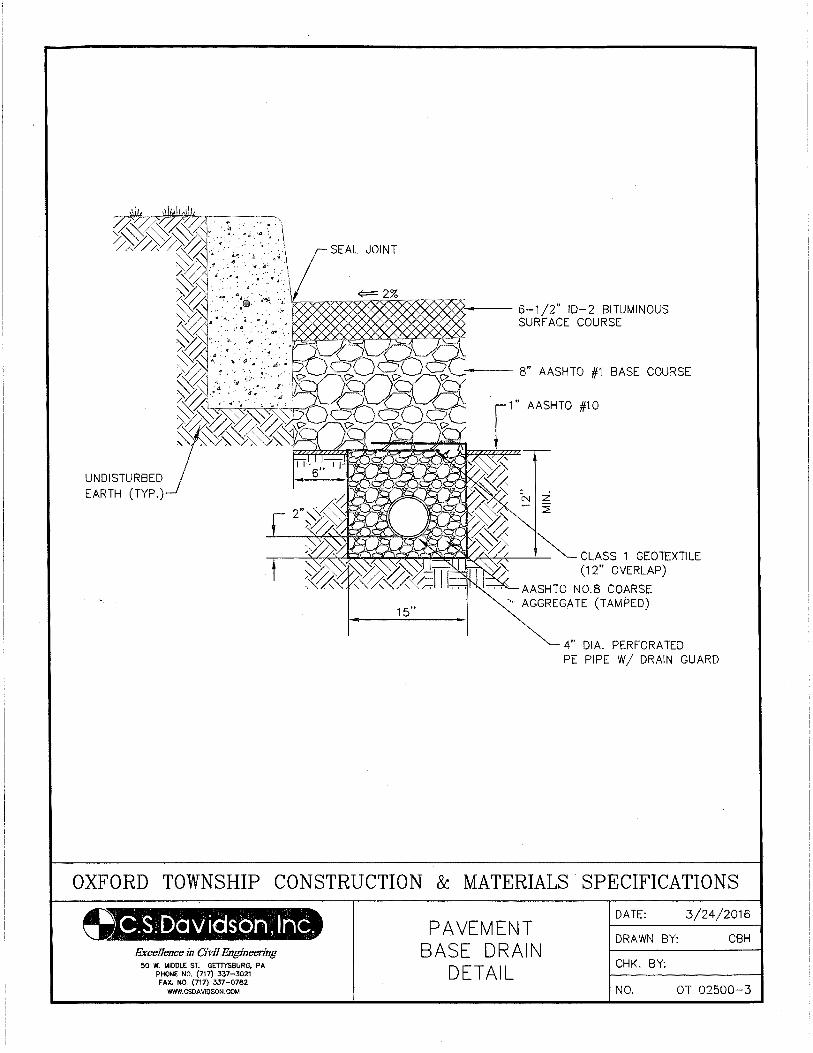
-- 8" AASHTO #1 BASE COURSE
1" AASHTO #1 0
CLASS 1 GEOTEXTILE (12" OVERLAP)
' AASHTO N0.8 COARSE AGGREGATE (TAMPED)
4" DIA. PERFORATED PE PIPE W/ DRAIN GUARD
OXFORD TOWNSHIP CONSTRUCTION & MATERIALS SPECIFICATIONS
ExceUence in Civil Engineering 50 W. MIDDLE ST. GETTYSBURG, PA
PHONE NO. (717) 337-3021 FAX. NO. (717} 337-0782
WWW.CSDAVIOSON.COM
PAVEMENT BASE DRAIN
DETAIL
DATE: 3/24/2016
DRAWN BY: CBH
CHK. BY:
NO. OT 02500-3
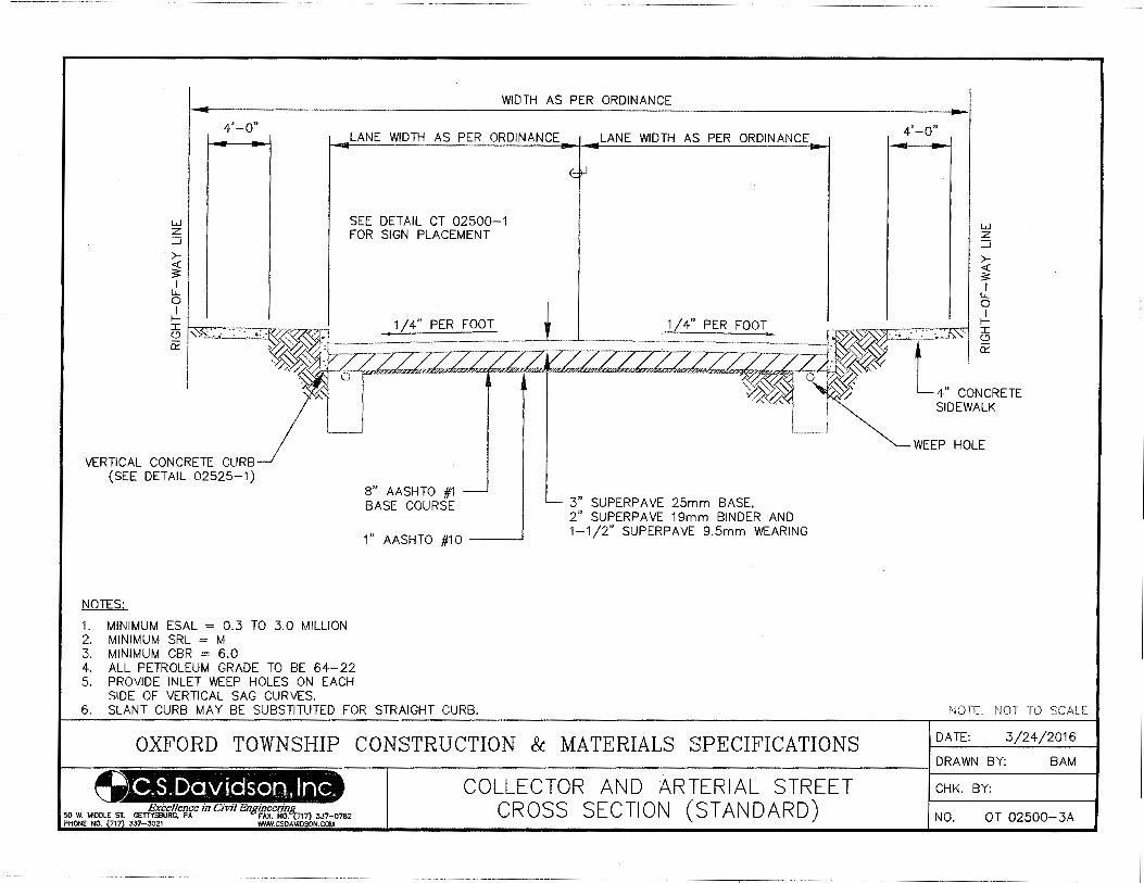
WIDTH AS PER ORDINANCE
w z ::J
>-~ I u..
4'-o" LANE WIDTH AS PER ORDINANCE
SEE DETAIL CT 02500-1 FOR SIGN PLACEMENT
LANE WIDTH AS PER ORDINANCE
Y . , ' 1/4" PER FOOT f [ ~·-"_P_E_R __ Fo_o_T ------;.-r-<, ~ !,>~~·:.·~~~~-~- · ~- ·-:: zzz/zzzz·· · ~ ~~~: z .. -~-T7Z.77 r-r2·~z-L~. ~-,-.. ,:.--r~~E..-:>·...,,,.,....,.,, . .,, •. ,.,.,.,..~"'=lr .... · , .. ~~·""""w~·.,,~~mT.L v/;y ~ 0-""f~.'*~,.,L~"""~ .. r·~ 1 1
"''l
VERTICAL CONCRETE CURB (SEE DETAIL 02525-1)
NOTES:
i I ~~~
1. MINIMUM ESAL = 0.3 TO 3.0 MILLION 2. MINIMUM SRL = M 3. MINIMUM CBR = 6.0 4. ALL PETROLEUM GRADE TO BE 64-22 5. PROVIDE INLET WEEP HOLES ON EACH
SIDE OF VERTICAL SAG CURVES.
8" AASHTO #1 BASE COURSE
1" AASHTO #10 __ __,
3" SUPERPAVE 25mm BASE, 2" SUPERP AVE 19mm BINDER AND 1-1/2" SUPERPAVE 9.5mm WEARING
6. SLANT CURB MAY BE SUBSTITUTED FOR STRAIGHT CURB.
OXFORD TOWNSHIP CONSTRUCTION & MATERIALS SPECIFICATIONS
COLLECTOR AND ARTERIAL STREET CROSS SECTION (STANDARD)
4'-o"
w z ::J
WEEP HOLE
NOTE: NOT TO SCALE
DATE: 3/24/2016
DRAWN BY: BAM
CHK. BY:
NO. OT 02500-3A
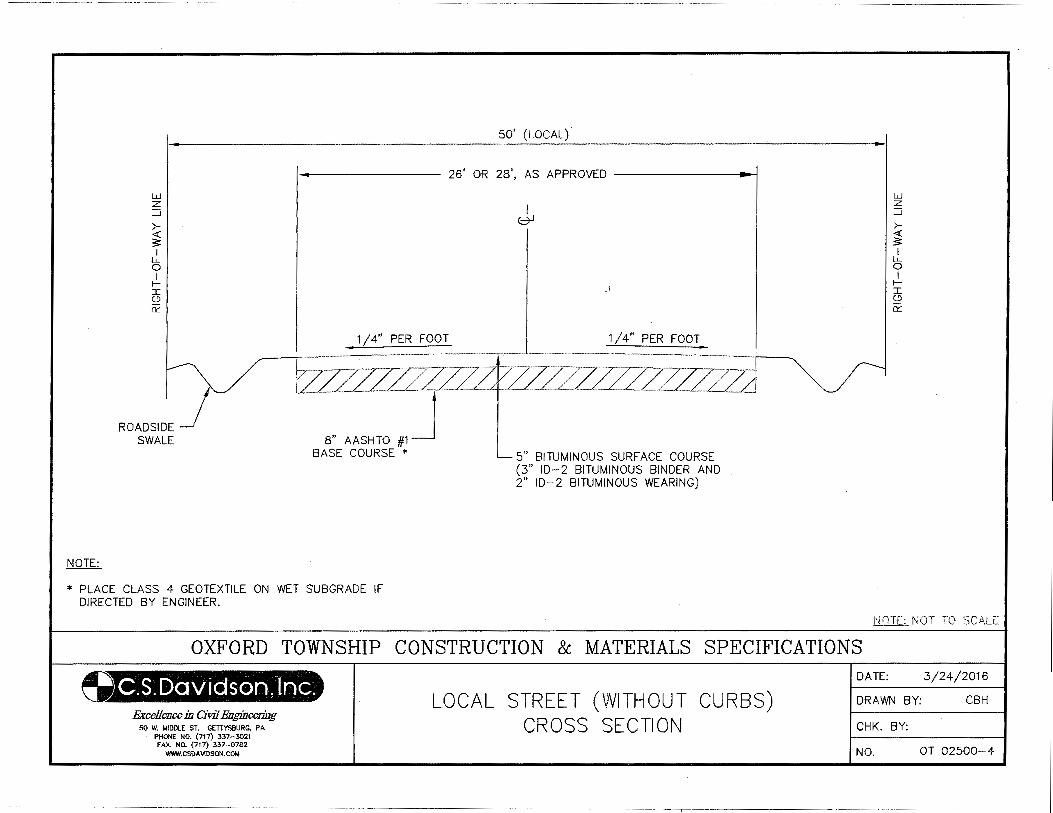
50' (LOCAL).
I 26' OR 28', AS APPROVED --------.1
NOTE:
w z ::J
><(
~ I
LL.. 0 I
II 0 02
ROADSIDE} SWALE
1/4" PER FOOT
* PLACE CLASS 4 GEOTEXTILE ON WET SUBGRADE IF DIRECTED BY ENGINEER.
I (;:::71
1/4" PER FOOT
5" BITUMINOUS SURFACE COURSE (3" ID-2 BITUMINOUS BINDER AND 2" ID-2 BITUMINOUS WEARING)
w z ::J
><(
~ I
LL.. 0 I
II 0 02
NOTE: NOT TO SCALE
OXFORD TOWNSHIP CONSTRUCTION & MATERIALS SPECIFICATIONS
Excellence in Civil Engineering 50 W. MIDDLE ST. GETTYSBURG, PA
PHONE NO. (717) 337-3021 FAX. NO. (717) 337-0782
WWW.CSDA V!DSON.COM
LOCAL STREET (WITHOUT CURBS) CROSS SECTION
DATE: 3/24/2016
DRAWN BY: CBH
CHK. BY:
NO. OT 02500-4
·----·- ~------------··-------------- --~---------------------
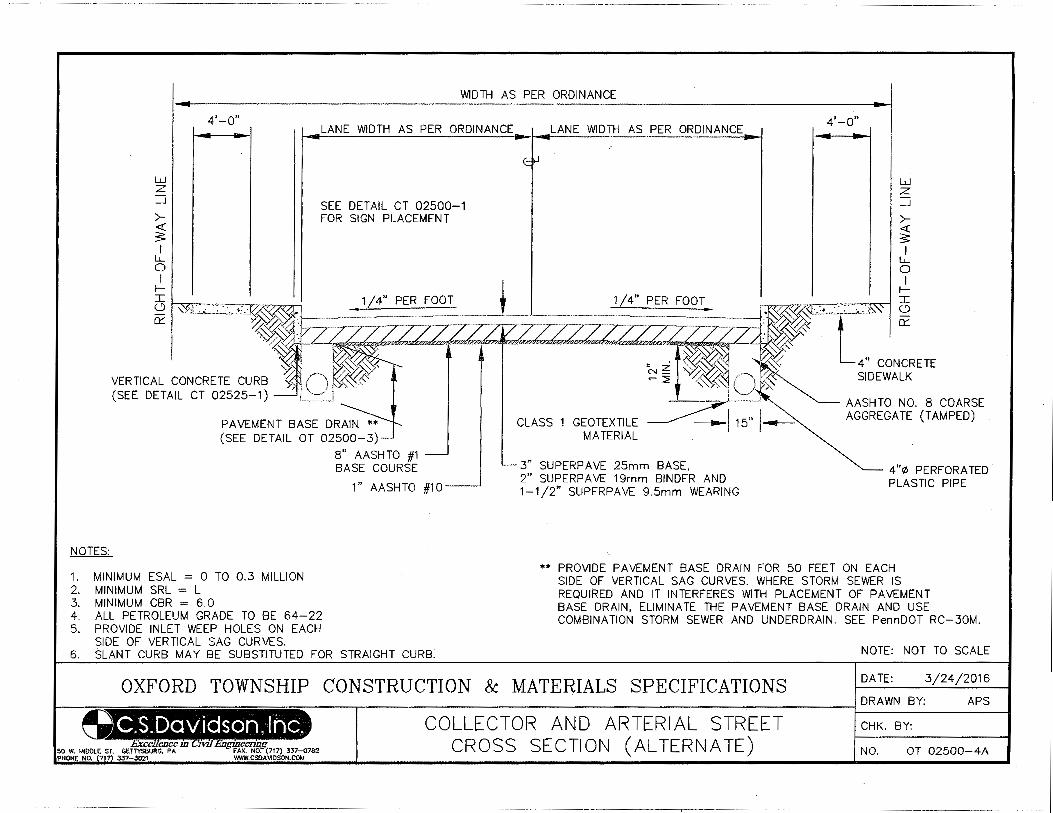
WIDTH AS PER ORDINANCE
w z __j
><(
3: I
Li.. 0 I
II 0 0:::
4'-0" LANE WIDTH AS PER ORDINANCE
SEE DETAIL CT 02500-1 FOR SIGN PLACEMENT
PAVEMENT BASE DRAIN (SEE DETAIL OT 02500-3)
NOTES:
1. MINIMUM ESAL = 0 TO 0.3 MILLION 2. MINIMUM SRL = L 3. MINIMUM CBR = 6.0 4. ALL PETROLEUM GRADE TO BE 64-22 5. PROVIDE INLET WEEP HOLES ON EACH
SIDE OF VERTICAL SAG CURVES.
8" AASHTO #1 BASE COURSE
1" AASHTO #10
6. SLANT CURB MAY BE SUBSTITUTED FOR STRAIGHT CURB.
LANE WIDTH AS PER ORDINANCE
CLASS 1
3" SUPERPAVE 25mm BASE, 2" SUPERPAVE 19mm BINDER AND 1-1/2" SUPERPAVE 9.5mm WEARING
4'-o"
w z __j
><(
3: I
Li.. 0 I
II 0
AASHTO NO. 8 COARSE AGGREGATE (TAMPED)
4"0 PERF ORA TED PLASTIC PIPE
** PROVIDE PAVEMENT BASE DRAIN FOR 50 FEET ON EACH SIDE OF VERTICAL SAG CURVES. WHERE STORM SEWER IS REQUIRED AND IT INTERFERES WITH PLACEMENT OF PAVEMENT BASE DRAIN, ELIMINATE THE PAVEMENT BASE DRAIN AND USE COMBINATION STORM SEWER AND UNDERDRAIN. SEE PennDOT RC-30M.
NOTE: NOT TO SCALE
OXFORD TOWNSHIP CONSTRUCTION & MATERIALS SPECIFICATIONS DATE: 3 6
COLLECTOR AND ARTERIAL STREET CROSS SECTION (ALTERNATE)
DRAWN BY: APS
CHK. BY:
NO. OT 02500-4A
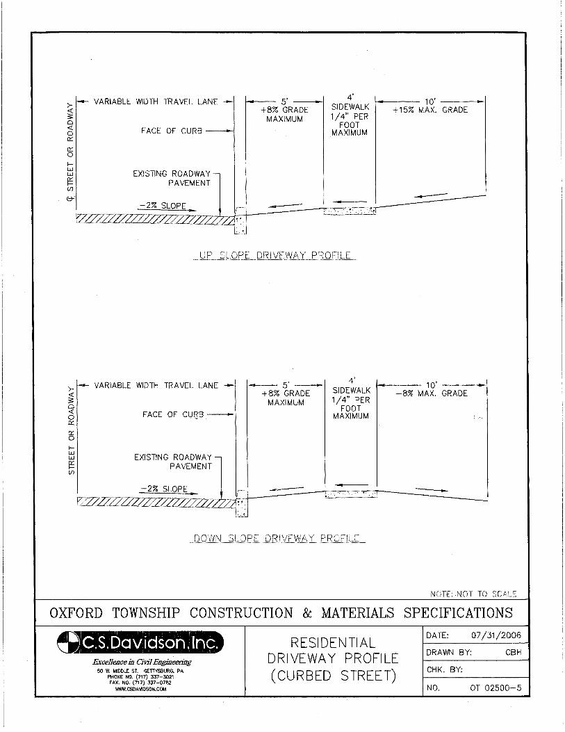
>-~ a <( 0 0:::
0::: 0 fw w g: (/)
>-~ a <( 0 0:::
0::: 0 fw w g: (/)
VARIABLE WIDTH TRAVEL LANE ---
FACE OF CURB-
EXISTING ROADWAY PAVEMENT
-2% SLOPE
~_zzr~.<...£· .~~ '-"~"'"-l
VARIABLE WIDTH TRAVEL LANE --
FACE OF CU!3B ---1
EXISTING ROADWAY l PAVEMENT
-2% SLOPE
trr-2L7-.f::ZLZ--r7...,~~=2L"W:::'"7'2ZZ'"ZZ2z:2ZZ7.2222
1---- 5' --; +8% GRADE
MAXIMUM
1---s·--1 +8% GRADE
MAXIMUM
4' r---- 10' ___ ,
SIDEWALK +15% MAX. GRADE 1/4" PER
FOOT MAXIMUM
4' 1---- 10' ---1 SIDEWALK -8% MAX. GRADE 1/4" PER
FOOT MAXIMUM
NOTE: NOT TO SCALE
OXFORD TOWNSHIP CONSTRUCTION & MATERIALS SPECIFICATIONS
G.S.Davidson, Inc. ExccUence in Civil Engineering
50 W. MIDDLE ST. GETTYSBURG. PA PHONE NO. (717) 337-3021 FAX. NO. (717} 337-0782
WWW.CSDAVIOSON.COM
RESIDENTIAL DRIVEWAY PROFILE (CURBED STREET)
DATE: 07/31/2006
DRAWN BY: CBH
CHK. BY:
NO. OT 02500-5
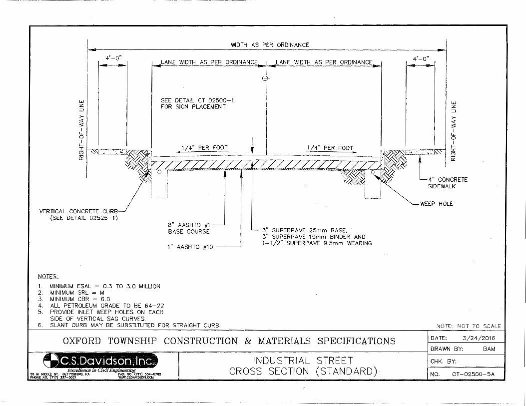
w z :::J
4'-o"
WIDTH AS PER ORDINANCE
LANE WIDTH AS PER ORDINANCE
SEE DETAIL CT 02500-1 FOR SIGN PLACEMENT
LANE WIDTH AS PER ORDINANCE 4'-o"
w z :::J
r r ~ ~ 3 3 I I
~ t ~ I I j: . ·~--~. 1 I 4" PER FOOT 1 I 4" PER FOOT . . . . . j: (.!) '" ~· .• ··.·' ~1 • ·,::__.:. . . . <.?
~<2·- -·-rr--T7zz-7-77ZZJ7zz:zzzzzzz~ zz·- --'T~Jy~» L Ck:
~~~__;zzz-~ 4" CONCRETE
VERTICAL CONCRETE CURB (SEE DETAIL 02525-1)
NOTES:
1. MINIMUM ESAL = 0.3 TO 3.0 MILLION 2. MINIMUM SRL = M 3. MINIMUM CBR = 6.0 4. ALL PETROLEUM GRADE TO BE 64-22 5. PROVIDE INLET WEEP HOLES ON EACH
SIDE OF VERTICAL SAG CURVES.
8" AASHTO #1 BASE COURSE
1" AASHTO #1 0 ---
3" SUPERPAVE 25mm BASE, 3" SUPERPAVE 19mm BINDER AND 1-112" SUPERPAVE 9.5mm WEARING
6. SLANT CURB MAY BE SUBSTITUTED FOR STRAIGHT CURB.
OXFORD TOWNSHIP CONSTRUCTION & MATERIALS SPECIFICATIONS
INDUSTRIAL STREET CROSS SECTION (STANDARD)
SIDEWALK
WEEP HOLE
DATE: 3
DRAWN BY: BAM
CHK. BY:
NO. OT-02500-SA
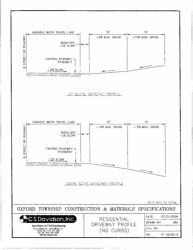
>-~ 0 <( 0 0:::
0::: 0 f-
VARIABLE WIDTH TRAVEL LANE
SHOULDER -2% SLOPE
~ PAVEMENT (/)
(::71
10' 10'
+6% MAX. GRADE +15% MAX. GRADE
[;:1 EXISTING ROADW1Y
-2% SLOPE ~__!~ _ __::-~::=:=----f2LZZ27_L7z:z:'l~ Ll
>-~ 0 <( 0 0:::
a::: 0
f-
VARIABLE WIDTH TRAVEL LANE
SHOULDER -2% SLOPE
~ PAVEMENT (/)
(::71 -2% SLOPE
10' 10'
-10% MAX. GRADE -15% MAX. GRADE
[;:1 EXISTING ROADWA]
rL7227ZZ27EZ?Z?Z?.ZZZZZ2 ~·/":~;;--"! ---
~JOlT.: NOT TO
OXFORD TOWNSHIP CONSTRUCTION & MATERIALS SPECIFICATIONS
Excellence in Civil Engineering 50 W. MIDDLE ST. GETTYSBURG, PA
PHONE NO. (717) 337-3021 FAX. NO. (717) 337-0782
WWW.CSDAVIOSON.COM
RESIDENTIAL DRIVEWAY PROFILE
(NO CURBS)
DATE: 07/31/2006
DRAWN BY: CBH
CHK. BY:
NO. OT 02500-6
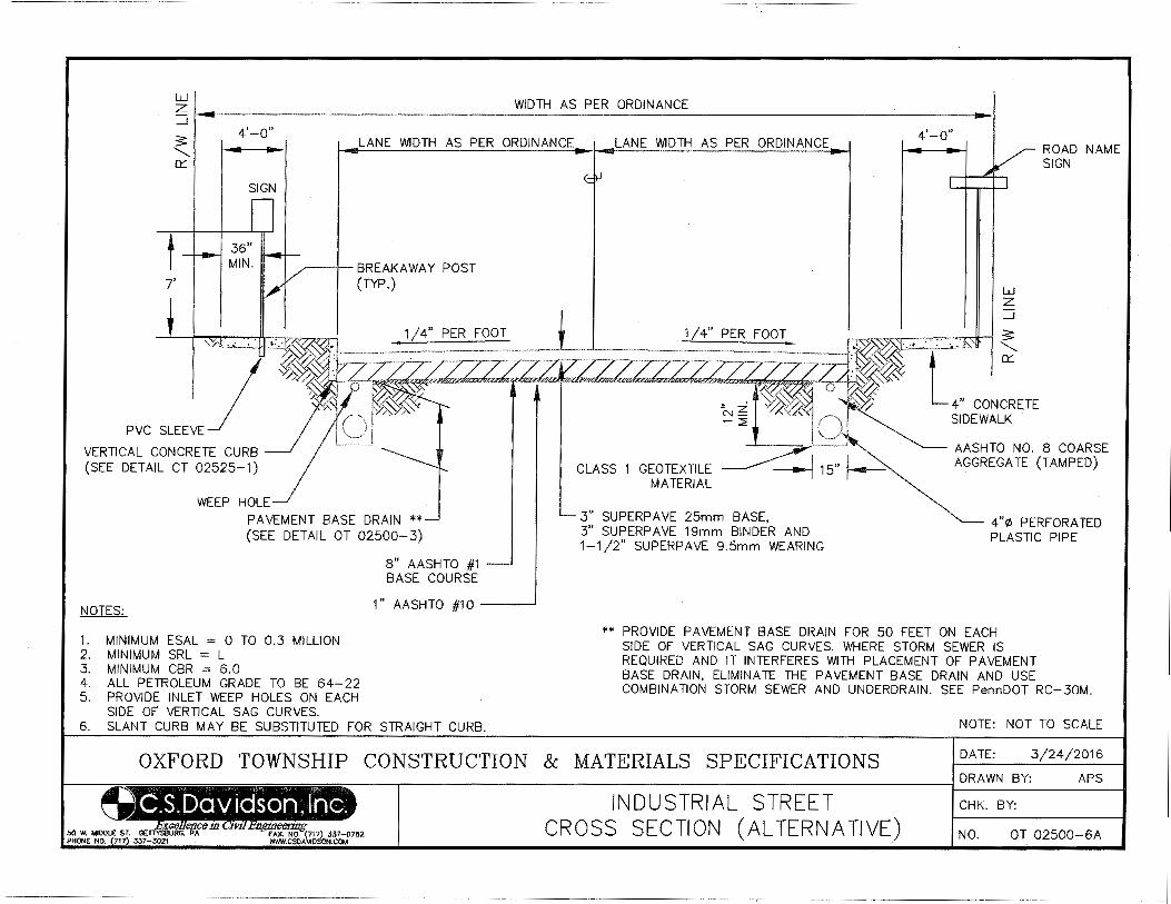
UJ z _j l--.---------------------------------------------------------------------------------------------------1 3:'
4'-0"
.......... 0::::
SIGN
D
LANE WIDTH AS PER ORDINANCE LANE WIDTH AS PER ORDINANCE
~--+- BREAKAWAY POST (TYP.)
1/4" PER FOOT
4'-0"
UJ z _j
ROAD NAME SIGN
;7z·~-----;-= .. :.; ... ==;=:::;=--~-=====:: .. =--~-_j. ~ ~~· ... ,~~ :s: ?if~s,,<G"•'~"'~""**,.,'·"·"'··· . ZZZZT/Z2~7zz , ~'1<~ L--·~~.,. I '.:> . a 1 !, ..... ~.~~-"'~"'···'"·'~"~~ .,~""·'~"'··· ""'« ... ·r· o : ~~"':(( '-'-
• z ~%~ ~~~ S! ~ %(Y:;<":-j ):/ 4" CONCRETE
VERTICAL CONCRETE CURB (SEE DETAIL CT 02525-1)
WEEP HOLE
PAVEMENT BASE DRAIN ** (SEE DETAIL OT 02500-3)
NOTES:
1. MINIMUM ESAL = 0 TO 0.3 MILLION 2. MINIMUM SRL = L 3. · MINIMUM CBR = 6.0 4. ALL PETROLEUM GRADE TO BE 64-22 5. PROVIDE INLET WEEP HOLES ON EACH
SIDE OF VERTICAL SAG CURVES.
8" AASHTO #1 BASE COURSE
1" AASHTO #1 0 __ __J
6. SLANT CURB MAY BE SUBSTITUTED FOR STRAIGHT CURB.
u ;--....,_ SIDEWALK
~~-----~~ '---- AASHTO NO.8 COARSE
CLASS 1 GEOTEXTILE MATERIAL
--J 15" AGGREGATE (TAMPED)
3" SUPERP AVE 25mm BASE, 3" SUPERP AVE 19mm BINDER AND 1-1/2" SUPERPAVE 9.5mm WEARING
4"~ PERF ORA TED PLASTIC PIPE
** PROVIDE PAVEMENT BASE DRAIN FOR 50 FEET ON EACH SIDE OF VERTICAL SAG CURVES. WHERE STORM SEWER IS REQUIRED AND IT INTERFERES WITH PLACEMENT OF PAVEMENT BASE DRAIN, ELIMINATE THE PAVEMENT BASE DRAIN AND USE COMBINATION STORM SEWER AND UNDERDRAIN. SEE PennDOT RC-30M.
NOTE: NOT TO SCALE
OXFORD TOWNSHIP CONSTRUCTION & MATERIALS SPECIFICATIONS DATE: 3/24/2016
DRAWN BY: APS
I INDUSTRIAL STREET CHK. BY:
CROSS SECTION (ALTERNATIVE) NO. OT 02500-6A
02525-1
SECTION 02525
CEMENT CONCRETE CURB & SIDEWALK
PART 1 - GENERAL
1.01 DESCRIPTION
A. The work of this section includes, but is not limited to:
1. Subgrade preparation
2. Construction of cement concrete curb and sidewalk
3. Construction of handicap ramps
4. Construction of stamped (patterned) and colored concrete sidewalk
B. Applicable Standard Details:
OT 02525-1 Vertical Concrete Curb Details
OT 02525-2 Slant Concrete Curb Details
OT 02525-3 Concrete Sidewalk Detail
OT 02525-4 Concrete Sidewalk at Driveway Details
OT 02525-5 Type 1 Double Curb Ramp Detail
OT 02525-6 Type 1 Double Curb Ramp Details (Alternate)
OT 02525-7 Type 1 Curb Ramp Detail
OT 02525-8 Type 1A Curb Ramp Detail
OT 02525-9 Type 2 Curb Ramp Detail
OT 02525-10 Type 3 Parallel Curb Ramp Detail
OT 02525-11 Type 3 Perpendicular Curb Detail
OT 02525-12 Type 4 Combination Curb Ramp Detail
OT 02525-13 Type 4A Combination Curb Ramp Detail
OT 02525-14 Detectable Warning Surface Detail
OT 02525-15 Roof Leader Under Sidewalk Detail
1.02 QUALITY ASSURANCE
A. Reference Standards:
1. Pennsylvania Department of Transportation (PennDOT), latest revision:
Publication 408, Specifications
Publication 213, Work Zone Traffic Control Guidelines
Department of Justice, Code for Regulations, ADA Standards for Accessible Design
2. American Society for Testing and Materials (ASTM):
A185 Standard Specification for Welded Steel Wire Fabric for Concrete Reinforcement
A615 Standard Specification for Deformed and Plain Billet-Steel Bars for Concrete Reinforcement
C94 Specification for Ready-Mixed Concrete
C143 Test Method for Slump of Hydraulic Cement Concrete
C231 Test Method for Air Content of Freshly Mixed Concrete by the Pressure Method
C309 Specification for Liquid Membrane-Forming Compounds for Curing Concrete
D994 Specification for Preformed Expansion Joint Filler for Concrete (Bituminous Type)
E329 Specification for Agencies Engaged in the Testing and/or Inspection of Materials used in
Construction
02525-2
B. Inspections:
1. Inspection by the Municipality will at a minimum be made of the subgrade, formwork, and any steel
prior to placement of the concrete.
1.03 JOB CONDITIONS
A. Control of traffic:
1. Take measures to control traffic during all operations. Do not allow traffic on newly placed concrete
until adequate strength has been attained.
2. Employ Traffic Control Guidelines measures in accordance with Publication 213, Work Zone Traffic
Control Guidelines.
B. Coordination with utilities:
1. Coordinate all necessary adjustments of existing utilities to accommodate this work.
2. Provide access to the site for utility work.
PART 2 PRODUCTS
2.01 CONCRETE
A. Portland cement concrete shall be air-entrained and have a minimum 28 day compressive strength shall be
3,300 psi.
B. Cement Concrete criteria for curbs and sidewalks:
Slump: 1" minimum, 4" maximum
Air Content: 4.5% minimum, 7.5% maximum
Temperature: 50F minimum, 90F maximum
C. For slip formed curb, same as above except with a maximum slump of 1-1/2".
D. For replacement of curb and sidewalk at existing driveways, use air-entrained, PennDOT Class HES (High
Early Strength).
2.02 FORMS
A. General requirements:
1. Forms shall be coated with a form release agent just prior to placement of concrete.
B. Straight curbing (or radius greater than 40 feet):
1. Approved metal forms.
2. Wood forms, not less than 2 inch nominal thickness, planed on finish side.
C. Radius curbing:
1. Approved metal forms.
2. Fabricated plywood or hardboard forms.
02525-3
D. Curbing repairs (less than 10 feet):
1. Approved metal forms.
2. Adjust to match existing conditions (vertical 6" x 8" x 22" or rolled 24" x 10¾").
E. Machine-placed curbing:
1. Straight or radius curbing may be placed with a self-propelled machine approved by the Municipality.
2.03 REINFORCEMENT
A. Welded Wire Fabric - ASTM A185. Size and spacing as shown on Standard Details.
B. Reinforcing Bars - ASTM A615, Grade 60 billet steel. Size and spacing as shown on Standard Details.
2.04 JOINT MATERIAL
A. Joint Filler - Premolded expansion joint material shall be fiber joint filler conforming to ASTM D994.
2.05 FORM COATING MATERIALS
A. Form release agents shall be non-staining, liquid chemical coatings free of kerosene, oil and was which
effectively prevent absorption of moisture into the forms and bonding of the concrete to the forms.
2.06 CONCRETE CURING COMPOUNDS
A. Curing compounds shall be clear, non-staining liquid coatings containing no oil or wax and conforming to
ASTM C309, such as Safe-Cure, Sealtight 1100, Klear Seal R-75 or Enviocure Clear 500, or similar
material.
2.07 STAMPED COLORED CONCRETE
A. Concrete, reinforcement, joint material and forms - see above paragraphs
B. Template Pattern - "old brick runningboard" by Matcrete (1-800-777-7063), or equal
C. Pigment - Brick Red #10160 by David Colors, Beltsville, MD , or equal
D. Clear Sealer - Sonneborn #800 as manufactured by Sonneborn , or equal
E. Template release agent - dry blend powder
PART 3 EXECUTION
3.01 CURB CONSTRUCTION
A. Excavate to required depth, remove and dispose of material, including existing curbs, and compact the
subgrade material to a firm, even surface.
B. Saw cut existing pavement a minimum of 12" from face of new curb. Exposed edges of existing work shall
be smooth and square.
C. Forms shall be placed as appropriate to the type of curbing on 2 sides (front and back). Forms shall be
securely braced to limit deflection during placement of concrete.
02525-4
D. Provide openings through curb for drainage pipes. Install one, 2'-0" long, #4 reinforcing bar in the middle
of curb centered above the pipe as per Standard Detail.
E. Concrete shall be placed in accordance with Section 030000, Paragraph 3.05.
F. Variation of more than 1/8” from the established line and grade shall be cause for rejection of that portion of
work.
G. Form or saw contraction joints 3/16" wide and 2" deep at 10-foot maximum intervals on 2 sides (front and
top). Saw as soon as possible after the concrete has set sufficiently to preclude raveling during the sawing
and before any shrinkage cracking occurs in the concrete, but in no case later than 24 hours following
completion of the curb placement.
H. Provide ½" expansion joints at 60-foot intervals, at the end of each pour, and at the beginning and end of all
radii. ½" expansion joint material shall also separate curb from adjacent sidewalks, poles, hydrants, walls
and other permanent structures, except that 3/4" thick expansion joint material shall be provided at storm
inlets.
I. The last three feet of curb shall be tapered to a 1-1/2" reveal with expansion joint at the beginning of taper.
J. Finish top surface with wood floats. Provide depressions for drainage, driveways, and ramps for the
handicapped as directed by the Municipality. Tool all exposed edges to the specified radius.
K. Do not remove forms until concrete has set. Begin proper curing immediately after placement.
L. Reapply curing compound 30 days following first application.
M. For slip formed curb, uniformly feed the concrete to the machine so the concrete maintains the shape of the
section, without slumping after extrusion. Voids or honeycomb on the surface of the finished curb will not
be allowed. Immediately after extrusion, perform any additional surface finishing required.
N. Correct minor irregularities with a carborundum stone or mortar comprised of two parts fine aggregate to
one part cement.
3.02 SIDEWALK CONSTRUCTION
A. Excavate to required depth and width, remove and dispose of material, including any existing sidewalks, and
compact the subgrade material to a firm, even surface.
B. Exposed edges of existing work shall be smooth and square.
C. Construct ramps for handicapped persons at all street crossings (as required by ADA regulations) as directed
by the Municipality. Handicap ramps shall be 6" thick concrete. All handicap ramps shall have detectible
warning domes as shown on drawing OT-02525-6.
D. Sidewalks across sanitary sewer or storm sewer easements shall be 8" thick.
E. Spread AASHTO No. 57 aggregate and compact to the thickness shown on the Standard Details.
F. Concrete shall be placed in accordance with Section 030000, Paragraph 3.05. Hand float to desired line and
grade.
G. Score contraction joints at 5-foot intervals to sufficient depth to insure cracking at the joint. Do not saw cut
the contraction joints without prior approval from the Municipality. Also score sidewalks over each
drainage pipe placed underneath.
02525-5
H. Provide 1/4" expansion joint at 30-foot intervals and at the end of each pour. Place ½" expansion joint
material at adjacent curb, poles, hydrants, walls, and other permanent structures.
I. Apply light broom finish immediately after float finish.
J. Provide depressions for driveways, downspouts, and drainage as directed by the Municipality or shown on
the drawings. Wherever possible roof leaders shall be placed under the sidewalks in lieu of depressions.
K. Begin proper curing immediately following placement.
L. Monolithic sidewalk and curb will not be allowed at a radius handicap ramp without approval from the
Municipality.
3.03 STAMPED AND COLORED CONCRETE SIDEWALKS
A. Excavate, place stone base and place expansion joints and reinforcing similarly to plain concrete sidewalks.
B. Pigment must be thoroughly mixed throughout concrete using ratios consistent with manufacturer's
recommendations. Apply float finish and edge.
C. Sprinkle release agent onto fresh concrete prior to stamping with template.
D. Remove release agent by power washing approximately 24 hours after stamping is complete, or as
recommended by the manufacturer.
E. Apply clear sealer to all concrete surfaces.
F. Release agent, pigment and sealer must be from same manufacturer or proven to be compatible with each
other.
3.04 HANDICAP RAMPS
The following requirements shall be followed in all construction of handicap ramps, where these requirements
are less stringent or different from ADA requirement, the ADA requirements shall govern.
A. Sidewalks
1. Sidewalk cross slopes shall not exceed 2%.
2. A minimum of 36” pedestrian path of travel, clear of obstructions, grates and other openings, shall be
provided along the run of a sidewalk. A 42” pedestrian path of travel is preferred.
3. Objects shall not project more than 4 inches into the pedestrian path of travel between 27” and 80” above
the sidewalk surface unless a detection barrier is provided beneath the object at a maximum of 4” less
than the projection into the pedestrian path of travel.
B. Driveway aprons
1. Driveway aprons shall provide a minimum of 36” pedestrian path of travel, clear of obstructions, grates
and other openings, in line with the run of a sidewalk with a maximum cross slope of 2%.
C. Curb ramps
1. Curb ramps shall have a maximum slope of 1:12.
02525-6
2. The sum of the percent slope of the curb ramp and the roadway cross slope, when added together as
positive values, shall not exceed 13%.
3. Curb ramps shall have a minimum width of 4 feet.
4. Curb ramps shall be constructed flush, without a reveal, at the edge of the roadway surface.
5. Curb ramps shall be perpendicular to the curb.
6. Curb ramps shall be within the crosswalk if a crosswalk exists.
7. Flares shall be provided at a maximum slope of 1:10 when a curb ramp is located in the pedestrian path
of travel.
8. Return curbs shall only be provided in areas outside the pedestrian path of travel or walkway.
D. Diagonal Curb ramps
1. Diagonal curb ramps shall not be permitted in new construction. For projects proposing improvements
to handicap facilities, diagonal curb ramps shall be permitted on a case to case basis as determined by the
Municipality.
2. Diagonal curb ramps shall have a minimum 4’x 4’ maneuvering space at the bottom of the ramp. The
maneuvering space shall have a maximum 2% cross-slope in any direction. The maneuvering space
shall be within the projected curb line measured from the point of curvature and point of tangent to the
point of intersection of the project curb lines. The maneuvering space shall be within the crosswalk
delineation.
3. Diagonal curb ramps having flared sides shall have at least a 24 inch long segment of straight curb
located on each side of the curb ramp and within the marked crossings.
E. Detectable Warning Surfaces
1. Detectable warnings shall provide significantly contrasting texture and light reflective color.
2. Detectable warnings shall be the width of the curb ramp and two feet in depth.
3. Detectable warnings shall be provided at a maximum 8” from the roadway surface.
4. Detectable warnings may be considered part of the ramp portion of the curb ramp.
5. Truncated domes within the detectable warnings surface shall provide domes in alignment with the
direction of travel.
6. Truncated domes shall have a diameter of 0.9 inches, a height of 0.2 inches and a center to center
spacing of 2.35 inches and shall contrast visually with adjoining surfaces, either light on dark, or dark on
light.
F. Landing Areas
1. A landing area shall be provided at any curb ramp where there is more than one pedestrian path of travel
accessible to the curb ramp.
2. Landing areas shall be provided as required in accordance with Federal regulations.
02525-7
3. Landing areas shall be a minimum 5’ X 5’ area, clear of any obstructions, with a maximum slope of 2%
in any direction. 4’ X 4’ landing with a 60” clear turning diameter maybe be permitted if a written
report of noncompliance is submitted for each location proposed and approved by the Engineer.
4. Landing areas shall be provided at the following locations:
every location the pedestrian path of travel would change direction
at any location where the rise of a ramp exceeds 30 inches.
5. The landing area shall be at least as wide as the ramp run leading to it.
3.05 BACKFILLING AND RESTORATION
A. Temporary backfill at curbs shall consist of select granular material front and back, to within 8" of top of
curb.
B. Restore adjacent areas in kind.
END OF SECTION
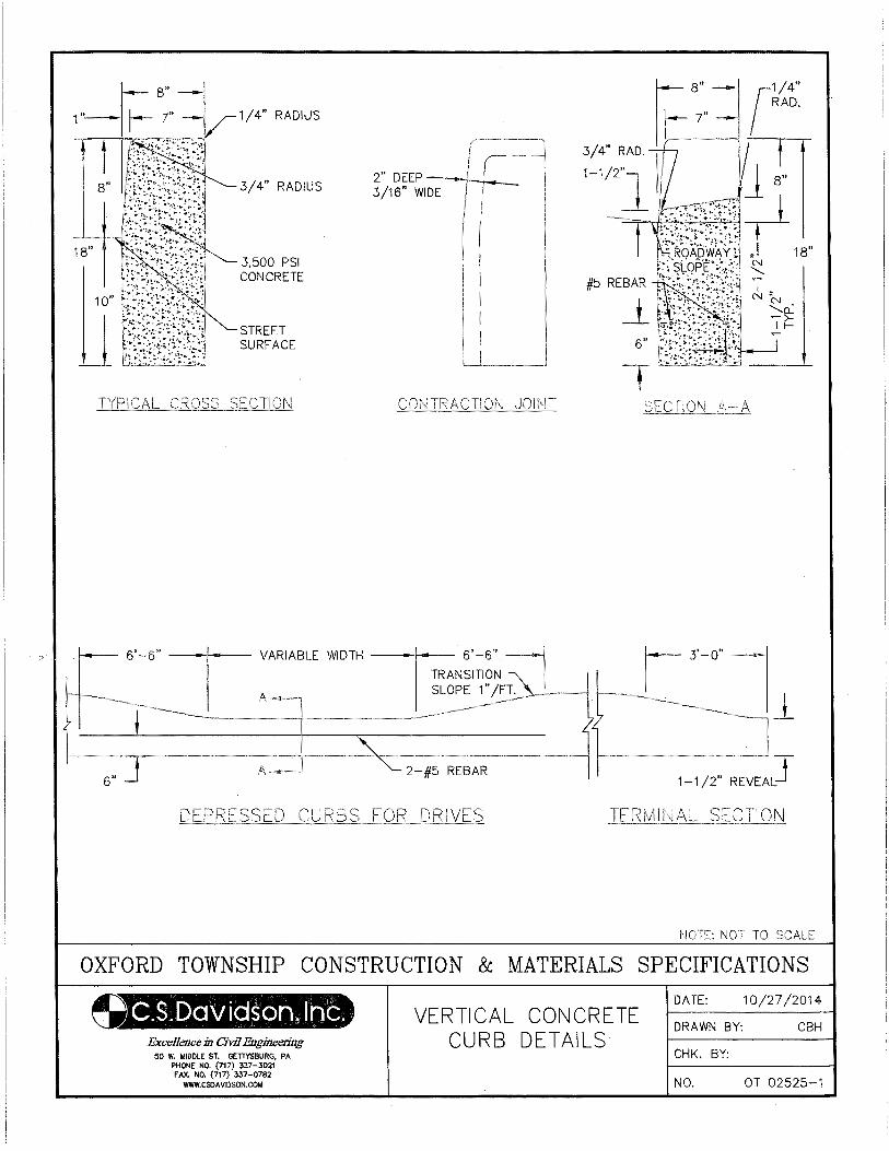
u 3,500 PSI CONCRETE
STREET SURFACE
A
2" DEEP 3/16" WIDE
( I -II
2-#5 REBAR
_t
1-1/2" REVEAL J
NOTE: NOT TO SCALE
OXFORD TOWNSHIP CONSTRUCTION & MATERIALS SPECIFICATIONS
Excellence in Civil Engineering 50 W. MIDDLE ST. GETTYSBURG, PA
PHONE NO. (717) 337-3021 FAX. NO. (717) 337-0782
WWW.CSOA VIOSON.COM
VERTICAL CONCRETE CURB DETAILS
DATE: 10/27/2014
DRAWN BY: CBH
CHK. BY:
NO. OT 02525-1
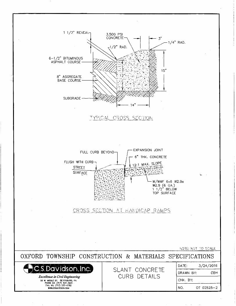
1 1 /2" REVEAL
6-1/2" BITUMINOUS ASPHALT COURSE -----1....,.._/
8" AGGREGATE BASE COURSE ---1~
3,500 PSI CONCRETE
15"
NOTE: NOT TO SCALE
OXFORD TOWNSHIP CONSTRUCTION & MATERIALS SPECIFICATIONS
Excellence in Civil Engineering 50 W, MIDDLE ST. GETTYSBURG, PA
PHONE NO. (717) 337-3021 fAX. NO. (717) 337-0782
WWW.CSDAVIDSON.COM
SLANT CONCRETE CURB DETAILS
DATE: 3/24/2016
DRAWN BY: CBH
CHK. BY:
NO. OT 02525-2
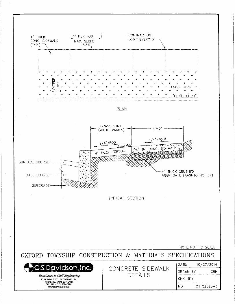
HICK C. SIDEWALK
4" T CON (TYP .)~
\
"' "' "' "'
1" PER FOOT
MAX. SLOPE 8.3%
"' "' "' "' "'
~~-----~----
"' ...
CONTRACTION
JOINT EVERY 5' \
"' "' ''"' "' ........ -. "'""''"'"'11-~-...----~-...
4" THICK CRUSHED AGGREGATE (AASHTO NO. 57)
NOTE: NOT TO SCALE
OXFORD TOWNSHIP CONSTRUCTION & MATERIALS SPECIFICATIONS
~.S.[L)aviason,lnc. Excel1C11ce in Civil Engineering
50 W. MIDDLE ST. GETTYSBURG, PA PHONE NO. (717) 337-3021
FAX. NO. (717) 337-0782 WWW.CSOAVIDSON.COM
CONCRETE SIDEWALK DETAILS
DATE: 10/27/2014
DRAWN BY: CBH
CHK. BY:
NO. OT 02525-3
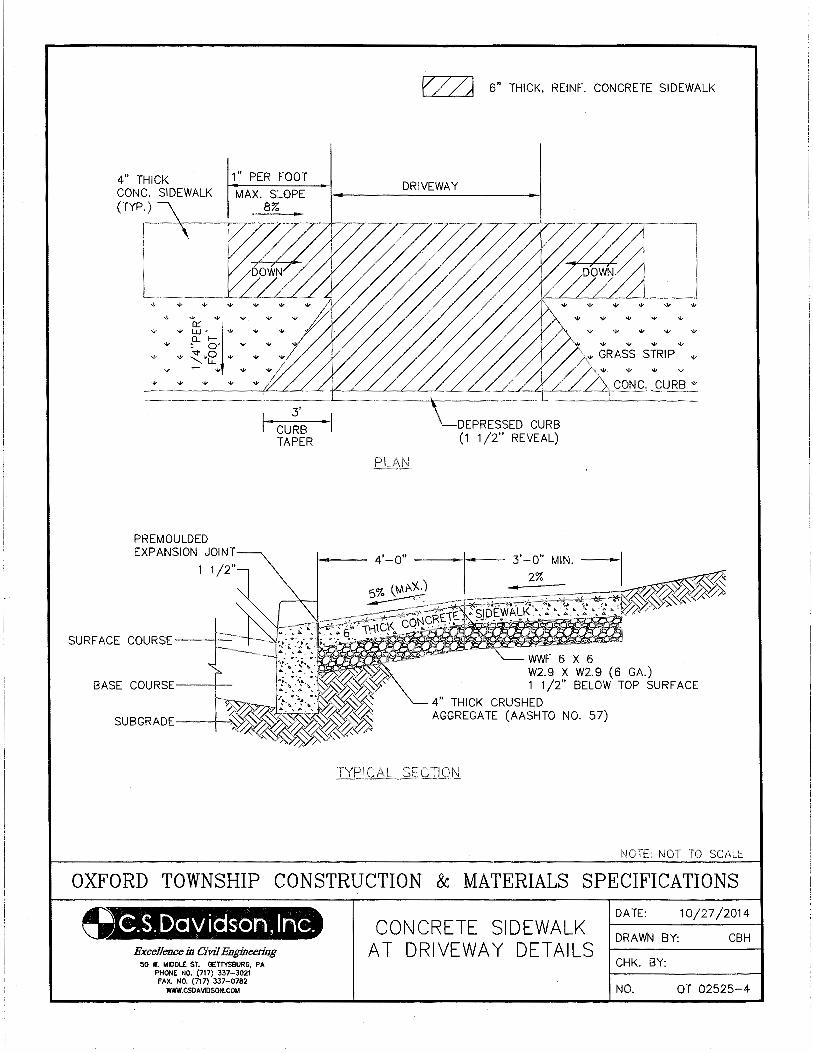
4" THICK CONC. SIDEWALK
PREMOULDED EXPANSION JOINT
1 1 /2"
3'
I· CURB ·I TAPER
f/(/?J 6" THICK, REINF. CONCRETE SIDEWALK
DRIVEWAY
CONC. CURB -v
WWF6X6 W2.9 X W2.9 (6 GA.) 1 1 /2" BELOW TOP SURF ACE
4" THICK CRUSHED AGGREGATE (AASHTO NO. 57)
NOTE: NOT TO
OXFORD TOWNSHIP CONSTRUCTION & MATERIALS SPECIFICATIONS
~.s. I:Jav iason, Inc. ExceUCllce in Civil Engineering
50 W. MIDDLE ST. GETTYSBURG, PA PHONE NO. (717) 337-3021 FAX. NO. (717) 337-0782
WWW.CSDAVIDSON.COM
CONCRETE SIDEWALK AT DRIVEWAY DETAILS
DATE: 10/27/2014
DRAWN BY: CBH
CHK. BY:
NO. OT 02525-4
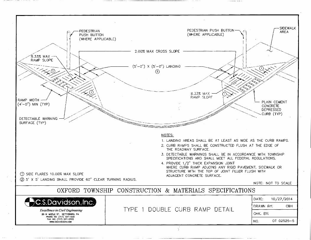
PEDESTRIAN
~~r PUSH Bu:;~~CABLE) 1 (WHERE
~I // 1 r~ ..-~3% MAX 'jl
/ RAMP SLOPE ' /
~···----~----- --~ ~~~~/~~::_~ / ~~~ 0 ":h ""~~ \ / ~\ AMP WIDTH )
R ' 0") MIN (TYP (4-
DETECT ABLE WARNING SURFACE (TYP)
G) SIDE FLARES 10.00% MAX SLOPE
2.00% MAX CROSS SLOPE
(5'-0") X (5'-0") LANDING
®
NOTES:
1. LANDING AREAS SHALL BE AT LEAST AS WIDE AS THE CURB RAMPS.
2. CURB RAMPS SHALL BE CONSTRUCTED FLUSH AT THE EDGE OF THE ROADWAY SURF ACE.
3. DETECTABLE WARNINGS SHALL BE IN ACCORDANCE WITH TOWNSHIP SPECIFICATIONS AND SHALL MEET ALL FEDERAL REGULATIONS.
4. PROVIDE 1/2" THICK EXPANSION JOINT WHERE CURB RAMP ADJOINS ANY RIGID PAVEMENT, SIDEWALK OR STRUCTURE WITH THE TOP OF JOINT FILLER FLUSH WITH ADJACENT CONCRETE SURFACE.
@ 5' X 5' LANDING SHALL PROVIDE 60" CLEAR TURNING RADIUS. NOTE: NOT TO SCALE
OXFORD TOWNSHIP CONSTRUCTION & MATERIALS SPECIFICATIONS
.Excellence in Civil .Engineering 50 W. MIDDLE ST. GETTYSBURG, PA
PHONE NO. (717) 337-3021 FAX. NO. (717) 337-0782
WWW.CSDAVIOSON.COM
TYPE 1 DOUBLE CURB RAMP DETAIL
DATE: 10/27/2014
DRAWN BY: CBH
CHK. BY:
NO. OT 02525-5
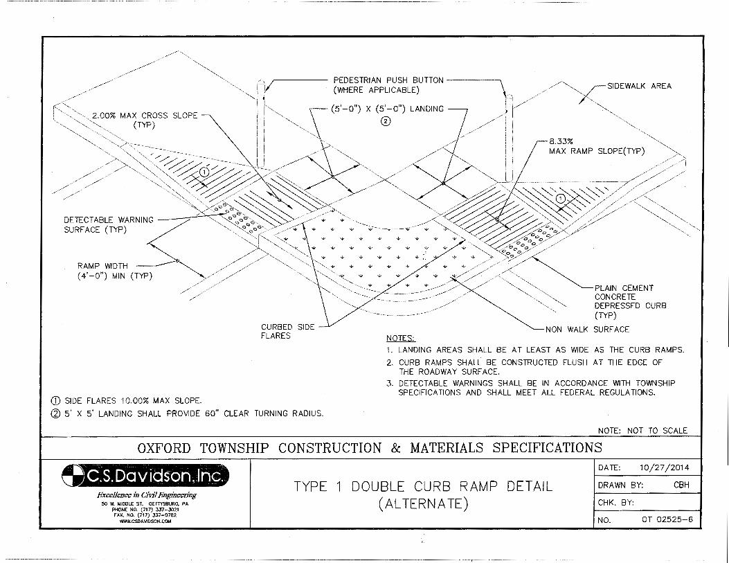
2.00% MAX CROSS SLOPE (TYP)
DETECTABLE WARNING ~ SURFACE (TYP)
RAMP WIDTH ( 4' -0") MIN (TYP)
([) SIDE FLARES 10.00% MAX SLOPE.
r----- PEDESTRIAN PUSH BUTTON ---~ SIDEWALK AREA
CURBED SIDE FLARES
(WHERE APPLICABLE)
(5'-0") X (5'-0") LANDING
0
NOTES:
8.33% MAX RAMP SLOPE(TYP)
PLAIN CEMENT CONCRETE DEPRESSED CURB (TYP)
NON WALK SURF ACE
1. LANDING AREAS SHALL BE AT LEAST AS WIDE AS THE CURB RAMPS.
2. CURB RAMPS SHALL BE CONSTRUCTED FLUSH AT THE EDGE OF THE ROADWAY SURFACE.
3. DETECTABLE WARNINGS SHALL BE IN ACCORDANCE WITH TOWNSHIP SPECIFICATIONS AND SHALL MEET ALL FEDERAL REGULATIONS.
~ 5' X 5' LANDING SHALL PROVIDE 60" CLEAR TURNING RADIUS.
NOTE: NOT TO SCALE
OXFORD TOWNSHIP CONSTRUCTION & MATERIALS SPECIFICATIONS
Excellence in O'vif Engineering 50 W. MIDDLE ST. GETIYSBURG, PA
PHONE NO. (71 7) 337-3021 FAX. NO. (717) 337-0782
WWW.CSDAVIDSON.COM
TYPE 1 DOUBLE CURB RAMP DETAIL (ALTERNATE)
DATE: 10/27/2014
DRAWN BY: CBH
CHK. BY:
NO. OT 02525-6
I
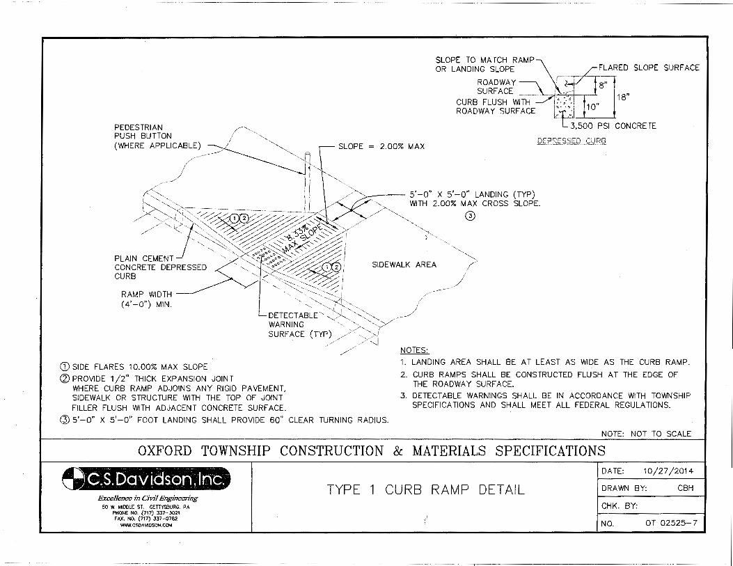
SLOPE TO MATCH RAMP0; OR LANDING SLOPE .r···--··----,. ,L:FLA~ED SLOPE SURFACE
ROADWAY\ I SURF ACE 1 . ,---
8"
18"
PEDESTRIAN PUSH BUTTON (WHERE APPLICABLE)
---__ ··1--L
SLOPE = 2.00% MAX
CURB FLUSH WITH ROADWAY SURF ACE
- -~~1',, // j -.....~
1<~:~"--.. ! _./>"·,,, .. 5' -0" X 5' -0" LANDING (TYP) L, '"" , / '"' ·-:>-<"·-~~:~~-// . ---- --- ---- --- I ,/-- /--< ~ Wl TH 2. 00% MAX CROSS SLOPE.
// '-.,_.>--( ,',,'·-.,~--_»/0~~/ ',/-~~--//···-- ... ____ 0 ' ,//,/"-,, :"]:~>-'->~><~~~ /~~~~~~""';,,//' ··-., __ _
, ,,, '~~,:>,:,,: 0/_// //<~~cb· c:;,V ~//;; f :~·,'-.....,, '•, '·,-. '"-. // / "' -.j._ :,.('--..' / //' ··--' ...... ;,~, ',..., / //·;; ......... - ....... \>'-~-.......' //-' /// ; '" ... ,,
'•' '- • <>" o'•, '-~'' // '• PLAIN CEMENT ··-. -~,x<::""-,s"'i~,/~ I ····-.. CONCRETE DEP~ESSED · ... >:-::.:~~~~~:~~~~ SIDEWALK AREA f> CURB ·· (''"""~:::··-.:_: ~ 1 ;
. -<~>::::·-., ~ i / RAMP WIDTH ·-.,····<--:--:: . .--I ( 4' -0") MIN '"- ····-.. , ··-----~?[····
. '',,, , ........ ,'-,I ':,,,,~"-"-
DETECTABLE'·· J>< ······>·-. WARNING w '"···-, ··<'--:/"
,, ,/ ... ,, f' SURFACE (TYP) ,/<- ·--.,!
_,/"/ ,/><:.] // NOTES:
:::71~
CONCRETE
G) SIDE FLARES 10.00% MAX SLOPE 1. LANDING AREA SHALL BE AT LEAST AS WIDE AS THE CURB RAMP.
@PROVIDE 1/2" THICK EXPANSION JOINT 2. CURB RAMPS SHALL BE CONSTRUCTED FLUSH AT THE EDGE OF WHERE CURB RAMP ADJOINS ANY RIGID PAVEMENT, THE ROADWAY SURFACE. SIDEWALK OR STRUCTURE WITH THE TOP OF JOINT 3. DETECTABLE WARNINGS SHALL BE IN ACCORDANCE WITH TOWNSHIP FILLER FLUSH WITH ADJACENT CONCRETE SURF ACE. SPECIFICATIONS AND SHALL MEET ALL FEDERAL REGULATIONS.
@ 5' -0" X 5' -0" FOOT LANDING SHALL PROVIDE 60" CLEAR TURNING RADIUS.
NOTE: NOT TO SCALE
OXFORD TOWNSHIP CONSTRUCTION & MATERIALS SPECIFICATIONS
Bxcellence in Civil .Engineering 50 W. MIDDLE ST. GETTYSBURG, PA
PHONE NO. (717) 337-3021 FAX. NO. (717) 337-0782
WWW.CSDA\IIDSON.COM
TYPE 1 CURB RAMP DETAIL
DATE: 10/27/2014
ORA WN BY: CBH
CHK. BY:
NO. OT 02525-7
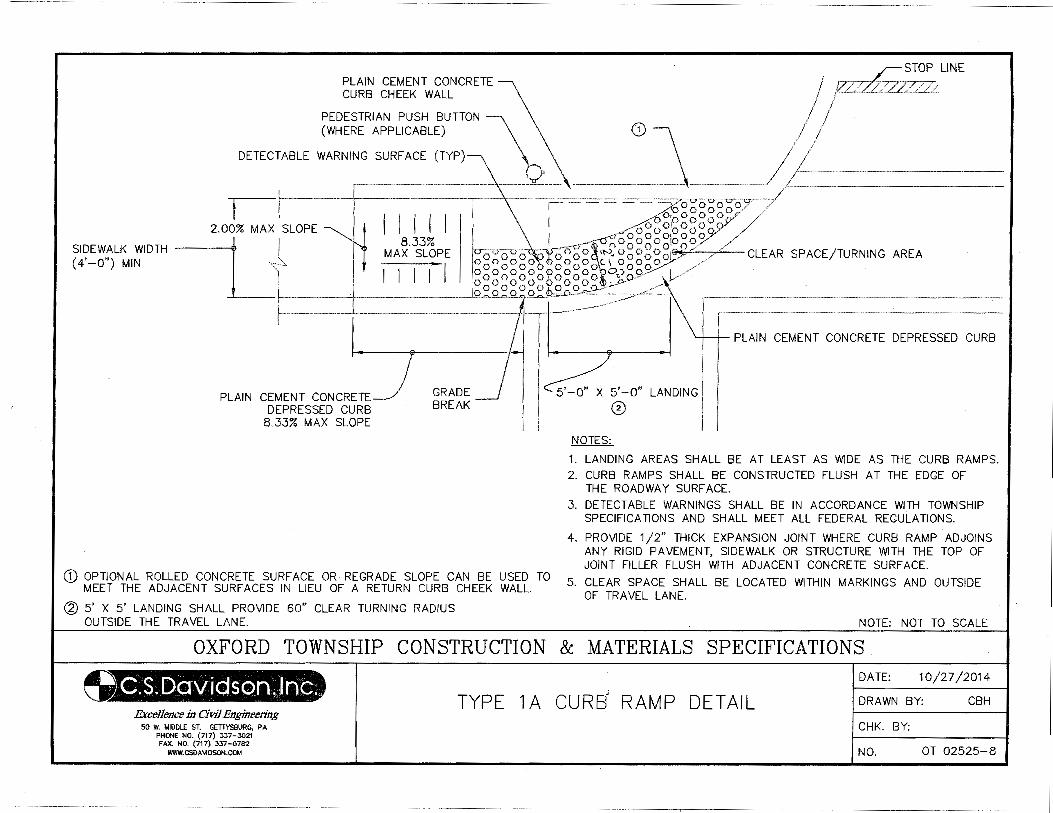
PLAIN CEMENT CONCRETE CURB CHEEK WALL
PEDESTRIAN PUSH BUTTON (WHERE APPLICABLE)
DETECTABLE WARNING SURFACE
LINE
CD
II I . ~~~~~o 2.00% MAX SLOPE nl I I I ~;o~o~:o~o~y
SIDEWALK WIDTH Ll I MA~·~3tiPE 0 0 0 0i>Q"~~-1t-:>~. ~~~~g~..,.:_;.o:;o;.£?':.__/.,./:.___CLEAR SPACE/TURNING AREA (4, O") MIN ~ o o o o :0 o o q o o o ' · - ~l I I I 1 I g~~gg~gog~~gg~ o~gfr
L ___ L ____ =- ~0==-~~--"'
PLAIN CEMENT CONCRETE DEPRESSED CURB
8.33% MAX SLOPE
GRADE BREAK
d) OPTIONAL ROLLED CONCRETE SURF ACE OR REGRADE SLOPE CAN BE USED TO MEET THE ADJACENT SURF ACES IN LIEU OF A RETURN CURB CHEEK WALL.
~ 5' X 5' LANDING SHALL PROVIDE 60" CLEAR TURNING RADIUS OUTSIDE THE TRAVEL LANE.
PLAIN CEMENT CONCRETE DEPRESSED CURB
LANDING
NOTES:
1. LANDING AREAS SHALL BE AT LEAST AS WIDE AS THE CURB RAMPS. 2. CURB RAMPS SHALL BE CONSTRUCTED FLUSH AT THE EDGE OF
THE ROADWAY SURF ACE.
3. DETECTABLE WARNINGS SHALL BE IN ACCORDANCE WITH TOWNSHIP SPECIFICATIONS AND SHALL MEET ALL FEDERAL REGULATIONS.
4. PROVIDE 1/2" THICK EXPANSION JOINT WHERE CURB RAMP ADJOINS ANY RIGID PAVEMENT, SIDEWALK OR STRUCTURE WITH THE TOP OF JOINT FILLER FLUSH WITH ADJACENT CONCRETE SURFACE.
5. CLEAR SPACE SHALL BE LOCATED WITHIN MARKINGS AND OUTSIDE OF TRAVEL LANE.
NOTE: NOT TO SCALE
OXFORD TOWNSHIP CONSTRUCTION & MATERIALS SPECIFICATIONS.
Excellence in Civ11Engineering 50 W. MIDDLE ST. GETIYSBURG, PA
PHONE NO. (717) 337-.3021 FAX. NO. {717) 337-0782
WWW.CSOA\IIOSON.COM
TYPE 1 A CURB RAMP DETAIL DATE: 10/27/2014
DRAWN BY: CBH
CHK. BY:
NO. OT 02525-8
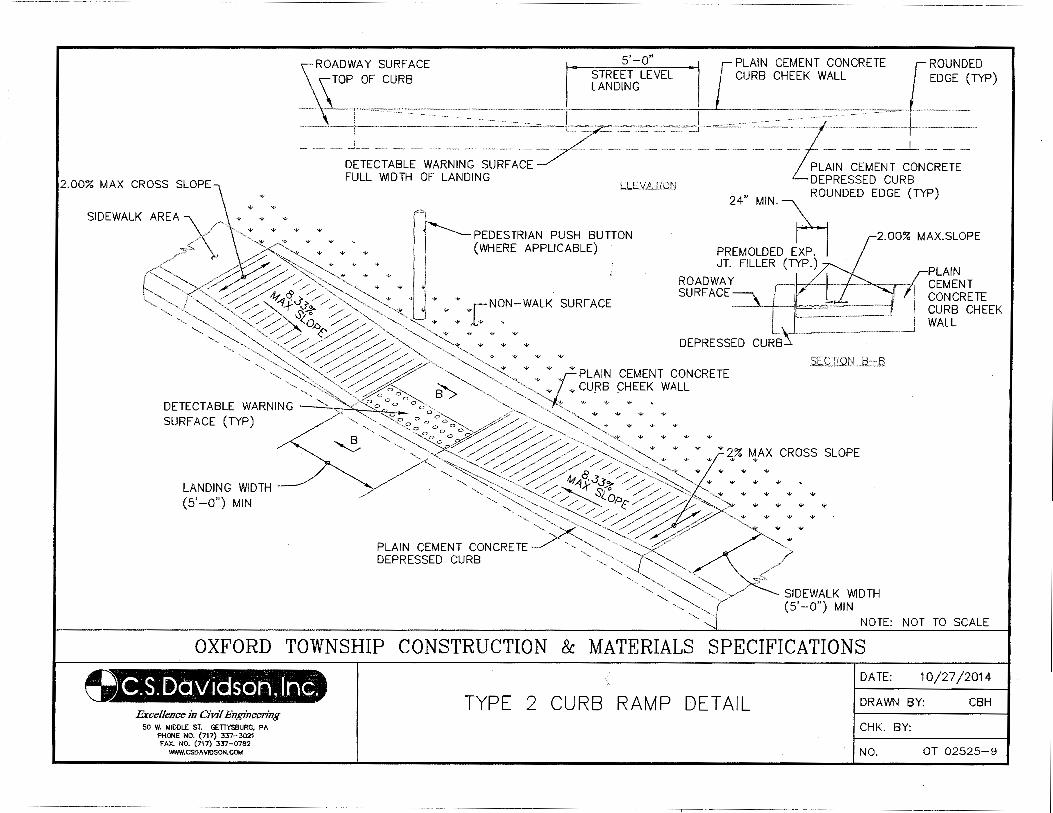
STREET LEVEL SURF ACE LANDING OADWAY
R OF CURB ==l=:;~~~~~~~l-~~=":~:~~--=~=;!. _L -
::- - ENT CONCRETE - CEM CURB
_!_ ARNING SURFACE ELEl(ATION 24" MIN.b DETECT ABLE ; LANDING
5'-0" ,--,---- PLAIN CEMENT CONCRETE
CURB CHEEK WALL ROUNDED EDGE (TYP)
FULL WIDTH
ROUND
2.00% MAX CROSS SLOPE, "•" ~PEDE~~::~p~~;~L~UTI jf.E~LLER (TYP.)
ED EDGE (TYP)
ON OLD ED EXP. ~ '¥ "' I I {WHE .· ROADWAY
SIDEWALK AREA)( '""'"'"' "' , j • SURFACE /~ "' "' ., ' ~ ~~%~ ~ "' "' "' ., * w I J WALK SURFACE --<. ~~~~~ .... i I· ..... ,-NON-('"',,"' ~0 %~/~"'f~.J'.]'/// '»="~ "''Jj _, ,Lw ' ~~ ~'-y/~ ~~ :;::-:: "'~~ ""'- "'"' "' "' "'
,, '-~ '" '-,~/;,/./ ~ "<q,,_ ::/:;/ "' ~-..:_ " " " " " ENT CONCRETE
'.., -..,~ ~ ./__.;/ ~~-;/; / >-.~:::;.:..,_", ~"' "'PLAIN g~~EK WALL "'' .. ,~~~ ~~·" "" :uF~. ""." <::~';::,>:<: ~ 8> -...,,, ~ "'z. " " " E
-...~ '-._:(b::~ ./>-.._~ 'Z ... •,", , •, AX CROSS SLOP C, ~o- 0o~~.///:/"// ......... ~~ ., ., " 2% ~ DETECTABLE ~~RNING -7-... ~~~-:::..~,: •:","," · ,
., ., ~ ~ 0-....:" s,o,.,~ .. " " .. "' .... ':'<:::~. ' ~...?' .. LANDING WIDTH (5'-0") MIN
':::-::~~-::;/ ..
PLAIN CEMENT CONCRETE CURB CHEEK WALL
SURFACE (TY ~ /",'::~~/ //~o_,;.:>~./~~"' "'"'"'., ., "'"'
~'-..,~ / NT CONCRETE "- "':'-.../.. '--.::: ...£, DEWALK "'DTH
PLAIN CSE~DE CURB " , ""'~~~~/( s;,. _ -~o~")~~M~IN~~~N~O~T~T_::::O_:S::.:C_A_LE_I DEPRES "- ..._ ( NOTE1
"'--......., 'I
':J . ATIONS IALS SPECIFIC 1D/27/2D14 MATER DATE! CRH
OXFORD TOWNSHIP CONSTRUCTION &
21-'+t..'' Excellence in Civil Engineering
50 W. MIDDLE ST. GE TIYSSURG, PA PHONE NO. (717) 337-3021 FAX. NO. (717) 337-0782
WWW.CSOAVIOSON.COM
TYPE 2 CURB RAMP DETAIL
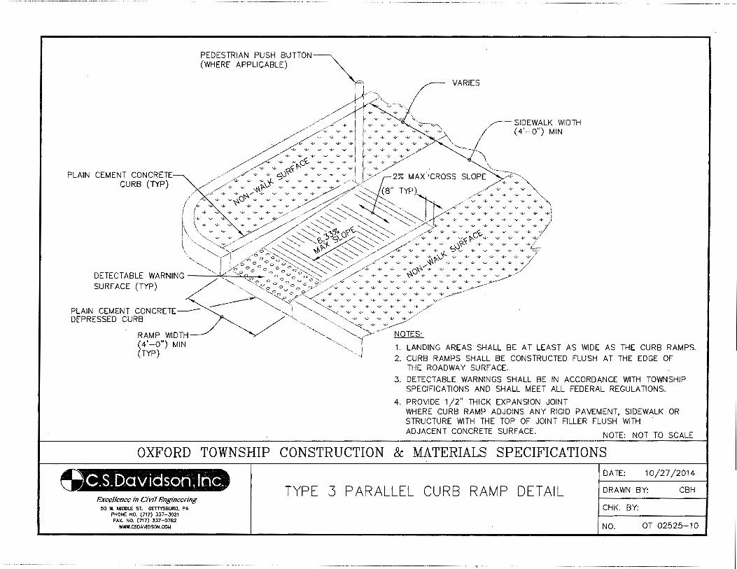
PLAIN CEMENT CONCRETE CURB (TYP)
PEDESTRIAN PUSH BUTTON~ (WHERE APPLICABLE)
I~"'"~ y / ''--
w
"' "' "'
""
"'., r·"" w 7"' / w w w ....v G~ -..l.~ ....v -..v w -w
VARIES
SIDEWALK WIDTH (4'-0") MIN
"' s0 "' "' "' "' "" 2% MAX.'CROSS SLOPE -...._:::;:,~ ~'(~ "" "'"' "'M , ~--w "''f.- "' "'"' "'*/'\~ //"' "'"" "' ~1>-V "' "' "' "' ~/ / (B" T P) / "' "' "' \.,
'V w ~/ w w w ~' W .v'// ' y w w w w w '~ I -.v -.v~O w ""' w w .....,. ~ '4-' w ~ -.,v -4-' "'V
r w """ w w w /-/ ~ ~ -..v """ w ~ w "" -.v . w ' -.v w w ...v ..v /""" - ,~~~ //w "-¥ w v w w -.v w wt
I [-w"' w"' "'~/<~~~~ • • • • • •. •) ~\\"'"-' '+W/, /~~ :J~t~www-l/w-l/ww;Y" I "' "' .... / / "· "'- ~o l?X.. ~ "' * "' ~ "' "' ... "' -.V I \" ""'~"' . "': >·/~·/" "~co:S5s'vo ~""' ~ "' "' "''< ~>-c; "' "' "' "' -:1 ~ "< /// """' :i- ~ // ~ "" w 0~ w "' w w "'y \ "'., ')(/ · ' ~\>- ., "'. ~ ,/' /w w w w S w w w w w w "" I I k./6 0 0~~ "~ / /"' "' w "' ... 'v'f- "' "' * "' "' "' "' ,, ! /a 0 o c. 0 ° ~~ ~ ~ ~ ~ // / ...v w w ~r -w -.v -w -.v w w ..v /
' 1 ~ o 0 0 o 0 ~""-~~~ w ...;.- w w ~w -w o/ ....v ~~ ..v w w/ DETECTABLE WARNING "(~0 -0°::"o :;~/ "'"'"'"' "'}~~"'"'"' "'"'"'"' "'"'"' -: .... ::>,.w/ SURFACE (TYP) /~"" 'Zoo "'o "'a,./~CJ.;r "- "' w "' .., "' .,.. "' "' "' "' ~ ~~ o?-'?C.. ...v w -.v w -.v w -.v w 'l-· w~~-
" "'~of'-, "" -.v w -.v w w w w w y PLAIN CEMENT CONCRETE-~ ',,J ~ "'."' _.,"'..., "'"'"'"' "'"'"' w// DEPRESSED CURB ~ / ~- ', "","' "' "' "" w/
'~'~"'"'~ RAMP WIDTH (4'-0") MIN (TYP)
~~ ~',, ""~~ NOTES:
~""~ 1. LANDING AREAS SHALL BE AT LEAST AS WIDE AS THE CURB RAMPS. 2. CURB RAMPS SHALL BE CONSTRUCTED FLUSH AT THE EDGE OF
THE ROADWAY SURF ACE.
3. DETECTABLE WARNINGS SHALL BE IN ACCORDANCE WITH TOWNSHIP SPECIFICATIONS AND SHALL MEET ALL FEDERAL REGULATIONS.
4. PROVIDE 1 /2" THICK EXPANSION JOINT WHERE CURB RAMP ADJOINS ANY RIGID PAVEMENT, SIDEWALK OR STRUCTURE WITH THE TOP OF JOINT FILLER FLUSH WITH ADJACENT CONCRETE SURFACE. NOTE: NOT TO SCALE
OXFORD TOWNSHIP CONSTRUCTION & MATERIALS SPECIFICATIONS
Excellence in CiviiEngineeriog 50 W. MIDDLE ST. GETIYSBURG, PA
PHONE NO, (717) 337-3021 FAX. NO, (717) 337-0782
WWW.CSDA\IIDSON.COM
TYPE 3 PARALLEL CURB RAMP DETAIL DATE: 10/27/2014
DRAWN BY: CBH
CHK. BY:
NO. OT 02525-10
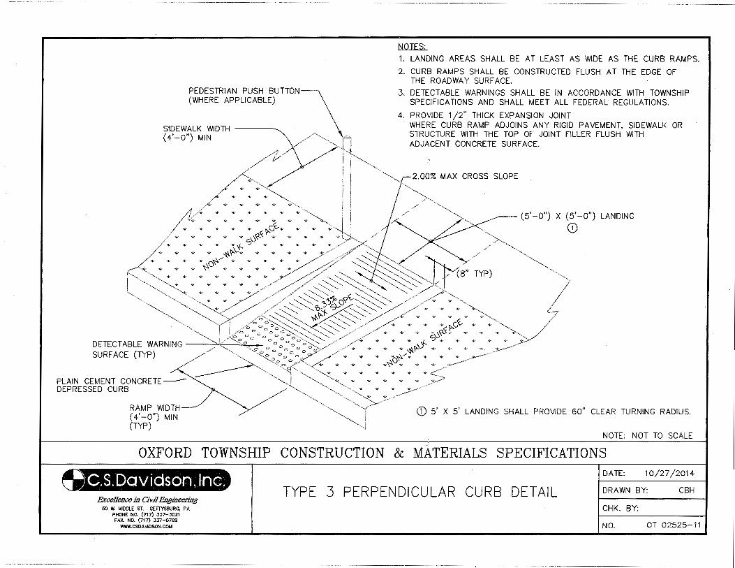
PEDESTRIAN PUSH BUTTON~ (WHERE APPLICABLE)
SIDEWALK WIDTH ~ (4'-o") MIN '\ //~ A
J
"' "' "' "' "'
'W "" w "'
"' "" ".\- """ "' .., "' "' .., 1>-c,X...... "' ...
"' "' "' "" .. 0<(-.x "' "' ~ -.v "" "4-- ""'f.. s ""' ""'"
w ""' "' ""' ~~\)""' ~ "" ~ """'o"A---"' .....
v ~ -v -v ~
w "' "'
"' "'
NOTES:
1. LANDING AREAS SHALL BE AT LEAST AS WIDE AS THE CURB RAMPS.
2. CURB RAMPS SHALL BE CONSTRUCTED FLUSH AT THE EDGE OF THE ROADWAY SURF ACE.
3. DETECTABLE WARNINGS SHALL BE IN ACCORDANCE WITH TOWNSHIP SPECIFICATIONS AND SHALL MEET ALL FEDERAL REGULATIONS.
4. PROVIDE 1 /2" THICK EXPANSION JOINT WHERE CURB RAMP ADJOINS ANY RIGID PAVEMENT, SIDEWALK OR STRUCTURE WITH THE TOP OF JOINT FILLER FLUSH WITH ADJACENT CONCRETE SURFACE.
,-i
2.00% MAX CROSS SLOPE
(5'-0") X (5'-0") LANDING
0
"' ~c,X..."' "' "0<(-.x.
"' "' .J s"' "' DETECTABLE WARNING ,. ., ~1>-\.-'r' .,__ "' SURFACE (TYP) "' t"A.--., "' "'
... ~"' "' .. "' ... PLAIN CEMENT CONCRETEDEPRESSED CURB
~
RAMP WIDTH (4'-0") MIN (TYP)
G) 5' X 5' LANDING SHALL PROVIDE 60" CLEAR TURNING RADIUS.
NOTE: NOT TO SCALE ,f
OXFORD TOWNSHIP CONSTRUCTION & MATERIALS SPECIFICATIONS
9.$.(IDQVi.~s.~(d,:IV'j@~ Excellence in Civil Engineering
50 W. MIDDLE ST. GETTYSBURG, PA PHONE NO. (717) 337-3021 FAX. NO. (717) 337-0782
WWW.CSOAVIOSON.COM
TYPE 3 PERPENDICULAR CURB DETAIL
DATE: 10/27/2014
DRAWN BY: CBH
CHK. BY:
NO. OT 02525-11
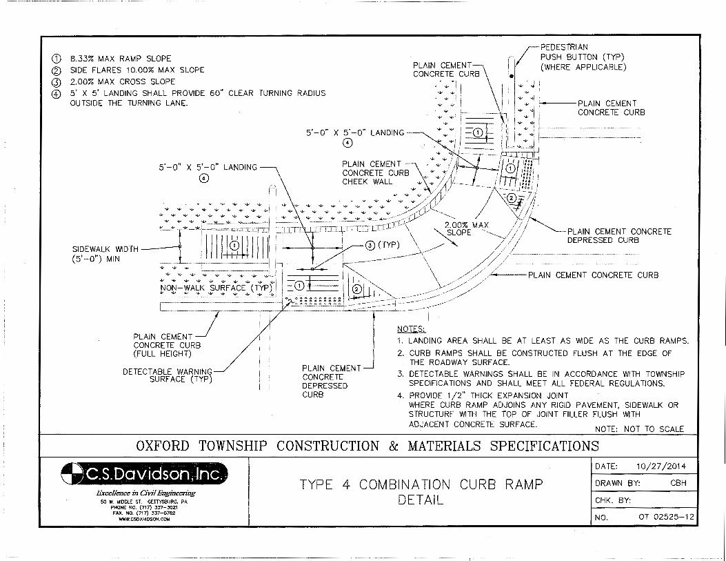
-------------- - ---·- -- ---·· ----- ·--------------~--·----------
CD 8.33% MAX RAMP SLOPE
<l) SIDE FLARES 10.00% MAX SLOPE
@ 2.00% MAX CROSS SLOPE "'
PEDESTRIAN PUSH BUTTON (TYP) (WHERE APPLICABLE)
@) 5' X 5' LANDING SHALL PROVIDE 60" CLEAR TURNING RADIUS OUTSIDE THE TURNING LANE.
w w;
"' t-o---PLAIN CEMENT
"' CONCRETE CURB
5' -0" X 5' -0" LANDING
0
66~1~R~i~~uTRB:\:"' :JA~fml 6fJ!_fl_l __ l CHEEK WALL "' .. j /1/ ___ j I /!!II !
# "' "': "'/~/ f l~··~------·~ 'M --- ~._._) ""-··-·-- -·---1~ ~ ~! ! "" "" w "' ......... ""w "' "' "" "' / /( ~-®-74 "' "' "' "' "' "'~/ -1'/ ..;,J.:J:; /J '-V "" w ..,... ""' ..v -w /"/ /(~/~ \--=!"! ;j
5' -0" X 5' -0" LANDING
0
t: --- ~-=-~;:-.:.: .:!'=:-'-=-,!<·:·~::;1:-rJ~r> ~- / /1/ ,_ ,tliJ __ J L .. LrprUJLLLl- \ 2.00% MAX /I~~
SIDEWALK WIDTH IIIII ~I II II ·-·· _· ....... . ....... . ..... --~-- h\ (TYP)' \ . ""-SLOPE ~y I I PLAIN CEMENT CONCRETE (5'-0") MIN • • • ++t+t _ ·--~~~" ///j DEPRESSED CURB
~~§=f~~~~;ic~~1 1 "''"'"''"~ /~#- ;L~I~~~~~~;:-~~~~~ETE-CURB PLAIN CEMENT CONCRETE CURB (FULL HEIGHT)
DETECTABLE WARNING SURFACE (TYP)
0 : ~ : ;; ::::: 1:::.:;.~·::::-:~:~::::::~==j=:·~::~::::~~r / l
PLAIN CEMENT CONCRETE DEPRESSED CURB
NOTES:
1. LANDING AREA SHALL BE AT LEAST AS WIDE AS THE CURB RAMPS.
2. CURB RAMPS SHALL BE CONSTRUCTED FLUSH AT THE EDGE OF THE ROADWAY SURF ACE.
3. DETECT ABLE WARNINGS SHALL BE IN ACCORDANCE WITH TOWNSHIP SPECIFICATIONS AND SHALL MEET ALL FEDERAL REGULATIONS.
4. PROVIDE 1/2" THICK EXPANSION JOINT WHERE CURB RAMP ADJOINS ANY RIGID PAVEMENT, SIDEWALK OR STRUCTURE WITH THE TOP OF JOINT FILLER FLUSH WITH ADJACENT CONCRETE SURF ACE.
NOTE: NOT TO SCALE
OXFORD TOWNSHIP CONSTRUCTION & MATERIALS SPECIFICATIONS
.Excellence in CiVJ1 Engineering 50 W. MIDDLE ST. GETTYSSURG, PA
PHONE NO. (717) 337-3021 FAX. NO. (717) 337-0782
WWW.CSDAVIOSON.COM
TYPE 4 COMBINATION CURB RAMP DETAIL
DATE: 1 0/27/2014
DRAWN BY: CBH
CHK. BY:
NO. OT 02525-12
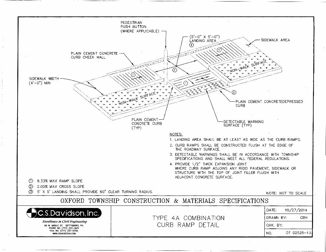
PEDESTRIAN PUSH BUTTON (WHERE A PPLICABLE)
PLAIN CEME l (5'-0" X 5'-0" CURB CHEE~Twi~~CRETE " 0NDING AREA) . -,;><- . -' ~ ; L --- ,.;:;-CC:<;.;-;c,,-:~:,-":-;:;;~~-~ ~','-, ysiDEWALK AREA
\. - -- -- -: :;--r- rt ~,_:r:cr 1 - - "", ~~\:J ~ ~ _ .-- <- -;:;:or'':J-1-" ' 1 "~ ~ ' . . . . . ,<~- ,0- ' • .--' ',. ---""' ' -'"'"'"4 . ~ ' ' ' --- . ' - '
SIDEWALK WIDTH (4'-0") MIN
___ ---"< ~~~ ' ' __ •. --- ----- •• ' .. --·.-- " 0 . ' ® "": ---- -_-___ .---- . .:<: "" "' "' "'-, ,. . ' "' ' ' '"' --- . . . . . "' ~',,~ ~ __ ""-. [ ~--.· ---- ---"""- •. •. • ·,._;.,;:" s~'i<<'S'-. ~ "'• ~ . ------- . --- ,,.. ~---- "·-.: • \:0 • • • • •• "' '· ', .. -k' -- - .• -;;- • J::C-- "';:---~ ' ' • • • • • - ~ --<>
' ' .... ·•· • '.,A • + + ~"' " "' • • ,,• .•<-, .-•' I '-,,'~--..(:,--... "' "' "' _,_* * "' ... "' "' "' "'f"' ,,__.- _ .. - --o-;;"',''--··---~::~---- -·· _ .. ----·· ' ' - • - • - ' ' - -· 0 0 ' . - - -,K;. • • • • • ~ <' •'i<f ,cV • • • -;, , -,; ;,'0 'o
0 o o0 ° 0
. 1'y' , __ .. .-·- · · · · '., '• • • '" ''-" oV • ' ' o o o \ . - ~ -- -
CD 8.33% MAX RAMP SLOPE
@ 2.00% MAX CROSS SLOPE
' '- • • •>'OI'•"r• • • • • ,_..-·>ooooO-o' <>·· ,. "•,. • • • • • ·---·-· .--· .-·> -· ~ '' . . . ·----- .--- . ,---- ' ,,. . . ... -- ---- ---"":' ... "'· .•'"" --· -.- .- .-·" .-. ~~: - : .. : - .-- . PLAIN CEMEN PLAIN CEMENT CURB T CONCRETEDEPRE oo~~cu =
(TYP) RB
NOTES:
DETECTABLE WARNING SURFACE (TYP)
1. LANDING AREA SHALL BE AT LEAST AS WIDE AS THE CURB RAMPS.
2. CURB RAMPS SHALL BE CONSTRUCTED FLUSH AT THE EDGE OF THE ROADWAY SURF ACE.
3. DETECTABLE WARNINGS SHALL BE IN ACCORDANCE WITH TOWNSHIP SPECIFICATIONS AND SHALL MEET ALL FEDERAL REGULATIONS.
4. PROVIDE 1/2" THICK EXPANSION JOINT WHERE CURB RAMP ADJOINS ANY RIGID PAVEMENT, SIDEWALK OR STRUCTURE WITH THE TOP OF JOINT FILLER FLUSH WITH ADJACENT CONCRETE SURFACE.
@ 5' X 5' LANDING SHALL PROVIDE 60" CLEAR TURNING RADIUS. NOTE: NOT TO SCALE
~ OXFORD TOWNSHIP CONSTRUCTION & MATERIALS SPECIFICATIONS
Excellence in Civil Engineering 50 W. MIDDLE ST. GETTYSBURG, PA
PHONE NO. (717) 337-3021 FAX. NO. (717) 337-0782
WWW.CSDAVJOSON.COM
TYPE 4A COMBINATION CURB RAMP DETAIL
DATE: 10/27/2014
DRAWN BY: CBH
CHK. BY:
NO. OT 02525-13
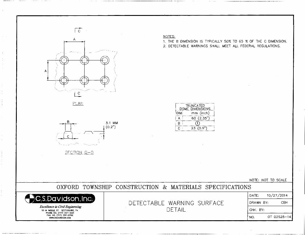
A
lc A
L:..
-n-- 5.1 MM I I 1 (o.2")
.····················~··············· ~===± ! I C I / t i: ----~---- /
' '·
NOTES: 1. THE B DIMENSION IS TYPICALLY 50% TO 65 % OF THE C DIMENSION. 2. DETECTABLE WARNINGS SHALL MEET ALL FEDERAL REGULATIONS.
NOTE: NOT TO SCALE
OXFORD TOWNSHIP CONSTRUCTION & MATERIALS SPECIFICATIONS
Excellence in CiVJ7 Engineering 50 W. MIDDLE ST. GETTYSBURG, PA
PHONE NO. (717) 337-3021 FAX. NO. (717) 337-0782
WWW.CSDAV1DSON.COM
DETECTABLE WARNING SURFACE DETAIL
DATE: 10/27/2014
DRAWN BY: CBH
CHK. BY:
NO. OT 02525-14
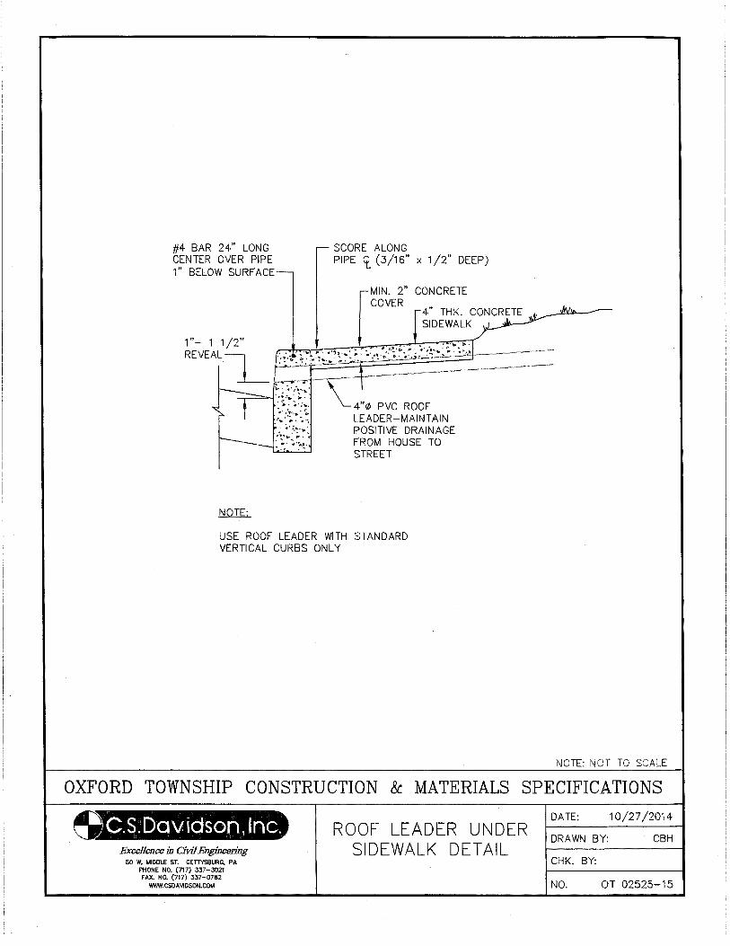
#4 BAR 24" LONG CENTER OVER PIPE 1" BELOW SURF ACE
SCORE ALONG PIPE cr_ (3/16" x 1/2" DEEP)
rMIN. 2" CONCRETE COVER
4" THK. CONCRETE SIDEWALK
1 "- 1 1 /2" . . . ' .... , . REVEAL . .., . .. .. II'·'!·· P· .,·, .... ~··· .... " ~-M---1 ·:~:-\:::.~···.·s~ · .. ~ ... .
). . :,. ,.-........ -· ~~ _,,.-=-l·:t·_~}:~. 4"¢ PVC ROOF
,::·:~~~. LEADER-MAINTAIN : >;.!· .. ~ POSITIVE DRAINAGE ·"~~:.~"~· FROM HOUSE TO ·., . • STREET
NOTE:
USE ROOF LEADER WITH STANDARD VERTICAL CURBS ONLY
NOTE: NOT TO SCALE
OXFORD TOWNSHIP CONSTRUCTION & MATERIALS SPECIFICATIONS
~.s. Dav iason, Inc. Excellence in Civil Engineering
50 W. MIDDLE ST. GETTYS!IURG, PA PHONE NO. (717} 337-3021 FAX. NO. (717) 337-0782
WWW.CSDA\IIDSON.COM
ROOF LEADER UNDER SIDEWALK DETAIL
DATE: 10/27/2014
DRAWN BY: CBH
CHK. BY:
NO. OT 02525-15
02575-1
SECTION 02575
TRENCH PAVING AND RESTORATION
PART 1 GENERAL
1.01 DESCRIPTION
A. The work of this section includes, but is not limited to:
1. Temporary trench paving
2. Permanent trench paving
3. Shoulder restoration
4. Driveway restoration
B. Related work specified elsewhere:
1. Trenching, backfilling, and compacting: Section 02221
2. Bituminous paving and surfacing: Section 02500
3. Plain and reinforced cement concrete: Section 03000
C. Definitions: NONE
D. Applicable Standard Details:
OT 02575-1 Temporary Trench Paving
OT 02575-2 Permanent Trench Paving
1.02 QUALITY ASSURANCE
A. Reference Standards:
1. Pennsylvania Department of Transportation (PennDOT), latest revision:
Publication 408, Specifications
Publication 213, Work Zone Traffic Control Guidelines
Publication 27, Specification for Bituminous Mixtures (Bulletin 27)
Publication 37, Specification for Bituminous Materials (Bulletin 25)
2. American Society for Testing and Materials (ASTM):
D2950 Test Method for Density of Bituminous Concrete in Place by Nuclear Method
3. Pennsylvania Code
Title 67 Transportation, Chapter 459, Occupancy of Highways by Utilities
B. Inspections:
1. Inspection by the Municipality will, at a minimum, be made of the subgrade prior to placement of the
base course, and of the base course prior to placement of the binder surface.
1.03 SUBMITTALS
A. Certificates:
02575-2
1. Submit certification from bituminous and aggregate suppliers attesting that materials conform to
Publication 408. Submit bituminous concrete mix design for approval. Provide PennDOT
certifications (CS-4171) with each load delivered to the job site.
1.04 JOB CONDITIONS
A. Control of Traffic:
1. Take measures to control traffic during paving operations. Do not allow traffic on newly paved areas
until adequate stability and adhesion have been attained and the material has cooled to 140 F or less.
2. Employ Traffic Control Guidelines measures in accordance with Publication 213.
B. Protection of Adjacent Areas:
1. Restore existing surface outside the limits of the work, that has been damaged by the Contractor's
operations, to its original condition at the expense of Contractor.
C. Concrete Testing: Section 03000.
PART 2 PRODUCTS
2.01 CONCRETE
A. As specified in Section 03000.
B. For driveway restoration, use air-entrained, PennDOT Class HES (High Early Strength) with 3-day
compressive strength of 3,300 psi. (28-day compressive strength of 3,750 psi, as per Section 704 of Pub.
408).
2.02 BITUMINOUS MATERIALS AND AGGREGATES
A. All bituminous materials and aggregates used in base course construction, paving, and resurfacing are
designated in these specifications by, and shall conform to, the applicable portions of the Publication 408
Specifications. See descriptions in Sections 02230 and 02500.
PART 3 EXECUTION
3.01 TEMPORARY TRENCH PAVING
A. Place temporary paving immediately upon completion of trench backfilling. Unpaved trenches shall not
remain unpaved longer than five working days after backfilling, nor over weekends and holidays.
B. Shape and compact subgrade material, then place and compact base course to the required thickness. Apply
tack coat to vertical trench sides, in accordance to Publication 408, Section 460.
C. Place temporary paving material. Compact to required minimum thickness with trench roller having a
minimum 300 pounds pressure per inch-width of compaction.
D. Continuously maintain temporary paving.
02575-3
3.02 PERMANENT TRENCH PAVING
A. For Bituminous Surface Course (Trench) saw cut existing paving in accordance with PA Code 67, Chapter
459. Remove temporary paving material.
B. Construct permanent base and surface courses to the required compacted thicknesses shown in the Backfill
and Surface Restoration Requirements Table, and in accordance with Publication 408 Specifications. In
State Highways, construct permanent paving in accordance with Highway Occupancy Permit requirements.
C. Maintain permanent paving throughout the contract maintenance period.
3.03 BITUMINOUS OVERLAY
A. See Section 02500.
3.04 SHOULDER RESTORATION
A. Restore shoulders as directed by the Municipality. In State Highways, restore in accordance with Highway
Occupancy Permit requirements.
3.05 DRIVEWAYS
A. Trim concrete and bituminous driveway surfaces to remove damaged areas. Saw or cut straight joint lines
parallel to the centerline of the trench. Cut offsets at right angles to the trench centerline.
B. Restore existing concrete driveways with a 6" layer of concrete reinforced with WWF 6 x 6 - W2.9 x W2.9
(6 ga.) wire mesh, placed 2" from top surface. See Section 03000.
C. Restore existing bituminous driveways in kind; minimum 1½" layer wearing course over 6" layer of select
granular material (No. 2A stone).
D. Restore earth driveways with a 6" layer of select granular material (No. 2A stone).
E. Restore stone or gravel driveways in kind; minimum 6" layer of select granular material (2A stone).
F. Restore brick driveways with like bricks placed on a 4" thick wet sand bed. Place bricks in like pattern and
spacing.
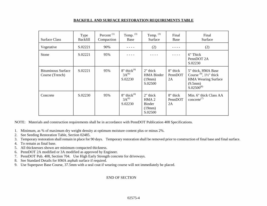
02575-4
BACKFILL AND SURFACE RESTORATION REQUIREMENTS TABLE
Surface Class
Type
Backfill
Percent
(1)
Compaction
Temp.
(3)
Base
Temp.
(3)
Surface
Final
Base
Final
Surface Vegetative
S.02221
90%
- - - -
(2)
- - - -
(2)
Stone
S.02221
95%
- - - -
- - - -
- - - -
6" Thick
PennDOT 2A
S.02230 Bituminous Surface
Course (Trench)
S.02221
95%
8" thick
(4)
3A(6)
S.02230
2" thick
HMA Binder
(19mm)
S.02500
8" thick
PennDOT
2A
5" thick, HMA Base
Course (9)
, 1½" thick
HMA Wearing Surface
(9.5mm)
S.02500(8)
Concrete
S.02230
95%
8" thick
(4)
3A(6)
S.02230
2" thick
HMA 2
Binder
(19mm)
S.02500
8" thick
PennDOT
2A
Min. 6" thick Class AA
concrete(7)
NOTE: Materials and construction requirements shall be in accordance with PennDOT Publication 408 Specifications.
1. Minimum, as % of maximum dry weight density at optimum moisture content plus or minus 2%.
2. See Seeding Restoration Table, Section 02485.
3. Temporary restoration shall remain in place for 90 days. Temporary restoration shall be removed prior to construction of final base and final surface.
4. To remain as final base.
5. All thicknesses shown are minimum compacted thickness.
6. PennDOT 2A modified or 3A modified as approved by Engineer.
7. PennDOT Pub. 408, Section 704. Use High Early Strength concrete for driveways.
8. See Standard Details for HMA asphalt surface if required.
9. Use Superpave Base Course, 37.5mm with a seal coat if wearing course will not immediately be placed.
END OF SECTION
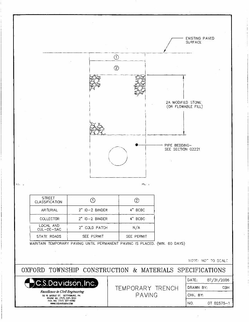
STREET CD CLASSIFICATION
ARTERIAL 2" ID-' 2 BINDER
COLLECTOR 2" ID-2 BINDER
LOCAL AND 2" COLD PATCH CUL-DE-SAC
STATE ROADS SEE PERMIT
EXISTING PAVED SURFACE
2A MODIFIED STONE (OR FLOWABLE FILL)
•--+--- PIPE BEDDING-SEE SECTION 02221
@
4" BCBC
4" BCBC
N/A
SEE PERMIT
MAINTAIN TEMPORARY PAVING UNTIL PERMANENT PAVING IS PLACED. (MIN. 60 DAYS)
NOT TO SCALE
OXFORD TOWNSHIP CONSTRUCTION & MATERIALS SPECIFICATIONS
O.S. Davids om, I me. Excellence in Civil Engineering
50 W. MIDDLE ST. GETTYSBUR~, PA PHONE NO. (717) 337-3021 FAX. NO. (717) 337-0782
WWW.CSOAVIDSON.COM
TEMPORARY TRENCH PAVING
DATE: 07/31 /2006
DRAWN BY: CBH
CHK. BY:
NO. OT 02575-1
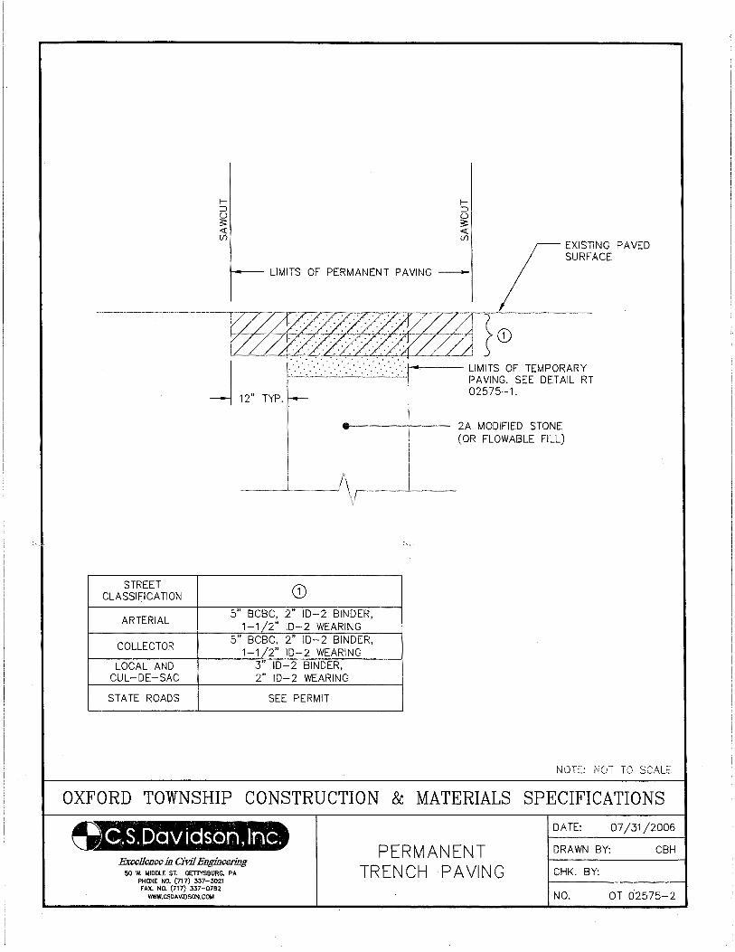
I::>
~ <( (/)
LIMITS OF PERMANENT PAVING -
. . . . . . .. . . . . . . . . ·. · ·. ·. · ·. ·. · ·. ·. · ·. ·. · ·. ·. · ·. ·. ·. ·1--c---- LIMITS OF TEMPORARY
- 12" TYP.
PAVING. SEE DETAIL RT 02575-1.
e-------'1---- 2A MODIFIED STONE (OR FLOWABLE FILL)
STREET CLASSIFICATION
ARTERIAL
COLLECTOR
LOCAL AND CUL-DE-SAC
STATE ROADS
CD 5" BCBC, 2" ID- 2 BINDER,
1-1 2" ID-2 WEARING 5" BCBC, 2" ID-2 BINDER,
1-1 2" ID-2 WEARING 3" ID-2 BINDER, 2" ID-2 WEARING
SEE PERMIT
NOTE: NOT TO
OXFORD TOWNSHIP CONSTRUCTION & MATERIALS SPECIFICATIONS
~.S.Dcrviason,ln~. Excellence in Civil Engineering
50 W. MIDDLE ST. GETTYSBURG, PA PHONE NO. (717) 337-302.1 FAX. NO. (717) 337-0782
WWW.CSDAVIDSON.COI.I
PERMANENT TRENCH PAVING
DATE: 07/31/2006
DRAWN BY: CBH
CHK. BY:
NO. OT 02575-2
02581-1
SECTION 02581
CONDUIT FOR UNDERGROUND UTILITIES
PART 1 GENERAL
1.01 DESCRIPTION
A. The work of this section includes, but is not limited to, installation of conduits for:
1. Natural gas transmission
2. Underground electrical power transmission
3. Underground telephone and cable TV
B. Related Work Specified Elsewhere:
1. Trenching, backfilling and compacting: Section 02221
C. Definitions: NONE
D. Applicable Standard Details: NONE
1.02 QUALITY ASSURANCE
A. American Society for Testing and Materials (ASTM):
D1785 Specifications for Poly (Vinyl Chloride) (PVC) Plastic Pipe, Schedule 40, 80, and 120
D2241 Specifications for Poly (Vinyl Chloride) (PVC) Plastic Pipe (SDR-PR)
D2321 Recommended Practice for Underground Installation of Flexible Thermoplastic Sewer Pipe
D2564 Specifications for Solvent Cements for Poly (Vinyl Chloride) (PVC) Plastic Pipe and Fittings
D2855 Recommended Practice for Making Solvent-Cemented Joints with Poly (Vinyl Chloride) (PVC)
Plastic Pipe and Fittings
D2729 Specifications for Poly (Vinyl Chloride) (PVC) Sewer Pipe and Fittings
B. Materials contaminated with gasoline, lubricating oil, liquid or gaseous fuel, aromatic compounds, paint
solvents, paint thinner, or acid solder will be rejected.
1.03 SUBMITTALS: Section not utilized
1.04 JOB CONDITIONS: See Section 02221.
1.05 PRODUCT DELIVERY, STORAGE AND HANDLING
A. Delivery and Handling:
1. During loading, transporting and unloading, exercise care to prevent damage to materials.
2. Do not drop pipe or fittings. Avoid shock or damage at all times.
3. Take measures to prevent damage to the exterior surface or internal lining of the pipe.
B. Storage:
1. Do not stack pipe higher than recommended by the pipe manufacturer.
02581-2
2. Store PVC pipe and fittings in a cool, dry location out of direct sunlight and not in contact with
petroleum products.
PART 2 - PRODUCTS
2.01 POLY (VINYL CHLORIDE) (PVC) UTILITY CONDUIT
A. Natural Gas:
1. Main line conduits - three inch (3") diameter and larger shall meet the requirements of ASTM D2729.
Joints shall be solvent cement.
2. Service line conduits - two and one-half inch (2½") diameter and smaller shall meet the requirements of
ASTM D1785 (Schedule 40). Joints shall be solvent cement.
B. Telephone, Electric and Cable TV:
1. Main line conduits - three inch (3") diameter and larger shall meet the requirements of ASTM D2729.
Joints shall be solvent cement.
2.02 WARNING TAPE
A. Metallic warning tape, six inch (6") minimum width, printed with "CAUTION BURIED UTILITY LINE
BELOW" or similar. Tape may be provided by utility company or furnished by the installing contractor
and approved by utility. Materials shall meet requirements of U.S. DOT, office of Public Safety.
PART 3 - EXECUTION
3.01 EXCAVATION
A. Depth of Excavation
1. Natural Gas Line:
a. Excavate main line trenches to a minimum depth of 36". Grade for the invert of the conduit
plus that excavation necessary for placement of bedding material. During Street construction,
prior to installation of the stone base course, conduits shall be installed at all proposed crossings.
Conduits shall extend a minimum of two feet (2') beyond the curb line where curbs are proposed
or a minimum of five feet (5') beyond the paving where no curbs are proposed to be installed.
b. Excavation for service lines shall be as nearly perpendicular to the street centerline as possible
and shall be a minimum of twenty-four inches (24") deep plus that excavation necessary for
placement of bedding material. A minimum of two (2) service line conduits shall be placed for
each lot which will require a street crossing, prior to installation of the stone base course.
Location of the service line conduits shall be coordinated with the local gas supplier. With
written authorization from the gas supplier, the number of conduits may be reduced to one (1).
In any event, no open cut trenching for installation of gas services will be allowed after
installation of the stone base course.
02581-3
2. Electric Conduits:
a. Excavate main line trenches to a minimum depth of twenty-four inches (24") plus that
excavation necessary for placement of bedding material. During street construction and prior to
installation of the stone base course, conduits shall be installed at all proposed crossings.
Conduits shall extend a minimum of two feet (2') beyond the curb line where curbs are proposed
or a minimum of five feet (5') beyond the paving where no curbs are proposed to be installed.
3. Telephone and Cable TV:
a. Excavate main line trenches to a minimum depth of twenty-four inches (24") plus that
excavation necessary for placement of pipe bedding material. During street construction and
prior to installation of the stone base course, conduits shall be installed at all proposed crossings.
Conduit shall extend a minim of two feet (2') beyond the curb line where curbs are proposed or a
minimum of five feet (5') beyond the paving where no curbs are proposed to be installed.
B. Where unsuitable bearing material is encountered in the trench bottom, continue excavation until the
unsuitable material is removed, solid bearing is obtained or can be established, or concrete cradle can be
placed. If no concrete cradle is to be installed, refill the trench bottom to required conduit grade, minus six
inches (6") for bedding, with Penn DOT 2RC aggregate.
C. Width of Excavation:
1. Excavate main line and service trenches to a maximum width of twenty-four inches (24").
D. Lay conduit to a true uniform line with a barrel of the conduit resting solidly in bedding material
throughout its length. Excavate recesses in bedding material to accommodate joints. Do not subject the
conduit to a blow or shock to achieve solid bearing or grade.
E. Lay section of conduit in such a manner as to form a closed concentric joint with the adjoining section and
to avoid offsets in the conduit.
F. Clean and inspect each section of the conduit before joining. Assemble to provide tight, flexible joints that
permit movement caused by expansion, contraction, and ground movement. If unusual joining resistance is
encountered or if the conduit cannot be fully inserted into the bell, disassemble joint, inspect for damage,
reclean joint components, and reassemble joint.
G. Assemble joints in accordance with recommendations of the manufacturer.
1. Solvent cemented joints:
2. Camfer and deburr conduit. Clean socket and plain end. Measure and mark the socket depth on the
outside of the conduit.
3. Apply primer to inside socket surface using a scrubbing motion to ensure penetration. Repeated
applications may be necessary. Soften surface of male end of conduit to depth of fitting socket by
applying a liberal brush coat of primer. Do not pour primer on. Assure entire surface is well softened.
4. Repeat application of primer to inside socket surface, then apply cement to conduit while surfaces are
still wet with primer. Apply cement uniformly taking care to keep excess cement out of socket.
02581-4
5. Immediately after applying the last coat of cement to the conduit, and while both the inside socket
surface and outside conduit surface are soft and wet, forcefully seat the conduit into the socket. Turn the
conduit ¼ turn during assembly to distribute the cement evenly. Assembly should be completed within
twenty (20) seconds after the last application of cement. Insert conduit with a steady, even motion. Do
not use hammer blows.
6. Hold joint in place until cement has set. Wipe excess cement from the conduit.
H. Place sufficient compacted bedding and backfill on each section of conduit, as it is laid, to hold firmly in
place.
I. Keep trenches and excavations free from water during construction.
J. When work is not in progress, at the end of each day, and at the end of each conduit run, securely plug open
ends of conduit to prevent trench water, earth, and other substances from entering the conduit.
3.02 CONDUIT BEDDING AND BACKFILL
A. All conduits must be surrounded with a minimum of six inches (6") of stone dust (AASHTO#10) on top,
bottom and each side.
B. For specific higher voltage lines, place 6" concrete encasement as directed by the utility company.
3.03 DETECTABLE WARNING TAPE FOR ELECTRIC AND NATURAL GAS CONDUITS
A. The warning tape shall be installed twelve inches (12") below the finished ground or street surface. Materials
shall meet the requirements of U. S. Department of Transportation, Office of Pipeline Safety, Code for
pressure piping.
END OF SECTION
02601-1
SECTION 02601
MANHOLES
PART 1 GENERAL
1.01 The work of this section includes the installing, repairing, and testing of sanitary sewer manholes.
1.02 All sanitary sewer manholes in the Township are owned and maintained by the New Oxford Municipal
Authority.
PART 2 PRODUCTS
2.01 All materials shall be in accordance with the requirements of the New Oxford Municipal Authority.
PART 3 EXECUTION
3.01 All work shall be performed in accordance with the requirements of the New Oxford Municipal Authority.
3.02 Refer to Section 02221 – Trenching, Backfilling and Compacting
END OF SECTION
02602-1
SECTION 02602
STORM INLETS, CATCH BASINS, ENDWALLS
PART 1 GENERAL
1.01 DESCRIPTION
A. The work of this section includes, but is not limited to:
1. Storm drainage inlets
2. Storm drainage catch basins
3. Storm drainage pipe endwalls
4. Pipe culvert end sections
B. Related work specified elsewhere:
1. Trenching, backfilling and compacting: Section 02221
2. Soil erosion and sediment pollution control: Section 02270
3. Finish grading, seeding and sodding: Section 02485
4. Bituminous paving and surfacing: Section 02500
5. Manholes: Section 02601
6. Storm drain pipe: Section 02618
7. Plain and reinforced cement concrete: Section 03000
8. Cement concrete for utility construction: Section 03050
C. Definitions: NONE
D. Applicable Standard Details: OT- 02602-1 Inlet/ Storm Pipe Installation Detail
1.02 QUALITY ASSURANCE
A. Reference Standards:
1. Pennsylvania Department of Transportation (PennDOT), latest revision:
Publication 408, Specifications
Publication 72M, Standards for Roadway Construction
2. American Society for Testing and Materials (ASTM):
A36 Specification for Carbon Structural Steel
A47 Specification for Ferritic Malleable Iron Castings
A48 Specification for Gray Iron Castings
A185 Specification for Steel Welded Wire Fabric for Concrete Reinforcement
A536 Specification for Ductile Iron Castings
A615 Specification for Deformed and Plain Billet-Steel Bars for Concrete
Reinforcement
C32 Specification for Sewer and Manhole Brick (made from clay or shale)
C270 Specification for Mortar for Unit Masonry
3. Pennsylvania Code
Title 67, Transportation, Chapter 459, Occupancy of Highway by Utilities.
02602-2
1.03 SUBMITTALS
A. Certificates:
1. Submit certification from material suppliers attesting that materials provided meet or exceed
specification requirements.
B. Shop Drawings:
1. Submit detailed Shop Drawings, including reinforcing steel details.
C. Submit concrete mix designs, certified results of compressive strength tests, certified field tests and copies
of batch slips for all cast-in-place inlets, catch basins or endwalls.
1.04 JOB CONDITIONS: Section not utilized.
1.05 PRODUCT DELIVERY, STORAGE AND HANDLING
A. Precast Concrete Units:
1. After fabrication and curing, transport the units to the job site. Protect until required for installation.
2. Handle to avoid damage to surfaces, edges and corners and to avoid creation of stresses within the units.
B. Inspections
1. Inspection by the Municipality will, at a minimum, be made of materials upon delivery to the job site; of
the subgrade, prior to construction or placement; and of the completed structure, prior to backfill.
2. Precast cement concrete products shall be subject to rejection for failure to conform with these
specifications or if any one of the following conditions is noted:
a. Fractures or cracks passing through the wall, except for a single end crack that does not exceed the
depth of the joint.
b. Defects that indicate incorrect proportioning, mixing, and molding.
c. Surface defects larger than ½" diameter indicating honey-combed or open texture.
d. Damaged or cracked ends, where such damage would prevent making a satisfactory joint.
3. Concrete Testing (For Cast-In-Place Work): Section 03000.
PART 2 PRODUCTS
2.01 MATERIALS
A. Crushed Stone Subbase:
1. AASHTO No. 57 or No. 8, Type C, Section 703.2, Publication 408 Specifications. Do not use slag or
cinders.
B. Brick: ASTM C32 Grade SS, solid.
C. Masonry Mortar: ASTM C270, Type S.
02602-3
D. Malleable Iron Castings: ASTM A47, Grade 35018, Domestic.
E. Ductile Iron Castings: ASTM A536, Grade 60-40-18, Domestic.
F. Structural Grade Carbon Steel: ASTM A36.
G. Cast-in-Place Cement Concrete: Section 03050.
H. Cast Gray Iron Castings: ASTM A48.
2.02 FABRICATIONS
A. Precast Cement Concrete Units:
1. Comply with the requirements of Section 714, Publication 408 Specifications. Concrete shall be Class
AA, unless otherwise specified.
2. All reinforcing shall comply with the requirements of Publication 72M.
3. 6' inlets shall be similar in all respects to standard inlets except that the longitudinal dimension shall be
increased by 24".
4. Modified boxes (PennDOT Type 1, 2 or 3, Modified Type I or Modified Type II) shall have reinforced
cover adjustment slabs in accordance with Details in Publication 72M.
B. Pipe Culvert End Sections:
1. Concrete or Metal - Comply with the requirements of, Publication 72M, RC-33.
2. Polyethylene end sections shall have smooth interior and be anchored at the flared end.
C. Inlet Grates:
1. Comply with the requirements of Publication 72M, RC-34 PennDOT approved diagonal or bicycle safe
grates only.
2. 6' inlet grates shall be similar in all respects to standard inlet grates except that the longitudinal
dimension shall be increased by 24".
3. Inlet grates in traffic areas shall be capable of handling HS-25 loading.
4. Welded structural steel grates and frames shall be coated with bituminous paint. All iron castings shall
be furnished unpainted.
D. Adjustments
1. Precast Cement Concrete Grade Adjustment Risers: Risers shall be cast from 4000 psi concrete
(28-day compressive strength), shall be a minimum of 2" thick, and shall be reinforced in accordance
with ASTM A478.
2. Brick or block adjustments are not permitted.
3. Infra-Riser adjustment rubber rings manufactured by East Jordan Iron Works, East Jordan, Michigan or
approved equal, may be substituted for concrete rings if approved by the ENGINEER.
E. Outlet Structures
02602-4
1. Precast concrete or cast-in-place concrete in accordance with Article 2.02.A.
2. Construct outlet structures to dimensions shown on the drawings.
PART 3 EXECUTION
3.01 EXCAVATION
A. Excavate as specified in Section 02221.
B. Excavate at location marked in the field.
C. Excavate to the required depth and grade for the bottom of the unit plus that excavation necessary for
placement of base material.
3.02 CONSTRUCTION
A. Construct inlets and catch basins of either precast cement concrete sections or of cast-in-place cement
concrete, and of the type indicated on the drawings.
1. Place precast units on a minimum 4" compacted crushed stone base.
2. Construct cast-in-place units on 4” crushed aggregate base.
3. Unless units are cast-in-place, use precast cement concrete grade adjustment risers or Infra-Risers to
adjust to grade, minimum thickness – 2”. Bricks, concrete block, etc. are not allowed. Mortar in
place.
4. Place bicycle safe grates in all paved (present or future) areas.
B. Construct endwalls to the dimensions and design indicated on Standard Drawing RC-31M, Publication
72M, and of the type shown on the drawings. Construct endwalls of monolithically cast reinforced
concrete.
C. Do not permit pipes to project more than 2" into inlets. Do not expose end of pipe through faces of
endwalls. Complete pipe to inlet, headwall, endwall or other concrete structures in accordance with Detail
2602-1. Do not backfill until verified by Township Representative.
D. Where indicated on the drawings, provide pipe culvert end sections of the design and dimensions of
Standard Drawing RC-33M, Publication 72M.
E. Install polyethylene end sections in accordance with manufacturer’s instructions, bedded and anchored as
required.
F. Construct basin outlet structures with inverts, grates and openings at the required elevations shown on the
drawings. Connect to new or existing outlet pipes, relaying or adding pipe as needed to meet the structure.
3.03 BACKFILLING
A. Backfill structures only after inspection by the Municipality.
B. Perform backfilling and compaction as specified in Section 02221.
3.04 DISPOSAL OF EXCAVATED MATERIAL: Section 02221.
02602-5
3.05 RESTORATION OF SURFACE AREAS
A. Restore paved areas in accordance with Section 02575.
B. Restore unpaved surfaces as specified in Section 02221.
END OF SECTION
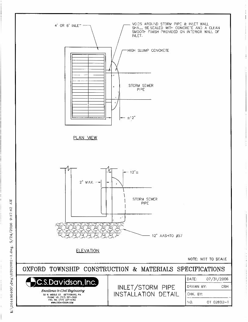
4' OR 6' INLET
PLAN VIEW
ELEVATION
\ I I
VOIDS AROUND STORM PIPE & INLET WALL SHALL BE SEALED WITH CONCRETE AND A CLEAN SMOOTH FINISH PROVIDED ON INTERIOR WALL OF INLET.
HIGH SLUMP CONCRETE
STORM SEWER PIPE
±12"
STORM SEWER PIPE
NOTE: NOT TO SCALE
OXFORD TOWNSHIP CONSTRUCTION & MATERIALS SPECIFICATIONS
C.S.Davidson, Inc. Excellence in Civil Engineering
50 W. MIDDLE ST. GETTYSBURG, PA PHONE NO. (717) 337-3021 FAX. NO. (717) 337-0782
WWW.CSDAVIDSON.COM
INLET /STORM PIPE INSTALLATION DETAIL
DATE: 07/31/2006
DRAWN BY: CBH
CHK. BY:
NO. OT 02602-1
02610-1
SECTION 02610
SANITARY SEWER PIPE
PART 1 GENERAL
1.01 The work of this section includes the installing, repairing, and testing of sanitary sewer pipe.
1.02 All sanitary sewer pipe in the Township are owned and maintained by the New Oxford Municipal Authority.
PART 2 PRODUCTS
2.01 All materials shall be in accordance with the requirements of the New Oxford Municipal Authority.
PART 3 EXECUTION
3.01 All work shall be performed in accordance with the requirements of the New Oxford Municipal Authority.
3.02 Refer to Section 02221 – Trenching, Backfilling and Compacting
END OF SECTION
02615-1
SECTION 02615
WATER MAINS
PART 1 GENERAL
1.01 The work of this section includes the installing, repairing and testing of water mains.
1.02 All public water mains in the Municipality are owned and maintained by the York Water Company or the New
Oxford Municipal Authority.
PART 2 PRODUCTS
2.01 All materials shall be in accordance with the requirements of the York Water Company or the New Oxford
Municipal Authority.
PART 3 EXECUTION
3.01 All work shall be performed in accordance with the requirements of the York Water Company or the New
Oxford Municipal Authority.
3.02 Refer to Section 02221- Trenching, Backfilling, and Compacting.
END OF SECTION
02618-1
SECTION 02618
STORM DRAIN PIPE
PART 1 GENERAL
1.01 DESCRIPTION
A. The work of this section includes, but is not limited to:
1. Storm sewer pipelines
2. Pavement base drains and subdrains
B. Related work specified elsewhere:
1. Boring and jacking: Section 02150
2. Trenching, backfilling and compacting: Section 02221
3. Soil erosion and sediment pollution control: Section 02270
4. Finish grading, seeding and sodding: Section 02485
5. Trench paving and restoration: Section 02575
6. Manholes: Section 02601
7. Storm inlets, catch basins, endwalls: Section 02602
8. Cement concrete for utility construction: Section 03050
C. Definitions:
1. Polyethylene pipe Type C - full circular cross-section with corrugated surface both inside and outside.
2. Polyethylene pipe Type S - full circular cross-section with outer corrugated pipe wall and smooth
inner wall.
D. Applicable Standard Details: NONE
1.02 QUALITY ASSURANCE
A. Reference Standards:
1. Pennsylvania Department of Transportation (PennDOT), latest revision:
Publication 408, Specifications
Publication 72M, Standards for Roadway Construction
2. American Society for Testing and Materials (ASTM):
C76 Specification for Reinforced Concrete Culvert, Storm Drain, and Sewer Pipe
C507 Specification for Reinforced Concrete Elliptical Culvert, Storm Drain, and Sewer Pipe
D2241 Specification for Poly(Vinyl Chloride)(PVC) Pressure Rated Pipe (SDR series)
D2321 Practice for Underground Installation of Thermoplastic Pipe for Sewers and other
Gravity-Flow Applications.
F405 Specification for Corrugated Polyethylene (PE) Tubing and Fittings
F667 Specification for Large Diameter Corrugated Polyethylene Tubing and Fittings
3. American Association of State Highway Transportation Officials (AASHTO):
M36 Metallic (zinc or aluminum) coated corrugated steel culverts and underdrains
02618-2
M246 Precoated galvanized steel sheet for culverts and underdrains
M252 Corrugated Polyethylene Drainage Tubing
M278 Class PS50 Polyvinyl Chloride (PVC) Pipe
M294(and MP6-95) Corrugated Polyethylene Pipe, 12" to 36" Diameter
1.03 SUBMITTALS
A. Certificates:
1. Submit two copies of manufacturer's certification attesting that the pipe, fittings, and joints meet or
exceed specification requirements.
B. Manufacturer's Literature:
1. Submit two copies of the manufacturer's recommendations on installation, handling, and storage of
materials.
1.04 JOB CONDITIONS: Section not utilized.
1.05 PRODUCT DELIVERY, STORAGE, AND HANDLING
A. During loading, transporting, and unloading, exercise care to prevent damage to materials.
B. Do not drop pipe or fittings. Avoid shock or damage at all times.
C. Do not place materials on private property without written permission from the property owner.
PART 2 PRODUCTS
2.01 CORRUGATED POLYETHYLENE PIPE
A. Tubing and Fittings - 3" to 6"
1. AASHTO M252
2. ASTM F405
B. Pipe and Fittings - 12" to 48"
1. Integrally formed smooth interior.
2. AASHTO M294 and MP6-95
3. ASTM F667
C. Pavement Base Drains - 4", 6"
(1) AASHTO M304
2.02 REINFORCED CONCRETE PIPE
A. Pipe and Fittings:
1. ASTM C76, Minimum Class II
B. Joints:
1. Tongue and groove or bell and spigot.
02618-3
2.03 ELLIPTICAL REINFORCED CONCRETE PIPE
A. Pipe:
1. ASTM C507, Minimum Class HE-A or VE-II.
2.04 CORRUGATED GALVANIZED STEEL PIPE AND PIPE ARCH
A. Shall not be utilized unless specifically approved by Municipality.
2.05 POLY (VINYL CHLORIDE) PIPE 3" TO 6"
A. Pipe and Fittings
1. AASHTO M278
2. ASTM D3034
PART 3 EXECUTION
3.01 PREPARATION
A. Perform trench excavation and associated work as specified in Section 02221.
B. Provide pipe bedding (Type III or IV) as specified in Section 02221. Place aggregate so that the pipe can be
laid to the required tolerances.
3.02 LAYING PIPE IN TRENCHES
A. Give ample notice to the Municipality in advance of pipe laying operations, minimum twenty-four hours.
B. Lower pipe into trench using handling equipment designed for the purpose to assure safety of personnel and
to avoid damage to pipe. Do not drop pipe.
C. Lay pipe proceeding upgrade with the bell or groove pointing upstream.
D. Lay pipe to a true uniform grade with the barrel of the pipe resting solidly in bedding material throughout its
length. Excavate recesses in bedding material to accommodate joints, fittings and appurtenances. Do not
subject pipe to a blow or shock to achieve solid bearing or grade.
E. Lay each section of pipe in such a manner as to form a close concentric joint with the adjoining section and
to avoid offsets in the flow line.
F. Clean and inspect each pipe and fitting before joining. Align pipe with previously laid sections. Assemble
to provide tight, flexible joints that permit movement caused by expansion, contraction, and ground
movement. Assemble joints in accordance with the pipe manufacturer's instructions.
G. Check each pipe installed as to line and grade in place. Correct deviation from line and grade immediately.
A deviation from the designed line or grade as shown on the drawings will be cause for rejection.
H. Place and compact sufficient backfill to hold each section of pipe firmly in place as the pipe is laid.
3.03 BACKFILLING TRENCHES
A. Backfill pipeline trenches only after examination of pipe by the Municipality.
B. Backfill and compact trenches as specified in Section 02221.
02618-4
3.04 PAVEMENT BASE DRAINS AND PIPE UNDERDRAINS
A. Construct drains of the size and type indicated on the drawings in accordance with the requirements set forth
in Section 6l0, Publication 408 Specifications and as shown on Standard Drawing RC-30, Publication 72M.
3.05 SURFACE RESTORATION
A. Restore unpaved areas in accordance with Section 02221.
B. Restore other areas in accordance with Section 02575.
END OF SECTION
02640-1
SECTION 02640
VALVES AND FIRE HYDRANTS
PART 1 GENERAL
1.01 The work of this section includes the installing and repairing of water valves and fire hydrants.
1.02 All public water mains in the Municipality are owned and maintained by the York Water Company or the New
Oxford Municipal Authority.
PART 2 PRODUCTS
2.01 All materials shall be in accordance with the requirements of the York Water Company or the New Oxford
Municipal Authority. All threaded connections on hydrants shall be NST (National Standard Thread).
PART 3 EXECUTION
3.01 All work shall be performed in accordance with the requirements of the York Water Company or the New
Oxford Municipal Authority.
3.02 Water mains supplying flow to a hydrant shall be a minimum 8" diameter on looped systems and 10" on
non-looped systems.
3.03 All hydrants shall be delineated in the field with (2) type GM-2 ground mounted posts (manufactured by PIBH
(717-236-3610)) located 30"-48" in either direction of the hydrant along the edge of roadway. The posts shall be
red in color with red type V vetro reflective sheeting 3" wide by 12" long at the top of the post, both sides.
END OF SECTION
02642-1
SECTION 02642
WATER SERVICE CONNECTIONS
PART 1 GENERAL
1.01 The work of this section includes tapping mains for water services and installing service piping to the curb
stops or meter boxes.
1.02 All public water mains in the Municipality are owned and maintained by the York Water Company or the New
Oxford Municipal Authority
PART 2 PRODUCTS
2.01 All materials shall be in accordance with the requirements of the York Water Company or the New Oxford
Municipal Authority.
PART 3 EXECUTION
3.01 All work shall be performed in accordance with the requirements of the York Water Company or the New
Oxford Municipal Authority.
3.02 Refer to Section 02221- Trenching, Backfilling, and Compaction.
END OF SECTION
02651-1
SECTION 02651
SANITARY SEWER TESTING
PART 1 GENERAL
1.01 The work of this section includes testing of gravity main, pressure main, and manholes.
1.02 All public sanitary sewer mains and manholes in the Municipality are owned and maintained by the New
Oxford Municipal Authority
PART 2 PRODUCTS
2.01 All materials shall be in accordance with the requirements of the New Oxford Municipal Authority.
PART 3 EXECUTION
3.01 All work shall be performed in accordance with the requirements of the New Oxford Municipal Authority.
END OF SECTION
02760-1
SECTION 02760
PAVEMENT MARKINGS
PART 1 - GENERAL
1.01 DESCRIPTION
A. The work of this section includes, but is not limited to:
1. Application of traffic lines, markers or legends on roadway surfaces.
2. Removal of any conflicting pavement markings.
B. Related Work Specified Elsewhere:
1. Bituminous Paving and surfacing Section 02500
C. Applicable Standard Details: None
1.02 QUALITY ASSURANCE
A. Reference Standards:
1. Pennsylvania Department of Transportation (PennDOT), latest edition of the following:
Publication 408, Specifications
Publication 68M, Subchapter K - markings
Publication 213, Work Zone Traffic Control Guidelines
2. American Society for Testing and Materials (ASTM):
D868 Standard Method of Evaluating Degree of Bleeding of Traffic Paint
D1309 Standard Test Method for Settling Properties of Traffic Paint During Storage
3. American Association of State Highway and Transportation Officials (AASHTO):
M249 White and Yellow Reflective Thermoplastic Striping Materials (Solid Form)
4. Manual on Uniform Traffic Control Guidelines Devised for Streets and Highways, latest edition
(MUTCD).
B. Qualifications: Installer shall specialize in application of traffic lines and pavement markings and shall have 5
years documented experience in Pennsylvania.
1.03 SUBMITTALS
A. Certification
1. Submit letter of certification from the thermoplastic installation manufacturer stating that the product
supplied meets previously referenced PennDOT’s specification. This letter shall accompany the delivery
of the material and be given to the Municipality prior to the installation of pavement markings.
B. Application method material and manufacturer’s required surface preparation.
C. Schedule of operations.
02760-2
1.04 JOB CONDITIONS
A. Control of Traffic:
1. Take measures to control traffic during installation operations. Pavement marking installation shall not
appreciably impede traffic flow in adjacent lanes while installing centerline and one lane shall be left
completely open to traffic when installing edgelines.
2. Employ Traffic Control Guidelines measures in accordance with Publication 213, Work Zone Traffic
Control Guidelines.
B. Temperature and Weather Restrictions:
1. Pavement markings shall not be placed when the ambient temperature is less than 50 degrees Fahrenheit or
more than 90 degrees Fahrenheit.
2. Pavement markings shall not be place when the wind speed exceeds 20 miles per hour.
C. Protection of Pavement Markings:
1. Crosswalks, stop bars, symbols, legends, centerlines, and lane lines shall require coning until the
pavement markings are sufficiently cool and solidified.
D. Environmental Requirements:
1. Adhere to manufacturer’s data on air and surface temperature limits and relative humidity during
application and curing of coatings. Schedule coating work to avoid dust and airborne contaminants.
PART 2 - PRODUCTS
2.01 HEAT APPLIED THERMOPLASTIC PAVEMENT MARKINGS
B. A durable, retro-reflective pavement marking material suitable for use as roadway, intersection, commercial
or private delineation markings.
C. The markings must be a resilient white or yellow hydrocarbon thermoplastic product with uniformly
distributed glass beads throughout the entire cross sectional area. Lines, legends and symbols are capable of
being affixed to bituminous and/or Portland concrete pavements by the use of the normal heat of a propane
type of torch. Other colors shall be available as required.
D. The markings must be capable of conforming to pavement contours, breaks and faults through the action of
traffic at normal pavement temperatures. The markings shall have resealing characteristics, such that it is
capable of fusing with itself and previously applied thermoplastic when heated with the torch.
E. The markings must be able to be applied in temperatures down to 32 degrees F. without any special storage,
preheating or treatment of the material before application.
F. Must be composed to hydrocarbon resin, aggregates, pigments, binders and glass beads which have been
factory produced as a finished product, which is designed to meet the requirements of the current edition of
the Manual on Uniform Traffic Control Guidelines Devices for Streets and Highways. The thermoplastic
material conforms to AASHTO M249, with the exception of the relevant differences due to the material
supplied in a preformed state.
02760-3
G. Graded Glass Beads: The material must contain a minimum of thirty percent (30%) graded glass beads by
weight. The beads are clear and transparent. Not more than twenty percent (20%) consist of irregular fused
spheroids, or silica. The index of refraction shall not be less than 1.50.
H. Pigments:
White: Sufficient titanium dioxide pigment is used to ensure a color similar to Federal Highway White,
Color No. 17886, as per Federal Standard 595.
Yellow: Sufficient yellow pigment is used to ensure a color similar to Federal Highway Yellow, Color No.
13655, as per Federal Standard 595. The yellow pigment must be of organic origin only.
H. Skid Resistance: The surface must provide a minimum resistance value of 55 BPN when tested according to
ASTM E 303.
I. Thickness: The material must be supplied at a minimum thickness of 125 mils (3.15 mm).
J. Versatility: No glass beads must be applied on the surface of the material before application, as the material
shall be able to be placed on the pavement either side up. For instance: Should an arrow, either left or right,
be desired, only one arrow needs to be purchased. It is also true of combination arrows and other legends
where applicable.
K. Environmental Resistance: The material must be resistant to deterioration due to exposure to sunlight, water,
oil, gasoline, salt or adverse weather conditions.
PART 3 - EXECUTION
3.01 APPLICATION
A. Apply new pavement markings and “touch-up” existing markings within the limits of work, in accordance
with drawings. The finished project shall match the drawings.
3.02 SURFACE PREPARATION FOR PAVEMENT MARKINGS
A. Clean the surface of the roadway before application of pavement markings to provide a clean, dry roadway
surface which is free of loose dirt and other debris, to the satisfaction of the Municipality.
B. New concrete road surfaces shall be cured at least (7) seven days prior to applying pavement markings.
Remove curing compounds prior to pavement marking application.
3.03 CENTERLINE APPLICATION
A. Where existing centerlines are visible and properly located, the new centerlines shall be applied directly over
the existing pattern. Where centerlines do not exist, or existing centerlines are improperly located, as
determined by the Municipality, the new centerlines shall be applied at the correct location. If the existing
markings have to be removed to allow correct placement of the new markings, such work shall be done in
accordance with Section 963 (Pavement Marking Removal) of Publication 408. This work is incidental to
the application of the new centerline.
B. In general, on two-lane roadways, the centerline shall evenly divide the roadway; however, if a portion of the
roadway on either or both sides is to be utilized for parking, the centerline shall evenly divide the traveled
way.
C. The centerline in its proper location; any centerline pattern placed more than six (6) inches from the center of
the roadway or traveled way shall be removed and replaced by the Contractor at his own expense.
02760-4
3.04 EDGELINE APPLICATION
A. Field-check all roadways shown on the drawings which require application of edgelines. Only those
roadway sections which are 20 feet or greater in width for more than 50 percent of their length shall be
painted with edgelines.
3.05 APPLICATION OF HEAT APPLIED THERMOPLASTIC MARKING
A. Asphalt: The materials shall be applied using the propane torch method recommended by the manufacturer.
The material must be able to be applied at ambient and road temperatures down to 50 degrees F. without any
preheating of the pavement to a specific temperature. The pavement shall be clean, dry and free of debris.
Supplier must enclose application instructions with each box/package.
B. Portland Concrete: The same application procedure shall be used as described under above paragraph 3.07 A.
However, a compatible primer sealer may be applied before application to assure proper adhesion.
C. The preformed thermoplastic markings shall be placed in protective plastic film with cardboard stiffeners
where necessary to prevent damage in transit. Linear material must be cut to a maximum of 3 foot long
pieces. The cartons in which packed shall be non-returnable and shall not exceed 40" in length and 25" in
width, and be labeled for ease of identification. The weight of the individual carton must not exceed seventy
(70) pounds.
D. Remove and replace any defective pavement markings or any marking installed incorrectly as determined by
the Municipality. Any material with insufficient thickness, width or retro-reflectivity shall be deemed
defective and shall be replaced by the Contractor at no additional cost to the Municipality.
3.06 WARRANTY
A. The Contractor shall guarantee to replace, at his expense, that portion of the pavement marking installed
which, in the opinion of the Municipality, has not remained effective in performing useful daylight and
nighttime service for a period of 6 months from the date of installation. The required service is defined as
90% of markings being effective and in place.
END OF SECTION
02830-1
SECTION 02830
CHAIN LINK FENCING
PART 1 - GENERAL
1.01 DESCRIPTION
A. The work of this section includes, but is not limited to the:
1. Installation of chain link fencing and gates.
B. Related Work Specified Elsewhere:
1. Finish grading, seeding and sodding: Section 02485
2. Plain and reinforced cement concrete: Section 03000
C. Definitions: NONE
D. Applicable Standard Details: NONE
1.02 QUALITY ASSURANCE
A. Reference Standards:
1. American Society for Testing and Material (ASTM):
A53 - Pipe, steel, black & hot-dipped, zinc coated, welded and seamless
A121 - Zinc coated (galvanized) steel barbed wire
A123 - Zinc (hot dipped galvanized) coatings on iron and steel products
A392 - Zinc coated steel chain-link fence
F567 - Practice for installation of chain-link fence
F626 - Fence fittings
F043 - Strength & protective coatings on metal industrial chain link fence framework
F1083 - Pipe, steel, hot-dipped zinc coated (galvanized) welded for fence structures
1.03 SUBMITTALS
A. Manufacturer’s catalogue cuts indicating material compliance.
1.04 JOB CONDITIONS
A. Locate and protect existing utilities as specified in Section 02210.
B. Exact location of fencing will be determined by the Contractor in consultation with the Municipality.
1.05 PRODUCTS DELIVERY, STORAGE AND HANDLING
A. During loading, transporting and unloading, exercise care to prevent damage to materials.
PART 2 - PRODUCTS
2.01 CHAIN LINK FENCE FABRIC
A. 2 inch diamond mesh of high quality medium carbon steel core wire, hot-dipped galvanized. Minimum
tensile strength shall be 100,000 psi, 9 gage wire size.
02830-2
B. Wire shall be imprinted with identification of manufacturer or trade name, country of origin, gage and tensile
strength at 12" intervals.
C. Twist and barb top selvage. Twist and knuckle bottom selvage.
2.02 POSTS
A. Line posts shall be 2-1/2" O.D. tubular steel pipe, SS40.
B. End, corner, angle or pull posts shall be 3" O.D. tubular steel pipe, SS40.
C. Gate posts shall be 4" O.D. tubular steel pipe or SS40, for each 7' - 12' gate leaf.
D. All posts shall be hot-dipped galvanized.
2.03 FRAMING AND BRACING
A. Top rail and bracing rail shall be 1-5/8" O.D. tubular steel pipe (SS40), hot-dipped galvanized.
B. Bracing ends (for fastening to posts) shall be formed steel.
C. Truss rods shall be steel rods with minimum diameter of 3/8".
D. All framing shall be hot-dipped galvanized.
2.04 CONCRETE BASES
A. Concrete Minimum 28 Day Compressive Strength of 3,000 PSI.
2.05 BARBED WIRE AND SUPPORTS
A. Barbed wire shall be galvanized steel double wire strands, twisted. 4 point barbs shall be spaced
approximately 3" on center.
B. Barbed wire supports shall be 12 gage pressed steel or malleable iron set 45 (inward or outward) from posts.
Supports shall withstand 250 lbs. downward pull at end without failure.
C. 3 rows bar bed wire shall be attached to supports.
D. Double “V” support arms, where specified, shall support 6 strands of barbed wire.
2.06 HARDWARE AND ACCESSORIES
A. Top Rail Sleeves (for expansion and contraction of top rail) shall be 6" long.
B. Wire Ties - 9 gauge galvanized steel for line post attachment. Double wrap 13 gauge shall be used for
attachments to rails and braces.
C. Nuts and Bolts shall be galvanized.
D. Post Caps shall be formed steel, cast malleable iron or aluminum alloy weather tight closure cap.
E. Tension Wire - 7 gauge core wire, galvanized, with tensile strength of 75,000 psi. Hog ring ties 12-1/2 gauge
wire shall be used to tie fabric to tension wire.
02830-3
F. Stretcher Bar - 3/16" x 2/4" steel bar or equivalent fiberglass rod. Length shall be 2" less than full height of
fabric sheer fabric meets terminal posts.
2.07 SWING GATES
A. Gate frames shall be 2" O.D. tubular steel pipe SS40. Connections shall be welded to form rigid one-piece
unit.
B. Hinges shall be structurally capable of supporting gate leaf and allow 180 of movement without binding.
Non-lift-off type hinge design.
C. Latch - Forked type capable of retaining gate in closed position and have provision for padlock. Latch shall
permit operation from either side of gate.
D. Keeper - Provide keeper for each leaf over 5' wide. Keeper shall secure free end of gate when fully open until
manually released.
E. For double leaf gates, provide drop rod to hold inactive leaf and gate stop pipe to engage center drop rod.
F. Padlock - Provide one padlock to lock both gate leaves with 3 keys. Lock shall conform to Fed. Spec.
FF-P-10 lb Type EPA with chain.
G. Gate posts shall have heavy ornamental caps.
2.08 SLIDING GATES
A. Gate posts shall be a minimum of 3" O.D. tubular pipe, SS40. Additional steel bracing as required.
B. Rollers shall cantilever from posts.
C. Gate stop, padlock, and operator as required.
PART 3 - EXECUTION
3.01 GENERAL
A. Ensure property lines and legal boundaries of work are clearly established.
B. Grade areas to receive fencing to eliminate surface irregularities to maintain required clearance.
C. Install 4' high fence around stormwater basins. 6' high fence with barbed wire shall be installed at pump
station sites or as otherwise directed.
3.02 POSTS
A. Place terminal post at each fence termination and change in horizontal, or vertical direction of 30 or more.
Space line posts at equidistance spaces minimum 8', 10' maximum on centers.
B. Drill holes in firm, undisturbed or compacted soil. Holes shall have diameter 4 times greater than outside
dimension of post and depth approximately 6" deeper than bottom of post (42" minimum depth). Excavate
deeper as required for adequate support in soft or loose soils and for posts with heavy lateral loads.
C. Place concrete around posts in a continuous pour. Top of concrete shall be 1"-2" above surrounding grade
and sloped to direct water away from posts. Maintain position of post (vertically and horizontally) during
placement operations.
02830-4
D. If solid rock is encountered during drilling, core drill a hole 1" larger in diameter than post and 12" deep.
Grout the post in place.
3.03 BRACING
A. Install horizontal brace at mid-height for fences 6 feet and higher on each side of terminal posts. Install
diagonal truss rods, at same posts, adjusting to ensure posts remain plumb.
B. Connect top rails with sleeves. Install bottom rails if required.
C. Install tension wire at bottom of fabric before stretching fabric and attach to each post with ties.
3.04 FABRIC
A. Attach fence fabric so that fabric remains in tension after pulling force is released. Allow 2" clear space
between finished ground and bottom selvage.
B. Attach fabric to bracing, rails and line posts with wire ties + 15" on center. Attach fabric to tension wire, if
any, with hog ties at 24" on center.
C. Bend ends of wire ties to minimize hazard to persons.
D. Thread tension bar through taut fabric and attach bar to terminal posts with bands or clips spaced at 15".
3.05 BARBED WIRE
A. Uniformly space strands of barbed wire on the support arms. Each strand shall be pulled taut and securely
fastened by clips or in slots of each support.
3.06 GATES
A. Swinging gates - Set posts in concrete and attach fabric. Locate and place gate stops so that drop rod fully
engages. Attach hardware by means which will prevent unauthorized removal. Adjust hardware for smooth
operation of gate leaves.
B. Sliding gates - Set posts, rollers, framing and bracing for smooth operation. Place gate stops. Adjust
hardware.
3.07 CLEAN UP
A. Clean up debris and unused material and remove from the site.
END OF SECTION
02852-1
SECTION 02852
GUIDE RAIL
PART 1 GENERAL
1.01 SCOPE OF WORK
A. The work of this section includes installation of steel guide rail along roadways, including any excavation,
concrete work and restoration of paved or unpaved surfaces.
B. Related work specified elsewhere:
1. Bituminous paving and surfacing: Section 02500
2. Plain and reinforced cement concrete: Section 03000
1.02 QUALITY ASSURANCE
A. Reference Standards:
1. Pennsylvania Department of Transportation (latest revisions):
a. Publication 408, Specifications
b. Publication 72M, Roadway Construction Standards (RC)
B. Qualifications
1. Guide Rail Installer - shall be a firm that specializes in this work, has minimum 5 years experience and is
PennDOT pre-qualified to perform this work.
1.03 JOB CONDITIONS
A. Control of traffic shall be in accordance with PennDOT Publication 213 Work Zone Traffic Control
Guidelines.
B. Protection of existing utilities and structures:
1. Take all precautions to protect existing utilities and structures. Comply with requirements of
Pennsylvania Underground Utility Protection Law.
2. Advise each person operating power equipment for excavation of the type and location of utility lines at
the job site.
3. Immediately notify utility owner and Municipality of any damage to a utility line.
PART 2 PRODUCTS
2.01 GUIDE RAIL
A. All rail elements, posts, offset brackets, base plates, other hardware and end sections shall be in accordance
with PennDOT Publication 408, Section 1109, including galvanizing.
02852-2
2.02 ANCHOR BOLTS
A. Anchor bolts shall be in accordance with Penn DOT Publication 408, Section 1105 and as shown on
drawings.
2.03 CONCRETE
A. Concrete for end anchorage shall be Class A cement concrete in accordance with PennDOT Publication 408,
Section 704.
PART 3 EXECUTION
3.01 APPROACH GUIDE RAIL
A. Ensure property lines and legal boundaries of work are clearly established.
B. Remove any existing railing and install new guide rail in accordance with PennDOT Publication 408,
Section 620.
C. Install guide rail at the post spacings, lengths and with end treatments as shown on the Contract drawings.
Restore ground surface to pre-existing conditions.
3.02 CLEAN UP
A. Clean up debris and unused material and remove from the site.
END OF SECTION
02901-1
SECTION 02901
LANDSCAPE PLANTING
PART 1 - GENERAL
1.01 DESCRIPTION
A. The work of this section includes, but is not limited to:
1. Furnishing and planting trees and shrubs.
2. Transplanting trees and shrubs.
3. Maintenance.
4. Fertilizing and mulching.
5. Placing topsoil.
B. Related Work Specified Elsewhere:
1. Trenching, backfilling and compacting: Section 02221
2. Finish grading, seeding and sodding: Section 02485
C. Definitions: NONE
D. Applicable Standard Details:
1. PennDOT Publication 72M, Standards for Roadway Construction, latest revision.
1.02 QUALITY ASSURANCE
A. Reference Standards:
1. Horticultural Standards, Latest edition, of rules and grading, adopted by the American Association of
Nurserymen.
2. Standardized Plant Names, American Joint Committee on Horticulture Nomenclature.
1.03 JOB CONDITIONS
A. Protect underground utilities and structures. Comply with local and State requirements to locate facilities
to avoid damage.
1.04 PRODUCT DELIVERY, STORAGE AND HANDLING
A. Comply with local, State or Federal laws relative to plant material shipment.
PART 2 - PRODUCTS
2.01 PLANT STOCK
A. All plant material shall be true to type and name, in accordance with the current edition of Standardized
Plant Names. Each plant or plant group shall be labeled with not less than the plants common name and
size. Each plant shall be typical of the species or variety specified. All stock shall be free from disease,
insect infestations, mechanical injuries, broken branches, or other defects and also meeting the following
requirements.
02901-2
1. Nursery Stock shall have been grown in a certified nursery for a period of at least two (2) full growing
seasons. The use of mechanical digging equipment at the nursery will be permitted only when its use is
not deemed detrimental to nursery stock survival.
2. Collected Plants shall be obtained from native standard or established plantings.
3. Balled and Burlapped Plants (B&B) shall have a firm ball composed of original, undisturbed soil,
wrapped with untreated burlap and laced with biodegradable lacing to hold the root ball firm and intact.
All Plants found with broken, loose, or manufactured root balls will be rejected.
4. Container-Grown Plants shall have been grown for at least one (1) year, but not more than two (2) years,
in the same container and shall not exist in a “pot-bound” condition.
5. Bare Root Plants shall have a live, well-branched root system with moist, fibrous root hairs free from rot
and mold.
B. Plant material shall be handled, packed and stored using good nursery practices. Material shall be available
for inspection in the nursery or collecting field before digging. The Municipality reserves the right to tag
selected plants, indicating acceptable form, shape, and cultural practices, in compliance with detailed
specifications.
C. Any plant material which is designated as rejected material shall be segregated and removed from the
planting site within 48 hours.
2.02 WRAPPING MATERIAL
A. Approved wrapping material shall be krinkle-kraft waterproof paper 30-30-30 in 4" widths or approved
equal.
2.03 FERTILIZER
A. Commercial fertilizer shall conform to the requirements of the Pennsylvania Soil Conditioner and Plant
Growth Substance Law, Act of December 1, 1977, P.L. 258, No. 86 (3P.S.68.2), as amended. Fertilizer
shall have an analysis of 0-20-0, 23-10-5 (10 gram tablets) or 16-8-16 and shall be packaged in 4 ounce,
individual, heat-sealed, polyethylene envelopes.
2.04 MULCH
A. All mulch shall be free from foreign material, coarse stems, and any substances toxic to plant growth.
Material shall be suitable, fibrous-ground, shredded, or chunk aged oak bark, not decomposed, between 1/4"
and 2" in any dimension.
B. Mulch shall be spread in 3" thick (min.) layer over a 2" thick (min.) layer or organic compost material.
2.05 BACKFILL MIX FOR PLANTINGS
A. Backfill mix shall consist of a homogeneous mixture of 20% peat (either shredded reedsedge peat or
spaghnum moss peat, or a combination of both from fresh water sites) and 80% topsoil by volume. One
pound of 0-20-2 commercial fertilizer shall be uniformly mixed into each cubic yard of backfill mix.
02901-3
2.06 STAKES AND GUYS
A. Where required, stakes shall be rough-sawn, red or white cedar, southern yellow pine, or acceptable
hardwoods free from knots, rot, or other defects which may impair the strength of the stake. Steel channel
bar posts, rolled from Standard Carbon Steel Rails, and meeting ASTM-A499 may be used in lieu of wood
stakes.
B. Ground anchors, if specified, shall be either a 4-inch Universal Ground Anchor, as manufactured by Laconia
Malleable Iron or a 4-inch Auger Type Earth Anchor, as manufactured by American Steel Products Corp., or
approved equal.
C. Turnbuckles shall be galvanized steel, meeting ASTM A153, and measuring nominally 3/8" x 6".
D. All wire for bracing and guying trees shall be #12 gage, galvanized, and shall meet ASTM A392, Class II
requirements.
2.07 TREE PROTECTORS
A. All newly planted trees shall have a tree protector device installed around the base. The protector shall be
corrugated polyethylene solid pipe (ASTM D1248, ASTM F405) of a minimum diameter of 2X greater than
the caliper of the tree, and a length of 18". Galvanized steel or aluminum, perforated protectors may be
used but must have a rubber hose guard lining at the top.
B. Before placing, samples or manufacturers catalog cuts of the devices shall be submitted for review and
acceptance.
2.08 HOSE GUARD
A. To protect trees and shrubs from guy wire damage, an acceptable hose guard shall be utilized.
2.09 WEED BARRIER MAT
A. When indicated, use a nonwoven 100% polyester fiber fabric manufactured for this specific purpose.
PART 3 - EXECUTION
3.01 TEMPORARY STORAGE
A. All plant material not planted immediately shall be properly stored. Obtain, provide, and prepare a suitable
healing-in site or arrange for a well-ventilated and cool storage shed located near the planting site.
Temporarily store container-grown or balled and burlapped plants in a protected area, with containers or
balls 6 inches apart. Fill all voids with moist mulch to the top of the container or ball.
B. Bare root plant material which arrives at the planting site shall be immediately removed from the transport
vehicle. Roots shall be covered with wet burlap or mulch to prevent drying. Protect the plant material
from sun and wind and keep fresh by the fine mist spraying, or by other acceptable methods.
C. Protect plants at all times. All material left out of the ground, unprotected overnight, with roots exposed to
sun and wind, or unprotected during transit, unloading, storage, healing in or during actual planting
operations will be rejected.
02901-4
3.02 LAYOUT OF PLANTINGS
A. Delineate the plant pit locations, bed and planting area outlines. Identify the plants to be placed at the
delineated locations. Do not start excavation or cultivation until the locations and outlines have been
accepted by the Municipality.
B. Should obstructions prevent planting at the indicated locations, alternate locations or deletions will be
determined by the Municipality.
3.03 SHRUB BED PREPARATION
A. For areas indicated for bedding, prepare the area in the following manner to attain the designed finished
grade:
1. Remove sod and all undesirable growth, add additional topsoil if required to re-establish grade.
2. Uniformly spread 3 inches of peat, then thoroughly incorporate it into the soil to a minimum depth of 6
inches. As directed during this blending operation, remove and dispose of undesirable material larger
than 2 inches in any dimension.
3.04 PREPARATION OF PLANT PITS
A. For bare root shrubs, vines, and seedling transplants, dig pits with vertical sides and flat bottoms large
enough to accommodate roots without crowding. For balled and burlapped plants, the pit shall be twice the
width of the ball diameter. For common periwinkle, pachysandra, and ivy, provide only 4 inches of backfill
mix beneath and around all sides of the root system.
B. All plant pits designated for bare root or balled and burlapped plant stock shall be dug prior to removing
plants from temporary storage. Immediately before planting, scarify, loosen, or roughen the sides of the
plant pit.
C. If the soil conditions are deemed favorable to healthy plant growth, the Municipality may direct the
Contractor to dig the pit up to three (3) times the root spread or balled diameter.
3.05 PRUNING
A. Typical top pruning, as directed, shall be performed appropriate for each species, variety, size, or planting
location. Typical pruning samples will serve as a guide for subsequent pruning throughout the project.
B. Broken or badly bruised branches shall be removed with a clean cut. Pruning cuts over 3/4" in diameter
shall be painted over with approved tree paint.
C. Prune the tops of deciduous shrubs prior to or immediately following planting. Prune according to best
horticultural practices regarding natural or desired form and growth characteristics of the individual species.
Unless otherwise directed, remove one-fourth to one-third of the potential leaf bearing surface from
deciduous plants. Only trim or thin evergreens when and as directed.
D. Root pruning shall only be performed to remove damaged or broken main roots. Cut immediately above
the damage with a clean oblique cut.
3.06 PLANTING
A. Planting shall be performed when soil and climatic conditions are favorable, and according to the following
schedule. Where local conditions warrant and at the direction of the Municipality, these dates may be
extended:
02901-5
1. Deciduous Trees and Shrubs: October 15 - May 15
2. Evergreen Trees: March 1 - May 15
August 1 - September 15
3. Seedlings and Seedling Transplants: March 1 - May 15
B. Plants shall be set plumb and at the specified depth. Plant material shall be handled by the packaging
material and not by the stem or branches. Remove plant containers or preformed root protection devices
which restrict root development immediately prior to planting. Balled and burlapped material shall be
placed in the plant pits intact.
C. Bare root material shall be planted immediately. To prevent root drying, use wet burlap, straw, hay or other
protective measures.
D. Fertilize in accordance with the fertilizer schedule. Cultivate and completely tamp back fill mix around the
ball or roots, in a manner that fills voids and eliminates air pockets. Use extreme care to avoid damaging
roots during backfilling and tamping operations. When backfilling is two-thirds complete, on balled and
burlapped material cut the lacing around the main stem or trunk then lay the burlap back. Throughly water
the plant. After absorption of all water, complete the backfill operation and water again.
E. Where indicated, install the weed barrier mat to match the diameter of the plant pit or other designated area
and staple. Mulch area as required.
F. Wrap deciduous shade and flowering tree trunks from the ground line to the lowest main branches,
overlapping the wrap 1" - 1½". Tie the wrapping at the top middle, and bottom and at a minimum of two
other places.
G. If staking and guying is required, perform that operation immediately after completion of backfilling.
H. Install tree protectors around the base of deciduous and flowering trees with the bottom of the protector
extending through the mulch and being in contact with the backfill material.
3.07 MAINTENANCE OF PLANTING
A. All plants shall be maintained in a living, healthy conditions until the entire project has been accepted.
Plants are required to be growing in place at least 30 days prior to project acceptance. During this period of
establishment, perform necessary maintenance functions such as weeding, spraying, remulching and
watering as required or directed.
B. Watering shall be performed during the period of establishment promptly and with sufficient personnel and
equipment to complete any directed operation within five (5) calendar days of such direction. Furnish
measurements and capacities of water tanks to be used in the watering operation along with a watering
schedule for approval.
C. Tighten guys and stakes that may become loosened.
3.08 CLEAN UP
A. The planting site shall be left in an acceptable condition, with all debris and undesirable excavated material
satisfactorily removed from the site and suitable disposed of. The acceptable condition may also require
seeding and mulching of disturbed areas within the limits of work.
02901-6
3.09 REPLACEMENT
A. Within the 30-day establishment period and prior to acceptance of the project, all plants determined by the
Municipality not to be alive or in a healthy condition shall be replaced with plants of the same species, size,
and quality as originally indicated and specified. Replacements may be directed to be made at the
beginning or the next planting season.
END OF SECTION
03000-1
SECTION 03000
PLAIN AND REINFORCED CEMENT CONCRETE
PART 1 GENERAL
1.01 DESCRIPTION
A. The work of this section includes but is not limited to:
1. Construction of cast-in-place plain and reinforced cement concrete structures
2. Concrete curbs and sidewalks
3. Trench restoration of concrete roadways and driveways.
4. Testing of cast-in-place concrete for curbs, sidewalks and utility related structures
B. Related Work Specified Elsewhere:
1. Cement concrete curb and sidewalk: Section 02525
2. Cement concrete for utility construction: Section 03050
C. Definitions:
1. Exposed construction - Permanently exposed to view.
2. Concrete - Normal weight concrete for which density is not a controlling attribute, made with aggregates
of the types covered by ASTM C33, and having unit weights in the range of 135 to 160 lb. per cubic foot.
3. f'c - The design compressive strength of the hardened concrete at an age of 28-days.
D. Applicable Standard Details: NONE
E. Work shall conform to all requirements of ACI 301-05, published by the American Concrete
Institute, Farmington Hill, Michigan, except as modified by these Contract Documents.
1.02 QUALITY ASSURANCE
A. Reference Standards:
1. American Concrete Institute (ACI):
ACI 117 Standard Specifications for Tolerance for Concrete Construction and Materials
ACI 301 Specifications for Structural Concrete.
ACI 315 Details and Detailing of Concrete Reinforcement.
ACI 318 Building Code Requirements for Structural Concrete.
2. American Society for Testing and Materials (ASTM):
A185 Specification for Steel Welded Wire Fabric, Plain, for Concrete Reinforcement
A615 Specification for Deformed and Plain Billet-Steel Bars for Concrete Reinforcement
C31 Practice for Making and Curing Concrete Test Specimens in the Field
C33 Specification for Concrete Aggregates
C39 Test Method for Compressive Strength of Cylindrical Concrete Specimens
C42 Test Method of Obtaining and Testing Drilled Cores and Sawed Beams of Concrete
C94 Specification for Ready-Mixed Concrete
03000-2
C138 Test Method for Unit Weight, Yield, and Air Content (Gravimetric) of Concrete
C143 Test Method for Slump of Hydraulic Cement Concrete
C150 Specification for Portland Cement
C171 Specification for Sheet Materials for Curing Concrete
C172 Practice for Sampling Freshly Mixed Concrete
C173 Test Method for Air Content of Freshly Mixed Concrete by the Volumetric Method
C192 Practice for Making and Curing Concrete Test Specimens in the Laboratory
C231 Test Method for Air Content of Freshly Mixed Concrete by the Pressure Method
C260 Specification for Air-Entraining Admixtures for Concrete
C309 Specification for Liquid Membrane-Forming Compounds for Curing Concrete
C494 Specification for Chemical Admixtures for Concrete
D698 Test Method for Laboratory Compaction Characteristics of Soil Using
Standard Effort (12,400 ft-lb/ft3)
D994 Specification for Preformed Expansion Joint Filler for Concrete (Bituminous Type)
D1751 Specification for Preformed Expansion Joint Filler for Concrete Paving and Structural
Construction (Nonextruding and Resilient Bituminous Types)
D1752 Specification for Preformed Sponge Rubber and Cork and Recycled PVC Expansion Joint
Fillers for Concrete Paving and Structural Construction
E329 Specification for Agencies Engaged in the Testing and/or Inspection of Materials used in
Construction
3. National Ready-Mixed Concrete Association, 900 Spring Street, Silver Spring, MD 20910: Check list
for certification of ready-mixed concrete production facilities.
B. Testing Agencies:
1. Testing services shall be performed by an independent testing agency acceptable to the Municipality at
the Contractor's expense. All testing agencies shall meet the requirements of ASTM E329.
1.03 SUBMITTALS
A. Submit manufacturer's or supplier's certification for the following materials verifying compliance with these
Specifications:
1. Portland cement
2. Coarse and fine aggregates
3. Any specified concrete admixtures
4. Reinforcing steel
5. Joint forming and filling materials
6. Form coating materials
7. Concrete curing compounds
B. Submit concrete mix designs, including strength test records, for review and approval.
C. Submit certified results of compressive strength cylinder tests.
D. Submit copies of concrete batch slips.
PART 2 PRODUCTS
2.01 CONCRETE
A. Cement - Unless otherwise specified, portland cement shall be Type I cement conforming to ASTM C150.
B. Aggregates - Aggregates for normal weight concrete shall meet the requirements of ASTM C33.
03000-3
C. Water - Mixing water for concrete shall be clean, potable water meeting the requirements of ASTM C94.
D. Admixtures - Concrete admixtures, when required and/or approved for use by the Municipality, shall
conform to the following Specifications:
1. Air-entraining admixtures - ASTM C260.
2. Water-reducing, retarding and accelerating admixtures - ASTM C494.
2.02 REINFORCEMENT
A. Reinforcing Bars - All reinforcing bars shall be deformed, except spirals, which may be plain bars.
Reinforcing bars shall be Grade 60, billet-steel conforming to the requirements of ASTM A615, including
supplementary requirement on the drawings.
B. Welded Wire Fabric - Welded wire fabric shall be fabricated from smooth or deformed wire of the size and
spacing required on the drawings and shall conform to the requirements of ASTM A185, except welded
intersections shall be spaced not farther apart than 12 inches in the direction of the principal reinforcement.
PART 3 EXECUTION
3.01 PROPORTIONING
A. General - Concrete for all parts of the work shall be of the specified quality and capable of being placed
without excessive segregation. When hardened, concrete shall develop all characteristics required by these
Specifications.
B. Strength - Unless otherwise specified, the minimum 28-day compressive strength of the concrete, f'c, shall
be 3000 psi.
C. Durability - All concrete which will be subjected to potentially destructive exposure, including freezing and
thawing, weather, and/or deicer chemicals, shall be air-entrained and shall conform to the air content limits
in ACI 301 moderate exposure.
3.02 REINFORCEMENT
A. Welding - Welding of crossing bars (tack welding) for assembly of reinforcement is prohibited.
B. Fabricate and place all reinforcing in accordance with ACI 117.
3.03 EMBEDDED ITEMS
A. All sleeves, inserts, anchors, and embedded items required for adjoining work or for its support shall be
placed prior to concreting.
B. All Contractors whose work is related to the concrete or must be supported by it shall be given ample notice
and opportunity to introduce and/or furnish embedded items before the concrete is placed.
C. Placing Embedded Items - Expansion joint material, waterstops, and other embedded items shall be
positioned accurately and supported against displacement. Voids in sleeves, inserts, and anchor slots shall
be filled temporarily with readily removable material to prevent the entry of concrete into the voids.
03000-4
3.04 PRODUCTION OF CONCRETE
A. Production Method - All concrete shall be ready-mixed concrete batched, mixed and transported in
accordance with ASTM C94. Plant equipment and facilities shall conform to "Certification of
Ready-Mixed Concrete Production Facilities (Checklist with Instructions)" of the National Ready-Mixed
Concrete Association.
B. When concrete arrives at the project with slump below that suitable for placing, as indicated by the
Specifications, water may be added only if neither the maximum permissible water-cement ratio nor the
maximum slump is exceeded. The water shall be incorporated by additional mixing equal to at least half of
the total mixing required. Discharge of the concrete shall be completed within 1-1/2 hours, or before the
truck drum has revolved 300 revolutions, whichever comes first, after the introduction of the mixing water to
the cement and aggregates or the introduction of the cement to the aggregates. Truck batch slips must
include time of batching, total drum revolutions upon arrival at site, and quantity of water (in gallons) per
cubic yard available to be added to attain the maximum design water-cement ratio.
3.05 PLACING
A. Preparation Before Placing:
1. Hardened concrete and foreign materials shall be removed from the inner surfaces of the conveying
equipment.
2. Formwork shall be completed; snow, ice and water shall be removed; reinforcement shall be secured
in place; expansion joint material, anchors, and other embedded items shall be positioned; and the
entire preparation shall be accepted.
3. Concrete shall not be placed on frozen ground.
B. Conveying:
1. Concrete shall be handled from the mixer to the place of final deposit as rapidly as practicable by
methods which will prevent segregation or loss of ingredients and in a manner which will assure that
the required quality of the concrete is maintained.
2. Conveying equipment shall be of a size and design such that detectable setting of concrete shall not
occur before adjacent concrete is placed. Conveying equipment shall be cleaned at the end of each
operation or work day.
a. Truck mixers, agitators and nonagitating units and their manner of operation shall conform to the
applicable requirements of ASTM C94.
b. Belt conveyors shall be horizontal or at a slope which will not cause excessive segregation or loss of
ingredients. Concrete shall be protected against undue drying or rise in temperature. An
acceptable arrangement shall be used at the discharge end to prevent segregation. Mortar shall not
be allowed to adhere to the return length of the belt. Long runs shall be discharged into a hopper or
through a baffle.
c. Chutes shall be metal or metal-lined and shall have a slope not exceeding 1 vertical to 2 horizontal
and not less than 1 vertical to 3 horizontal. Chutes more than 20 ft. long and chutes not meeting the
slope requirements may be used provided they discharge into a hopper before distribution.
03000-5
d. Pumping or pneumatic conveying equipment shall be capable of pumping the specified mix with
adequate pumping capacity. Pneumatic placement shall be controlled so that segregation is not
apparent in the discharged concrete. The loss of slump in pumping or pneumatic conveying
equipment shall not exceed 2 in. Concrete shall not be conveyed through pipe made of aluminum
or aluminum alloy.
C. Depositing:
1. General - Concrete shall be deposited continuously, or in layers of such thickness that no concrete will
be deposited on concrete which has hardened sufficiently to cause the formation of seams or planes of
weakness within the section. If a section cannot be placed continuously, construction joints shall be
located as indicated on the drawings. Placing shall be carried on at such a rate that the concrete which
is being integrated with fresh concrete is still plastic. Concrete which has partially hardened or has
been contaminated by foreign materials shall not be deposited.
2. Segregation - Concrete shall be deposited as nearly as practicable in its final position to avoid
segregation due to rehandling or flowing. Concrete shall not be subjected to any procedure which will
cause segregation.
3. Consolidation - All concrete shall be consolidated by vibration, spading, rodding or forking so that the
concrete is thoroughly worked around the reinforcement, around embedded items, and into corners of
forms, eliminating all air or stone pockets which may cause honey-combing, pitting, or planes of
weakness. Internal vibrators used shall be the largest size and the most powerful that can be properly
used in the work. They shall be operated by competent workmen. Use of vibrators to transport concrete
within forms shall not be allowed. Vibrators shall be inserted and withdrawn at points approximately 18
in. apart. At each insertion, the duration shall be sufficient to consolidate the concrete but not sufficient
to cause segregation, generally from 5 to 15 seconds. A spare vibrator shall be kept on the job site
during all concrete placing operations. Where the concrete is to have an as-cast finish, a full surface of
mortar shall be brought against the form by the vibration process, supplemented if necessary by spading
to work the coarse aggregate back from the formed surface.
D. Protection:
1. Unless adequate protection is provided, concrete shall not be placed during rain, sleet or snow.
2. Rainwater shall not be allowed to increase the mixing water nor to damage the surface finish.
3. The temperature of the concrete as placed shall not be so high as to cause difficulty from loss of slump,
flash set, or cold joints and should not exceed 90oF. When the temperature of the steel is greater that
120oF, steel forms and reinforcement shall be sprayed with water just prior to placing the concrete.
3.06 FINISHING OF FORMED SURFACES
A. If the finish is not designated on the drawings, the following finishes shall be used as applicable:
1. Rough form finish - For all concrete surfaces not permanently exposed. Tie holes and defects shall be
patched and fins over 1/4" in heights rubbed off.
2. Smooth rubbed finish - For all concrete surfaces permanently exposed. Apply on newly hardened
concrete within one day following form removal. Surfaces shall be wetted and rubbed until uniform
color and texture are produced.
3.07 SLABS
A. General - Concrete for slabs shall be as specified in Article 3.01.
03000-6
B. Preparation Of Subgrade for Slabs on Ground:
1. The subgrade shall be well drained and of adequate and uniform load-bearing capacity. The minimum
in-place density of the subgrade soils shall be not less than 95% of its maximum dry weight density at its
optimum moisture content, plus or minus 2%, as determined by ASTM D698.
2. The subgrade shall be free of frost before concrete placing begins. If the temperature inside a building
where concrete is to be placed is below freezing it shall be raised and maintained above 50oF long
enough to remove all frost from the subgrade.
3. The subgrade shall be moist at the time of concreting. If necessary, it shall be dampened with water in
advance of concreting, but there shall not be standing water on the sub-grade nor any muddy or soft
spots when the concrete is placed.
C. Finishes
1. Floated finish - After the concrete has been placed, consolidated, struck off, and leveled, the concrete
shall not be worked further until ready for floating. Floating with a hand float or with a bladed power
trowel equipped with float shoes, or with a powered disc float shall begin when the water sheen has
disappeared and when the surface has stiffened sufficiently to permit the operation. During or after the
first floating, planeness of surface shall be checked with a 10-ft. straightedge applied at not less than two
different angles. All high spots shall be cut down and all low spots filled and the slab shall then be
refloated immediately to a uniform sandy texture.
2. Broom or belt finish - Immediately after the concrete has received a float finish, it shall be given a coarse
transverse scored texture by drawing a broom or burlap belt across the surface.
3. Unspecified Finish - When type of finish is not specified on the drawings, use broom finish.
3.08 CURING AND PROTECTION
A. General - Beginning immediately after placement, concrete shall be protected from premature drying,
excessively hot or cold temperatures, and mechanical injury, and shall be maintained with minimal moisture
loss at a relatively constant temperature for the period necessary for hydration of the cement and hardening
of the concrete.
B. Preservation of Moisture:
1. For concrete surfaces not in contact with forms, one of the following procedures shall be applied
immediately after completion of placement and finishing:
a. Application of acceptable moisture-retaining covering as approved by the Municipality.
b. Application of a curing compound conforming to ASTM C309 - The compound shall be applied in
accordance with the recommendations of the manufacturer immediately after any water sheen
which may develop after finishing has disappeared from the concrete surface. It shall not be used
on any surface against which additional concrete or other material is to be bonded unless it is proven
that the curing compound will not prevent bond, or unless positive measures are taken to remove it
completely from areas to receive bonded applications.
2. Moisture loss from surfaces placed against wooden forms or metal forms exposed to heating by the sun
shall be minimized by keeping the forms wet until they can be safely removed. After form removal the
concrete shall be cured.
03000-7
3. Curing shall be continued for at least 7 days. Alternatively, if tests are made of cylinders kept adjacent
to the structure and cured by the same methods, moisture retention measures may be terminated when
the average compressive strength has reached 70 percent of the strength, f'c. Moisture retention
measures may also be terminated when the temperature of the concrete is maintained at least at 50oF for
the same length of time that laboratory-cured cylinders, representative of the concrete in-place, require
to achieve 85 percent of f'c.
C. Temperature, Wind, and Humidity:
1. Cold weather - When the mean daily outdoor temperature is less than 40oF, the temperature of the
concrete shall be maintained between 50o and 70
oF for the required curing period. When necessary,
arrangements for heating, covering, insulating, or housing the concrete work shall be made in advance
of placement and shall be adequate to maintain the required temperature without injury due to
concentration of heat. Combustion heaters shall not be used during the first 24 hr. unless precautions
are taken to prevent exposure of the concrete to exhaust gases which contain carbon dioxide.
2. Hot weather - When necessary, provision for windbreaks, shading, fog spraying, sprinkling, ponding, or
wet covering with a light colored material shall be made in advance of placement, and such protective
measures shall be taken as quickly as concrete hardening and finishing operations will allow.
3. Rate of temperature change - Changes in temperature of the air immediately adjacent to the concrete
during and immediately following the curing period shall be kept as uniform as possible and shall not
exceed 5oF in any 1-hr. or 50
oF in any 24-hr. period.
D. Protection from mechanical injury - During the curing period, the concrete shall be protected from damage
due to mechanical disturbances, such as load stresses, heavy shock, and excessive vibration. All finished
concrete surfaces shall be protected from damage by construction equipment, materials or methods, by
application of curing procedures, and by rain or running water.
3.09 TESTING
A. General - Concrete materials and operations will be tested and inspected as the work progresses. Failure to
detect any defective work or material shall not in any way prevent later rejection when such defect is
discovered nor shall it obligate the Municipality for final acceptance.
B. Testing Services - The following testing services shall be performed by the designated testing agency.
1. Conduct strength tests of the concrete during construction in accordance with the following procedures:
a. Secure composite samples in accordance with ASTM C172. Each sample shall be obtained from a
different batch of concrete on a random basis, avoiding any selection of the test batch other than by
a number selected at random before commencement of concrete placement.
b. Mold and cure four specimens from each sample in accordance with ASTM C31. Any deviations
from the requirements of this Standard shall be recorded in the test report.
c. Test the specimens in accordance with ASTM C39. Two specimens shall be tested at 28-days for
acceptance and two shall be tested at 7-days for information. The acceptance test results shall be
the average of the strengths of the two specimens tested at 28 days. If one specimen in a test
manifests evidence of improper sampling, molding or testing, it shall be discarded and the strength
of the remaining cylinder shall be considered the test result. Should both specimens in a test show
any of the above defects, the entire test shall be discarded.
d. Make at least one strength test for each 50 cu. yd., or fraction thereof, of each mixture design of
concrete placed in any 1 day.
03000-8
2. Determine slump of the concrete sample for each strength test and whenever consistency of concrete
appears to vary, using ASTM C143.
3. Determine air content of the concrete sample for each strength test in accordance with either ASTM
C231, ASTM C173, or ASTM C138.
4. Determine temperature of the concrete sample for each strength test.
C. Additional Services When Required - The following services shall be performed by the testing agency when
required by the Municipality at the Contractor’s expense:
1. Inspect concrete batching, mixing and delivery operations to the extent deemed necessary by the
Municipality.
2. Sample concrete at point of placement and perform required tests.
3. Review the manufacturer's report for each shipment of cement and reinforcing steel and conduct
laboratory tests or spot checks of the materials as received for compliance with specifications.
4. Mold four specimens from each sample (in addition to those required above) in accordance with ASTM
C31 and field cure in or on the structure providing the same method of cure for the specimens as that
which the structure receives.
D. Other Services As Needed - The following services shall be performed by the testing agency at the
Contractor's expense:
1. Additional testing and inspection required because of changes in materials or proportions requested by
the Contractor.
2. Additional testing of materials or concrete occasioned by their failure by test or inspection to meet
specification requirements.
E. Duties and Authorities of Designated Testing Agency:
1. Representatives of the agency shall inspect, sample and test the materials and the production of concrete
as required by the Municipality. When it appears that any material furnished or work performed by the
Contractor fails to fulfill specification requirements, the testing agency shall report such deficiency to
the Municipality and the Contractor.
2. The agency shall report all test and inspection results to the Municipality and Contractor immediately
after they are performed. All test reports shall include the exact location in the work at which the batch
represented by a test was deposited. Reports of strength tests shall include detailed information on
storage and curing of specimens prior to testing.
3. The testing agency and its representatives are not authorized to revoke, alter, relax, enlarge or release
any requirement of the specifications, nor to approve or accept any portion of the work.
F. Responsibilities and Duties of Contractor:
1. The Contractor shall provide the necessary testing services for the following:
a. Qualification of proposed materials and the establishment of mixture designs.
b. Other testing services needed or required by the Contractor.
03000-9
2. The use of testing services shall in no way relieve the Contractor of the responsibility to furnish
materials and construction in full compliance with the Contract Documents.
3. The Contractor shall submit to the Municipality the concrete materials and the concrete mix designs
proposed for use with a written request for acceptance. This submittal shall include the results of all
testing performed to qualify the materials and to establish the mix designs. No concrete shall be placed
in the work until the Contractor has received such acceptance in writing.
4. To facilitate testing and inspection, the Contractor shall:
a. Furnish any necessary labor to assist the testing agency in obtaining and handling samples at the
project or other sources of materials.
b. Advise the testing agency sufficiently in advance of operations to allow for completion of quality
tests and for the assignment of personnel.
c. Provide and maintain for the sole use of the testing agency adequate facilities for safe storage and
proper curing of concrete test specimens on the project site for the first 24-hrs. as required by ASTM
C31.
END OF SECTION
03050-1
SECTION 03050
CEMENT CONCRETE FOR UTILITY CONSTRUCTION
PART 1 GENERAL
1.01 DESCRIPTION
A. The work of this section includes, but is not limited to cast-in-place cement concrete for:
1. Reaction and support blocking
2. Encasements
3. Miscellaneous utility related cast-in-place cement concrete construction
B. Related work specified elsewhere:
1. Trenching, backfilling and compaction: Section 02221
2. Trench paving and restoration: Section 02575
3. Manholes: Section 02601
4. Storm inlets, catch basins, endwalls: Section 02602
5. Sanitary sewer pipe: Section 02610
6. Plain and reinforced cement concrete: Section 03000
C. Definitions: NONE
D. Applicable Standard Details:
OT 03050-1 Concrete Encasement Detail
OT 03050-2 Concrete Anchor Detail
OT 03050-3A Thrust Blocking Details
OT 03050-4 Special Concrete Encasement for Frost Protection Detail
1.02 QUALITY ASSURANCE
A. Reference Standards:
1. Pennsylvania Department of Transportation (PennDOT), latest revision:
Publication 408, Specifications
B. Inspections:
1. Inspections by the Municipality will, at a minimum, be made of the subgrade, formwork, supports, and
reinforcement prior to placement of the concrete; and of the concrete prior to backfilling.
C. Testing:
1. As specified in Section 03000.
1.03 SUBMITTALS
A. Submit concrete mix designs, including strength test records, for review and approval.
B. Submit certified results of compressive strength cylinder tests.
C. Submit copies of concrete batch slips.
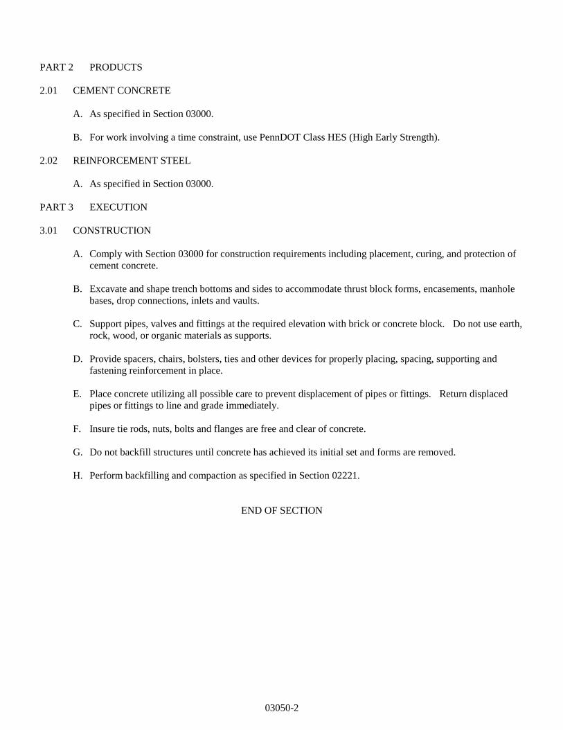
03050-2
PART 2 PRODUCTS
2.01 CEMENT CONCRETE
A. As specified in Section 03000.
B. For work involving a time constraint, use PennDOT Class HES (High Early Strength).
2.02 REINFORCEMENT STEEL
A. As specified in Section 03000.
PART 3 EXECUTION
3.01 CONSTRUCTION
A. Comply with Section 03000 for construction requirements including placement, curing, and protection of
cement concrete.
B. Excavate and shape trench bottoms and sides to accommodate thrust block forms, encasements, manhole
bases, drop connections, inlets and vaults.
C. Support pipes, valves and fittings at the required elevation with brick or concrete block. Do not use earth,
rock, wood, or organic materials as supports.
D. Provide spacers, chairs, bolsters, ties and other devices for properly placing, spacing, supporting and
fastening reinforcement in place.
E. Place concrete utilizing all possible care to prevent displacement of pipes or fittings. Return displaced
pipes or fittings to line and grade immediately.
F. Insure tie rods, nuts, bolts and flanges are free and clear of concrete.
G. Do not backfill structures until concrete has achieved its initial set and forms are removed.
H. Perform backfilling and compaction as specified in Section 02221.
END OF SECTION
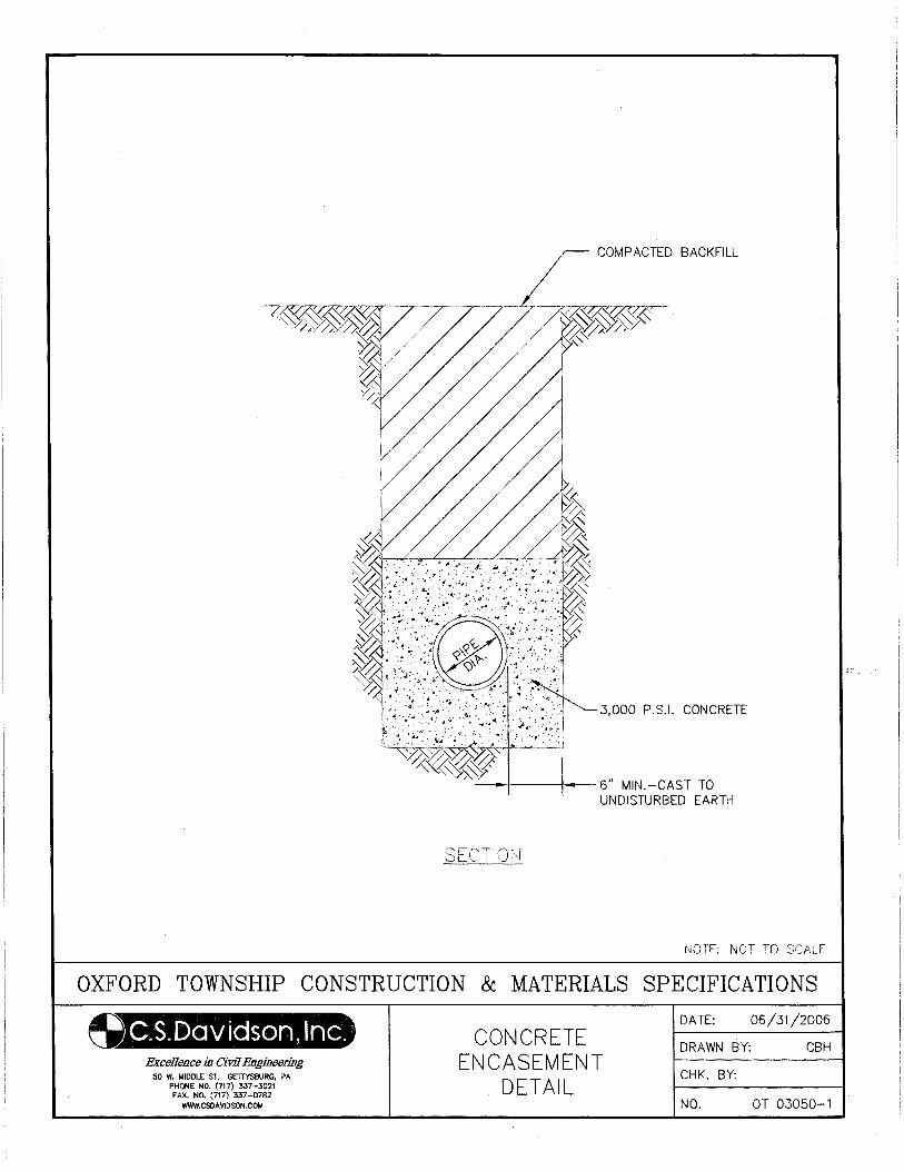
COMPACTED BACKFILL
NOTE: NOT TO SCALE
OXFORD TOWNSHIP CONSTRUCTION & MATERIALS SPECIFICATIONS
C.S. Dav iason, Inc. Excellence in Civil Engineering
50 W. MIDDLE ST. GETTYSBURG, PA PHONE NO. (717) 337-3021 FAX. NO. (717) 337-0782
WWW.CSOA VIDSON.COM
CONCRETE ENCASEMENT
DETAIL
DATE: 06/31/2006
DRAWN BY: CBH
CHK. BY:
NO. OT 03050-1
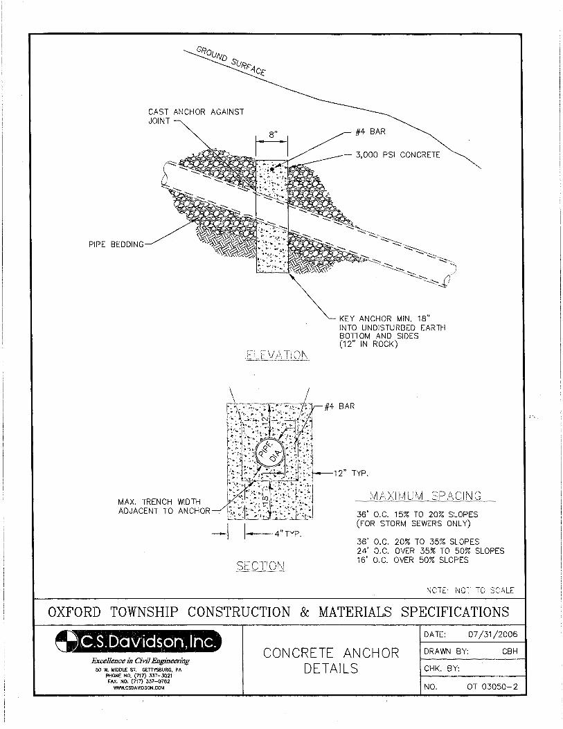
PIPE BEDDING
CAST ANCHOR AGAINST JOINT
MAX. TRENCH WIDTH ADJACENT TO ANCHOR
3,000 PSI CONCRETE
KEY ANCHOR MIN. 18" INTO UNDISTURBED EARTH BOTTOM AND SIDES (12" IN ROCK)
12" TYP.
-1 I---4"TYP.
36' O.C. 15% TO 20% SLOPES (FOR STORM SEWERS ONLY)
36' O.C. 20% TO 35% SLOPES 24' O.C. OVER 35% TO 50% SLOPES 16' O.C. OVER 50% SLOPES
OXFORD TOWNSHIP CONSTRUCTION & MATERIALS SPECIFICATIONS
O.S.DGJvictson, Inc. Excellence in Civil Engineering
50 W. MIDDLE ST. GETTYSBURG, PA PHONE NO. (717) 337-3021 FAX. NO. (717) 337-0782
WWW.CSDAVIDSON.COM
CONCRETE ANCHOR DETAILS
DATE: 07/31/2006
DRAWN BY: CBH
CHK. BY:
NO. OT 03050-2
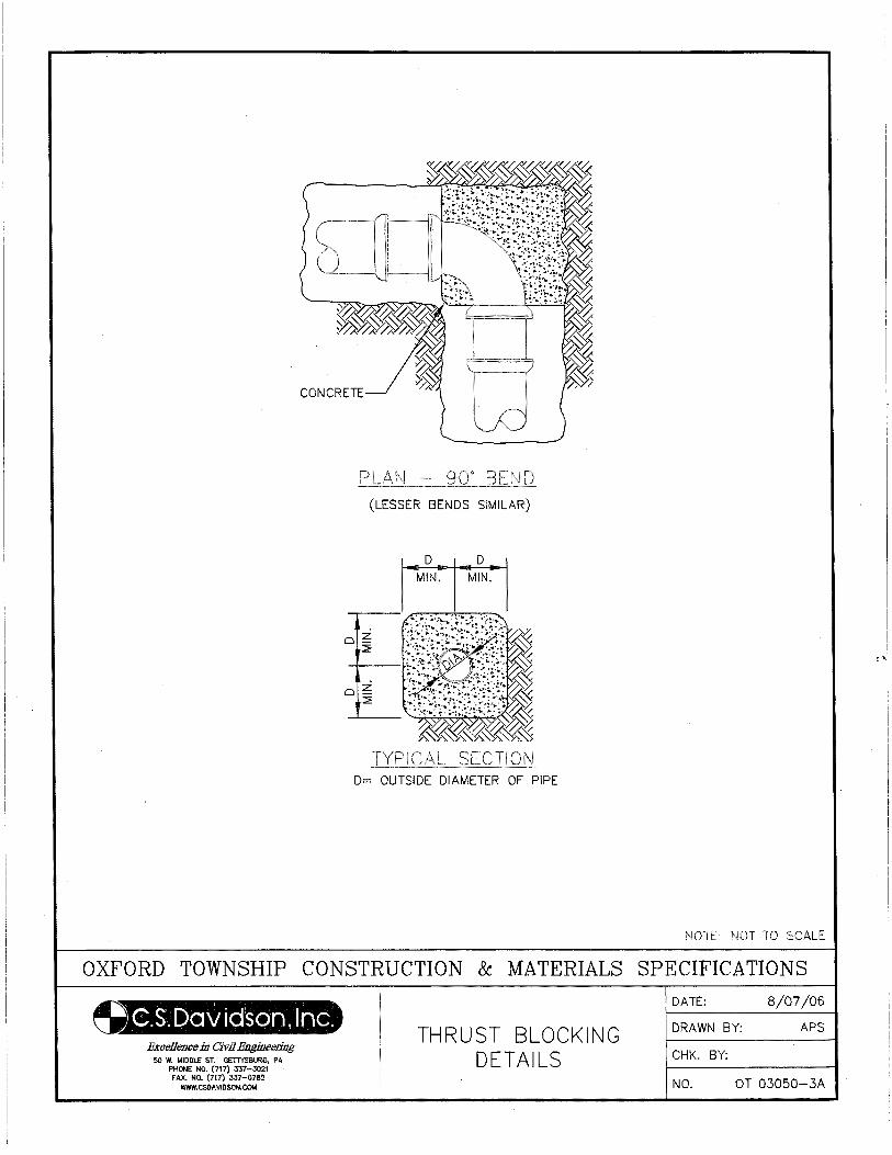
CONCRETE
(LESSER BENDS SIMILAR)
D= OUTSIDE DIAMETER OF PIPE
NOTE: NOT TO SCALE
OXFORD TOWNSHIP CONSTRUCTION & MATERIALS SPECIFICATIONS
C.S.Daviason, Inc. BxceUcncc in Civil Engineering
50 W. MIDDLE ST. GETT'l'SBURG, PA PHONE NO. (717) 337-3021 fAX. NO. (717) 337-0782
WWW.CSOAVIDSON.COM
THRUST BLOCKING DETAILS
DATE: 8/07/06
DRAWN BY: APS
CHK. BY:
NO. OT 03050-3A
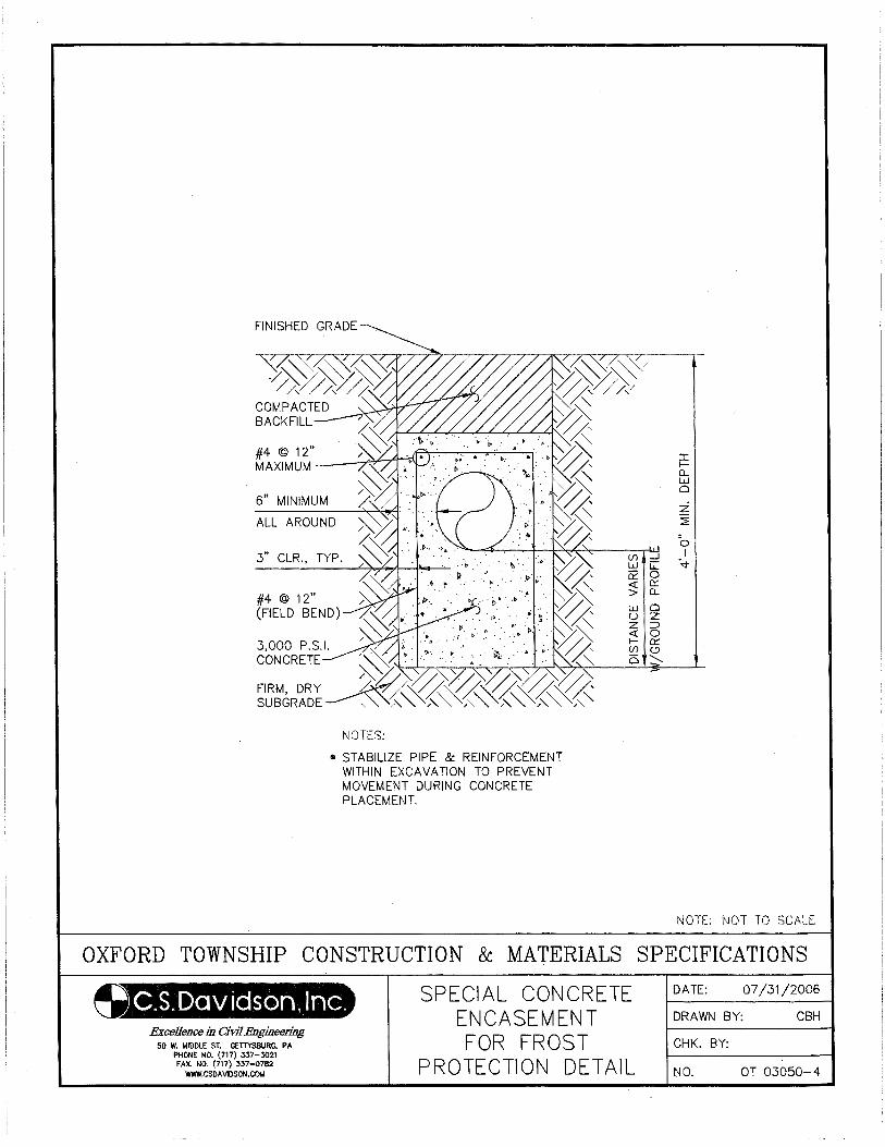
6" MINIMUM
ALL AROUND
I fa_ w 0
z ~
0 (f) ....J I w G: ~
#4 @ 12" (FIELD BEND)
NOTES:
• STABILIZE PIPE & REINFORCEMENT WITHIN EXCAVATION TO PREVENT MOVEMENT DURING CONCRETE PLACEMENT.
a:: 0 <( a::: > Q_
NOTE: NOT TO SCALE
OXFORD TOWNSHIP CONSTRUCTION & MATERIALS SPECIFICATIONS
~.S.Daviason, Inc. ExceUence in Civil Engineering
50 W. MIDDLE ST. GETTYSBURG, PA PHONE NO. (717) 337...:3021 FAX. NO. (717) 337-0782
WWW.CSDA VIDSON.COt.t
SPECIAL CONCRETE ENCASEMENT FOR FROST
PROTECTION DETAIL
DATE: 07/31 /2006
DRAWN BY: CBH
CHK. BY:
NO. OT 03050-4
16500-1
SECTION 16500
STREET LIGHTING
PART 1 - GENERAL
1.01 WORK INCLUDED
A. The Work of this Section includes, but is not limited to the installation of conduits, poles, controls, lighting
fixtures, lamps and wire necessary for a complete and functioning street lighting system.
B. Related work specified elsewhere:
1. Trenching, backfilling and compacting: Section 02221
2. Trench paving and restoration: Section 02575
3. Plain and reinforced cement concrete: Section 03000
4. Cement concrete for utility construction: Section 03050
C. Definitions: None
D. Applicable Standard Details:
OT 16500-1A Street Lighting Service Detail
OT 16500-2 Light Pole Detail
1.02 QUALITY ASSURANCE
A. Reference Standards:
ANSI American National Standard Institute
ASTM American Society for Testing and Materials
NEMA National Electrical Manufacturers Association
NECS National Electrical Safety Code
NFPA National Fire Protection Association
UL Underwriters’ Laboratories, Inc.
IESNA Illuminating Engineering Society of North America
IEEE Institute of Electrical & Electronics Engineers
IPCEA Insulated Power Cable Engineers Association
OSHA Occupational Safety & Health Administration
NEC National Electrical Code
B. Inspections:
1. Upon completion of work, customer/developer shall secure an electrical inspection from an electrical
inspection agency acceptable to the authority having jurisdiction and the local electric company.
C. Testing:
1. All electrical conductors, after installation of wiring and apparatus has been completed, shall be tested
by this Contractor to insure continuity, proper splicing, freedom from ground (except “made ground”
and those required for protection) and insulation resistance in accordance with Underwriters’
requirements. This Contractor shall furnish and employ suitable instruments such as ammeters, volt
meters, meggars, etc. Preliminary testing with magnetos will be permitted but will not be accepted as a
final or conclusive test.
16500-2
2. Prior to testing or adjusting, this Contractor shall consult with the Municipality to determine the
intended function of any equipment, wiring or systems. This Contractor shall then perform such tests
and make the necessary adjustments to ensure that the required function is obtained.
3. Equipment and wiring systems not specified as requiring a specific test shall be tested in operation to
determine that all design functions are satisfactorily performed.
1.03 SUBMITTALS
A. Submit (in triplicate ) Certificate of Compliance following electrical inspection.
B. Voltage drop calculations, prepared by a Professional Engineer licensed in Pennsylvania.
C. Photometric data for lighting fixtures and point by point maintained footcandle print out that includes
maximum maintained footcandles, minimum maintained footcandles, average maintained footcandles,
maximum : minimum ratio, average : minimum ratio.
D. Efficiency and candle power distribution curve for each type lighting fixture.
E. Catalog cuts and dimensional data for poles and lighting fixtures proposed.
F. Concrete base design.
1.04 JOB CONDITIONS
A. Codes and Standards:
1. All electrical work shall meet the requirements of National Electric Code of the National Fire Protection
Association. In addition, any state, municipal or other authorities laws, rules or regulations applicable to
the work shall be followed.
2. Where applicable, all materials and equipment shall bear the label of approval of the Underwriters
Laboratory, Inc.
3. Photometric performance of the installed lighting system shall be within guidelines established by The
Illuminating Society of North America.
4. Reference to the codes and standards listed herein shall constitute the minimum acceptable
requirements. Where drawings and specification requirements exceed those of the codes listed herein,
Contractor shall follow the drawings and specifications.
1.05 COORDINATION - DEVELOPMENT STREET LIGHTING
A. The electric company's street lighting service is only available to the Municipality. The developer shall
coordinate street lighting requests with the Township and all street lighting shall conform to the
Municipality's and electric company's street lighting specifications.
B. Customer/developer shall provide the electric company with a preliminary plan showing proposed locations
of street light standards. The electric company does not design or approve design of street lighting
systems.
C. The electric company returns plan showing the available source(s) for the street light feed(s) and, if not
previously provided, this document which lists material requirements.
D. Customer/developer shall provide street light luminaire(s) which is equipped to operate with the material, as
specified herein and as approved the electric company.
16500-3
E. Requirements:
1. Street lights shall be spaced at regular intervals as necessary to conform to the performance criteria.
Minor adjustments to spacing may be made to accommodate lot lines, driveways, etc.
2. Customer/developer shall provide the electric company with a final plan showing location of facilities
(street lights, service equipment, conduit and cable routing, etc.) and size and type of cables and fusing.
3. Prior to excavating, the contractor shall call the PA One Call system.
4. Customer/developer shall install facilities in accordance with requirements of the electric company, the
Municipality, the manufacturer, the National Electric Code, and final plan. The customer/developer is
require to provide and/or install:
a. All trenching and backfilling, including service cable from source to junction box.
b. All cable, conduit, foundations, standards, luminaires, lamps, and photoelectric controls as per
developer agreement with municipality.
c. Service equipment at each source location designated by the electric company to facilitate street
lighting cable connections.
5. Customer/developer shall secure an electrical inspection from the electric company accepted electrical
inspection agency before the electric company will energize.
6. Upon receipt of a street lighting agreement from the municipality and the electrical inspection
certificate, the electric company will:
a. Install service to the line side of the service equipment.
b. Install on each streetlight standard and identification tag to show grid location and an additional tag
to show the maintenance agreement, lamp type and size.
7. Note that a contract for energy and maintenance of fixtures with the Municipality and the electric
company is required prior to the electric company energizing the street lighting system.
1.06 CALCULATIONS
A. Voltage drop shall be calculated to ensure voltage drop will not exceed the requirements of the National
Electrical Code.
B. Point by point footcandle calculations shall be performed to verify that lighting system photometric
performance conforms to the IESNA recommendations, as adopted by the Municipality.
PART 2 - PRODUCTS
2.01 FIXTURE
A. See Specification Drawing OT-16500-2
B. Substitution from Section 2.01A will be considered by Township only if unique situations apply. Approvals
of substitutions will be at the discretion of the Board of Supervisors.
2.03 POLES
A. See Specification Drawing OT-16500-2
16500-4
B. Substitution from Section 2.01.A will be considered by Township only if unique situations apply. Approvals
of substitutions will be at the discretion of the Board of Supervisors.
2.04 FUSE AND FUSE HOLDER
A. Fuse and fuse holder for the fuse disconnect in the customer’s junction box shall be per the electric
company's requirements, fuse size as required.
2.05 STRUCTURAL REQUIREMENTS
A. All poles, concrete bases, fixtures shall be installed as an integral unit to withstand 100 mph winds, 120
mph gusts.
B. All pole embedded depths and/or concrete bases shall be shown on the drawings, shall be designed by and
the design drawings sealed by a Professional Engineer, licensed in Pennsylvania, taking into account soil
conditions at the location of the pole.
C. All dimensions of the pole, base plate, material type and thickness, and welding information shall appear
on the shop drawings along with wind loading for pole and lighting fixtures.
2.06 CONDUIT
A. Polyvinyl Chloride (PVC) - Schedule 40.
B. Extruded from virgin polyvinyl chloride compound.
C. Resistant to water, oil, outdoor aging, exposure to sunlight, underground environments, and corrosive
atmospheres.
D. Flame retardant for use above ground, resistant to low temperatures, and resistant to distortion due to heat
under conditions likely to be encountered in intended service.
E. Sufficient strength to withstand abuse, such as impact and crushing during handling, installation, and
service. Ten foot lengths with one coupling furnished for each length.
F. Minimum Size: 1 inch.
G. Each length clearly and durably marked with manufacturer’s name. Markings shall be permanent for PVC
used above ground.
H. PVC conduit shall be UL listed.
I. Comply with applicable ASTM testing procedures and specifications.
J. Fittings:
1. Conform to applicable PVC conduit specifications above.
2. Manufacturer: Same as PVC conduit manufactures.
2.07 WIRE
A. All wire and cable shall conform to the following:
1. Copper shall not be less than 98 percent conductivity.
2. Single conductor, unless otherwise indicated.
3. Color coded.
4. Marked with classification type, conductor size, and voltage rating, every foot, where applicable.
16500-5
5. Minimum Size: #12 AWG, unless otherwise specified.
6. Sizes #8 AWG and larger shall be stranded.
7. UL listed.
B. Wire Specification No. 1
1. Type THW insulation, UL listed.
2. 600 volt insulation.
3. Ampacity based upon maximum conductor temperature of 75 degrees C. in wet or dry locations,
continuous operation.
4. Conform to ASTM B3 for solid conductors and ASTM B8 for stranded conductor.
5. Annealed, uncoated copper conductor.
6. Flame retardant, moisture and heat resistant thermoplastic (PVC) insulation.
C. Wire Specification No. 2
1. Type XHHW insulation, UL listed.
2. 600 volt insulation.
3. Ampacity based upon maximum conductor temperature of 90 degrees C. dry locations and 75 degrees C.
wet locations, continuous operation.
4. Moisture and heat resistant cross linked polyethylene (XLP) insulation.
5. Conform to applicable NEMA and IPCEA requirements.
6. Conform to ASTM B3 for solid conductors and ASTM B8 for stranded conductors.
7. Soft copper conductor.
D. Wire Specification No. 4
1. Type THHN/THWN insulation, UL listed.
2. 600 volt insulation.
3. Ampacity based upon maximum conductor temperature of 90 degrees C. dry locations (THHNO and 75
degrees C. dry and wet locations (THWN)), continuous operation.
4. Flame retardant, moisture and heat resistant thermoplastic (PVC) insulation with nylon jacket.
5. Conform to applicable NEMA and IPCEA requirements.
6. Conform to ASTM B3 for solid conductors and ASTM B8 for stranded conductors.
7. Soft copper conductor.
2.08 CONNECTORS
A. Connector Specification No. 1 - Splice Connectors
1. For insulated wire, 600 volt and under, #8 AWG and smaller.
2. Compression solderless connector.
3. Insulated or non-insulated.
4. UL listed.
5. Manufacturer: Buchanan B-cap.
6. Substitutions: Ideal Wing-nut, 3M Schotchlok.
B. Connector Specification No. 2 - Splice Connectors
1. For insulated wire, 600 volts and under, #6 AWG and larger.
2. Split bolt pressure connector.
3. Bronze.
4. UL listed.
5. Manufacturer: Anderson.
6. Substitutions: Thomas & Betts, Penn-Union, Dossert, Burndy, Reliable Electric, Ideal.
16500-6
C. Connector Specification No. 3 - Splice Connectors
1. For insulated wire, 600 volts and under, #6 AWG and larger.
2. Compression or crimp connector, short sleeve.
3. Copper.
4. UL listed.
5. Manufacturer: Anderson.
6. Substitutions: Thomas & Betts, Dossert, Burndy, MAC, 3M, Ideal.
D. Connector Specification No. 4 - Lug connector
1. For insulated wire, 600 volt and under, #8 AWG and larger.
2. Compression or crimp connector, short sleeve.
3. Copper.
4. UL listed.
5. Manufacturer: Anderson.
6. Substitutions: Thomas & Betts, Penn-Union, Dossert, Burndy, MAC, 3M, Ideal.
E. Connector Specification No. 5 - Lug connector
1. For insulated wire, 600 volt and under, #8 AWG and larger.
2. Bolted type pressure connection, hex head or hex socket pressure bolts.
3. Copper.
4. UL listed.
5. Manufacturer: Penn-Union.
6. Substitutions: Thomas & Betts, Anderson, Dossert, Burndy, Ideal.
F. Connector Specification No. 6 - Lug Connector.
1. For insulated wire, 600 volt and under, #10 AWG and smaller.
2. Compression or crimp type.
3. Standard barrel, insulated for 600 volts.
4. Ring terminal or flanged or flared block spade terminal.
5. Copper.
6. UL listed.
7. Manufacturer: Penn-Union Penn Crimp.
8. Substitutions: Ideal Crimp Terminal, Thomas & Betts Sta-Kon, Burndy Insulug, MAC MiniDent, 3M
Scotchlok Terminals.
G. Connector Application
1. Unless otherwise noted, connectors shall be used for insulated wire, 600 volts and under as follows:
16500-7
CONNECTOR SCHEDULE
Application Connector Spec. No.
Splice Connectors:
#8 AWG and smaller 1
#6 AWG and larger 2 or 3
Lug Connectors:
Stranded wire connection under head of
binding screw or bolt
4 or 6
Connection to equipment bus, or screw
or bolt terminals
4, 5, 6, or manufacturer supplied lugs
2.9 TAPE
A. Tape Specification No. 1 - Tape for Insulation 600 Volts or Less
1. Vinyl plastic all weather electrical tape.
2. Manufacturer: 3M Scotch 33+.
3. Substitutions: Tomic, Okonite.
B. Tape Specification No. 2 - Underground Marker Tape
1. Material: Red, plastic, 6 inches wide.
2. Marking: CAUTION - BURIED ELECTRIC LINE BELOW, or similar wording.
3. Manufacturer: Griffolyn, Inc.
4. Substitutions: Allen Company.
2.10 WIRE MARKERS
A. Wire Marker Specification No. 2 - Vinyl plastic or Vinyl Polyester.
1. Temperature Range: to 250 degrees F.
2. Self-sticking adhesive backing.
3. Waterproof, solvent proof.
4. Printing permanently protected.
5. Manufacturer: Thomas & Betts E-Z-Code, Type WSL.
6. Substitutions: W.H. Brady Co. Type CAB.
2.11 GROUND RODS
A. Type: High strength steel core.
B. Construction : Copper exterior welded to the steel core.
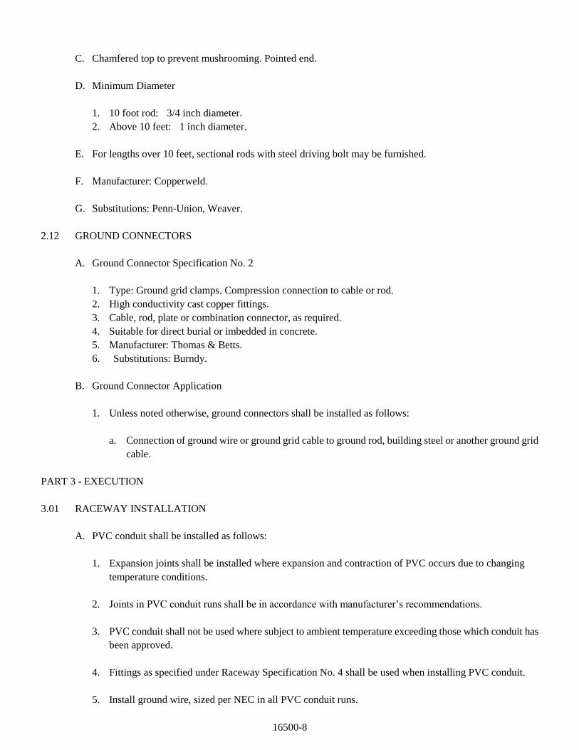
16500-8
C. Chamfered top to prevent mushrooming. Pointed end.
D. Minimum Diameter
1. 10 foot rod: 3/4 inch diameter.
2. Above 10 feet: 1 inch diameter.
E. For lengths over 10 feet, sectional rods with steel driving bolt may be furnished.
F. Manufacturer: Copperweld.
G. Substitutions: Penn-Union, Weaver.
2.12 GROUND CONNECTORS
A. Ground Connector Specification No. 2
1. Type: Ground grid clamps. Compression connection to cable or rod.
2. High conductivity cast copper fittings.
3. Cable, rod, plate or combination connector, as required.
4. Suitable for direct burial or imbedded in concrete.
5. Manufacturer: Thomas & Betts.
6. Substitutions: Burndy.
B. Ground Connector Application
1. Unless noted otherwise, ground connectors shall be installed as follows:
a. Connection of ground wire or ground grid cable to ground rod, building steel or another ground grid
cable.
PART 3 - EXECUTION
3.01 RACEWAY INSTALLATION
A. PVC conduit shall be installed as follows:
1. Expansion joints shall be installed where expansion and contraction of PVC occurs due to changing
temperature conditions.
2. Joints in PVC conduit runs shall be in accordance with manufacturer’s recommendations.
3. PVC conduit shall not be used where subject to ambient temperature exceeding those which conduit has
been approved.
4. Fittings as specified under Raceway Specification No. 4 shall be used when installing PVC conduit.
5. Install ground wire, sized per NEC in all PVC conduit runs.
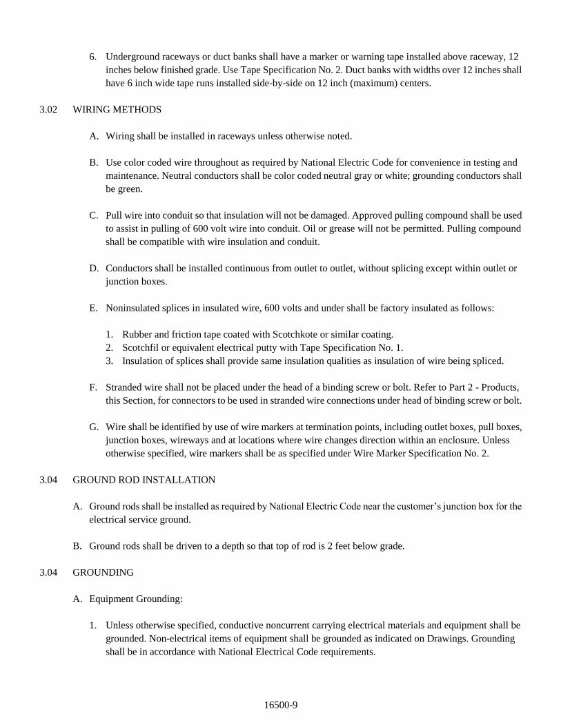
16500-9
6. Underground raceways or duct banks shall have a marker or warning tape installed above raceway, 12
inches below finished grade. Use Tape Specification No. 2. Duct banks with widths over 12 inches shall
have 6 inch wide tape runs installed side-by-side on 12 inch (maximum) centers.
3.02 WIRING METHODS
A. Wiring shall be installed in raceways unless otherwise noted.
B. Use color coded wire throughout as required by National Electric Code for convenience in testing and
maintenance. Neutral conductors shall be color coded neutral gray or white; grounding conductors shall
be green.
C. Pull wire into conduit so that insulation will not be damaged. Approved pulling compound shall be used
to assist in pulling of 600 volt wire into conduit. Oil or grease will not be permitted. Pulling compound
shall be compatible with wire insulation and conduit.
D. Conductors shall be installed continuous from outlet to outlet, without splicing except within outlet or
junction boxes.
E. Noninsulated splices in insulated wire, 600 volts and under shall be factory insulated as follows:
1. Rubber and friction tape coated with Scotchkote or similar coating.
2. Scotchfil or equivalent electrical putty with Tape Specification No. 1.
3. Insulation of splices shall provide same insulation qualities as insulation of wire being spliced.
F. Stranded wire shall not be placed under the head of a binding screw or bolt. Refer to Part 2 - Products,
this Section, for connectors to be used in stranded wire connections under head of binding screw or bolt.
G. Wire shall be identified by use of wire markers at termination points, including outlet boxes, pull boxes,
junction boxes, wireways and at locations where wire changes direction within an enclosure. Unless
otherwise specified, wire markers shall be as specified under Wire Marker Specification No. 2.
3.04 GROUND ROD INSTALLATION
A. Ground rods shall be installed as required by National Electric Code near the customer’s junction box for the
electrical service ground.
B. Ground rods shall be driven to a depth so that top of rod is 2 feet below grade.
3.04 GROUNDING
A. Equipment Grounding:
1. Unless otherwise specified, conductive noncurrent carrying electrical materials and equipment shall be
grounded. Non-electrical items of equipment shall be grounded as indicated on Drawings. Grounding
shall be in accordance with National Electrical Code requirements.
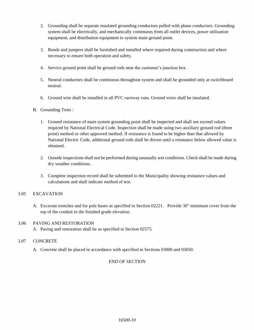
16500-10
2. Grounding shall be separate insulated grounding conductors pulled with phase conductors. Grounding
system shall be electrically, and mechanically continuous from all outlet devices, power utilization
equipment, and distribution equipment to system main ground point.
3. Bonds and jumpers shall be furnished and installed where required during construction and where
necessary to ensure both operation and safety.
4. Service ground point shall be ground rods near the customer’s junction box.
5. Neutral conductors shall be continuous throughout system and shall be grounded only at switchboard
neutral.
6. Ground wire shall be installed in all PVC raceway runs. Ground wires shall be insulated.
B. Grounding Tests :
1. Ground resistance of main system grounding point shall be inspected and shall not exceed values
required by National Electrical Code. Inspection shall be made using two auxiliary ground rod (three
point) method or other approved method. If resistance is found to be higher than that allowed by
National Electric Code, additional ground rods shall be driven until a resistance below allowed value is
obtained.
2. Outside inspections shall not be performed during unusually wet conditions. Check shall be made during
dry weather conditions.
3. Complete inspection record shall be submitted to the Municipality showing resistance values and
calculations and shall indicate method of test.
3.05 EXCAVATION
A. Excavate trenches and for pole bases as specified in Section 02221. Provide 30" minimum cover from the
top of the conduit to the finished grade elevation.
3.06 PAVING AND RESTORATION
A. Paving and restoration shall be as specified in Section 02575.
3.07 CONCRETE
A. Concrete shall be placed in accordance with specified in Sections 03000 and 03050.
END OF SECTION
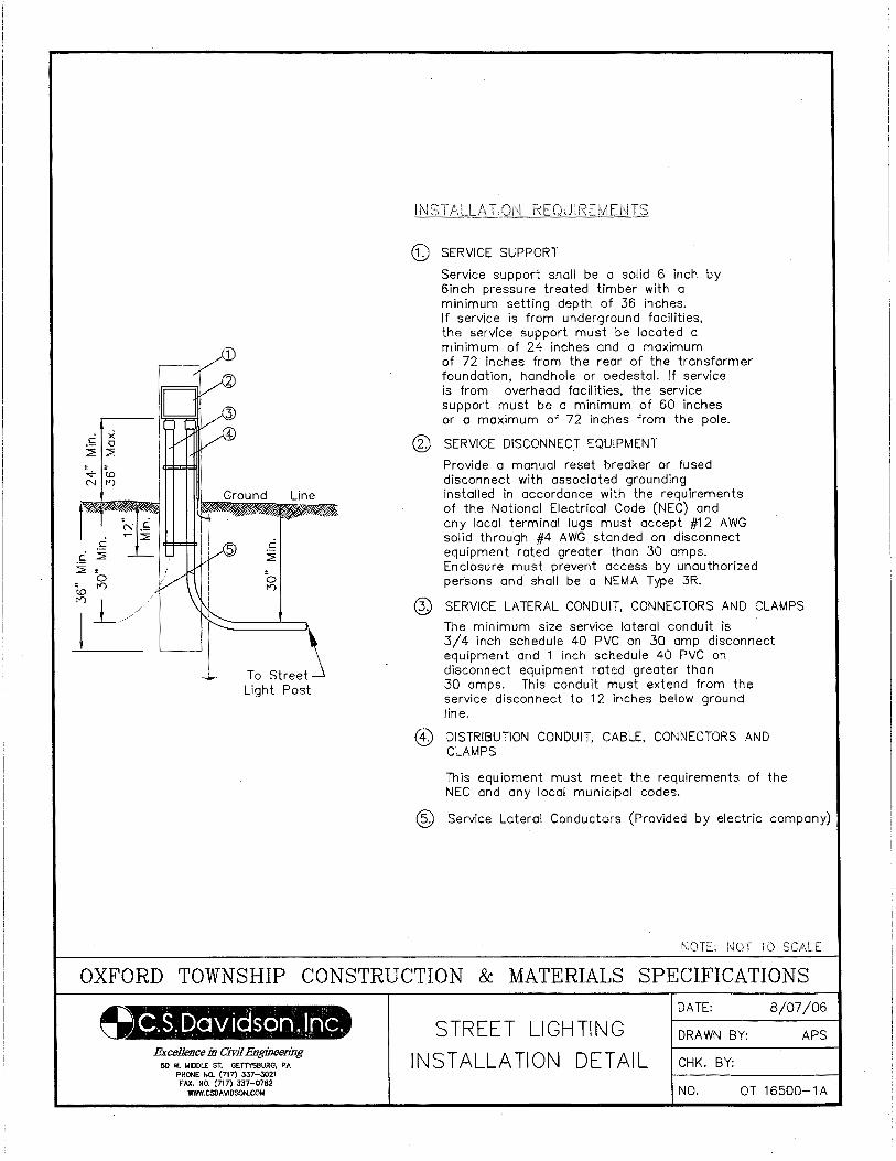
Line
To Street Light Post
([) SERVICE SUPPORT
Service support shall be a solid 6 inch by 6inch pressure treated timber with a minimum setting depth of 36 inches. If service is from underground facilities, the service support must be located a minimum of 24 inches and a maximum of 72 inches from the rear of the transformer foundation, hondhole or pedestal. If service is from overhead facilities, the service support must be a minimum of 60 inches or a maximum of 72 inches from the pole.
@ SERVICE DISCONNECT EQUIPMENT
Provide a manual reset breaker or fused disconnect with associated grounding installed in accordance with the requirements of the Notional Electrical Code (NEC) and any local terminal lugs must accept #12 AWG solid through #4 AWG stonded on disconnect equipment rated greater than 30 amps. Enclosure must prevent access by unauthorized persons and shall be a NEMA Type 3R.
SERVICE LATERAL CONDUIT, CONNECTORS AND CLAMPS
The minimum size service lateral conduit is 3/4 inch schedule 40 PVC on 30 amp disconnect equipment and 1 inch schedule 40 PVC on disconnect equipment rated greater than 30 amps. This conduit must extend from the service disconnect to 12 inches below ground line.
DISTRIBUTION CONDUIT, CABLE. CONNECTORS AND CLAMPS
This equipment must meet the requirements of the NEC and any local municipal codes.
@ Service Lateral Conductors (Provided by electric company)
NOTE: NOT TO
OXFORD TOWNSHIP CONSTRUCTION & MATERIALS SPECIFICATIONS
~.S.Dav ieison, Inc. Excellence in Civil Engineering
50 W. MIDDLE ST. GETTYSBURG, PA PHONE NO. (717} 337-3021 FAX. NO. (717) 337-0782
WWW.CSDAIIIOSON.COM
STREET LIGHTING INSTALLATION DETAIL
DATE: 8/07/06
ORA WN BY: APS
CHK. BY:
NO. OT 16500-1A
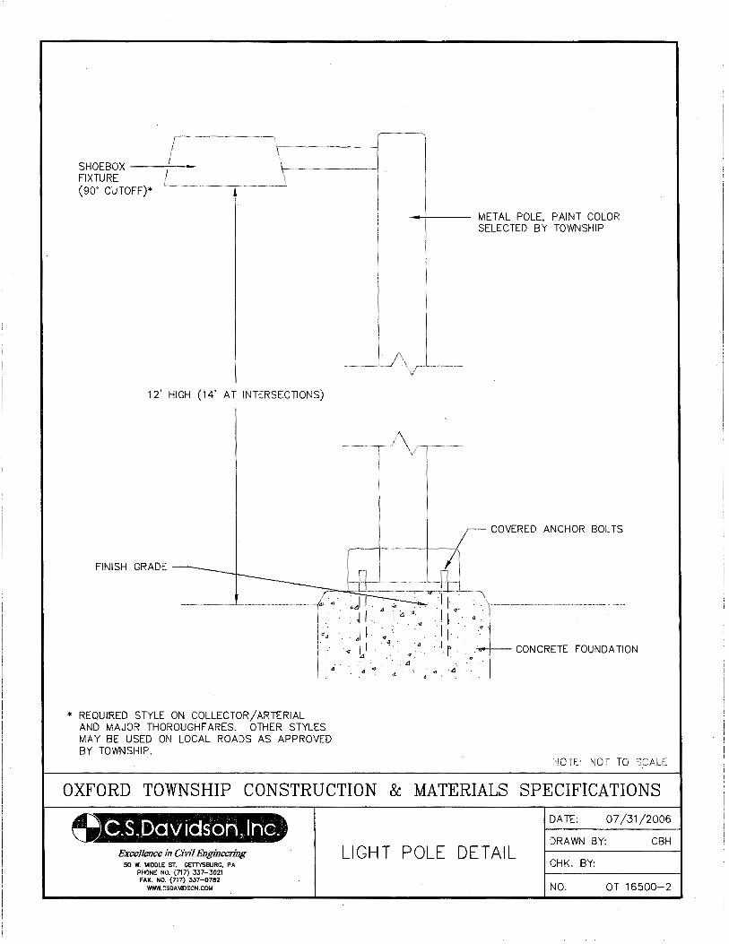
SHOEBOX --+-FIXTURE (90' CUTOFF)*
12' HIGH (14' AT INTERSECTIONS)
FINISH GRADE -..__
* REQUIRED STYLE ON COLLECTOR/ARTERIAL AND MAJOR THOROUGHFARES. OTHER STYLES MAY BE USED ON LOCAL ROADS AS APPROVED BY TOWNSHIP.
--!--- METAL POLE, PAINT COLOR SELECTED BY TOWNSHIP
COVERED ANCHOR BOLTS
-+- CONCRETE FOUNDATION
NOTE: NOT TO SCALE
OXFORD TOWNSHIP CONSTRUCTION & MATERIALS SPECIFICATIONS
~.S.IJDCH.lidSOJ"l, lnG. ExccUence in CiVJ7 Engineering
50 W. MIDDLE ST. GETTYSBURG, PA PHONE NO. (717) 337-3021 FAX. NO. (717} 337-0782
WWW.CSDAVIDSON.COM
LIGHT POLE DETAIL
DATE: 07/31/2006
DRAWN BY: CBH
CHK. BY:
NO. OT 16500-2