Embed Size (px)
Citation preview
Oxford™ Partial Knee Manual of the Surgical Technique

3
The Surgical Technique herein is presented to demonstrate the technique developed and utilised by Prof. D.W. Murray, Mr. J. Goodfellow, Prof. J. O’Connor and Mr. C. Dodd, of the Nuffield Orthopaedic Centre, Oxford, U.K. Biomet UK Ltd., as the manufacturer of this device, does not practice medicine and therefore, does not recommend this technique or produce for any individual patient.
Disclaimer
4
Oxford™ Partial Knee Manual of the Surgical Technique
contentsThe Oxford Partial Knee 2
Femoral Components 2
Tibial Components 3
Meniscal Bearings 3
Choice of Patient 4
The Place for Partial Knee Replacement 6
The Learning Curve 6
Preoperative Planning 7
The Operation 10
Positioning the Limb 10
Incision 10
Excision of Osteophytes 11
Tibial Plateau Resection 12
The Femoral Drill Holes 16
Femoral Saw Cut 19
First Milling of the Condyle 20
Equalising the 90˚ and 20˚ Flexion Gaps 22
Confirming Equality of the 90˚ and 20˚ Flexion and Extension Gaps 23
Preventing Impingement 24
Final Preparation of the Tibial Plateau 25
Trial Reduction 27
Cementing the Components 28
Key to Instruments 30
References 33
Appendix 34
Postoperative Treatment 34
Postoperative Radiographic Assessment 34
Radiographic Criteria 35
Follow up Radiographs 37
Product Listing 38
2
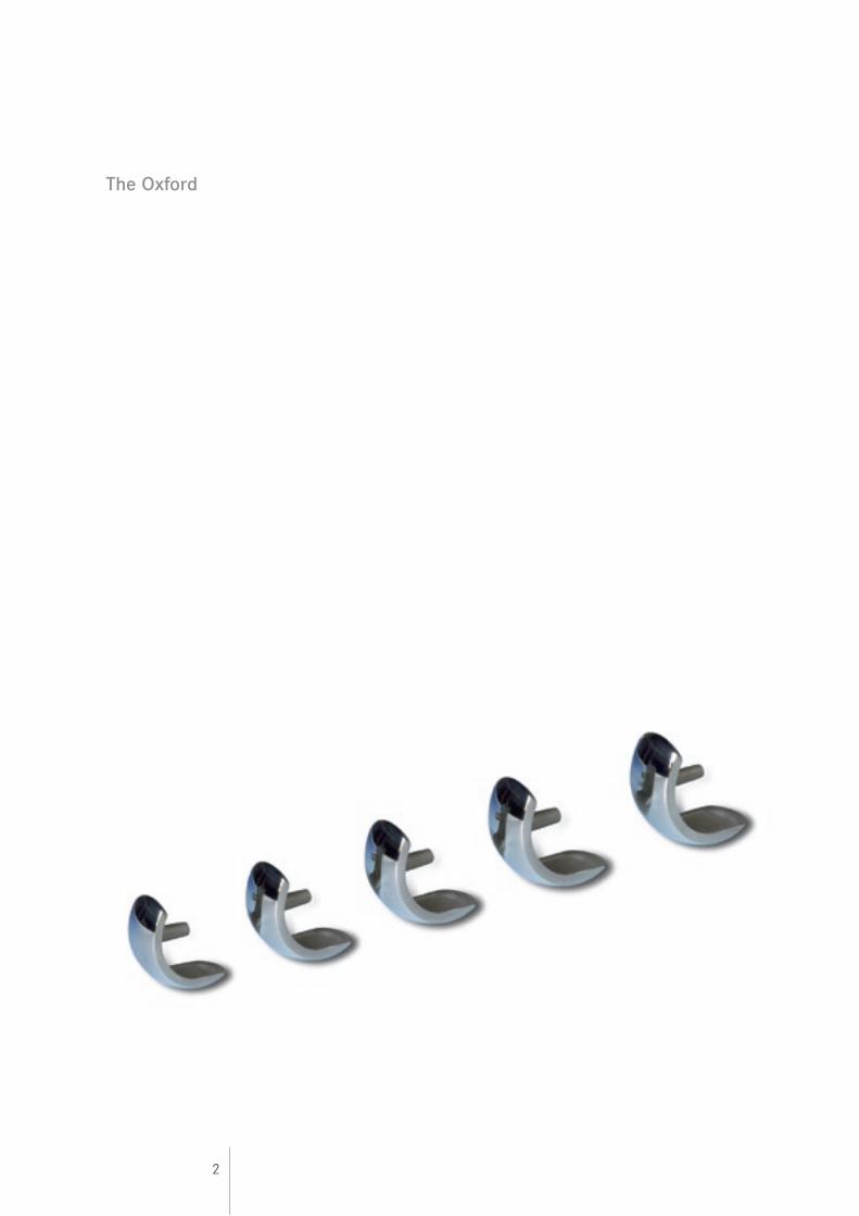
The Oxford
3
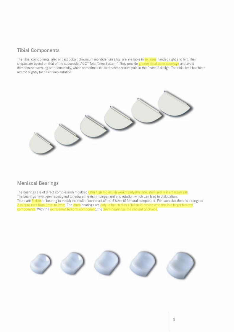
Tibial Components
The tibial components, also of cast cobalt chromium molybdenum alloy, are available in six sizes handed right and left. Their shapes are based on that of the successful AGC™ Total Knee System7. They provide greater tibial bone coverage and avoid component overhang anteriomedially, which sometimes caused postoperative pain in the Phase 2 design. The tibial keel has been altered slightly for easier implantation.
Meniscal Bearings
The bearings are of direct compression moulded ultra high molecular weight polyethylene, sterilised in inert argon gas. The bearings have been redesigned to reduce the risk impingement and rotation which can lead to dislocation.There are 5 sizes of bearing to match the radii of curvature of the 5 sizes of femoral component. For each size there is a range of 7 thicknesses from 3mm to 9mm. The 3mm bearings are only to be used as a ‘fail safe’ device with the four larger femoral components. With the extra-small femoral component, the 3mm bearing is the implant of choice.
4
Choice of Patient
There are well defined circumstances in which the Oxford medial arthroplasty is appropriate and certain criteria must be fulfilled for success. In principle, the soft tissue components of the joint and the articular surfaces of the lateral compartment must all be intact. The operation is most suitable for the treatment of anteromedial osteoarthritis4.
Both cruciate ligaments must be intact. The posterior cruciate is seldom diseased in osteoarthritic knees but the anterior cruciate is often damaged and is sometimes absent. Since the implant is completely unrestrained in the anteroposterior plane, the stability of the prosthesis depends on an intact cruciate mechanism. Stability cannot be restored if the anterior cruciate ligament is badly damaged or absent and this deficiency is a contraindication to the procedure.
It is however appropriate to proceed if the ligament is superficially damaged, denuded of synovium or split. Posterior tibial bone loss (on the lateral radiograph), strongly suggests damage to the cruciate mechanism and, therefore, that the joint is inappropriate8 for this proceedure. The lateral compartment should be well preserved, with an intact meniscus and full thickness of articular cartilage. This is best demonstrated by the presence of a full thickness ‘joint space’ visible on an AP radiograph taken with the joint 20˚ flexed and stressed into valgus9. Superficial fibrillation, marginal osteophytes and even localised areas of erosion of the cartilage on the medial margin of the lateral condyle are frequently seen at surgery and are not contraindications to medial compartment arthroplasty. Malalignment of the limb.The intraarticular deformity caused by the bone and cartilage loss must be passively correctable to neutral and not beyond. A good way to confirm this is to take stressed radiographs9.
The degree of deformity is not so important as its ability to be passively corrected by the application of a valgus force. Varus deformity of more than 15˚ can seldom be passively corrected to neutral and, therefore, this figure represents the outer limit. Soft tissue release should never be performed. If the medial collateral ligament has shortened and passive correction of the varus is impossible, the arthritic process has progressed beyond the stage suitable for this procedure.
Flexion deformity should be less than 15˚. Partial arthroplasty has only a limited ability to improve flexion deformity. If the preoperative deformity is excessive, it should not be employed.
The knee must be able to flex to at least 110˚ under anaesthetic to allow access for preparation of the femoral condyle.
Patellofemoral arthritis is not a contraindication. Extensive fibrillation and full thickness erosions are commonly seen on the medial patellar facet and the medial flange of the patellar groove of the femur, but realignment of the limb by Partial Knee replacement unloads these damaged areas of the patellofemoral joint. No correlation has been found between the success of the operation and the state of the patellofemoral joint. In more than 500 cases reported by Murray et al5 and Price et al6, no knee was revised because of patellofemoral problems.
Several other contraindications to Partial Knee replacement which have been proposed have been found unnecessary. Neither the patient’s age10, weight3 nor activity level11 are contraindications nor the presence of chondrocalcinosis12.
Partial Knee arthroplasty is contraindicated in all forms of inflammatory arthritis. (The pathological changes of early rheumatoid arthritis can be confused with those of medial compartment osteoarthritis.)
The high success rates reported5,6 were achieved in patients with anteromedial osteoarthritis and they may not be achieved with other diagnoses. The Oxford implant has also been used successfully in the treatment of primary avascular necrosis, and in a few patients, combined with replacement of an absent anterior cruciate for secondary osteoarthritis14,15.
5
The Oxford Knee is not designed for use in the lateral compartment. The ligaments of the lateral compartment are more elastic than those of the medial and a 10% rate of early dislocation of the bearing is reported. Access through a small incision is more difficult laterally than medially. A considered opinion on the subject of lateral compartment arthroplasty using the Oxford Knee Phase 2 is given in the paper by Gunther et al is recommended that the fixed bearing, (Vanguard M), Partial Knee replacement is used instead16. The final decision, whether or not to perform Partial Knee arthroplasty, is made when the knee has been opened and directly inspected.
6
The Place for Partial Knee Replacement
In cases of osteoarthritis, Partial knee replacement competes with upper tibial osteotomy at one end of the disease spectrum and with total condylar joint replacement at the other.
It has the advantages over tibial osteotomy of providing more certain relief of pain, quicker recovery, and better long term survival.In appropriate cases.
It has the advantage over total replacement of providing more physiological function, better range of movement and quicker recovery. Nevertheless, patients who require knee replacement and who do not fulfil the above criteria are better treated by total knee arthroplasty.
Using the criteria given above, about one in four osteoarthritic knees requiring replacement are suitable for Oxford medial Partial arthroplasty.
The Learning Curve
This Operative Manual should be used in association with the Instructional Video/DVD of the operation (available from Biomet UK Ltd). As with other surgical procedures, errors of technique are more likely when the method is being learned. To reduce these to a minimum, surgeons are strongly recommended to attend an Instructional Course on the Oxford Knee before attempting the operation.
7
Preoperative planning
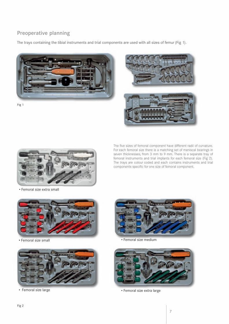
The trays containing the tibial instruments and trial components are used with all sizes of femur (Fig 1).
Fig 1
Fig 2
• Femoral size small • Femoral size medium
• Femoral size large • Femoral size extra large
The five sizes of femoral component have different radii of curvature. For each femoral size there is a matching set of meniscal bearings in seven thicknesses, from 3 mm to 9 mm. There is a separate tray of femoral instruments and trial implants for each femoral size (Fig 2). The trays are colour coded and each contains instruments and trial components specific for one size of femoral component.
• Femoral size extra small
8
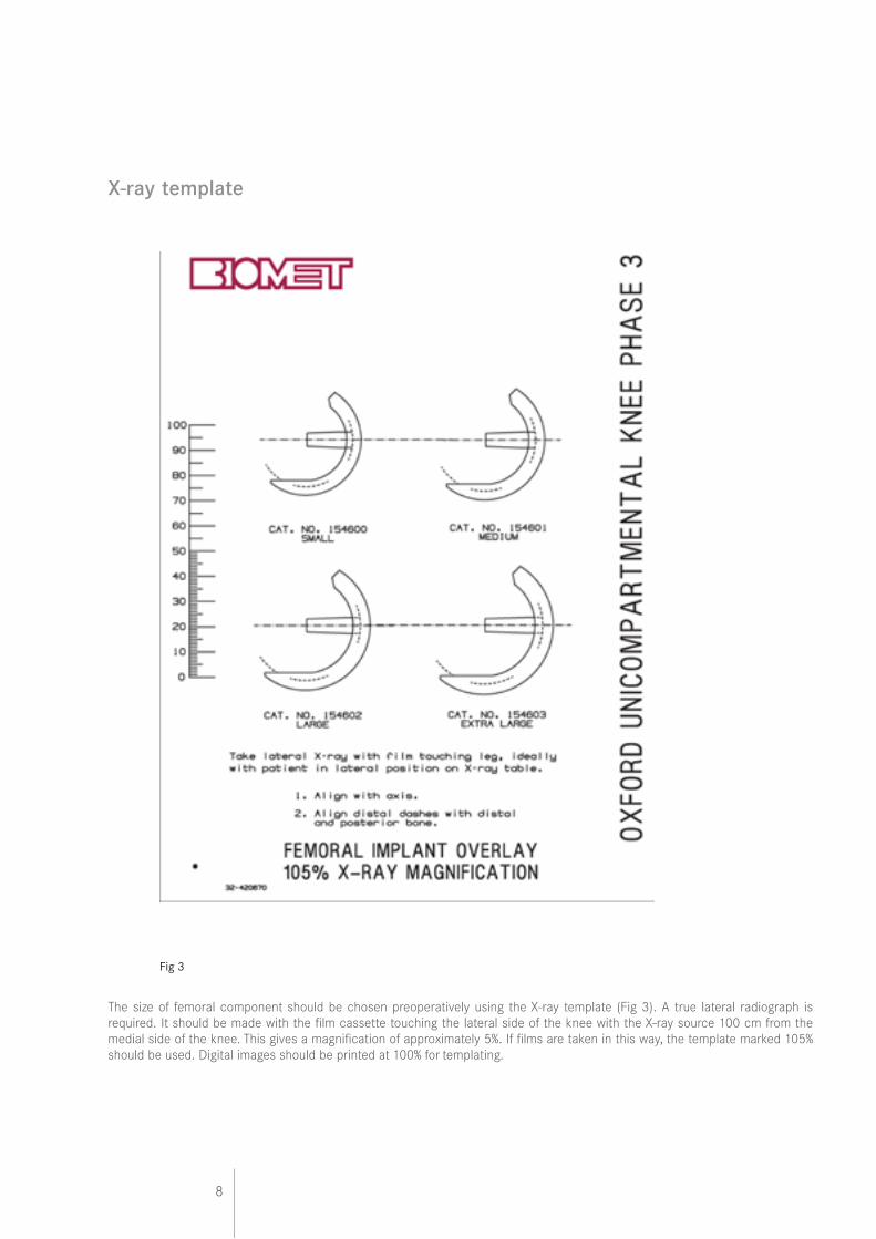
X-ray template
The size of femoral component should be chosen preoperatively using the X-ray template (Fig 3). A true lateral radiograph is required. It should be made with the film cassette touching the lateral side of the knee with the X-ray source 100 cm from the medial side of the knee. This gives a magnification of approximately 5%. If films are taken in this way, the template marked 105% should be used. Digital images should be printed at 100% for templating.
Fig 3
9
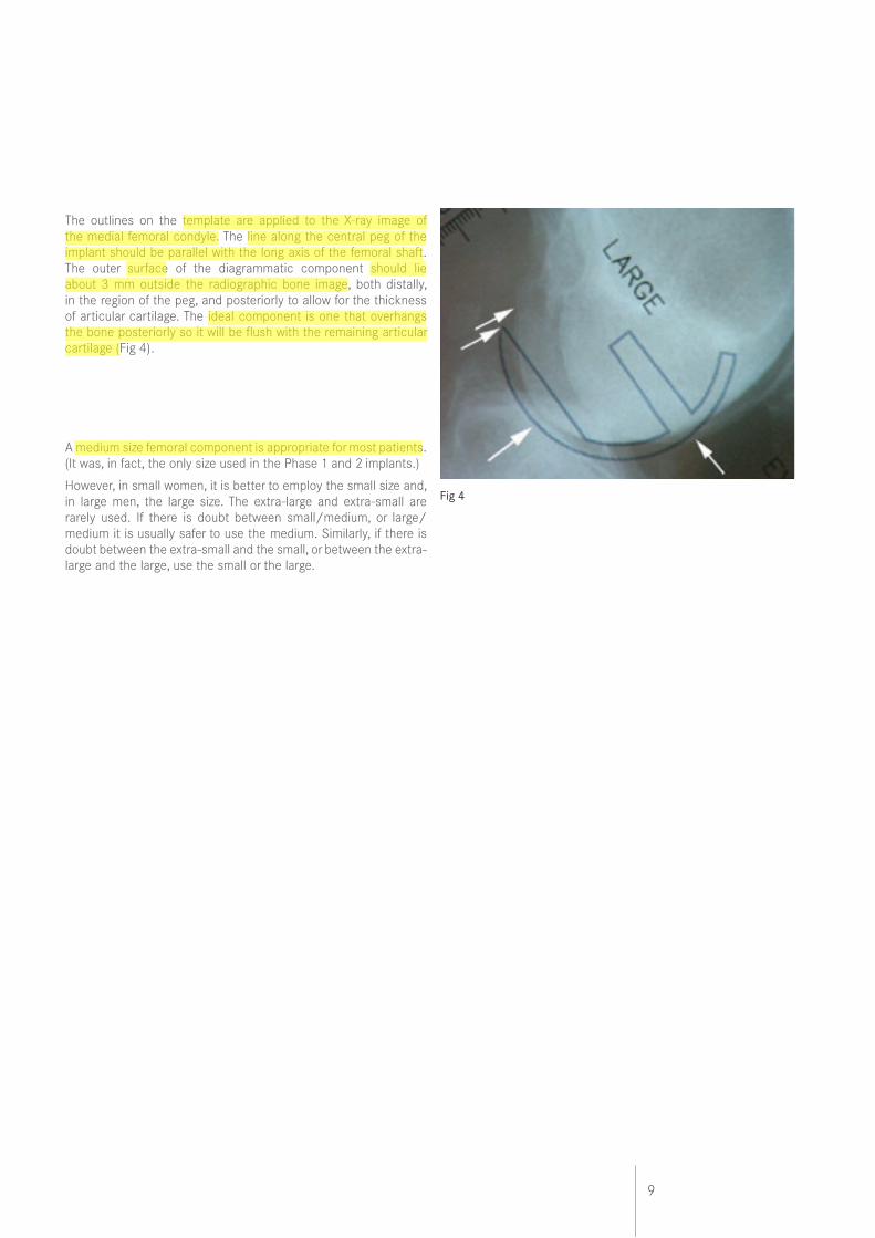
The outlines on the template are applied to the X-ray image of the medial femoral condyle. The line along the central peg of the implant should be parallel with the long axis of the femoral shaft. The outer surface of the diagrammatic component should lie about 3 mm outside the radiographic bone image, both distally, in the region of the peg, and posteriorly to allow for the thickness of articular cartilage. The ideal component is one that overhangs the bone posteriorly so it will be flush with the remaining articular cartilage (Fig 4).
A medium size femoral component is appropriate for most patients. (It was, in fact, the only size used in the Phase 1 and 2 implants.)
However, in small women, it is better to employ the small size and, in large men, the large size. The extra-large and extra-small are rarely used. If there is doubt between small/medium, or large/medium it is usually safer to use the medium. Similarly, if there is doubt between the extra-small and the small, or between the extra-large and the large, use the small or the large.
Fig 4
10
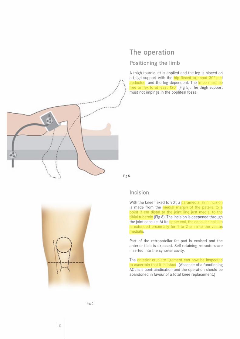
The operationPositioning the limb
A thigh tourniquet is applied and the leg is placed on a thigh support with the hip flexed to about 30º and abducted, and the leg dependent. The knee must be free to flex to at least 120º (Fig 5). The thigh support must not impinge in the popliteal fossa.
Incision
With the knee flexed to 90º, a paramedial skin incision is made from the medial margin of the patella to a point 3 cm distal to the joint line just medial to the tibial tubercle (Fig 6). The incision is deepened through the joint capsule. At its upper end, the capsular incision is extended proximally for 1 to 2 cm into the vastus medialis
Part of the retropatellar fat pad is excised and the anterior tibia is exposed. Self-retaining retractors are inserted into the synovial cavity.
The anterior cruciate ligament can now be inspected to ascertain that it is intact. (Absence of a functioning ACL is a contraindication and the operation should be abandoned in favour of a total knee replacement.)
Fig 6
Fig 5
11
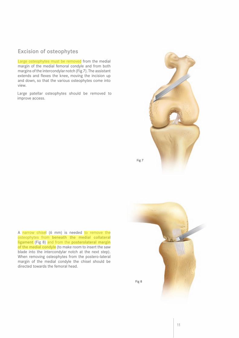
Excision of osteophytes
Large osteophytes must be removed from the medial margin of the medial femoral condyle and from both margins of the intercondylar notch (Fig 7). The assistant extends and flexes the knee, moving the incision up and down, so that the various osteophytes come into view.
A narrow chisel (6 mm) is needed to remove the osteophytes from beneath the medial collateral ligament (Fig 8) and from the posterolateral margin of the medial condyle (to make room to insert the saw blade into the intercondylar notch at the next step). When removing osteophytes from the postero-lateral margin of the medial condyle the chisel should be directed towards the femoral head.
Fig 7
Fig 8
Large patellar osteophytes should be removed to improve access.
12
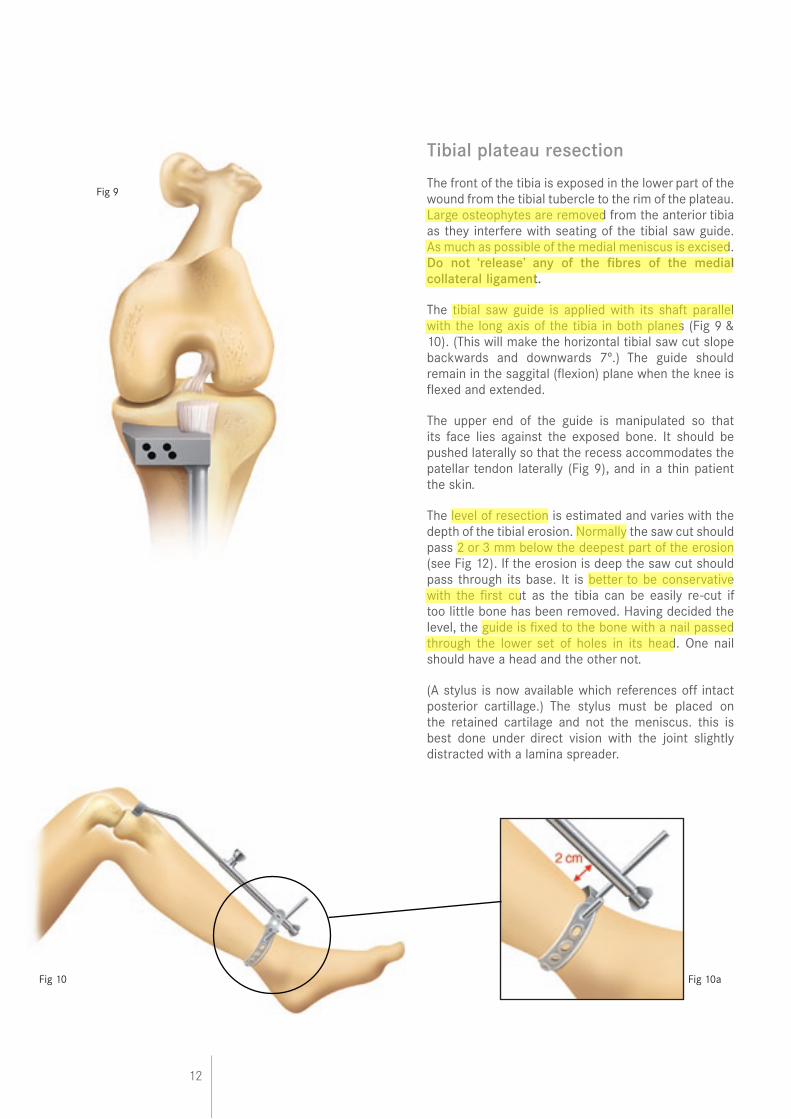
Tibial plateau resection
The front of the tibia is exposed in the lower part of the wound from the tibial tubercle to the rim of the plateau. Large osteophytes are removed from the anterior tibia as they interfere with seating of the tibial saw guide. As much as possible of the medial meniscus is excised. Do not ‘release’ any of the fibres of the medial collateral ligament.
The tibial saw guide is applied with its shaft parallel with the long axis of the tibia in both planes (Fig 9 & 10). (This will make the horizontal tibial saw cut slope backwards and downwards 7º.) The guide should remain in the saggital (flexion) plane when the knee is flexed and extended.
The upper end of the guide is manipulated so that its face lies against the exposed bone. It should be pushed laterally so that the recess accommodates the patellar tendon laterally (Fig 9), and in a thin patient the skin.
The level of resection is estimated and varies with the depth of the tibial erosion. Normally the saw cut should pass 2 or 3 mm below the deepest part of the erosion (see Fig 12). If the erosion is deep the saw cut should pass through its base. It is better to be conservative with the first cut as the tibia can be easily re-cut if too little bone has been removed. Having decided the level, the guide is fixed to the bone with a nail passed through the lower set of holes in its head. One nail should have a head and the other not.
(A stylus is now available which references off intact posterior cartillage.) The stylus must be placed on the retained cartilage and not the meniscus. this is best done under direct vision with the joint slightly distracted with a lamina spreader.
Fig 10
Fig 9
Fig 10a
13
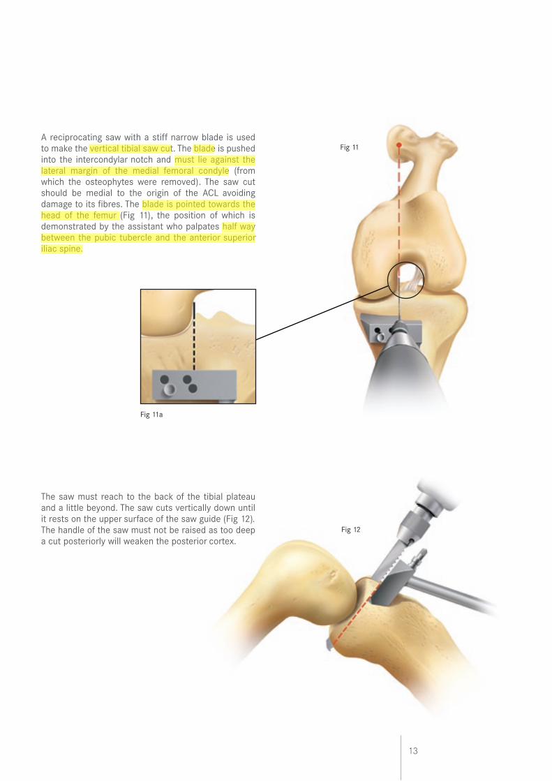
A reciprocating saw with a stiff narrow blade is used to make the vertical tibial saw cut. The blade is pushed into the intercondylar notch and must lie against the lateral margin of the medial femoral condyle (from which the osteophytes were removed). The saw cut should be medial to the origin of the ACL avoiding damage to its fibres. The blade is pointed towards the head of the femur (Fig 11), the position of which is demonstrated by the assistant who palpates half way between the pubic tubercle and the anterior superior iliac spine.
The saw must reach to the back of the tibial plateau and a little beyond. The saw cuts vertically down until it rests on the upper surface of the saw guide (Fig 12). The handle of the saw must not be raised as too deep a cut posteriorly will weaken the posterior cortex.
Fig 11
Fig 12
Fig 11a
14
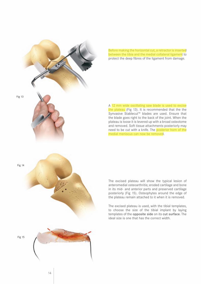
Before making the horizontal cut, a retractor is inserted between the tibia and the medial collateral ligament to protect the deep fibres of the ligament from damage.
A 12 mm wide oscillating saw blade is used to excise the plateau (Fig 13). It is recommended that the the Synvasive Stablecut™ blades are used. Ensure that the blade goes right to the back of the joint. When the plateau is loose it is levered up with a broad osteotome and removed. Soft tissue attachments posteriorly may need to be cut with a knife. The posterior horn of the medial meniscus can now be removed.
The excised plateau will show the typical lesion of anteromedial osteoarthritis; eroded cartilage and bone in its mid- and anterior parts and preserved cartilage posteriorly (Fig 15). Osteophytes around the edge of the plateau remain attached to it when it is removed.
The excised plateau is used, with the tibial templates, to choose the size of the tibial implant by laying templates of the opposite side on its cut surface. The ideal size is one that has the correct width.
Fig 14
Fig 15
Fig 13
15
Fig 17
Fig 16
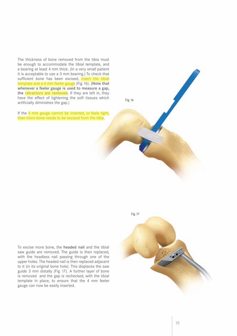
The thickness of bone removed from the tibia must be enough to accommodate the tibial template, and a bearing at least 4 mm thick. (In a very small patient it is acceptable to use a 3 mm bearing.) To check that sufficient bone has been excised, insert the tibial template and a 4 mm feeler gauge (Fig 16). (Note that whenever a feeler gauge is used to measure a gap, the retractors are removed. If they are left in, they have the effect of tightening the soft tissues which artificially diminishes the gap.)
If the 4 mm gauge cannot be inserted, or feels tight, then more bone needs to be excised from the tibia.
To excise more bone, the headed nail and the tibial saw guide are removed. The guide is then replaced, with the headless nail passing through one of the upper holes. The headed nail is then replaced adjacent to it (in its original bone hole). This displaces the saw guide 3 mm distally (Fig 17). A further layer of bone is removed and the gap is rechecked, with the tibial template in place, to ensure that the 4 mm feeler gauge can now be easily inserted.
16
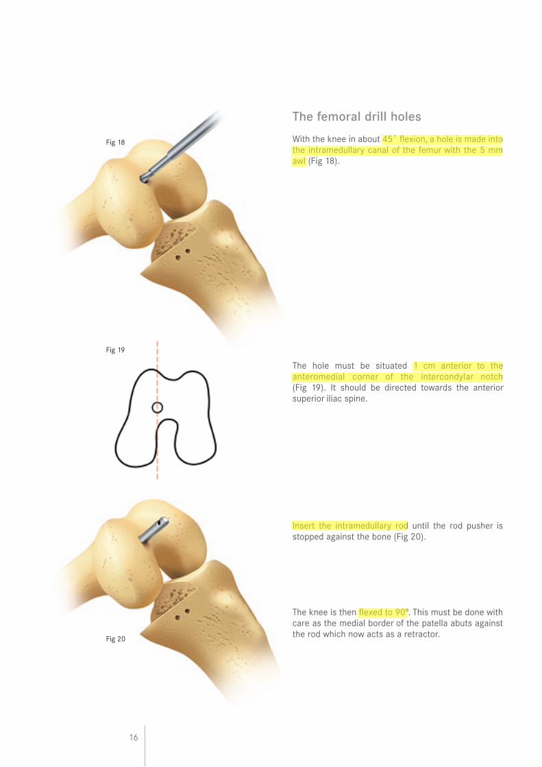
The femoral drill holes
With the knee in about 45˚ flexion, a hole is made into the intramedullary canal of the femur with the 5 mm awl (Fig 18).
The hole must be situated 1 cm anterior to the anteromedial corner of the intercondylar notch (Fig 19). It should be directed towards the anterior superior iliac spine.
Insert the intramedullary rod until the rod pusher is stopped against the bone (Fig 20).
The knee is then flexed to 90º. This must be done with care as the medial border of the patella abuts against the rod which now acts as a retractor.
Fig 18
Fig 19
Fig 20
17
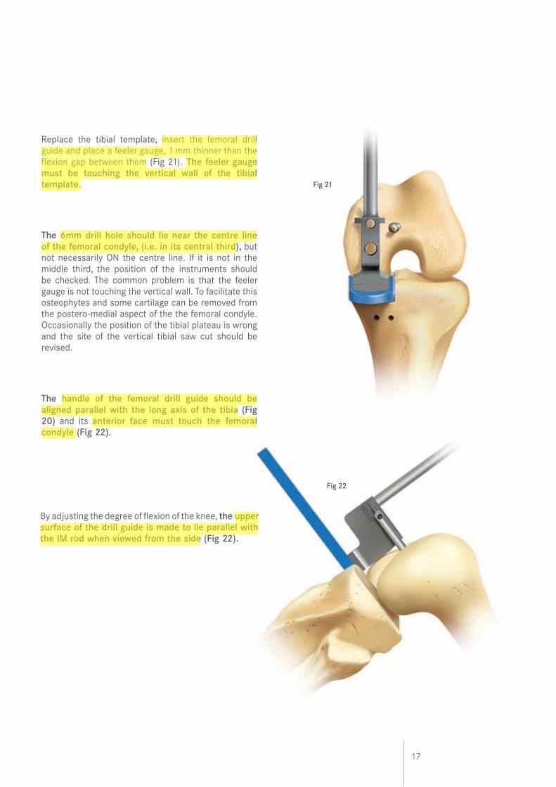
Replace the tibial template, insert the femoral drill guide and place a feeler gauge, 1 mm thinner than the flexion gap between them (Fig 21). The feeler gauge must be touching the vertical wall of the tibial template.
The 6mm drill hole should lie near the centre line of the femoral condyle, (i.e. in its central third), but not necessarily ON the centre line. If it is not in the middle third, the position of the instruments should be checked. The common problem is that the feeler gauge is not touching the vertical wall. To facilitate this osteophytes and some cartilage can be removed from the postero-medial aspect of the the femoral condyle. Occasionally the position of the tibial plateau is wrong and the site of the vertical tibial saw cut should be revised.
The handle of the femoral drill guide should be aligned parallel with the long axis of the tibia (Fig 20) and its anterior face must touch the femoral condyle (Fig 22).
Fig 21
Fig 22
By adjusting the degree of flexion of the knee, the upper surface of the drill guide is made to lie parallel with the IM rod when viewed from the side (Fig 22).
18
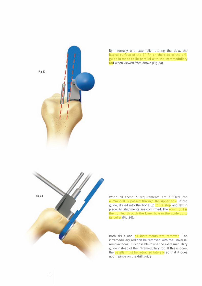
By internally and externally rotating the tibia, the lateral surface of the 7˚ fin on the side of the drill guide is made to lie parallel with the intramedullary rod when viewed from above (Fig 23).
When all these 6 requirements are fulfilled, the 4 mm drill is passed through the upper hole in the guide, drilled into the bone up to its stop and left in place. All alignments are confirmed. The 6 mm drill is then drilled through the lower hole in the guide up to its collar (Fig 24).
Both drills and all instruments are removed. The intramedullary rod can be removed with the universal removal hook. It is possible to use the extra medullary guide instead of the intramedullary rod. If this is done, the patella must be retracted laterally so that it does not impinge on the drill guide.
Fig 23
Fig 24
19
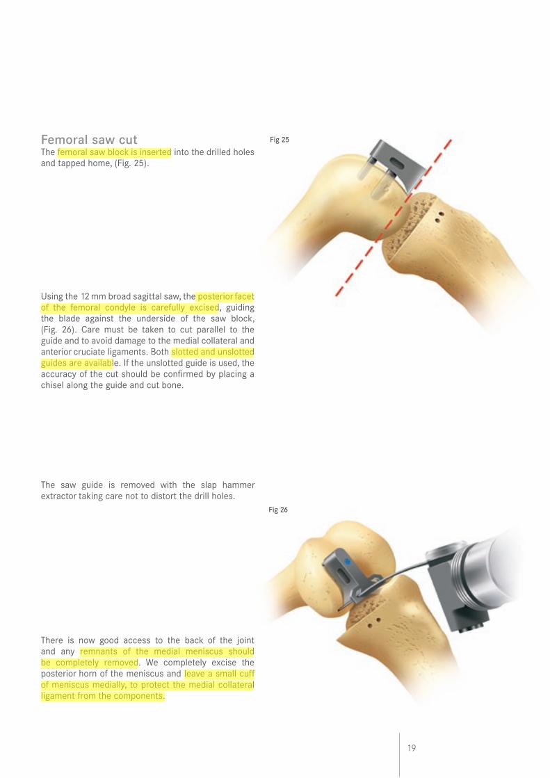
Femoral saw cutThe femoral saw block is inserted into the drilled holes and tapped home, (Fig. 25).
Using the 12 mm broad sagittal saw, the posterior facet of the femoral condyle is carefully excised, guiding the blade against the underside of the saw block, (Fig. 26). Care must be taken to cut parallel to the guide and to avoid damage to the medial collateral and anterior cruciate ligaments. Both slotted and unslotted guides are available. If the unslotted guide is used, the accuracy of the cut should be confirmed by placing a chisel along the guide and cut bone.
The saw guide is removed with the slap hammer extractor taking care not to distort the drill holes.
There is now good access to the back of the joint and any remnants of the medial meniscus should be completely removed. We completely excise the posterior horn of the meniscus and leave a small cuff of meniscus medially, to protect the medial collateral ligament from the components.
Fig 26
Fig 25
20
Fig 27
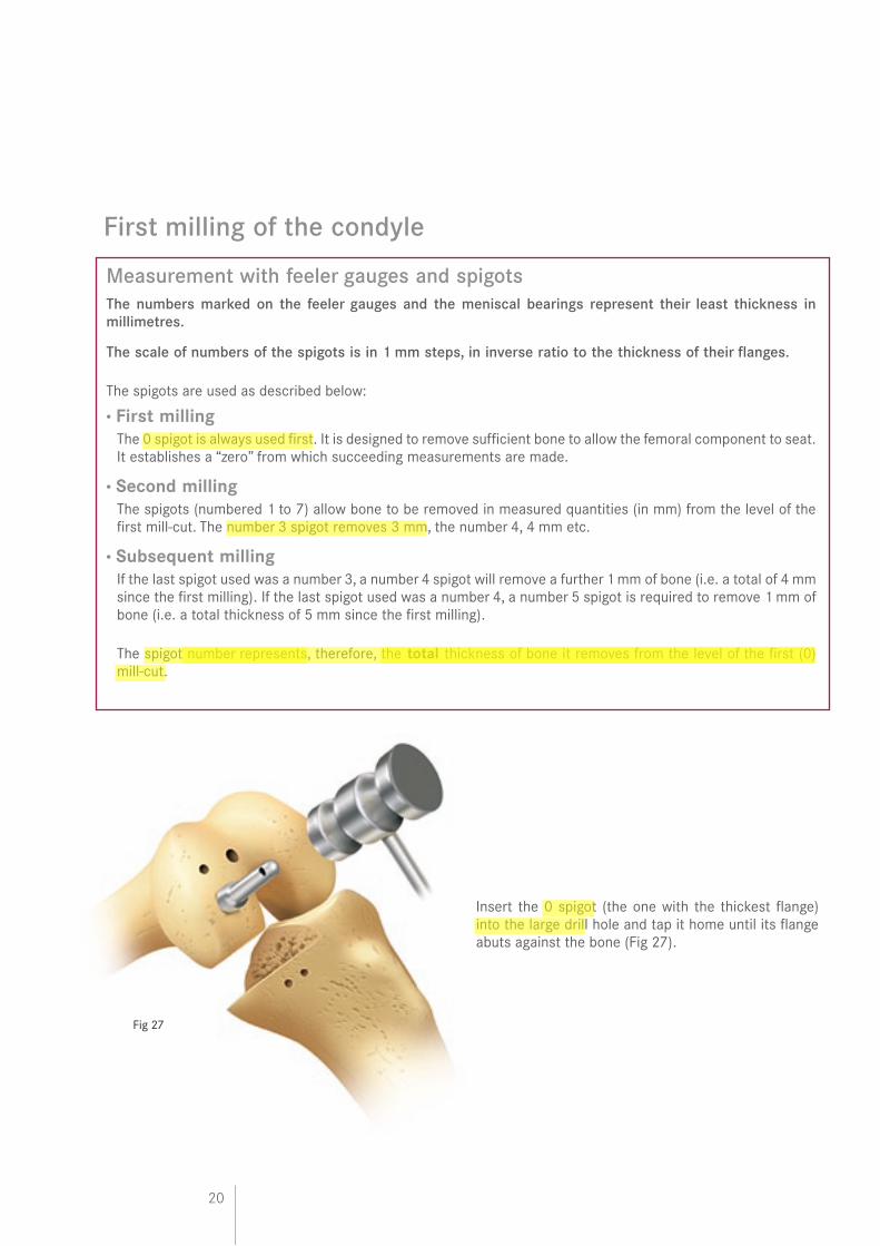
Insert the 0 spigot (the one with the thickest flange) into the large drill hole and tap it home until its flange abuts against the bone (Fig 27).
Measurement with feeler gauges and spigotsThe numbers marked on the feeler gauges and the meniscal bearings represent their least thickness in millimetres.
The scale of numbers of the spigots is in 1 mm steps, in inverse ratio to the thickness of their flanges.
The spigots are used as described below:
• First milling The 0 spigot is always used first. It is designed to remove sufficient bone to allow the femoral component to seat.
It establishes a “zero” from which succeeding measurements are made.
• Second milling The spigots (numbered 1 to 7) allow bone to be removed in measured quantities (in mm) from the level of the
first mill-cut. The number 3 spigot removes 3 mm, the number 4, 4 mm etc.
• Subsequent milling If the last spigot used was a number 3, a number 4 spigot will remove a further 1 mm of bone (i.e. a total of 4 mm
since the first milling). If the last spigot used was a number 4, a number 5 spigot is required to remove 1 mm of bone (i.e. a total thickness of 5 mm since the first milling).
The spigot number represents, therefore, the total thickness of bone it removes from the level of the first (0) mill-cut.
First milling of the condyle
21
Fig 29
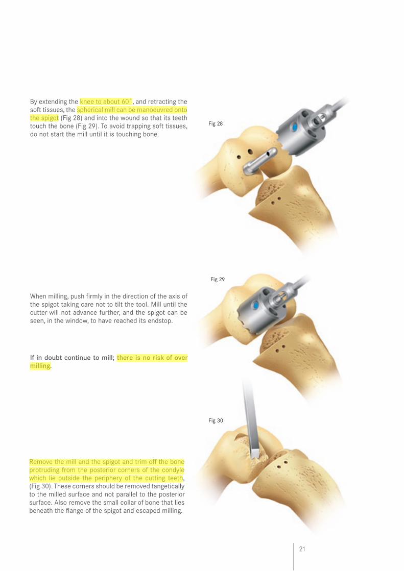
By extending the knee to about 60˚, and retracting the soft tissues, the spherical mill can be manoeuvred onto the spigot (Fig 28) and into the wound so that its teeth touch the bone (Fig 29). To avoid trapping soft tissues, do not start the mill until it is touching bone.
When milling, push firmly in the direction of the axis of the spigot taking care not to tilt the tool. Mill until the cutter will not advance further, and the spigot can be seen, in the window, to have reached its endstop.
If in doubt continue to mill; there is no risk of over milling.
Fig 28
Fig 30
Remove the mill and the spigot and trim off the bone protruding from the posterior corners of the condyle which lie outside the periphery of the cutting teeth, (Fig 30). These corners should be removed tangetically to the milled surface and not parallel to the posterior surface. Also remove the small collar of bone that lies beneath the flange of the spigot and escaped milling.
22
Equalising the 90˚ and 20˚ flexion gaps
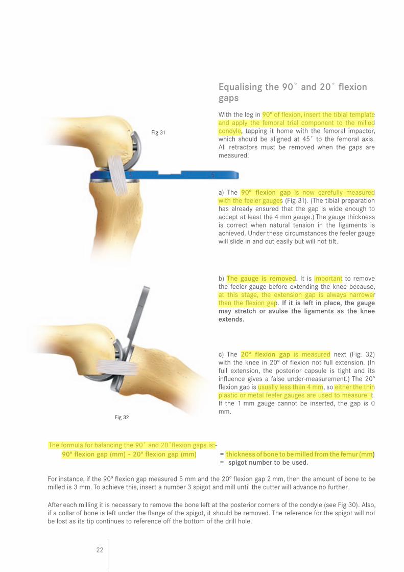
With the leg in 90º of flexion, insert the tibial template and apply the femoral trial component to the milled condyle, tapping it home with the femoral impactor, which should be aligned at 45˚ to the femoral axis. All retractors must be removed when the gaps are measured.
a) The 90º flexion gap is now carefully measured with the feeler gauges (Fig 31). (The tibial preparation has already ensured that the gap is wide enough to accept at least the 4 mm gauge.) The gauge thickness is correct when natural tension in the ligaments is achieved. Under these circumstances the feeler gauge will slide in and out easily but will not tilt.
b) The gauge is removed. It is important to remove the feeler gauge before extending the knee because, at this stage, the extension gap is always narrower than the flexion gap. If it is left in place, the gauge may stretch or avulse the ligaments as the knee extends.
c) The 20º flexion gap is measured next (Fig. 32) with the knee in 20º of flexion not full extension. (In full extension, the posterior capsule is tight and its influence gives a false under-measurement.) The 20º flexion gap is usually less than 4 mm, so either the thin plastic or metal feeler gauges are used to measure it. If the 1 mm gauge cannot be inserted, the gap is 0 mm.
The formula for balancing the 90˚ and 20˚flexion gaps is:- 90º flexion gap (mm) - 20º flexion gap (mm) = thickness of bone to be milled from the femur (mm) = spigot number to be used.
Fig 31
Fig 32
For instance, if the 90º flexion gap measured 5 mm and the 20º flexion gap 2 mm, then the amount of bone to be milled is 3 mm. To achieve this, insert a number 3 spigot and mill until the cutter will advance no further.
After each milling it is necessary to remove the bone left at the posterior corners of the condyle (see Fig 30). Also, if a collar of bone is left under the flange of the spigot, it should be removed. The reference for the spigot will not be lost as its tip continues to reference off the bottom of the drill hole.
23
Fig 34
Confirming equality of the 90˚and 20˚flexion gaps
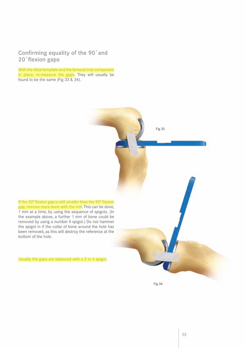
With the tibial template and the femoral trial component in place, re-measure the gaps. They will usually be found to be the same (Fig 33 & 34).
If the 20º flexion gap is still smaller than the 90º flexion gap, remove more bone with the mill. This can be done, 1 mm at a time, by using the sequence of spigots. (In the example above, a further 1 mm of bone could be removed by using a number 4 spigot.) Do not hammer the spigot in if the collar of bone around the hole has been removed, as this will destroy the reference at the bottom of the hole.
Usually the gaps are balanced with a 3 or 4 spigot.
Fig 33
24
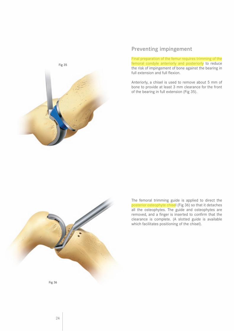
Preventing impingement
Final preparation of the femur requires trimming of the femoral condyle anteriorly and posteriorly to reduce the risk of impingement of bone against the bearing in full extension and full flexion.
Anteriorly, a chisel is used to remove about 5 mm of bone to provide at least 3 mm clearance for the front of the bearing in full extension (Fig 35).
The femoral trimming guide is applied to direct the posterior osteophyte chisel (Fig 36) so that it detaches all the osteophytes. The guide and osteophytes are removed, and a finger is inserted to confirm that the clearance is complete. (A slotted guide is available which facilitates positioning of the chisel).
Fig 35
Fig 36
25
Final preparation of the tibial plateau
The tibial plateau is examined to ensure that there are no large marginal osteophytes medially. If there are, they should be removed taking care not to damage the MCL.
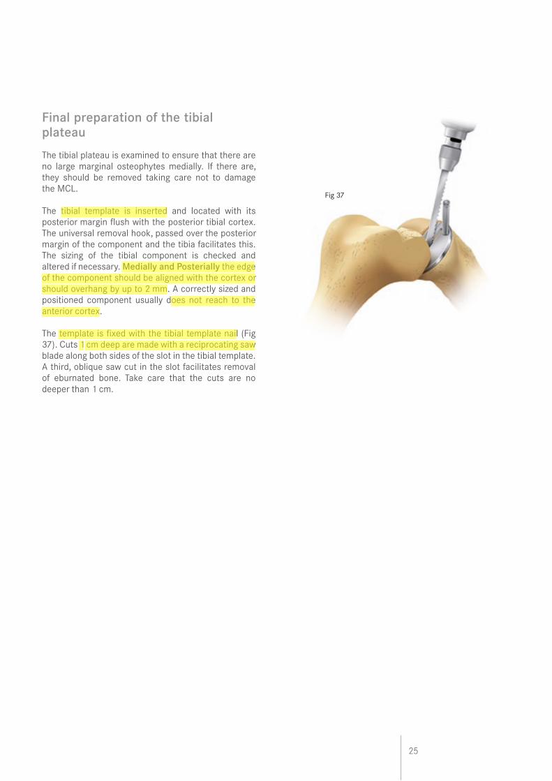
The tibial template is inserted and located with its posterior margin flush with the posterior tibial cortex. The universal removal hook, passed over the posterior margin of the component and the tibia facilitates this. The sizing of the tibial component is checked and altered if necessary. Medially and Posterially the edge of the component should be aligned with the cortex or should overhang by up to 2 mm. A correctly sized and positioned component usually does not reach to the anterior cortex.
The template is fixed with the tibial template nail (Fig 37). Cuts 1 cm deep are made with a reciprocating saw blade along both sides of the slot in the tibial template. A third, oblique saw cut in the slot facilitates removal of eburnated bone. Take care that the cuts are no deeper than 1 cm.
Fig 37
26
Fig 39
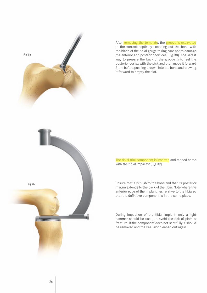
After removing the template, the groove is excavated to the correct depth by scooping out the bone with the blade of the tibial gouge taking care not to damage the anterior and posterior cortices (Fig 38). The safest way to prepare the back of the groove is to feel the posterior cortex with the pick and then move it forward 5mm before pushing it down into the bone and drawing it forward to empty the slot.
The tibial trial component is inserted and tapped home with the tibial impactor (Fig 39).
Ensure that it is flush to the bone and that its posterior margin extends to the back of the tibia. Note where the anterior edge of the implant lies relative to the tibia so that the definitive component is in the same place.
During impaction of the tibial implant, only a light hammer should be used, to avoid the risk of plateau fracture. If the component does not seat fully it should be removed and the keel slot cleaned out again.
Fig 38
27
Trial reduction
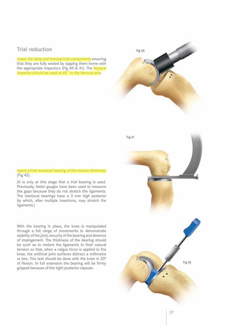
Insert the tibial and femoral trial components ensuring that they are fully seated by tapping them home with the appropriate impactors (Fig 40 & 41). The femoral impactor should be used at 45˚ to the femoral axis.
Insert a trial meniscal bearing of the chosen thickness (Fig 42).
(It is only at this stage that a trial bearing is used. Previously, feeler gauges have been used to measure the gaps because they do not stretch the ligaments. The meniscal bearings have a 3 mm high posterior lip which, after multiple insertions, may stretch the ligaments.)
With the bearing in place, the knee is manipulated through a full range of movements to demonstrate stability of the joint, security of the bearing and absence of impingement. The thickness of the bearing should be such as to restore the ligaments to their natural tension so that, when a valgus force is applied to the knee, the artificial joint surfaces distract a millimetre or two. This test should be done with the knee in 20º of flexion. In full extension the bearing will be firmly gripped because of the tight posterior capsule.
Fig 40
Fig 41
Fig 42
28
Fig 44
Fig 43
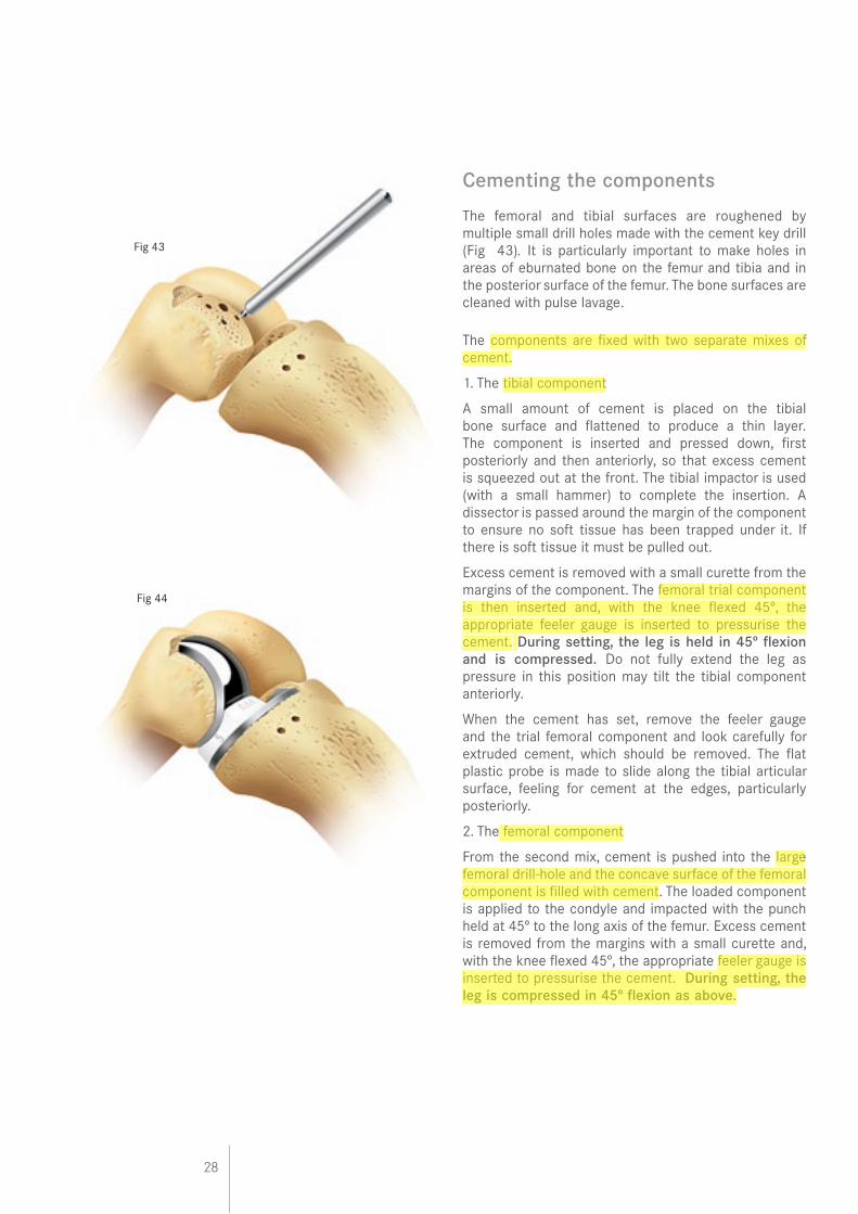
Cementing the components
The femoral and tibial surfaces are roughened by multiple small drill holes made with the cement key drill (Fig 43). It is particularly important to make holes in areas of eburnated bone on the femur and tibia and in the posterior surface of the femur. The bone surfaces are cleaned with pulse lavage.
The components are fixed with two separate mixes of cement.
1. The tibial component
A small amount of cement is placed on the tibial bone surface and flattened to produce a thin layer. The component is inserted and pressed down, first posteriorly and then anteriorly, so that excess cement is squeezed out at the front. The tibial impactor is used (with a small hammer) to complete the insertion. A dissector is passed around the margin of the component to ensure no soft tissue has been trapped under it. If there is soft tissue it must be pulled out.
Excess cement is removed with a small curette from the margins of the component. The femoral trial component is then inserted and, with the knee flexed 45º, the appropriate feeler gauge is inserted to pressurise the cement. During setting, the leg is held in 45º flexion and is compressed. Do not fully extend the leg as pressure in this position may tilt the tibial component anteriorly.
When the cement has set, remove the feeler gauge and the trial femoral component and look carefully for extruded cement, which should be removed. The flat plastic probe is made to slide along the tibial articular surface, feeling for cement at the edges, particularly posteriorly.
2. The femoral component
From the second mix, cement is pushed into the large femoral drill-hole and the concave surface of the femoral component is filled with cement. The loaded component is applied to the condyle and impacted with the punch held at 45º to the long axis of the femur. Excess cement is removed from the margins with a small curette and, with the knee flexed 45º, the appropriate feeler gauge is inserted to pressurise the cement. During setting, the leg is compressed in 45º flexion as above.
29
Fig 45
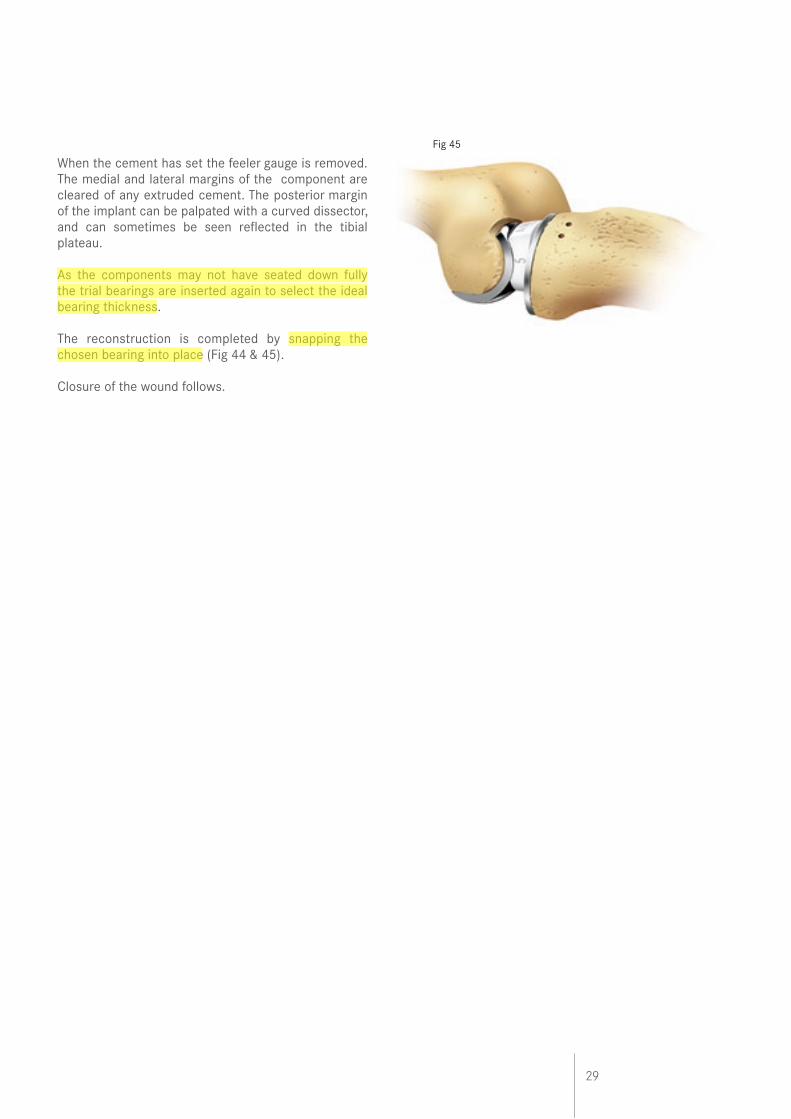
When the cement has set the feeler gauge is removed. The medial and lateral margins of the component are cleared of any extruded cement. The posterior margin of the implant can be palpated with a curved dissector, and can sometimes be seen reflected in the tibial plateau.
As the components may not have seated down fully the trial bearings are inserted again to select the ideal bearing thickness.
The reconstruction is completed by snapping the chosen bearing into place (Fig 44 & 45).
Closure of the wound follows.
30
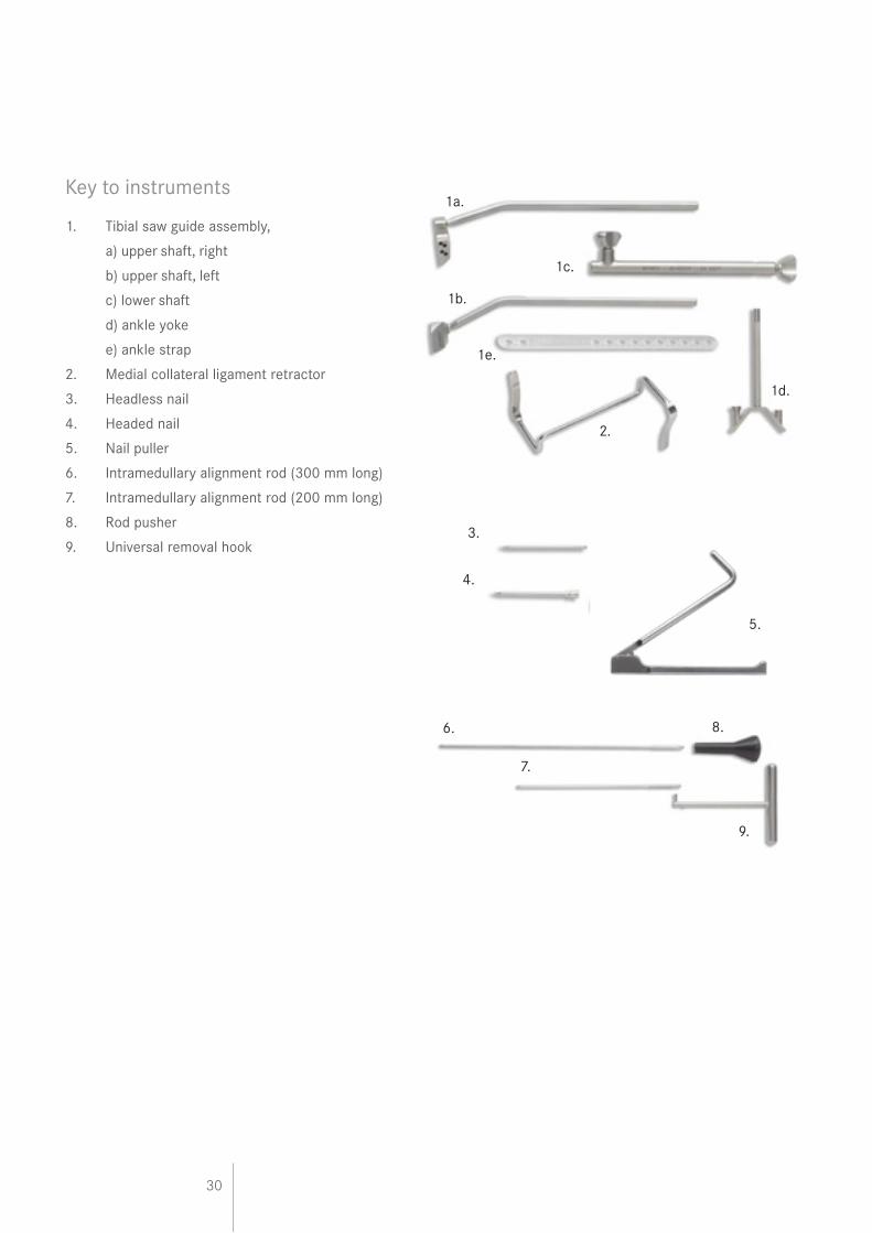
Key to instruments
1. Tibial saw guide assembly,
a) upper shaft, right
b) upper shaft, left
c) lower shaft
d) ankle yoke
e) ankle strap
2. Medial collateral ligament retractor
3. Headless nail
4. Headed nail
5. Nail puller
6. Intramedullary alignment rod (300 mm long)
7. Intramedullary alignment rod (200 mm long)
8. Rod pusher
9. Universal removal hook
1a.
2.
1d.
1c.
3.
6.
7.
1b.
1e.
4.
5.
8.
9.
31
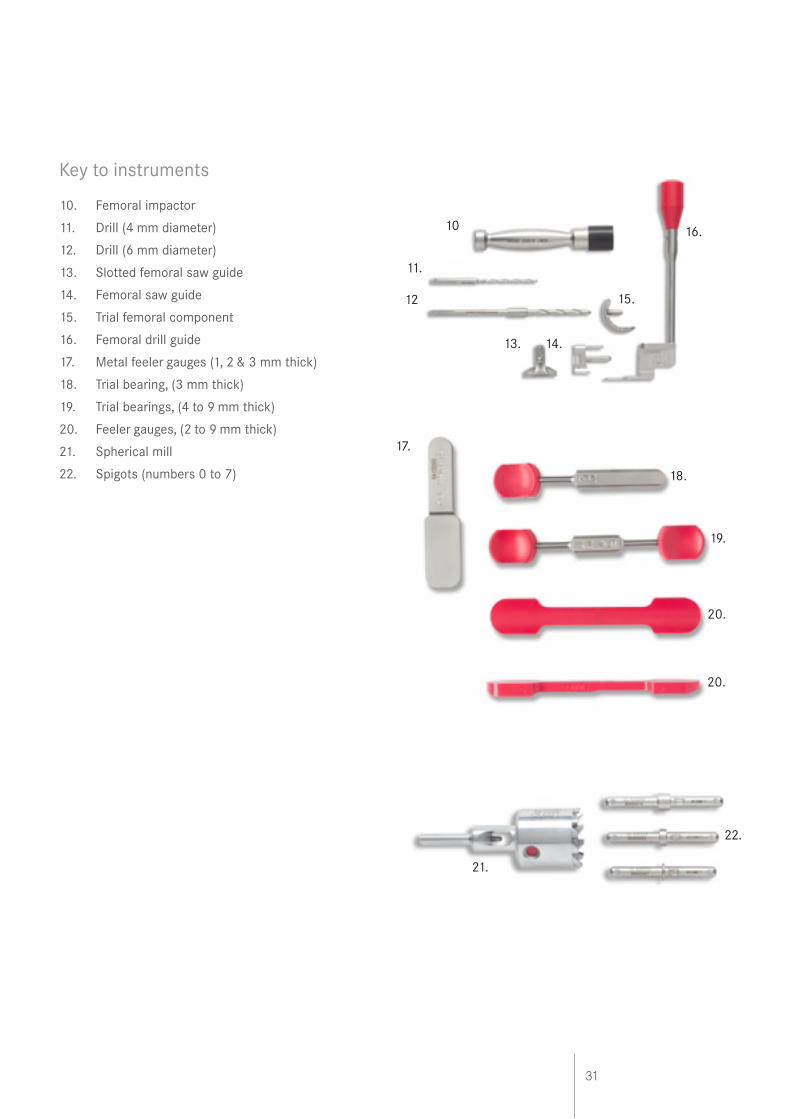
Key to instruments
10. Femoral impactor
11. Drill (4 mm diameter)
12. Drill (6 mm diameter)
13. Slotted femoral saw guide
14. Femoral saw guide
15. Trial femoral component
16. Femoral drill guide
17. Metal feeler gauges (1, 2 & 3 mm thick)
18. Trial bearing, (3 mm thick)
19. Trial bearings, (4 to 9 mm thick)
20. Feeler gauges, (2 to 9 mm thick)
21. Spherical mill
22. Spigots (numbers 0 to 7)
17.
18.
19.
20.
20.
10
11.
12 15.
13. 14.
16.
21.
22.
32
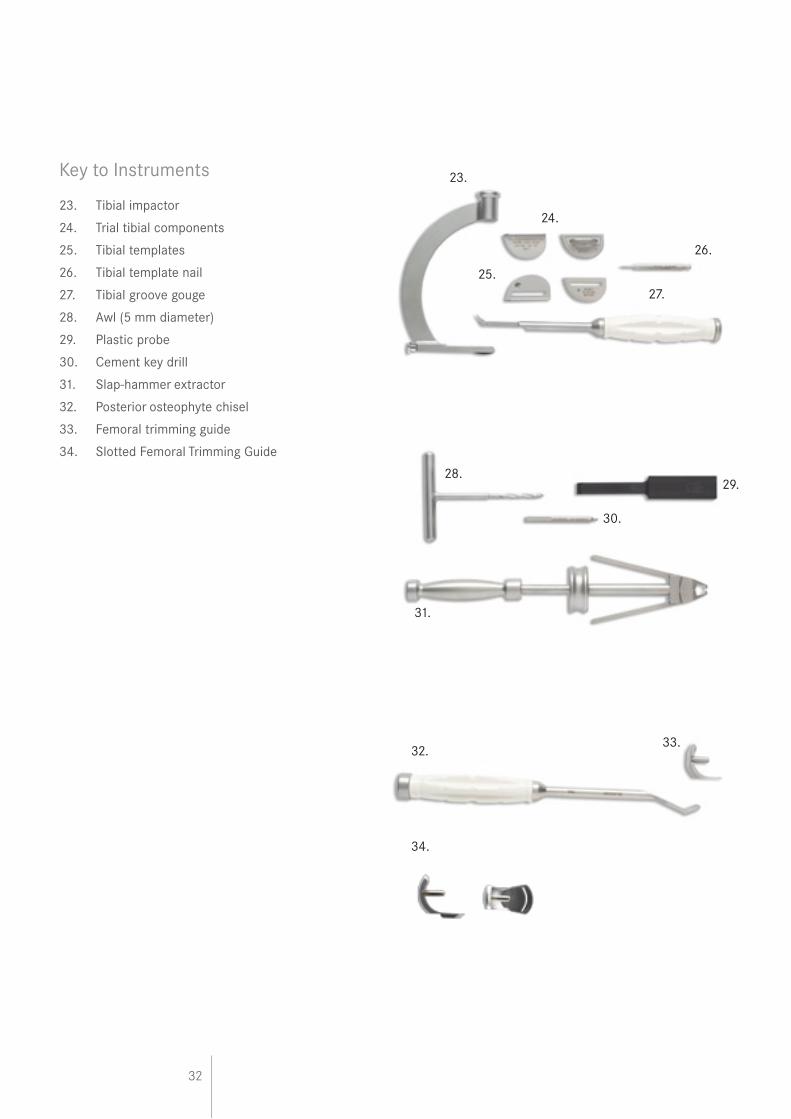
Key to Instruments
23. Tibial impactor
24. Trial tibial components
25. Tibial templates
26. Tibial template nail
27. Tibial groove gouge
28. Awl (5 mm diameter)
29. Plastic probe
30. Cement key drill
31. Slap-hammer extractor
32. Posterior osteophyte chisel
33. Femoral trimming guide
34. Slotted Femoral Trimming Guide
23.
24.
25.
26.
27.
28.29.
30.
31.
32.33.
34.
33
References
1. Goodfellow JW, O’Connor JJ. The Mechanics of the Knee and Prosthesis Design. J Bone Joint Surg [Br] 1978;No.3;60-B:358-369.
2. Argenson J-N, O’Connor JJ. Polyethylene Wear in Meniscal Knee Replacement. A One to Nine-Year Retrieval Analysis of the Oxford Knee. J Bone Joint Surgery [Br] 1992;74-B:228-32
3. Psychoyios V, Crawford RW, O’Connor JJ, Murray DW. Wear of congruent meniscal bearings in unicompartmental knee arthroplasty - A retrieval study of 16 specimen. J Bone Joint Surg [Br] 1998;No.6;80-B:976-982.
4. White SH, Goodfellow JW, O’Connor JJ. Anteromedial Osteoarthritis of the Knee. J Bone Joint Surg [Br] 1991;73-B:582-586.
5. Murray DW, O’Connor JJ, Goodfellow JW. The Oxford medial unicompartmental arthroplasty, a ten year survival study. J Bone Joint Surg [Br] 1998;No.6;80-B:983-989.
6. Price A, Svard U, Murray DW, Goodfellow JW. Ten year survival results of Oxford mobile bearing unicompartmental knee arthroplasty in young patients. I.S.T.A Chicago, 1999.
7. Incavo et al. Tibial Plateau Coverage in Total Knee Arthroplasty. Clin Orthop 1994;81-85.
8. Keys GW, Carr AJ, Miller RK, Goodfellow J. The Radiographic Classification of Medial Gonarthrosis. Correlation with Operative Methods in 200 Knees. Acta Orthop Scand 1992;63 (5); 497 - 501.
9. Gibson P, Goodfellow JW. Stress Radiography in Degenerative Arthritis of the Knee. J Bone J Surg [Br] 1986;68-B:608-9
10. Price AJ, Dodd CAF, Svard UGC & Murray DW, “Oxford unicompartmental arthroplasty in patients younger than 60 years of age” JBJS (Br) 2005, 87-B; 1488-92
11. Pandit HG, Price AJ, Rees JC, Beard DJ, Gill HS, Dodd CAF, Murray DW. Is unicompartmental knee arthroplasty contraindicated in young active patients JBJS 2004; 86-B; Suppl 1): 12
12. Woods D, Wallas D, Woods C, McLardy-Smith P, Carr AJ, Murray DW, Martin J, Gunther T. Chondrocalcinosis and medial unicompartmental knee arthroplasty. Knee 1995; 2: 117-19
13. Svärd UCG, Price AJ. Oxford medial unicompartmental knee arthroplasty – A survival analysis of an independent series. J Bone Joint Surg [Br] 2001; 83-B: 191-194.
14. Langdown, Pandit, Price, Dodd, Murrey, Svard, Gibbons Oxford medial unicompartmental arthroplasty for focal spontaneous osteoarthritis of the knee. Acta Orthop 2005; 76: 688-92
15. Pandit H, Beard DJ, Jenkins C, Kimstra Y, Thomas NP, Dodd CAF, Murray DW Combined anterior cruciate reconstruction and Oxford unicompartmental knee arthroplasty. JBJS 2006; 88-B:887-892
16. Gunther TV, Murray DW, Miller R, Wallace DA, Carr AJ, O’Connor JJ, McLardy Smith P, Goodfellow JW. Lateral unicompartmental arthroplasty with the Oxford meniscal knee. The Knee ;No.3; 33-39
17. Tibrewal SB, Grant KA, Goodfellow JW. The Radiolucent Line beneath the Tibial Components of the Oxford Meniscal Knee. JBJS 1984;66-B:523-8
18 . Weale AE, Murray DW, Crawford RW, Psychoyios V, Bonomo A, Howell G, O’Connor JJ, Goodfellow JW. Does Arthritis Progress in the Retained Compartments after ‘Oxford’ Medial Unicompartmental Arthroplasty? J Bone Joint Surg [Br] 1999;81-B:783-789.
34
Appendix
Postoperative Treatment
Because the quadriceps mechanism is hardly damaged, recovery of knee function is usually rapid and easy. Early walking with a light knee splint and crutches or sticks is encouraged and patients are allowed to regain knee flexion at their own speed. Forcing flexion of the knee during the first postoperative week often causes pain and is unnecessary since movements are almost always recovered spontaneously.
Postoperative Radiographic Assessment
Good postoperative radiographs are necessary as a baseline for comparison with later films and to allow ‘quality control’ of the surgical technique.For these purposes, the standard methods of aligning the X-ray beam are not sufficiently accurate, nor repeatable enough. To assess the positions of the two metal components, the X-ray beam must be centred on one component and aligned with it in two planes. The resulting projection of the other component can then be used to deduce their relative positions17.
Radiographic Technique
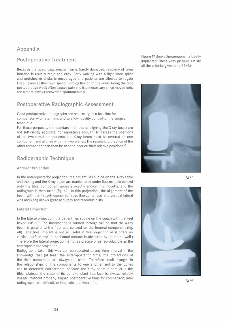
Anterior Projection
In the anteroposterior projection, the patient lies supine on the X-ray table and the leg and the X-ray beam are manipulated under fluoroscopic control until the tibial component appears exactly end-on in silhouette, and the radiograph is then taken (fig. 47). In this projection , the alignment of the beam with the flat orthogonal surfaces (horizontal tray and vertical lateral wall and keel) allows great accuracy and reproducibility.
Lateral Projection
In the lateral projection, the patient lies supine on the couch with the keel flexed 20°-30°. The fluoroscope is rotated through 90° so that the X-ray beam is parallel to the floor and centred on the femoral component (fig. 48). (The tibial implant is not so useful in this projection as it offers no vertical surface and its horizontal surface is obscured by its lateral wall.) Therefore the lateral projection is not as precise or as reproducible as the anteroposterior projection.Radiographs taken this way can be repeated at any time interval in the knowledge that (at least the anteroposterior films) the projections of the tibial component are always the same. Therefore small changes in the relationships of the components to one another and to the bones can be detected. Furthermore, because the X-ray beam is parallel to the tibial plateau, the state of its bone/implant interface is always reliably imaged. Without properly aligned postoperative films for comparison, later radiographs are difficult, or impossible, to interpret.
Figure 47 shows the components ideally implanted. These x-ray pictures satisfy all the criteria, given on p.35+36
fig.47
fig.48
35
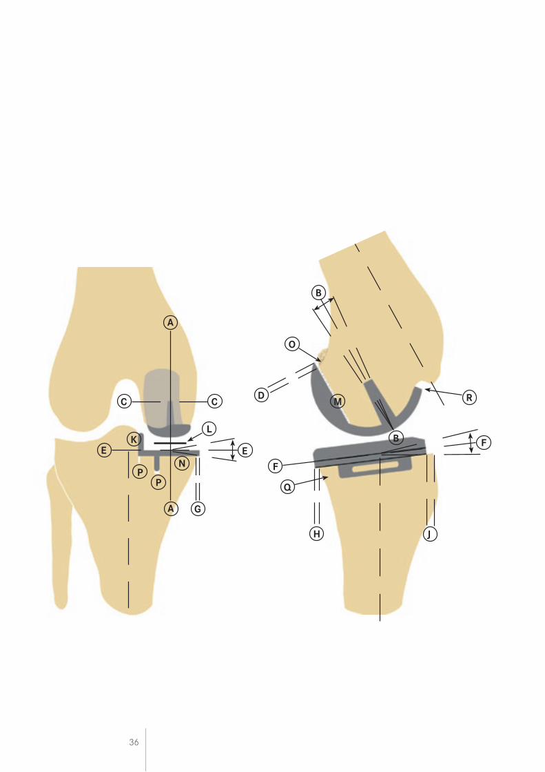
Radiographic Criteria
If the steps of the operation have all been followed as described in this manual, the postoperative appearances will be as shown here.
Position and Size of Components
Femoral Component (Relative to the Femur) Acceptable limits
A/A Varus/valgus angle <10º varus— <10º valgus
B/B Flexion/extension angle <10º flexion— <5º extension
C/C Medial/ lateral placement Central
D Posterior fit Flush or <4mm overhang
Tibial Component (Relative to the Tibia)
E/E Varus/valgus angle <5º varus— <5º valgus
F/F Posteroinferior tilt 7º +or- 5º
G Medial fit Flush or <2 mm overhang
H Posterior fit Flush or <2 mm overhang
J Anterior fit Flush or <5 mm short
K Lateral fit Flush - No gap
Meniscal Bearing (Relative to the Tibial Component) L X-ray marker central, and parallel with the tibial component
Bone Interfaces
M Posterior femoral Parallel surfaces: Cement OK N Tibial Parallel surfaces: Cement OK
Other
O Posterior osteophytes None visible P Depth of tibial saw cuts Minimal ingress of cement Q Intact posterior cortex No extruded cement posteriorly R No anterior impingement Adequate bone removed; no cement
36
A
CC
LK
EE
PP
N
A G
F
Q
H J
F
D
O
B
M
B
R
37
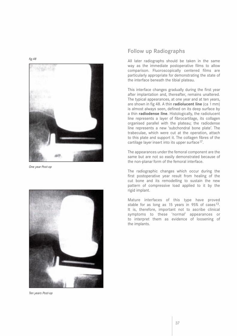
Follow up Radiographs
All later radiographs should be taken in the same way as the immediate postoperative films to allow comparison. Fluoroscopically centered films are particularly appropriate for demonstrating the state of the interface beneath the tibial plateau.
This interface changes gradually during the first year after implantation and, thereafter, remains unaltered. The typical appearances, at one year and at ten years, are shown in fig 48. A thin radiolucent line (ca 1 mm) is almost always seen, defined on its deep surface by a thin radiodense line. Histologically, the radiolucent line represents a layer of fibrocartilage, its collagen organised parallel with the plateau; the radiodense line represents a new ‘subchondral bone plate’. The trabeculae, which were cut at the operation, attach to this plate and support it. The collagen fibres of the cartilage layer insert into its upper surface17.
The appearances under the femoral component are the same but are not so easily demonstrated because of the non-planar form of the femoral interface.
The radiographic changes which occur during the first postoperative year result from healing of the cut bone and its remodelling to sustain the new pattern of compressive load applied to it by the rigid implant.
Mature interfaces of this type have proved stable for as long as 15 years in 95% of cases13. It is, therefore, important not to ascribe clinical symptoms to these ‘normal’ appearances or to interpret them as evidence of loosening of the implants.
fig.48
One year Post-op
Ten years Post-op
38
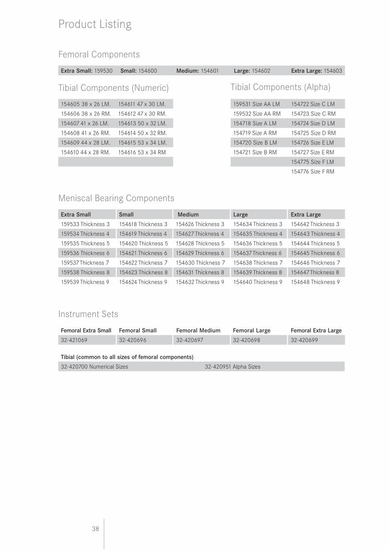
Product Listing
Femoral Components
Extra Small: 159530 Small: 154600 Medium: 154601 Large: 154602 Extra Large: 154603
Tibial Components (Numeric)
154605 38 x 26 LM. 154611 47 x 30 LM. 159531 Size AA LM 154722 Size C LM
154606 38 x 26 RM. 154612 47 x 30 RM. 159532 Size AA RM 154723 Size C RM
154607 41 x 26 LM. 154613 50 x 32 LM. 154718 Size A LM 154724 Size D LM
154608 41 x 26 RM. 154614 50 x 32 RM. 154719 Size A RM 154725 Size D RM
154609 44 x 28 LM. 154615 53 x 34 LM. 154720 Size B LM 154726 Size E LM
154610 44 x 28 RM. 154616 53 x 34 RM 154721 Size B RM 154727 Size E RM
154775 Size F LM
154776 Size F RM
Meniscal Bearing Components
Extra Small Small Medium Large Extra Large
159533 Thickness 3 154618 Thickness 3 154626 Thickness 3 154634 Thickness 3 154642 Thickness 3
159534 Thickness 4 154619 Thickness 4 154627 Thickness 4 154635 Thickness 4 154643 Thickness 4
159535 Thickness 5 154620 Thickness 5 154628 Thickness 5 154636 Thickness 5 154644 Thickness 5
159536 Thickness 6 154621 Thickness 6 154629 Thickness 6 154637 Thickness 6 154645 Thickness 6
159537 Thickness 7 154622 Thickness 7 154630 Thickness 7 154638 Thickness 7 154646 Thickness 7
159538 Thickness 8 154623 Thickness 8 154631 Thickness 8 154639 Thickness 8 154647 Thickness 8
159539 Thickness 9 154624 Thickness 9 154632 Thickness 9 154640 Thickness 9 154648 Thickness 9
Instrument Sets
Femoral Extra Small Femoral Small Femoral Medium Femoral Large Femoral Extra Large
32-421069 32-420696 32-420697 32-420698 32-420699
Tibial (common to all sizes of femoral components)
32-420700 Numerical Sizes 32-420951 Alpha Sizes
Tibial Components (Alpha)
39
Small LEFT Medium LEFT Large LEFT Extra-Large LEFT
159540 Thickness 3 159547 Thickness 3 159554 Thickness 3 159561 Thickness 3
159541 Thickness 4 159548 Thickness 4 159555 Thickness 4 159562 Thickness 4
159542 Thickness 5 159549 Thickness 5 159556 Thickness 5 159563 Thickness 5
159543 Thickness 6 159550 Thickness 6 159557 Thickness 6 159564 Thickness 6
159544 Thickness 7 159551 Thickness 7 159558 Thickness 7 159565 Thickness 7
159545 Thickness 8 159552 Thickness 8 159559 Thickness 8 159566 Thickness 8
159546 Thickness 9 159553 Thickness 9 159560 Thickness 9 159567 Thickness 9
Small RIGHT Medium RIGHT Large RIGHT ExtraLarge RIGHT
159568 Thickness 3 159575 Thickness 3 159582 Thickness 3 159589 Thickness 3
159569 Thickness 4 159576 Thickness 4 159583 Thickness 4 159590 Thickness 4
159570 Thickness 5 159577 Thickness 5 159584 Thickness 5 159591 Thickness 5
159571 Thickness 6 159578 Thickness 6 159585 Thickness 6 159592 Thickness 6
159572 Thickness 7 159579 Thickness 7 159586 Thickness 7 159593 Thickness 7
159573 Thickness 8 159580 Thickness 8 159587 Thickness 8 159594 Thickness 8
159574 Thickness 9 159581 Thickness 9 159588 Thickness 9 159595 Thickness 9
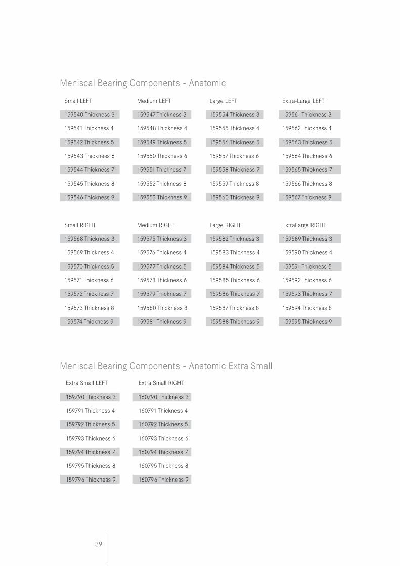
Meniscal Bearing Components - Anatomic
Extra Small LEFT Extra Small RIGHT
159790 Thickness 3 160790 Thickness 3
159791 Thickness 4 160791 Thickness 4
159792 Thickness 5 160792 Thickness 5
159793 Thickness 6 160793 Thickness 6
159794 Thickness 7 160794 Thickness 7
159795 Thickness 8 160795 Thickness 8
159796 Thickness 9 160796 Thickness 9
Meniscal Bearing Components - Anatomic Extra Small

40
Biomet UK Ltd
Waterton Industrial Estate
Bridgend, South Wales
CF31 3XA, United Kingdom
Tel. +44 (0)1656 655221Fax. +44 (0)1656 645454
www.biomet.co.uk
FLK0
89 1
1/07
www.oxfordknee.net