Embed Size (px)
Citation preview

10/18/16 PN 96377 v.12.0
Banks Power Pack®
SystemIncluding Banks Stinger® System Banks TorqueTube System
2006-2015 Ford 6.8L V-10 Class-A Motorhome THIS MANUAL IS FOR USE WITH SYSTEMS 49170-49172, 49175, 49176, 49177
Gale Banks Engineering 546 Duggan Avenue • Azusa, CA 91702 (626) 969-9600 • Fax (626) 334-1743
Product Information & Sales: (888) 635-4565Customer Support: (888) 839-5600 Installation Support: (888) 839-2700
bankspower.com
©2016 Gale Banks Engineering
Owner’sManualwith Installation Instructions
2 96377 v.12.0
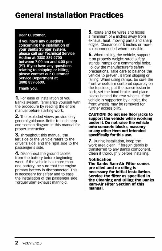
Dear Customer,
If you have any questions concerning the installation of your Banks Stinger system, please call our Technical Service Hotline at (888) 839-2700 between 7:00 am and 4:00 pm (PT). If you have any questions relating to shipping or billing, please contact our Customer Service Department at (888) 839-5600.
Thank you.
1. For ease of installation of you Banks system, familiarize yourself with the procedure by reading the entire manual before starting work.
2. The exploded views provide only general guidance. Refer to each step and section diagram in this manual for proper instruction.
3. Throughout this manual, the left side of the vehicle refers to the driver’s side, and the right side to the passenger’s side.
4. Disconnect the ground cables from the battery before beginning work. If the vehicle has more than one battery, be sure that the engine primary battery is disconnected. This is necessary for safety and to ease the installation of the passenger side TorqueTube® exhaust manifold.
5. Route and tie wires and hoses a minimum of 6 inches away from exhaust heat, moving parts and sharp edges. Clearance of 8 inches or more is recommended where possible.
6. When raising the vehicle, support it on properly weight-rated safety stands, ramps or a commercial hoist. Follow the manufacturer’s safety precautions. Take care to balance the vehicle to prevent it from slipping or falling. When using ramps, be sure the front wheels are centered squarely on the topsides; put the transmission in park; set the hand brake; and place blocks behind the rear wheels. If the vehicle is supported by a hoist, the front wheels may be removed for further accessibility.
CAUTION! Do not use floor jacks to support the vehicle while working under it. Do not raise the vehicle onto concrete blocks, masonry or any other item not intended specifically for this use.
7. During installation, keep the work area clean. If foreign debris is transferred to any Banks component. Clean it thoroughly before installing.
NotificationThe Banks Ram-Air Filter comes pre-oiled and no oiling is necessary for initial installation. Service the filter as specified in the Cleaning and Oiling the Banks Ram-Air Filter Section of this manual.
General Installation Practices
96377 v.12.0 3
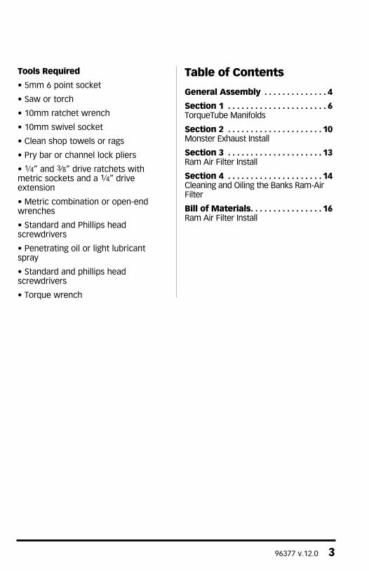
Tools Required
• 5mm 6 point socket
• Saw or torch
• 10mm ratchet wrench
• 10mm swivel socket
• Clean shop towels or rags
• Pry bar or channel lock pliers
• 1⁄4” and 3⁄8” drive ratchets with metric sockets and a 1⁄4” drive extension
• Metric combination or open-end wrenches
• Standard and Phillips head screwdrivers
• Penetrating oil or light lubricant spray
• Standard and phillips head screwdrivers
• Torque wrench
Table of Contents
General Assembly . . . . . . . . . . . . . . 4
Section 1 . . . . . . . . . . . . . . . . . . . . . . 6TorqueTube Manifolds
Section 2 . . . . . . . . . . . . . . . . . . . . . 10Monster Exhaust Install
Section 3 . . . . . . . . . . . . . . . . . . . . . 13Ram Air Filter Install
Section 4 . . . . . . . . . . . . . . . . . . . . . 14Cleaning and Oiling the Banks Ram-Air Filter
Bill of Materials. . . . . . . . . . . . . . . . 16Ram Air Filter Install
4 96377 v.12.0
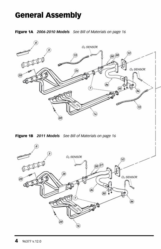
General Assembly
Figure 1A 2006-2010 Models See Bill of Materials on page 16
Figure 1B 2011 Models See Bill of Materials on page 16
96377 v.12.0 5
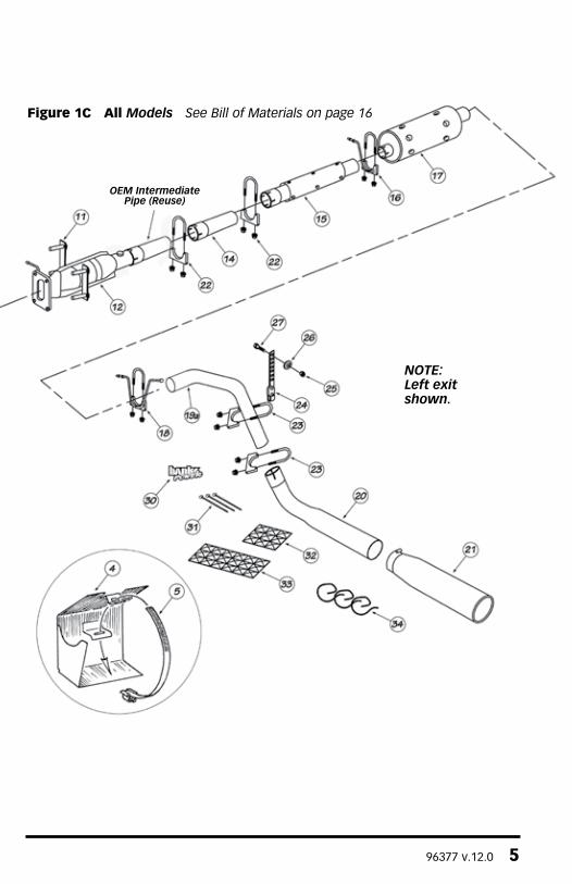
Figure 1C All Models See Bill of Materials on page 16
NOTE: Left exit shown.
OEM Intermediate Pipe (Reuse)
6 96377 v.12.0
Skip to Section 2 for Stinger Install
TORQUETUBE INSTALL
1. With the motorhome safely raised, ground wire(s) disconnected, and precautions in place, remove the factory exhaust system.
2. To provide better access to the manifolds remove the front wheels from the motorhome. If the motorhome is equipped with inner front fender shields, remove them for improved access.
NOTE: Before removing the lug nuts, make sure a capable torque wrench is available to tighten the lug nuts to the manufacturer’s torque specifications
3. The vehicle may have a bolted in crossmember between the leveling jacks at the front of the vehicle. This will need to be removed prior to removing the factory exhaust system and reinstalled after the Banks PowerPack system is place.
WARNING: Do not use the leveling jacks while the cross-member is removed.
4. Locate the oxygen sensors in the exhaust headpipes on each side of the engine, forward of the catalytic converters. Unplug the connectors and unscrew the oxygen sensors, keeping track of the left and right sensors. Be careful not to touch or contaminate the sensor.
5. Remove the factory hardware on the front 2-bolt headpipe flanges.
6. Disconnect the four (4) bolt flange at the front of the catalytic converter. Remove the factory Y-pipe from the vehicle. Retain the factory hardware for reassembly.
NOTE: Whenever possible, it is recommended that the catalytic converters be inspected. Restricted or damaged catalytic converters can
impede performance of your Banks PowerPack.
7. Pull out the dipstick and remove the small bolt that attaches the oil dipstick tube to the cylinder head. At the front of the vehicle, behind the front engine cover, remove the 2 screws that retain the dipstick tube to the radiator support. Near the exhaust manifold, pull the dipstick tube up out of the engine block. Check to see if there is an O-ring on the tube. If not, the O-ring may be stuck inside the hole in the engine block. This O-ring should be retrieved if necessary and placed back onto the tube before reinstalling it. Accessing the dipstick may be easier from the interior engine cover (doghouse).
8. To remove the exhaust manifolds, use a wrench or socket to back the nuts away from the manifolds at least one turn, then use a 5mm 6 point socket to remove each stud from the head. As an alternate method, take the nuts off the studs, and then remove the studs.
9. After the manifolds have been removed from the vehicle, remove any remaining studs from the heads. The studs must be removed from the heads in order to install the Banks TorqueTubes.
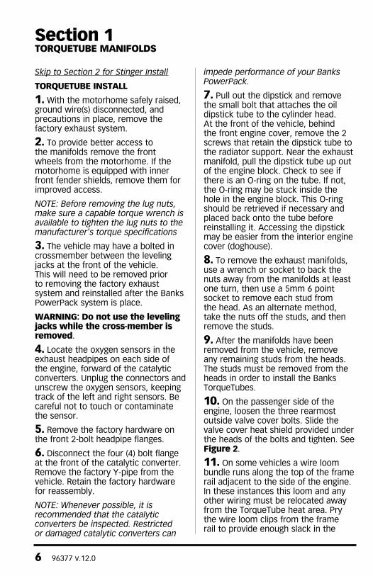
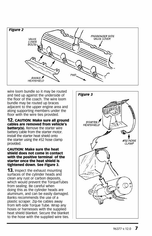
10. On the passenger side of the engine, loosen the three rearmost outside valve cover bolts. Slide the valve cover heat shield provided under the heads of the bolts and tighten. See Figure 2.
11. On some vehicles a wire loom bundle runs along the top of the frame rail adjacent to the side of the engine. In these instances this loom and any other wiring must be relocated away from the TorqueTube heat area. Pry the wire loom clips from the frame rail to provide enough slack in the
Section 1TORQUETUBE MANIFOLDS
96377 v.12.0 7
wire loom bundle so it may be routed and tied up against the underside of the floor of the coach. The wire loom bundle may be routed up braces adjacent to the upper engine area and along supporting members under the floor with the wire ties provided.
12. CAUTION: Make sure all ground cables are removed from vehicle’s battery(s). Remove the starter wire battery cable from the starter motor.Install the starter heat shield onto the starter using the #52 hose clamp provided.
CAUTION: Make sure the heat shield does not come in contact with the positive terminal of the starter once the heat shield is tightened down. See Figure 3.
13. Inspect the exhaust mounting surfaces of the cylinder heads and clean any rust or carbon deposits, which would prevent the TorqueTubes from sealing. Be careful when doing this as the cylinder heads are aluminum, and can be easily damaged. Banks recommends the use of a plastic scraper. Zip-tie cables away from left-side Torque Tube. Wrap any hoses or harnesses with the supplied heat shield blanket. Secure the blanket to the hose with the supplied wire ties.
Figure 3
Figure 2
8 96377 v.12.0
14. Place a small amount of anti-seize on the threads of each of the supplied TorqueTube bolts. Use the new gaskets provided when installing Banks TorqueTubes. The exhaust ports are off-centered so be sure The gaskets are rotated properly.
15. Lift the Banks TorqueTubes and gasket into place and install one or two bolts to hold them in position. Install the remaining bolts into the heads and tighten. Torque the 8mm head bolts to 20 ft-lbs.
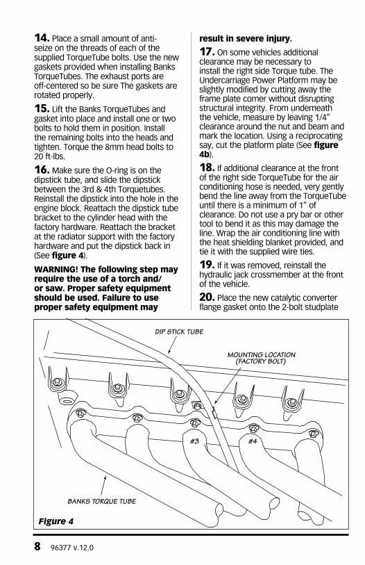
16. Make sure the O-ring is on the dipstick tube, and slide the dipstick between the 3rd & 4th Torquetubes. Reinstall the dipstick into the hole in the engine block. Reattach the dipstick tube bracket to the cylinder head with the factory hardware. Reattach the bracket at the radiator support with the factory hardware and put the dipstick back in (See figure 4).
WARNING! The following step may require the use of a torch and/or saw. Proper safety equipment should be used. Failure to use proper safety equipment may
result in severe injury.
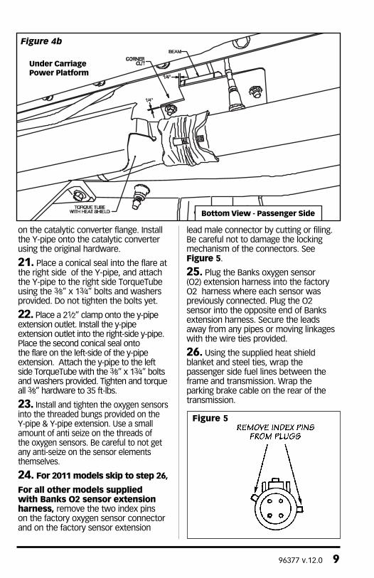
17. On some vehicles additional clearance may be necessary to install the right side Torque tube. The Undercarriage Power Platform may be slightly modified by cutting away the frame plate corner without disrupting structural integrity. From underneath the vehicle, measure by leaving 1/4” clearance around the nut and beam and mark the location. Using a reciprocating say, cut the platform plate (See figure 4b).
18. If additional clearance at the front of the right side TorqueTube for the air conditioning hose is needed, very gently bend the line away from the TorqueTube until there is a minimum of 1” of clearance. Do not use a pry bar or other tool to bend it as this may damage the line. Wrap the air conditioning line with the heat shielding blanket provided, and tie it with the supplied wire ties.
19. If it was removed, reinstall the hydraulic jack crossmember at the front of the vehicle.
20. Place the new catalytic converter flange gasket onto the 2-bolt studplate
DIP STICK TUBE
BANKS TORQUE TUBE
#3 #4
MOUNTING LOCATION(FACTORY BOLT)
Figure 4
96377 v.12.0 9
on the catalytic converter flange. Install the Y-pipe onto the catalytic converter using the original hardware.
21. Place a conical seal into the flare at the right side of the Y-pipe, and attach the Y-pipe to the right side TorqueTube using the 3⁄8” x 13⁄4” bolts and washers provided. Do not tighten the bolts yet.
22. Place a 21⁄2” clamp onto the y-pipe extension outlet. Install the y-pipe extension outlet into the right-side y-pipe. Place the second conical seal onto the flare on the left-side of the y-pipe extension. Attach the y-pipe to the left side TorqueTube with the 3⁄8” x 13⁄4” bolts and washers provided. Tighten and torque all 3⁄8” hardware to 35 ft-lbs.
23. Install and tighten the oxygen sensors into the threaded bungs provided on the Y-pipe & Y-pipe extension. Use a small amount of anti seize on the threads of the oxygen sensors. Be careful to not get any anti-seize on the sensor elements themselves.
24. For 2011 models skip to step 26,
For all other models supplied with Banks O2 sensor extension harness, remove the two index pins on the factory oxygen sensor connector and on the factory sensor extension
lead male connector by cutting or filing. Be careful not to damage the locking mechanism of the connectors. See Figure 5.
25. Plug the Banks oxygen sensor (O2) extension harness into the factory O2 harness where each sensor was previously connected. Plug the O2 sensor into the opposite end of Banks extension harness. Secure the leads away from any pipes or moving linkages with the wire ties provided.
26. Using the supplied heat shield blanket and steel ties, wrap the passenger side fuel lines between the frame and transmission. Wrap the parking brake cable on the rear of the transmission.
Under CarriagePower Platform
Bottom View - Passenger Side
Figure 4b
Figure 5
10 96377 v.12.0
1. Disconnect the negative (ground) cable from the battery (if there is more than one battery, disconnect both negative cables). Secure the cable so it cannot accidentally come in contact with the post.
2. Raise the vehicle and support it securely with properly weight-rated safety stands, ramps or a commercial hoist. Take care to balance the vehicle to prevent it from slipping or falling. When using ramps, be sure the wheels are centered squarely on the topsides. Place the transmission in park (automatic) or reverse (manual), set the parking brake and securely block the wheels that are on the ground. CAUTION: DO NOT WORK UNDER ANY VEHICLE SUPPORTED ONLY BY A JACK. SEVERE INJURY MAY RESULT.
WARNING! The following step may require the use of a torch and/ or saw. Proper safety equipment should be used. Failure to use proper safety equipment may result in severe injury.
3. Begin removing the factory exhaust starting at the muffler. Remove the muffler and tailpipe assembly by removing the clamps or cutting the through the pipe near the joints. Remove tailpipe hanger pin from the rubber hanger.
NOTE, to remove the factory exhaust, an oxy-acetylene torch can be used to heat the factory joints to allow the crimped pipes to separate.
4. Remove muffler’s dual rear hanger pins and single front hanger from the rubber hangers. Remove the tailpipe and muffler.
5. Slide a 3” saddle clamp over the inlet of the Banks intermediate pipe (smaller pipe). Install the Banks intermediate pipe and clamp over the factory intermediate pipe outlet. If no
factory intermediate pipe is installed, align the Banks intermediate pipe notch with the catalytic converter pin. Snug the 3” clamp.
NOTE: all clamps should be positioned at the beginning of the slots (on the 1⁄2 circle punch) and evenly tightened.
6. Install a 3” saddle clamp onto the inlet of the Banks heat-shielded rear intermediate pipe. Install the Banks rear intermediate pipe onto the front intermediate pipe outlet. Snug the 3” clamp.
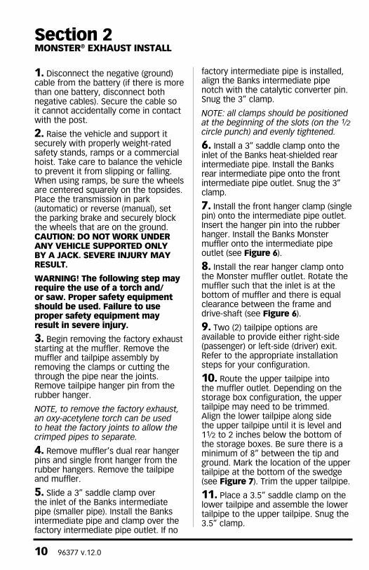
7. Install the front hanger clamp (single pin) onto the intermediate pipe outlet. Insert the hanger pin into the rubber hanger. Install the Banks Monster muffler onto the intermediate pipe outlet (see Figure 6).
8. Install the rear hanger clamp onto the Monster muffler outlet. Rotate the muffler such that the inlet is at the bottom of muffler and there is equal clearance between the frame and drive-shaft (see Figure 6).
9. Two (2) tailpipe options are available to provide either right-side (passenger) or left-side (driver) exit. Refer to the appropriate installation steps for your configuration.
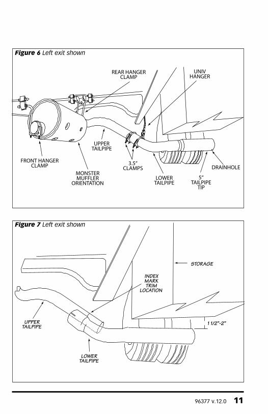
10. Route the upper tailpipe into the muffler outlet. Depending on the storage box configuration, the upper tailpipe may need to be trimmed. Align the lower tailpipe along side the upper tailpipe until it is level and 11⁄2 to 2 inches below the bottom of the storage boxes. Be sure there is a minimum of 8” between the tip and ground. Mark the location of the upper tailpipe at the bottom of the swedge (see Figure 7). Trim the upper tailpipe.
11. Place a 3.5” saddle clamp on the lower tailpipe and assemble the lower tailpipe to the upper tailpipe. Snug the 3.5” clamp.
Section 2MONSTER® EXHAUST INSTALL
96377 v.12.0 11
FRONT HANGERCLAMP
MONSTERMUFFLER
ORIENTATION
UPPERTAILPIPE
3.5“CLAMPS
LOWERTAILPIPE
5“TAILPIPE
TIP
DRAINHOLE
UNIVHANGER
REAR HANGERCLAMP
Figure 6 Left exit shown
UPPERTAILPIPE
LOWERTAILPIPE
INDEXMARKTRIM
LOCATION
STORAGE
1 1/2”-2”
Figure 7 Left exit shown
12 96377 v.12.0
12. Attach a 3.5” clamp to the universal hanger. Put the universal hanger onto the tailpipe. For the universal hanger, find a suitable hole in the frame rail directly over the tailpipe. Using the 3⁄8” hardware, support the universal hanger and tailpipe assembly level to the storage boxes.
13. Install the 5” dual wall tip onto the tailpipe outlet. Adjust the tip such that is a minimum of a 1-inch below the storage boxes. Be sure drainhole is facing down.
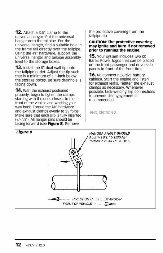
14. With the exhaust postioned properly, begin to tighen the clamps starting with the ones closest to the front of the vehicle and working your way back. Torque the 3⁄8” hardware and exhaust clamps evenly to 35 ft-lbs. Make sure that each slip is fully inserted (+/- 1⁄4”). All hanger pins should be facing forward (see Figure 8). Remove
the protective covering from the tailpipe tip.
CAUTION: The protective covering may ignite and burn if not removed prior to running the engine.
15. Your system includes two (2) Banks Power logos that can be placed on the front passenger and driverside panels in front of the front tires.
16. Re-connect negative battery cable(s). Start the engine and listen for exhaust leaks. Tighten the exhaust clamps as necessary. Whenever possible, tack-welding slip connections to prevent disengagement is recommended.
-END, SECTION 2-
Figure 8
96377 v.12.0 13
1. Locate the engine air filter box by lifting the hood on the front of the motorhome. Remove the cover by releasing the four (4) clips on the sides of the housing and slide the cover toward the front of the motorhome.
2. Remove the old air filter element from the filter housing and replace it with the Banks Ram-Air filter element. Place the Banks filter element in the right orientation and check the filter seal is seating properly around the
housing to ensure no leakage. For proper maintenance and service on the Banks Ram-Air Filter, refer to CLEANING AND OILING THE BANKS RAM-AIR FILTER.
3. Slide the tabs on the cover into the slots on the air filter box. Press the cover down gently and re-attach the four (4) clips on the side to securely clamp the cover.
-END, SECTION 3-
Section 3RAM AIR FILTER INSTALL
14 96377 v.12.0
NotificationThe Banks Ram-Air Filter comes pre-oiled and no oiling is necessary for initial installation.
Use Banks Ram-Air Filter cleaning system (part #90094), available from Gale Banks Engineering to service the Air Filter. Follow the instructions included with the cleaning system to clean and re-oil your Banks Ram-Air Filter.
1. PRE-CLEANING
Tap the element to dislodge any large embedded dirt, then gently brush with a soft bristle brush. NOTE: If complete cleaning is not practical at this time, reoil the element and reinstall in your vehicle.
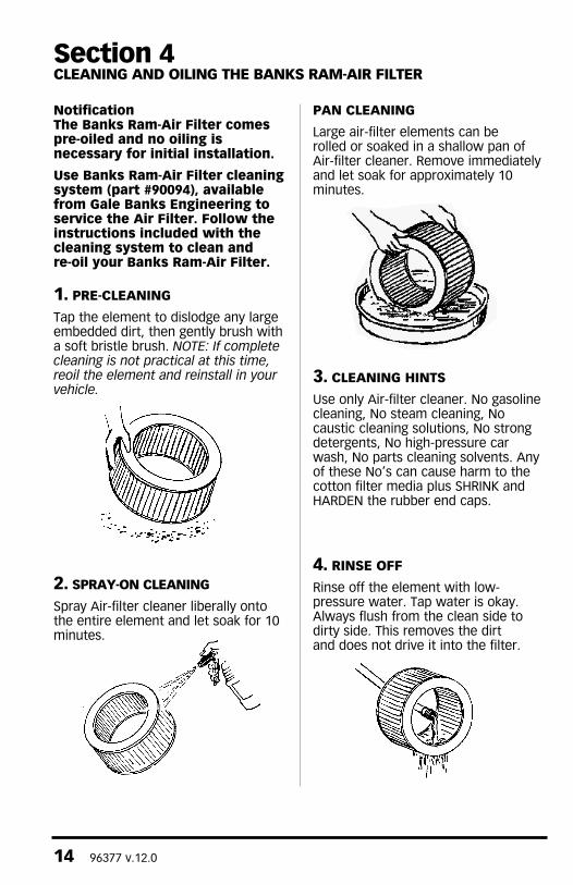
2. SPRAY-ON CLEANING
Spray Air-filter cleaner liberally onto the entire element and let soak for 10 minutes.
PAN CLEANING
Large air-filter elements can be rolled or soaked in a shallow pan of Air-filter cleaner. Remove immediately and let soak for approximately 10 minutes.
3. CLEANING HINTS
Use only Air-filter cleaner. No gasoline cleaning, No steam cleaning, No caustic cleaning solutions, No strong detergents, No high-pressure car wash, No parts cleaning solvents. Any of these No’s can cause harm to the cotton filter media plus SHRINK and HARDEN the rubber end caps.
4. RINSE OFF
Rinse off the element with low-pressure water. Tap water is okay. Always flush from the clean side to dirty side. This removes the dirt and does not drive it into the filter.
Section 4CLEANING AND OILING THE BANKS RAM-AIR FILTER
96377 v.12.0 15
5. DRYING HINTS
Always dry naturally. After rinsing, shake off all excess water and let the element dry naturally. DO NOT USE COMPRESSED AIR – DO NOT USE OPEN FLAME – DO NOT USE HEAT DRYERS!
EXCESS HEAT WILL SHRINK THE COTTON FILTER MEDIA. COMPRESSED AIR WILL BLOW HOLES IN THE ELEMENT.
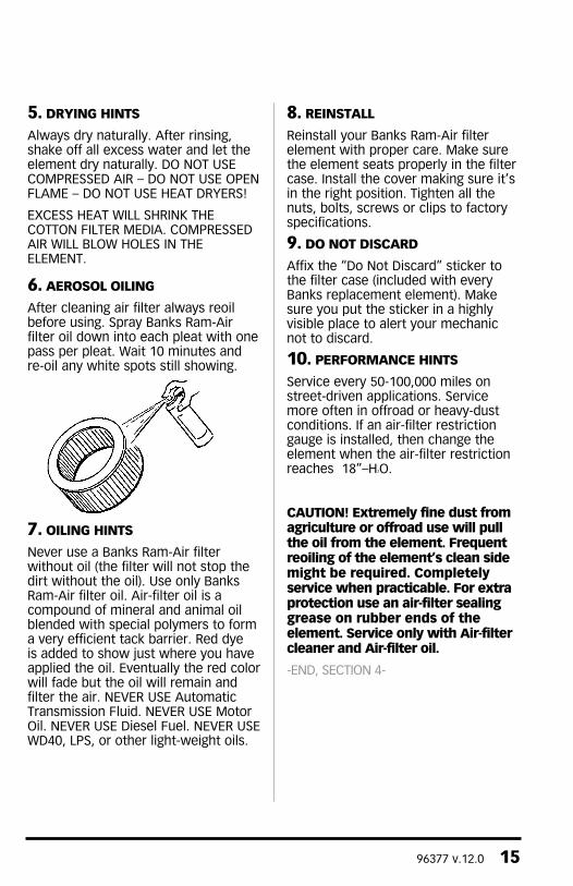
6. AEROSOL OILING
After cleaning air filter always reoil before using. Spray Banks Ram-Air filter oil down into each pleat with one pass per pleat. Wait 10 minutes and re-oil any white spots still showing.
7. OILING HINTS
Never use a Banks Ram-Air filter without oil (the filter will not stop the dirt without the oil). Use only Banks Ram-Air filter oil. Air-filter oil is a compound of mineral and animal oil blended with special polymers to form a very efficient tack barrier. Red dye is added to show just where you have applied the oil. Eventually the red color will fade but the oil will remain and filter the air. NEVER USE Automatic Transmission Fluid. NEVER USE Motor Oil. NEVER USE Diesel Fuel. NEVER USE WD40, LPS, or other light-weight oils.
8. REINSTALL
Reinstall your Banks Ram-Air filter element with proper care. Make sure the element seats properly in the filter case. Install the cover making sure it’s in the right position. Tighten all the nuts, bolts, screws or clips to factory specifications.
9. DO NOT DISCARD
Affix the “Do Not Discard” sticker to the filter case (included with every Banks replacement element). Make sure you put the sticker in a highly visible place to alert your mechanic not to discard.
10. PERFORMANCE HINTS
Service every 50-100,000 miles on street-driven applications. Service more often in offroad or heavy-dust conditions. If an air-filter restriction gauge is installed, then change the element when the air-filter restriction reaches 18”–H2O.
CAUTION! Extremely fine dust from agriculture or offroad use will pull the oil from the element. Frequent reoiling of the element’s clean side might be required. Completely service when practicable. For extra protection use an air-filter sealing grease on rubber ends of the element. Service only with Air-filter cleaner and Air-filter oil.
-END, SECTION 4-
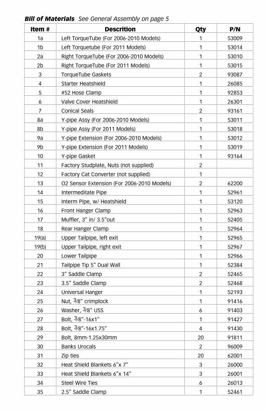
Item # Descrition Qty P/N1a Left TorqueTube (For 2006-2010 Models) 1 53009
1b Left Torquetube (For 2011 Models) 1 53014
2a Right TorqueTube (For 2006-2010 Models) 1 53010
2b Right TorqueTube (For 2011 Models) 1 53015
3 TorqueTube Gaskets 2 93087
4 Starter Heatshield 1 26085
5 #52 Hose Clamp 1 92853
6 Valve Cover Heatshield 1 26301
7 Conical Seals 2 93161
8a Y-pipe Assy (For 2006-2010 Models) 1 53011
8b Y-pipe Assy (For 2011 Models) 1 53018
9a Y-pipe Extension (For 2006-2010 Models) 1 53012
9b Y-pipe Extension (For 2011 Models) 1 53019
10 Y-pipe Gasket 1 93164
11 Factory Studplate, Nuts (not supplied) 2
12 Factory Cat Converter (not supplied) 1
13 O2 Sensor Extension (For 2006-2010 Models) 2 62200
14 Intermeditate Pipe 1 52961
15 Interm Pipe, w/ Heatshield 1 53120
16 Front Hanger Clamp 1 52963
17 Muffler, 3” in/ 3.5”out 1 52405
18 Rear Hanger Clamp 1 52964
19(a) Upper Tailpipe, left exit 1 52965
19(b) Upper Tailpipe, right exit 1 52967
20 Lower Tailpipe 1 52966
21 Tailpipe Tip 5” Dual Wall 1 52384
22 3” Saddle Clamp 2 52465
23 3.5” Saddle Clamp 2 52468
24 Universal Hanger 1 52193
25 Nut, 3⁄8” crimplock 1 91416
26 Washer, 3⁄8” USS 6 91403
27 Bolt, 3⁄8”-16x1” 1 91427
28 Bolt, 3⁄8”-16x1.75” 4 91430
29 Bolt, 8mm-1.25x30mm 20 91811
30 Banks Urocals 2 96009
31 Zip ties 20 62001
32 Heat Shield Blankets 6”x 7” 3 26000
33 Heat Shield Blankets 6”x 14” 3 26001
34 Steel Wire Ties 6 26013
35 2.5” Saddle Clamp 1 52461
Bill of Materials See General Assembly on page 5