Embed Size (px)
Citation preview
OWNER'S MANUAL 2015
200 Duke 2015 COArt. no. 3213118en

DEAR KTM CUSTOMER 1
DEAR KTM CUSTOMER
Congratulations on your decision to purchase a KTM motorcycle. You are now the owner of a state-of-the-art sports motorcycle that willgive you enormous pleasure if you service and maintain it accordingly.
We wish you a lot of enjoyment in riding this vehicle.
Enter the serial numbers of your vehicle below.
Chassis number/type label ( p. 20) Dealer's stamp
Engine number ( p. 20)
Key number ( p. 21)
The Owner's Manual contained the latest information for this model series at the time of going to print. Minor differences due to develop-ments in design cannot be ruled out completely.
All specifications are non-binding. KTM Sportmotorcycle AG specifically reserves the right to modify or delete technical specifications,prices, colors, forms, materials, services, designs, equipment, etc., without prior notice and without specifying reasons, to adapt theseto local conditions, as well as to stop production of a particular model without prior notice. KTM accepts no liability for delivery options,deviations from illustrations and descriptions, as well as misprints and other errors. The models portrayed partly contain special equipmentthat does not belong to the regular scope of supply.
© 2014 KTM-Sportmotorcycle AG, Mattighofen AustriaAll rights reservedReproduction, even in part, as well as copying of all kinds, is permitted only with the express written permission of the copyright owner.
DEAR KTM CUSTOMER 2
ISO 9001(12 100 6061)According to the international quality management standard ISO 9001, KTM uses quality assurance processes that lead tothe maximum possible quality of the products.Issued by: TÜV Management Service
KTM-Sportmotorcycle AG5230 Mattighofen, Austria
TABLE OF CONTENTS 3
TABLE OF CONTENTS
1 MEANS OF REPRESENTATION ........................................ 71.1 Symbols used ...................................................... 71.2 Formats used....................................................... 7
2 SAFETY ADVICE.............................................................. 82.1 Use definition...................................................... 82.2 Safety advice....................................................... 82.3 Degrees of risk and symbols .................................. 92.4 Tampering warning............................................... 92.5 Safe operation ................................................... 102.6 Protective clothing ............................................. 112.7 Work rules......................................................... 112.8 Environment...................................................... 112.9 Owner's Manual ................................................. 12
3 IMPORTANT INFORMATION .......................................... 133.1 Guarantee, warranty ........................................... 133.2 Operating and auxiliary substances ...................... 133.3 Spare parts, accessories ..................................... 133.4 Service ............................................................. 133.5 Figures ............................................................. 143.6 Customer service................................................ 14
4 VIEW OF VEHICLE ........................................................ 164.1 View of vehicle, front left (example) ..................... 164.2 View of vehicle, rear right (example) .................... 18
5 SERIAL NUMBERS ....................................................... 205.1 Chassis number/type label .................................. 205.2 Engine number .................................................. 205.3 Key number....................................................... 21
6 CONTROLS................................................................... 226.1 Clutch lever....................................................... 22
6.2 Hand brake lever................................................ 226.3 Throttle grip ...................................................... 236.4 Horn button....................................................... 236.5 Light switch ...................................................... 246.6 High beam flasher button ................................... 246.7 Turn signal switch.............................................. 256.8 Emergency OFF switch ....................................... 256.9 Electric starter button......................................... 266.10 Ignition/steering lock.......................................... 266.11 Combination instrument ..................................... 276.11.1 Overview ....................................................... 276.11.2 Activation and test ......................................... 286.11.3 Warning notes ............................................... 296.11.4 Function buttons ........................................... 326.11.5 Indicator lamps ............................................. 336.11.6 Display ......................................................... 346.11.7 Filling level display in fuel tank....................... 356.11.8 TRIP F display............................................... 366.11.9 Coolant temperature indicator ......................... 376.11.10 Info display ................................................... 386.11.11 Riding time/average speed menu ..................... 396.11.12 Average speed/average fuel consumption 1
menu............................................................ 396.11.13 Average fuel consumption 1/average fuel
consumption 2 menu ..................................... 406.11.14 Average fuel consumption 2/service menu ........ 416.11.15 Service/range menu........................................ 426.11.16 Range/riding time menu ................................. 436.11.17 Total distance menu ODO ............................... 44
TABLE OF CONTENTS 4
6.11.18 Distance menu 1 TRIP 1 ................................ 446.11.19 Distance menu 2 TRIP 2 ................................ 456.11.20 Setting kilometers or miles ............................. 456.11.21 Setting the time............................................. 466.11.22 Adjusting the shift speed RPM 1..................... 476.11.23 Adjusting the shift speed RPM 2..................... 476.12 Opening the filler cap......................................... 486.13 Closing the filler cap .......................................... 506.14 Seat lock........................................................... 506.15 Tool set............................................................. 516.16 Grab handles ..................................................... 516.17 Passenger footrests ............................................ 526.18 Shift lever ......................................................... 526.19 Foot brake lever ................................................. 536.20 Side stand......................................................... 54
7 PREPARING FOR USE................................................... 557.1 Advice on first use ............................................. 557.2 Running in the engine ........................................ 567.3 Loading the vehicle ............................................ 57
8 RIDING INSTRUCTIONS................................................ 598.1 Checks and maintenance when preparing for
use ................................................................... 598.2 Starting............................................................. 608.3 Starting off........................................................ 618.4 Shifting, riding .................................................. 628.5 Applying the brakes............................................ 648.6 Stopping, parking............................................... 668.7 Transport .......................................................... 678.8 Refueling .......................................................... 68
9 SERVICE SCHEDULE .................................................... 709.1 Service schedule................................................ 70
10 TUNING THE CHASSIS ................................................. 7210.1 Adjusting the spring preload of the shock
absorberx....................................................... 7210.2 Adjusting the shift lever...................................... 73
11 SERVICE WORK ON THE CHASSIS................................. 7411.1 Raising the motorcycle with the rear wheel
stand ................................................................ 7411.2 Taking the motorcycle off of the rear wheel
stand ................................................................ 7411.3 Raising the motorcycle with the front wheel
stand ................................................................ 7511.4 Taking the motorcycle off of the front wheel
stand ................................................................ 7611.5 Removing the passenger seat .............................. 7711.6 Mounting the passenger seat............................... 7811.7 Removing the seat ............................................. 7811.8 Mounting the seat .............................................. 7911.9 Checking for chain dirt accumulation................... 8011.10 Cleaning the chain ............................................. 8011.11 Checking the chain tension ................................. 8111.12 Adjusting the chain tension................................. 8311.13 Checking the chain, rear sprocket, and engine
sprocket............................................................ 8511.14 Removing the front spoiler .................................. 8911.15 Fitting front spoiler ............................................ 90
12 BRAKE SYSTEM ........................................................... 9112.1 Checking the brake discs .................................... 9112.2 Checking the brake fluid level of the front brake ... 91
TABLE OF CONTENTS 5
12.3 Adding front brake fluidx................................. 9212.4 Checking the front brake linings .......................... 9412.5 Checking the free travel of foot brake lever ........... 9512.6 Adjusting the free travel of the foot brake
leverx ............................................................ 9612.7 Checking the rear brake fluid level....................... 9712.8 Adding rear brake fluidx .................................. 9712.9 Checking the rear brake linings ........................... 99
13 WHEELS, TIRES ......................................................... 10113.1 Removing the front wheelx ............................ 10113.2 Installing the front wheelx ............................. 10213.3 Removing the rear wheelx.............................. 10413.4 Installing the rear wheelx .............................. 10513.5 Checking the rear hub rubber dampersx.......... 10613.6 Checking the tire condition ............................... 10813.7 Checking the tire air pressure............................ 109
14 ELECTRICAL SYSTEM ................................................. 11114.1 Removing the batteryx .................................. 11114.2 Installing the batteryx ................................... 11214.3 Recharging the batteryx ................................ 11314.4 Changing the fuses of individual power
consumers....................................................... 11614.5 Changing the headlight bulb ............................. 11814.6 Changing the parking light bulb......................... 12014.7 Checking the headlight setting .......................... 12414.8 Adjusting the headlight range............................ 125
15 COOLING SYSTEM...................................................... 12815.1 Cooling system ................................................ 12815.2 Checking the antifreeze and coolant level ........... 129
15.3 Checking the coolant level ................................ 13115.4 Draining the coolantx .................................... 13315.5 Filling/bleeding the cooling systemx ............... 134
16 TUNING THE ENGINE................................................. 13616.1 Checking the play in the throttle cable ............... 13616.2 Adjusting the play in the throttle cablex.......... 13716.3 Checking the clutch lever play........................... 13716.4 Adjusting the clutch cable playx .................... 138
17 SERVICE WORK ON THE ENGINE ................................ 13917.1 Checking the engine oil level............................. 13917.2 Changing the engine oil and oil filter, cleaning
the oil screenx.............................................. 13917.3 Adding engine oil ............................................. 142
18 CLEANING, CARE ....................................................... 14418.1 Cleaning the motorcycle ................................... 14418.2 Checks and maintenance steps for winter
operation......................................................... 14619 STORAGE................................................................... 148
19.1 Storage ........................................................... 14819.2 Preparing for use after storage........................... 149
20 TROUBLESHOOTING .................................................. 15021 TECHNICAL DATA....................................................... 153
21.1 Engine ............................................................ 15321.2 Engine tightening torques ................................. 15421.3 Capacities ....................................................... 15621.3.1 Engine oil ................................................... 15621.3.2 Coolant ....................................................... 15621.3.3 Fuel ........................................................... 15721.4 Chassis ........................................................... 157
TABLE OF CONTENTS 6
21.5 Electrical system.............................................. 15821.6 Tires ............................................................... 15921.7 Fork................................................................ 15921.8 Shock absorber ................................................ 15921.9 Chassis tightening torques ................................ 160
22 SUBSTANCES ............................................................ 16423 AUXILIARY SUBSTANCES ........................................... 16724 STANDARDS .............................................................. 169INDEX ............................................................................... 170
1 MEANS OF REPRESENTATION 7
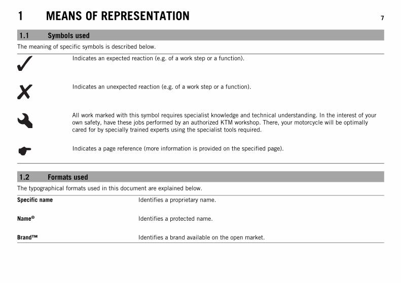
1.1 Symbols usedThe meaning of specific symbols is described below.
Indicates an expected reaction (e.g. of a work step or a function).
Indicates an unexpected reaction (e.g. of a work step or a function).
All work marked with this symbol requires specialist knowledge and technical understanding. In the interest of yourown safety, have these jobs performed by an authorized KTM workshop. There, your motorcycle will be optimallycared for by specially trained experts using the specialist tools required.
Indicates a page reference (more information is provided on the specified page).
1.2 Formats usedThe typographical formats used in this document are explained below.
Specific name Identifies a proprietary name.
Name® Identifies a protected name.
Brand™ Identifies a brand available on the open market.
2 SAFETY ADVICE 8
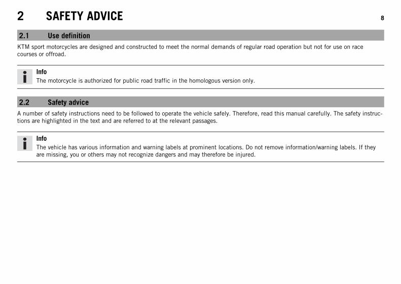
2.1 Use definitionKTM sport motorcycles are designed and constructed to meet the normal demands of regular road operation but not for use on racecourses or offroad.
InfoThe motorcycle is authorized for public road traffic in the homologous version only.
2.2 Safety adviceA number of safety instructions need to be followed to operate the vehicle safely. Therefore, read this manual carefully. The safety instruc-tions are highlighted in the text and are referred to at the relevant passages.
InfoThe vehicle has various information and warning labels at prominent locations. Do not remove information/warning labels. If theyare missing, you or others may not recognize dangers and may therefore be injured.
2 SAFETY ADVICE 9
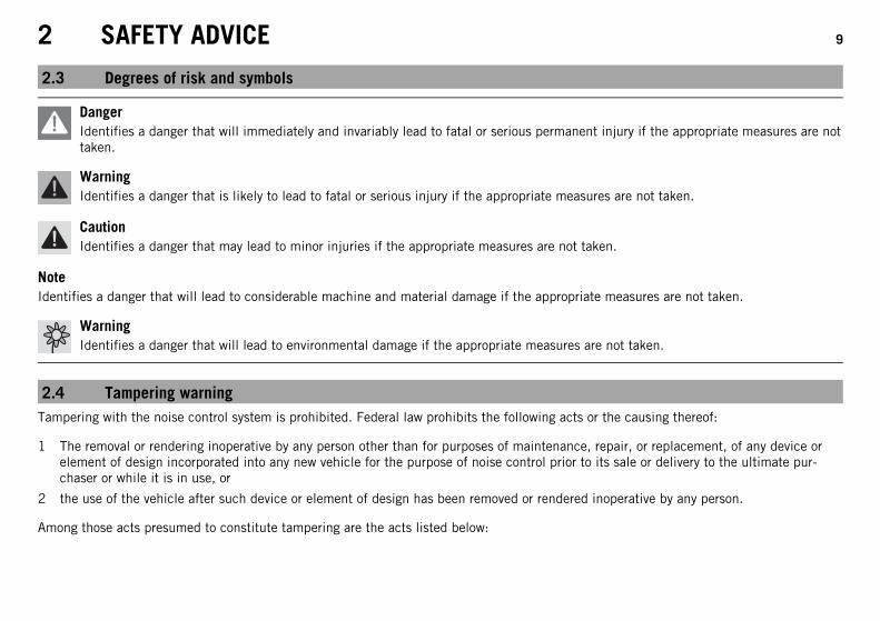
2.3 Degrees of risk and symbols
DangerIdentifies a danger that will immediately and invariably lead to fatal or serious permanent injury if the appropriate measures are nottaken.
WarningIdentifies a danger that is likely to lead to fatal or serious injury if the appropriate measures are not taken.
CautionIdentifies a danger that may lead to minor injuries if the appropriate measures are not taken.
NoteIdentifies a danger that will lead to considerable machine and material damage if the appropriate measures are not taken.
WarningIdentifies a danger that will lead to environmental damage if the appropriate measures are not taken.
2.4 Tampering warningTampering with the noise control system is prohibited. Federal law prohibits the following acts or the causing thereof:
1 The removal or rendering inoperative by any person other than for purposes of maintenance, repair, or replacement, of any device orelement of design incorporated into any new vehicle for the purpose of noise control prior to its sale or delivery to the ultimate pur-chaser or while it is in use, or
2 the use of the vehicle after such device or element of design has been removed or rendered inoperative by any person.
Among those acts presumed to constitute tampering are the acts listed below:
2 SAFETY ADVICE 10
1 Removal or puncturing of the main silencer, baffles, header pipes or any other components which conduct exhaust gases.
2 Removal or puncturing of parts of the intake system.
3 Lack of proper maintenance.
4 Replacing moving part of the vehicle, or parts of the exhaust or intake system, with parts other than those specified by the manufac-turer.
2.5 Safe operation
DangerDanger of accidents Danger arising from the rider's judgement being impaired.
– Do not operate the vehicle while under the influence of alcohol, drugs and certain medications or physically or mentallyimpaired.
DangerDanger of poisoning Exhaust gases are toxic and inhaling them may result in unconsciousness and/or death.
– When running the engine, always make sure there is sufficient ventilation, and do not start or run the engine in an enclosedspace without an effective exhaust extraction system.
WarningDanger of burns Some vehicle components become very hot when the vehicle is operated.
– Do not touch hot components such as exhaust system, radiator, engine, shock absorber, and the brake system. Allow thesecomponents to cool down before starting work on them.
Only operate the vehicle when it is in perfect technical condition, in accordance with its intended use, and in a safe and environmentallycompatible manner.An appropriate driver's license is needed to ride the vehicle on public roads.Have malfunctions that impair safety promptly eliminated by an authorized KTM workshop.Adhere to the information and warning labels on the vehicle.
2 SAFETY ADVICE 11
2.6 Protective clothing
WarningRisk of injury Missing or poor protective clothing presents an increased safety risk.
– Wear protective clothing (helmet, boots, gloves, pants and jacket with protectors) every time you ride the vehicle. Always wearprotective clothing that is in good condition and meets the legal requirements.
In the interest of your own safety, KTM recommends that you only operate the vehicle while wearing protective clothing.
2.7 Work rulesSpecial tools are necessary for certain tasks. The tools are not contained in the vehicle but can be ordered under the number in parenthe-ses. E.g.: bearing puller (15112017000)During assembly, non-reusable parts (e.g. self-locking screws and nuts, seals and seal rings, O-rings, pins, lock washers) must be replacedby new parts.In some instances, a thread locker (e.g. Loctite®) is required. The manufacturer instructions for use must be followed.After disassembly, clean the parts that are to be reused and check them for damage and wear. Change damaged or worn parts.After you complete the repair or service work, check the operating safety of the vehicle.
2.8 EnvironmentIf you use your motorcycle responsibly, you can ensure that problems and conflicts do not occur. To protect the future of the motorcyclesport, make sure that you use your motorcycle legally, display environmental consciousness, and respect the rights of others.When disposing of used oil, other operating and auxiliary fluids, and used components, comply with the laws and regulations of therespective country.Because motorcycles are not subject to the EU regulations governing the disposal of used vehicles, there are no legal regulations that per-tain to the disposal of an end-of-life motorcycle. Your authorized KTM dealer will be glad to advise you.
2 SAFETY ADVICE 12
2.9 Owner's ManualIt is important that you read this Owner's Manual carefully and completely before making your first trip. The Owner's Manual contains use-ful information and many tips on how to operate, handle, and maintain your motorcycle. Only then will you find out how to customize thevehicle ideally for your own use and how you can protect yourself from injury.Keep the Owner's Manual in an accessible place to enable you to refer to it as needed.If you would like to know more about the vehicle or have questions on the material you read, please contact an authorized KTM dealer.The Owner's Manual is an important component of the vehicle and should be handed over to the new owner if the vehicle is sold.
3 IMPORTANT INFORMATION 13
3.1 Guarantee, warrantyThe work prescribed in the service schedule must be carried out by an authorized KTM workshop only and confirmed in the customer'sService & Warranty Booklet and in the KTM dealer.net; otherwise, all warranty claims will be void. No warranty claims can be consideredfor damage resulting from manipulations and/or alterations to the vehicle.Additional information on the guarantee or warranty and the procedures involved can be found in the Service & Warranty Booklet.
3.2 Operating and auxiliary substances
WarningEnvironmental hazard Improper handling of fuel is a danger to the environment.
– Do not allow fuel to get into the ground water, the ground, or the sewage system.
Use operating and auxiliary substances (such as fuel and lubricants) as specified in the Owner's Manual.
3.3 Spare parts, accessoriesFor your own safety, only use spare parts and accessory products that are approved and/or recommended by KTM and have them installedby an authorized KTM workshop. KTM accepts no liability for other products and any resulting damage or loss.Certain spare parts and accessory products are specified in parentheses in the descriptions. Your authorized KTM dealer will be glad toadvise you.
The current KTM PowerParts for your vehicle can be found on the KTM website.International KTM Website: http://www.ktm.com
3.4 ServiceA prerequisite for perfect operation and prevention of premature wear is that the service, care, and tuning work on the engine and chassisis properly carried out as described in the Owner's Manual. Incorrect adjustment and tuning of the engine and chassis can lead to damageand breakage of components.
3 IMPORTANT INFORMATION 14
Use of the vehicle under difficult conditions, such in rain, high heat or with a heavy load, can lead to considerably more rapid wear ofcomponents such as the drive train, brake system, or suspension components. For this reason, it may be necessary to inspect or replaceparts before the next scheduled service.It is imperative that you adhere to the stipulated run-in times and service intervals. If you observe these exactly, you will ensure a muchlonger service life for your motorcycle.
3.5 FiguresThe figures contained in the manual may depict special equipment.In the interest of clarity, some components may be shown disassembled or may not be shown at all. It is not always necessary to disassem-ble the component to perform the activity in question. Please follow the instructions in the text.
3.6 Customer serviceYour authorized KTM dealer will be happy to answer any questions you may have on your vehicle and KTM.
A list of authorized KTM dealers can be found on the KTM website.International KTM Website: http://www.ktm.com

15
4 VIEW OF VEHICLE 16
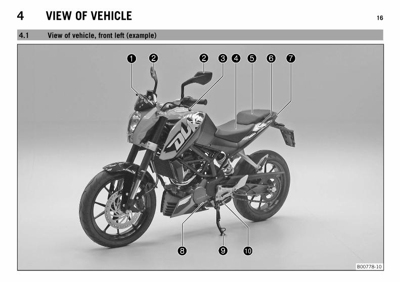
4.1 View of vehicle, front left (example)
B00778-10
4 VIEW OF VEHICLE 17
1 Function buttons ( p. 32)
1 Indicator lamps ( p. 33)
2 Rear mirror
3 Clutch lever ( p. 22)
4 Seat
5 Passenger seat
6 Seat lock ( p. 50)
7 Grab handles ( p. 51)
8 Engine number ( p. 20)
9 Side stand ( p. 54)
10 Shift lever ( p. 52)
4 VIEW OF VEHICLE 18
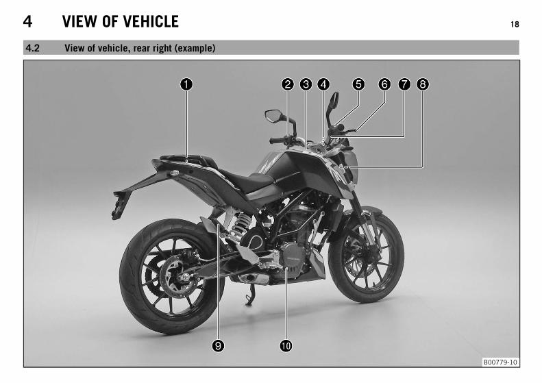
4.2 View of vehicle, rear right (example)
B00779-10
4 VIEW OF VEHICLE 19
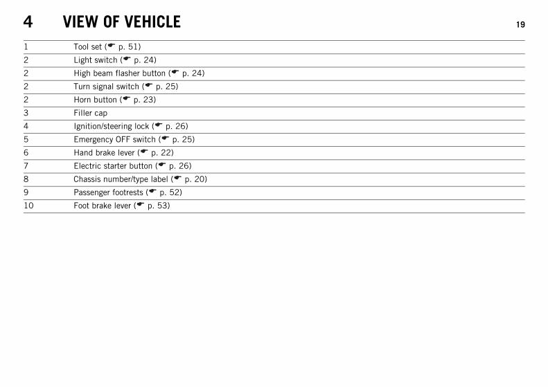
1 Tool set ( p. 51)
2 Light switch ( p. 24)
2 High beam flasher button ( p. 24)
2 Turn signal switch ( p. 25)
2 Horn button ( p. 23)
3 Filler cap
4 Ignition/steering lock ( p. 26)
5 Emergency OFF switch ( p. 25)
6 Hand brake lever ( p. 22)
7 Electric starter button ( p. 26)
8 Chassis number/type label ( p. 20)
9 Passenger footrests ( p. 52)
10 Foot brake lever ( p. 53)
5 SERIAL NUMBERS 20
5.1 Chassis number/type label
B00699-10
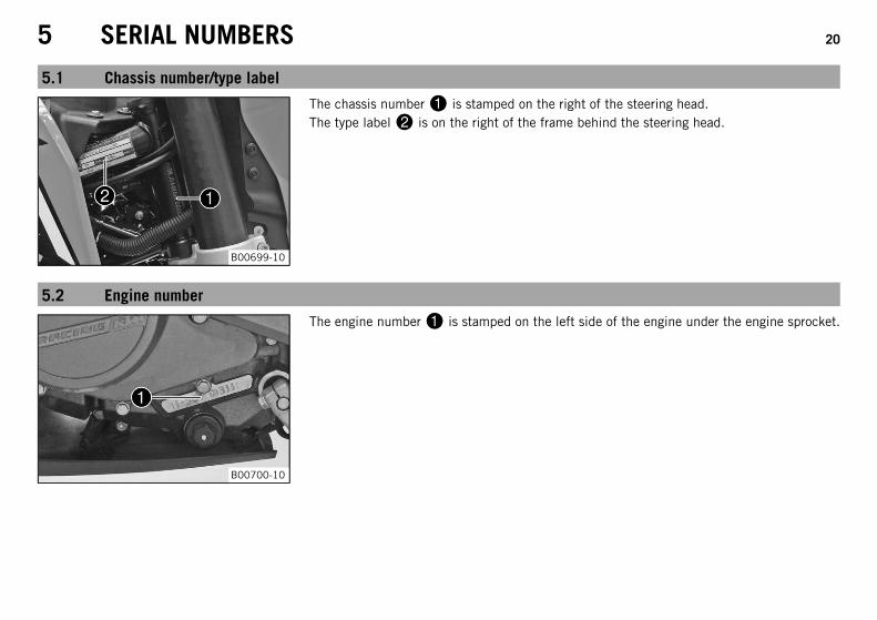
The chassis number is stamped on the right of the steering head.The type label is on the right of the frame behind the steering head.
5.2 Engine number
B00700-10
The engine number is stamped on the left side of the engine under the engine sprocket.
5 SERIAL NUMBERS 21
5.3 Key number
B00755-10
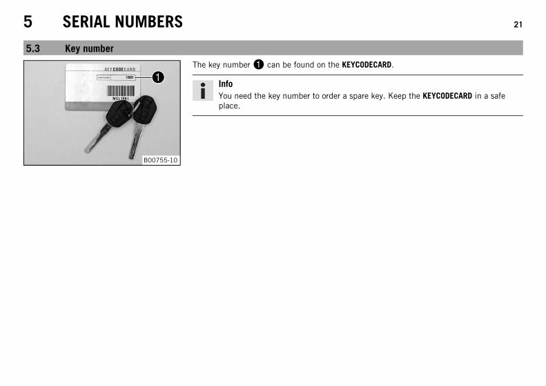
The key number can be found on the KEYCODECARD.
InfoYou need the key number to order a spare key. Keep the KEYCODECARD in a safeplace.
6 CONTROLS 22
6.1 Clutch lever
M00001-10
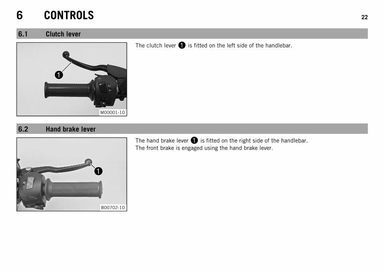
The clutch lever is fitted on the left side of the handlebar.
6.2 Hand brake lever
B00702-10
The hand brake lever is fitted on the right side of the handlebar.The front brake is engaged using the hand brake lever.
6 CONTROLS 23
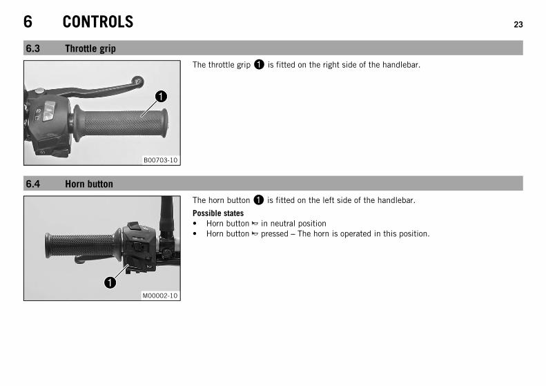
6.3 Throttle grip
B00703-10
The throttle grip is fitted on the right side of the handlebar.
6.4 Horn button
M00002-10
The horn button is fitted on the left side of the handlebar.
Possible states• Horn button in neutral position• Horn button pressed – The horn is operated in this position.
6 CONTROLS 24
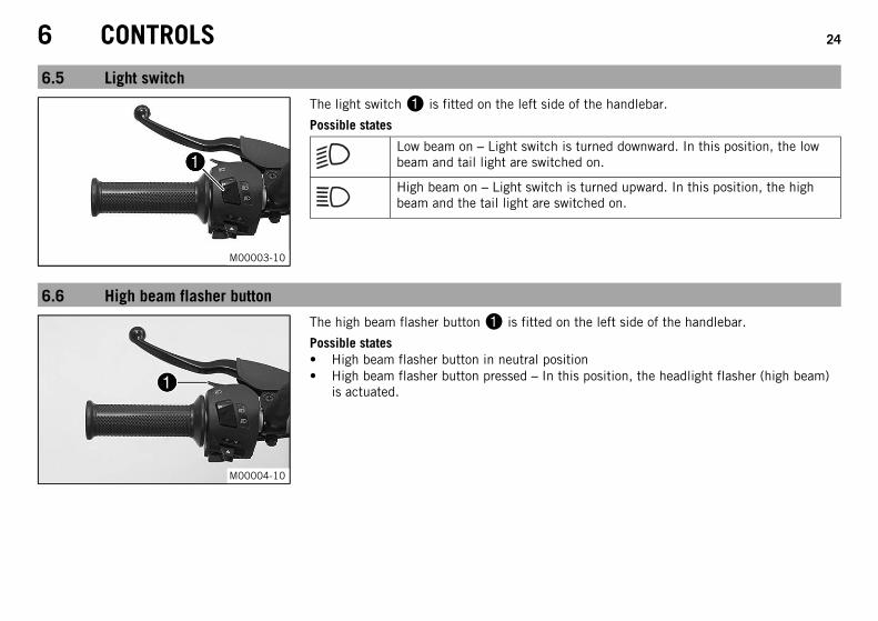
6.5 Light switch
M00003-10
The light switch is fitted on the left side of the handlebar.
Possible states
Low beam on – Light switch is turned downward. In this position, the lowbeam and tail light are switched on.
High beam on – Light switch is turned upward. In this position, the highbeam and the tail light are switched on.
6.6 High beam flasher button
M00004-10
The high beam flasher button is fitted on the left side of the handlebar.
Possible states• High beam flasher button in neutral position• High beam flasher button pressed – In this position, the headlight flasher (high beam)
is actuated.
6 CONTROLS 25
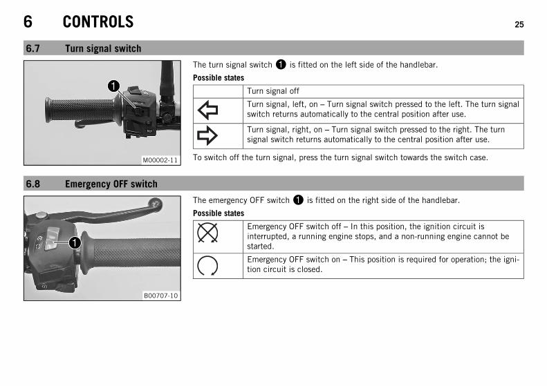
6.7 Turn signal switch
M00002-11
The turn signal switch is fitted on the left side of the handlebar.
Possible states
Turn signal off
Turn signal, left, on – Turn signal switch pressed to the left. The turn signalswitch returns automatically to the central position after use.
Turn signal, right, on – Turn signal switch pressed to the right. The turnsignal switch returns automatically to the central position after use.
To switch off the turn signal, press the turn signal switch towards the switch case.
6.8 Emergency OFF switch
B00707-10
The emergency OFF switch is fitted on the right side of the handlebar.
Possible states
Emergency OFF switch off – In this position, the ignition circuit isinterrupted, a running engine stops, and a non-running engine cannot bestarted.
Emergency OFF switch on – This position is required for operation; the igni-tion circuit is closed.
6 CONTROLS 26
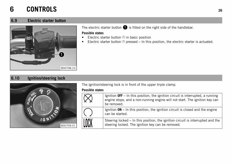
6.9 Electric starter button
B00708-10
The electric starter button is fitted on the right side of the handlebar.
Possible states• Electric starter button in basic position• Electric starter button pressed – In this position, the electric starter is actuated.
6.10 Ignition/steering lock
B00709-01
The ignition/steering lock is in front of the upper triple clamp.
Possible states
Ignition OFF – In this position, the ignition circuit is interrupted, a runningengine stops, and a non-running engine will not start. The ignition key canbe removed.
Ignition ON – In this position, the ignition circuit is closed and the enginecan be started.
Steering locked – In this position, the ignition circuit is interrupted and thesteering locked. The ignition key can be removed.
6 CONTROLS 27
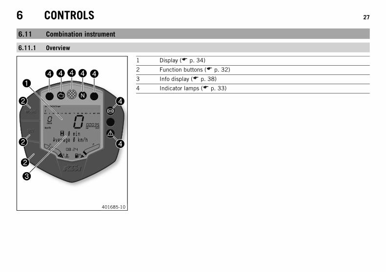
6.11 Combination instrument
6.11.1 Overview
401685-10
1 Display ( p. 34)
2 Function buttons ( p. 32)
3 Info display ( p. 38)
4 Indicator lamps ( p. 33)
6 CONTROLS 28
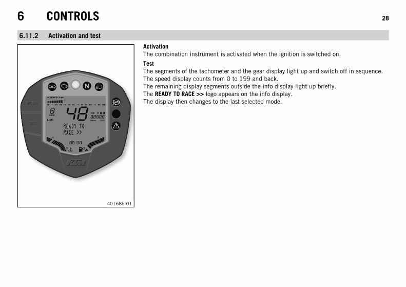
6.11.2 Activation and test
401686-01
ActivationThe combination instrument is activated when the ignition is switched on.
TestThe segments of the tachometer and the gear display light up and switch off in sequence.The speed display counts from 0 to 199 and back.The remaining display segments outside the info display light up briefly.The READY TO RACE >> logo appears on the info display.The display then changes to the last selected mode.
6 CONTROLS 29
6.11.3 Warning notes
401309-01
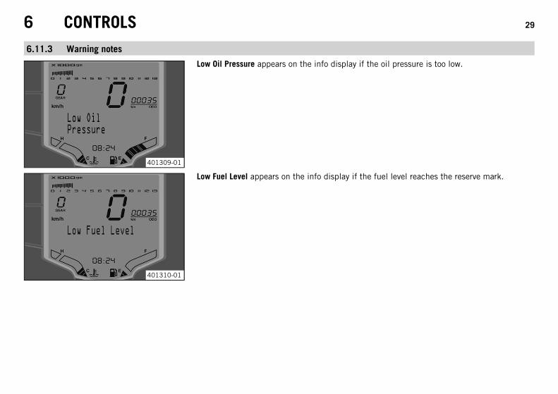
Low Oil Pressure appears on the info display if the oil pressure is too low.
401310-01
Low Fuel Level appears on the info display if the fuel level reaches the reserve mark.
6 CONTROLS 30
401311-01
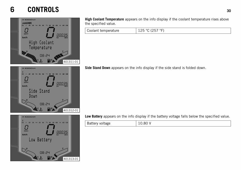
High Coolant Temperature appears on the info display if the coolant temperature rises abovethe specified value.
Coolant temperature 125 °C (257 °F)
401312-01
Side Stand Down appears on the info display if the side stand is folded down.
401313-01
Low Battery appears on the info display if the battery voltage falls below the specified value.
Battery voltage 10.80 V
6 CONTROLS 31
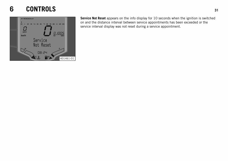
401461-01
Service Not Reset appears on the info display for 10 seconds when the ignition is switchedon and the distance interval between service appointments has been exceeded or theservice interval display was not reset during a service appointment.
6 CONTROLS 32
6.11.4 Function buttons
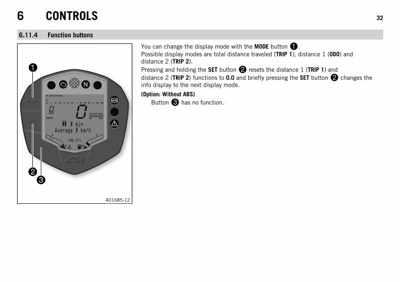
401685-12
You can change the display mode with the MODE button.Possible display modes are total distance traveled (TRIP 1), distance 1 (ODO) anddistance 2 (TRIP 2).Pressing and holding the SET button resets the distance 1 (TRIP 1) anddistance 2 (TRIP 2) functions to 0.0 and briefly pressing the SET button changes theinfo display to the next display mode.
(Option: Without ABS)Button has no function.
6 CONTROLS 33
6.11.5 Indicator lamps
401686-01
Possible states
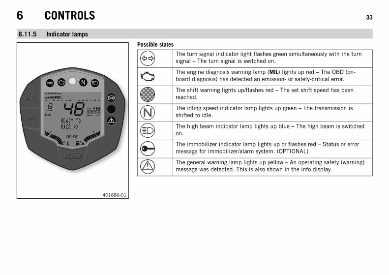
The turn signal indicator light flashes green simultaneously with the turnsignal – The turn signal is switched on.
The engine diagnosis warning lamp (MIL) lights up red – The OBD (on-board diagnosis) has detected an emission- or safety-critical error.
The shift warning lights up/flashes red – The set shift speed has beenreached.
The idling speed indicator lamp lights up green – The transmission isshifted to idle.
The high beam indicator lamp lights up blue – The high beam is switchedon.
The immobilizer indicator lamp lights up or flashes red – Status or errormessage for immobilizer/alarm system. (OPTIONAL)
The general warning lamp lights up yellow – An operating safety (warning)message was detected. This is also shown in the info display.
6 CONTROLS 34
6.11.6 Display
401685-11
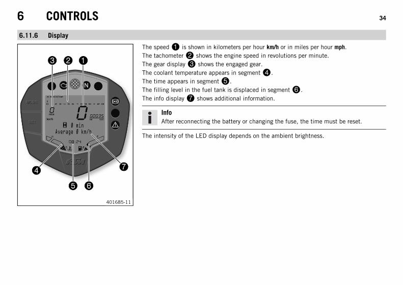
The speed is shown in kilometers per hour km/h or in miles per hour mph.The tachometer shows the engine speed in revolutions per minute.The gear display shows the engaged gear.The coolant temperature appears in segment.The time appears in segment.The filling level in the fuel tank is displaced in segment.The info display shows additional information.
InfoAfter reconnecting the battery or changing the fuse, the time must be reset.
The intensity of the LED display depends on the ambient brightness.
6 CONTROLS 35
6.11.7 Filling level display in fuel tank
401292-01
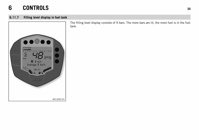
The filling level display consists of 9 bars. The more bars are lit, the more fuel is in the fueltank.
6 CONTROLS 36
6.11.8 TRIP F display
401293-01
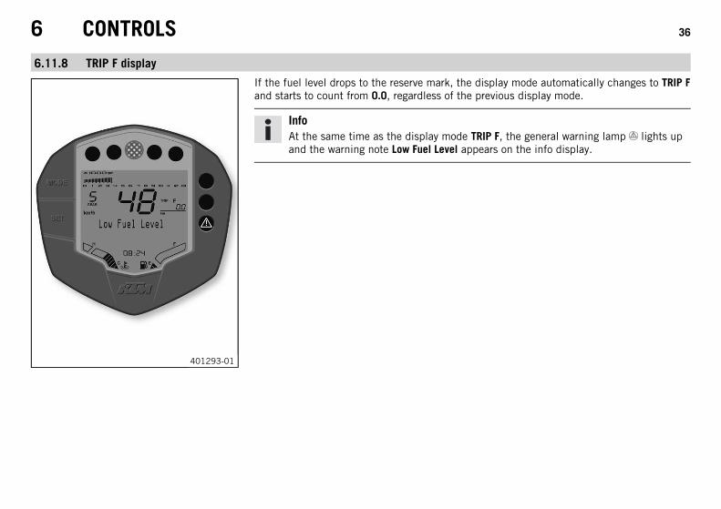
If the fuel level drops to the reserve mark, the display mode automatically changes to TRIP Fand starts to count from 0.0, regardless of the previous display mode.
InfoAt the same time as the display mode TRIP F, the general warning lamp lights upand the warning note Low Fuel Level appears on the info display.
6 CONTROLS 37
6.11.9 Coolant temperature indicator
401292-01
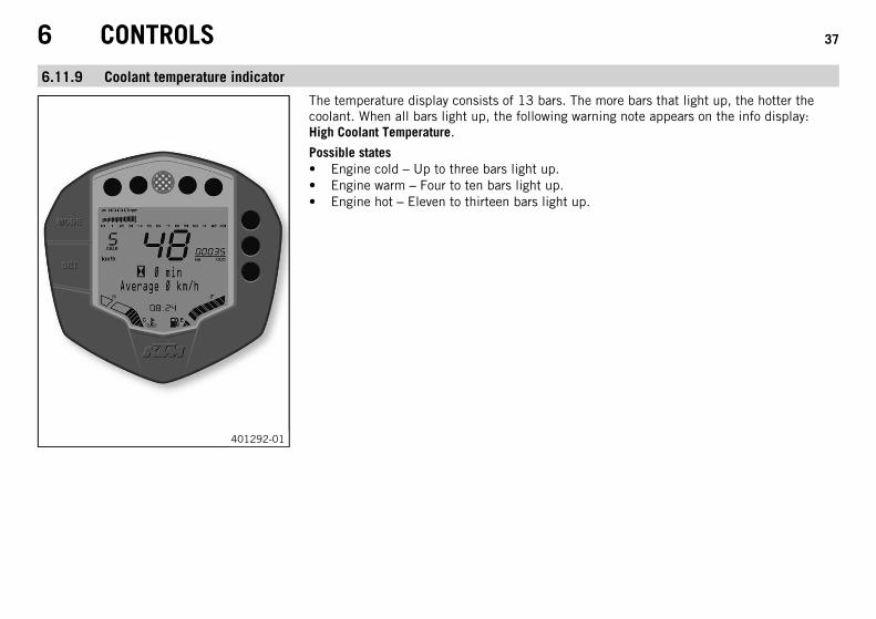
The temperature display consists of 13 bars. The more bars that light up, the hotter thecoolant. When all bars light up, the following warning note appears on the info display:High Coolant Temperature.
Possible states• Engine cold – Up to three bars light up.• Engine warm – Four to ten bars light up.• Engine hot – Eleven to thirteen bars light up.
6 CONTROLS 38
6.11.10 Info display
401291-10
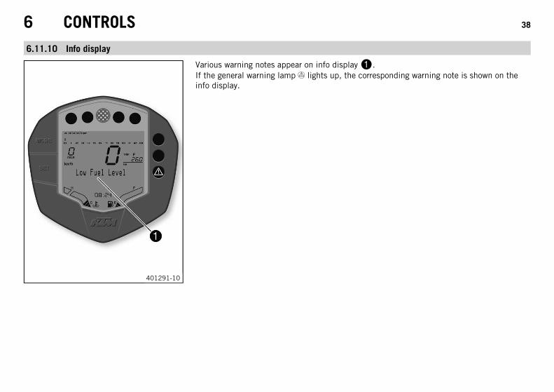
Various warning notes appear on info display.If the general warning lamp lights up, the corresponding warning note is shown on theinfo display.
6 CONTROLS 39
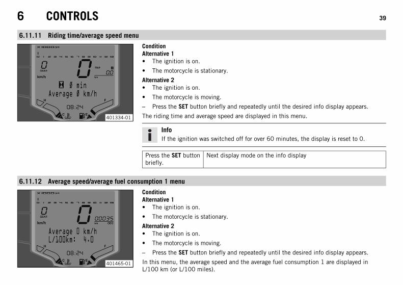
6.11.11 Riding time/average speed menu
401334-01
ConditionAlternative 1• The ignition is on.
• The motorcycle is stationary.
Alternative 2• The ignition is on.
• The motorcycle is moving.
– Press the SET button briefly and repeatedly until the desired info display appears.
The riding time and average speed are displayed in this menu.
InfoIf the ignition was switched off for over 60 minutes, the display is reset to 0.
Press the SET buttonbriefly.
Next display mode on the info display
6.11.12 Average speed/average fuel consumption 1 menu
401465-01
ConditionAlternative 1• The ignition is on.
• The motorcycle is stationary.
Alternative 2• The ignition is on.
• The motorcycle is moving.
– Press the SET button briefly and repeatedly until the desired info display appears.
In this menu, the average speed and the average fuel consumption 1 are displayed inL/100 km (or L/100 miles).
6 CONTROLS 40
InfoThe average fuel consumption 1 is displayed after several 100 meters of travel afterthe ignition is switched on.If the ignition was switched off for over 60 minutes, the display of the averagespeed and average fuel consumption 1 is reset to 0.
Press the SET buttonbriefly.
Next display mode on the info display
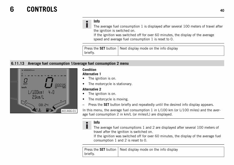
6.11.13 Average fuel consumption 1/average fuel consumption 2 menu
401466-01
ConditionAlternative 1• The ignition is on.
• The motorcycle is stationary.
Alternative 2• The ignition is on.
• The motorcycle is moving.
– Press the SET button briefly and repeatedly until the desired info display appears.
In this menu, the average fuel consumption 1 in L/100 km (or L/100 miles) and the aver-age fuel consumption 2 in km/L (or miles/L) are displayed.
InfoThe average fuel consumptions 1 and 2 are displayed after several 100 meters oftravel after the ignition is switched on.If the ignition was switched off for over 60 minutes, the display of the average fuelconsumption 1 and 2 is reset to 0.
Press the SET buttonbriefly.
Next display mode on the info display
6 CONTROLS 41
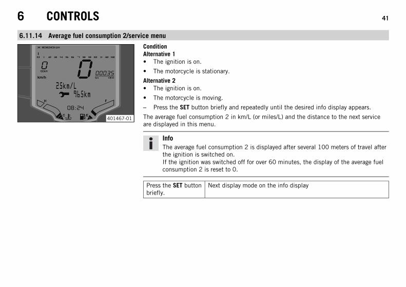
6.11.14 Average fuel consumption 2/service menu
401467-01
ConditionAlternative 1• The ignition is on.
• The motorcycle is stationary.
Alternative 2• The ignition is on.
• The motorcycle is moving.
– Press the SET button briefly and repeatedly until the desired info display appears.
The average fuel consumption 2 in km/L (or miles/L) and the distance to the next serviceare displayed in this menu.
InfoThe average fuel consumption 2 is displayed after several 100 meters of travel afterthe ignition is switched on.If the ignition was switched off for over 60 minutes, the display of the average fuelconsumption 2 is reset to 0.
Press the SET buttonbriefly.
Next display mode on the info display

6 CONTROLS 42
6.11.15 Service/range menu
401468-01
ConditionAlternative 1• The ignition is on.
• The motorcycle is stationary.
Alternative 2• The ignition is on.
• The motorcycle is moving.
– Press the SET button briefly and repeatedly until the desired info display appears.
This menu shows the distance to the next service and the range.
InfoThe range depends on the average fuel consumption and the fuel quantity in thefuel tank.The range is displayed after several 100 meters of travel after the ignition isswitched on.If the ignition was switched off for over 60 minutes, the display of the range andriding time is reset to 0.
Press the SET buttonbriefly.
Next display mode on the info display
6 CONTROLS 43
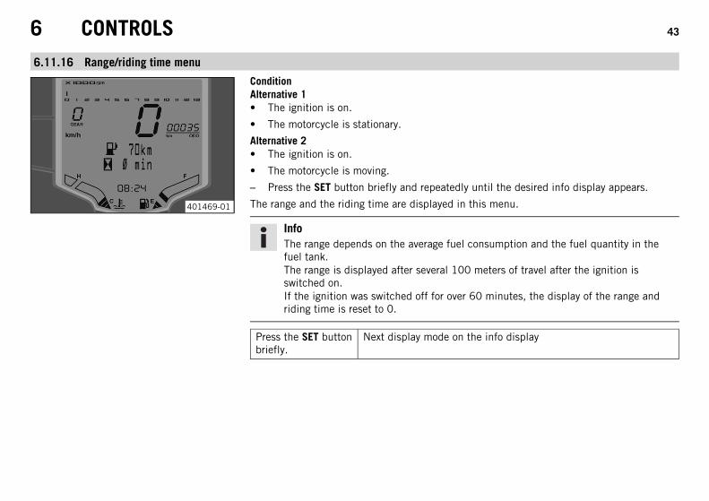
6.11.16 Range/riding time menu
401469-01
ConditionAlternative 1• The ignition is on.
• The motorcycle is stationary.
Alternative 2• The ignition is on.
• The motorcycle is moving.
– Press the SET button briefly and repeatedly until the desired info display appears.
The range and the riding time are displayed in this menu.
InfoThe range depends on the average fuel consumption and the fuel quantity in thefuel tank.The range is displayed after several 100 meters of travel after the ignition isswitched on.If the ignition was switched off for over 60 minutes, the display of the range andriding time is reset to 0.
Press the SET buttonbriefly.
Next display mode on the info display
6 CONTROLS 44
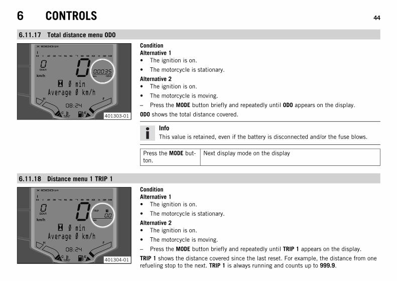
6.11.17 Total distance menu ODO
401303-01
ConditionAlternative 1• The ignition is on.
• The motorcycle is stationary.
Alternative 2• The ignition is on.
• The motorcycle is moving.
– Press the MODE button briefly and repeatedly until ODO appears on the display.
ODO shows the total distance covered.
InfoThis value is retained, even if the battery is disconnected and/or the fuse blows.
Press the MODE but-ton.
Next display mode on the display
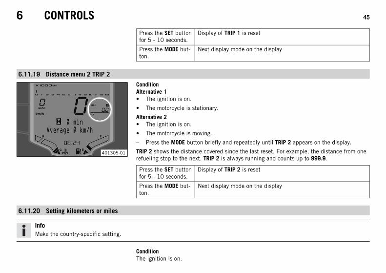
6.11.18 Distance menu 1 TRIP 1
401304-01
ConditionAlternative 1• The ignition is on.
• The motorcycle is stationary.
Alternative 2• The ignition is on.
• The motorcycle is moving.
– Press the MODE button briefly and repeatedly until TRIP 1 appears on the display.
TRIP 1 shows the distance covered since the last reset. For example, the distance from onerefueling stop to the next. TRIP 1 is always running and counts up to 999.9.
6 CONTROLS 45
Press the SET buttonfor 5 - 10 seconds.
Display of TRIP 1 is reset
Press the MODE but-ton.
Next display mode on the display
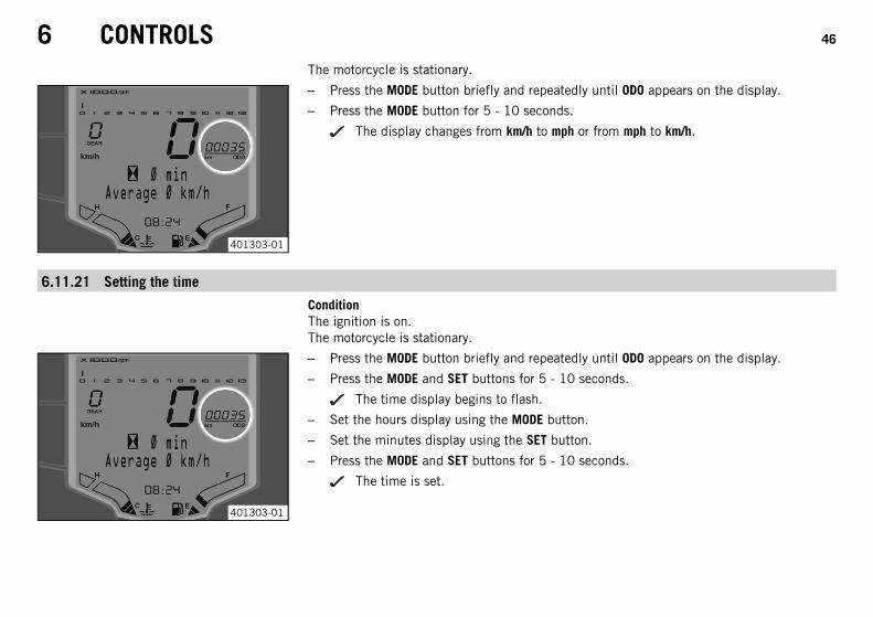
6.11.19 Distance menu 2 TRIP 2
401305-01
ConditionAlternative 1• The ignition is on.
• The motorcycle is stationary.
Alternative 2• The ignition is on.
• The motorcycle is moving.
– Press the MODE button briefly and repeatedly until TRIP 2 appears on the display.
TRIP 2 shows the distance covered since the last reset. For example, the distance from onerefueling stop to the next. TRIP 2 is always running and counts up to 999.9.
Press the SET buttonfor 5 - 10 seconds.
Display of TRIP 2 is reset
Press the MODE but-ton.
Next display mode on the display
6.11.20 Setting kilometers or miles
InfoMake the country-specific setting.
ConditionThe ignition is on.
6 CONTROLS 46
The motorcycle is stationary.
401303-01
– Press the MODE button briefly and repeatedly until ODO appears on the display.
– Press the MODE button for 5 - 10 seconds.
The display changes from km/h to mph or from mph to km/h.
6.11.21 Setting the time
ConditionThe ignition is on.The motorcycle is stationary.
401303-01
– Press the MODE button briefly and repeatedly until ODO appears on the display.
– Press the MODE and SET buttons for 5 - 10 seconds.
The time display begins to flash.
– Set the hours display using the MODE button.
– Set the minutes display using the SET button.
– Press the MODE and SET buttons for 5 - 10 seconds.
The time is set.
6 CONTROLS 47
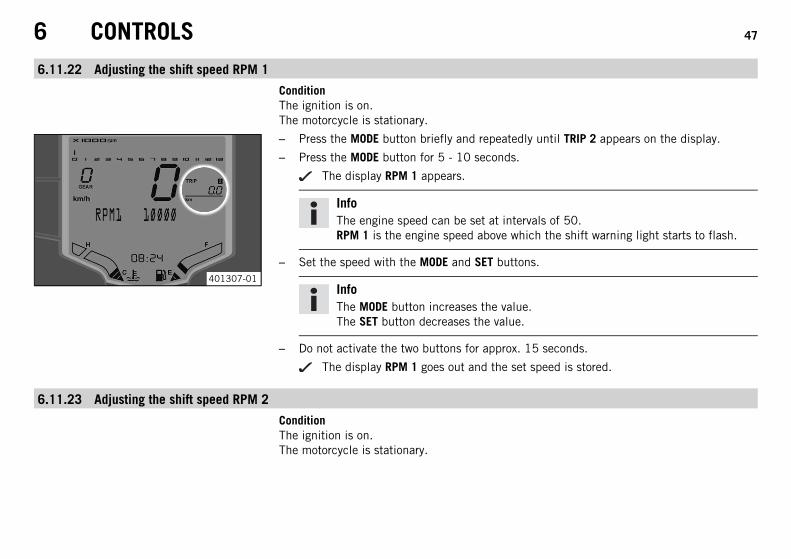
6.11.22 Adjusting the shift speed RPM 1
ConditionThe ignition is on.The motorcycle is stationary.
401307-01
– Press the MODE button briefly and repeatedly until TRIP 2 appears on the display.
– Press the MODE button for 5 - 10 seconds.
The display RPM 1 appears.
InfoThe engine speed can be set at intervals of 50.RPM 1 is the engine speed above which the shift warning light starts to flash.
– Set the speed with the MODE and SET buttons.
InfoThe MODE button increases the value.The SET button decreases the value.
– Do not activate the two buttons for approx. 15 seconds.
The display RPM 1 goes out and the set speed is stored.
6.11.23 Adjusting the shift speed RPM 2
ConditionThe ignition is on.The motorcycle is stationary.
6 CONTROLS 48
401308-01
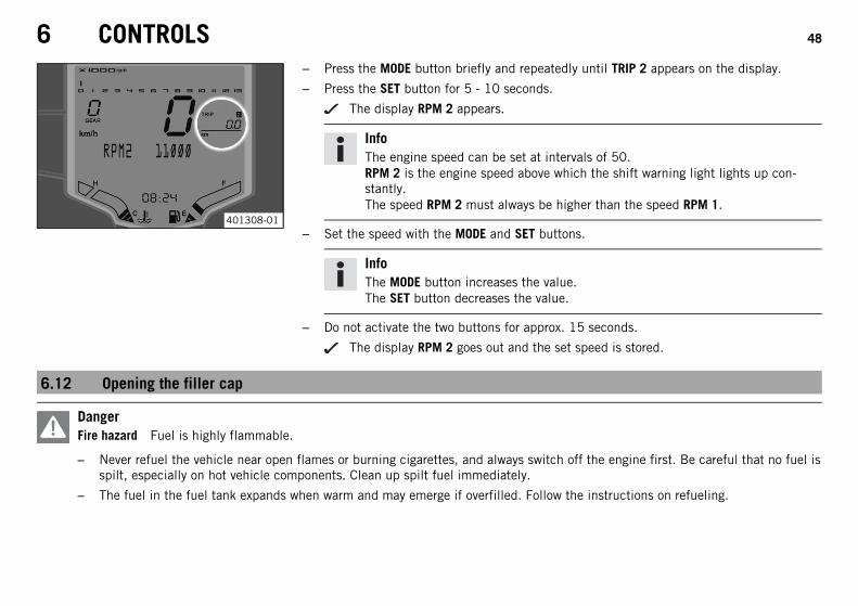
– Press the MODE button briefly and repeatedly until TRIP 2 appears on the display.
– Press the SET button for 5 - 10 seconds.
The display RPM 2 appears.
InfoThe engine speed can be set at intervals of 50.RPM 2 is the engine speed above which the shift warning light lights up con-stantly.The speed RPM 2 must always be higher than the speed RPM 1.
– Set the speed with the MODE and SET buttons.
InfoThe MODE button increases the value.The SET button decreases the value.
– Do not activate the two buttons for approx. 15 seconds.
The display RPM 2 goes out and the set speed is stored.
6.12 Opening the filler cap
DangerFire hazard Fuel is highly flammable.
– Never refuel the vehicle near open flames or burning cigarettes, and always switch off the engine first. Be careful that no fuel isspilt, especially on hot vehicle components. Clean up spilt fuel immediately.
– The fuel in the fuel tank expands when warm and may emerge if overfilled. Follow the instructions on refueling.
6 CONTROLS 49
WarningDanger of poisoning Fuel is poisonous and a health hazard.
– Fuel must not come into contact with the skin, eyes, or clothing. Do not breathe in the fuel vapors. If contact occurs with theeyes, rinse with water immediately and contact a physician. Immediately clean contaminated areas on the skin with soap andwater. If fuel is swallowed, contact a physician immediately. Change clothing that is contaminated with fuel. Store fuel properlyin a suitable canister and keep away from children.
WarningEnvironmental hazard Improper handling of fuel is a danger to the environment.
– Do not allow fuel to get into the ground water, the ground, or the sewage system.
B00710-10
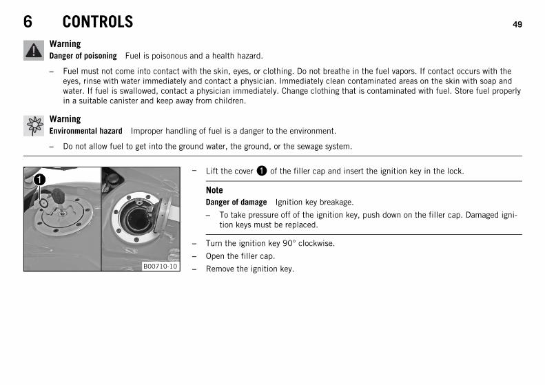
– Lift the cover of the filler cap and insert the ignition key in the lock.
NoteDanger of damage Ignition key breakage.
– To take pressure off of the ignition key, push down on the filler cap. Damaged igni-tion keys must be replaced.
– Turn the ignition key 90° clockwise.
– Open the filler cap.
– Remove the ignition key.
6 CONTROLS 50
6.13 Closing the filler cap
B00711-01
WarningFire hazard Fuel is highly flammable, poisonous and harmful to your health.
– After closing the filler cap, ensure that it is locked properly. Change cloth-ing that has been contaminated with fuel. Immediately clean contaminatedareas on the skin with soap and water.
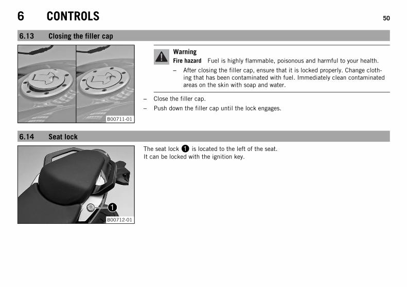
– Close the filler cap.
– Push down the filler cap until the lock engages.
6.14 Seat lock
B00712-01
The seat lock is located to the left of the seat.It can be locked with the ignition key.
6 CONTROLS 51
6.15 Tool set
B00758-10
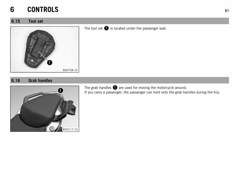
The tool set is located under the passenger seat.
6.16 Grab handles
B00717-10
The grab handles are used for moving the motorcycle around.If you carry a passenger, the passenger can hold onto the grab handles during the trip.
6 CONTROLS 52
6.17 Passenger footrests
B00713-01
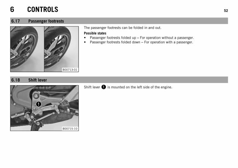
The passenger footrests can be folded in and out.
Possible states• Passenger footrests folded up – For operation without a passenger.• Passenger footrests folded down – For operation with a passenger.
6.18 Shift lever
B00715-10
Shift lever is mounted on the left side of the engine.
6 CONTROLS 53
B00716-10
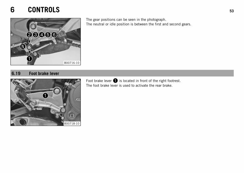
The gear positions can be seen in the photograph.The neutral or idle position is between the first and second gears.
6.19 Foot brake lever
B00718-10
Foot brake lever is located in front of the right footrest.The foot brake lever is used to activate the rear brake.

6 CONTROLS 54
6.20 Side stand
B00714-10
The side stand is on the left side of the vehicle.The side stand is used to park the motorcycle.
InfoThe side stand must be folded up during motorcycle use.Side stand is coupled with the safety start system; see the riding instructions.
Possible states• Side stand folded out – The vehicle can be leaned on the side stand. The safety start
system is active.• Side stand folded in – This position is mandatory for all trips. The safety start system
is inactive.
7 PREPARING FOR USE 55
7.1 Advice on first use
DangerDanger of accidents Danger arising from the rider's judgement being impaired.
– Do not operate the vehicle while under the influence of alcohol, drugs and certain medications or physically or mentallyimpaired.
WarningRisk of injury Missing or poor protective clothing presents an increased safety risk.
– Wear protective clothing (helmet, boots, gloves, pants and jacket with protectors) every time you ride the vehicle. Always wearprotective clothing that is in good condition and meets the legal requirements.
WarningDanger of crashing Poor vehicle handling due to different tire tread patterns on front and rear wheels.
– The front and rear wheels must be fitted with tires with similar tread patterns to prevent loss of control over the vehicle.
WarningDanger of accidents Uncontrollable handling characteristic due to non-approved and/or non-recommended tires/wheels.
– Only tires/wheels approved by KTM and with the corresponding speed index should be used.
WarningDanger of accidents Reduced road grip with new tires.
– New tires have a smooth rolling surface and therefore cannot provide full road grip. The entire rolling surface must be rough-ened in the first 200 kilometers (124.3 miles) by moderate riding at alternating angles. The full grip levels are not achieveduntil the tires have been run in.
InfoWhen using your vehicle, remember that others may feel disturbed by excessive noise.
7 PREPARING FOR USE 56
– Make sure that the pre-delivery inspection work has been carried out by an authorized KTM workshop.
You receive a delivery certificate and the service record at vehicle handover.
– Before your first trip, read the entire operating instructions carefully.
– Get to know the controls.
– Get used to handling the motorcycle on a suitable piece of land before making a longer trip. Try also to ride as slowly as possible to geta better feel for the vehicle.
– Hold the handlebar firmly with both hands and keep your feet on the footrests when riding.
– Run the engine in. ( p. 56)
7.2 Running in the engine– During the running-in phase, do not exceed the specified engine speed.
Guideline
Maximum engine speed
During the first: 1,000 km (620 mi) 7,500 rpm
TipDuring the running-in phase, set the shift warning light to the specified engine speed.
– Adjust the shift speed RPM 1. ( p. 47)
– Adjust the shift speed RPM 2. ( p. 47)
– Avoid fully opening the throttle!
7 PREPARING FOR USE 57
7.3 Loading the vehicle
WarningDanger of accidents Unstable handling characteristics.
– Do not exceed the maximum permitted weight and axle loads. The overall weight consists of: motorcycle operational and with afull tank, driver and passenger with protective clothing and helmet, baggage.
WarningDanger of accidents Unstable handling characteristics due to incorrect mounting of suitcase and/or tank rucksack.
– Mount and secure suitcase and tank rucksack according to the manufacturer's instructions.
WarningDanger of accidents Risk of breakage of suitcase system.
– If you have fitted suitcases on your motorcycle, read the manufacturer's specifications concerning the maximum payload.
WarningDanger of accidents Poor visibility for other road users due to slipped baggage.
– If the tail light is covered, you are less visible to traffic behind you, especially in the dark. Check that your baggage is fixedproperly at regular intervals.
WarningDanger of accidents Changed handling characteristics and longer stopping distance with excessive payload.
– Adapt your speed according to your payload.
WarningDanger of accidents Unstable handling characteristics due to slipped baggage.
– Check the way your baggage is fixed regularly.
7 PREPARING FOR USE 58
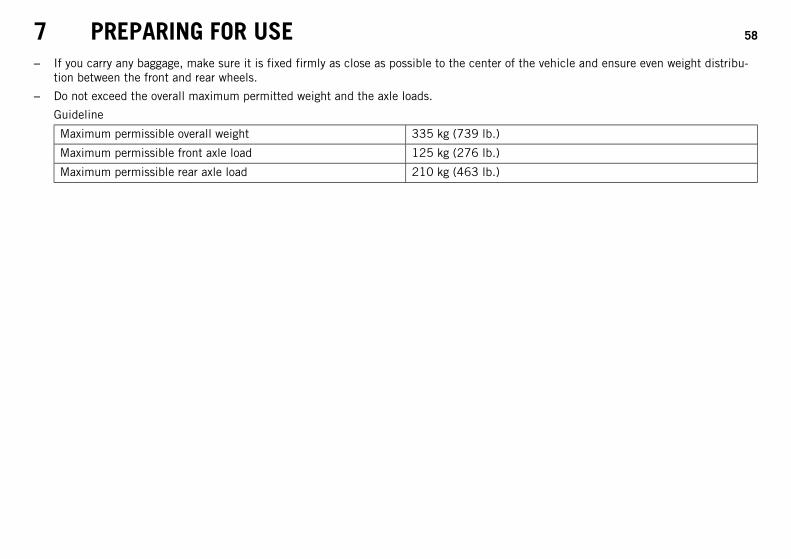
– If you carry any baggage, make sure it is fixed firmly as close as possible to the center of the vehicle and ensure even weight distribu-tion between the front and rear wheels.
– Do not exceed the overall maximum permitted weight and the axle loads.
Guideline
Maximum permissible overall weight 335 kg (739 lb.)
Maximum permissible front axle load 125 kg (276 lb.)
Maximum permissible rear axle load 210 kg (463 lb.)
8 RIDING INSTRUCTIONS 59
8.1 Checks and maintenance when preparing for use
InfoBefore every trip, check the condition of the vehicle and ensure that it is roadworthy.The vehicle must be in perfect technical condition when used.
– Check the engine oil level. ( p. 139)
– Check the brake fluid level of the front brake. ( p. 91)
– Check the rear brake fluid level. ( p. 97)
– Check the front brake linings. ( p. 94)
– Check the rear brake linings. ( p. 99)
– Check the brake system function.
– Check the coolant level. ( p. 131)
– Check for chain dirt accumulation. ( p. 80)
– Check the chain tension. ( p. 81)
– Check the tire condition. ( p. 108)
– Check the tire air pressure. ( p. 109)
– Check the settings of all controls and ensure that they can be operated smoothly.
– Check the functioning of the electrical equipment.
– Check that baggage is correctly secured.
– Sit on the motorcycle and check the rear mirror setting.
– Check the fuel level.
8 RIDING INSTRUCTIONS 60
8.2 Starting
DangerDanger of poisoning Exhaust gases are toxic and inhaling them may result in unconsciousness and/or death.
– When running the engine, always make sure there is sufficient ventilation, and do not start or run the engine in an enclosedspace without an effective exhaust extraction system.
CautionDanger of accidents If the vehicle is operated with a discharged battery or without a battery, electronic components and safetyequipment may be damaged.
– Never operate the vehicle with a discharged battery or without a battery.
NoteEngine failure Unfiltered intake air has a negative effect on the service life of the engine.
– Never operate the vehicle without an air filter as dust and dirt will enter the engine and lead to increased wear.
NoteEngine failure High engine speeds in cold engines have a negative effect on the service life of the engine.
– Always warm up the engine at low engine speeds.
8 RIDING INSTRUCTIONS 61
B00782-10
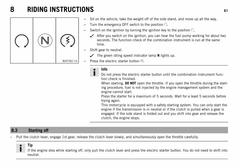
– Sit on the vehicle, take the weight off of the side stand, and move up all the way.
– Turn the emergency OFF switch to the position .
– Switch on the ignition by turning the ignition key to the position .
After you switch on the ignition, you can hear the fuel pump working for about twoseconds. The function check of the combination instrument is run at the sametime.
– Shift gear to neutral.
The green idling speed indicator lamp N lights up.
– Press the electric starter button .
InfoDo not press the electric starter button until the combination instrument func-tion check is finished.When starting, DO NOT open the throttle. If you open the throttle during the start-ing procedure, fuel is not injected by the engine management system and theengine cannot start.Press the starter for a maximum of 5 seconds. Wait for a least 5 seconds beforetrying again.This motorcycle is equipped with a safety starting system. You can only start theengine if the transmission is in neutral or if the clutch is pulled when a gear isengaged. If the side stand is folded out and you shift into gear and release theclutch, the engine stops.
8.3 Starting off– Pull the clutch lever, engage 1st gear, release the clutch lever slowly, and simultaneously open the throttle carefully.
TipIf the engine dies while starting off, only pull the clutch lever and press the electric starter button. You do not need to shift intoneutral.
8 RIDING INSTRUCTIONS 62
8.4 Shifting, riding
WarningDanger of accidents Abrupt load alterations can cause the vehicle to get out of control.
– Avoid abrupt load alterations and sudden braking actions, and adapt your speed to the road conditions.
WarningDanger of accidents If you change down at high engine speed, the rear wheel can lock up.
– Do not change into a low gear at high engine speed. The engine races and the rear wheel can lock up.
WarningDanger of accidents Malfunctions caused by incorrect ignition key position.
– Do not change the ignition key position during a journey.
WarningDanger of accidents Distraction from traffic activity by adjustments to the vehicle.
– Make all adjustments when the vehicle is at a standstill.
WarningRisk of injury Falling off of the passenger.
– The passenger must be seated properly on the passenger seat and hold on to the front rider or the grab handles. The feet mustbe positioned on the passenger footrests. Note the regulations governing the minimum age of passengers.
WarningDanger of accidents Danger of accidents caused by dangerous driving.
– Comply with traffic regulations and ride defensively and foresightedly to detect sources of danger early on.
8 RIDING INSTRUCTIONS 63
WarningDanger of accidents Reduced road grip with cold tires.
– On every journey, take the first miles carefully at moderate speed until the tires reach operating temperature and optimal roadgrip is ensured.
WarningDanger of accidents Reduced road grip with new tires.
– New tires have a smooth rolling surface and therefore cannot provide full road grip. The entire rolling surface must be rough-ened in the first 200 kilometers (124.3 miles) by moderate riding at alternating angles. The full grip levels are not achieveduntil the tires have been run in.
WarningDanger of accidents Unstable handling characteristics due to slipped baggage.
– Check the way your baggage is fixed regularly.
WarningDanger of accidents Lack of roadworthiness.
– After a fall, check the vehicle as usual before preparing for use.
NoteEngine failure Overheating of engine.
– If the coolant temperature warning lamp lights up, stop and switch off the engine. Allow the engine to cool down and check thecoolant level in the radiator, and top up if necessary. If you continue with the coolant temperature warning lamp alight, you may haveengine failure.
InfoIf you hear unusual noises while riding, stop immediately, switch off the engine and contact an authorized KTM workshop.
8 RIDING INSTRUCTIONS 64
B00716-10
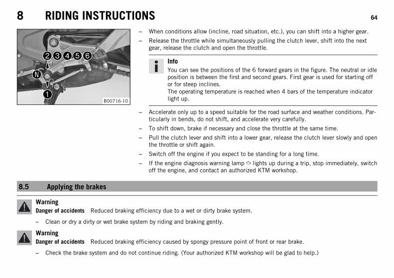
– When conditions allow (incline, road situation, etc.), you can shift into a higher gear.
– Release the throttle while simultaneously pulling the clutch lever, shift into the nextgear, release the clutch and open the throttle.
InfoYou can see the positions of the 6 forward gears in the figure. The neutral or idleposition is between the first and second gears. First gear is used for starting offor for steep inclines.The operating temperature is reached when 4 bars of the temperature indicatorlight up.
– Accelerate only up to a speed suitable for the road surface and weather conditions. Par-ticularly in bends, do not shift, and accelerate very carefully.
– To shift down, brake if necessary and close the throttle at the same time.
– Pull the clutch lever and shift into a lower gear, release the clutch lever slowly and openthe throttle or shift again.
– Switch off the engine if you expect to be standing for a long time.
– If the engine diagnosis warning lamp lights up during a trip, stop immediately, switchoff the engine, and contact an authorized KTM workshop.
8.5 Applying the brakes
WarningDanger of accidents Reduced braking efficiency due to a wet or dirty brake system.
– Clean or dry a dirty or wet brake system by riding and braking gently.
WarningDanger of accidents Reduced braking efficiency caused by spongy pressure point of front or rear brake.
– Check the brake system and do not continue riding. (Your authorized KTM workshop will be glad to help.)
8 RIDING INSTRUCTIONS 65
WarningDanger of accidents Failure of brake system.
– If the foot brake lever is not released, the brake linings drag continuously. The rear brake may fail due to overheating. Take yourfoot off the foot brake lever when you are not braking.
WarningDanger of accidents Longer stopping distance due to higher overall weight.
– Take the longer stopping distance into account when carrying a passenger and baggage.
WarningDanger of accidents Delayed brake action on salted roads.
– There may be salt deposits on the brake discs. In order to restore the normal braking efficiency, you will need to remove thedeposits from the discs by carefully applying the brakes.
(Option: Without ABS)
WarningDanger of accidents If you brake too hard, the wheels can lock.
– Adapt your braking to the traffic situation and the road conditions.
– When braking, release the throttle and apply the front and rear brakes at the same time.
– On sandy, wet, or slippery surfaces, use the rear brake.
– Braking should always be completed before you go into a bend. Change down to a lower gear appropriate to your road speed.
– On long downhill stretches, use the braking effect of the engine. Change down one or two gears, but do not over rev the engine. Inthis way, you have to brake far less and the brakes do not overheat.
8 RIDING INSTRUCTIONS 66
8.6 Stopping, parking
WarningRisk of misappropriation Usage by unauthorized persons.
– Never leave the vehicle while the engine is running. Secure the vehicle against use by unauthorized persons. If you leave thevehicle, lock the steering and remove the ignition key.
WarningDanger of burns Some vehicle components become very hot when the vehicle is operated.
– Do not touch hot components such as exhaust system, radiator, engine, shock absorber, and the brake system. Allow thesecomponents to cool down before starting work on them.
NoteDanger of damage The parked vehicle may roll away or fall over.
– Always place the vehicle on a firm and even surface.
NoteFire hazard Some vehicle components become very hot when the vehicle is operated.
– Do not park the vehicle near flammable or explosive substances. Do not place objects on the vehicle while it is still warm from beingrun. Always let the vehicle cool first.
NoteMaterial damage Damage to or destruction of components due to excessive load.
– The side stand is only designed for the weight of the motorcycle. Do no sit on the motorcycle when it is resting on the side stand. Theside stand or the frame may become damaged and the motorcycle may fall over.
– Brake the motorcycle.
– Shift gear to neutral.
8 RIDING INSTRUCTIONS 67
– Switch off the ignition by turning the ignition key to the position .
InfoIf the engine is switched off with the emergency OFF switch and the ignition remains switched on at the ignition lock, powercontinues to flow to most power consumers and the battery will discharge. You should therefore always switch off the enginewith the ignition key - the emergency OFF switch is intended for emergencies only.
– Park the motorcycle on a firm surface.
– Swing the side stand forward with your foot as far as it will go and lean the vehicle on it.
– Lock the steering by turning the handlebar fully to the left, pressing down the ignition key to position and turning it to position .To make the steering lock engage more easily, move the handlebar a little to the left and right. Remove the ignition key.
8.7 Transport
NoteDanger of damage The parked vehicle may roll away or fall over.
– Always place the vehicle on a firm and even surface.
NoteFire hazard Some vehicle components become very hot when the vehicle is operated.
– Do not park the vehicle near flammable or explosive substances. Do not place objects on the vehicle while it is still warm from beingrun. Always let the vehicle cool first.
8 RIDING INSTRUCTIONS 68
401448-01
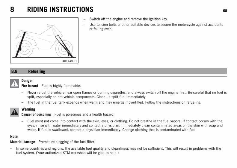
– Switch off the engine and remove the ignition key.
– Use tension belts or other suitable devices to secure the motorcycle against accidentsor falling over.
8.8 Refueling
DangerFire hazard Fuel is highly flammable.
– Never refuel the vehicle near open flames or burning cigarettes, and always switch off the engine first. Be careful that no fuel isspilt, especially on hot vehicle components. Clean up spilt fuel immediately.
– The fuel in the fuel tank expands when warm and may emerge if overfilled. Follow the instructions on refueling.
WarningDanger of poisoning Fuel is poisonous and a health hazard.
– Fuel must not come into contact with the skin, eyes, or clothing. Do not breathe in the fuel vapors. If contact occurs with theeyes, rinse with water immediately and contact a physician. Immediately clean contaminated areas on the skin with soap andwater. If fuel is swallowed, contact a physician immediately. Change clothing that is contaminated with fuel.
NoteMaterial damage Premature clogging of the fuel filter.
– In some countries and regions, the available fuel quality and cleanliness may not be sufficient. This will result in problems with thefuel system. (Your authorized KTM workshop will be glad to help.)
8 RIDING INSTRUCTIONS 69
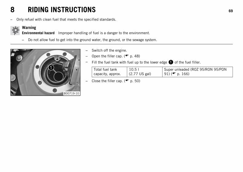
– Only refuel with clean fuel that meets the specified standards.
WarningEnvironmental hazard Improper handling of fuel is a danger to the environment.
– Do not allow fuel to get into the ground water, the ground, or the sewage system.
B00719-10
– Switch off the engine.
– Open the filler cap. ( p. 48)
– Fill the fuel tank with fuel up to the lower edge of the fuel filler.
Total fuel tankcapacity, approx.
10.5 l(2.77 US gal)
Super unleaded (ROZ 95/RON 95/PON91) ( p. 166)
– Close the filler cap. ( p. 50)
9 SERVICE SCHEDULE 70
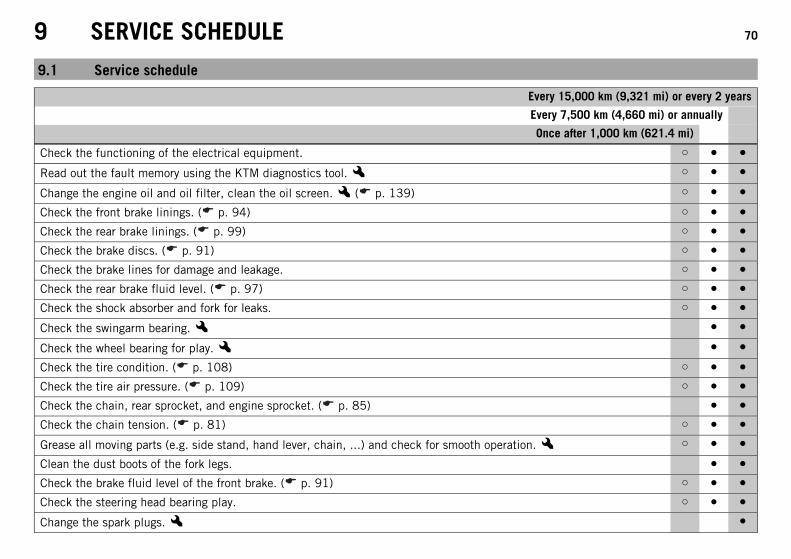
9.1 Service schedule
Every 15,000 km (9,321 mi) or every 2 years
Every 7,500 km (4,660 mi) or annually
Once after 1,000 km (621.4 mi)
Check the functioning of the electrical equipment. ○ ● ●
Read out the fault memory using the KTM diagnostics tool.x ○ ● ●
Change the engine oil and oil filter, clean the oil screen.x ( p. 139) ○ ● ●
Check the front brake linings. ( p. 94) ○ ● ●
Check the rear brake linings. ( p. 99) ○ ● ●
Check the brake discs. ( p. 91) ○ ● ●
Check the brake lines for damage and leakage. ○ ● ●
Check the rear brake fluid level. ( p. 97) ○ ● ●
Check the shock absorber and fork for leaks. ○ ● ●
Check the swingarm bearing.x ● ●
Check the wheel bearing for play.x ● ●
Check the tire condition. ( p. 108) ○ ● ●
Check the tire air pressure. ( p. 109) ○ ● ●
Check the chain, rear sprocket, and engine sprocket. ( p. 85) ● ●
Check the chain tension. ( p. 81) ○ ● ●
Grease all moving parts (e.g. side stand, hand lever, chain, ...) and check for smooth operation.x ○ ● ●
Clean the dust boots of the fork legs. ● ●
Check the brake fluid level of the front brake. ( p. 91) ○ ● ●
Check the steering head bearing play. ○ ● ●
Change the spark plugs.x ●
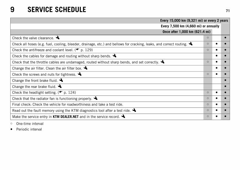
9 SERVICE SCHEDULE 71
Every 15,000 km (9,321 mi) or every 2 years
Every 7,500 km (4,660 mi) or annually
Once after 1,000 km (621.4 mi)
Check the valve clearance.x ○ ●
Check all hoses (e.g. fuel, cooling, bleeder, drainage, etc.) and bellows for cracking, leaks, and correct routing.x ○ ● ●
Check the antifreeze and coolant level. ( p. 129) ○ ● ●
Check the cables for damage and routing without sharp bends.x ● ●
Check that the throttle cables are undamaged, routed without sharp bends, and set correctly.x ○ ● ●
Change the air filter. Clean the air filter box.x ● ●
Check the screws and nuts for tightness.x ○ ● ●
Change the front brake fluid.x ●
Change the rear brake fluid.x ●
Check the headlight setting. ( p. 124) ○ ● ●
Check that the radiator fan is functioning properly.x ○ ● ●
Final check: Check the vehicle for roadworthiness and take a test ride. ○ ● ●
Read out the fault memory using the KTM diagnostics tool after a test ride.x ○ ● ●
Make the service entry in KTM DEALER.NET and in the service record.x ○ ● ●
○ One-time interval
● Periodic interval
10 TUNING THE CHASSIS 72
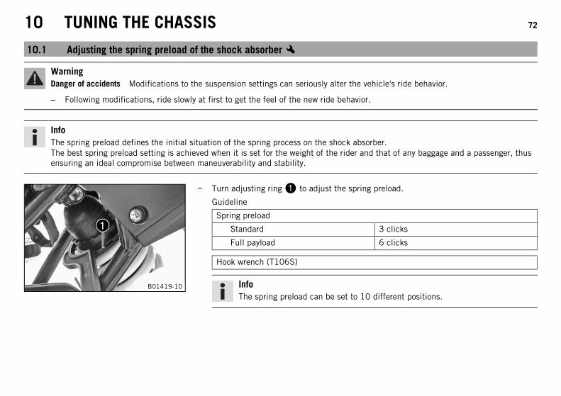
10.1 Adjusting the spring preload of the shock absorberx
WarningDanger of accidents Modifications to the suspension settings can seriously alter the vehicle's ride behavior.
– Following modifications, ride slowly at first to get the feel of the new ride behavior.
InfoThe spring preload defines the initial situation of the spring process on the shock absorber.The best spring preload setting is achieved when it is set for the weight of the rider and that of any baggage and a passenger, thusensuring an ideal compromise between maneuverability and stability.
B01419-10
– Turn adjusting ring to adjust the spring preload.
Guideline
Spring preload
Standard 3 clicks
Full payload 6 clicks
Hook wrench (T106S)
InfoThe spring preload can be set to 10 different positions.
10 TUNING THE CHASSIS 73
10.2 Adjusting the shift lever
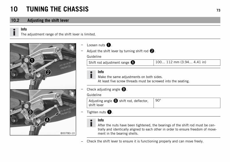
InfoThe adjustment range of the shift lever is limited.
B00780-10
– Loosen nuts.
– Adjust the shift lever by turning shift rod.
Guideline
Shift rod adjustment range 100… 112 mm (3.94… 4.41 in)
InfoMake the same adjustments on both sides.At least five screw threads must be screwed into the seating.
– Check adjusting angle.
Guideline
Adjusting angle shift rod, deflector,shift lever
90°
– Tighten nuts.
InfoAfter the nuts have been tightened, the bearings of the shift rod must be cen-trally and identically aligned to each other in order to ensure freedom of move-ment in the bearing shells.
– Check the shift lever to ensure it is functioning properly and can move freely.
11 SERVICE WORK ON THE CHASSIS 74
11.1 Raising the motorcycle with the rear wheel stand
NoteDanger of damage The parked vehicle may roll away or fall over.
– Always place the vehicle on a firm and even surface.
C00670-01
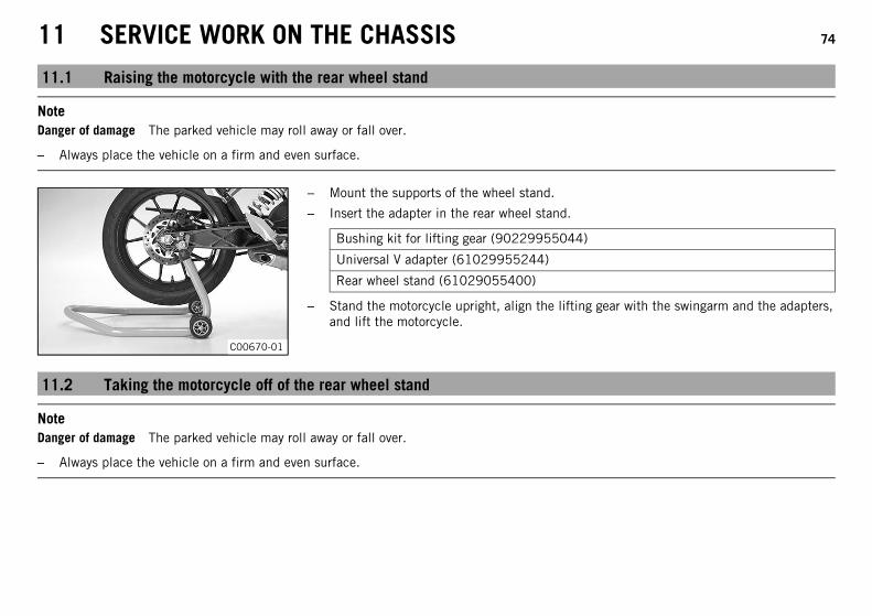
– Mount the supports of the wheel stand.
– Insert the adapter in the rear wheel stand.
Bushing kit for lifting gear (90229955044)
Universal V adapter (61029955244)
Rear wheel stand (61029055400)
– Stand the motorcycle upright, align the lifting gear with the swingarm and the adapters,and lift the motorcycle.
11.2 Taking the motorcycle off of the rear wheel stand
NoteDanger of damage The parked vehicle may roll away or fall over.
– Always place the vehicle on a firm and even surface.
11 SERVICE WORK ON THE CHASSIS 75
B00714-10
– Secure the motorcycle against falling over.
– Remove the rear wheel stand and lean the vehicle on the side stand.
– Remove the support of the wheel stand.
11.3 Raising the motorcycle with the front wheel stand
NoteDanger of damage The parked vehicle may roll away or fall over.
– Always place the vehicle on a firm and even surface.
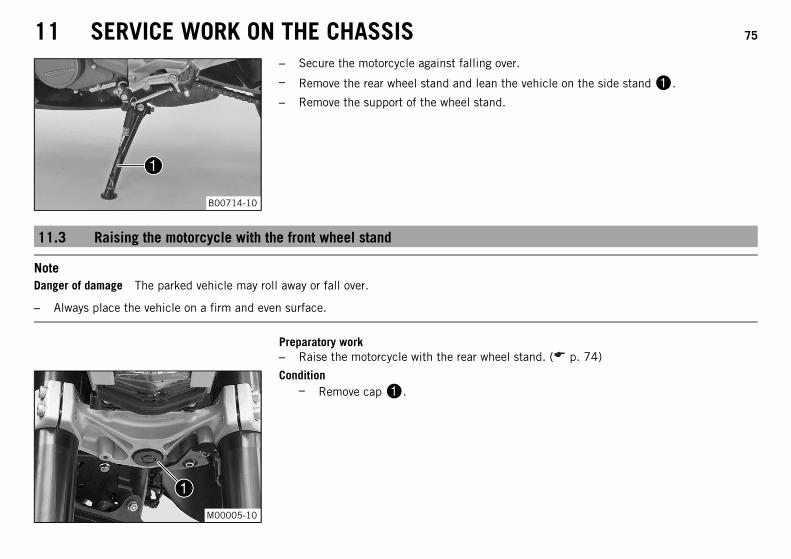
Preparatory work– Raise the motorcycle with the rear wheel stand. ( p. 74)
M00005-10
Condition– Remove cap.
11 SERVICE WORK ON THE CHASSIS 76
C00197-01
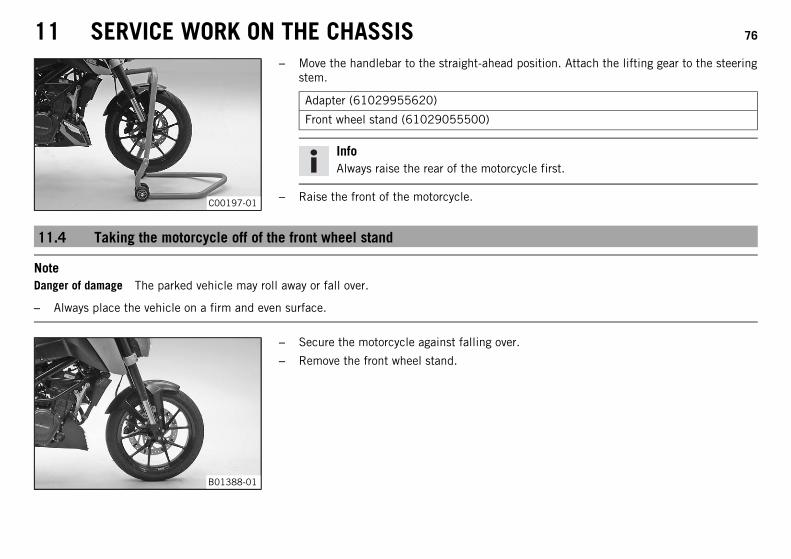
– Move the handlebar to the straight-ahead position. Attach the lifting gear to the steeringstem.
Adapter (61029955620)
Front wheel stand (61029055500)
InfoAlways raise the rear of the motorcycle first.
– Raise the front of the motorcycle.
11.4 Taking the motorcycle off of the front wheel stand
NoteDanger of damage The parked vehicle may roll away or fall over.
– Always place the vehicle on a firm and even surface.
B01388-01
– Secure the motorcycle against falling over.
– Remove the front wheel stand.
11 SERVICE WORK ON THE CHASSIS 77
M00005-10
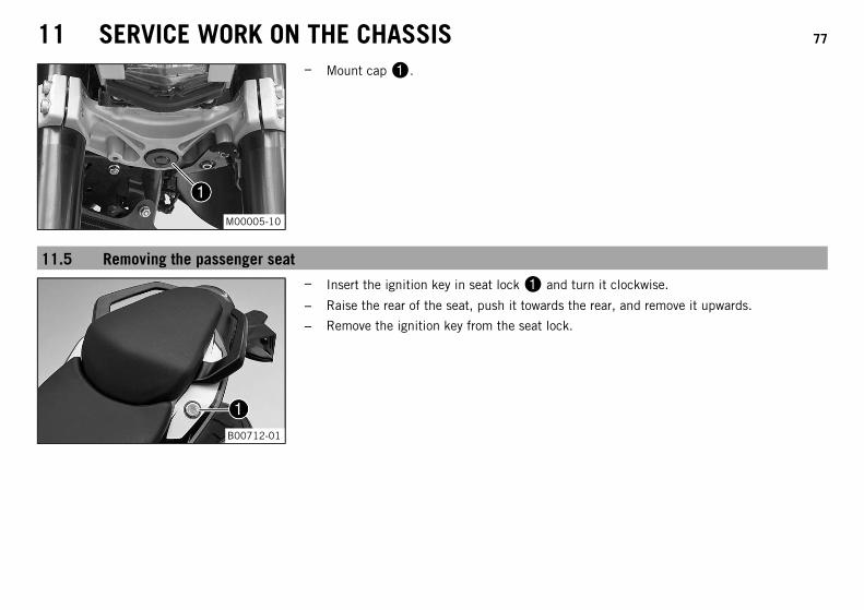
– Mount cap.
11.5 Removing the passenger seat
B00712-01
– Insert the ignition key in seat lock and turn it clockwise.
– Raise the rear of the seat, push it towards the rear, and remove it upwards.
– Remove the ignition key from the seat lock.
11 SERVICE WORK ON THE CHASSIS 78
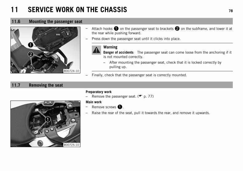
11.6 Mounting the passenger seat
B00724-10
– Attach hooks on the passenger seat to brackets on the subframe, and lower it atthe rear while pushing forward.
– Press down the passenger seat until it clicks into place.
WarningDanger of accidents The passenger seat can come loose from the anchoring if itis not mounted correctly.
– After mounting the passenger seat, check that it is locked correctly bypulling up.
– Finally, check that the passenger seat is correctly mounted.
11.7 Removing the seatPreparatory work– Remove the passenger seat. ( p. 77)
B00725-10
Main work– Remove screws.
– Raise the rear of the seat, pull it towards the rear, and remove it upwards.
11 SERVICE WORK ON THE CHASSIS 79
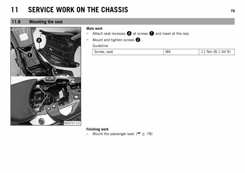
11.8 Mounting the seat
B00727-10
Main work– Attach seat recesses at screws and lower at the rear.
– Mount and tighten screws.
Guideline
Screw, seat M6 11 Nm (8.1 lbf ft)
Finishing work– Mount the passenger seat. ( p. 78)

11 SERVICE WORK ON THE CHASSIS 80
11.9 Checking for chain dirt accumulation
400678-01
– Check the chain for coarse dirt accumulation.
» If the chain is very dirty:
– Clean the chain. ( p. 80)
11.10 Cleaning the chain
WarningDanger of accidents Oil or grease on the tires reduces their grip.
– Remove oil and grease with a suitable cleaning material.
WarningDanger of accidents Reduced braking efficiency due to oil or grease on the brake discs.
– Always keep the brake discs free of oil and grease, and clean them with brake cleaner when necessary.
WarningEnvironmental hazard Hazardous substances cause environmental damage.
– Oil, grease, filters, fuel, cleaners, brake fluid, etc., should be disposed of as stipulated in applicable regulations.
11 SERVICE WORK ON THE CHASSIS 81
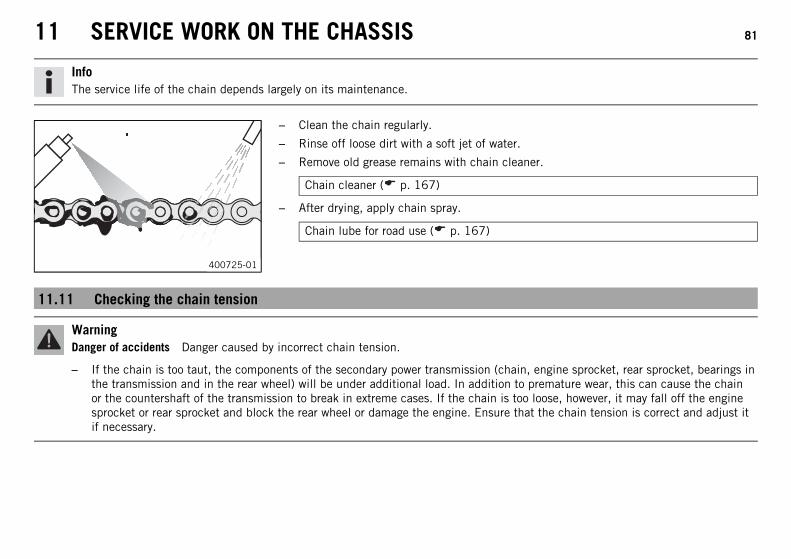
InfoThe service life of the chain depends largely on its maintenance.
400725-01
– Clean the chain regularly.
– Rinse off loose dirt with a soft jet of water.
– Remove old grease remains with chain cleaner.
Chain cleaner ( p. 167)
– After drying, apply chain spray.
Chain lube for road use ( p. 167)
11.11 Checking the chain tension
WarningDanger of accidents Danger caused by incorrect chain tension.
– If the chain is too taut, the components of the secondary power transmission (chain, engine sprocket, rear sprocket, bearings inthe transmission and in the rear wheel) will be under additional load. In addition to premature wear, this can cause the chainor the countershaft of the transmission to break in extreme cases. If the chain is too loose, however, it may fall off the enginesprocket or rear sprocket and block the rear wheel or damage the engine. Ensure that the chain tension is correct and adjust itif necessary.
11 SERVICE WORK ON THE CHASSIS 82
B00731-10
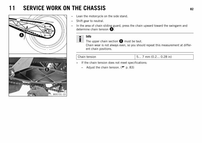
– Lean the motorcycle on the side stand.
– Shift gear to neutral.
– In the area of chain sliding guard, press the chain upward toward the swingarm anddetermine chain tension.
InfoThe upper chain section must be taut.Chain wear is not always even, so you should repeat this measurement at differ-ent chain positions.
Chain tension 5… 7 mm (0.2… 0.28 in)
» If the chain tension does not meet specifications:
– Adjust the chain tension. ( p. 83)
11 SERVICE WORK ON THE CHASSIS 83
11.12 Adjusting the chain tension
WarningDanger of accidents Danger caused by incorrect chain tension.
– If the chain is too taut, the components of the secondary power transmission (chain, engine sprocket, rear sprocket, bearings inthe transmission and in the rear wheel) will be under additional load. In addition to premature wear, this can cause the chainor the countershaft of the transmission to break in extreme cases. If the chain is too loose, however, it may fall off the enginesprocket or rear sprocket and block the rear wheel or damage the engine. Ensure that the chain tension is correct and adjust itif necessary.
Preparatory work– Check the chain tension. ( p. 81)
– Raise the motorcycle with the rear wheel stand. ( p. 74)
11 SERVICE WORK ON THE CHASSIS 84
B01606-12
Main work(Option: Without ABS)
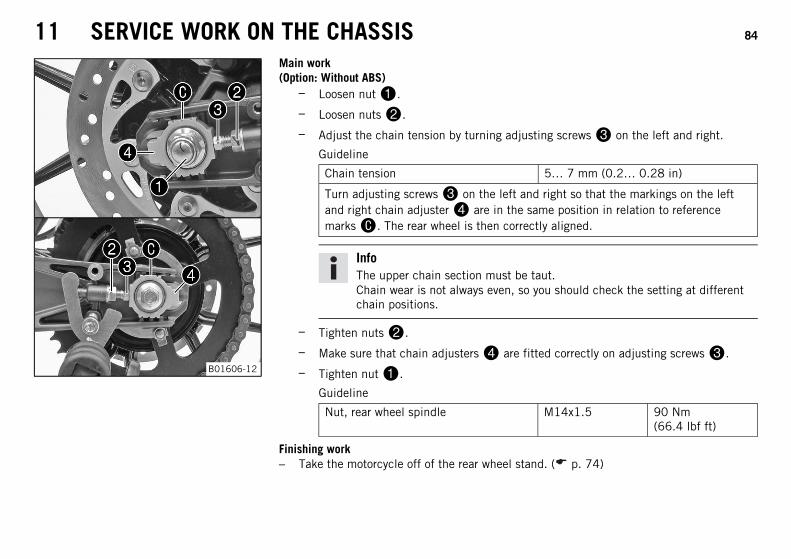
– Loosen nut.
– Loosen nuts.
– Adjust the chain tension by turning adjusting screws on the left and right.
Guideline
Chain tension 5… 7 mm (0.2… 0.28 in)
Turn adjusting screws on the left and right so that the markings on the leftand right chain adjuster are in the same position in relation to referencemarks. The rear wheel is then correctly aligned.
InfoThe upper chain section must be taut.Chain wear is not always even, so you should check the setting at differentchain positions.
– Tighten nuts.
– Make sure that chain adjusters are fitted correctly on adjusting screws.
– Tighten nut.
Guideline
Nut, rear wheel spindle M14x1.5 90 Nm(66.4 lbf ft)
Finishing work– Take the motorcycle off of the rear wheel stand. ( p. 74)
11 SERVICE WORK ON THE CHASSIS 85
11.13 Checking the chain, rear sprocket, and engine sprocket
100132-10
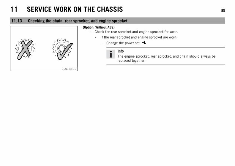
(Option: Without ABS)– Check the rear sprocket and engine sprocket for wear.
» If the rear sprocket and engine sprocket are worn:
– Change the power set.x
InfoThe engine sprocket, rear sprocket, and chain should always bereplaced together.
11 SERVICE WORK ON THE CHASSIS 86
1 2 3 18 19 20
000BB
00AA
401288-10
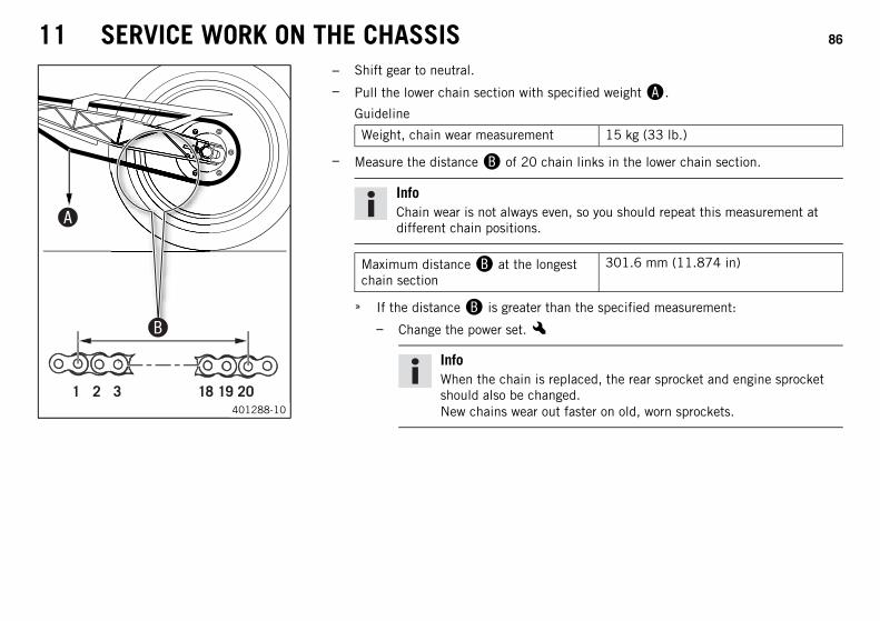
– Shift gear to neutral.
– Pull the lower chain section with specified weight.
Guideline
Weight, chain wear measurement 15 kg (33 lb.)
– Measure the distance of 20 chain links in the lower chain section.
InfoChain wear is not always even, so you should repeat this measurement atdifferent chain positions.
Maximum distance at the longestchain section
301.6 mm (11.874 in)
» If the distance is greater than the specified measurement:
– Change the power set.x
InfoWhen the chain is replaced, the rear sprocket and engine sprocketshould also be changed.New chains wear out faster on old, worn sprockets.
11 SERVICE WORK ON THE CHASSIS 87
C00198-10
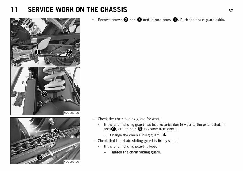
– Remove screws and and release screw. Push the chain guard aside.
C00199-10
– Check the chain sliding guard for wear.
» If the chain sliding guard has lost material due to wear to the extent that, inarea, drilled hole is visible from above:
– Change the chain sliding guard.x– Check that the chain sliding guard is firmly seated.
» If the chain sliding guard is loose:
– Tighten the chain sliding guard.
11 SERVICE WORK ON THE CHASSIS 88
C00198-10
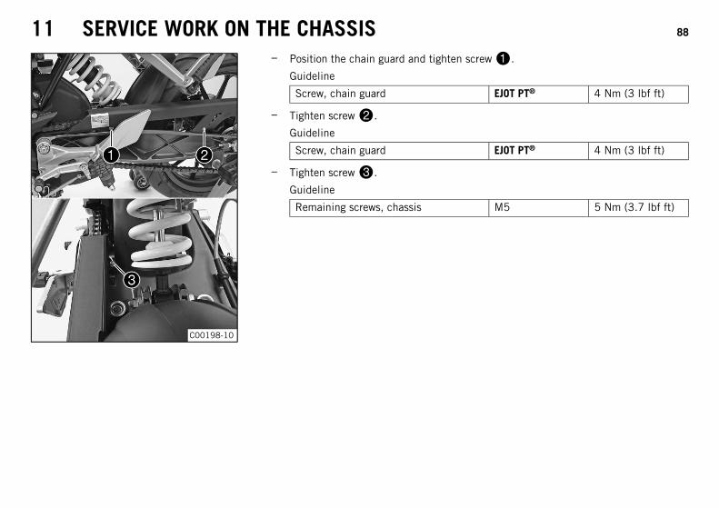
– Position the chain guard and tighten screw.
Guideline
Screw, chain guard EJOT PT® 4 Nm (3 lbf ft)
– Tighten screw.
Guideline
Screw, chain guard EJOT PT® 4 Nm (3 lbf ft)
– Tighten screw.
Guideline
Remaining screws, chassis M5 5 Nm (3.7 lbf ft)
11 SERVICE WORK ON THE CHASSIS 89
11.14 Removing the front spoiler
B00770-10
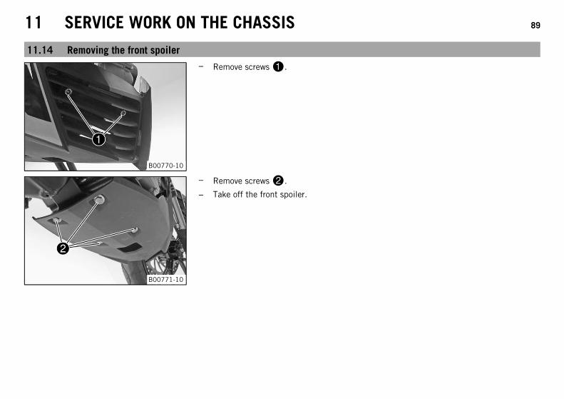
– Remove screws.
B00771-10
– Remove screws.
– Take off the front spoiler.
11 SERVICE WORK ON THE CHASSIS 90
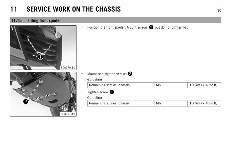
11.15 Fitting front spoiler
B00770-10
– Position the front spoiler. Mount screws but do not tighten yet.
B00771-10
– Mount and tighten screws.
Guideline
Remaining screws, chassis M6 10 Nm (7.4 lbf ft)
– Tighten screw.
Guideline
Remaining screws, chassis M6 10 Nm (7.4 lbf ft)
12 BRAKE SYSTEM 91
12.1 Checking the brake discs
WarningDanger of accidents Reduced braking efficiency due to worn brake disc(s).
– Change the worn brake disc(s) without delay. (Your authorized KTM workshop will be glad to help.)
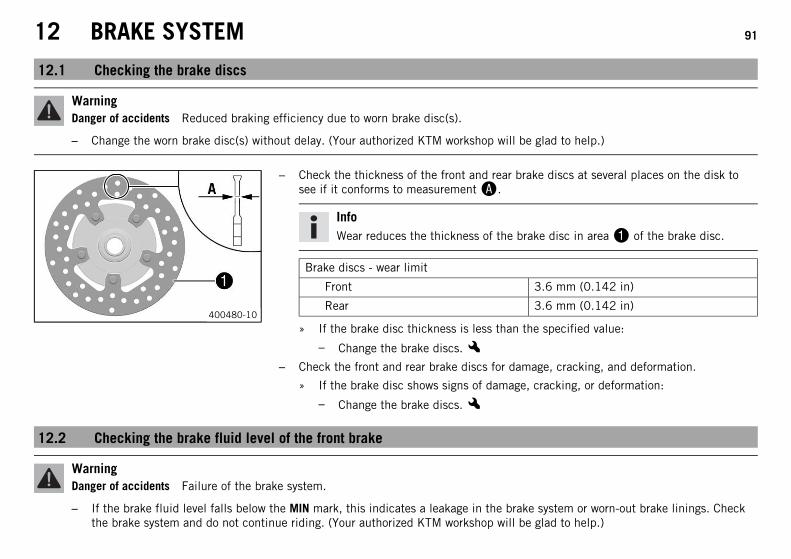
400480-10
– Check the thickness of the front and rear brake discs at several places on the disk tosee if it conforms to measurement.
InfoWear reduces the thickness of the brake disc in area of the brake disc.
Brake discs - wear limit
Front 3.6 mm (0.142 in)
Rear 3.6 mm (0.142 in)
» If the brake disc thickness is less than the specified value:
– Change the brake discs.x– Check the front and rear brake discs for damage, cracking, and deformation.
» If the brake disc shows signs of damage, cracking, or deformation:
– Change the brake discs.x
12.2 Checking the brake fluid level of the front brake
WarningDanger of accidents Failure of the brake system.
– If the brake fluid level falls below the MIN mark, this indicates a leakage in the brake system or worn-out brake linings. Checkthe brake system and do not continue riding. (Your authorized KTM workshop will be glad to help.)
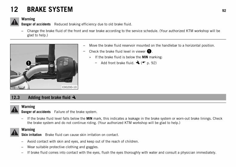
12 BRAKE SYSTEM 92
WarningDanger of accidents Reduced braking efficiency due to old brake fluid.
– Change the brake fluid of the front and rear brake according to the service schedule. (Your authorized KTM workshop will beglad to help.)
C00200-10
– Move the brake fluid reservoir mounted on the handlebar to a horizontal position.
– Check the brake fluid level in viewer.
» If the brake fluid is below the MIN marking:
– Add front brake fluid.x ( p. 92)
12.3 Adding front brake fluidx
WarningDanger of accidents Failure of the brake system.
– If the brake fluid level falls below the MIN mark, this indicates a leakage in the brake system or worn-out brake linings. Checkthe brake system and do not continue riding. (Your authorized KTM workshop will be glad to help.)
WarningSkin irritation Brake fluid can cause skin irritation on contact.
– Avoid contact with skin and eyes, and keep out of the reach of children.
– Wear suitable protective clothing and goggles.
– If brake fluid comes into contact with the eyes, flush the eyes thoroughly with water and consult a physician immediately.
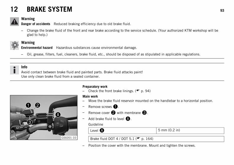
12 BRAKE SYSTEM 93
WarningDanger of accidents Reduced braking efficiency due to old brake fluid.
– Change the brake fluid of the front and rear brake according to the service schedule. (Your authorized KTM workshop will beglad to help.)
WarningEnvironmental hazard Hazardous substances cause environmental damage.
– Oil, grease, filters, fuel, cleaners, brake fluid, etc., should be disposed of as stipulated in applicable regulations.
InfoAvoid contact between brake fluid and painted parts. Brake fluid attacks paint!Use only clean brake fluid from a sealed container.
Preparatory work– Check the front brake linings. ( p. 94)
C00201-10
Main work– Move the brake fluid reservoir mounted on the handlebar to a horizontal position.
– Remove screws.
– Remove cover with membrane.
– Add brake fluid to level.
Guideline
Level 5 mm (0.2 in)
Brake fluid DOT 4 / DOT 5.1 ( p. 164)
– Position the cover with the membrane. Mount and tighten the screws.
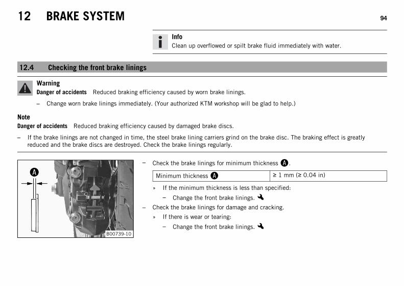
12 BRAKE SYSTEM 94
InfoClean up overflowed or spilt brake fluid immediately with water.
12.4 Checking the front brake linings
WarningDanger of accidents Reduced braking efficiency caused by worn brake linings.
– Change worn brake linings immediately. (Your authorized KTM workshop will be glad to help.)
NoteDanger of accidents Reduced braking efficiency caused by damaged brake discs.
– If the brake linings are not changed in time, the steel brake lining carriers grind on the brake disc. The braking effect is greatlyreduced and the brake discs are destroyed. Check the brake linings regularly.
B00739-10
– Check the brake linings for minimum thickness.
Minimum thickness ≥ 1 mm (≥ 0.04 in)
» If the minimum thickness is less than specified:
– Change the front brake linings.x– Check the brake linings for damage and cracking.
» If there is wear or tearing:
– Change the front brake linings.x
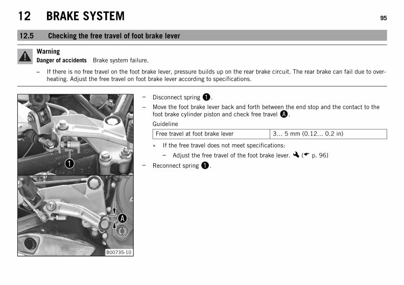
12 BRAKE SYSTEM 95
12.5 Checking the free travel of foot brake lever
WarningDanger of accidents Brake system failure.
– If there is no free travel on the foot brake lever, pressure builds up on the rear brake circuit. The rear brake can fail due to over-heating. Adjust the free travel on foot brake lever according to specifications.
B00735-10
– Disconnect spring.
– Move the foot brake lever back and forth between the end stop and the contact to thefoot brake cylinder piston and check free travel.
Guideline
Free travel at foot brake lever 3… 5 mm (0.12… 0.2 in)
» If the free travel does not meet specifications:
– Adjust the free travel of the foot brake lever.x ( p. 96)
– Reconnect spring.
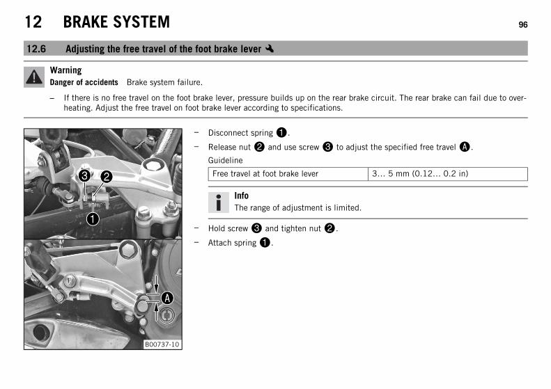
12 BRAKE SYSTEM 96
12.6 Adjusting the free travel of the foot brake leverx
WarningDanger of accidents Brake system failure.
– If there is no free travel on the foot brake lever, pressure builds up on the rear brake circuit. The rear brake can fail due to over-heating. Adjust the free travel on foot brake lever according to specifications.
B00737-10
– Disconnect spring.
– Release nut and use screw to adjust the specified free travel.
Guideline
Free travel at foot brake lever 3… 5 mm (0.12… 0.2 in)
InfoThe range of adjustment is limited.
– Hold screw and tighten nut.
– Attach spring.
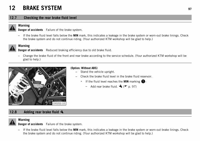
12 BRAKE SYSTEM 97
12.7 Checking the rear brake fluid level
WarningDanger of accidents Failure of the brake system.
– If the brake fluid level falls below the MIN mark, this indicates a leakage in the brake system or worn-out brake linings. Checkthe brake system and do not continue riding. (Your authorized KTM workshop will be glad to help.)
WarningDanger of accidents Reduced braking efficiency due to old brake fluid.
– Change the brake fluid of the front and rear brake according to the service schedule. (Your authorized KTM workshop will beglad to help.)
C00202-10
(Option: Without ABS)– Stand the vehicle upright.
– Check the brake fluid level in the brake fluid reservoir.
» If the fluid level reaches the MIN marking:
– Add rear brake fluid.x ( p. 97)
12.8 Adding rear brake fluidx
WarningDanger of accidents Failure of the brake system.
– If the brake fluid level falls below the MIN mark, this indicates a leakage in the brake system or worn-out brake linings. Checkthe brake system and do not continue riding. (Your authorized KTM workshop will be glad to help.)
12 BRAKE SYSTEM 98
WarningSkin irritation Brake fluid can cause skin irritation on contact.
– Avoid contact with skin and eyes, and keep out of the reach of children.
– Wear suitable protective clothing and goggles.
– If brake fluid comes into contact with the eyes, flush the eyes thoroughly with water and consult a physician immediately.
WarningDanger of accidents Reduced braking efficiency due to old brake fluid.
– Change the brake fluid of the front and rear brake according to the service schedule. (Your authorized KTM workshop will beglad to help.)
WarningEnvironmental hazard Hazardous substances cause environmental damage.
– Oil, grease, filters, fuel, cleaners, brake fluid, etc., should be disposed of as stipulated in applicable regulations.
InfoAvoid contact between brake fluid and painted parts. Brake fluid attacks paint!Use only clean brake fluid from a sealed container.
Preparatory work– Check the rear brake linings. ( p. 99)
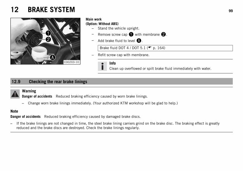
12 BRAKE SYSTEM 99
C00203-10
Main work(Option: Without ABS)
– Stand the vehicle upright.
– Remove screw cap with membrane.
– Add brake fluid to level.
Brake fluid DOT 4 / DOT 5.1 ( p. 164)
– Refit screw cap with membrane.
InfoClean up overflowed or spilt brake fluid immediately with water.
12.9 Checking the rear brake linings
WarningDanger of accidents Reduced braking efficiency caused by worn brake linings.
– Change worn brake linings immediately. (Your authorized KTM workshop will be glad to help.)
NoteDanger of accidents Reduced braking efficiency caused by damaged brake discs.
– If the brake linings are not changed in time, the steel brake lining carriers grind on the brake disc. The braking effect is greatlyreduced and the brake discs are destroyed. Check the brake linings regularly.
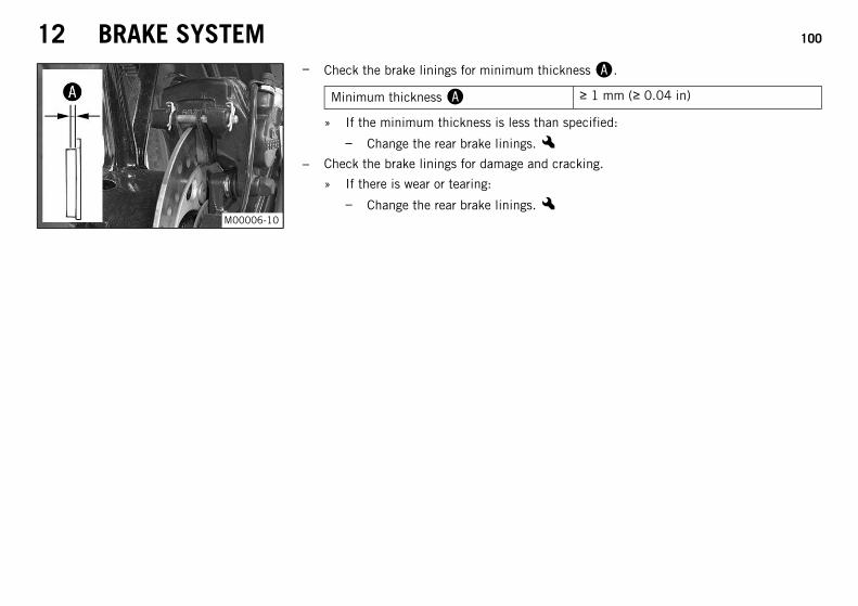
12 BRAKE SYSTEM 100
M00006-10
– Check the brake linings for minimum thickness.
Minimum thickness ≥ 1 mm (≥ 0.04 in)
» If the minimum thickness is less than specified:
– Change the rear brake linings.x– Check the brake linings for damage and cracking.
» If there is wear or tearing:
– Change the rear brake linings.x
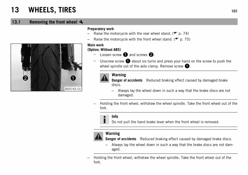
13 WHEELS, TIRES 101
13.1 Removing the front wheelxPreparatory work– Raise the motorcycle with the rear wheel stand. ( p. 74)
– Raise the motorcycle with the front wheel stand. ( p. 75)
B00743-10
Main work(Option: Without ABS)
– Loosen screw and screws.
– Unscrew screw about six turns and press your hand on the screw to push thewheel spindle out of the axle clamp. Remove screw.
WarningDanger of accidents Reduced braking effect caused by damaged brakediscs.
– Always lay the wheel down in such a way that the brake discs are notdamaged.
– Holding the front wheel, withdraw the wheel spindle. Take the front wheel out of thefork.
InfoDo not pull the hand brake lever when the front wheel is removed.
WarningDanger of accidents Reduced braking effect caused by damaged brake discs.
– Always lay the wheel down in such a way that the brake discs are not dam-aged.
– Holding the front wheel, withdraw the wheel spindle. Take the front wheel out of thefork.
13 WHEELS, TIRES 102
InfoDo not pull the hand brake lever when the front wheel is removed.
13.2 Installing the front wheelx
WarningDanger of accidents Reduced braking efficiency due to oil or grease on the brake discs.
– Always keep the brake discs free of oil and grease, and clean them with brake cleaner when necessary.
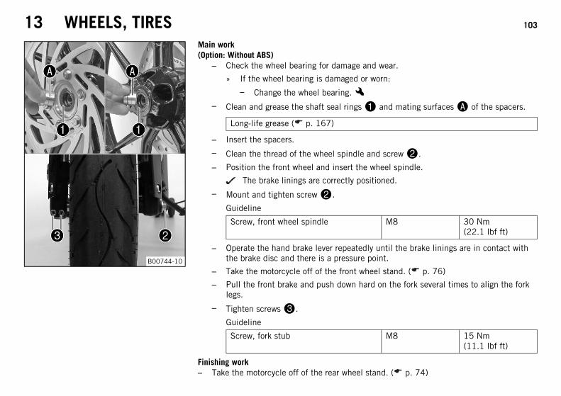
13 WHEELS, TIRES 103
B00744-10
Main work(Option: Without ABS)
– Check the wheel bearing for damage and wear.
» If the wheel bearing is damaged or worn:
– Change the wheel bearing.x– Clean and grease the shaft seal rings and mating surfaces of the spacers.
Long-life grease ( p. 167)
– Insert the spacers.
– Clean the thread of the wheel spindle and screw.
– Position the front wheel and insert the wheel spindle.
The brake linings are correctly positioned.
– Mount and tighten screw.
Guideline
Screw, front wheel spindle M8 30 Nm(22.1 lbf ft)
– Operate the hand brake lever repeatedly until the brake linings are in contact withthe brake disc and there is a pressure point.
– Take the motorcycle off of the front wheel stand. ( p. 76)
– Pull the front brake and push down hard on the fork several times to align the forklegs.
– Tighten screws.
Guideline
Screw, fork stub M8 15 Nm(11.1 lbf ft)
Finishing work– Take the motorcycle off of the rear wheel stand. ( p. 74)
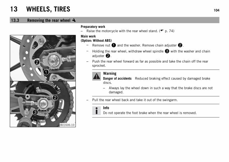
13 WHEELS, TIRES 104
13.3 Removing the rear wheelxPreparatory work– Raise the motorcycle with the rear wheel stand. ( p. 74)
B01606-10
Main work(Option: Without ABS)
– Remove nut and the washer. Remove chain adjuster.
– Holding the rear wheel, withdraw wheel spindle with the washer and chainadjuster.
– Push the rear wheel forward as far as possible and take the chain off the rearsprocket.
WarningDanger of accidents Reduced braking effect caused by damaged brakediscs.
– Always lay the wheel down in such a way that the brake discs are notdamaged.
– Pull the rear wheel back and take it out of the swingarm.
InfoDo not operate the foot brake when the rear wheel is removed.
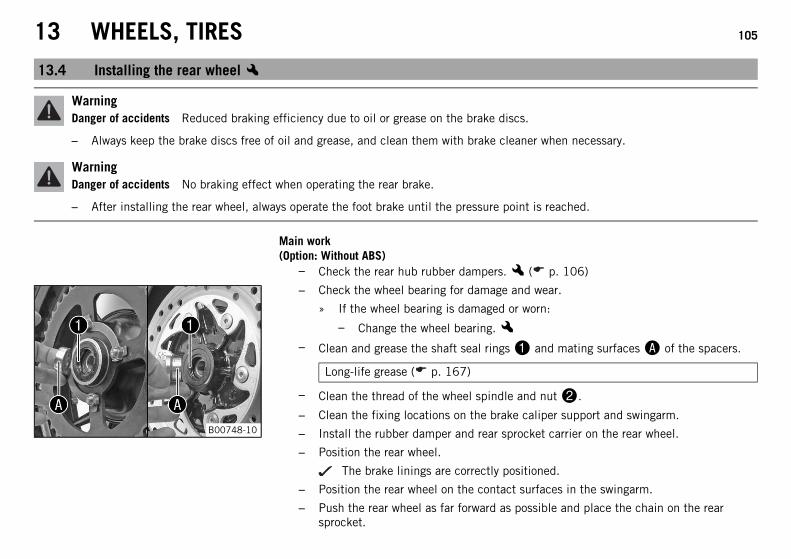
13 WHEELS, TIRES 105
13.4 Installing the rear wheelx
WarningDanger of accidents Reduced braking efficiency due to oil or grease on the brake discs.
– Always keep the brake discs free of oil and grease, and clean them with brake cleaner when necessary.
WarningDanger of accidents No braking effect when operating the rear brake.
– After installing the rear wheel, always operate the foot brake until the pressure point is reached.
Main work(Option: Without ABS)
– Check the rear hub rubber dampers.x ( p. 106)
B00748-10
– Check the wheel bearing for damage and wear.
» If the wheel bearing is damaged or worn:
– Change the wheel bearing.x– Clean and grease the shaft seal rings and mating surfaces of the spacers.
Long-life grease ( p. 167)
– Clean the thread of the wheel spindle and nut.
– Clean the fixing locations on the brake caliper support and swingarm.
– Install the rubber damper and rear sprocket carrier on the rear wheel.
– Position the rear wheel.
The brake linings are correctly positioned.
– Position the rear wheel on the contact surfaces in the swingarm.
– Push the rear wheel as far forward as possible and place the chain on the rearsprocket.
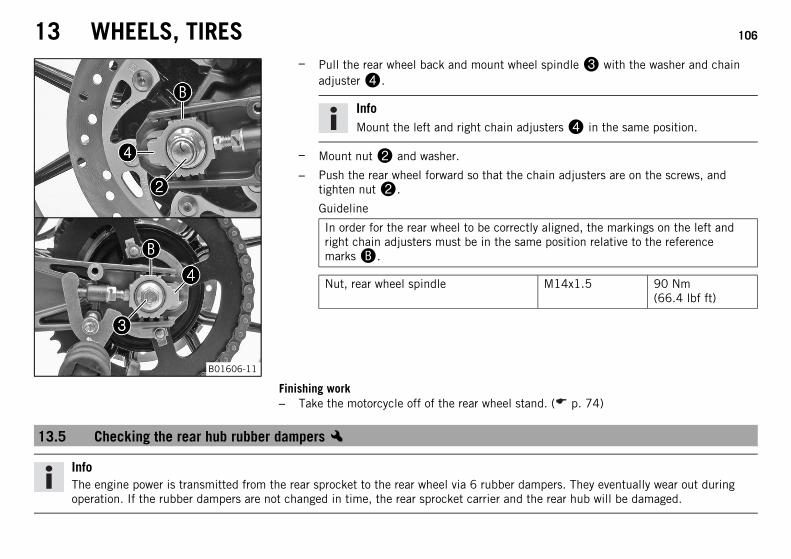
13 WHEELS, TIRES 106
B01606-11
– Pull the rear wheel back and mount wheel spindle with the washer and chainadjuster.
InfoMount the left and right chain adjusters in the same position.
– Mount nut and washer.
– Push the rear wheel forward so that the chain adjusters are on the screws, andtighten nut.
Guideline
In order for the rear wheel to be correctly aligned, the markings on the left andright chain adjusters must be in the same position relative to the referencemarks.
Nut, rear wheel spindle M14x1.5 90 Nm(66.4 lbf ft)
Finishing work– Take the motorcycle off of the rear wheel stand. ( p. 74)
13.5 Checking the rear hub rubber dampersx
InfoThe engine power is transmitted from the rear sprocket to the rear wheel via 6 rubber dampers. They eventually wear out duringoperation. If the rubber dampers are not changed in time, the rear sprocket carrier and the rear hub will be damaged.
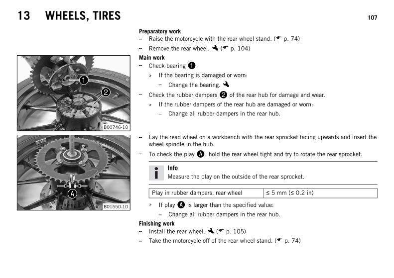
13 WHEELS, TIRES 107
Preparatory work– Raise the motorcycle with the rear wheel stand. ( p. 74)
– Remove the rear wheel.x ( p. 104)
B00746-10
Main work– Check bearing.
» If the bearing is damaged or worn:
– Change the bearing.x– Check the rubber dampers of the rear hub for damage and wear.
» If the rubber dampers of the rear hub are damaged or worn:
– Change all rubber dampers in the rear hub.
B01550-10
– Lay the read wheel on a workbench with the rear sprocket facing upwards and insert thewheel spindle in the hub.
– To check the play, hold the rear wheel tight and try to rotate the rear sprocket.
InfoMeasure the play on the outside of the rear sprocket.
Play in rubber dampers, rear wheel ≤ 5 mm (≤ 0.2 in)
» If play is larger than the specified value:
– Change all rubber dampers in the rear hub.
Finishing work– Install the rear wheel.x ( p. 105)
– Take the motorcycle off of the rear wheel stand. ( p. 74)
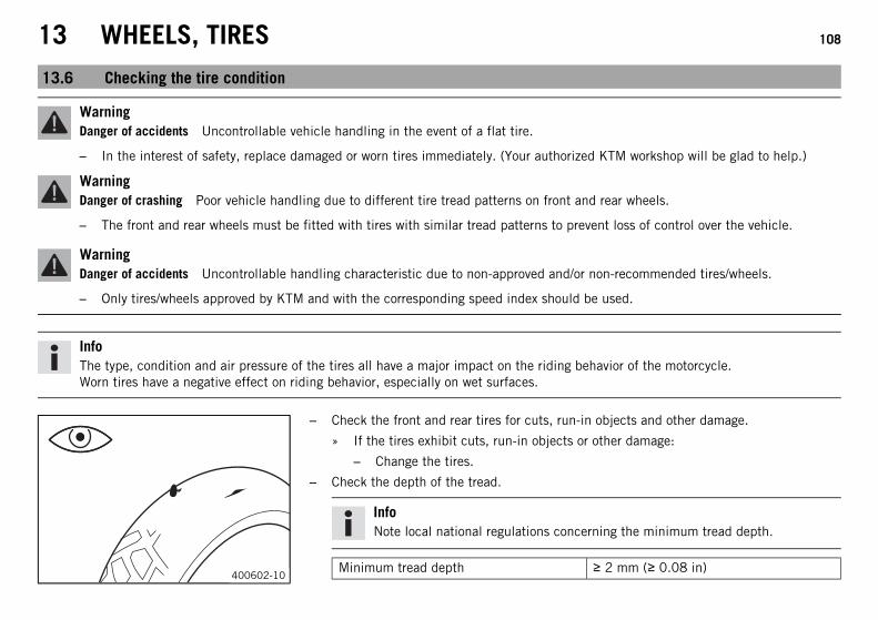
13 WHEELS, TIRES 108
13.6 Checking the tire condition
WarningDanger of accidents Uncontrollable vehicle handling in the event of a flat tire.
– In the interest of safety, replace damaged or worn tires immediately. (Your authorized KTM workshop will be glad to help.)
WarningDanger of crashing Poor vehicle handling due to different tire tread patterns on front and rear wheels.
– The front and rear wheels must be fitted with tires with similar tread patterns to prevent loss of control over the vehicle.
WarningDanger of accidents Uncontrollable handling characteristic due to non-approved and/or non-recommended tires/wheels.
– Only tires/wheels approved by KTM and with the corresponding speed index should be used.
InfoThe type, condition and air pressure of the tires all have a major impact on the riding behavior of the motorcycle.Worn tires have a negative effect on riding behavior, especially on wet surfaces.
400602-10
– Check the front and rear tires for cuts, run-in objects and other damage.
» If the tires exhibit cuts, run-in objects or other damage:
– Change the tires.
– Check the depth of the tread.
InfoNote local national regulations concerning the minimum tread depth.
Minimum tread depth ≥ 2 mm (≥ 0.08 in)
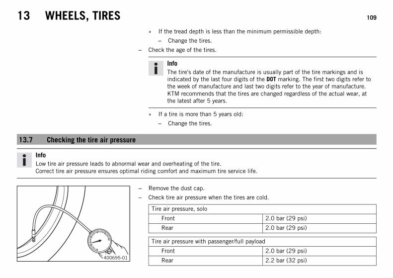
13 WHEELS, TIRES 109
» If the tread depth is less than the minimum permissible depth:
– Change the tires.
– Check the age of the tires.
InfoThe tire's date of the manufacture is usually part of the tire markings and isindicated by the last four digits of the DOT marking. The first two digits refer tothe week of manufacture and last two digits refer to the year of manufacture.KTM recommends that the tires are changed regardless of the actual wear, atthe latest after 5 years.
» If a tire is more than 5 years old:
– Change the tires.
13.7 Checking the tire air pressure
InfoLow tire air pressure leads to abnormal wear and overheating of the tire.Correct tire air pressure ensures optimal riding comfort and maximum tire service life.
400695-01
– Remove the dust cap.
– Check tire air pressure when the tires are cold.
Tire air pressure, solo
Front 2.0 bar (29 psi)
Rear 2.0 bar (29 psi)
Tire air pressure with passenger/full payload
Front 2.0 bar (29 psi)
Rear 2.2 bar (32 psi)
13 WHEELS, TIRES 110
» If the tire air pressure does not meet specifications:
– Correct the tire air pressure.
– Mount the dust cap.
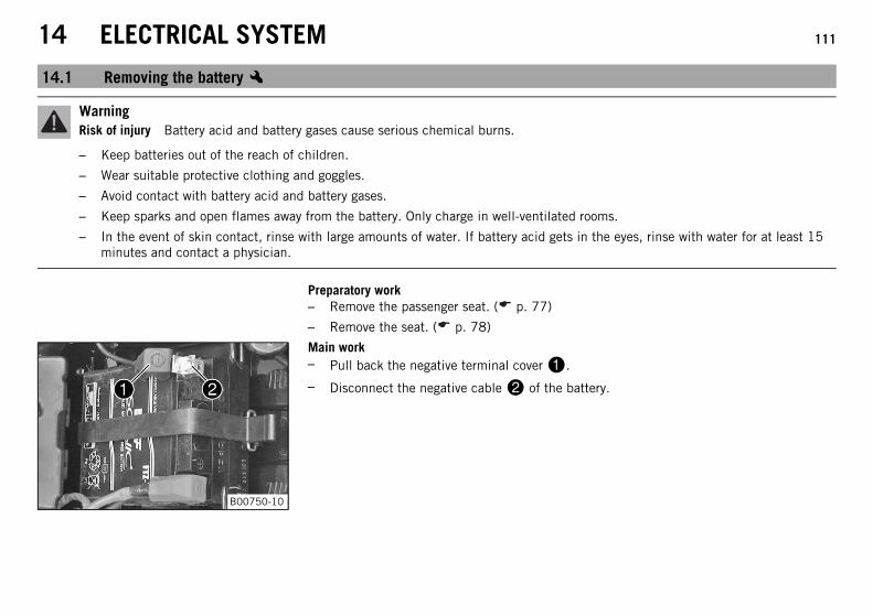
14 ELECTRICAL SYSTEM 111
14.1 Removing the batteryx
WarningRisk of injury Battery acid and battery gases cause serious chemical burns.
– Keep batteries out of the reach of children.
– Wear suitable protective clothing and goggles.
– Avoid contact with battery acid and battery gases.
– Keep sparks and open flames away from the battery. Only charge in well-ventilated rooms.
– In the event of skin contact, rinse with large amounts of water. If battery acid gets in the eyes, rinse with water for at least 15minutes and contact a physician.
Preparatory work– Remove the passenger seat. ( p. 77)
– Remove the seat. ( p. 78)
B00750-10
Main work– Pull back the negative terminal cover.
– Disconnect the negative cable of the battery.
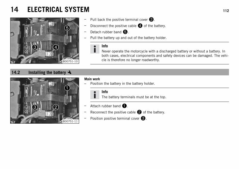
14 ELECTRICAL SYSTEM 112
B00751-10
– Pull back the positive terminal cover.
– Disconnect the positive cable of the battery.
– Detach rubber band.
– Pull the battery up and out of the battery holder.
InfoNever operate the motorcycle with a discharged battery or without a battery. Inboth cases, electrical components and safety devices can be damaged. The vehi-cle is therefore no longer roadworthy.
14.2 Installing the batteryx
B00751-11
Main work– Position the battery in the battery holder.
InfoThe battery terminals must be at the top.
– Attach rubber band.
– Reconnect the positive cable of the battery.
– Position positive terminal cover.
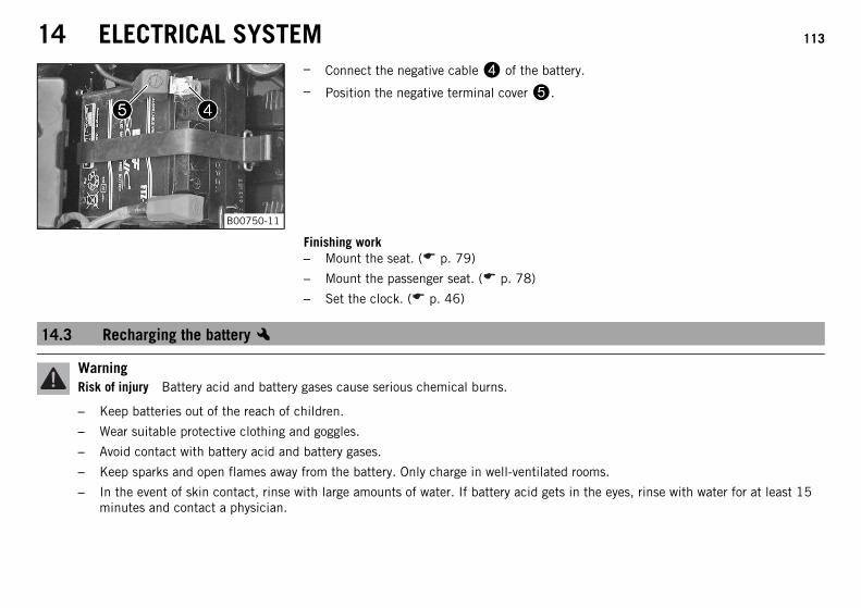
14 ELECTRICAL SYSTEM 113
B00750-11
– Connect the negative cable of the battery.
– Position the negative terminal cover.
Finishing work– Mount the seat. ( p. 79)
– Mount the passenger seat. ( p. 78)
– Set the clock. ( p. 46)
14.3 Recharging the batteryx
WarningRisk of injury Battery acid and battery gases cause serious chemical burns.
– Keep batteries out of the reach of children.
– Wear suitable protective clothing and goggles.
– Avoid contact with battery acid and battery gases.
– Keep sparks and open flames away from the battery. Only charge in well-ventilated rooms.
– In the event of skin contact, rinse with large amounts of water. If battery acid gets in the eyes, rinse with water for at least 15minutes and contact a physician.
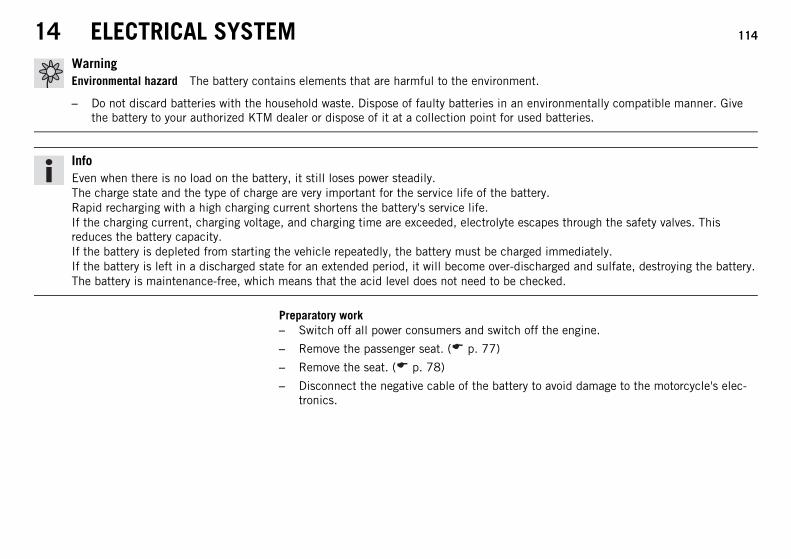
14 ELECTRICAL SYSTEM 114
WarningEnvironmental hazard The battery contains elements that are harmful to the environment.
– Do not discard batteries with the household waste. Dispose of faulty batteries in an environmentally compatible manner. Givethe battery to your authorized KTM dealer or dispose of it at a collection point for used batteries.
InfoEven when there is no load on the battery, it still loses power steadily.The charge state and the type of charge are very important for the service life of the battery.Rapid recharging with a high charging current shortens the battery's service life.If the charging current, charging voltage, and charging time are exceeded, electrolyte escapes through the safety valves. Thisreduces the battery capacity.If the battery is depleted from starting the vehicle repeatedly, the battery must be charged immediately.If the battery is left in a discharged state for an extended period, it will become over-discharged and sulfate, destroying the battery.The battery is maintenance-free, which means that the acid level does not need to be checked.
Preparatory work– Switch off all power consumers and switch off the engine.
– Remove the passenger seat. ( p. 77)
– Remove the seat. ( p. 78)
– Disconnect the negative cable of the battery to avoid damage to the motorcycle's elec-tronics.
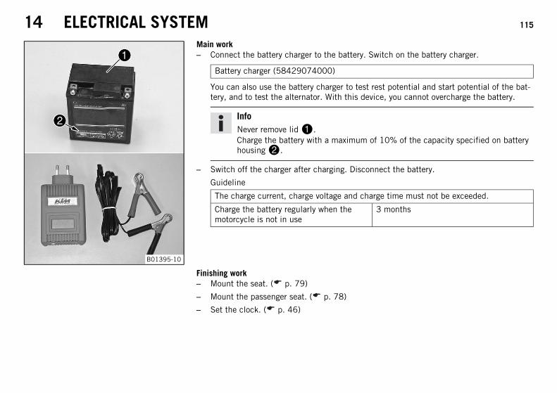
14 ELECTRICAL SYSTEM 115
B01395-10
Main work– Connect the battery charger to the battery. Switch on the battery charger.
Battery charger (58429074000)
You can also use the battery charger to test rest potential and start potential of the bat-tery, and to test the alternator. With this device, you cannot overcharge the battery.
InfoNever remove lid.Charge the battery with a maximum of 10% of the capacity specified on batteryhousing.
– Switch off the charger after charging. Disconnect the battery.
Guideline
The charge current, charge voltage and charge time must not be exceeded.
Charge the battery regularly when themotorcycle is not in use
3 months
Finishing work– Mount the seat. ( p. 79)
– Mount the passenger seat. ( p. 78)
– Set the clock. ( p. 46)
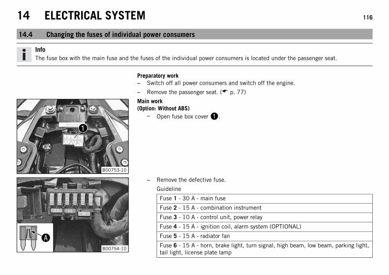
14 ELECTRICAL SYSTEM 116
14.4 Changing the fuses of individual power consumers
InfoThe fuse box with the main fuse and the fuses of the individual power consumers is located under the passenger seat.
Preparatory work– Switch off all power consumers and switch off the engine.
– Remove the passenger seat. ( p. 77)
B00753-10
Main work(Option: Without ABS)
– Open fuse box cover.
B00754-10
– Remove the defective fuse.
Guideline
Fuse 1 - 30 A - main fuse
Fuse 2 - 15 A - combination instrument
Fuse 3 - 10 A - control unit, power relay
Fuse 4 - 15 A - ignition coil, alarm system (OPTIONAL)
Fuse 5 - 15 A - radiator fan
Fuse 6 - 15 A - horn, brake light, turn signal, high beam, low beam, parking light,tail light, license plate lamp
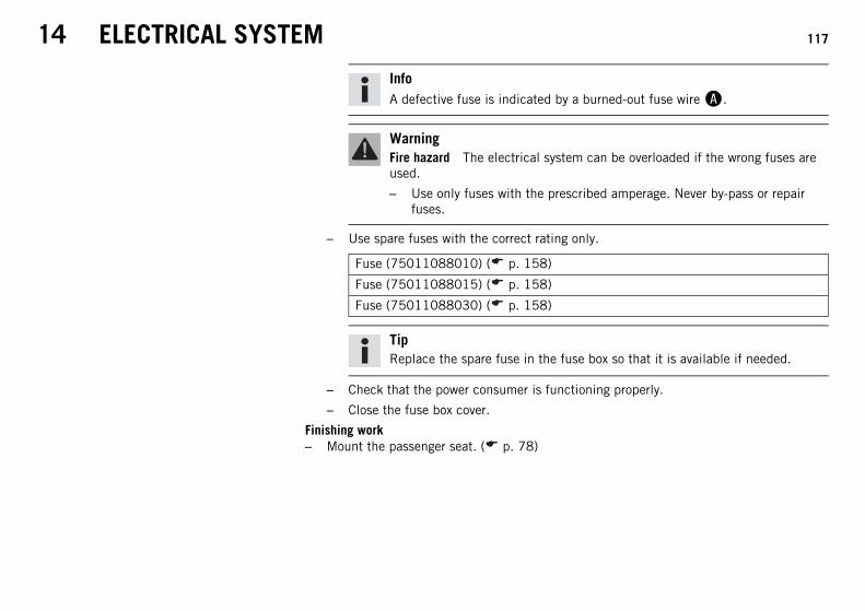
14 ELECTRICAL SYSTEM 117
InfoA defective fuse is indicated by a burned-out fuse wire.
WarningFire hazard The electrical system can be overloaded if the wrong fuses areused.
– Use only fuses with the prescribed amperage. Never by-pass or repairfuses.
– Use spare fuses with the correct rating only.
Fuse (75011088010) ( p. 158)
Fuse (75011088015) ( p. 158)
Fuse (75011088030) ( p. 158)
TipReplace the spare fuse in the fuse box so that it is available if needed.
– Check that the power consumer is functioning properly.
– Close the fuse box cover.
Finishing work– Mount the passenger seat. ( p. 78)
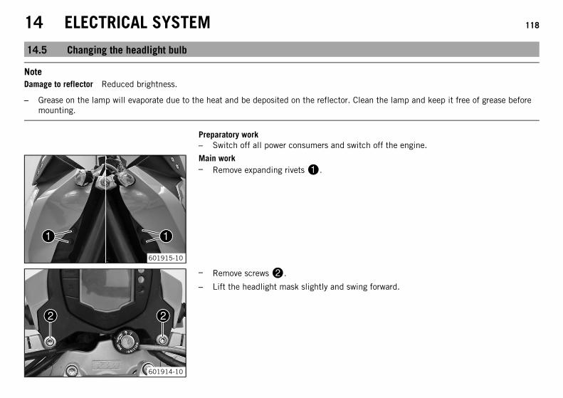
14 ELECTRICAL SYSTEM 118
14.5 Changing the headlight bulb
NoteDamage to reflector Reduced brightness.
– Grease on the lamp will evaporate due to the heat and be deposited on the reflector. Clean the lamp and keep it free of grease beforemounting.
Preparatory work– Switch off all power consumers and switch off the engine.
601915-10
Main work– Remove expanding rivets.
601914-10
– Remove screws.
– Lift the headlight mask slightly and swing forward.
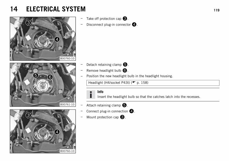
14 ELECTRICAL SYSTEM 119
B00760-10
– Take off protection cap.
– Disconnect plug-in connector.
B00761-10
– Detach retaining clamp.
– Remove headlight bulb.
– Position the new headlight bulb in the headlight housing.
Headlight (H4/socket P43t) ( p. 158)
InfoInsert the headlight bulb so that the catches latch into the recesses.
– Attach retaining clamp.
B00760-10
– Connect plug-in connection.
– Mount protection cap.
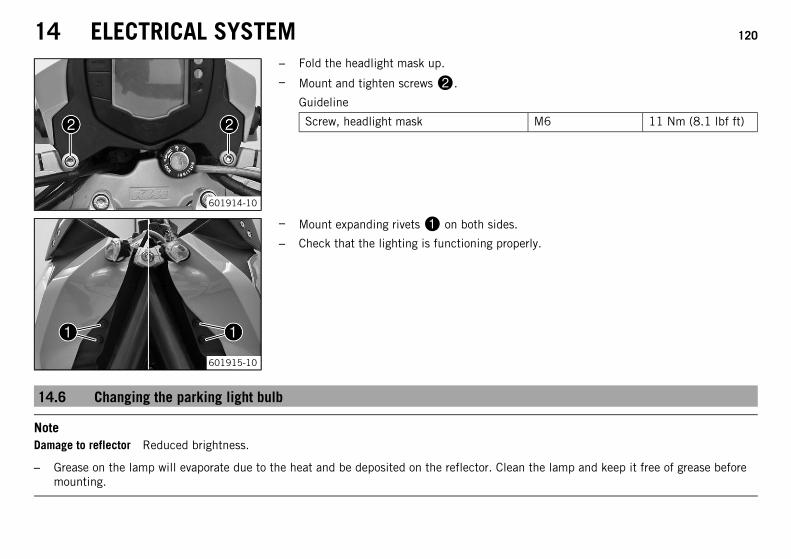
14 ELECTRICAL SYSTEM 120
601914-10
– Fold the headlight mask up.
– Mount and tighten screws.
Guideline
Screw, headlight mask M6 11 Nm (8.1 lbf ft)
601915-10
– Mount expanding rivets on both sides.
– Check that the lighting is functioning properly.
14.6 Changing the parking light bulb
NoteDamage to reflector Reduced brightness.
– Grease on the lamp will evaporate due to the heat and be deposited on the reflector. Clean the lamp and keep it free of grease beforemounting.
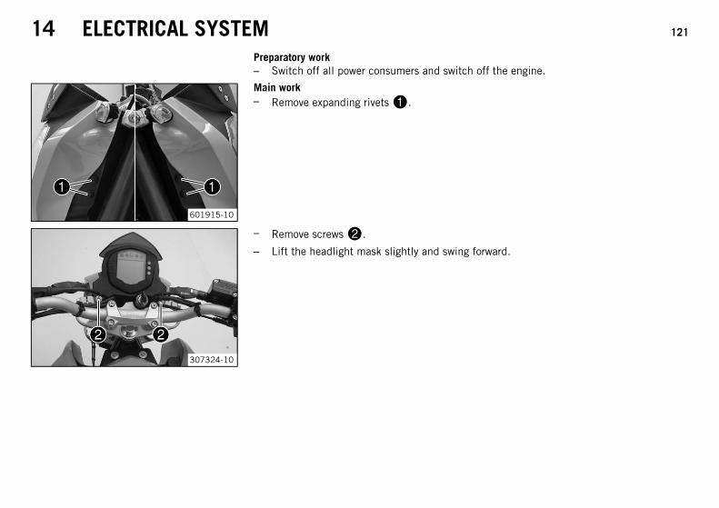
14 ELECTRICAL SYSTEM 121
Preparatory work– Switch off all power consumers and switch off the engine.
601915-10
Main work– Remove expanding rivets.
307324-10
– Remove screws.
– Lift the headlight mask slightly and swing forward.
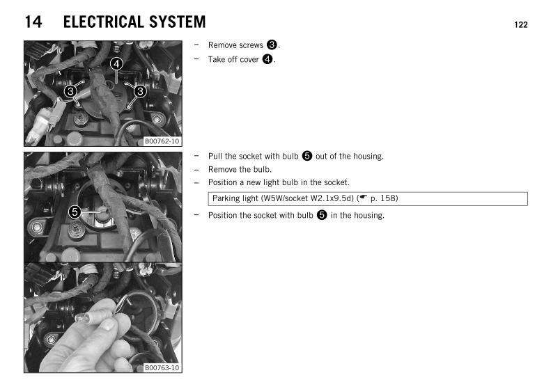
14 ELECTRICAL SYSTEM 122
B00762-10
– Remove screws.
– Take off cover.
B00763-10
– Pull the socket with bulb out of the housing.
– Remove the bulb.
– Position a new light bulb in the socket.
Parking light (W5W/socket W2.1x9.5d) ( p. 158)
– Position the socket with bulb in the housing.
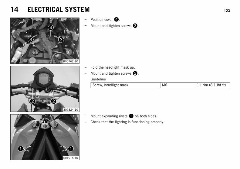
14 ELECTRICAL SYSTEM 123
B00762-10
– Position cover.
– Mount and tighten screws.
307324-10
– Fold the headlight mask up.
– Mount and tighten screws.
Guideline
Screw, headlight mask M6 11 Nm (8.1 lbf ft)
601915-10
– Mount expanding rivets on both sides.
– Check that the lighting is functioning properly.
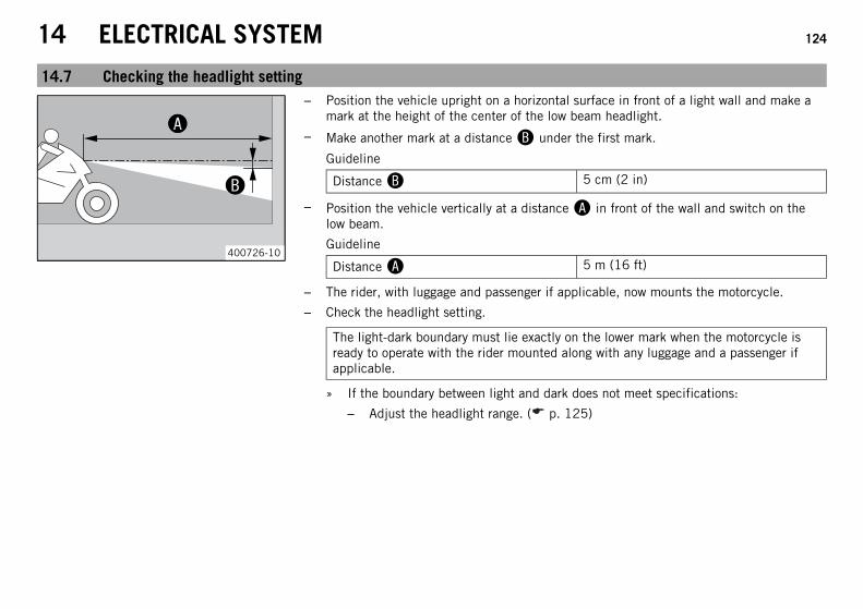
14 ELECTRICAL SYSTEM 124
14.7 Checking the headlight setting
00AA
00BB
400726-10
– Position the vehicle upright on a horizontal surface in front of a light wall and make amark at the height of the center of the low beam headlight.
– Make another mark at a distance under the first mark.
Guideline
Distance 5 cm (2 in)
– Position the vehicle vertically at a distance in front of the wall and switch on thelow beam.
Guideline
Distance 5 m (16 ft)
– The rider, with luggage and passenger if applicable, now mounts the motorcycle.
– Check the headlight setting.
The light-dark boundary must lie exactly on the lower mark when the motorcycle isready to operate with the rider mounted along with any luggage and a passenger ifapplicable.
» If the boundary between light and dark does not meet specifications:
– Adjust the headlight range. ( p. 125)
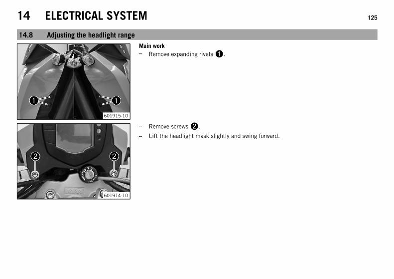
14 ELECTRICAL SYSTEM 125
14.8 Adjusting the headlight range
601915-10
Main work– Remove expanding rivets.
601914-10
– Remove screws.
– Lift the headlight mask slightly and swing forward.
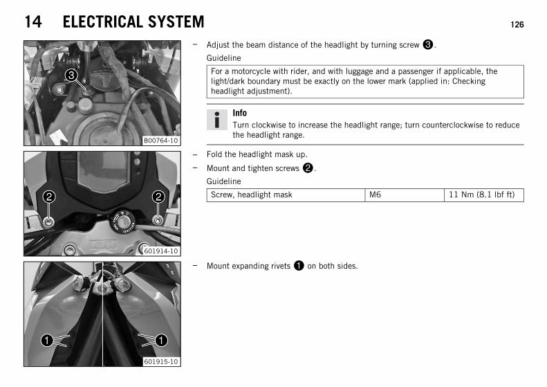
14 ELECTRICAL SYSTEM 126
B00764-10
– Adjust the beam distance of the headlight by turning screw.
Guideline
For a motorcycle with rider, and with luggage and a passenger if applicable, thelight/dark boundary must be exactly on the lower mark (applied in: Checkingheadlight adjustment).
InfoTurn clockwise to increase the headlight range; turn counterclockwise to reducethe headlight range.
601914-10
– Fold the headlight mask up.
– Mount and tighten screws.
Guideline
Screw, headlight mask M6 11 Nm (8.1 lbf ft)
601915-10
– Mount expanding rivets on both sides.
14 ELECTRICAL SYSTEM 127
Finishing work– Check the headlight setting. ( p. 124)
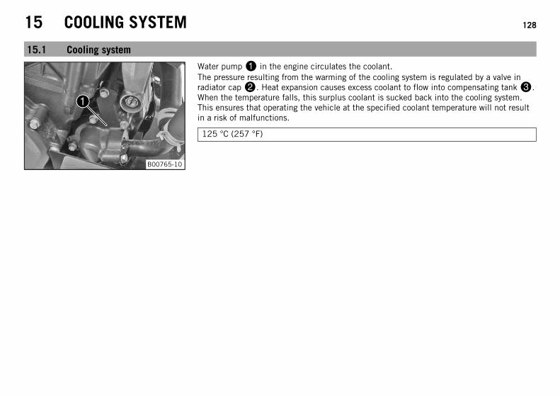
15 COOLING SYSTEM 128
15.1 Cooling system
B00765-10
Water pump in the engine circulates the coolant.The pressure resulting from the warming of the cooling system is regulated by a valve inradiator cap. Heat expansion causes excess coolant to flow into compensating tank.When the temperature falls, this surplus coolant is sucked back into the cooling system.This ensures that operating the vehicle at the specified coolant temperature will not resultin a risk of malfunctions.
125 °C (257 °F)
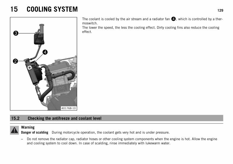
15 COOLING SYSTEM 129
401768-10
The coolant is cooled by the air stream and a radiator fan, which is controlled by a ther-moswitch.The lower the speed, the less the cooling effect. Dirty cooling fins also reduce the coolingeffect.
15.2 Checking the antifreeze and coolant level
WarningDanger of scalding During motorcycle operation, the coolant gets very hot and is under pressure.
– Do not remove the radiator cap, radiator hoses or other cooling system components when the engine is hot. Allow the engineand cooling system to cool down. In case of scalding, rinse immediately with lukewarm water.
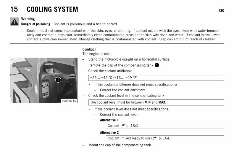
15 COOLING SYSTEM 130
WarningDanger of poisoning Coolant is poisonous and a health hazard.
– Coolant must not come into contact with the skin, eyes, or clothing. If contact occurs with the eyes, rinse with water immedi-ately and contact a physician. Immediately clean contaminated areas on the skin with soap and water. If coolant is swallowed,contact a physician immediately. Change clothing that is contaminated with coolant. Keep coolant out of reach of children.
ConditionThe engine is cold.
B00766-10
– Stand the motorcycle upright on a horizontal surface.
– Remove the cap of the compensating tank.
– Check the coolant antifreeze.
−25… −45 °C (−13… −49 °F)
» If the coolant antifreeze does not meet specifications:
– Correct the coolant antifreeze.
– Check the coolant level in the compensating tank.
The coolant level must be between MIN and MAX.
» If the coolant level does not meet specifications:
– Correct the coolant level.
Alternative 1
Coolant ( p. 164)
Alternative 2
Coolant (mixed ready to use) ( p. 164)
– Mount the cap of the compensating tank.
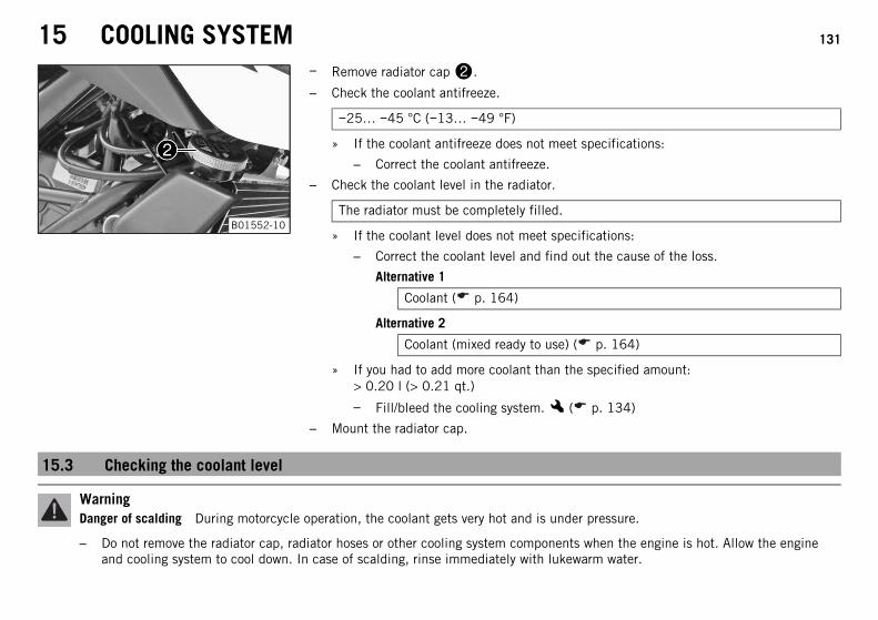
15 COOLING SYSTEM 131
B01552-10
– Remove radiator cap.
– Check the coolant antifreeze.
−25… −45 °C (−13… −49 °F)
» If the coolant antifreeze does not meet specifications:
– Correct the coolant antifreeze.
– Check the coolant level in the radiator.
The radiator must be completely filled.
» If the coolant level does not meet specifications:
– Correct the coolant level and find out the cause of the loss.
Alternative 1
Coolant ( p. 164)
Alternative 2
Coolant (mixed ready to use) ( p. 164)
» If you had to add more coolant than the specified amount:> 0.20 l (> 0.21 qt.)
– Fill/bleed the cooling system.x ( p. 134)
– Mount the radiator cap.
15.3 Checking the coolant level
WarningDanger of scalding During motorcycle operation, the coolant gets very hot and is under pressure.
– Do not remove the radiator cap, radiator hoses or other cooling system components when the engine is hot. Allow the engineand cooling system to cool down. In case of scalding, rinse immediately with lukewarm water.
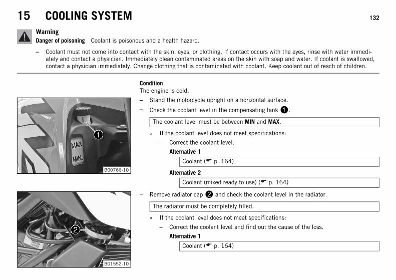
15 COOLING SYSTEM 132
WarningDanger of poisoning Coolant is poisonous and a health hazard.
– Coolant must not come into contact with the skin, eyes, or clothing. If contact occurs with the eyes, rinse with water immedi-ately and contact a physician. Immediately clean contaminated areas on the skin with soap and water. If coolant is swallowed,contact a physician immediately. Change clothing that is contaminated with coolant. Keep coolant out of reach of children.
ConditionThe engine is cold.
B00766-10
– Stand the motorcycle upright on a horizontal surface.
– Check the coolant level in the compensating tank.
The coolant level must be between MIN and MAX.
» If the coolant level does not meet specifications:
– Correct the coolant level.
Alternative 1
Coolant ( p. 164)
Alternative 2
Coolant (mixed ready to use) ( p. 164)
B01552-10
– Remove radiator cap and check the coolant level in the radiator.
The radiator must be completely filled.
» If the coolant level does not meet specifications:
– Correct the coolant level and find out the cause of the loss.
Alternative 1
Coolant ( p. 164)
15 COOLING SYSTEM 133
Alternative 2
Coolant (mixed ready to use) ( p. 164)
» If you had to add more coolant than the specified amount:> 0.20 l (> 0.21 qt.)
– Fill/bleed the cooling system.x ( p. 134)
– Mount the radiator cap.
15.4 Draining the coolantx
WarningDanger of scalding During motorcycle operation, the coolant gets very hot and is under pressure.
– Do not remove the radiator cap, radiator hoses or other cooling system components when the engine is hot. Allow the engineand cooling system to cool down. In case of scalding, rinse immediately with lukewarm water.
WarningDanger of poisoning Coolant is poisonous and a health hazard.
– Coolant must not come into contact with the skin, eyes, or clothing. If contact occurs with the eyes, rinse with water immedi-ately and contact a physician. Immediately clean contaminated areas on the skin with soap and water. If coolant is swallowed,contact a physician immediately. Change clothing that is contaminated with coolant. Keep coolant out of reach of children.
ConditionThe engine is cold.
Preparatory work– Remove the front spoiler. ( p. 89)
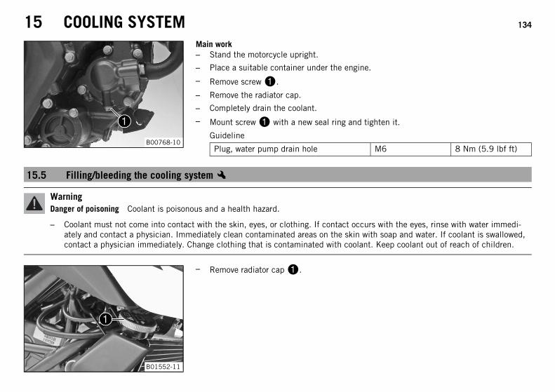
15 COOLING SYSTEM 134
B00768-10
Main work– Stand the motorcycle upright.
– Place a suitable container under the engine.
– Remove screw.
– Remove the radiator cap.
– Completely drain the coolant.
– Mount screw with a new seal ring and tighten it.
Guideline
Plug, water pump drain hole M6 8 Nm (5.9 lbf ft)
15.5 Filling/bleeding the cooling systemx
WarningDanger of poisoning Coolant is poisonous and a health hazard.
– Coolant must not come into contact with the skin, eyes, or clothing. If contact occurs with the eyes, rinse with water immedi-ately and contact a physician. Immediately clean contaminated areas on the skin with soap and water. If coolant is swallowed,contact a physician immediately. Change clothing that is contaminated with coolant. Keep coolant out of reach of children.
B01552-11
– Remove radiator cap.
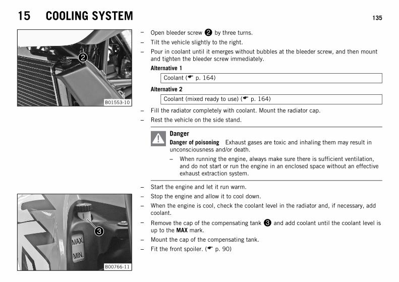
15 COOLING SYSTEM 135
B01553-10
– Open bleeder screw by three turns.
– Tilt the vehicle slightly to the right.
– Pour in coolant until it emerges without bubbles at the bleeder screw, and then mountand tighten the bleeder screw immediately.
Alternative 1
Coolant ( p. 164)
Alternative 2
Coolant (mixed ready to use) ( p. 164)
– Fill the radiator completely with coolant. Mount the radiator cap.
– Rest the vehicle on the side stand.
DangerDanger of poisoning Exhaust gases are toxic and inhaling them may result inunconsciousness and/or death.
– When running the engine, always make sure there is sufficient ventilation,and do not start or run the engine in an enclosed space without an effectiveexhaust extraction system.
– Start the engine and let it run warm.
B00766-11
– Stop the engine and allow it to cool down.
– When the engine is cool, check the coolant level in the radiator and, if necessary, addcoolant.
– Remove the cap of the compensating tank and add coolant until the coolant level isup to the MAX mark.
– Mount the cap of the compensating tank.
– Fit the front spoiler. ( p. 90)
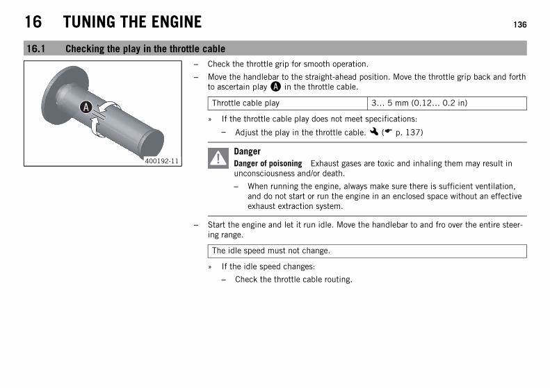
16 TUNING THE ENGINE 136
16.1 Checking the play in the throttle cable
400192-11
– Check the throttle grip for smooth operation.
– Move the handlebar to the straight-ahead position. Move the throttle grip back and forthto ascertain play in the throttle cable.
Throttle cable play 3… 5 mm (0.12… 0.2 in)
» If the throttle cable play does not meet specifications:
– Adjust the play in the throttle cable.x ( p. 137)
DangerDanger of poisoning Exhaust gases are toxic and inhaling them may result inunconsciousness and/or death.
– When running the engine, always make sure there is sufficient ventilation,and do not start or run the engine in an enclosed space without an effectiveexhaust extraction system.
– Start the engine and let it run idle. Move the handlebar to and fro over the entire steer-ing range.
The idle speed must not change.
» If the idle speed changes:
– Check the throttle cable routing.
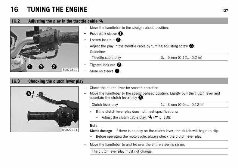
16 TUNING THE ENGINE 137
16.2 Adjusting the play in the throttle cablex
B00728-10
– Move the handlebar to the straight-ahead position.
– Push back sleeve.
– Loosen lock nut.
– Adjust the play in the throttle cable by turning adjusting screw.
Guideline
Throttle cable play 3… 5 mm (0.12… 0.2 in)
– Tighten lock nut.
– Slide on sleeve.
16.3 Checking the clutch lever play
M00001-11
– Check the clutch lever for smooth operation.
– Move the handlebar to the straight-ahead position. Lightly pull the clutch lever andascertain the clutch lever play.
Clutch lever play 1… 3 mm (0.04… 0.12 in)
» If the clutch lever play does not meet specifications:
– Adjust the clutch cable play.x ( p. 138)
NoteClutch damage If there is no play on the clutch lever, the clutch will begin to slip.
– Before operating the motorcycle, always check the clutch lever play.
– Move the handlebar to and fro over the entire steering range.
The clutch lever play must not change.
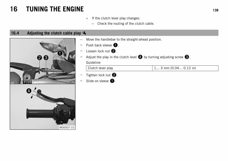
16 TUNING THE ENGINE 138
» If the clutch lever play changes:
– Check the routing of the clutch cable.
16.4 Adjusting the clutch cable playx
M00007-10
– Move the handlebar to the straight-ahead position.
– Push back sleeve.
– Loosen lock nut.
– Adjust the play in the clutch level by turning adjusting screw.
Guideline
Clutch lever play 1… 3 mm (0.04… 0.12 in)
– Tighten lock nut.
– Slide on sleeve.
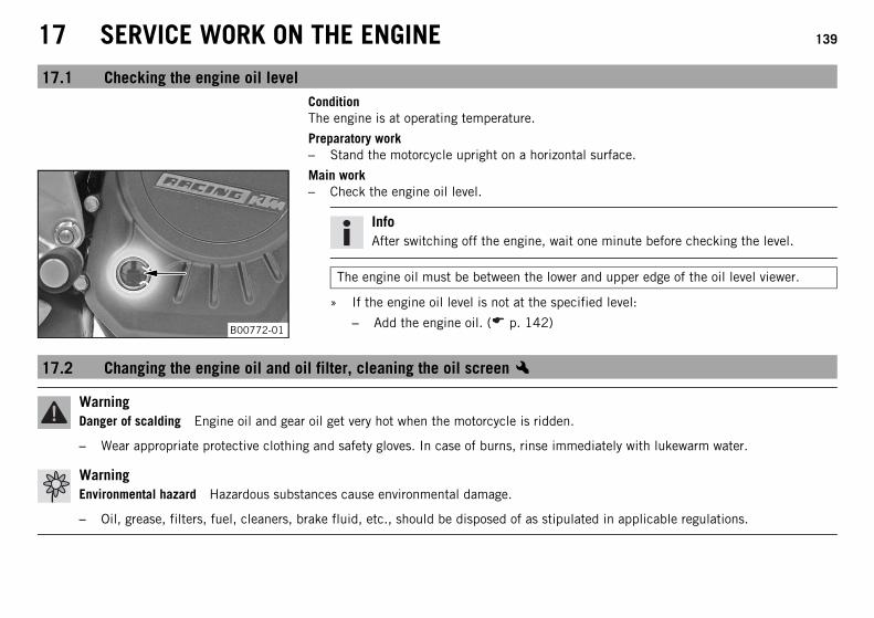
17 SERVICE WORK ON THE ENGINE 139
17.1 Checking the engine oil levelConditionThe engine is at operating temperature.
Preparatory work– Stand the motorcycle upright on a horizontal surface.
B00772-01
Main work– Check the engine oil level.
InfoAfter switching off the engine, wait one minute before checking the level.
The engine oil must be between the lower and upper edge of the oil level viewer.
» If the engine oil level is not at the specified level:
– Add the engine oil. ( p. 142)
17.2 Changing the engine oil and oil filter, cleaning the oil screenx
WarningDanger of scalding Engine oil and gear oil get very hot when the motorcycle is ridden.
– Wear appropriate protective clothing and safety gloves. In case of burns, rinse immediately with lukewarm water.
WarningEnvironmental hazard Hazardous substances cause environmental damage.
– Oil, grease, filters, fuel, cleaners, brake fluid, etc., should be disposed of as stipulated in applicable regulations.
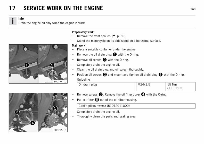
17 SERVICE WORK ON THE ENGINE 140
InfoDrain the engine oil only when the engine is warm.
Preparatory work– Remove the front spoiler. ( p. 89)
– Stand the motorcycle on its side stand on a horizontal surface.
B00774-10
Main work– Place a suitable container under the engine.
– Remove the oil drain plug with the O-ring.
– Remove oil screen with the O-ring.
– Completely drain the engine oil.
– Clean the oil drain plug and oil screen thoroughly.
– Position oil screen and mount and tighten oil drain plug with the O-ring.
Guideline
Oil drain plug M24x1.5 15 Nm(11.1 lbf ft)
B00775-10
– Remove screws. Remove the oil filter cover with the O-ring.
– Pull oil filter out of the oil filter housing.
Circlip pliers reverse (51012011000)
– Completely drain the engine oil.
– Thoroughly clean the parts and sealing area.
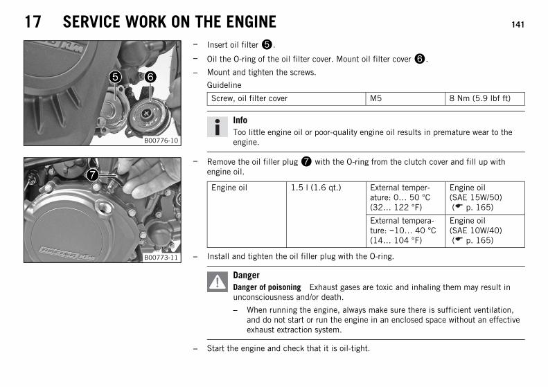
17 SERVICE WORK ON THE ENGINE 141
B00776-10
– Insert oil filter.
– Oil the O-ring of the oil filter cover. Mount oil filter cover.
– Mount and tighten the screws.
Guideline
Screw, oil filter cover M5 8 Nm (5.9 lbf ft)
InfoToo little engine oil or poor-quality engine oil results in premature wear to theengine.
B00773-11
– Remove the oil filler plug with the O-ring from the clutch cover and fill up withengine oil.
Engine oil 1.5 l (1.6 qt.) External temper-ature: 0… 50 °C(32… 122 °F)
Engine oil(SAE 15W/50)( p. 165)
External tempera-ture: −10… 40 °C(14… 104 °F)
Engine oil(SAE 10W/40)( p. 165)
– Install and tighten the oil filler plug with the O-ring.
DangerDanger of poisoning Exhaust gases are toxic and inhaling them may result inunconsciousness and/or death.
– When running the engine, always make sure there is sufficient ventilation,and do not start or run the engine in an enclosed space without an effectiveexhaust extraction system.
– Start the engine and check that it is oil-tight.
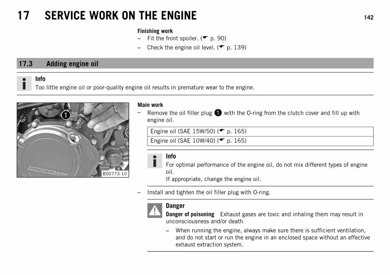
17 SERVICE WORK ON THE ENGINE 142
Finishing work– Fit the front spoiler. ( p. 90)
– Check the engine oil level. ( p. 139)
17.3 Adding engine oil
InfoToo little engine oil or poor-quality engine oil results in premature wear to the engine.
B00773-10
Main work– Remove the oil filler plug with the O-ring from the clutch cover and fill up with
engine oil.
Engine oil (SAE 15W/50) ( p. 165)
Engine oil (SAE 10W/40) ( p. 165)
InfoFor optimal performance of the engine oil, do not mix different types of engineoil.If appropriate, change the engine oil.
– Install and tighten the oil filler plug with O-ring.
DangerDanger of poisoning Exhaust gases are toxic and inhaling them may result inunconsciousness and/or death.
– When running the engine, always make sure there is sufficient ventilation,and do not start or run the engine in an enclosed space without an effectiveexhaust extraction system.
17 SERVICE WORK ON THE ENGINE 143
– Start the engine and check that it is oil-tight.
Finishing work– Check the engine oil level. ( p. 139)
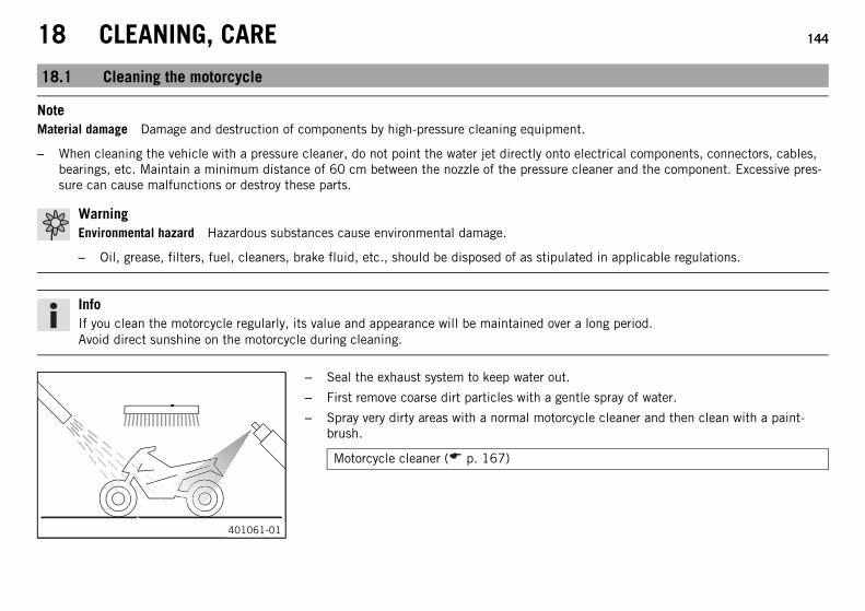
18 CLEANING, CARE 144
18.1 Cleaning the motorcycle
NoteMaterial damage Damage and destruction of components by high-pressure cleaning equipment.
– When cleaning the vehicle with a pressure cleaner, do not point the water jet directly onto electrical components, connectors, cables,bearings, etc. Maintain a minimum distance of 60 cm between the nozzle of the pressure cleaner and the component. Excessive pres-sure can cause malfunctions or destroy these parts.
WarningEnvironmental hazard Hazardous substances cause environmental damage.
– Oil, grease, filters, fuel, cleaners, brake fluid, etc., should be disposed of as stipulated in applicable regulations.
InfoIf you clean the motorcycle regularly, its value and appearance will be maintained over a long period.Avoid direct sunshine on the motorcycle during cleaning.
401061-01
– Seal the exhaust system to keep water out.
– First remove coarse dirt particles with a gentle spray of water.
– Spray very dirty areas with a normal motorcycle cleaner and then clean with a paint-brush.
Motorcycle cleaner ( p. 167)
18 CLEANING, CARE 145
InfoUse warm water containing normal motorcycle cleaner and a soft sponge.Never apply motorcycle cleaner to a dry vehicle; always rinse the vehicle withwater first.If the vehicle was operated in road salt, clean it with cold water. Warm waterwould enhance the corrosive effects of salt.
– After rinsing the motorcycle with a gentle spray of water, allow it to dry thoroughly.
– Remove the closure of the exhaust system.
WarningDanger of accidents Reduced braking efficiency due to a wet or dirty brake sys-tem.
– Clean or dry a dirty or wet brake system by riding and braking gently.
– After cleaning, ride the vehicle a short distance until the engine warms up.
InfoThe heat produced causes water at inaccessible locations in the engine and onthe brake system to evaporate.
– Push back the sleeves of the handlebar controls to allow any water that has penetratedto evaporate.
– After the motorcycle has cooled off, lubricate all moving parts and bearings.
– Clean the chain. ( p. 80)
– Treat bare metal parts (except for brake discs and exhaust system) with anti-corrosionmaterials.
Preserving materials for paints, metal and rubber ( p. 168)
– Treat all painted parts with a mild paint polish.
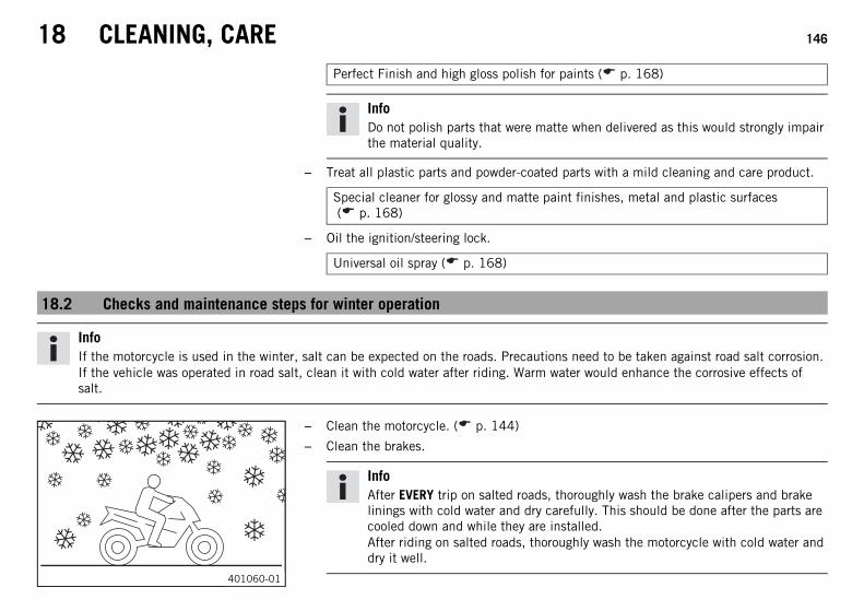
18 CLEANING, CARE 146
Perfect Finish and high gloss polish for paints ( p. 168)
InfoDo not polish parts that were matte when delivered as this would strongly impairthe material quality.
– Treat all plastic parts and powder-coated parts with a mild cleaning and care product.
Special cleaner for glossy and matte paint finishes, metal and plastic surfaces( p. 168)
– Oil the ignition/steering lock.
Universal oil spray ( p. 168)
18.2 Checks and maintenance steps for winter operation
InfoIf the motorcycle is used in the winter, salt can be expected on the roads. Precautions need to be taken against road salt corrosion.If the vehicle was operated in road salt, clean it with cold water after riding. Warm water would enhance the corrosive effects ofsalt.
401060-01
– Clean the motorcycle. ( p. 144)
– Clean the brakes.
InfoAfter EVERY trip on salted roads, thoroughly wash the brake calipers and brakelinings with cold water and dry carefully. This should be done after the parts arecooled down and while they are installed.After riding on salted roads, thoroughly wash the motorcycle with cold water anddry it well.
18 CLEANING, CARE 147
– Treat the engine, swingarm, and all other bright and zinc-plated parts (except for thebrake discs) with a wax-based corrosion inhibitor.
InfoCorrosion inhibitor is not permitted to come in contact with the brake discs asthis would greatly reduce the braking force.
– Clean the chain. ( p. 80)
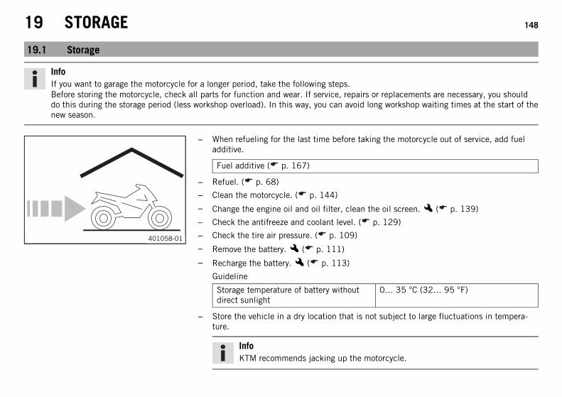
19 STORAGE 148
19.1 Storage
InfoIf you want to garage the motorcycle for a longer period, take the following steps.Before storing the motorcycle, check all parts for function and wear. If service, repairs or replacements are necessary, you shoulddo this during the storage period (less workshop overload). In this way, you can avoid long workshop waiting times at the start of thenew season.
401058-01
– When refueling for the last time before taking the motorcycle out of service, add fueladditive.
Fuel additive ( p. 167)
– Refuel. ( p. 68)
– Clean the motorcycle. ( p. 144)
– Change the engine oil and oil filter, clean the oil screen.x ( p. 139)
– Check the antifreeze and coolant level. ( p. 129)
– Check the tire air pressure. ( p. 109)
– Remove the battery.x ( p. 111)
– Recharge the battery.x ( p. 113)
Guideline
Storage temperature of battery withoutdirect sunlight
0… 35 °C (32… 95 °F)
– Store the vehicle in a dry location that is not subject to large fluctuations in tempera-ture.
InfoKTM recommends jacking up the motorcycle.
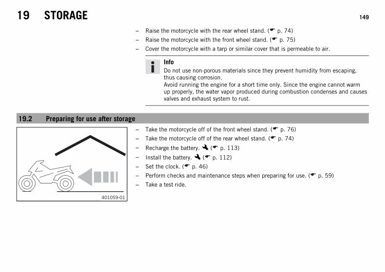
19 STORAGE 149
– Raise the motorcycle with the rear wheel stand. ( p. 74)
– Raise the motorcycle with the front wheel stand. ( p. 75)
– Cover the motorcycle with a tarp or similar cover that is permeable to air.
InfoDo not use non-porous materials since they prevent humidity from escaping,thus causing corrosion.Avoid running the engine for a short time only. Since the engine cannot warmup properly, the water vapor produced during combustion condenses and causesvalves and exhaust system to rust.
19.2 Preparing for use after storage
401059-01
– Take the motorcycle off of the front wheel stand. ( p. 76)
– Take the motorcycle off of the rear wheel stand. ( p. 74)
– Recharge the battery.x ( p. 113)
– Install the battery.x ( p. 112)
– Set the clock. ( p. 46)
– Perform checks and maintenance steps when preparing for use. ( p. 59)
– Take a test ride.
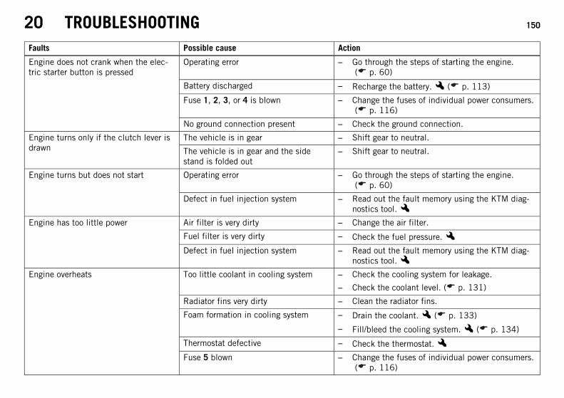
20 TROUBLESHOOTING 150
Faults Possible cause Action
Engine does not crank when the elec-tric starter button is pressed
Operating error – Go through the steps of starting the engine.( p. 60)
Battery discharged – Recharge the battery.x ( p. 113)
Fuse 1, 2, 3, or 4 is blown – Change the fuses of individual power consumers.( p. 116)
No ground connection present – Check the ground connection.
Engine turns only if the clutch lever isdrawn
The vehicle is in gear – Shift gear to neutral.
The vehicle is in gear and the sidestand is folded out
– Shift gear to neutral.
Engine turns but does not start Operating error – Go through the steps of starting the engine.( p. 60)
Defect in fuel injection system – Read out the fault memory using the KTM diag-nostics tool.x
Engine has too little power Air filter is very dirty – Change the air filter.
Fuel filter is very dirty – Check the fuel pressure.xDefect in fuel injection system – Read out the fault memory using the KTM diag-
nostics tool.xEngine overheats Too little coolant in cooling system – Check the cooling system for leakage.
– Check the coolant level. ( p. 131)
Radiator fins very dirty – Clean the radiator fins.
Foam formation in cooling system – Drain the coolant.x ( p. 133)
– Fill/bleed the cooling system.x ( p. 134)
Thermostat defective – Check the thermostat.xFuse 5 blown – Change the fuses of individual power consumers.
( p. 116)
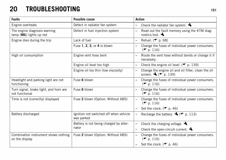
20 TROUBLESHOOTING 151
Faults Possible cause Action
Engine overheats Defect in radiator fan system – Check the radiator fan system.xThe engine diagnosis warninglamp (MIL) lights up red
Defect in fuel injection system – Read out the fault memory using the KTM diag-nostics tool.x
Engine dies during the trip Lack of fuel – Refuel. ( p. 68)
Fuse 1, 2, 3, or 4 is blown – Change the fuses of individual power consumers.( p. 116)
High oil consumption Engine vent hose bent – Route the vent hose without bends or change it ifnecessary.
Engine oil level too high – Check the engine oil level. ( p. 139)
Engine oil too thin (low viscosity) – Change the engine oil and oil filter, clean the oilscreen.x ( p. 139)
Headlight and parking light are notfunctioning
Fuse 6 blown – Change the fuses of individual power consumers.( p. 116)
Turn signal, brake light, and horn arenot functional
Fuse 6 blown – Change the fuses of individual power consumers.( p. 116)
Time is not (correctly) displayed Fuse 2 blown (Option: Without ABS) – Change the fuses of individual power consumers.( p. 116)
– Set the clock. ( p. 46)
Battery discharged Ignition not switched off when vehiclewas parked
– Recharge the battery.x ( p. 113)
Battery is not being charged by alter-nator
– Check the charging voltage.x– Check the open-circuit current.x
Combination instrument shows nothingon the display
Fuse 2 blown (Option: Without ABS) – Change the fuses of individual power consumers.( p. 116)
– Set the clock. ( p. 46)
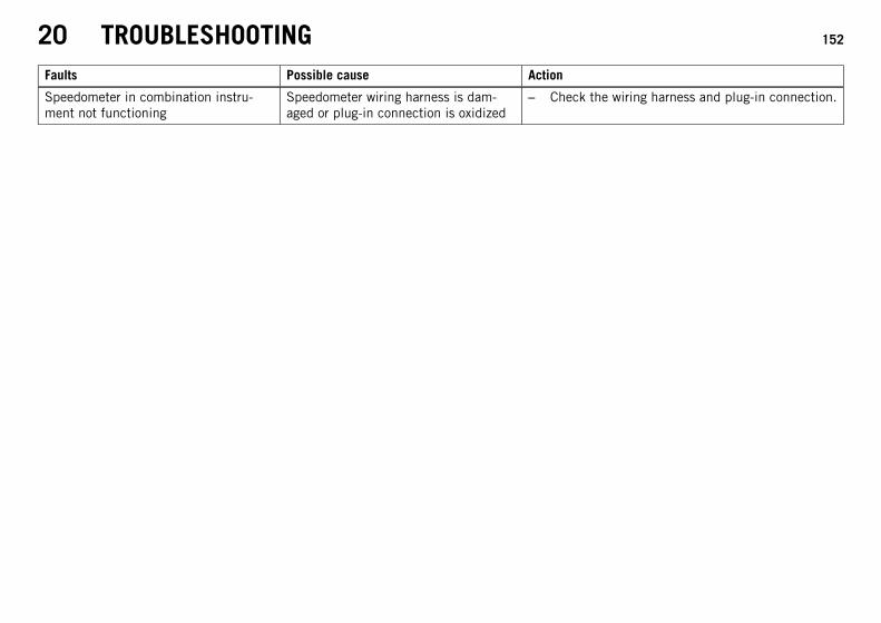
20 TROUBLESHOOTING 152
Faults Possible cause Action
Speedometer in combination instru-ment not functioning
Speedometer wiring harness is dam-aged or plug-in connection is oxidized
– Check the wiring harness and plug-in connection.
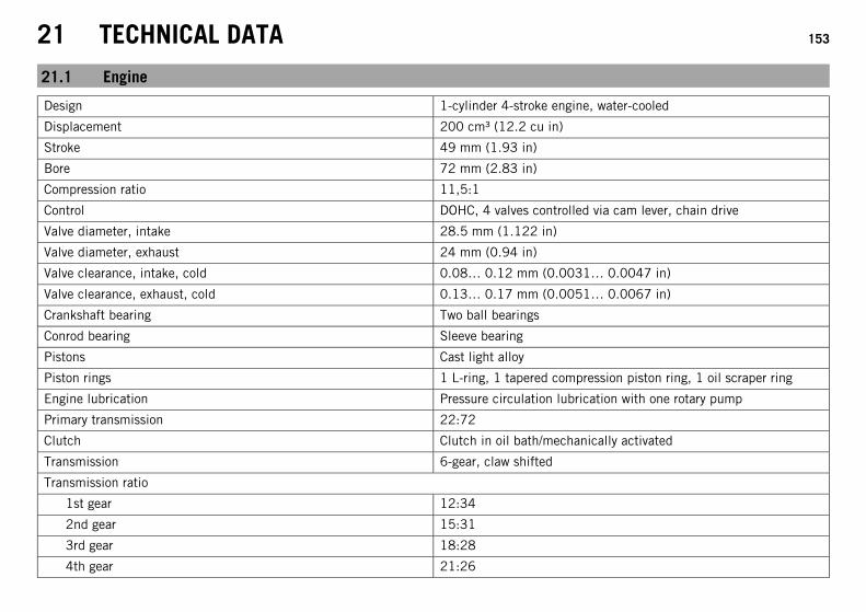
21 TECHNICAL DATA 153
21.1 Engine
Design 1-cylinder 4-stroke engine, water-cooled
Displacement 200 cm³ (12.2 cu in)
Stroke 49 mm (1.93 in)
Bore 72 mm (2.83 in)
Compression ratio 11,5:1
Control DOHC, 4 valves controlled via cam lever, chain drive
Valve diameter, intake 28.5 mm (1.122 in)
Valve diameter, exhaust 24 mm (0.94 in)
Valve clearance, intake, cold 0.08… 0.12 mm (0.0031… 0.0047 in)
Valve clearance, exhaust, cold 0.13… 0.17 mm (0.0051… 0.0067 in)
Crankshaft bearing Two ball bearings
Conrod bearing Sleeve bearing
Pistons Cast light alloy
Piston rings 1 L-ring, 1 tapered compression piston ring, 1 oil scraper ring
Engine lubrication Pressure circulation lubrication with one rotary pump
Primary transmission 22:72
Clutch Clutch in oil bath/mechanically activated
Transmission 6-gear, claw shifted
Transmission ratio
1st gear 12:34
2nd gear 15:31
3rd gear 18:28
4th gear 21:26
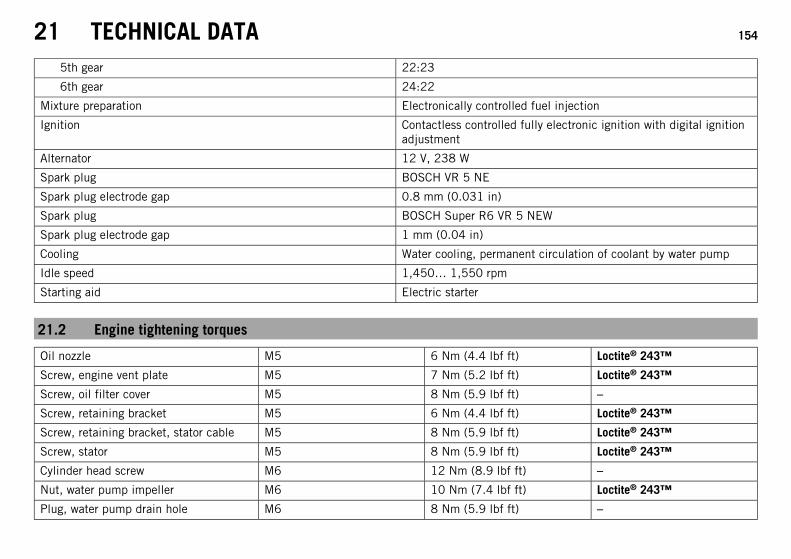
21 TECHNICAL DATA 154
5th gear 22:23
6th gear 24:22
Mixture preparation Electronically controlled fuel injection
Ignition Contactless controlled fully electronic ignition with digital ignitionadjustment
Alternator 12 V, 238 W
Spark plug BOSCH VR 5 NE
Spark plug electrode gap 0.8 mm (0.031 in)
Spark plug BOSCH Super R6 VR 5 NEW
Spark plug electrode gap 1 mm (0.04 in)
Cooling Water cooling, permanent circulation of coolant by water pump
Idle speed 1,450… 1,550 rpm
Starting aid Electric starter
21.2 Engine tightening torques
Oil nozzle M5 6 Nm (4.4 lbf ft) Loctite® 243™
Screw, engine vent plate M5 7 Nm (5.2 lbf ft) Loctite® 243™
Screw, oil filter cover M5 8 Nm (5.9 lbf ft) –
Screw, retaining bracket M5 6 Nm (4.4 lbf ft) Loctite® 243™
Screw, retaining bracket, stator cable M5 8 Nm (5.9 lbf ft) Loctite® 243™
Screw, stator M5 8 Nm (5.9 lbf ft) Loctite® 243™
Cylinder head screw M6 12 Nm (8.9 lbf ft) –
Nut, water pump impeller M6 10 Nm (7.4 lbf ft) Loctite® 243™
Plug, water pump drain hole M6 8 Nm (5.9 lbf ft) –
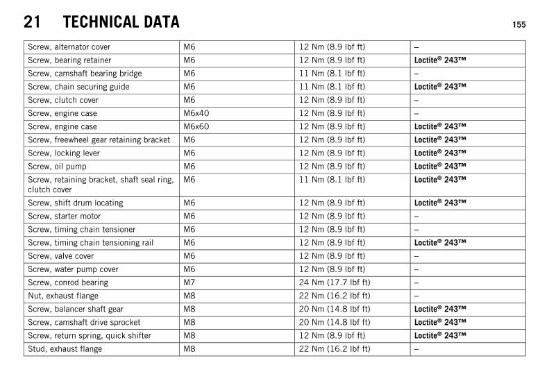
21 TECHNICAL DATA 155
Screw, alternator cover M6 12 Nm (8.9 lbf ft) –
Screw, bearing retainer M6 12 Nm (8.9 lbf ft) Loctite® 243™
Screw, camshaft bearing bridge M6 11 Nm (8.1 lbf ft) –
Screw, chain securing guide M6 11 Nm (8.1 lbf ft) Loctite® 243™
Screw, clutch cover M6 12 Nm (8.9 lbf ft) –
Screw, engine case M6x40 12 Nm (8.9 lbf ft) –
Screw, engine case M6x60 12 Nm (8.9 lbf ft) Loctite® 243™
Screw, freewheel gear retaining bracket M6 12 Nm (8.9 lbf ft) Loctite® 243™
Screw, locking lever M6 12 Nm (8.9 lbf ft) Loctite® 243™
Screw, oil pump M6 12 Nm (8.9 lbf ft) Loctite® 243™
Screw, retaining bracket, shaft seal ring,clutch cover
M6 11 Nm (8.1 lbf ft) Loctite® 243™
Screw, shift drum locating M6 12 Nm (8.9 lbf ft) Loctite® 243™
Screw, starter motor M6 12 Nm (8.9 lbf ft) –
Screw, timing chain tensioner M6 12 Nm (8.9 lbf ft) –
Screw, timing chain tensioning rail M6 12 Nm (8.9 lbf ft) Loctite® 243™
Screw, valve cover M6 12 Nm (8.9 lbf ft) –
Screw, water pump cover M6 12 Nm (8.9 lbf ft) –
Screw, conrod bearing M7 24 Nm (17.7 lbf ft) –
Nut, exhaust flange M8 22 Nm (16.2 lbf ft) –
Screw, balancer shaft gear M8 20 Nm (14.8 lbf ft) Loctite® 243™
Screw, camshaft drive sprocket M8 20 Nm (14.8 lbf ft) Loctite® 243™
Screw, return spring, quick shifter M8 12 Nm (8.9 lbf ft) Loctite® 243™
Stud, exhaust flange M8 22 Nm (16.2 lbf ft) –
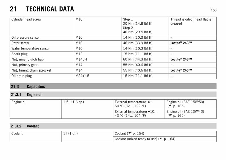
21 TECHNICAL DATA 156
Cylinder head screw M10 Step 120 Nm (14.8 lbf ft)Step 240 Nm (29.5 lbf ft)
Thread is oiled, head flat isgreased
Oil pressure sensor M10 14 Nm (10.3 lbf ft) –
Rotor screw M10 46 Nm (33.9 lbf ft) Loctite® 243™
Water temperature sensor M10 14 Nm (10.3 lbf ft) –
Spark plug M12 15 Nm (11.1 lbf ft) –
Nut, inner clutch hub M14LH 60 Nm (44.3 lbf ft) Loctite® 243™
Nut, primary gear M14 55 Nm (40.6 lbf ft) –
Nut, timing chain sprocket M14 55 Nm (40.6 lbf ft) Loctite® 243™
Oil drain plug M24x1.5 15 Nm (11.1 lbf ft) –
21.3 Capacities
21.3.1 Engine oil
Engine oil 1.5 l (1.6 qt.) External temperature: 0…50 °C (32… 122 °F)
Engine oil (SAE 15W/50)( p. 165)
External temperature: −10…40 °C (14… 104 °F)
Engine oil (SAE 10W/40)( p. 165)
21.3.2 Coolant
Coolant 1 l (1 qt.) Coolant ( p. 164)
Coolant (mixed ready to use) ( p. 164)
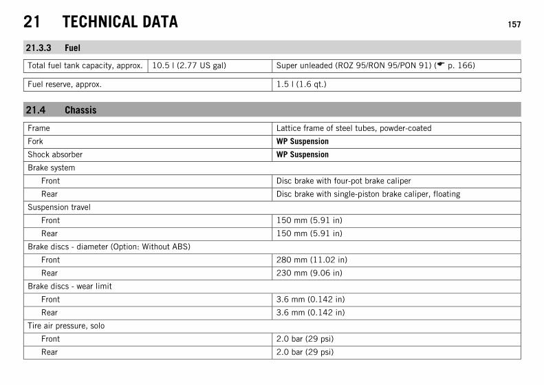
21 TECHNICAL DATA 157
21.3.3 Fuel
Total fuel tank capacity, approx. 10.5 l (2.77 US gal) Super unleaded (ROZ 95/RON 95/PON 91) ( p. 166)
Fuel reserve, approx. 1.5 l (1.6 qt.)
21.4 Chassis
Frame Lattice frame of steel tubes, powder-coated
Fork WP Suspension
Shock absorber WP Suspension
Brake system
Front Disc brake with four-pot brake caliper
Rear Disc brake with single-piston brake caliper, floating
Suspension travel
Front 150 mm (5.91 in)
Rear 150 mm (5.91 in)
Brake discs - diameter (Option: Without ABS)
Front 280 mm (11.02 in)
Rear 230 mm (9.06 in)
Brake discs - wear limit
Front 3.6 mm (0.142 in)
Rear 3.6 mm (0.142 in)
Tire air pressure, solo
Front 2.0 bar (29 psi)
Rear 2.0 bar (29 psi)
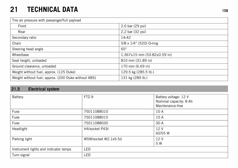
21 TECHNICAL DATA 158
Tire air pressure with passenger/full payload
Front 2.0 bar (29 psi)
Rear 2.2 bar (32 psi)
Secondary ratio 14:42
Chain 5/8 x 1/4” (520) O‑ring
Steering head angle 65°
Wheelbase 1,367±15 mm (53.82±0.59 in)
Seat height, unloaded 810 mm (31.89 in)
Ground clearance, unloaded 170 mm (6.69 in)
Weight without fuel, approx. (125 Duke) 129.5 kg (285.5 lb.)
Weight without fuel, approx. (200 Duke without ABS) 131 kg (289 lb.)
21.5 Electrical system
Battery FTZ-9 Battery voltage: 12 VNominal capacity: 8 AhMaintenance-free
Fuse 75011088010 10 A
Fuse 75011088015 15 A
Fuse 75011088030 30 A
Headlight H4/socket P43t 12 V60/55 W
Parking light W5W/socket W2.1x9.5d 12 V5 W
Instrument lights and indicator lamps LED
Turn signal LED
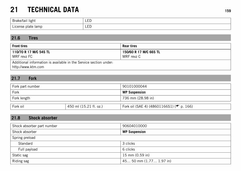
21 TECHNICAL DATA 159
Brake/tail light LED
License plate lamp LED
21.6 Tires
Front tires Rear tires
110/70 R 17 M/C 54S TLMRF revz FC
150/60 R 17 M/C 66S TLMRF revz C
Additional information is available in the Service section under:http://www.ktm.com
21.7 Fork
Fork part number 90101000044
Fork WP Suspension
Fork length 736 mm (28.98 in)
Fork oil 450 ml (15.21 fl. oz.) Fork oil (SAE 4) (48601166S1) ( p. 166)
21.8 Shock absorber
Shock absorber part number 90604010000
Shock absorber WP Suspension
Spring preload
Standard 3 clicks
Full payload 6 clicks
Static sag 15 mm (0.59 in)
Riding sag 45… 50 mm (1.77… 1.97 in)
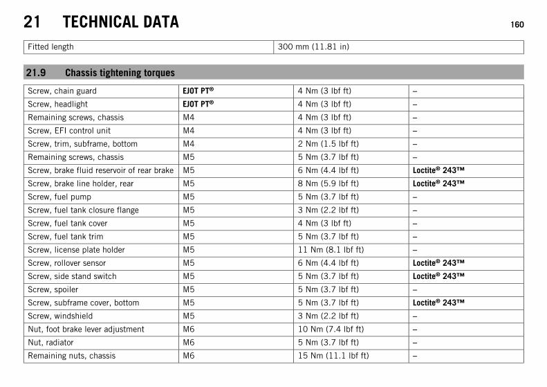
21 TECHNICAL DATA 160
Fitted length 300 mm (11.81 in)
21.9 Chassis tightening torques
Screw, chain guard EJOT PT® 4 Nm (3 lbf ft) –
Screw, headlight EJOT PT® 4 Nm (3 lbf ft) –
Remaining screws, chassis M4 4 Nm (3 lbf ft) –
Screw, EFI control unit M4 4 Nm (3 lbf ft) –
Screw, trim, subframe, bottom M4 2 Nm (1.5 lbf ft) –
Remaining screws, chassis M5 5 Nm (3.7 lbf ft) –
Screw, brake fluid reservoir of rear brake M5 6 Nm (4.4 lbf ft) Loctite® 243™
Screw, brake line holder, rear M5 8 Nm (5.9 lbf ft) Loctite® 243™
Screw, fuel pump M5 5 Nm (3.7 lbf ft) –
Screw, fuel tank closure flange M5 3 Nm (2.2 lbf ft) –
Screw, fuel tank cover M5 4 Nm (3 lbf ft) –
Screw, fuel tank trim M5 5 Nm (3.7 lbf ft) –
Screw, license plate holder M5 11 Nm (8.1 lbf ft) –
Screw, rollover sensor M5 6 Nm (4.4 lbf ft) Loctite® 243™
Screw, side stand switch M5 5 Nm (3.7 lbf ft) Loctite® 243™
Screw, spoiler M5 5 Nm (3.7 lbf ft) –
Screw, subframe cover, bottom M5 5 Nm (3.7 lbf ft) Loctite® 243™
Screw, windshield M5 3 Nm (2.2 lbf ft) –
Nut, foot brake lever adjustment M6 10 Nm (7.4 lbf ft) –
Nut, radiator M6 5 Nm (3.7 lbf ft) –
Remaining nuts, chassis M6 15 Nm (11.1 lbf ft) –
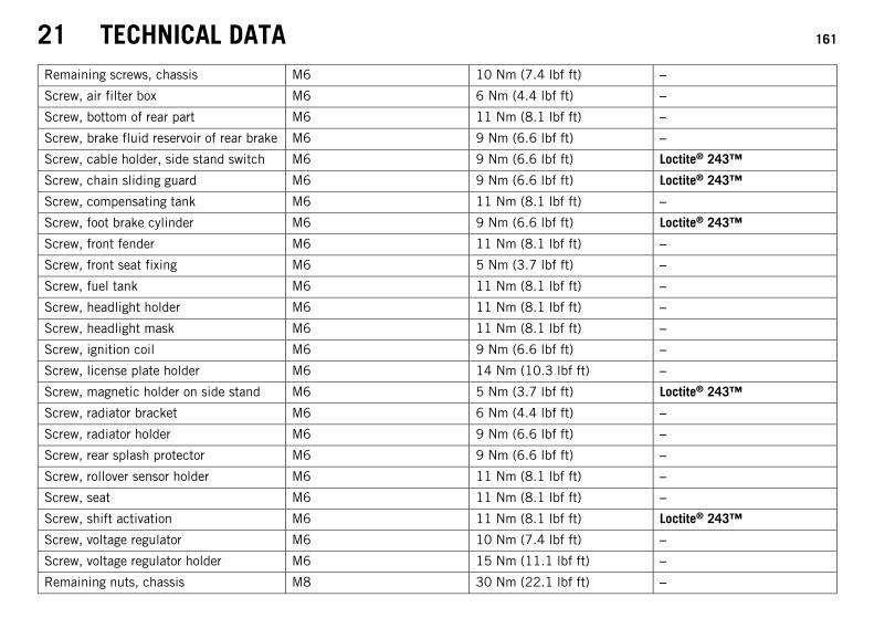
21 TECHNICAL DATA 161
Remaining screws, chassis M6 10 Nm (7.4 lbf ft) –
Screw, air filter box M6 6 Nm (4.4 lbf ft) –
Screw, bottom of rear part M6 11 Nm (8.1 lbf ft) –
Screw, brake fluid reservoir of rear brake M6 9 Nm (6.6 lbf ft) –
Screw, cable holder, side stand switch M6 9 Nm (6.6 lbf ft) Loctite® 243™
Screw, chain sliding guard M6 9 Nm (6.6 lbf ft) Loctite® 243™
Screw, compensating tank M6 11 Nm (8.1 lbf ft) –
Screw, foot brake cylinder M6 9 Nm (6.6 lbf ft) Loctite® 243™
Screw, front fender M6 11 Nm (8.1 lbf ft) –
Screw, front seat fixing M6 5 Nm (3.7 lbf ft) –
Screw, fuel tank M6 11 Nm (8.1 lbf ft) –
Screw, headlight holder M6 11 Nm (8.1 lbf ft) –
Screw, headlight mask M6 11 Nm (8.1 lbf ft) –
Screw, ignition coil M6 9 Nm (6.6 lbf ft) –
Screw, license plate holder M6 14 Nm (10.3 lbf ft) –
Screw, magnetic holder on side stand M6 5 Nm (3.7 lbf ft) Loctite® 243™
Screw, radiator bracket M6 6 Nm (4.4 lbf ft) –
Screw, radiator holder M6 9 Nm (6.6 lbf ft) –
Screw, rear splash protector M6 9 Nm (6.6 lbf ft) –
Screw, rollover sensor holder M6 11 Nm (8.1 lbf ft) –
Screw, seat M6 11 Nm (8.1 lbf ft) –
Screw, shift activation M6 11 Nm (8.1 lbf ft) Loctite® 243™
Screw, voltage regulator M6 10 Nm (7.4 lbf ft) –
Screw, voltage regulator holder M6 15 Nm (11.1 lbf ft) –
Remaining nuts, chassis M8 30 Nm (22.1 lbf ft) –
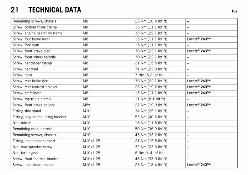
21 TECHNICAL DATA 162
Remaining screws, chassis M8 25 Nm (18.4 lbf ft) –
Screw, bottom triple clamp M8 15 Nm (11.1 lbf ft) –
Screw, engine bearer on frame M8 30 Nm (22.1 lbf ft) –
Screw, foot brake lever M8 15 Nm (11.1 lbf ft) Loctite® 243™
Screw, fork stub M8 15 Nm (11.1 lbf ft) –
Screw, front brake disc M8 30 Nm (22.1 lbf ft) Loctite® 243™
Screw, front wheel spindle M8 30 Nm (22.1 lbf ft) –
Screw, handlebar clamp M8 21 Nm (15.5 lbf ft) –
Screw, handrail M8 31 Nm (22.9 lbf ft) –
Screw, horn M8 7 Nm (5.2 lbf ft) –
Screw, rear brake disc M8 30 Nm (22.1 lbf ft) Loctite® 243™
Screw, rear footrest bracket M8 26 Nm (19.2 lbf ft) Loctite® 243™
Screw, shift lever M8 15 Nm (11.1 lbf ft) Loctite® 243™
Screw, top triple clamp M8 11 Nm (8.1 lbf ft) –
Screw, front brake caliper M8x1 27 Nm (19.9 lbf ft) Loctite® 243™
Fitting side stand M10 34 Nm (25.1 lbf ft) –
Fitting, engine mounting bracket M10 55 Nm (40.6 lbf ft) –
Nut, mirror M10 16 Nm (11.8 lbf ft) –
Remaining nuts, chassis M10 50 Nm (36.9 lbf ft) –
Remaining screws, chassis M10 45 Nm (33.2 lbf ft) –
Fitting, handlebar support M10x1.25 21 Nm (15.5 lbf ft) –
Nut, rear sprocket screw M10x1.25 32 Nm (23.6 lbf ft) –
Nut, turn signal M10x1.25 6 Nm (4.4 lbf ft) –
Screw, front footrest bracket M10x1.25 46 Nm (33.9 lbf ft) –
Screw, side stand bracket M10x1.25 25 Nm (18.4 lbf ft) Loctite® 243™
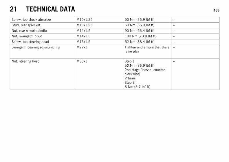
21 TECHNICAL DATA 163
Screw, top shock absorber M10x1.25 50 Nm (36.9 lbf ft) –
Stud, rear sprocket M10x1.25 50 Nm (36.9 lbf ft) –
Nut, rear wheel spindle M14x1.5 90 Nm (66.4 lbf ft) –
Nut, swingarm pivot M14x1.5 100 Nm (73.8 lbf ft) –
Screw, top steering head M16x1.5 52 Nm (38.4 lbf ft) –
Swingarm bearing adjusting ring M22x1 Tighten and ensure that thereis no play
–
Nut, steering head M30x1 Step 150 Nm (36.9 lbf ft)2nd stage (loosen, counter-clockwise)2 turnsStep 35 Nm (3.7 lbf ft)
–
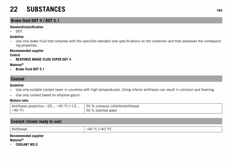
22 SUBSTANCES 164
Brake fluid DOT 4 / DOT 5.1Standard/classification– DOT
Guideline– Use only brake fluid that complies with the specified standard (see specifications on the container) and that possesses the correspond-
ing properties.
Recommended supplierCastrol– RESPONSE BRAKE FLUID SUPER DOT 4
Motorex®
– Brake Fluid DOT 5.1
CoolantGuideline– Use only suitable coolant (even in countries with high temperatures). Using inferior antifreeze can result in corrosion and foaming.
– Use only coolant based on ethylene glycol.
Mixture ratio
Antifreeze protection: −25… −45 °C (−13…−49 °F)
50 % corrosion inhibitor/antifreeze50 % distilled water
Coolant (mixed ready to use)
Antifreeze −40 °C (−40 °F)
Recommended supplierMotorex®
– COOLANT M5.0
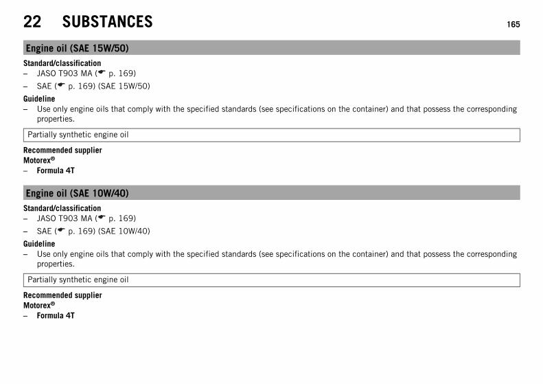
22 SUBSTANCES 165
Engine oil (SAE 15W/50)Standard/classification– JASO T903 MA ( p. 169)
– SAE ( p. 169) (SAE 15W/50)
Guideline– Use only engine oils that comply with the specified standards (see specifications on the container) and that possess the corresponding
properties.
Partially synthetic engine oil
Recommended supplierMotorex®
– Formula 4T
Engine oil (SAE 10W/40)Standard/classification– JASO T903 MA ( p. 169)
– SAE ( p. 169) (SAE 10W/40)
Guideline– Use only engine oils that comply with the specified standards (see specifications on the container) and that possess the corresponding
properties.
Partially synthetic engine oil
Recommended supplierMotorex®
– Formula 4T
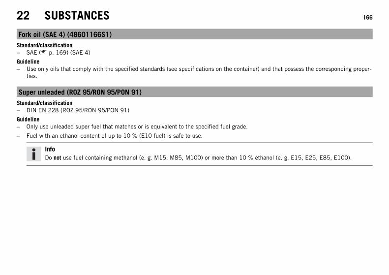
22 SUBSTANCES 166
Fork oil (SAE 4) (48601166S1)Standard/classification– SAE ( p. 169) (SAE 4)
Guideline– Use only oils that comply with the specified standards (see specifications on the container) and that possess the corresponding proper-
ties.
Super unleaded (ROZ 95/RON 95/PON 91)Standard/classification– DIN EN 228 (ROZ 95/RON 95/PON 91)
Guideline– Only use unleaded super fuel that matches or is equivalent to the specified fuel grade.
– Fuel with an ethanol content of up to 10 % (E10 fuel) is safe to use.
InfoDo not use fuel containing methanol (e. g. M15, M85, M100) or more than 10 % ethanol (e. g. E15, E25, E85, E100).
23 AUXILIARY SUBSTANCES 167
Chain cleanerRecommended supplierMotorex®
– Chain Clean
Chain lube for road useGuideline
Recommended supplierMotorex®
– Chainlube Road
Fuel additiveRecommended supplierMotorex®
– Fuel Stabilizer
Long-life greaseRecommended supplierMotorex®
– Bike Grease 2000
Motorcycle cleanerRecommended supplierMotorex®
– Moto Clean
23 AUXILIARY SUBSTANCES 168
Perfect Finish and high gloss polish for paintsRecommended supplierMotorex®
– Moto Polish & Shine
Preserving materials for paints, metal and rubberRecommended supplierMotorex®
– Moto Protect
Special cleaner for glossy and matte paint finishes, metal and plastic surfacesRecommended supplierMotorex®
– Quick Cleaner
Universal oil sprayRecommended supplierMotorex®
– Joker 440 Synthetic
24 STANDARDS 169
JASO T903 MADifferent technical development directions required a new specification for 4-stroke motorcycles – the JASO T903 MA Standard. Ear-lier, engine oils from the automobile industry were used for 4-stroke motorcycles because there was no separate motorcycle specification.Whereas long service intervals are demanded for automobile engines, high performance at high engine speeds are in the foreground formotorcycle engines. In most motorcycles, the gearbox and the clutch are lubricated with the same oil as the engine. The JASO MA Stan-dard meets these special requirements.
SAEThe SAE viscosity classes were defined by the Society of Automotive Engineers and are used for classifying oils according to their viscos-ity. The viscosity describes only one property of oil and says nothing about quality.
INDEX 170
INDEX
A
Accessories . . . . . . . . . . . . . . . . . . . . . . . . . . . . . . . . . . . . 13
Antifreezechecking . . . . . . . . . . . . . . . . . . . . . . . . . . . . . . . . . . 129
Auxiliary substances . . . . . . . . . . . . . . . . . . . . . . . . . . . . . . 13
B
Baggage . . . . . . . . . . . . . . . . . . . . . . . . . . . . . . . . . . . . . . 57
Batteryinstalling . . . . . . . . . . . . . . . . . . . . . . . . . . . . . . . . . . 112recharging . . . . . . . . . . . . . . . . . . . . . . . . . . . . . . . . . 113removing . . . . . . . . . . . . . . . . . . . . . . . . . . . . . . . . . . 111
Brake discschecking . . . . . . . . . . . . . . . . . . . . . . . . . . . . . . . . . . . 91
Brake fluidfront brake, adding . . . . . . . . . . . . . . . . . . . . . . . . . . . . 92rear brake, adding . . . . . . . . . . . . . . . . . . . . . . . . . . . . 97
Brake fluid levelfront brake, checking . . . . . . . . . . . . . . . . . . . . . . . . . . 91rear brake, checking . . . . . . . . . . . . . . . . . . . . . . . . . . . 97
Brake liningsfront brake, checking . . . . . . . . . . . . . . . . . . . . . . . . . . 94rear brake, checking . . . . . . . . . . . . . . . . . . . . . . . . . . . 99
Brakes . . . . . . . . . . . . . . . . . . . . . . . . . . . . . . . . . . . . . . . 64Brakes, applying . . . . . . . . . . . . . . . . . . . . . . . . . . . . . . . . . 64
C
Capacitycoolant . . . . . . . . . . . . . . . . . . . . . . . . . . . . . . . . . . . 156engine oil . . . . . . . . . . . . . . . . . . . . . . . . . . . . . 141, 156fuel . . . . . . . . . . . . . . . . . . . . . . . . . . . . . . . . . . 69, 157
Chainchain dirt accumulation, checking . . . . . . . . . . . . . . . . . 80checking . . . . . . . . . . . . . . . . . . . . . . . . . . . . . . . . . . . 85cleaning . . . . . . . . . . . . . . . . . . . . . . . . . . . . . . . . . . . 80
Chain tensionadjusting . . . . . . . . . . . . . . . . . . . . . . . . . . . . . . . . . . . 83checking . . . . . . . . . . . . . . . . . . . . . . . . . . . . . . . . . . . 81
Chassis number . . . . . . . . . . . . . . . . . . . . . . . . . . . . . . . . . 20
Clutch cable playadjusting . . . . . . . . . . . . . . . . . . . . . . . . . . . . . . . . . . 138
Clutch lever . . . . . . . . . . . . . . . . . . . . . . . . . . . . . . . . . . . . 22
Clutch lever playchecking . . . . . . . . . . . . . . . . . . . . . . . . . . . . . . . . . . 137
Combination instrumentactivation and test . . . . . . . . . . . . . . . . . . . . . . . . . . . . 28average fuel consumption 1/average fuel consumption 2menu . . . . . . . . . . . . . . . . . . . . . . . . . . . . . . . . . . . . . 40average fuel consumption 2/service menu . . . . . . . . . . . . 41average speed/average fuel consumption 1 menu . . . . . . . 39coolant temperature indicator . . . . . . . . . . . . . . . . . . . . . 37display . . . . . . . . . . . . . . . . . . . . . . . . . . . . . . . . . . . . 34display TRIP F . . . . . . . . . . . . . . . . . . . . . . . . . . . . . . . . 36
INDEX 171
distance menu 1 TRIP 1 . . . . . . . . . . . . . . . . . . . . . . . . . 44distance menu 2 TRIP 2 . . . . . . . . . . . . . . . . . . . . . . . . . 45filling level display in fuel tank . . . . . . . . . . . . . . . . . . . . 35function buttons . . . . . . . . . . . . . . . . . . . . . . . . . . . . . . 32indicator lamps . . . . . . . . . . . . . . . . . . . . . . . . . . . . . . 33info display . . . . . . . . . . . . . . . . . . . . . . . . . . . . . . . . . 38range/riding time menu . . . . . . . . . . . . . . . . . . . . . . . . . 43riding time/average speed menu . . . . . . . . . . . . . . . . . . . 39service/range menu . . . . . . . . . . . . . . . . . . . . . . . . . . . . 42total distance menu ODO . . . . . . . . . . . . . . . . . . . . . . . . 44warning notes . . . . . . . . . . . . . . . . . . . . . . . . . . . . . . . 29
Coolantdraining . . . . . . . . . . . . . . . . . . . . . . . . . . . . . . . . . . 133
Coolant levelchecking . . . . . . . . . . . . . . . . . . . . . . . . . . . . . . 129, 131
Cooling system . . . . . . . . . . . . . . . . . . . . . . . . . . . . . . . . 128filling/bleeding . . . . . . . . . . . . . . . . . . . . . . . . . . . . . . 134
Customer service . . . . . . . . . . . . . . . . . . . . . . . . . . . . . . . . 14
E
Electric starter button . . . . . . . . . . . . . . . . . . . . . . . . . . . . . 26Emergency OFF switch . . . . . . . . . . . . . . . . . . . . . . . . . . . . . 25
Enginerunning in . . . . . . . . . . . . . . . . . . . . . . . . . . . . . . . . . . 56
Engine number . . . . . . . . . . . . . . . . . . . . . . . . . . . . . . . . . . 20
Engine oiladding . . . . . . . . . . . . . . . . . . . . . . . . . . . . . . . . . . . 142changing . . . . . . . . . . . . . . . . . . . . . . . . . . . . . . . . . . 139
Engine oil levelchecking . . . . . . . . . . . . . . . . . . . . . . . . . . . . . . . . . . 139
Engine sprocketchecking . . . . . . . . . . . . . . . . . . . . . . . . . . . . . . . . . . . 85
Environment . . . . . . . . . . . . . . . . . . . . . . . . . . . . . . . . . . . . 11
F
Figures . . . . . . . . . . . . . . . . . . . . . . . . . . . . . . . . . . . . . . . 14
Filler capclosing . . . . . . . . . . . . . . . . . . . . . . . . . . . . . . . . . . . . 50opening . . . . . . . . . . . . . . . . . . . . . . . . . . . . . . . . . . . . 48
Filling upfuel . . . . . . . . . . . . . . . . . . . . . . . . . . . . . . . . . . . . . . 68
Foot brake lever . . . . . . . . . . . . . . . . . . . . . . . . . . . . . . . . 53free travel, adjusting . . . . . . . . . . . . . . . . . . . . . . . . . . . 96free travel, checking . . . . . . . . . . . . . . . . . . . . . . . . . . . 95
Front spoilerinstalling . . . . . . . . . . . . . . . . . . . . . . . . . . . . . . . . . . . 90removing . . . . . . . . . . . . . . . . . . . . . . . . . . . . . . . . . . . 89
Front wheelinstalling . . . . . . . . . . . . . . . . . . . . . . . . . . . . . . . . . . 102removing . . . . . . . . . . . . . . . . . . . . . . . . . . . . . . . . . . 101
Fuseindividual power consumers, changing . . . . . . . . . . . . . . 116
G
Grab handles . . . . . . . . . . . . . . . . . . . . . . . . . . . . . . . . . . . 51
INDEX 172
H
Hand brake lever . . . . . . . . . . . . . . . . . . . . . . . . . . . . . . . . 22
Headlight adjustmentadjusting . . . . . . . . . . . . . . . . . . . . . . . . . . . . . . . . . . 125checking . . . . . . . . . . . . . . . . . . . . . . . . . . . . . . . . . . 124
Headlight bulbchanging . . . . . . . . . . . . . . . . . . . . . . . . . . . . . . . . . . 118
High beam flasher button . . . . . . . . . . . . . . . . . . . . . . . . . . . 24Horn button . . . . . . . . . . . . . . . . . . . . . . . . . . . . . . . . . . . . 23
I
Ignition lock . . . . . . . . . . . . . . . . . . . . . . . . . . . . . . . . . . . 26Indicator lamps . . . . . . . . . . . . . . . . . . . . . . . . . . . . . . . . . 33
K
Key number . . . . . . . . . . . . . . . . . . . . . . . . . . . . . . . . . . . . 21
Kilometers or milesadjusting . . . . . . . . . . . . . . . . . . . . . . . . . . . . . . . . . . . 45
L
Light switch . . . . . . . . . . . . . . . . . . . . . . . . . . . . . . . . . . . . 24Loading the vehicle . . . . . . . . . . . . . . . . . . . . . . . . . . . . . . . 57
M
Motorcyclecleaning . . . . . . . . . . . . . . . . . . . . . . . . . . . . . . . . . . 144raising with the front wheel stand . . . . . . . . . . . . . . . . . . 75raising with the rear wheel stand . . . . . . . . . . . . . . . . . . . 74taking off of the front wheel stand . . . . . . . . . . . . . . . . . . 76
taking off of the rear wheel stand . . . . . . . . . . . . . . . . . . 74
O
Oil filterchanging . . . . . . . . . . . . . . . . . . . . . . . . . . . . . . . . . . 139
Oil screencleaning . . . . . . . . . . . . . . . . . . . . . . . . . . . . . . . . . . 139
Operating substances . . . . . . . . . . . . . . . . . . . . . . . . . . . . . . 13Owner's Manual . . . . . . . . . . . . . . . . . . . . . . . . . . . . . . . . . 12
P
Parking . . . . . . . . . . . . . . . . . . . . . . . . . . . . . . . . . . . . . . 66
Parking light bulbchanging . . . . . . . . . . . . . . . . . . . . . . . . . . . . . . . . . . 120
Passenger footrests . . . . . . . . . . . . . . . . . . . . . . . . . . . . . . . 52
Passenger seatmounting . . . . . . . . . . . . . . . . . . . . . . . . . . . . . . . . . . 78removing . . . . . . . . . . . . . . . . . . . . . . . . . . . . . . . . . . . 77
Play in throttle cableadjusting . . . . . . . . . . . . . . . . . . . . . . . . . . . . . . . . . . 137checking . . . . . . . . . . . . . . . . . . . . . . . . . . . . . . . . . . 136
Preparing for useadvice on first use . . . . . . . . . . . . . . . . . . . . . . . . . . . . 55after storage . . . . . . . . . . . . . . . . . . . . . . . . . . . . . . . 149checks and maintenance when preparing for use . . . . . . . . 59
Protective clothing . . . . . . . . . . . . . . . . . . . . . . . . . . . . . . . 11
INDEX 173
R
Rear hub rubber damperschecking . . . . . . . . . . . . . . . . . . . . . . . . . . . . . . . . . . 106
Rear sprocketchecking . . . . . . . . . . . . . . . . . . . . . . . . . . . . . . . . . . . 85
Rear wheelinstalling . . . . . . . . . . . . . . . . . . . . . . . . . . . . . . . . . . 105Removing . . . . . . . . . . . . . . . . . . . . . . . . . . . . . . . . . 104
Riding . . . . . . . . . . . . . . . . . . . . . . . . . . . . . . . . . . . . . . 62starting off . . . . . . . . . . . . . . . . . . . . . . . . . . . . . . . . . 61
S
Safe operation . . . . . . . . . . . . . . . . . . . . . . . . . . . . . . . . . . 10
Seatmounting . . . . . . . . . . . . . . . . . . . . . . . . . . . . . . . . . . 79removing . . . . . . . . . . . . . . . . . . . . . . . . . . . . . . . . . . . 78
Seat lock . . . . . . . . . . . . . . . . . . . . . . . . . . . . . . . . . . . . . 50Service . . . . . . . . . . . . . . . . . . . . . . . . . . . . . . . . . . . . . . . 13Service schedule . . . . . . . . . . . . . . . . . . . . . . . . . . . . . 70-71
Shift lever . . . . . . . . . . . . . . . . . . . . . . . . . . . . . . . . . . . . 52adjusting . . . . . . . . . . . . . . . . . . . . . . . . . . . . . . . . . . . 73
Shift speed RPM 1adjusting . . . . . . . . . . . . . . . . . . . . . . . . . . . . . . . . . . . 47
Shift speed RPM 2adjusting . . . . . . . . . . . . . . . . . . . . . . . . . . . . . . . . . . . 47
Shifting . . . . . . . . . . . . . . . . . . . . . . . . . . . . . . . . . . . . . . 62
Shock absorberspring preload, adjusting . . . . . . . . . . . . . . . . . . . . . . . . 72
Side stand . . . . . . . . . . . . . . . . . . . . . . . . . . . . . . . . . . . . . 54Spare parts . . . . . . . . . . . . . . . . . . . . . . . . . . . . . . . . . . . . 13Starting . . . . . . . . . . . . . . . . . . . . . . . . . . . . . . . . . . . . . . 60Steering lock . . . . . . . . . . . . . . . . . . . . . . . . . . . . . . . . . . . 26Stopping . . . . . . . . . . . . . . . . . . . . . . . . . . . . . . . . . . . . . . 66Storage . . . . . . . . . . . . . . . . . . . . . . . . . . . . . . . . . . . . . 148
T
Technical datacapacities . . . . . . . . . . . . . . . . . . . . . . . . . . . . . . . . . 156chassis . . . . . . . . . . . . . . . . . . . . . . . . . . . . . . . . . . . 157chassis tightening torques . . . . . . . . . . . . . . . . . . . . . . 160electrical system . . . . . . . . . . . . . . . . . . . . . . . . . . . . 158engine . . . . . . . . . . . . . . . . . . . . . . . . . . . . . . . . . . . 153engine tightening torques . . . . . . . . . . . . . . . . . . . . . . 154fork . . . . . . . . . . . . . . . . . . . . . . . . . . . . . . . . . . . . . 159shock absorber . . . . . . . . . . . . . . . . . . . . . . . . . . . . . . 159tires . . . . . . . . . . . . . . . . . . . . . . . . . . . . . . . . . . . . . 159
Throttle grip . . . . . . . . . . . . . . . . . . . . . . . . . . . . . . . . . . . . 23
Timeadjusting . . . . . . . . . . . . . . . . . . . . . . . . . . . . . . . . . . . 46
Tire air pressurechecking . . . . . . . . . . . . . . . . . . . . . . . . . . . . . . . . . . 109
Tire conditionchecking . . . . . . . . . . . . . . . . . . . . . . . . . . . . . . . . . . 108
Tool set . . . . . . . . . . . . . . . . . . . . . . . . . . . . . . . . . . . . . . 51
INDEX 174
Transport . . . . . . . . . . . . . . . . . . . . . . . . . . . . . . . . . . . . . 67Troubleshooting . . . . . . . . . . . . . . . . . . . . . . . . . . . . 150-152Turn signal switch . . . . . . . . . . . . . . . . . . . . . . . . . . . . . . . . 25Type label . . . . . . . . . . . . . . . . . . . . . . . . . . . . . . . . . . . . . 20
U
Use definition . . . . . . . . . . . . . . . . . . . . . . . . . . . . . . . . . . . 8
V
View of vehiclefront left . . . . . . . . . . . . . . . . . . . . . . . . . . . . . . . . . . . 16rear right . . . . . . . . . . . . . . . . . . . . . . . . . . . . . . . . . . . 18
W
Warranty . . . . . . . . . . . . . . . . . . . . . . . . . . . . . . . . . . . . . . 13
Winter operationchecks and maintenance steps . . . . . . . . . . . . . . . . . . . 146
Work rules . . . . . . . . . . . . . . . . . . . . . . . . . . . . . . . . . . . . 11

*3213118en*3213118en
03/2014
KTM-Sportmotorcycle AG5230 Mattighofen/Austriahttp://www.ktm.com
Photo: Mitterbauer/KTM