Embed Size (px)
Citation preview
dual analog filter
OWNER’S MANUAL
Page 2
Owner’s Manual VERMONA DAF -1
1 Foreword Thank you for purchasing our DAF-1 – dual analog filter. With the DAF-1 you have acquired a very flexible, stereophonic, analog, voltage-controlled, multimode filter with resonance. With two separate modulation sources and four modes of the two integrated 24 dB filters per channel, it gives you innumerable possibilities to form and manipulate sounds. You can use the DAF-1 in combination with almost every sound source you can imagine. We would like to please you to read this manual carefully for becoming familiar with the DAF-1 and to avoid wrong handling. We wish you success and much fun with your DAF-1 The VERMONA Team
Page 3
Owner’s Manual VERMONA DAF -1
2 Table of content 1 Foreword ................................................................................................................................ 2 2 Table of content...................................................................................................................... 3 3 General ................................................................................................................................... 4 4 Control Features and Connections ......................................................................................... 6 4.1 Front Panel.............................................................................................................................. 6 4.2 Rear panel............................................................................................................................... 7 5 Getting started ........................................................................................................................ 8 5.1 Unpacking............................................................................................................................... 8 5.2 Inventory................................................................................................................................. 8 5.3 Connections............................................................................................................................ 8 5.4 Setting the Input Level.......................................................................................................... 10 6 About filters .......................................................................................................................... 11 6.1 Low pass filter....................................................................................................................... 11 6.2 High pass filter...................................................................................................................... 11 6.3 Band pass ............................................................................................................................. 12 6.4 Notch filter ............................................................................................................................ 12 6.5 Resonance ............................................................................................................................ 13 6.6 Filter slope ............................................................................................................................ 13 7 The filter section of the DAF-1 .............................................................................................. 14 7.1 The mode BAND................................................................................................................... 14 7.2 The mode PARALLEL............................................................................................................ 15 7.3 The Mode NOTCH ................................................................................................................ 16 7.4 The mode SERIAL................................................................................................................. 16 8 Modulation............................................................................................................................ 17 8.1 The LFO section of the DAF-1............................................................................................... 17 8.2 The C.V. section of the DAF-1............................................................................................... 19 8.2.1 Envelope Follower............................................................................................................. 19 8.2.2 C.V. Sources...................................................................................................................... 19 8.2.3 C.V. IN/PEDAL jack assignment......................................................................................... 20 9 Technical Specifications ....................................................................................................... 21
Page 4
Owner’s Manual VERMONA DAF -1
3 General Important safety information The following safety precautions must be observed during all phases of operation, service and repair of this equipment. Failure to comply with these precautions or with specific warnings in this manual violates safety standards of design, manufacture and intended use of this equipment. The manufacturer assumes no liability for the customer’s failure to comply with these requirements! Ground and power connection To prevent the risk of electrical shock, this equipment must be grounded. The factory setting for power is already made for each country (115V AC, 230V AC). An individual setting is not allowed by virtue of safety reasons. This modification must be done by qualified personal only! Voltage peak The units are equipped to manage voltage peaks, which are often generated at live situations. When using the units with unstable voltage, please make sure that the device is grounded. Use near explosive goods The units should not be used near easy flammable or explosive goods. Dampness The units should not be used in damp or wet places. Make sure the unit is not in humid atmospheres, because this could cause condensations within the unit. WARNING: Risk of electrical shock! Connections Do only use cables, plugs and adapters, which do not affect the normal use of the unit. Cooling System The unit should not be used near heating or warm or hot fans. When using the unit in a rack or wall system, make sure that the unit has enough space to let the generated heat dissolve.
Page 5
Owner’s Manual VERMONA DAF -1
Cleaning Please clean the unit only with a dry duster. Do not use sharp cleaning fluids or water! Spare parts or modifications Modification instructions and schematic information should only be used from service departments of our official authorized VERMONA dealers. To prevent the risk of electrical shock, please do not open or modify the unit yourself. Before opening the unit always disconnect the power lead/AC Adapter. Opening or modifying the units causes the loss of warranty claims! Warranty The manufacturer warrants this product to be free of defects in material and/or workmanship. The manufacturer’s warranty does not apply to products that have been damaged due to and/or subjected to improper handling by shipping companies (forwarders), negligence, accidents, improper use or alteration not authorized by the manufacturer. This warranty is in lieu of an excluded all other warranties, expressed or implied. The manufacturer will not be liable for incidental or consequential loss or damage whatsoever, whether based upon allegations or negligence, breach of warranty, or otherwise. This disclaimer of incidental or consequential damages includes, but is not limited to, property damages, loss of profits, loss of time or other losses or inconvenient resulting from any defect in the material or workmanship of this product or any other connection with the purchase, operation or use of this product. Technical changes All changes, which improve the technical features of the units, can be made without subjective noticed by the manufacturer.
Page 6
Owner’s Manual VERMONA DAF -1
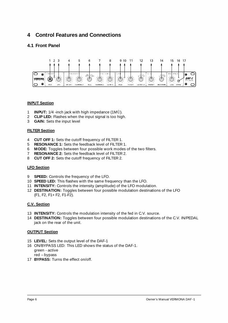
4 Control Features and Connections
4.1 Front Panel
INPUT Section 1 INPUT: 1/4 -inch jack with high impedance (1MÙ). 2 CLIP LED: Flashes when the input signal is too high. 3 GAIN: Sets the input level FILTER Section 4 CUT OFF 1: Sets the cutoff frequency of FILTER 1. 5 RESONANCE 1: Sets the feedback level of FILTER 1. 6 MODE: Toggles between four possible work modes of the two filters. 7 RESONANCE 2: Sets the feedback level of FILTER 2. 8 CUT OFF 2: Sets the cutoff frequency of FILTER 2. LFO Section 9 SPEED: Controls the frequency of the LFO. 10 SPEED LED: This flashes with the same frequency than the LFO. 11 INTENSITY: Controls the intensity (amplitude) of the LFO modulation. 12 DESTINATION: Toggles between four possible modulation destinations of the LFO
(F1, F2, F1+F2, F1-F2). C.V. Section 13 INTENSITY: Controls the modulation intensity of the fed in C.V. source. 14 DESTINATION: Toggles between four possible modulation destinations of the C.V. IN/PEDAL
jack on the rear of the unit. OUTPUT Section 15 LEVEL: Sets the output level of the DAF-1 16 ON/BYPASS LED: This LED shows the status of the DAF-1.
green - active red – bypass
17 BYPASS: Turns the effect on/off.
Page 7
Owner’s Manual VERMONA DAF -1
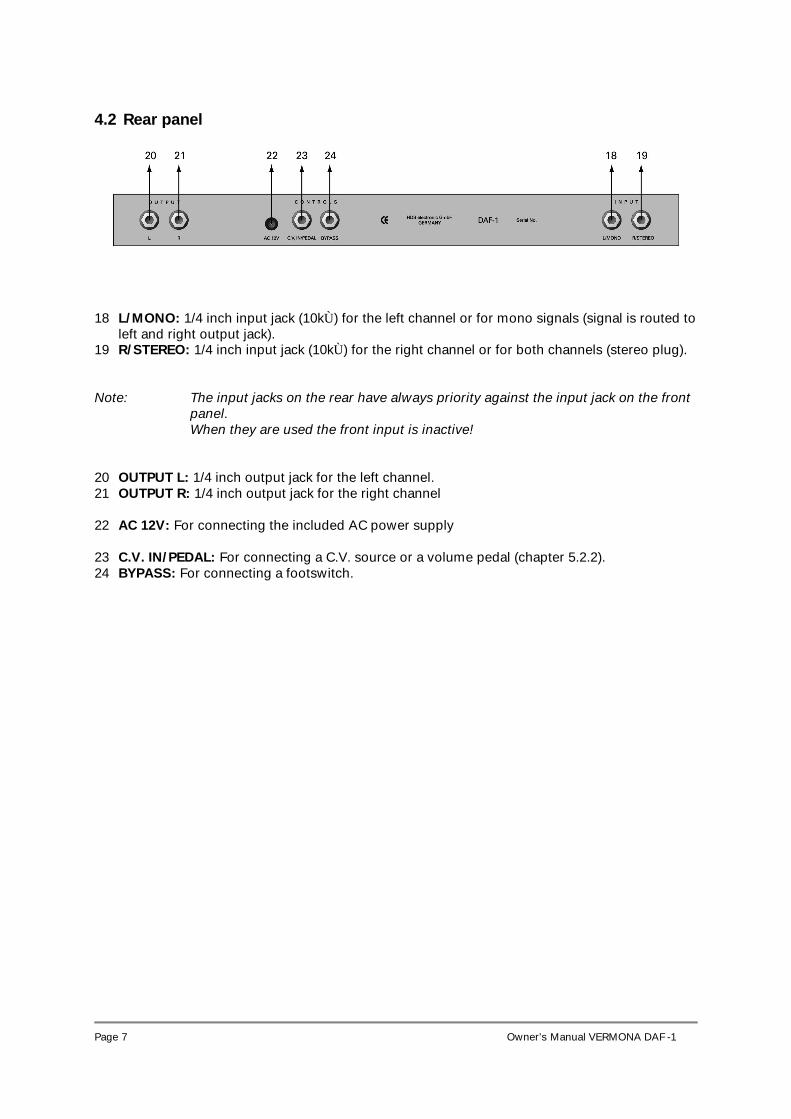
4.2 Rear panel
18 L/MONO: 1/4 inch input jack (10kÙ) for the left channel or for mono signals (signal is routed to left and right output jack).
19 R/STEREO: 1/4 inch input jack (10kÙ) for the right channel or for both channels (stereo plug). Note: The input jacks on the rear have always priority against the input jack on the front
panel. When they are used the front input is inactive!
20 OUTPUT L: 1/4 inch output jack for the left channel. 21 OUTPUT R: 1/4 inch output jack for the right channel 22 AC 12V: For connecting the included AC power supply 23 C.V. IN/PEDAL: For connecting a C.V. source or a volume pedal (chapter 5.2.2). 24 BYPASS: For connecting a footswitch.
Page 8
Owner’s Manual VERMONA DAF -1
5 Getting started
5.1 Unpacking All VERMONA devices are checked and tested carefully before packaging. In spite of the special made cartons and the solid buildup of the devices, damages during the transport are possible. Therefore we would like to please you to check the unit after receipt for seeable damages. Please do not discard the original packing! Use it for shipping the unit again, if this is necessary.
5.2 Inventory The VERMONA DAF-1 comes complete with:
• The VERMONA DAF-1 • AC 12V/830 mA adapter • Warranty card • This manual
Please ensure all the items above are included. If something is missing contact your local dealer.
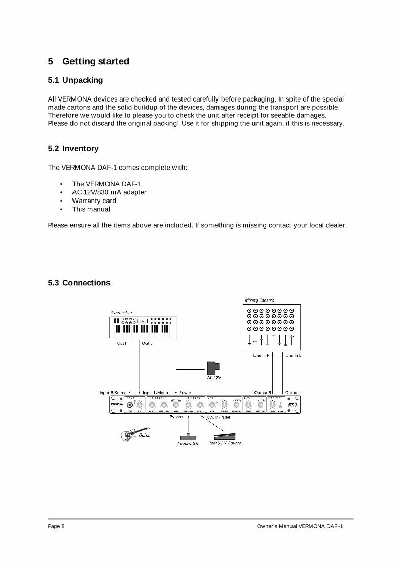
5.3 Connections
Page 9
Owner’s Manual VERMONA DAF -1
Setting up the necessary audio connections • Connect the outputs of your signal source (i.e. synthesizer, guitar) with the inputs (1, 18, 19)
of the DAF-1. • Connect the outputs (20, 21) of the DAF-1 with the inputs of your mixing console. • Connect the included AC adapter with the AC jack (22) of the DAF-1.
NOTE: The input jacks on the rear panel of the DAF-1 can be used in different ways:
- As separate input jacks for the right and the left channel (with mono plugs). - Input jack of the left channel (18) as a mono input, the signal is routed to both output jacks (20,21). - Input jack of the right channel (19) as stereo input, left and right channel are separated (with an stereo plug). The input jack on the front panel of the DAF-1 is laid out high-impedanced (1 MÙ) for use with high-resistant instruments like guitar. Impedance
NOTE: The DAF-1 is not equipped with an AC power switch. The DAF-1 is automatically
operational once you connect the DAF-1 with a wall socket. When the DAF-1 is operational, the BYPASS LED (16) illuminates.
ATTENTION: Use the DAF-1 only with the included power supply 12V AC/830mA Before connecting and disconnecting the DAF-1 to a power supply source, turn your amp’s volume control all the way down to avoid damage due to on/off switching noise!
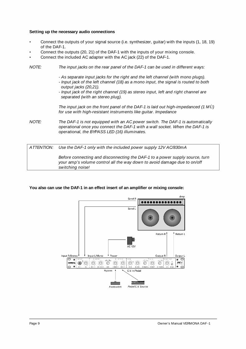
You also can use the DAF-1 in an effect insert of an amplifier or mixing console:
Page 10
Owner’s Manual VERMONA DAF -1
5.4 Setting the Input Level • Put the GAIN (3) and the LEVEL controller (15) to minimum position. • Connect an audio signal with the input jack of the DAF-1 (1, 18, 19) and turn the GAIN
controller slowly to the right, until the CLIP LED (2) illuminates. NOTE: If the input level is adjusted too high (CLIP LED illuminates constantly), you will
hear unpleasant distortion. If the input level is adjusted too low, the noise level increases. Therefore you always have to look for an optimal adjusted input level. This is a precondition for best sound quality.
Page 11
Owner’s Manual VERMONA DAF -1
6 About filters For handling the DAF-1 in the right way and for getting the best results, a little theoretical basic knowledge about the different types of filters is necessary.
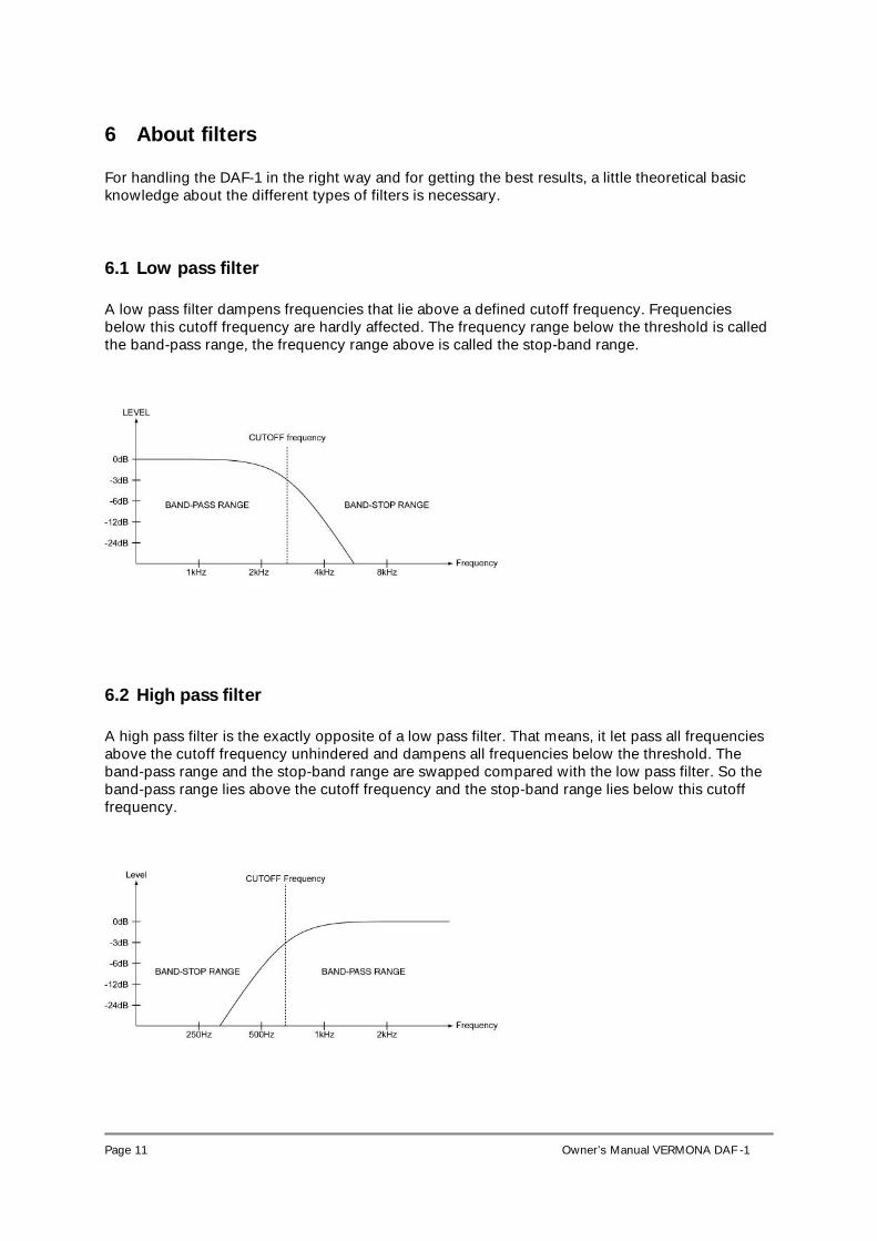
6.1 Low pass filter A low pass filter dampens frequencies that lie above a defined cutoff frequency. Frequencies below this cutoff frequency are hardly affected. The frequency range below the threshold is called the band-pass range, the frequency range above is called the stop-band range.
6.2 High pass filter A high pass filter is the exactly opposite of a low pass filter. That means, it let pass all frequencies above the cutoff frequency unhindered and dampens all frequencies below the threshold. The band-pass range and the stop-band range are swapped compared with the low pass filter. So the band-pass range lies above the cutoff frequency and the stop-band range lies below this cutoff frequency.
Page 12
Owner’s Manual VERMONA DAF -1
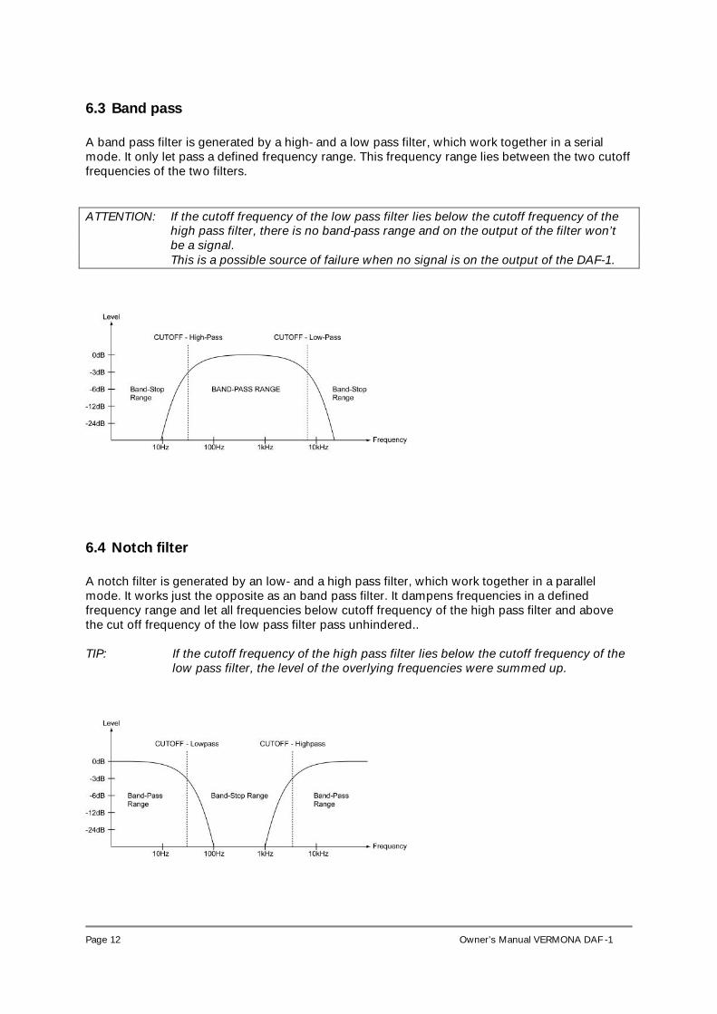
6.3 Band pass A band pass filter is generated by a high- and a low pass filter, which work together in a serial mode. It only let pass a defined frequency range. This frequency range lies between the two cutoff frequencies of the two filters. ATTENTION: If the cutoff frequency of the low pass filter lies below the cutoff frequency of the
high pass filter, there is no band-pass range and on the output of the filter won’t be a signal. This is a possible source of failure when no signal is on the output of the DAF-1.
6.4 Notch filter A notch filter is generated by an low- and a high pass filter, which work together in a parallel mode. It works just the opposite as an band pass filter. It dampens frequencies in a defined frequency range and let all frequencies below cutoff frequency of the high pass filter and above the cut off frequency of the low pass filter pass unhindered.. TIP: If the cutoff frequency of the high pass filter lies below the cutoff frequency of the
low pass filter, the level of the overlying frequencies were summed up.
Page 13
Owner’s Manual VERMONA DAF -1
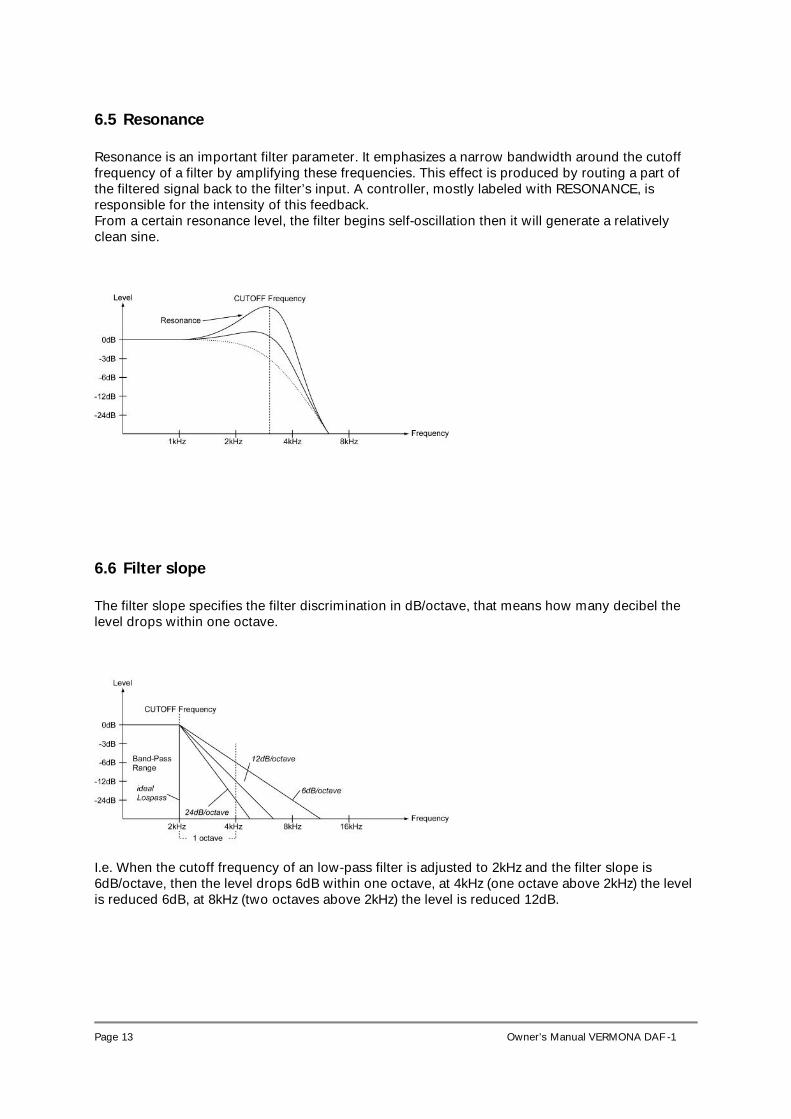
6.5 Resonance Resonance is an important filter parameter. It emphasizes a narrow bandwidth around the cutoff frequency of a filter by amplifying these frequencies. This effect is produced by routing a part of the filtered signal back to the filter’s input. A controller, mostly labeled with RESONANCE, is responsible for the intensity of this feedback. From a certain resonance level, the filter begins self-oscillation then it will generate a relatively clean sine.
6.6 Filter slope The filter slope specifies the filter discrimination in dB/octave, that means how many decibel the level drops within one octave.
I.e. When the cutoff frequency of an low-pass filter is adjusted to 2kHz and the filter slope is 6dB/octave, then the level drops 6dB within one octave, at 4kHz (one octave above 2kHz) the level is reduced 6dB, at 8kHz (two octaves above 2kHz) the level is reduced 12dB.
Page 14
Owner’s Manual VERMONA DAF -1
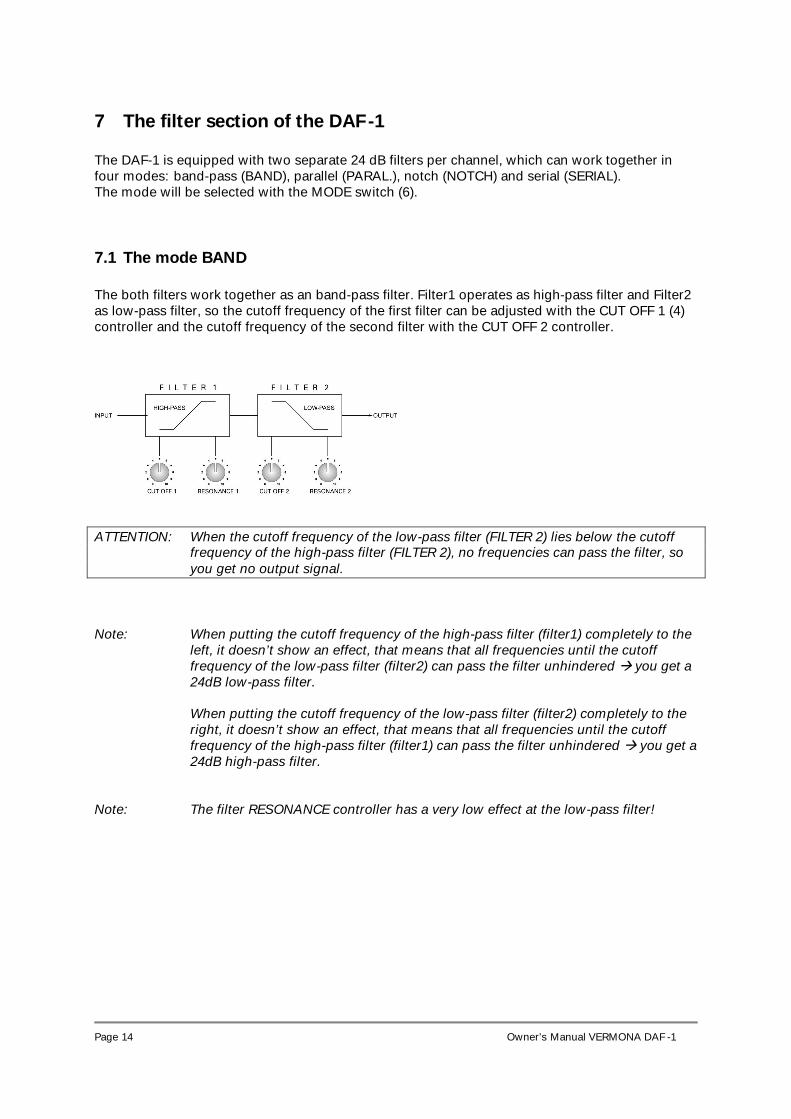
7 The filter section of the DAF -1 The DAF-1 is equipped with two separate 24 dB filters per channel, which can work together in four modes: band-pass (BAND), parallel (PARAL.), notch (NOTCH) and serial (SERIAL). The mode will be selected with the MODE switch (6).
7.1 The mode BAND The both filters work together as an band-pass filter. Filter1 operates as high-pass filter and Filter2 as low-pass filter, so the cutoff frequency of the first filter can be adjusted with the CUT OFF 1 (4) controller and the cutoff frequency of the second filter with the CUT OFF 2 controller.
ATTENTION: When the cutoff frequency of the low-pass filter (FILTER 2) lies below the cutoff
frequency of the high-pass filter (FILTER 2), no frequencies can pass the filter, so you get no output signal.
Note: When putting the cutoff frequency of the high-pass filter (filter1) completely to the
left, it doesn’t show an effect, that means that all frequencies until the cutoff frequency of the low-pass filter (filter2) can pass the filter unhindered you get a 24dB low-pass filter. When putting the cutoff frequency of the low-pass filter (filter2) completely to the right, it doesn’t show an effect, that means that all frequencies until the cutoff frequency of the high-pass filter (filter1) can pass the filter unhindered you get a 24dB high-pass filter.
Note: The filter RESONANCE controller has a very low effect at the low-pass filter!
Page 15
Owner’s Manual VERMONA DAF -1
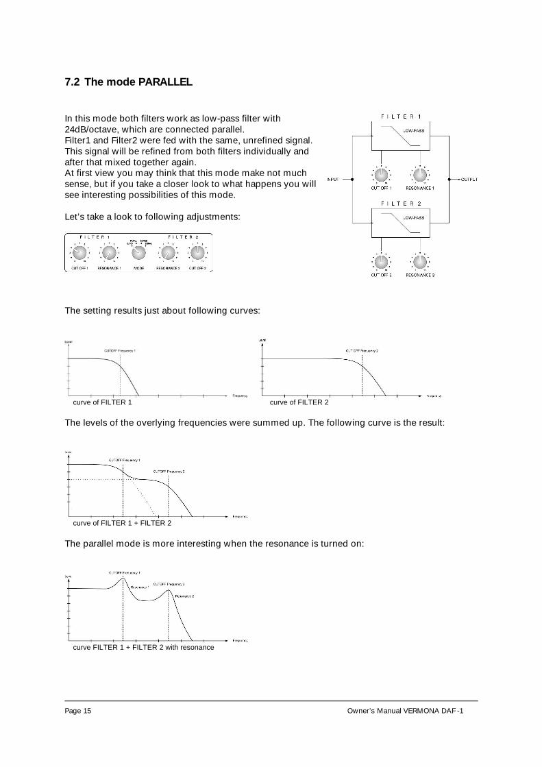
7.2 The mode PARALLEL In this mode both filters work as low-pass filter with 24dB/octave, which are connected parallel. Filter1 and Filter2 were fed with the same, unrefined signal. This signal will be refined from both filters individually and after that mixed together again. At first view you may think that this mode make not much sense, but if you take a closer look to what happens you will see interesting possibilities of this mode. Let’s take a look to following adjustments:
The setting results just about following curves:
curve of FILTER 1 curve of FILTER 2
The levels of the overlying frequencies were summed up. The following curve is the result:
curve of FILTER 1 + FILTER 2 The parallel mode is more interesting when the resonance is turned on:
curve FILTER 1 + FILTER 2 with resonance
Page 16
Owner’s Manual VERMONA DAF -1
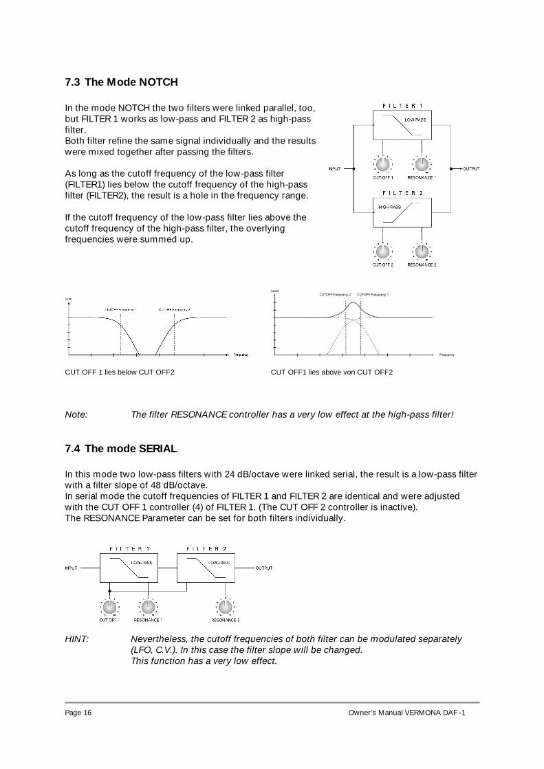
7.3 The Mode NOTCH In the mode NOTCH the two filters were linked parallel, too, but FILTER 1 works as low-pass and FILTER 2 as high-pass filter. Both filter refine the same signal individually and the results were mixed together after passing the filters. As long as the cutoff frequency of the low-pass filter (FILTER1) lies below the cutoff frequency of the high-pass filter (FILTER2), the result is a hole in the frequency range. If the cutoff frequency of the low-pass filter lies above the cutoff frequency of the high-pass filter, the overlying frequencies were summed up.
CUT OFF 1 lies below CUT OFF2 CUT OFF1 lies above von CUT OFF2 Note: The filter RESONANCE controller has a very low effect at the high-pass filter!
7.4 The mode SERIAL In this mode two low-pass filters with 24 dB/octave were linked serial, the result is a low-pass filter with a filter slope of 48 dB/octave. In serial mode the cutoff frequencies of FILTER 1 and FILTER 2 are identical and were adjusted with the CUT OFF 1 controller (4) of FILTER 1. (The CUT OFF 2 controller is inactive). The RESONANCE Parameter can be set for both filters individually.
HINT: Nevertheless, the cutoff frequencies of both filter can be modulated separately
(LFO, C.V.). In this case the filter slope will be changed. This function has a very low effect.
Page 17
Owner’s Manual VERMONA DAF -1
8 Modulation Control voltage A control voltage is a voltage, which changes values of a parameter. So a parameter, i.e. the cutoff frequency of a filter, will not be changed directly from the corresponding controller.
The CUT OFF controller changes the control voltage (C.V.) the control voltage changes the cutoff frequency.
Because of this principle of voltage control it is possible to automate parameter changes. The CUT OFF parameters of the DAF-1 can be modulated individually from two separate modulation sources.
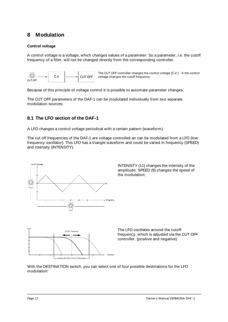
8.1 The LFO section of the DAF-1 A LFO changes a control voltage periodical with a certain pattern (waveform). The cut off frequencies of the DAF-1 are voltage controlled an can be modulated from a LFO (low frequency oscillator). This LFO has a triangle waveform and could be varied in frequency (SPEED) and intensity (INTENSITY).
INTENSITY (11) changes the intensity of the amplitude; SPEED (9) changes the speed of the modulation.
The LFO oscillates around the cutoff frequency, which is adjusted via the CUT OFF controller. (positive and negative)
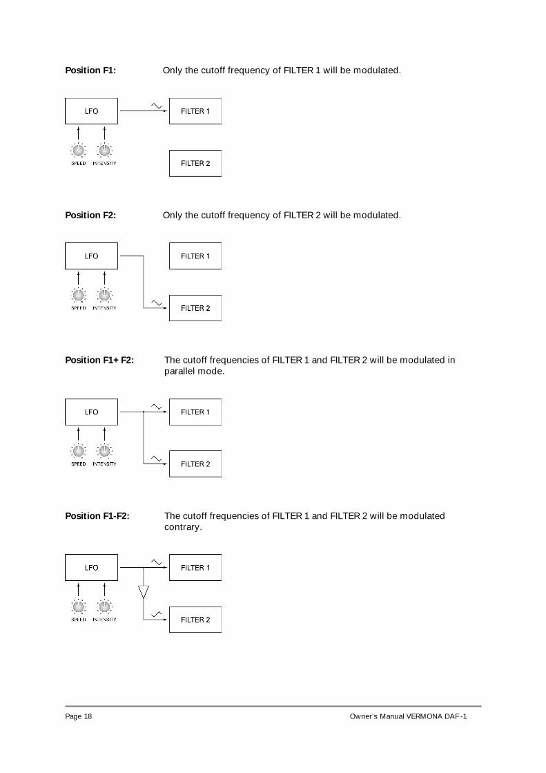
With the DESTINATION switch, you can select one of four possible destinations for the LFO modulation:
Page 18
Owner’s Manual VERMONA DAF -1
Position F1: Only the cutoff frequency of FILTER 1 will be modulated.
Position F2: Only the cutoff frequency of FILTER 2 will be modulated.
Position F1+F2: The cutoff frequencies of FILTER 1 and FILTER 2 will be modulated in
parallel mode.
Position F1-F2: The cutoff frequencies of FILTER 1 and FILTER 2 will be modulated
contrary.
Page 19
Owner’s Manual VERMONA DAF -1
8.2 The C.V. section of the DAF-1 Another possibility for controlling the cutoff frequencies is the C.V. section. This section works either with an external C.V. source or as envelope follower. The envelope follower is activated when no jack is plugged into the C.V. IN/PEDAL jack (23). When connecting a C.V. source with this jack, the settings of the C.V. section are valid for the external control voltage.
8.2.1 Envelope Follower A envelope changes the control voltage dependent to the volume of the input signal. Silent signals means a low control voltage, loud signals means a high control voltage. For a correct function of the envelope follower, the input level must be set optimal. (see. 5.4)
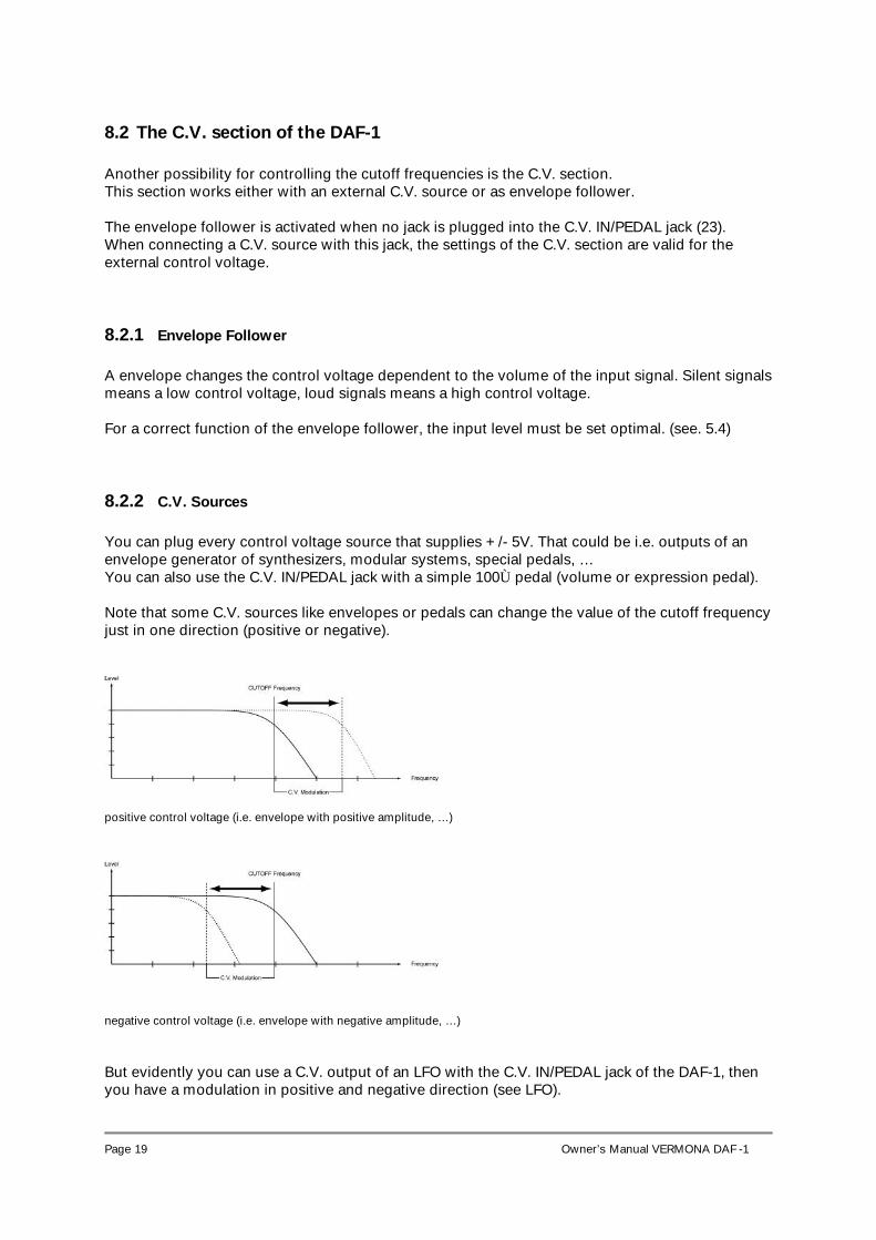
8.2.2 C.V. Sources You can plug every control voltage source that supplies +/- 5V. That could be i.e. outputs of an envelope generator of synthesizers, modular systems, special pedals, … You can also use the C.V. IN/PEDAL jack with a simple 100Ù pedal (volume or expression pedal). Note that some C.V. sources like envelopes or pedals can change the value of the cutoff frequency just in one direction (positive or negative).
positive control voltage (i.e. envelope with positive amplitude, …)
negative control voltage (i.e. envelope with negative amplitude, …) But evidently you can use a C.V. output of an LFO with the C.V. IN/PEDAL jack of the DAF-1, then you have a modulation in positive and negative direction (see LFO).
Page 20
Owner’s Manual VERMONA DAF -1
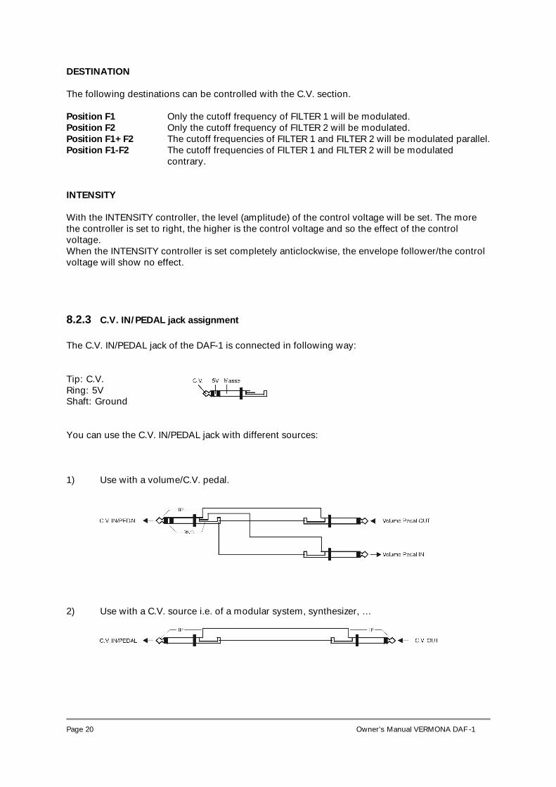
DESTINATION The following destinations can be controlled with the C.V. section. Position F1 Only the cutoff frequency of FILTER 1 will be modulated. Position F2 Only the cutoff frequency of FILTER 2 will be modulated. Position F1+F2 The cutoff frequencies of FILTER 1 and FILTER 2 will be modulated parallel. Position F1-F2 The cutoff frequencies of FILTER 1 and FILTER 2 will be modulated
contrary. INTENSITY With the INTENSITY controller, the level (amplitude) of the control voltage will be set. The more the controller is set to right, the higher is the control voltage and so the effect of the control voltage. When the INTENSITY controller is set completely anticlockwise, the envelope follower/the control voltage will show no effect.
8.2.3 C.V. IN/PEDAL jack assignment The C.V. IN/PEDAL jack of the DAF-1 is connected in following way: Tip: C.V. Ring: 5V Shaft: Ground You can use the C.V. IN/PEDAL jack with different sources: 1) Use with a volume/C.V. pedal.
2) Use with a C.V. source i.e. of a modular system, synthesizer, …
Page 21
Owner’s Manual VERMONA DAF -1
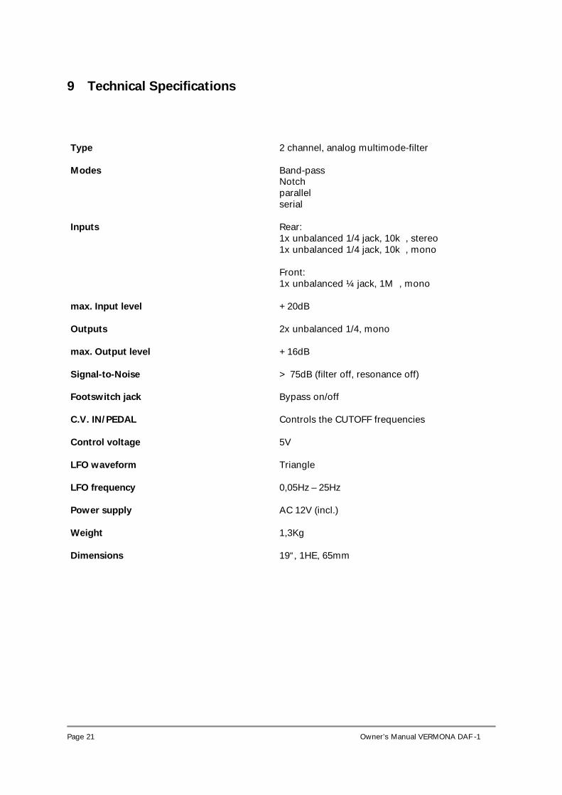
9 Technical Specifications Type 2 channel, analog multimode-filter
Modes Band-pass
Notch parallel serial
Inputs Rear: 1x unbalanced 1/4 jack, 10k�, stereo 1x unbalanced 1/4 jack, 10k�, mono Front: 1x unbalanced ¼ jack, 1M�, mono
max. Input level +20dB
Outputs 2x unbalanced 1/4, mono
max. Output level +16dB
Signal-to-Noise > 75dB (filter off, resonance off) Footswitch jack Bypass on/off
C.V. IN/PEDAL Controls the CUTOFF frequencies
Control voltage 5V
LFO waveform Triangle
LFO frequency 0,05Hz – 25Hz
Power supply AC 12V (incl.)
Weight 1,3Kg
Dimensions 19“, 1HE, 65mm
Page 22
Owner’s Manual VERMONA DAF -1
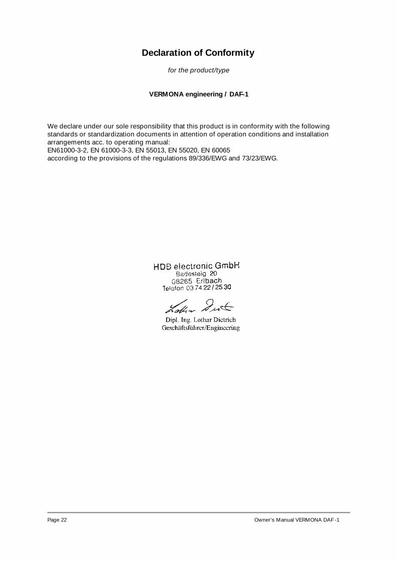
Declaration of Conformity
for the product/type
VERMONA engineering / DAF-1 We declare under our sole responsibility that this product is in conformity with the following standards or standardization documents in attention of operation conditions and installation arrangements acc. to operating manual: EN61000-3-2, EN 61000-3-3, EN 55013, EN 55020, EN 60065 according to the provisions of the regulations 89/336/EWG and 73/23/EWG.
Page 23
Owner’s Manual VERMONA DAF -1
HDB electronic GmbH – VERMONA engineering Badesteig 20
D-08265 Erlbach
Tel.: 037422/2530 Fax: 037422/2397
e-mail: [email protected]
www.vermona.com