Embed Size (px)
Citation preview
45260
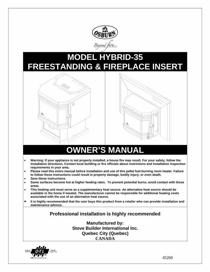
MODEL HYBRID-35 FREESTANDING & FIREPLACE INSERT
OWNER’S MANUAL • Warning: If your appliance is not properly installed, a house fire may result. For your safety, follow the
installation directions. Contact local building or fire officials about restrictions and installation inspection requirements in your area.
• Please read this entire manual before installation and use of this pellet fuel-burning room heater. Failure to follow these instructions could result in property damage, bodily injury, or even death.
• Save these instructions. • Some surfaces become hot at higher feeding rates. To prevent potential burns, avoid contact with those
areas. • This heating unit must serve as a supplementary heat source. An alternative heat source should be
available in the home if needed. The manufacturer cannot be responsible for additional heating costs associated with the use of an alternative heat source.
• It is highly recommended that the user buys this product from a retailer who can provide installation and maintenance advices.
Professional installation is highly recommended
Manufactured by:
Stove Builder International Inc. Quebec City (Quebec)
CANADA
2
INTRODUCTION Thank you for purchasing the HYBRID-35 pellet stove & insert. You are now prepared to burn wood in the most efficient, convenient way possible. To achieve the safest, most efficient and most enjoyable performance from your stove, you must do three things: 1) Install it properly; 2) Operate it correctly; and 3) Maintain it regularly. The purpose of this manual is to help you do all three. PLEASE read this entire manual before installation and use of this pellet fuel-burning room heater. Failure to follow these instructions could result in property damage, bodily injury or even death. Keep this manual handy for future reference. Your HYBRID-35 has been independently tested to ASTM E1509-04 Standard Specification for room heaters, pellet fuel burning type 1 and the HYBRID-35 insert has been independently tested to ASTM E1509-04 Standard Specification for room heaters, pellet fuel burning type 1, UL 1482-1998 Standard for solid fuel room heaters and ULC-S628-93 Standard for fireplace inserts. This pellet stove, when installed, must be electrically grounded in accordance with local codes, or in the absence of local codes, with the National Electrical Code, ANSI/NFPA 70 and CSA-C22.1. This appliance is designed for use with pelletized wood only. Do not burn coal of any type in this appliance. It is designed for residential installation according to current national and local building codes as a freestanding or insert room heater. It is also approved as a mobile home heater which is designed for connection to an outside combustion air source. The stove will not operate using natural draft or without a power source for the blowers and fuel feed system. This stove is designed to provide the optimum proportions of fuel and air to the fire in order to burn free of smoke and soot. Any blockage of the air supply to or from the stove will seriously degrade its performance and will be evidenced by a smoking exhaust and a sooting window. For best operation, the ash content of the pellet fuel should be less than 1% and the calorific value approximately 8,200 BTU/LB. Avoid burning high ash content fuels because this will rapidly fill up the burn pot and eventually cut off the combustion air supply. The HYBRID-35 should not be used for commercial or industrial applications since operational control is often not well managed in these settings
REGISTER YOU WARRANTY ONLINE
To receive full warranty coverage, you will need to show evidence of the date you purchased your unit. Keep your sales invoice. We also recommend that you register your warranty online at
www.osburn-mfg.com Registering your warranty online will help us track rapidly the
information we need on your unit.
3
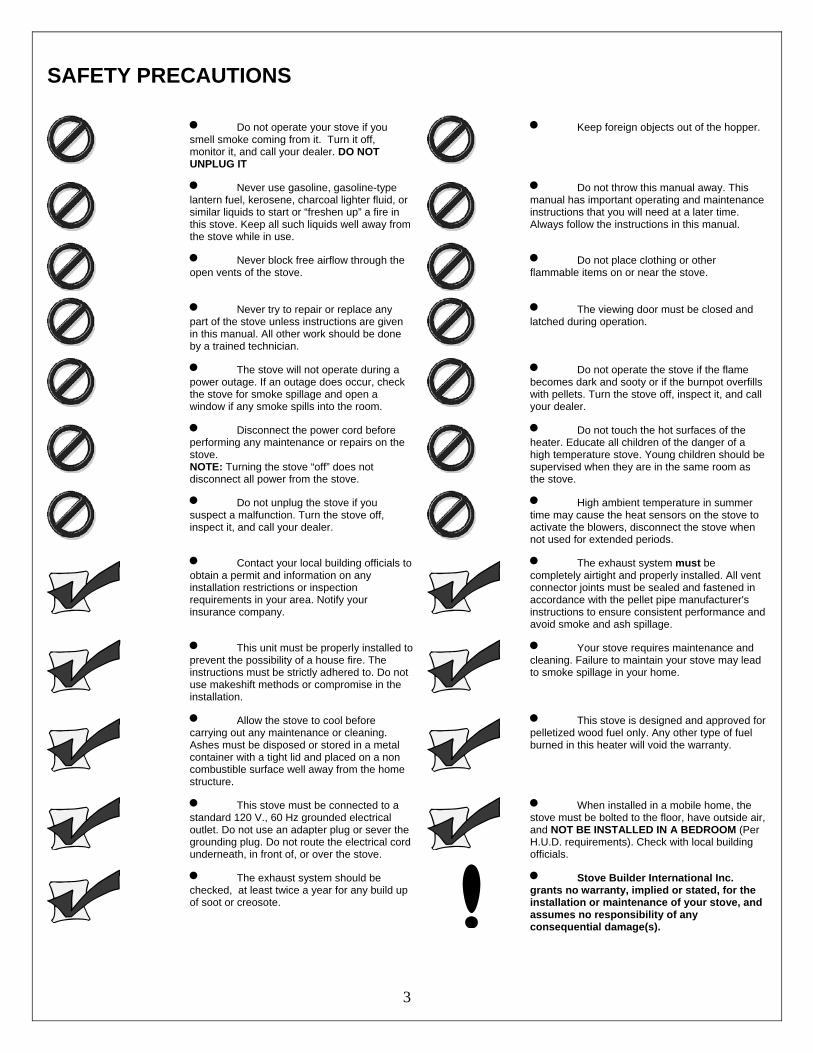
SAFETY PRECAUTIONS
• Do not operate your stove if you smell smoke coming from it. Turn it off, monitor it, and call your dealer. DO NOT UNPLUG IT
• Keep foreign objects out of the hopper.
• Never use gasoline, gasoline-type lantern fuel, kerosene, charcoal lighter fluid, or similar liquids to start or “freshen up” a fire in this stove. Keep all such liquids well away from the stove while in use.
• Do not throw this manual away. This manual has important operating and maintenance instructions that you will need at a later time. Always follow the instructions in this manual.
• Never block free airflow through the open vents of the stove.
• Do not place clothing or other flammable items on or near the stove.
• Never try to repair or replace any part of the stove unless instructions are given in this manual. All other work should be done by a trained technician.
• The viewing door must be closed and latched during operation.
• The stove will not operate during a power outage. If an outage does occur, check the stove for smoke spillage and open a window if any smoke spills into the room.
• Do not operate the stove if the flame becomes dark and sooty or if the burnpot overfills with pellets. Turn the stove off, inspect it, and call your dealer.
• Disconnect the power cord before performing any maintenance or repairs on the stove. NOTE: Turning the stove “off” does not disconnect all power from the stove.
• Do not touch the hot surfaces of the heater. Educate all children of the danger of a high temperature stove. Young children should be supervised when they are in the same room as the stove.
• Do not unplug the stove if you suspect a malfunction. Turn the stove off, inspect it, and call your dealer.
• High ambient temperature in summer time may cause the heat sensors on the stove to activate the blowers, disconnect the stove when not used for extended periods.
• Contact your local building officials to obtain a permit and information on any installation restrictions or inspection requirements in your area. Notify your insurance company.
• The exhaust system must be completely airtight and properly installed. All vent connector joints must be sealed and fastened in accordance with the pellet pipe manufacturer's instructions to ensure consistent performance and avoid smoke and ash spillage.
• This unit must be properly installed to prevent the possibility of a house fire. The instructions must be strictly adhered to. Do not use makeshift methods or compromise in the installation.
• Your stove requires maintenance and cleaning. Failure to maintain your stove may lead to smoke spillage in your home.
• Allow the stove to cool before carrying out any maintenance or cleaning. Ashes must be disposed or stored in a metal container with a tight lid and placed on a non combustible surface well away from the home structure.
• This stove is designed and approved for pelletized wood fuel only. Any other type of fuel burned in this heater will void the warranty.
• This stove must be connected to a standard 120 V., 60 Hz grounded electrical outlet. Do not use an adapter plug or sever the grounding plug. Do not route the electrical cord underneath, in front of, or over the stove.
• When installed in a mobile home, the stove must be bolted to the floor, have outside air, and NOT BE INSTALLED IN A BEDROOM (Per H.U.D. requirements). Check with local building officials.
• The exhaust system should be checked, at least twice a year for any build up of soot or creosote.
• Stove Builder International Inc. grants no warranty, implied or stated, for the installation or maintenance of your stove, and assumes no responsibility of any consequential damage(s).
4
TABLE OF CONTENTS INTRODUCTION ..................................................................................................................................................................... 2 SAFETY PRECAUTIONS ....................................................................................................................................................... 3 TABLE OF CONTENTS .......................................................................................................................................................... 4 FREESTANDING INSTALLATION......................................................................................................................................... 6
HYBRID-35 FREESTANDING PELLET STOVE ............................................................................................ 6 PREPARATION .................................................................................................................................................. 6 CLEARANCES ................................................................................................................................................... 6 COMBUSTION AIR SUPPLY ........................................................................................................................... 8 WHEN OUTSIDE AIR IS NOT USED .............................................................................................................. 8 VENTING ............................................................................................................................................................ 8 FILTERS INSTALLATION AND CLEANING ................................................................................................. 9 EQUIVALENT VENT LENGHT (EVL) .......................................................................................................... 10 INSTALLATION CONFIGURATIONS .......................................................................................................... 10
HORIZONTALLY THROUGH WALL ....................................................................................................... 10 VERTICALLY WITH NEW CHIMNEY SYSTEM ..................................................................................... 11 VERTICALLY INTO EXISTING CHIMNEY SYSTEM ............................................................................ 11 VERTICALLY INTO EXISTING MASONRY FIREPLACE ..................................................................... 12 INSTALLATION THROUGH SIDE OF MASONRY CHIMNEY ............................................................. 12
INSERT INSTALLATION ...................................................................................................................................................... 13 INSERT INTO EXISTING MASONRY FIREPLACE .................................................................................... 13 CLEARANCES ................................................................................................................................................. 14 DOOR OVERLAY INSTALLATION .............................................................................................................. 14
OPERATION ......................................................................................................................................................................... 15 PROPER FUEL .................................................................................................................................................. 15 PRE-START-UP CHECK ................................................................................................................................. 15 BUILDING A FIRE ........................................................................................................................................... 15 LIGHTING PROCEDURE ................................................................................................................................ 15 UNIT CONTROLS ............................................................................................................................................ 16
MODE BUTTON ........................................................................................................................................... 16 FUEL FEED SWITCH .................................................................................................................................. 16 NOISE REDUCER ........................................................................................................................................ 16 HEAT LEVEL ............................................................................................................................................... 16 RESET ........................................................................................................................................................... 16
OPENING DOOR .............................................................................................................................................. 16 CONVECTION BLOWERS (ROOM AIR FANS) ........................................................................................... 16 COMBEXtm ........................................................................................................................................................ 17 IF THE STOVE RUNS OUT OF PELLETS ..................................................................................................... 17 REFUELING ..................................................................................................................................................... 17 SHUTDOWN PROCEDURE ............................................................................................................................ 18 SAFETY FEATURES ....................................................................................................................................... 18 DAMPER OPERATION ................................................................................................................................... 18 OPERATING THE STOVE USING A THERMOSTAT ................................................................................. 19 THERMOSTAT INSTALLATION ................................................................................................................... 19 MODES .............................................................................................................................................................. 20
OPERATING SAFETY PRECAUTIONS .............................................................................................................................. 21 MAINTENANCE .................................................................................................................................................................... 22
ASH REMOVAL ............................................................................................................................................... 22 ASH DISPOSAL ................................................................................................................................................ 22 VACCUM USE .................................................................................................................................................. 23
5
CLEANING ....................................................................................................................................................... 23 BLOWERS AND PRESSURE SWITCH PROBE ............................................................................................ 24 CHIMNEY CLEANING .................................................................................................................................... 24 RECOMMENDED MAINTENANCE SCHEDULE ........................................................................................ 25 REMOVAL AND REPLACEMENT OF DOOR GLASS ................................................................................ 25
TROUBLESHOOTING .......................................................................................................................................................... 26 STOVE SHUTS OFF AND SHOWS WARNING CODE “P” ......................................................................... 26 STOVE SHUTS OFF AND SHOWS WARNING CODE “E” ......................................................................... 27 STOVE FEEDS PELLETS, BUT WILL NOT IGNITE AND SHOWS WARNING CODE “L” ................... 28 STOVE FEEDS PELLETS, BUT WILL NOT IGNITE AND SHOWS WARNING CODE “I” ..................... 28 STOVE STOPS FEEDING PELLETS AND SHOWS WARNING CODE “O” ............................................. 28 STOVE STOPS FEEDING PELLETS AND SHOWS WARNING CODE “H” ............................................. 29 STOVE STOPS FEEDING PELLETS AND SHOWS WARNING CODE “d” .............................................. 29 SMOKE SMELL COMING BACK INTO THE HOME .................................................................................. 30 AUGER MOTOR STOPS FEEDING PELLETS AND COMES BACK ON .................................................. 30 GLASS SOOTS UP VERY FAST .................................................................................................................... 30 FLAME IS LAZY, DARK, AND HAS BLACK TIPS ..................................................................................... 30 AFTER STOVE HAS BEEN ON FOR A WHILE, THE BURNPOT OVERFILLS ....................................... 30 WARNING CODES .......................................................................................................................................... 31 SMOKE SMELL OR SOOT BUILD-UP .......................................................................................................... 31
ELECTRICAL DIAGRAM ..................................................................................................................................................... 32 ELECTRIC SHOCK .......................................................................................................................................... 32
REPLACEMENT PARTS ...................................................................................................................................................... 33 APPENDIX A......................................................................................................................................................................... 34 APPENDIX B......................................................................................................................................................................... 35 OSBURN LIMITED LIFETIME WARRANTY ........................................................................................................................ 36
6
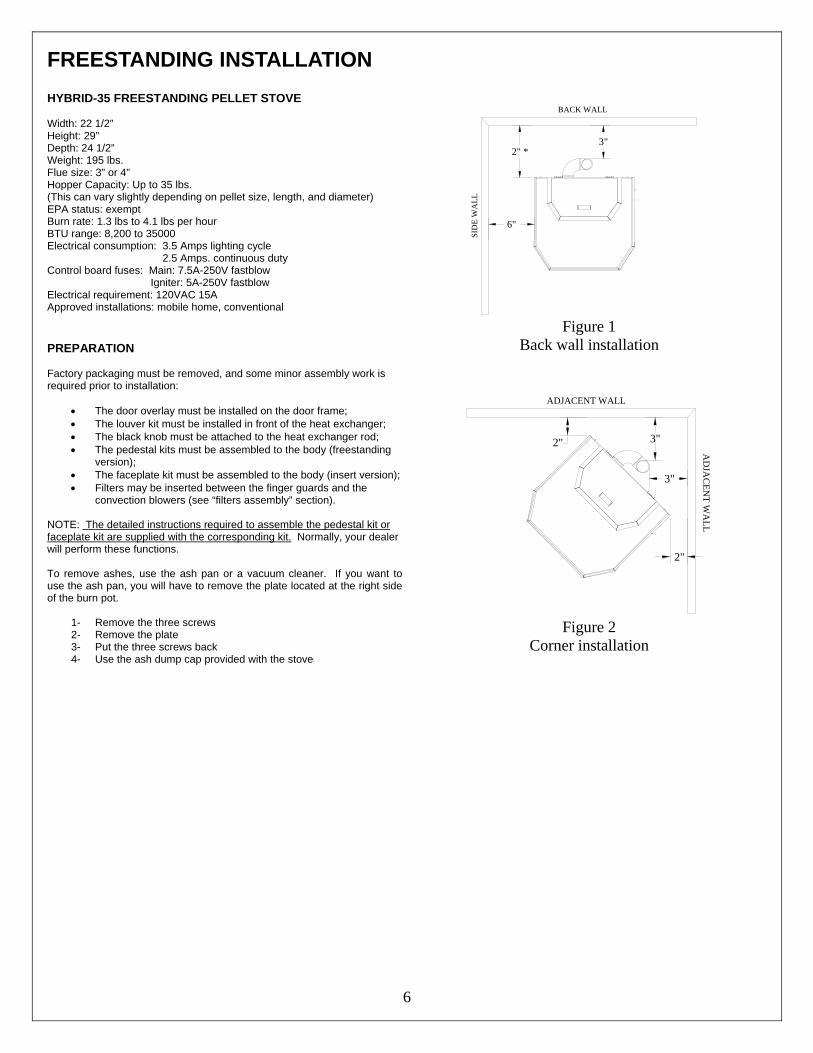
FREESTANDING INSTALLATION HYBRID-35 FREESTANDING PELLET STOVE Width: 22 1/2” Height: 29” Depth: 24 1/2” Weight: 195 lbs. Flue size: 3” or 4” Hopper Capacity: Up to 35 lbs. (This can vary slightly depending on pellet size, length, and diameter) EPA status: exempt Burn rate: 1.3 lbs to 4.1 lbs per hour BTU range: 8,200 to 35000 Electrical consumption: 3.5 Amps lighting cycle 2.5 Amps. continuous duty Control board fuses: Main: 7.5A-250V fastblow Igniter: 5A-250V fastblow Electrical requirement: 120VAC 15A Approved installations: mobile home, conventional
PREPARATION Factory packaging must be removed, and some minor assembly work is required prior to installation:
• The door overlay must be installed on the door frame; • The louver kit must be installed in front of the heat exchanger; • The black knob must be attached to the heat exchanger rod; • The pedestal kits must be assembled to the body (freestanding
version); • The faceplate kit must be assembled to the body (insert version); • Filters may be inserted between the finger guards and the
convection blowers (see “filters assembly” section). NOTE: The detailed instructions required to assemble the pedestal kit or faceplate kit are supplied with the corresponding kit. Normally, your dealer will perform these functions. To remove ashes, use the ash pan or a vacuum cleaner. If you want to use the ash pan, you will have to remove the plate located at the right side of the burn pot.
1- Remove the three screws 2- Remove the plate 3- Put the three screws back 4- Use the ash dump cap provided with the stove
SID
E W
ALL
6"
BACK WALL
2" *3"
Figure 1
Back wall installation
2" 3"
3"
2"
ADJACENT WALL
AD
JAC
ENT W
ALL
Figure 2
Corner installation
7
CLEARANCES The HYBRID-35 has been tested and listed for installation in regular and mobile homes.(refer figure 1 & 2)
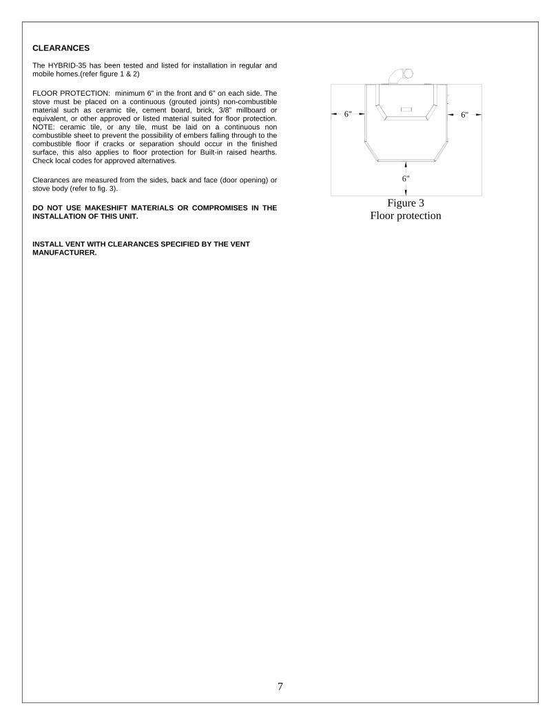
FLOOR PROTECTION: minimum 6” in the front and 6” on each side. The stove must be placed on a continuous (grouted joints) non-combustible material such as ceramic tile, cement board, brick, 3/8” millboard or equivalent, or other approved or listed material suited for floor protection. NOTE: ceramic tile, or any tile, must be laid on a continuous non combustible sheet to prevent the possibility of embers falling through to the combustible floor if cracks or separation should occur in the finished surface, this also applies to floor protection for Built-in raised hearths. Check local codes for approved alternatives.
Clearances are measured from the sides, back and face (door opening) or stove body (refer to fig. 3).
DO NOT USE MAKESHIFT MATERIALS OR COMPROMISES IN THE INSTALLATION OF THIS UNIT.
INSTALL VENT WITH CLEARANCES SPECIFIED BY THE VENT MANUFACTURER.
6"
6"
6"
Figure 3
Floor protection
8
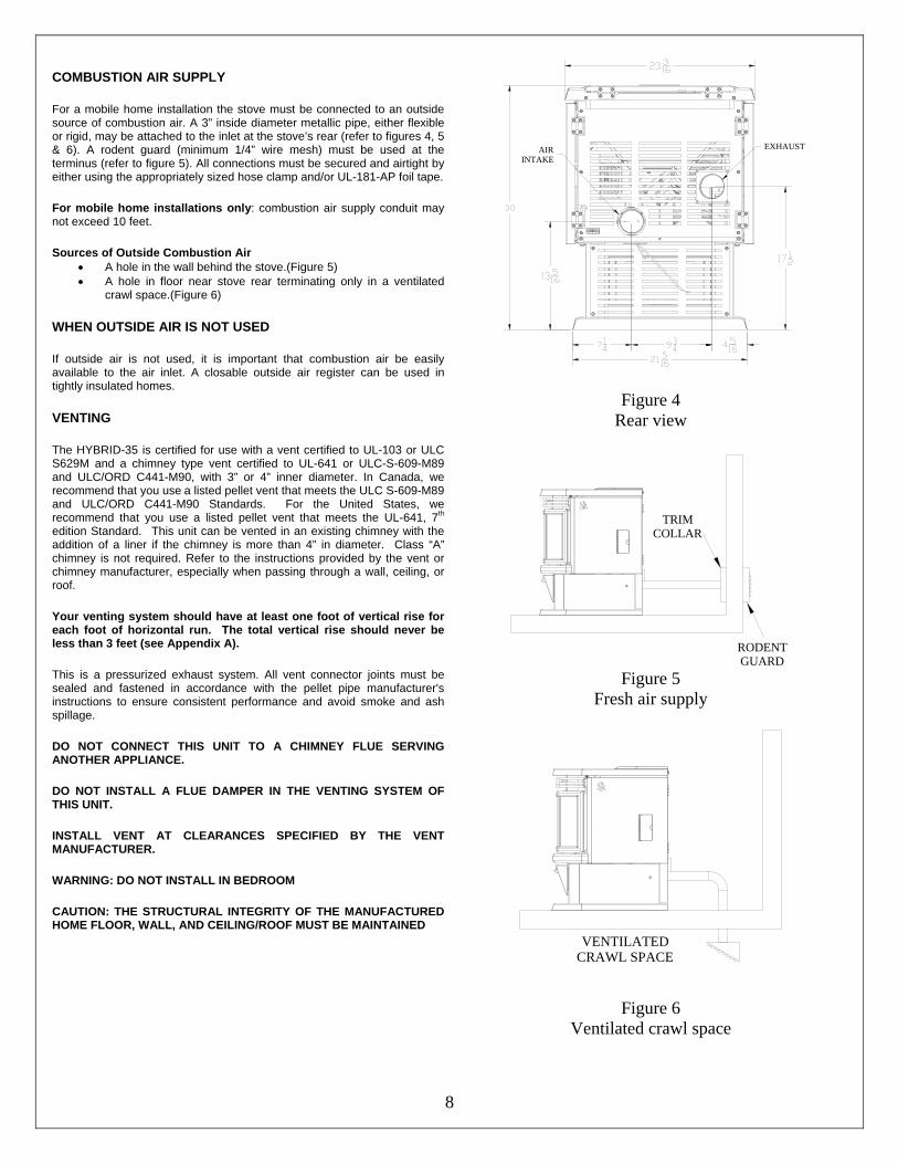
COMBUSTION AIR SUPPLY
For a mobile home installation the stove must be connected to an outside source of combustion air. A 3” inside diameter metallic pipe, either flexible or rigid, may be attached to the inlet at the stove’s rear (refer to figures 4, 5 & 6). A rodent guard (minimum 1/4” wire mesh) must be used at the terminus (refer to figure 5). All connections must be secured and airtight by either using the appropriately sized hose clamp and/or UL-181-AP foil tape.
For mobile home installations only: combustion air supply conduit may not exceed 10 feet.
Sources of Outside Combustion Air • A hole in the wall behind the stove.(Figure 5) • A hole in floor near stove rear terminating only in a ventilated
crawl space.(Figure 6)
WHEN OUTSIDE AIR IS NOT USED
If outside air is not used, it is important that combustion air be easily available to the air inlet. A closable outside air register can be used in tightly insulated homes.
VENTING
The HYBRID-35 is certified for use with a vent certified to UL-103 or ULC S629M and a chimney type vent certified to UL-641 or ULC-S-609-M89 and ULC/ORD C441-M90, with 3” or 4” inner diameter. In Canada, we recommend that you use a listed pellet vent that meets the ULC S-609-M89 and ULC/ORD C441-M90 Standards. For the United States, we recommend that you use a listed pellet vent that meets the UL-641, 7th edition Standard. This unit can be vented in an existing chimney with the addition of a liner if the chimney is more than 4” in diameter. Class “A” chimney is not required. Refer to the instructions provided by the vent or chimney manufacturer, especially when passing through a wall, ceiling, or roof.
Your venting system should have at least one foot of vertical rise for each foot of horizontal run. The total vertical rise should never be less than 3 feet (see Appendix A).
This is a pressurized exhaust system. All vent connector joints must be sealed and fastened in accordance with the pellet pipe manufacturer's instructions to ensure consistent performance and avoid smoke and ash spillage.
DO NOT CONNECT THIS UNIT TO A CHIMNEY FLUE SERVING ANOTHER APPLIANCE.
DO NOT INSTALL A FLUE DAMPER IN THE VENTING SYSTEM OF THIS UNIT.
INSTALL VENT AT CLEARANCES SPECIFIED BY THE VENT MANUFACTURER.
WARNING: DO NOT INSTALL IN BEDROOM
CAUTION: THE STRUCTURAL INTEGRITY OF THE MANUFACTURED HOME FLOOR, WALL, AND CEILING/ROOF MUST BE MAINTAINED
AIRINTAKE
EXHAUST
Figure 4 Rear view
TRIMCOLLAR
RODENTGUARD
Figure 5 Fresh air supply
VENTILATED CRAWL SPACE
Figure 6 Ventilated crawl space
9
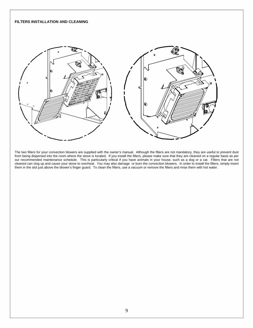
FILTERS INSTALLATION AND CLEANING
The two filters for your convection blowers are supplied with the owner’s manual. Although the filters are not mandatory, they are useful to prevent dust from being dispersed into the room where the stove is located. If you install the filters, please make sure that they are cleaned on a regular basis as per our recommended maintenance schedule. This is particularly critical if you have animals in your house, such as a dog or a cat. Filters that are not cleaned can clog up and cause your stove to overheat. You may also damage or burn the convection blowers. In order to install the filters, simply insert them in the slot just above the blower’s finger guard. To clean the filters, use a vacuum or remove the filters and rinse them with hot water.
10
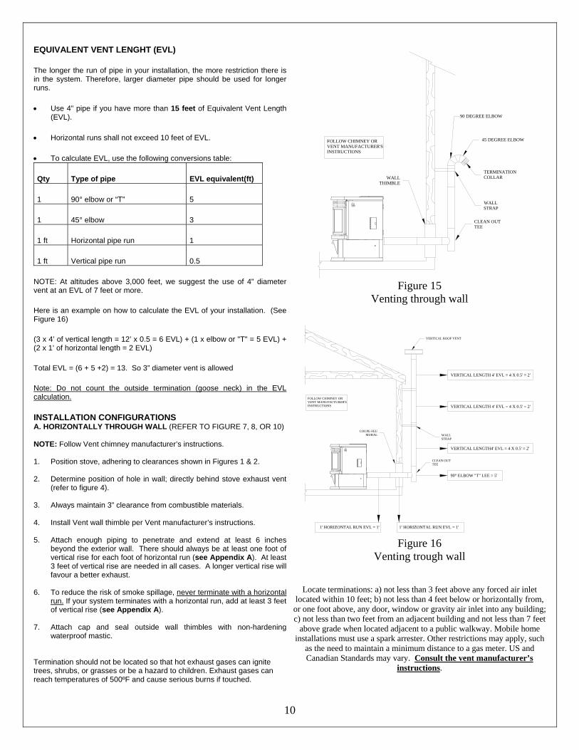
EQUIVALENT VENT LENGHT (EVL)
The longer the run of pipe in your installation, the more restriction there is in the system. Therefore, larger diameter pipe should be used for longer runs.
• Use 4” pipe if you have more than 15 feet of Equivalent Vent Length (EVL).
• Horizontal runs shall not exceed 10 feet of EVL.
• To calculate EVL, use the following conversions table:
Qty Type of pipe EVL equivalent(ft)
1 90° elbow or “T” 5
1 45° elbow 3
1 ft Horizontal pipe run 1
1 ft Vertical pipe run 0.5
NOTE: At altitudes above 3,000 feet, we suggest the use of 4” diameter vent at an EVL of 7 feet or more.
Here is an example on how to calculate the EVL of your installation. (See Figure 16)
(3 x 4’ of vertical length = 12’ x 0.5 = 6 EVL) + (1 x elbow or "T" = 5 EVL) + (2 x 1’ of horizontal length = 2 EVL)
Total EVL = (6 + 5 +2) = 13. So 3” diameter vent is allowed
Note: Do not count the outside termination (goose neck) in the EVL calculation.
INSTALLATION CONFIGURATIONS A. HORIZONTALLY THROUGH WALL (REFER TO FIGURE 7, 8, OR 10) NOTE: Follow Vent chimney manufacturer’s instructions. 1. Position stove, adhering to clearances shown in Figures 1 & 2. 2. Determine position of hole in wall; directly behind stove exhaust vent
(refer to figure 4). 3. Always maintain 3” clearance from combustible materials. 4. Install Vent wall thimble per Vent manufacturer’s instructions. 5. Attach enough piping to penetrate and extend at least 6 inches
beyond the exterior wall. There should always be at least one foot of vertical rise for each foot of horizontal run (see Appendix A). At least 3 feet of vertical rise are needed in all cases. A longer vertical rise will favour a better exhaust.
6. To reduce the risk of smoke spillage, never terminate with a horizontal
run. If your system terminates with a horizontal run, add at least 3 feet of vertical rise (see Appendix A).
7. Attach cap and seal outside wall thimbles with non-hardening
waterproof mastic. Termination should not be located so that hot exhaust gases can ignite trees, shrubs, or grasses or be a hazard to children. Exhaust gases can reach temperatures of 500ºF and cause serious burns if touched.
90 DEGREE ELBOW
45 DEGREE ELBOW
TERMINATION COLLAR
WALLSTRAP
FOLLOW CHIMNEY OR VENT MANUFACTURER'S INSTRUCTIONS
WALLTHIMBLE
CLEAN OUTTEE
Figure 15
Venting through wall
WALLSTRAP
CLEAN OUTTEE
VERTICAL ROOF VENT
1' HORIZONTAL RUN EVL = 1'
FOLLOW CHIMNEY OR VENT MANUFACTURER'S INSTRUCTIONS
1' HORIZONTAL RUN EVL = 1'
90° ELBOW "T" LEE = 5'
VERTICAL LENGTH 4' EVL = 4 X 0.5' = 2'
VERTICAL LENGTH 4' EVL = 4 X 0.5' = 2'
VERTICAL LENGTH4' EVL = 4 X 0.5' = 2'
COUPE-FEUMURAL
Figure 16
Venting trough wall
Locate terminations: a) not less than 3 feet above any forced air inlet
located within 10 feet; b) not less than 4 feet below or horizontally from, or one foot above, any door, window or gravity air inlet into any building; c) not less than two feet from an adjacent building and not less than 7 feet
above grade when located adjacent to a public walkway. Mobile home installations must use a spark arrester. Other restrictions may apply, such
as the need to maintain a minimum distance to a gas meter. US and Canadian Standards may vary. Consult the vent manufacturer’s
instructions.
11
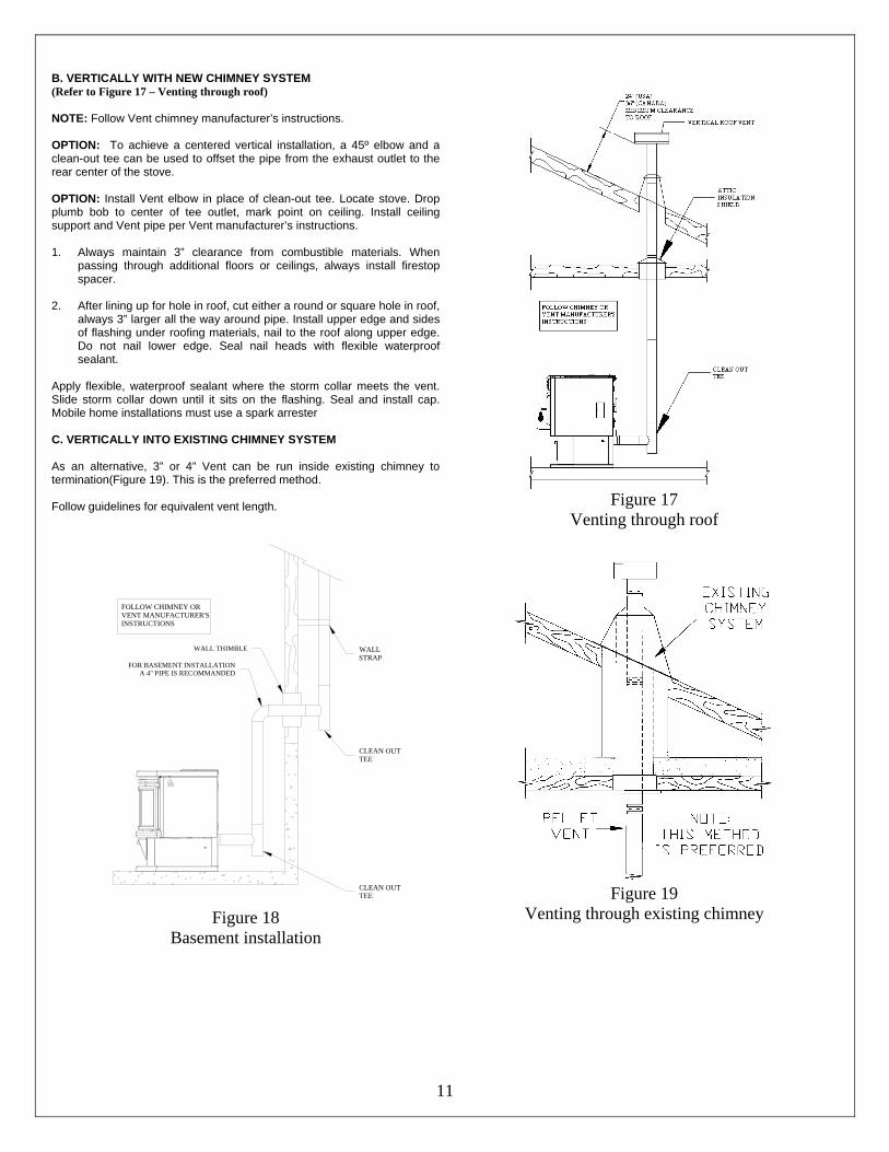
B. VERTICALLY WITH NEW CHIMNEY SYSTEM (Refer to Figure 17 – Venting through roof) NOTE: Follow Vent chimney manufacturer’s instructions. OPTION: To achieve a centered vertical installation, a 45º elbow and a clean-out tee can be used to offset the pipe from the exhaust outlet to the rear center of the stove. OPTION: Install Vent elbow in place of clean-out tee. Locate stove. Drop plumb bob to center of tee outlet, mark point on ceiling. Install ceiling support and Vent pipe per Vent manufacturer’s instructions. 1. Always maintain 3” clearance from combustible materials. When
passing through additional floors or ceilings, always install firestop spacer.
2. After lining up for hole in roof, cut either a round or square hole in roof,
always 3” larger all the way around pipe. Install upper edge and sides of flashing under roofing materials, nail to the roof along upper edge. Do not nail lower edge. Seal nail heads with flexible waterproof sealant.
Apply flexible, waterproof sealant where the storm collar meets the vent. Slide storm collar down until it sits on the flashing. Seal and install cap. Mobile home installations must use a spark arrester C. VERTICALLY INTO EXISTING CHIMNEY SYSTEM As an alternative, 3” or 4” Vent can be run inside existing chimney to termination(Figure 19). This is the preferred method. Follow guidelines for equivalent vent length.
Figure 17
Venting through roof
CLEAN OUTTEE
CLEAN OUTTEE
FOR BASEMENT INSTALLATIONA 4" PIPE IS RECOMMANDED
FOLLOW CHIMNEY OR VENT MANUFACTURER'S INSTRUCTIONS
WALLSTRAP
WALL THIMBLE
Figure 18
Basement installation
Figure 19
Venting through existing chimney
12
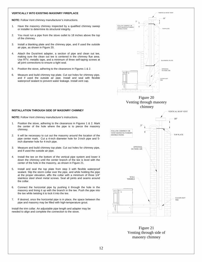
VERTICALLY INTO EXISTING MASONRY FIREPLACE NOTE: Follow Vent chimney manufacturer’s instructions. 1. Have the masonry chimney inspected by a qualified chimney sweep
or installer to determine its structural integrity. 2. You must run a pipe from the stove outlet to 18 inches above the top
of the chimney. 3. Install a blanking plate and the chimney pipe, and if used the outside
air pipe, as shown in Figure 20.
4. Attach the DuraVent adapter, a section of pipe and clean out tee, making sure the clean out tee is centered in the chimney flue area. Use RTV, metallic tape, and a minimum of three self-taping screws at all joint connections to ensure a tight seal.
5. Position the stove, adhering to the clearances in Figures 1 & 2. 6. Measure and build chimney top plate. Cut out holes for chimney pipe,
and if used the outside air pipe. Install and seal with flexible waterproof sealant to prevent water leakage. Install vent cap.
CLEAN OUTTEE
OPTIONALOUTSIDE AIR
BLANKING PLATE
FOLLOW CHIMNEY OR VENT MANUFACTURER'S INSTRUCTIONS
3"
TOP PLATE
VERTICAL ROOF VENT
18"
Figure 20
Venting through masonry chimney
INSTALLATION THROUGH SIDE OF MASONRY CHIMNEY NOTE: Follow Vent chimney manufacturer’s instructions. 1. Position the stove, adhering to the clearances in Figures 1 & 2. Mark
the center of the hole where the pipe is to pierce the masonry chimney.
2. It will be necessary to cut out the masonry around the location of the
pipe center mark. Cut a 4-inch diameter hole for 3-inch pipe and 5-inch diameter hole for 4-inch pipe.
3. Measure and build chimney top plate. Cut out holes for chimney pipe,
and if used the outside air pipe. 4. Install the tee on the bottom of the vertical pipe system and lower it
down the chimney until the center branch of the tee is level with the center of the hole in the masonry, as shown in Figure 21.
5. Install and seal the top plate from step 3 with flexible waterproof
sealant. Slip the storm collar over the pipe, and while holding the pipe at the proper elevation, affix the collar with a minimum of three 1/4” stainless steel sheet metal screws. Seal all joints and seams around the collar.
6. Connect the horizontal pipe by pushing it through the hole in the
masonry and lining it up with the branch in the tee. Push the pipe into the tee while twisting it to lock it into the tee.
7. If desired, once the horizontal pipe is in place, the space between the
pipe and masonry may be filled with high-temperature grout. Install the trim collar. An adjustable pipe length and adapter may be needed to align and complete the connection to the stove.
WALLTHIMBLE
CLEAN OUTTEE
FOLLOW CHIMNEY OR VENT MANUFACTURER'S INSTRUCTIONS
OPTIONALOUTSIDE AIR
3"
TOP PLATE
VERTICAL ROOF VENT
18"
Figure 21 Venting through side of
masonry chimney
13
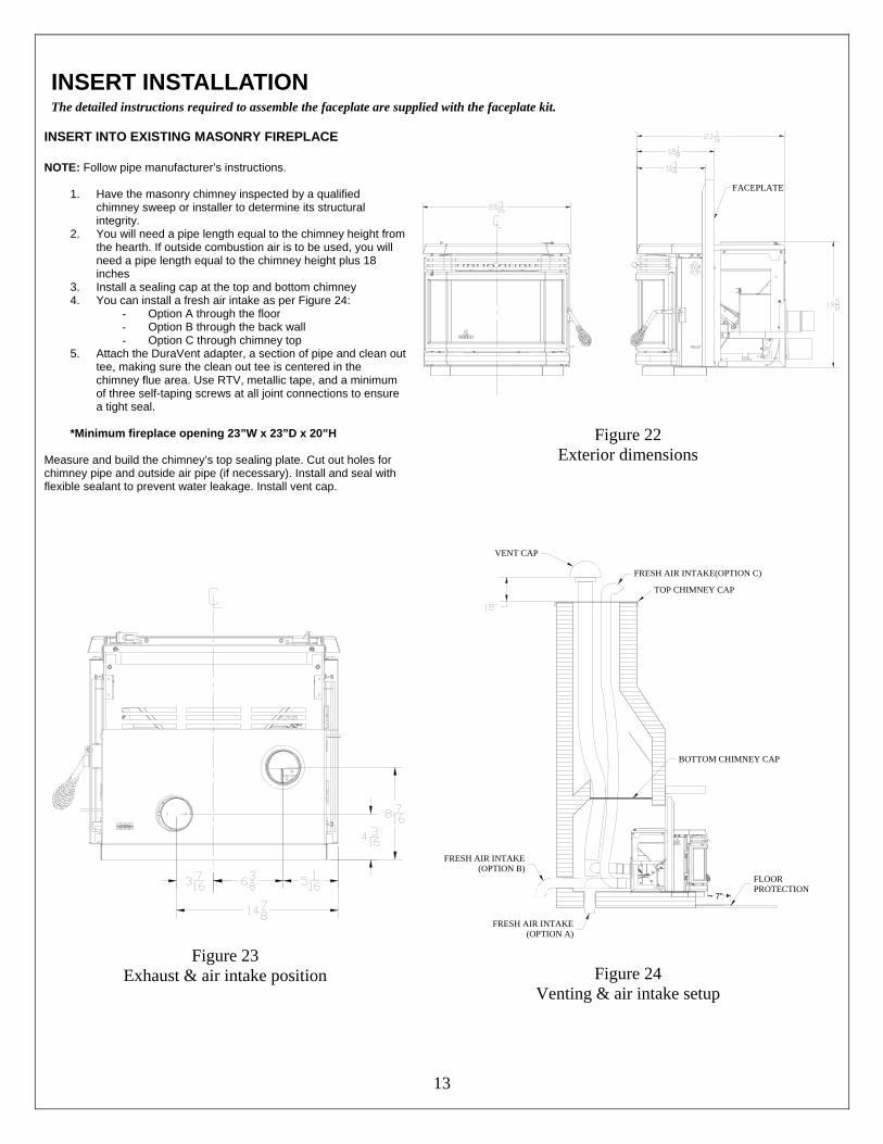
INSERT INSTALLATION The detailed instructions required to assemble the faceplate are supplied with the faceplate kit.
INSERT INTO EXISTING MASONRY FIREPLACE NOTE: Follow pipe manufacturer’s instructions.
1. Have the masonry chimney inspected by a qualified chimney sweep or installer to determine its structural integrity.
2. You will need a pipe length equal to the chimney height from the hearth. If outside combustion air is to be used, you will need a pipe length equal to the chimney height plus 18 inches
3. Install a sealing cap at the top and bottom chimney 4. You can install a fresh air intake as per Figure 24:
- Option A through the floor - Option B through the back wall - Option C through chimney top
5. Attach the DuraVent adapter, a section of pipe and clean out tee, making sure the clean out tee is centered in the chimney flue area. Use RTV, metallic tape, and a minimum of three self-taping screws at all joint connections to ensure a tight seal.
*Minimum fireplace opening 23”W x 23”D x 20”H
Measure and build the chimney’s top sealing plate. Cut out holes for chimney pipe and outside air pipe (if necessary). Install and seal with flexible sealant to prevent water leakage. Install vent cap.
FACEPLATE
Figure 22
Exterior dimensions
Figure 23
Exhaust & air intake position
7"
BOTTOM CHIMNEY CAP
TOP CHIMNEY CAP
VENT CAP
FLOORPROTECTION
FRESH AIR INTAKE(OPTION A)
FRESH AIR INTAKE(OPTION C)
FRESH AIR INTAKE(OPTION B)
Figure 24 Venting & air intake setup
14
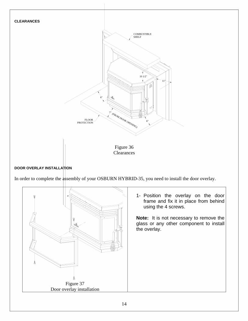
CLEARANCES
6"
6"
7" (FROM DOOR OPENING)
FLOORPROTECTION
COMBUSTIBLESHELF
11"
10 1/2"
Figure 36 Clearances
DOOR OVERLAY INSTALLATION In order to complete the assembly of your OSBURN HYBRID-35, you need to install the door overlay.
Figure 37
Door overlay installation
1- Position the overlay on the door
frame and fix it in place from behind using the 4 screws.
Note: It is not necessary to remove the glass or any other component to install the overlay.
15
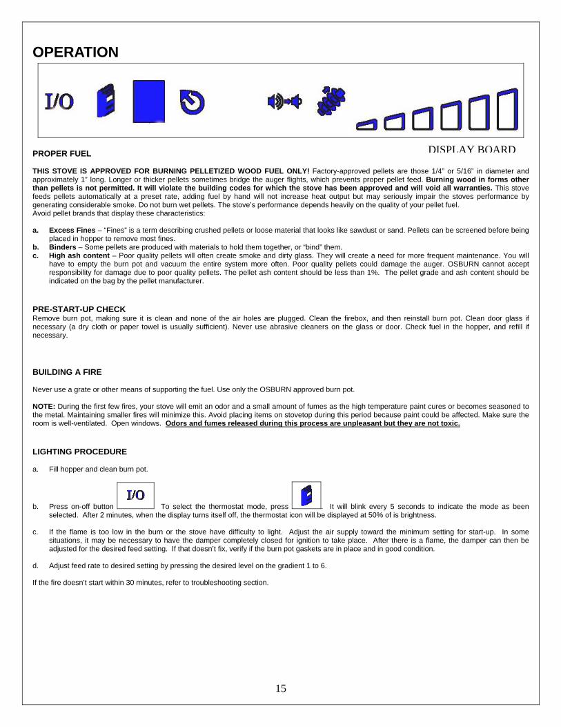
OPERATION
PROPER FUEL THIS STOVE IS APPROVED FOR BURNING PELLETIZED WOOD FUEL ONLY! Factory-approved pellets are those 1/4” or 5/16” in diameter and approximately 1” long. Longer or thicker pellets sometimes bridge the auger flights, which prevents proper pellet feed. Burning wood in forms other than pellets is not permitted. It will violate the building codes for which the stove has been approved and will void all warranties. This stove feeds pellets automatically at a preset rate, adding fuel by hand will not increase heat output but may seriously impair the stoves performance by generating considerable smoke. Do not burn wet pellets. The stove’s performance depends heavily on the quality of your pellet fuel. Avoid pellet brands that display these characteristics: a. Excess Fines – “Fines” is a term describing crushed pellets or loose material that looks like sawdust or sand. Pellets can be screened before being
placed in hopper to remove most fines. b. Binders – Some pellets are produced with materials to hold them together, or “bind” them. c. High ash content – Poor quality pellets will often create smoke and dirty glass. They will create a need for more frequent maintenance. You will
have to empty the burn pot and vacuum the entire system more often. Poor quality pellets could damage the auger. OSBURN cannot accept responsibility for damage due to poor quality pellets. The pellet ash content should be less than 1%. The pellet grade and ash content should be indicated on the bag by the pellet manufacturer.
PRE-START-UP CHECK Remove burn pot, making sure it is clean and none of the air holes are plugged. Clean the firebox, and then reinstall burn pot. Clean door glass if necessary (a dry cloth or paper towel is usually sufficient). Never use abrasive cleaners on the glass or door. Check fuel in the hopper, and refill if necessary.
BUILDING A FIRE Never use a grate or other means of supporting the fuel. Use only the OSBURN approved burn pot. NOTE: During the first few fires, your stove will emit an odor and a small amount of fumes as the high temperature paint cures or becomes seasoned to the metal. Maintaining smaller fires will minimize this. Avoid placing items on stovetop during this period because paint could be affected. Make sure the room is well-ventilated. Open windows. Odors and fumes released during this process are unpleasant but they are not toxic.
LIGHTING PROCEDURE a. Fill hopper and clean burn pot.
b. Press on-off button To select the thermostat mode, press . It will blink every 5 seconds to indicate the mode as been selected. After 2 minutes, when the display turns itself off, the thermostat icon will be displayed at 50% of is brightness.
c. If the flame is too low in the burn or the stove have difficulty to light. Adjust the air supply toward the minimum setting for start-up. In some
situations, it may be necessary to have the damper completely closed for ignition to take place. After there is a flame, the damper can then be adjusted for the desired feed setting. If that doesn’t fix, verify if the burn pot gaskets are in place and in good condition.
d. Adjust feed rate to desired setting by pressing the desired level on the gradient 1 to 6. If the fire doesn’t start within 30 minutes, refer to troubleshooting section.
DISPLAY BOARD
16
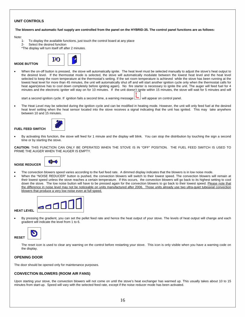
UNIT CONTROLS
The blowers and automatic fuel supply are controlled from the panel on the HYBRID-35. The control panel functions are as follows: Note:
1- To display the available functions, just touch the control board at any place 2- Select the desired function *The display will turn itself off after 2 minutes.
MODE BUTTON • When the on-off button is pressed, the stove will automatically ignite. The heat level must be selected manually to adjust the stove’s heat output to
the desired level. If the thermostat mode is selected, the stove will automatically modulate between the lowest heat level and the heat level selected to keep the room temperature at the thermostat’s setting. If the set room temperature is achieved while the stove has been running at the lowest heat level for more than 45 minutes, the unit will automatically shut off and will start another ignition cycle only when the thermostat calls for heat again(stove has to cool down completely before igniting again). No fire starter is necessary to ignite the unit. The auger will feed fuel for 4 minutes and the electronic igniter will stay on for 10 minutes. If the unit doesn’t ignite within 15 minutes, the stove will wait for 5 minutes and will
start a second ignition cycle. If ignition fails a second time, a warning message will appear on control panel. • The Heat Level may be selected during the ignition cycle and can be modified in heating mode. However, the unit will only feed fuel at the desired
heat level setting when the heat sensor located into the stove receives a signal indicating that the unit has ignited. This may take anywhere between 10 and 15 minutes.
FUEL FEED SWITCH • By activating this function, the stove will feed for 1 minute and the display will blink. You can stop the distribution by touching the sign a second
time or by starting the stove. CAUTION: THIS FUNCTION CAN ONLY BE OPERATED WHEN THE STOVE IS IN “OFF” POSITION. THE FUEL FEED SWITCH IS USED TO PRIME THE AUGER WHEN THE AUGER IS EMPTY.
NOISE REDUCER • The convection blowers speed varies according to the fuel feed rate. A dimmed display indicates that the blowers is in low noise mode. • When the “NOISE REDUCER” button is pushed, the convection blowers will switch to their lowest speed. The convection blowers will remain at
their lowest speed unless the stove reaches a certain temperature. If this occurs, the convection blowers will go back to its highest setting to cool down the stove. The low noise button will have to be pressed again for the convection blowers to go back to their lowest speed. Please note that the difference in noise level may not be noticeable on units manufactured after 2006. Those units already use two ultra-quiet tubeaxial convection blowers that produce a very low noise even at full speed.
HEAT LEVEL • By pressing the gradient, you can set the pellet feed rate and hence the heat output of your stove. The levels of heat output will change and each
gradient will indicate the level from 1 to 6.
RESET
The reset icon is used to clear any warning on the control before restarting your stove. This icon is only visible when you have a warning code on the display.
OPENING DOOR The door should be opened only for maintenance purposes.
CONVECTION BLOWERS (ROOM AIR FANS) Upon starting your stove, the convection blowers will not come on until the stove’s heat exchanger has warmed up. This usually takes about 10 to 15 minutes from start-up. Speed will vary with the selected feed rate, except if the noise reducer mode has been activated.
17
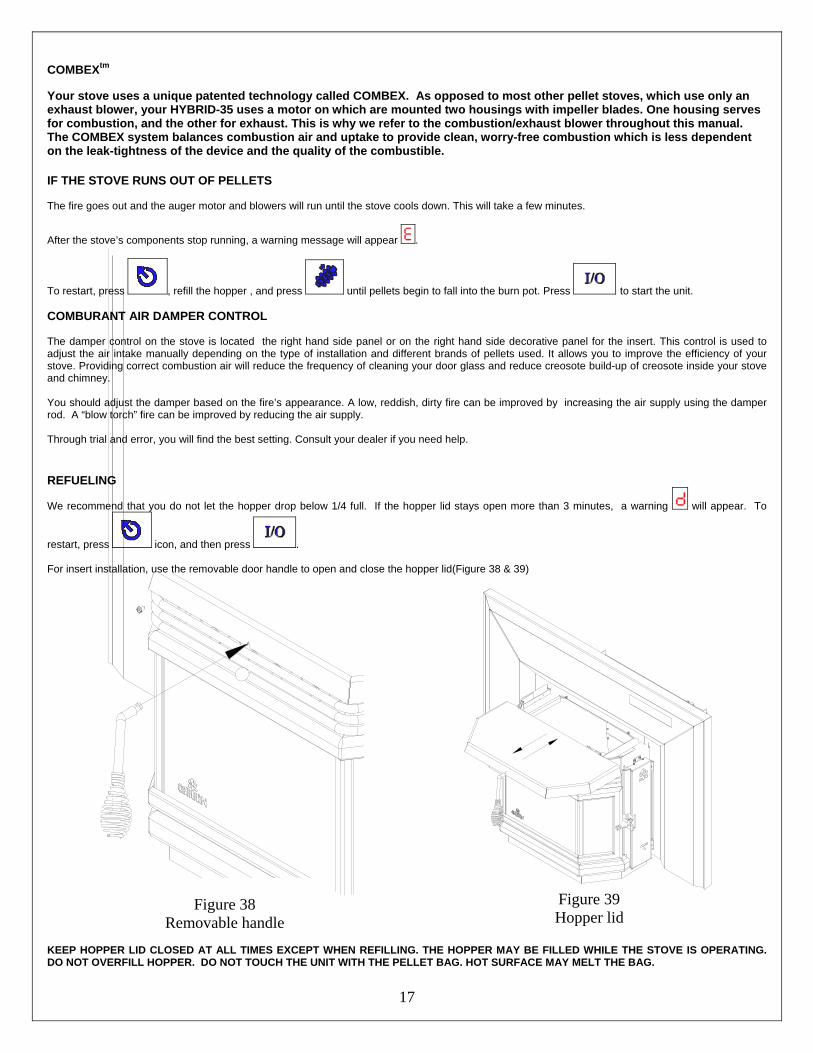
COMBEXtm Your stove uses a unique patented technology called COMBEX. As opposed to most other pellet stoves, which use only an exhaust blower, your HYBRID-35 uses a motor on which are mounted two housings with impeller blades. One housing serves for combustion, and the other for exhaust. This is why we refer to the combustion/exhaust blower throughout this manual. The COMBEX system balances combustion air and uptake to provide clean, worry-free combustion which is less dependent on the leak-tightness of the device and the quality of the combustible.
IF THE STOVE RUNS OUT OF PELLETS The fire goes out and the auger motor and blowers will run until the stove cools down. This will take a few minutes.
After the stove’s components stop running, a warning message will appear .
To restart, press , refill the hopper , and press until pellets begin to fall into the burn pot. Press to start the unit. COMBURANT AIR DAMPER CONTROL The damper control on the stove is located the right hand side panel or on the right hand side decorative panel for the insert. This control is used to adjust the air intake manually depending on the type of installation and different brands of pellets used. It allows you to improve the efficiency of your stove. Providing correct combustion air will reduce the frequency of cleaning your door glass and reduce creosote build-up of creosote inside your stove and chimney. You should adjust the damper based on the fire’s appearance. A low, reddish, dirty fire can be improved by increasing the air supply using the damper rod. A “blow torch” fire can be improved by reducing the air supply. Through trial and error, you will find the best setting. Consult your dealer if you need help.
REFUELING
We recommend that you do not let the hopper drop below 1/4 full. If the hopper lid stays open more than 3 minutes, a warning will appear. To
restart, press icon, and then press . For insert installation, use the removable door handle to open and close the hopper lid(Figure 38 & 39)
Figure 38 Removable handle
Figure 39 Hopper lid
KEEP HOPPER LID CLOSED AT ALL TIMES EXCEPT WHEN REFILLING. THE HOPPER MAY BE FILLED WHILE THE STOVE IS OPERATING. DO NOT OVERFILL HOPPER. DO NOT TOUCH THE UNIT WITH THE PELLET BAG. HOT SURFACE MAY MELT THE BAG.
18
SHUTDOWN PROCEDURE
Turning your OSBURN stove off is a matter of pressing on the control panel. The blowers will continue to operate until internal firebox temperatures have fallen to a preset level. The stove cannot restart before it has completely shut down.
SAFETY FEATURES
a. Your stove is equipped with a manual reset high temperature switch (also called heat sensor or heat switch). The switch has a reset button on its backside. Like a circuit breaker, once tripped, the reset button will have to be pushed before you can restart the stove. The high temperature switch protects the stove against overheating due to of an evacuation problem, a control board problem, a blower problem, or any other problem causing the unit to overheat. The manufacturer recommends that you contact your dealer if this occurs as it may hide a major problem. A service call may be required.
NOTE: If an overheating situation occurs, the high temperature switch (called the L-250 manual reset) will automatically shut down the auger
motor (fuel feed system) and a warning code will appear.
b. If the combustion blower fails, an air pressure switch will automatically shut down the auger and a warning message will appear. This safety feature is to prevent the unit from igniting or burning fuel when the combustion/exhaust blower has failed, therefore preventing combustion fumes from spilling into the room.
c. If the temperature in the auger rises beyond a certain acceptable level, two high temperature switches located under and above auger housing
will stop the fuel feed system and a warning will appear.
CODE BEFORE RESETING TO RESET H1, H2, H3 OR H4
Heat exchanger and/or exhaust system is/are clogged. Refer to the owner’s manual for maintenance procedures. Press simultaneously for 2 seconds and
icons. *** After 3 attempts, reset is no longer possible, call SBI technical support.
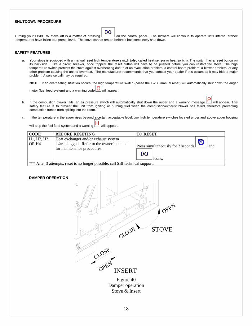
DAMPER OPERATION
OPENCLOSE
OPEN
CLOSE
INSERT
STOVE
Figure 40
Damper operation Stove & Insert
19
OPERATING THE STOVE USING A THERMOSTAT A thermostat will help you maintain a constant house temperature automatically. A millivolt or 24 Volt thermostat is required. A fixed wall mount or remote model can be used.
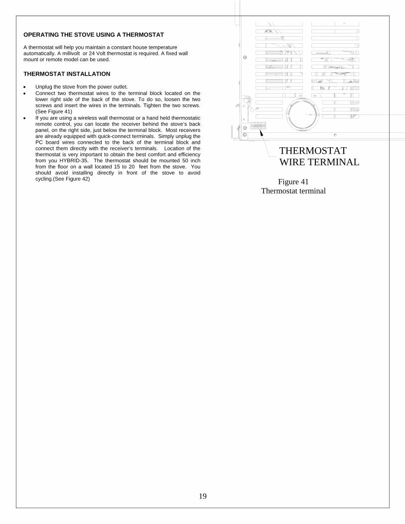
THERMOSTAT INSTALLATION • Unplug the stove from the power outlet. • Connect two thermostat wires to the terminal block located on the
lower right side of the back of the stove. To do so, loosen the two screws and insert the wires in the terminals. Tighten the two screws. (See Figure 41)
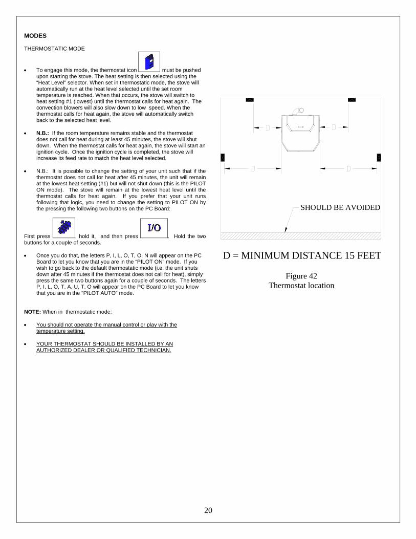
• If you are using a wireless wall thermostat or a hand held thermostatic remote control, you can locate the receiver behind the stove’s back panel, on the right side, just below the terminal block. Most receivers are already equipped with quick-connect terminals. Simply unplug the PC board wires connected to the back of the terminal block and connect them directly with the receiver’s terminals. Location of the thermostat is very important to obtain the best comfort and efficiency from you HYBRID-35. The thermostat should be mounted 50 inch from the floor on a wall located 15 to 20 feet from the stove. You should avoid installing directly in front of the stove to avoid cycling.(See Figure 42)
THERMOSTATWIRE TERMINAL
Figure 41
Thermostat terminal
20
MODES THERMOSTATIC MODE
• To engage this mode, the thermostat icon must be pushed upon starting the stove. The heat setting is then selected using the “Heat Level” selector. When set in thermostatic mode, the stove will automatically run at the heat level selected until the set room temperature is reached. When that occurs, the stove will switch to heat setting #1 (lowest) until the thermostat calls for heat again. The convection blowers will also slow down to low speed. When the thermostat calls for heat again, the stove will automatically switch back to the selected heat level.
• N.B.: If the room temperature remains stable and the thermostat
does not call for heat during at least 45 minutes, the stove will shut down. When the thermostat calls for heat again, the stove will start an ignition cycle. Once the ignition cycle is completed, the stove will increase its feed rate to match the heat level selected.
• N.B.: It is possible to change the setting of your unit such that if the
thermostat does not call for heat after 45 minutes, the unit will remain at the lowest heat setting (#1) but will not shut down (this is the PILOT ON mode). The stove will remain at the lowest heat level until the thermostat calls for heat again. If you prefer that your unit runs following that logic, you need to change the setting to PILOT ON by the pressing the following two buttons on the PC Board:
First press , hold it, and then press . Hold the two buttons for a couple of seconds. • Once you do that, the letters P, I, L, O, T, O, N will appear on the PC
Board to let you know that you are in the “PILOT ON” mode. If you wish to go back to the default thermostatic mode (i.e. the unit shuts down after 45 minutes if the thermostat does not call for heat), simply press the same two buttons again for a couple of seconds. The letters P, I, L, O, T, A, U, T, O will appear on the PC Board to let you know that you are in the “PILOT AUTO” mode.
NOTE: When in thermostatic mode: • You should not operate the manual control or play with the
temperature setting. • YOUR THERMOSTAT SHOULD BE INSTALLED BY AN
AUTHORIZED DEALER OR QUALIFIED TECHNICIAN.
D = MINIMUM DISTANCE 15 FEET
SHOULD BE AVOIDED
Figure 42 Thermostat location
21
OPERATING SAFETY PRECAUTIONS
PLEASE READ THIS! a. If you notice a smoldering fire (burnpot full but no visible flame) AND a heavy smoke buildup in firebox,
immediately TURN OFF the stove, but DO NOT unplug it. Do not open the door, change the damper setting or tamper with any controls on the stove. Wait until smoke inside the firebox clears and blowers shut down. Do as instructed in “PRE-START-UP CHECK” and “LIGHTHING PROCEDURE”, then attempt to restart the fire. If the problem persists, contact your dealer. Please note that smoke build-up during ignition may occur. Smoke can accumulate in the firebox for a few seconds just before the igniter is hot enough to fire-up the pellets in the burn pot. This is normal. As soon there is fire in the burn pot, smoke will disappear.
b. DO NOT STORE OR USE FLAMMABLE LIQUIDS, ESPECIALLY GASOLINE, IN THE VICINITY OF YOUR
OSBURN STOVE. NEVER USE A GAS OR PROPANE TORCH, GASOLINE, GASOLINE-TYPE LANTERN FUEL, KEROSENE, CHARCOAL LIGHTER FLUID OR SIMILAR FLUIDS TO START OR “FRESHEN UP” A FIRE IN THIS HEATER.
c. WARNING: DO NOT OVERFIRE THIS STOVE. This may cause serious damage to your stove and void your
warranty. It also may create a fire hazard in your home. IF ANY EXTERNAL PART OF THE UNIT BEGINS TO
GLOW, YOU ARE OVERFIRING. Immediately press on the control panel. DO NOT UNPLUG YOUR STOVE. If you leave your house and your stove is not connected to a thermostat or a fresh air supply, do not leave it at the maximum setting. If the ambient air becomes to hot, the stove may overheat and the thermal protection on the combustion/exhaust motor may be activated, causing the motor to stop.
d. KEEP ALL HOUSEHOLD COMBUSTIBLE MATERIALS, SUCH AS FURNITURE, DRAPES, TOYS, ETC. AT
LEAST THREE FEET AWAY FROM THE STOVE. e. Always maintain proper ventilation. It is important that sufficient oxygen be supplied to the fire for optimal combustion.
Modern houses are often so well insulated that it may become necessary to open a window slightly or install an outside air vent to provide sufficient combustion air.
f. Since heating with solid fuel is potentially hazardous, even with a well built and thoroughly tested stove, it would be
wise to install strategically placed smoke detectors and have a fire extinguisher in a convenient location, near an exit. g. Do not open the stove door when operating unless necessary. This will create a dirty, inefficient burn and could allow
smoke spillage or sparks to escape. h. Stove must not be operated by young children or someone unfamiliar with stove’s operation. i. Do not service or clean this appliance without disconnecting the power cord. j. Do not abuse the door glass by striking, slamming or similar trauma. Do not operate the stove with the glass removed,
cracked or broken. k. High ambient temperature in summer time may cause the heat sensors on the stove to activate the blowers,
disconnect the stove when not used for extended periods.
22
MAINTENANCE FAILURE TO CLEAN AND MAINTAIN THIS UNIT AS INDICATED CAN RESULT IN POOR PERFORMANCE AND SAFETY HAZARDS. NEVER CLEAN WHEN HOT. NOTE: Inspect burn pot periodically to see that holes have not become plugged. If so, clean thoroughly.
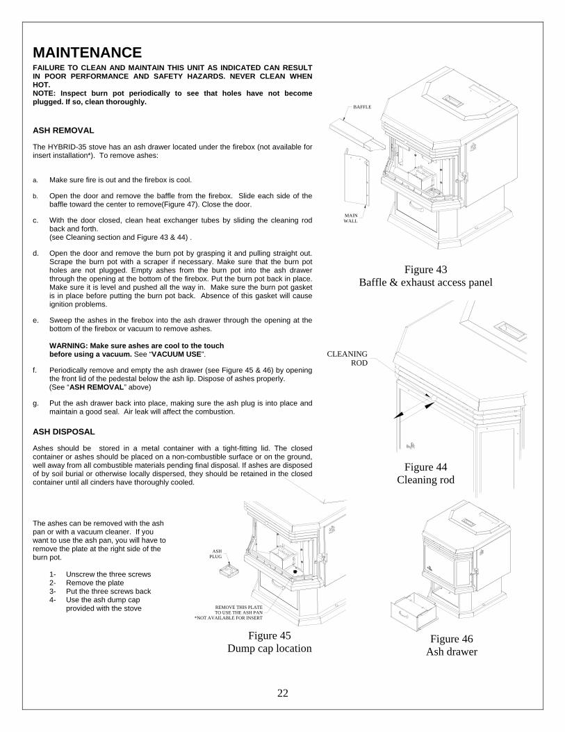
ASH REMOVAL The HYBRID-35 stove has an ash drawer located under the firebox (not available for insert installation*). To remove ashes: a. Make sure fire is out and the firebox is cool. b. Open the door and remove the baffle from the firebox. Slide each side of the
baffle toward the center to remove(Figure 47). Close the door. c. With the door closed, clean heat exchanger tubes by sliding the cleaning rod
back and forth. (see Cleaning section and Figure 43 & 44) .
d. Open the door and remove the burn pot by grasping it and pulling straight out.
Scrape the burn pot with a scraper if necessary. Make sure that the burn pot holes are not plugged. Empty ashes from the burn pot into the ash drawer through the opening at the bottom of the firebox. Put the burn pot back in place. Make sure it is level and pushed all the way in. Make sure the burn pot gasket is in place before putting the burn pot back. Absence of this gasket will cause ignition problems.
e. Sweep the ashes in the firebox into the ash drawer through the opening at the
bottom of the firebox or vacuum to remove ashes.
WARNING: Make sure ashes are cool to the touch before using a vacuum. See “VACUUM USE”.
f. Periodically remove and empty the ash drawer (see Figure 45 & 46) by opening
the front lid of the pedestal below the ash lip. Dispose of ashes properly. (See “ASH REMOVAL” above) g. Put the ash drawer back into place, making sure the ash plug is into place and
maintain a good seal. Air leak will affect the combustion.
ASH DISPOSAL Ashes should be stored in a metal container with a tight-fitting lid. The closed container or ashes should be placed on a non-combustible surface or on the ground, well away from all combustible materials pending final disposal. If ashes are disposed of by soil burial or otherwise locally dispersed, they should be retained in the closed container until all cinders have thoroughly cooled.
BAFFLE
MAINWALL
Figure 43 Baffle & exhaust access panel
CLEANINGROD
Figure 44 Cleaning rod
The ashes can be removed with the ash pan or with a vacuum cleaner. If you want to use the ash pan, you will have to remove the plate at the right side of the burn pot.
1- Unscrew the three screws 2- Remove the plate 3- Put the three screws back 4- Use the ash dump cap
provided with the stove
ASHPLUG
REMOVE THIS PLATETO USE THE ASH PAN
*NOT AVAILABLE FOR INSERT
Figure 45
Dump cap location
Figure 46
Ash drawer
23
VACCUM USE If a vacuum is used to clean your stove, we suggest using a vacuum designed for ashes. Some regular vacuums and shop vacs leak ash into the room. Your vacuum or shop vac may have a special filter or bag available to eliminate this leakage.
CLEANING
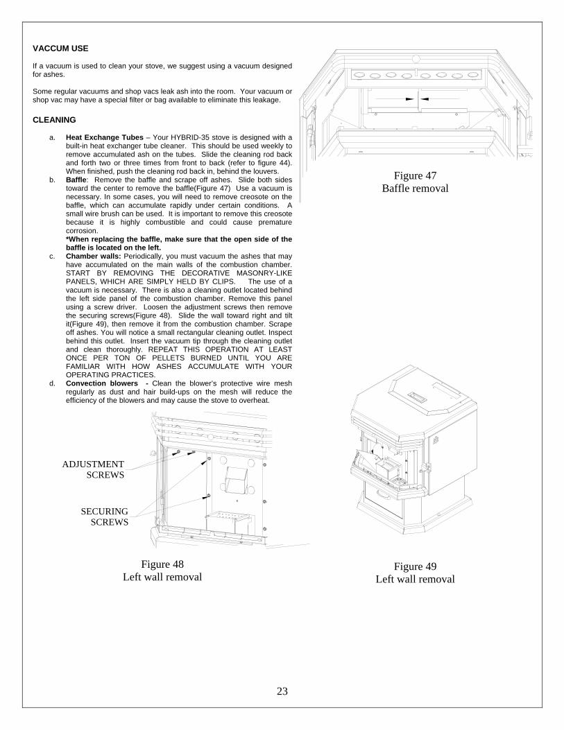
a. Heat Exchange Tubes – Your HYBRID-35 stove is designed with a built-in heat exchanger tube cleaner. This should be used weekly to remove accumulated ash on the tubes. Slide the cleaning rod back and forth two or three times from front to back (refer to figure 44). When finished, push the cleaning rod back in, behind the louvers.
b. Baffle: Remove the baffle and scrape off ashes. Slide both sides toward the center to remove the baffle(Figure 47) Use a vacuum is necessary. In some cases, you will need to remove creosote on the baffle, which can accumulate rapidly under certain conditions. A small wire brush can be used. It is important to remove this creosote because it is highly combustible and could cause premature corrosion. *When replacing the baffle, make sure that the open side of the baffle is located on the left.
c. Chamber walls: Periodically, you must vacuum the ashes that may have accumulated on the main walls of the combustion chamber. START BY REMOVING THE DECORATIVE MASONRY-LIKE PANELS, WHICH ARE SIMPLY HELD BY CLIPS. The use of a vacuum is necessary. There is also a cleaning outlet located behind the left side panel of the combustion chamber. Remove this panel using a screw driver. Loosen the adjustment screws then remove the securing screws(Figure 48). Slide the wall toward right and tilt it(Figure 49), then remove it from the combustion chamber. Scrape off ashes. You will notice a small rectangular cleaning outlet. Inspect behind this outlet. Insert the vacuum tip through the cleaning outlet and clean thoroughly. REPEAT THIS OPERATION AT LEAST ONCE PER TON OF PELLETS BURNED UNTIL YOU ARE FAMILIAR WITH HOW ASHES ACCUMULATE WITH YOUR OPERATING PRACTICES.
d. Convection blowers - Clean the blower’s protective wire mesh regularly as dust and hair build-ups on the mesh will reduce the efficiency of the blowers and may cause the stove to overheat.
SECURINGSCREWS
ADJUSTMENTSCREWS
Figure 48 Left wall removal
Figure 47
Baffle removal
Figure 49 Left wall removal
24
BLOWERS AND PRESSURE SWITCH PROBE
DANGER: RISK OF ELECTRIC SHOCK. DISCONNECT POWER BEFORE SERVICING UNIT.
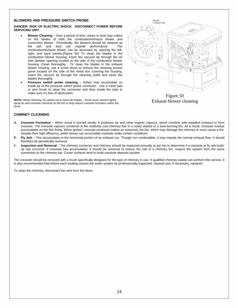
• Blower Cleaning – Over a period of time, ashes or dust may collect on the blades of both the combustion/exhaust blower and convection blower. Periodically, the blowers should be cleaned as the ash and dust can impede performance. The combustion/exhaust blower can be accessed by opening the left, right, and back panels.(Figure 50) To clean the blades in the combustion blower housing, insert the vacuum tip through the air inlet damper opening located on the side of the combustion blower housing. Clean thoroughly. To clean the blades in the exhaust blower housing, use a screw driver to remove the cleaning access panel located on the side of the metal box covering the housing. Insert the vacuum tip through the cleaning outlet and clean the blades thoroughly.
• Pressure switch probe cleaning – Ashes may accumulate on inside tip of the pressure switch probe connector. Use a mesh pad or wire brush to clean the connector and blow inside the tube to make sure it’s free of obstruction.
NOTE: When cleaning, be careful not to bend fan blades. Some stove owners lightly spray an anti-creosote chemical on the fire to help reduce creosote formation within the stove.
PROBECONNECTOR
Figure 50 Exhaust blower cleaning
CHIMNEY CLEANING a. Creosote Formation – When wood is burned slowly, it produces tar and other organic vapours, which combine with expelled moisture to form
creosote. The creosote vapours condense in the relatively cool chimney flue in a newly started or a slow-burning fire. As a result, creosote residue accumulates on the flue lining. When ignited, creosote produced makes an extremely hot fire, which may damage the chimney or even cause a fire. Despite their high efficiency, pellet stoves can accumulate creosote under certain conditions.
b. Fly Ash – This accumulates in the horizontal portion of an exhaust run. Though non-combustible, it may impede the normal exhaust flow. It should therefore be periodically removed.
c. Inspection and Removal – The chimney connector and chimney should be inspected annually or per ton to determine if a creosote or fly ash build-up has occurred. If creosote has accumulated, it should be removed to reduce the risk of a chimney fire. Inspect the system from the stove connection to the chimney top. Cooler surfaces tend to build creosote deposits quicker.
The creosote should be removed with a brush specifically designed for the type of chimney in use. A qualified chimney sweep can perform this service. It is also recommended that before each heating season the entire system be professionally inspected, cleaned and, if necessary, repaired. To clean the chimney, disconnect the vent from the stove.
25
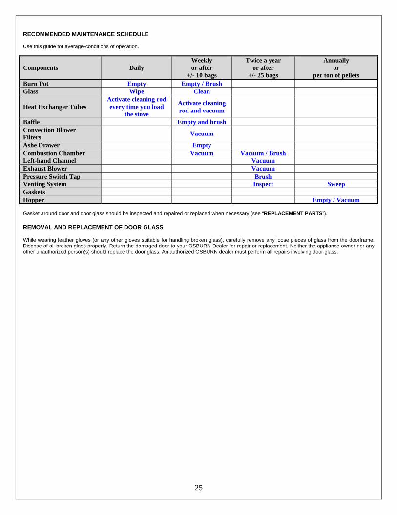
RECOMMENDED MAINTENANCE SCHEDULE Use this guide for average-conditions of operation.
Components Daily Weekly or after
+/- 10 bags
Twice a year or after
+/- 25 bags
Annually or
per ton of pellets Burn Pot Empty Empty / Brush Glass Wipe Clean
Heat Exchanger Tubes Activate cleaning rod every time you load
the stove
Activate cleaning rod and vacuum
Baffle Empty and brush Convection Blower Filters Vacuum
Ashe Drawer Empty Combustion Chamber Vacuum Vacuum / Brush Left-hand Channel Vacuum Exhaust Blower Vacuum Pressure Switch Tap Brush Venting System Inspect Sweep Gaskets Inspect Hopper Empty / Vacuum Gasket around door and door glass should be inspected and repaired or replaced when necessary (see “REPLACEMENT PARTS”).
REMOVAL AND REPLACEMENT OF DOOR GLASS While wearing leather gloves (or any other gloves suitable for handling broken glass), carefully remove any loose pieces of glass from the doorframe. Dispose of all broken glass properly. Return the damaged door to your OSBURN Dealer for repair or replacement. Neither the appliance owner nor any other unauthorized person(s) should replace the door glass. An authorized OSBURN dealer must perform all repairs involving door glass.
26
TROUBLESHOOTING When your stove acts abnormally, the first reaction is to get help. This guide may save you time and money by enabling you to resolve simple problems yourself. Problems can be caused by: 1) poor fuel; 2) poor operation or maintenance; 3) poor installation; 4) component failure; 5) factory defect. You can usually solve problems related to 1 and 2. Your dealer can solve problems related to 3, 4 and 5. Refer to ELECTRICAL DIAGRAM and REPLACEMENT PARTS section to help identify and locate stove parts. Should you need to contact your dealer or the manufacturer, please photocopy and fill out the form in Appendix B. Try to answer as many questions as you can. Have it handy when you call. This will help you obtain a much faster service.
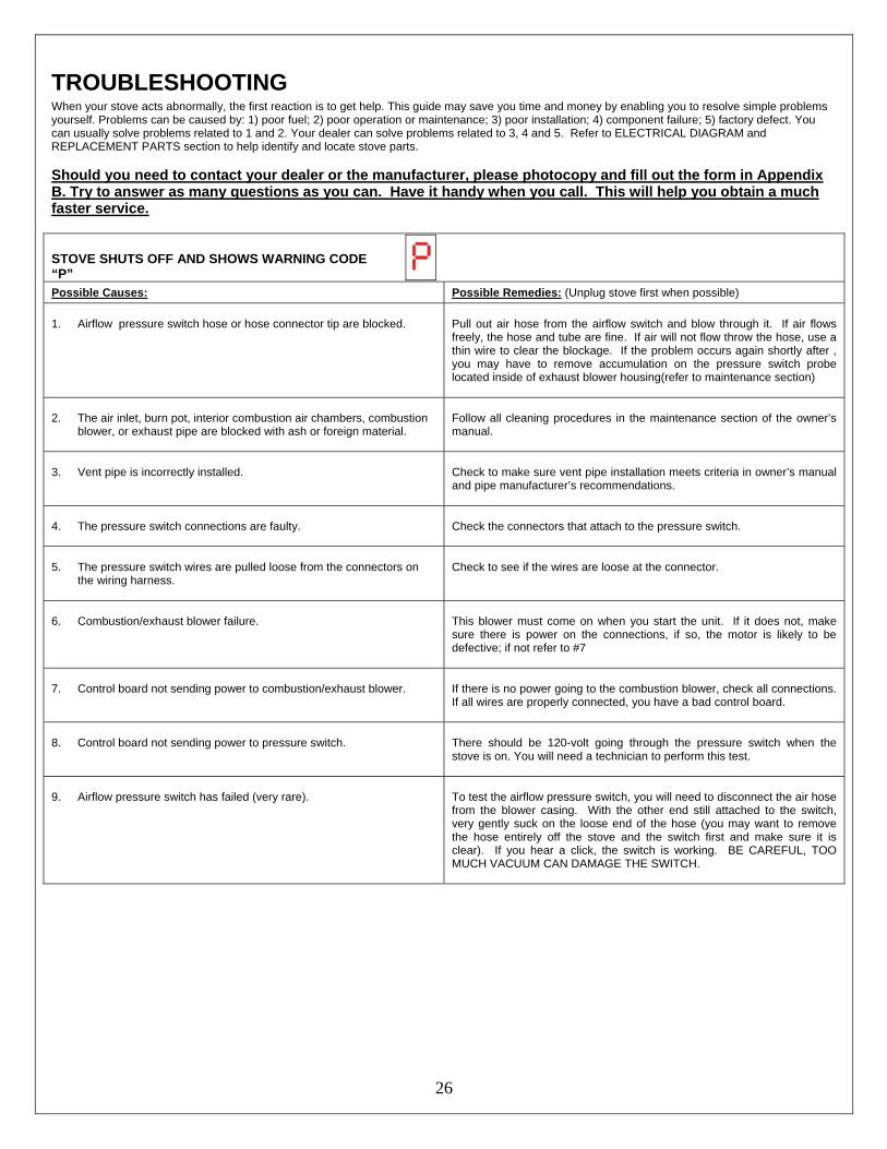
STOVE SHUTS OFF AND SHOWS WARNING CODE “P”
Possible Causes: Possible Remedies: (Unplug stove first when possible) 1. Airflow pressure switch hose or hose connector tip are blocked.
Pull out air hose from the airflow switch and blow through it. If air flows freely, the hose and tube are fine. If air will not flow throw the hose, use a thin wire to clear the blockage. If the problem occurs again shortly after , you may have to remove accumulation on the pressure switch probe located inside of exhaust blower housing(refer to maintenance section)
2. The air inlet, burn pot, interior combustion air chambers, combustion
blower, or exhaust pipe are blocked with ash or foreign material.
Follow all cleaning procedures in the maintenance section of the owner’s manual.
3. Vent pipe is incorrectly installed.
Check to make sure vent pipe installation meets criteria in owner’s manual and pipe manufacturer’s recommendations.
4. The pressure switch connections are faulty.
Check the connectors that attach to the pressure switch.
5. The pressure switch wires are pulled loose from the connectors on
the wiring harness.
Check to see if the wires are loose at the connector.
6. Combustion/exhaust blower failure.
This blower must come on when you start the unit. If it does not, make sure there is power on the connections, if so, the motor is likely to be defective; if not refer to #7
7. Control board not sending power to combustion/exhaust blower.
If there is no power going to the combustion blower, check all connections. If all wires are properly connected, you have a bad control board.
8. Control board not sending power to pressure switch.
There should be 120-volt going through the pressure switch when the stove is on. You will need a technician to perform this test.
9. Airflow pressure switch has failed (very rare).
To test the airflow pressure switch, you will need to disconnect the air hose from the blower casing. With the other end still attached to the switch, very gently suck on the loose end of the hose (you may want to remove the hose entirely off the stove and the switch first and make sure it is clear). If you hear a click, the switch is working. BE CAREFUL, TOO MUCH VACUUM CAN DAMAGE THE SWITCH.
27
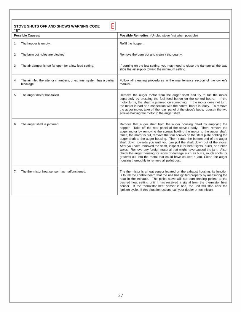
STOVE SHUTS OFF AND SHOWS WARNING CODE “E”
Possible Causes: Possible Remedies: (Unplug stove first when possible) 1. The hopper is empty.
Refill the hopper.
2. The burn pot holes are blocked.
Remove the burn pot and clean it thoroughly.
3. The air damper is too far open for a low feed setting.
If burning on the low setting, you may need to close the damper all the way slide the air supply toward the minimum setting.
4. The air inlet, the interior chambers, or exhaust system has a partial
blockage.
Follow all cleaning procedures in the maintenance section of the owner’s manual.
5. The auger motor has failed.
Remove the auger motor from the auger shaft and try to run the motor separately by pressing the fuel feed button on the control board. If the motor turns, the shaft is jammed on something. If the motor does not turn, the motor is bad or a connection with the control board is faulty. To remove the auger motor, take off the rear panel of the stove’s body. Loosen the two screws holding the motor to the auger shaft.
6. The auger shaft is jammed.
Remove that auger shaft from the auger housing. Start by emptying the hopper. Take off the rear panel of the stove’s body. Then, remove the auger motor by removing the screws holding the motor to the auger shaft. Once, the motor is out, remove the four screws on the steel plate holding the auger shaft to the auger housing. Then, rotate the bottom end of the auger shaft down towards you until you can pull the shaft down out of the stove. After you have removed the shaft, inspect it for bent flights, burrs, or broken welds. Remove any foreign material that might have caused the jam. Also, check the auger housing for signs of damage such as burrs, rough spots, or grooves cut into the metal that could have caused a jam. Clean the auger housing thoroughly to remove all pellet dust.
7. The thermistor heat sensor has malfunctioned.
The thermistor is a heat sensor located on the exhaust housing. Its function is to tell the control board that the unit has ignited properly by measuring the heat in the exhaust. The pellet stove will not start feeding pellets at the desired heat setting until it has received a signal from the thermistor heat sensor. If the thermistor heat sensor is bad, the unit will stop after the ignition cycle. If this situation occurs, call your dealer or technician.
28
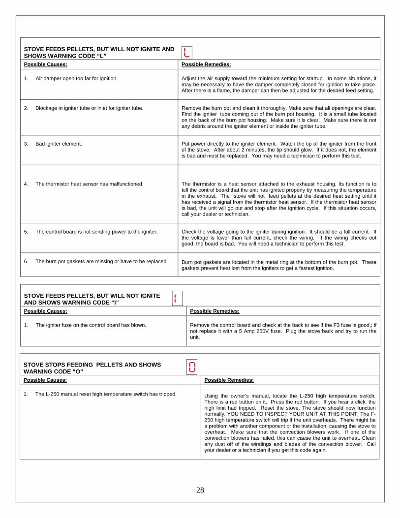
STOVE FEEDS PELLETS, BUT WILL NOT IGNITE AND SHOWS WARNING CODE “L”
Possible Causes: Possible Remedies: 1. Air damper open too far for ignition.
Adjust the air supply toward the minimum setting for startup. In some situations, it may be necessary to have the damper completely closed for ignition to take place. After there is a flame, the damper can then be adjusted for the desired feed setting.
2. Blockage in igniter tube or inlet for igniter tube.
Remove the burn pot and clean it thoroughly. Make sure that all openings are clear. Find the igniter tube coming out of the burn pot housing. It is a small tube located on the back of the burn pot housing. Make sure it is clear. Make sure there is not any debris around the igniter element or inside the igniter tube.
3. Bad igniter element.
Put power directly to the igniter element. Watch the tip of the igniter from the front of the stove. After about 2 minutes, the tip should glow. If it does not, the element is bad and must be replaced. You may need a technician to perform this test.
4. The thermistor heat sensor has malfunctioned.
The thermistor is a heat sensor attached to the exhaust housing. Its function is to tell the control board that the unit has ignited properly by measuring the temperature in the exhaust. The stove will not feed pellets at the desired heat setting until it has received a signal from the thermistor heat sensor. If the thermistor heat sensor is bad, the unit will go out and stop after the ignition cycle. If this situation occurs, call your dealer or technician.
5. The control board is not sending power to the igniter.
Check the voltage going to the igniter during ignition. It should be a full current. If the voltage is lower than full current, check the wiring. If the wiring checks out good, the board is bad. You will need a technician to perform this test.
6. The burn pot gaskets are missing or have to be replaced
Burn pot gaskets are located in the metal ring at the bottom of the burn pot. These gaskets prevent heat lost from the igniters to get a fastest ignition.
STOVE FEEDS PELLETS, BUT WILL NOT IGNITE AND SHOWS WARNING CODE “I”
Possible Causes: Possible Remedies: 1. The igniter fuse on the control board has blown.
Remove the control board and check at the back to see if the F3 fuse is good,; if not replace it with a 5 Amp 250V fuse. Plug the stove back and try to run the unit.
STOVE STOPS FEEDING PELLETS AND SHOWS WARNING CODE “O”
Possible Causes: Possible Remedies: 1. The L-250 manual reset high temperature switch has tripped. Using the owner’s manual, locate the L-250 high temperature switch.
There is a red button on it. Press the red button. If you hear a click, the high limit had tripped. Reset the stove. The stove should now function normally. YOU NEED TO INSPECT YOUR UNIT AT THIS POINT. The F-250 high temperature switch will trip if the unit overheats. There might be a problem with another component or the installation, causing the stove to overheat. Make sure that the convection blowers work. If one of the convection blowers has failed, this can cause the unit to overheat. Clean any dust off of the windings and blades of the convection blower. Call your dealer or a technician if you get this code again.
29
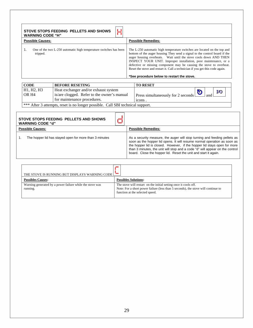
STOVE STOPS FEEDING PELLETS AND SHOWS WARNING CODE “H”
Possible Causes: Possible Remedies: 1. One of the two L-250 automatic high temperature switches has been
tripped.
The L-250 automatic high temperature switches are located on the top and bottom of the auger housing They send a signal to the control board if the auger housing overheats. Wait until the stove cools down AND THEN INSPECT YOUR UNIT. Improper installation, poor maintenance, or a defective or missing component may be causing the stove to overheat. Reset the stove and restart it. Call a technician if you get this code again. *See procedure below to restart the stove.
CODE BEFORE RESETING TO RESET H1, H2, H3 OR H4
Heat exchanger and/or exhaust system is/are clogged. Refer to the owner’s manual for maintenance procedures.
Press simultaneously for 2 seconds and icons .
*** After 3 attempts, reset is no longer possible. Call SBI technical support.
STOVE STOPS FEEDING PELLETS AND SHOWS WARNING CODE “d”
Possible Causes: Possible Remedies: 1. The hopper lid has stayed open for more than 3 minutes
As a security measure, the auger will stop turning and feeding pellets as soon as the hopper lid opens. It will resume normal operation as soon as the hopper lid is closed. However, if the hopper lid stays open for more than 3 minutes, the unit will stop and a code “d” will appear on the control board. Close the hopper lid. Reset the unit and start it again.
THE STOVE IS RUNNING BUT DISPLAYS WARNING CODE Possibles Causes: Possibles Solutions: Warning generated by a power failure while the stove was running.
The stove will restart on the initial setting once it cools off. Note: For a short power failure (less than 5 seconds), the stove will continue to function at the selected speed.
30
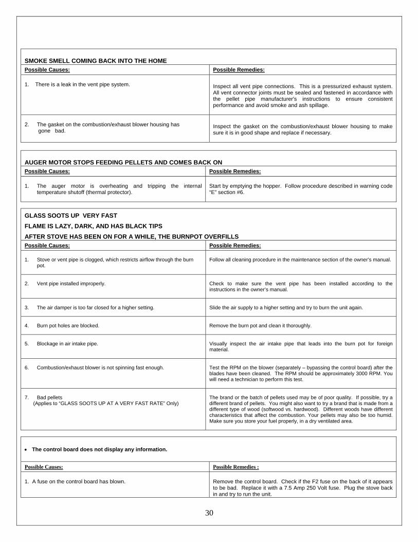
SMOKE SMELL COMING BACK INTO THE HOME Possible Causes: Possible Remedies: 1. There is a leak in the vent pipe system.
Inspect all vent pipe connections. This is a pressurized exhaust system. All vent connector joints must be sealed and fastened in accordance with the pellet pipe manufacturer's instructions to ensure consistent performance and avoid smoke and ash spillage.
2. The gasket on the combustion/exhaust blower housing has gone bad.
Inspect the gasket on the combustion/exhaust blower housing to make sure it is in good shape and replace if necessary.
AUGER MOTOR STOPS FEEDING PELLETS AND COMES BACK ON Possible Causes: Possible Remedies: 1. The auger motor is overheating and tripping the internal
temperature shutoff (thermal protector).
Start by emptying the hopper. Follow procedure described in warning code “E” section #6.
GLASS SOOTS UP VERY FAST FLAME IS LAZY, DARK, AND HAS BLACK TIPS AFTER STOVE HAS BEEN ON FOR A WHILE, THE BURNPOT OVERFILLS Possible Causes: Possible Remedies: 1. Stove or vent pipe is clogged, which restricts airflow through the burn
pot.
Follow all cleaning procedure in the maintenance section of the owner’s manual.
2. Vent pipe installed improperly.
Check to make sure the vent pipe has been installed according to the instructions in the owner’s manual.
3. The air damper is too far closed for a higher setting.
Slide the air supply to a higher setting and try to burn the unit again.
4. Burn pot holes are blocked.
Remove the burn pot and clean it thoroughly.
5. Blockage in air intake pipe.
Visually inspect the air intake pipe that leads into the burn pot for foreign material.
6. Combustion/exhaust blower is not spinning fast enough.
Test the RPM on the blower (separately – bypassing the control board) after the blades have been cleaned. The RPM should be approximately 3000 RPM. You will need a technician to perform this test.
7. Bad pellets (Applies to “GLASS SOOTS UP AT A VERY FAST RATE” Only)
The brand or the batch of pellets used may be of poor quality. If possible, try a different brand of pellets. You might also want to try a brand that is made from a different type of wood (softwood vs. hardwood). Different woods have different characteristics that affect the combustion. Your pellets may also be too humid. Make sure you store your fuel properly, in a dry ventilated area.
• The control board does not display any information.
Possible Causes: Possible Remedies : 1. A fuse on the control board has blown.
Remove the control board. Check if the F2 fuse on the back of it appears to be bad. Replace it with a 7.5 Amp 250 Volt fuse. Plug the stove back in and try to run the unit.
31
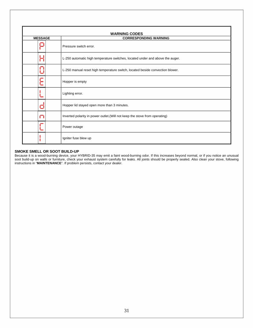
WARNING CODES MESSAGE CORRESPONDING WARNING
Pressure switch error.
L-250 automatic high temperature switches, located under and above the auger.
L-250 manual reset high temperature switch, located beside convection blower.
Hopper is empty
Lighting error.
Hopper lid stayed open more than 3 minutes.
Inverted polarity in power outlet.(Will not keep the stove from operating)
Power outage
Igniter fuse blew up
SMOKE SMELL OR SOOT BUILD-UP Because it is a wood-burning device, your HYBRID-35 may emit a faint wood-burning odor. If this increases beyond normal, or if you notice an unusual soot build-up on walls or furniture, check your exhaust system carefully for leaks. All joints should be properly sealed. Also clean your stove, following instructions in “MAINTENANCE”. If problem persists, contact your dealer.
32
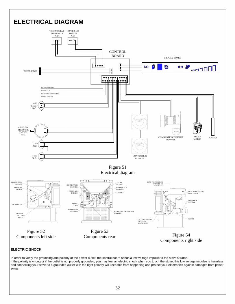
ELECTRICAL DIAGRAM
F-160N.O.
CONTROL BOARD
L-250N.C.
L-250RESET
N.C.
FRAME GROUND
L1(LINE NO CONNECTED)
L2(LINE COMMON)
L1(LINE HOT)
THERMOSTATTERMINALS
N.O.
HOPPER LIDSWITCH
N.O.
CONVECTIONBLOWER
COMBUSTION/EXHAUSTBLOWER
AUGERMOTOR
IGNITER
AIR FLOWPRESSURE
SWITCHN.O.
THERMISTOR
DISPLAY BOARD
Figure 51
Electrical diagram
CONVECTIONBLOWER
PRESSURESWITCH
THERMISTOR
CLEANINGACCESS
PANEL
Figure 52 Components left side
THERMOSTATTERMINAL
POWERCORD
FRESH AIRINTAKE
CONVECTIONBLOWER
EXHAUST/COMBUSTIONBLOWER
CONVECTIONBLOWER
EXHAUST
AUGERMOTOR
Figure 53
Components rear
GH TEMPERATUREWITCH L-250ANUAL RESET
HIGH TEMPERATURESWITCH L-250
AUTOMATIC
HIGH TEMPERATURESWITCH F-160
AIR SUPPLYCONTROL
IGNITER
Figure 54 Components right side
ELECTRIC SHOCK
In order to verify the grounding and polarity of the power outlet, the control board sends a low voltage impulse to the stove’s frame. If the polarity is wrong or if the outlet is not properly grounded, you may feel an electric shock when you touch the stove; this low voltage impulse is harmless and connecting your stove to a grounded outlet with the right polarity will keep this from happening and protect your electronics against damages from power surge.
33
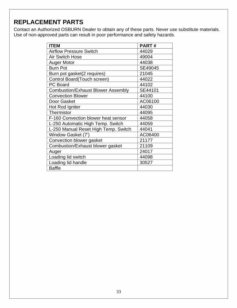
REPLACEMENT PARTS Contact an Authorized OSBURN Dealer to obtain any of these parts. Never use substitute materials. Use of non-approved parts can result in poor performance and safety hazards.
ITEM PART # Airflow Pressure Switch 44029 Air Switch Hose 49004 Auger Motor 44038 Burn Pot SE49045 Burn pot gasket(2 requires) 21045 Control Board(Touch screen) 44022 PC Board 44102 Combustion/Exhaust Blower Assembly SE44101 Convection Blower 44100 Door Gasket AC06100 Hot Rod Igniter 44030 Thermistor 44095 F-160 Convection blower heat sensor 44058 L-250 Automatic High Temp. Switch 44059 L-250 Manual Reset High Temp. Switch 44041 Window Gasket (7’) AC06400 Convection blower gasket 21177 Combustion/Exhaust blower gasket 21109 Auger 24017 Loading lid switch 44098 Loading lid handle 30527 Baffle
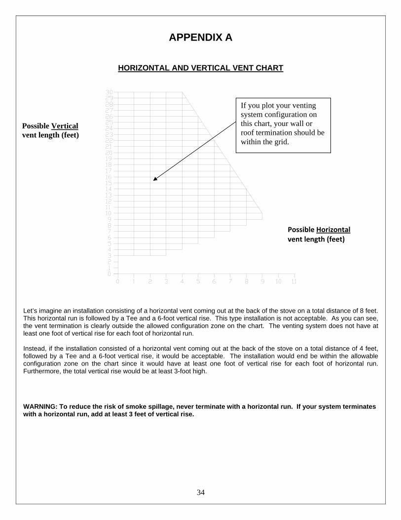
34
APPENDIX A
HORIZONTAL AND VERTICAL VENT CHART
Let’s imagine an installation consisting of a horizontal vent coming out at the back of the stove on a total distance of 8 feet. This horizontal run is followed by a Tee and a 6-foot vertical rise. This type installation is not acceptable. As you can see, the vent termination is clearly outside the allowed configuration zone on the chart. The venting system does not have at least one foot of vertical rise for each foot of horizontal run. Instead, if the installation consisted of a horizontal vent coming out at the back of the stove on a total distance of 4 feet, followed by a Tee and a 6-foot vertical rise, it would be acceptable. The installation would end be within the allowable configuration zone on the chart since it would have at least one foot of vertical rise for each foot of horizontal run. Furthermore, the total vertical rise would be at least 3-foot high.
WARNING: To reduce the risk of smoke spillage, never terminate with a horizontal run. If your system terminates with a horizontal run, add at least 3 feet of vertical rise.
Possible Vertical vent length (feet)
Possible Horizontal vent length (feet)
If you plot your venting system configuration on this chart, your wall or roof termination should be within the grid.
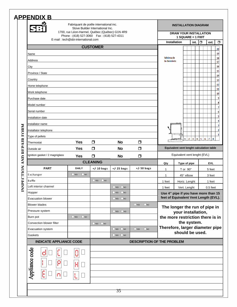
35
APPENDIX B
int. ext.
Name
Address
City
Province / State
Country
Home telephone
Work telephone
Purchase date
Model number
Serial number
Installation date
Installator name
Installator telephone
Type of pellets
Thermostat Yes NoOutside air Yes NoIgnition gasket / 2 magniglass Yes No
Fabriquant de poêle international inc.Stove Builder International Inc.
1700, rue Léon-Harmel, Québec (Québec) G1N 4R9Phone : (418) 527-3060 Fax : (418) 527-4311
E-mail : [email protected] Web site : www.drolet.ca
INSTALLATION DIAGRAM
InstallationCUSTOMER
Equivalent vent lenght (EVL)
Equivalent vent lenght calculation table
DRAW YOUR INSTALLATION1 SQUARE = 1 F00T
PART DAILY +/‐ 10 bag s +/‐ 25 bag s
E xchanger
Baffle
Left interior channel
Hopper
Evacuation blower
Blower blades
Pressure system
Burn pot
Convection blower filter
Evacuation system
Gaskets
CLEANING
Use 4” pipe if you have more than 15 feet of Equivalent Vent Length (EVL).
The longer the run of pipe in your installation,
the more restriction there is in the system.
Therefore, larger diameter pipe should be used.
45° elbow
Horiz. Lenght
Qty Type of pipe
T or 90°
1
1 feet
EVL
5 feet
1 feet
3 feet
1 feet
0.5 feetVert. Lenght
1+/‐ 50 bag s
YES NO
YES NO
YES NO
YES NO
YES NO
YES NO
YES NO
YES NO
YES NO
YES NO YES NO
YES NO
DESCRIPTION OF THE PROBLEMINDICATE APPLIANCE CODE
INSP
EC
TIO
NA
ND
RE
PAIR
FOR
M
36
OSBURN LIMITED LIFETIME WARRANTY The warranty of the manufacturer extends only to the original consumer purchaser and is not transferable. This warranty covers brand new products only, which have not been altered, modified nor repaired since shipment from factory. Proof of purchase (dated bill of sale), model name and serial number must be supplied when making any warranty claim to your OSBURN dealer. This warranty applies to normal residential use only. Damages caused by misuse, abuse, improper installation, lack of maintenance, negligence or accident during transportation are not covered by this warranty. This warranty does not cover any scratch, corrosion, warping or discoloration caused by over firing, abrasives or chemical cleaners. Any defect or damage caused by the use of unauthorized parts or others than original parts void this warranty. An authorized qualified technician must perform the installation in accordance with the instructions supplied with this product and all local and national building codes. Any service call related to an improper installation is not covered by this warranty. The manufacturer may require that defective products be returned or that digital pictures be provided to support the claim. Returned products are to be shipped prepaid to the manufacturer for investigation. If a product is found to be defective, the manufacturer will repair or replace such defect and reasonable transportation fees will be refunded. Repair work covered by the warranty, executed at the purchaser’s domicile by an authorized qualified technician requires the prior approval of the manufacturer. Labour cost and repair work to the account of the manufacturer are based on predetermined rate schedule and must not exceed the wholesale price of the replacement part. All labour and freight costs covered by this warranty are limited according to the table below. The manufacturer at its discretion may decide to repair or replace any part or unit after inspection and investigation of the defect. The manufacturer may, at its discretion, fully discharge all obligations with respect to this warranty by refunding the wholesale price of any warranted but defective parts The manufacturer shall in no event be responsible for any special, indirect, consequential damages of any nature, which are in excess of the original purchase price of the product.
DESCRIPTION WARRANTY APPLICATION
PARTS LABOUR Combustion chamber and heat exchanger (welds only), auger, and castings. Lifetime 5 years
Plating (defective manufacture) – subject to limitations above Lifetime n/a Convection blower, combustion blower, auger motor, and PC board 2 years 1 year Stainless steel baffle and parts 5 years 3 years Carbon steel baffle and parts 2 years 1 year Ceramic glass (thermal breakage only*) 2 years n/a Heat sensors, switches, and igniter. 1 year 1 year Paint (peeling), ceramic logs, gaskets, and masonry-like panels 1 year n/a
*Pictures required Shall your unit or a components be defective, contact immediately your OSBURN dealer. Prior to your call make sure you have the following information necessary to your warranty claim treatment:
• Your name, address and telephone number; • Bill of sale and dealer’s name;
• Serial number and model name as indicated on the nameplate fixed to the back of your unit;
• Nature of the defect and any relevant information. Before shipping your unit or defective component to our plant, you must obtain from your OSBURN dealer an Authorization Number. Any merchandise shipped to our plant without authorization will be refused automatically and returned to sender.