Embed Size (px)
Citation preview
2875 0697ASB
“SSJ” Series
Installation/Operation/PartsFor further operating, installation,
or maintenance assistance:
Call 1-888-782-7483
OWNER’S MANUAL
Vertical Jet Pumps
© 2013 Pentair Ltd. All Rights Reserved. S724 (Rev. 04/24/15)
293 WRIGHT STREET, DELAVAN, WI 53115 WWW.STA-RITE.COMPH: 888-782-7483
Safety 2
READ AND FOLLOW SAFETY INSTRUCTIONS!
This is the safety alert symbol. When you see this symbol on your pump or in this manual, look for one of the following signal words and be alert to the potential for personal injury:
warns about hazards that will cause serious personal injury, death or major property damage if ignored.
warns about hazards that can cause serious personal injury, death or major property damage if ignored.
warns about hazards that will or can cause minor personal injury or property damage if ignored.
The label NOTICE indicates special instructions which are important but not related to hazards.
Carefully read and follow all safety instructions in this manual and on pump.
Keep safety labels in good condition.
Replace missing or damaged safety labels.
Make workshops childproof; use padlocks and master switches; remove keys.
California Proposition 65 Warning
This product and related accessories contain chemicals known to the State of California to cause cancer, birth defects or other reproductive harm.
ELECTRICAL SAFETY
Capacitor voltage may be hazardous. To discharge motor capacitor, hold insulated handle screwdriver BY THE HANDLE and short capacitor terminals together. Do not touch metal screwdriver blade or capacitor terminals. If in doubt, consult a qualified electrician.
GENERAL SAFETY Do not touch an operating motor. Modern
motors can operate at high temperatures. To avoid burns when servicing pump, allow it to cool for 20 minutes after shut-down before handling.
Do not allow pump or any system component to freeze. To do so will void warranty.
Pump only water with this pump.
Periodically inspect pump and system components.
Wear safety glasses at all times when working on pumps.
Keep work area clean, uncluttered and properly lighted; store all unused tools and equipment.
Keep visitors at a safe distance from the work areas.
Pump body may explode if used as a booster pump unless relief valve capable of passing full pump flow at 75 psi is installed.
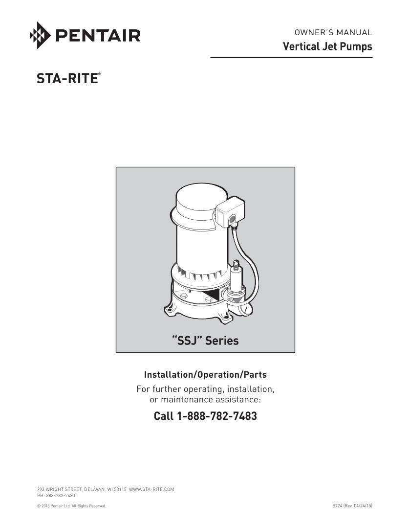
WARNINGHazardous pressure! Install pressure relief valve in discharge pipe.Release all pressure on system before working on any component.
WARNING
Hazardous voltage. Can shock, burn, or cause death.Ground pump before connecting to power supply. Disconnect power before working on pump, motor or tank.
Wire motor for correct voltage. See “Electri cal” section of this manual and motor nameplate.
Ground motor before connecting to power supply.
Meet National Electrical Code, Canadian Elec tri cal Code, and local codes for all wiring.
Follow wiring instructions in this manual when connecting motor to power lines.
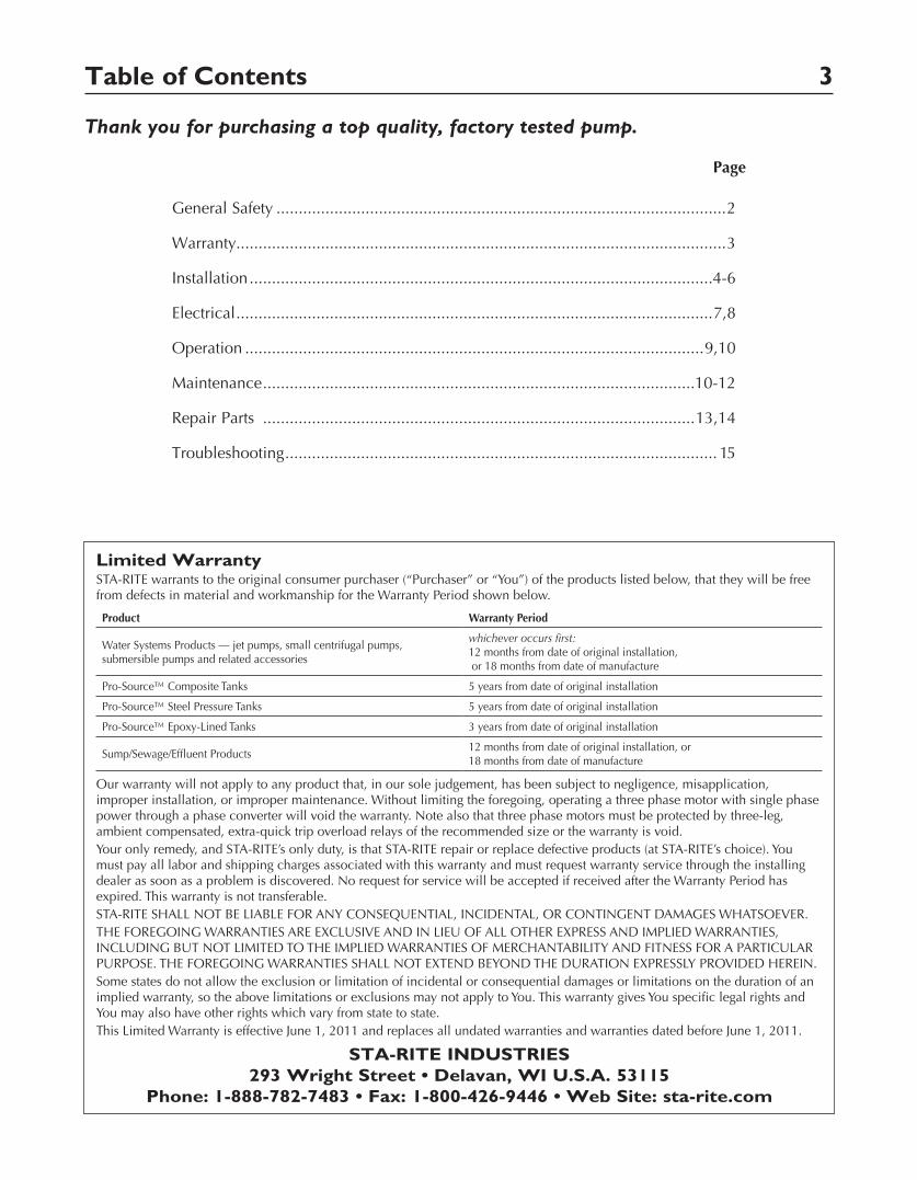
Table of Contents 3
Thank you for purchasing a top quality, factory tested pump.
Page
General Safety .....................................................................................................2
Warranty..............................................................................................................3
Installation ........................................................................................................4-6
Electrical ...........................................................................................................7,8
Operation .......................................................................................................9,10
Maintenance .................................................................................................10-12
Repair Parts .................................................................................................13,14
Troubleshooting ................................................................................................. 15
Limited WarrantySTA-RITE warrants to the original consumer purchaser (“Purchaser” or “You”) of the products listed below, that they will be free from defects in material and workmanship for the Warranty Period shown below.
Product Warranty Period
Water Systems Products — jet pumps, small centrifugal pumps, submersible pumps and related accessories
whichever occurs first: 12 months from date of original installation, or 18 months from date of manufacture
Pro-Source™ Composite Tanks 5 years from date of original installation
Pro-Source™ Steel Pressure Tanks 5 years from date of original installation
Pro-Source™ Epoxy-Lined Tanks 3 years from date of original installation
Sump/Sewage/Effluent Products12 months from date of original installation, or 18 months from date of manufacture
Our warranty will not apply to any product that, in our sole judgement, has been subject to negligence, misapplication, improper installation, or improper maintenance. Without limiting the foregoing, operating a three phase motor with single phase power through a phase converter will void the warranty. Note also that three phase motors must be protected by three-leg, ambient compensated, extra-quick trip overload relays of the recommended size or the warranty is void.Your only remedy, and STA-RITE’s only duty, is that STA-RITE repair or replace defective products (at STA-RITE’s choice). You must pay all labor and shipping charges associated with this warranty and must request warranty service through the installing dealer as soon as a problem is discovered. No request for service will be accepted if received after the Warranty Period has expired. This warranty is not transferable.STA-RITE SHALL NOT BE LIABLE FOR ANY CONSEQUENTIAL, INCIDENTAL, OR CONTINGENT DAMAGES WHATSOEVER.THE FOREGOING WARRANTIES ARE EXCLUSIVE AND IN LIEU OF ALL OTHER EXPRESS AND IMPLIED WARRANTIES, INCLUDING BUT NOT LIMITED TO THE IMPLIED WARRANTIES OF MERCHANTABILITY AND FITNESS FOR A PARTICULAR PURPOSE. THE FOREGOING WARRANTIES SHALL NOT EXTEND BEYOND THE DURATION EXPRESSLY PROVIDED HEREIN.Some states do not allow the exclusion or limitation of incidental or consequential damages or limitations on the duration of an implied warranty, so the above limitations or exclusions may not apply to You. This warranty gives You specific legal rights and You may also have other rights which vary from state to state.This Limited Warranty is effective June 1, 2011 and replaces all undated warranties and warranties dated before June 1, 2011.
STA-RITE INDUSTRIES 293 Wright Street • Delavan, WI U.S.A. 53115
Phone: 1-888-782-7483 • Fax: 1-800-426-9446 • Web Site: sta-rite.com
Installation 4
BEFORE YOU INSTALL YOUR PUMPNOTICE: For proper performance, pump MUST be matched to ejector and to well depth. This pump is designed for wells from 25 ft. to 130 ft. depth from well head to water.
• Long runs and many fittings increase friction and reduce flow. Locate pump as close to well as possible: use as few elbows and fittings as possible.
• Be sure well is clear of sand. Sand will plug the pump and void the warranty.
• Protect pump and all piping from freezing. Freezing will split pipe, damage pump and void the warranty. Check locally for frost protection requirements (usually pipe must be 12” below frost line and pump must be insulated).
• Be sure all pipes and foot valve are clean and in good condition.
• Remove air pockets in suction pipe.
• Make sure there are no leaks in the suction pipe. Use PTFE pipe thread sealant tape tape to seal pipe joints.
• Unions installed near pump and well will aid in servicing. Leave room to use wrenches.
• Plug 1” drive port when installing on shallow well.
IMPORTANT: Your well must be able to replenish the water level faster than the flow out through pump!
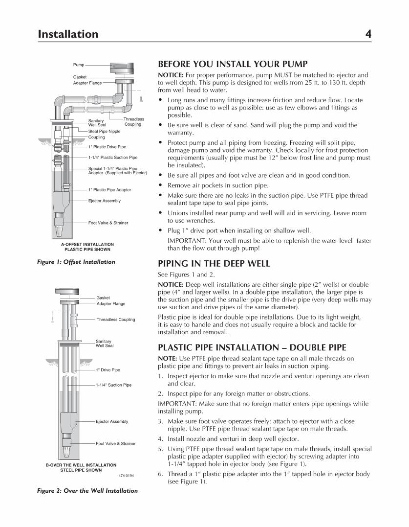
PIPING IN THE DEEP WELLSee Figures 1 and 2.
NOTICE: Deep well installations are either single pipe (2” wells) or double pipe (4” and larger wells). In a double pipe installation, the larger pipe is the suction pipe and the smaller pipe is the drive pipe (very deep wells may use suction and drive pipes of the same diameter).
Plastic pipe is ideal for double pipe installations. Due to its light weight, it is easy to handle and does not usually require a block and tackle for installation and removal.
PLASTIC PIPE INSTALLATION – DOUBLE PIPENOTE: Use PTFE pipe thread sealant tape tape on all male threads on plastic pipe and fittings to prevent air leaks in suction piping.
1. Inspect ejector to make sure that nozzle and venturi openings are clean and clear.
2. Inspect pipe for any foreign matter or obstructions.
IMPORTANT: Make sure that no foreign matter enters pipe openings while installing pump.
3. Make sure foot valve operates freely: attach to ejector with a close nipple. Use PTFE pipe thread sealant tape tape on male threads.
4. Install nozzle and venturi in deep well ejector.
5. Using PTFE pipe thread sealant tape tape on male threads, install special plastic pipe adapter (supplied with ejector) by screwing adapter into 1-1/4” tapped hole in ejector body (see Figure 1).
6. Thread a 1” plastic pipe adapter into the 1” tapped hole in ejector body (see Figure 1).
Pump Pump
Gasket GasketAdapter Flange Adapter Flange
Threadless Coupling
SanitaryWell Seal
Steel Pipe NippleCoupling
1" Plastic Drive Pipe
1" Plastic Pipe Adapter
Ejector Assembly
Foot Valve & Strainer
1-1/4" Plastic Suction Pipe
Special 1-1/4" Plastic PipeAdapter. (Supplied with Ejector)
SanitaryWell Seal
1" Drive Pipe
Ejector Assembly
Foot Valve & Strainer
1-1/4" Suction Pipe
Threadless Coupling
A-OFFSET INSTALLATIONPLASTIC PIPE SHOWN
B-OVER THE WELL INSTALLATIONSTEEL PIPE SHOWN
474 0194
Figure 1: Offset Installation
Pump Pump
Gasket GasketAdapter Flange Adapter Flange
Threadless Coupling
SanitaryWell Seal
Steel Pipe NippleCoupling
1" Plastic Drive Pipe
1" Plastic Pipe Adapter
Ejector Assembly
Foot Valve & Strainer
1-1/4" Plastic Suction Pipe
Special 1-1/4" Plastic PipeAdapter. (Supplied with Ejector)
SanitaryWell Seal
1" Drive Pipe
Ejector Assembly
Foot Valve & Strainer
1-1/4" Suction Pipe
Threadless Coupling
A-OFFSET INSTALLATIONPLASTIC PIPE SHOWN
B-OVER THE WELL INSTALLATIONSTEEL PIPE SHOWN
474 0194
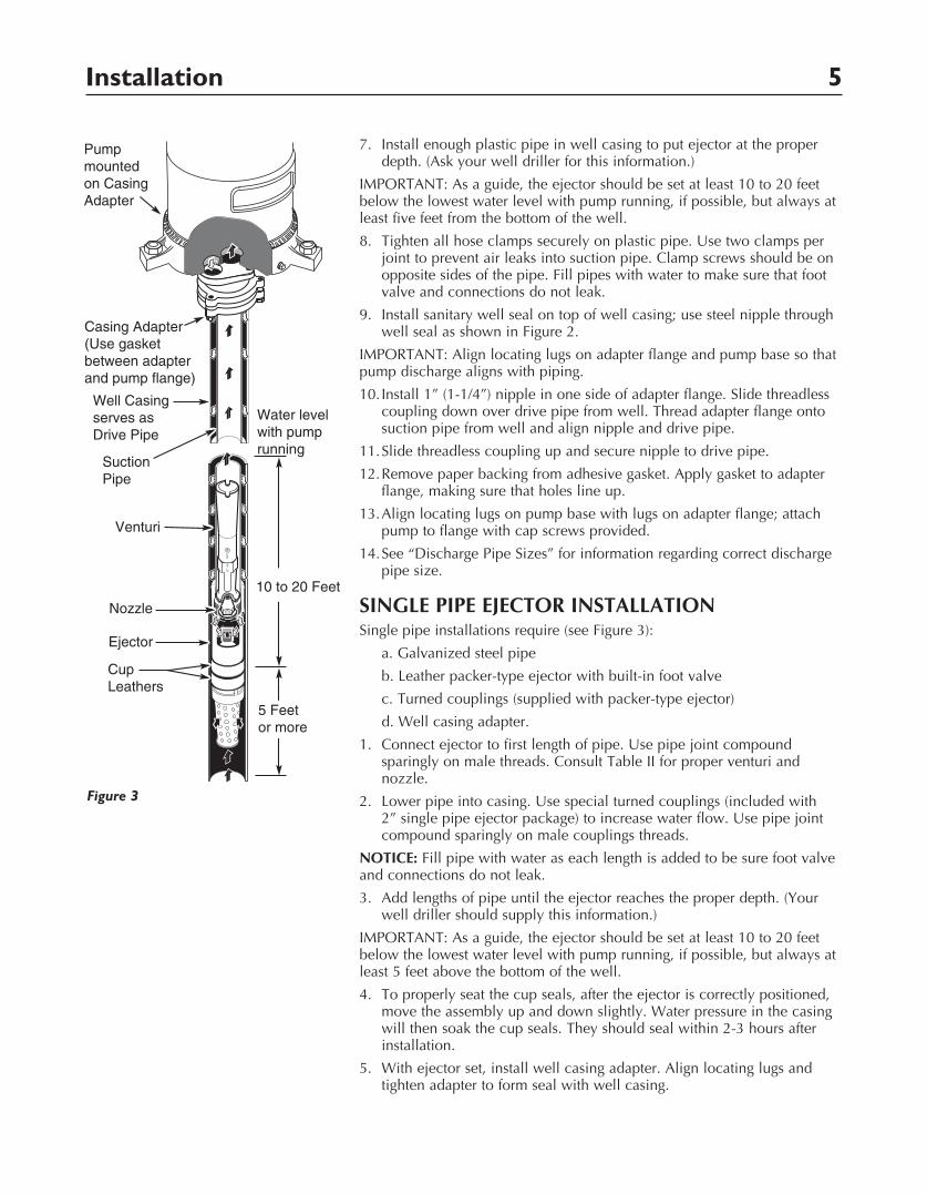
Figure 2: Over the Well Installation
Installation 5
7. Install enough plastic pipe in well casing to put ejector at the proper depth. (Ask your well driller for this information.)
IMPORTANT: As a guide, the ejector should be set at least 10 to 20 feet below the lowest water level with pump running, if possible, but always at least five feet from the bottom of the well.
8. Tighten all hose clamps securely on plastic pipe. Use two clamps per joint to prevent air leaks into suction pipe. Clamp screws should be on opposite sides of the pipe. Fill pipes with water to make sure that foot valve and connections do not leak.
9. Install sanitary well seal on top of well casing; use steel nipple through well seal as shown in Figure 2.
IMPORTANT: Align locating lugs on adapter flange and pump base so that pump discharge aligns with piping.
10. Install 1” (1-1/4”) nipple in one side of adapter flange. Slide threadless coupling down over drive pipe from well. Thread adapter flange onto suction pipe from well and align nipple and drive pipe.
11. Slide threadless coupling up and secure nipple to drive pipe.
12. Remove paper backing from adhesive gasket. Apply gasket to adapter flange, making sure that holes line up.
13. Align locating lugs on pump base with lugs on adapter flange; attach pump to flange with cap screws provided.
14. See “Discharge Pipe Sizes” for information regarding correct discharge pipe size.
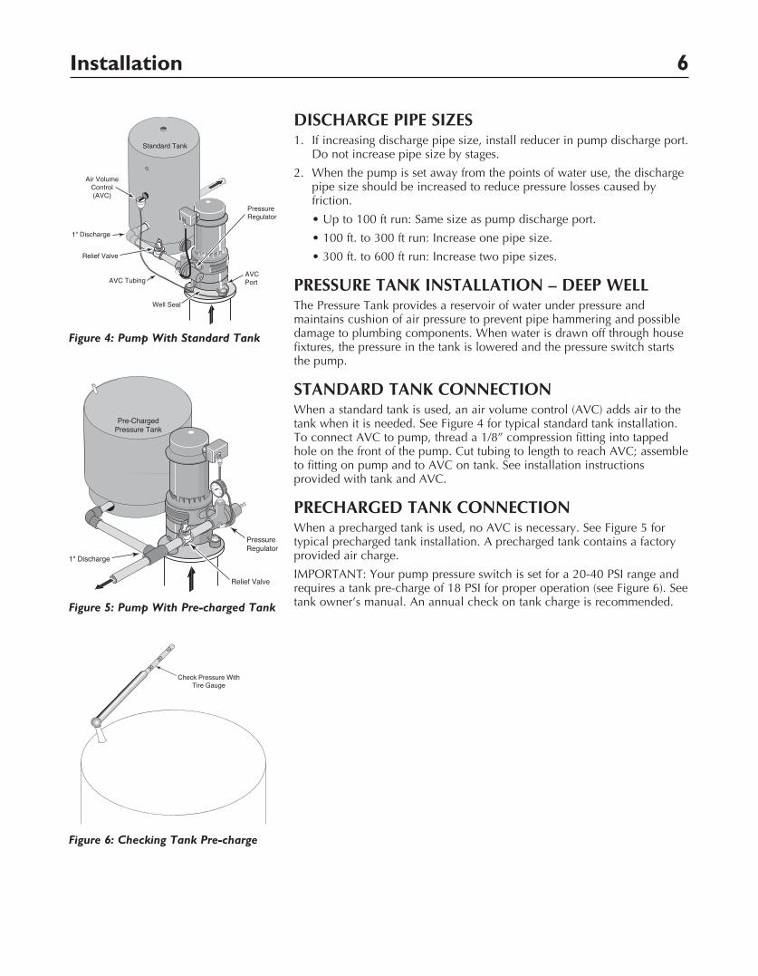
SINGLE PIPE EJECTOR INSTALLATIONSingle pipe installations require (see Figure 3):
a. Galvanized steel pipe
b. Leather packer-type ejector with built-in foot valve
c. Turned couplings (supplied with packer-type ejector)
d. Well casing adapter.
1. Connect ejector to first length of pipe. Use pipe joint compound sparingly on male threads. Consult Table II for proper venturi and nozzle.
2. Lower pipe into casing. Use special turned couplings (included with 2” single pipe ejector package) to increase water flow. Use pipe joint compound sparingly on male couplings threads.
NOTICE: Fill pipe with water as each length is added to be sure foot valve and connections do not leak.
3. Add lengths of pipe until the ejector reaches the proper depth. (Your well driller should supply this information.)
IMPORTANT: As a guide, the ejector should be set at least 10 to 20 feet below the lowest water level with pump running, if possible, but always at least 5 feet above the bottom of the well.
4. To properly seat the cup seals, after the ejector is correctly positioned, move the assembly up and down slightly. Water pressure in the casing will then soak the cup seals. They should seal within 2-3 hours after installation.
5. With ejector set, install well casing adapter. Align locating lugs and tighten adapter to form seal with well casing.
Well Casingserves asDrive Pipe
Suction Pipe
Venturi
Nozzle
Ejector
Casing Adapter(Use gasketbetween adapter and pump flange)
CupLeathers
Pump mountedon Casing Adapter
5 Feet or more
10 to 20 Feet
Water level with pumprunning
2357d 0797Figure 3
Installation 6
DISCHARGE PIPE SIZES1. If increasing discharge pipe size, install reducer in pump discharge port.
Do not increase pipe size by stages.
2. When the pump is set away from the points of water use, the discharge pipe size should be increased to reduce pressure losses caused by friction.
•Upto100ftrun:Samesizeaspumpdischargeport.
•100ft.to300ftrun:Increaseonepipesize.
•300ft.to600ftrun:Increasetwopipesizes.
PRESSURE TANK INSTALLATION – DEEP WELL The Pressure Tank provides a reservoir of water under pressure and maintains cushion of air pressure to prevent pipe hammering and possible damage to plumbing components. When water is drawn off through house fixtures, the pressure in the tank is lowered and the pressure switch starts the pump.
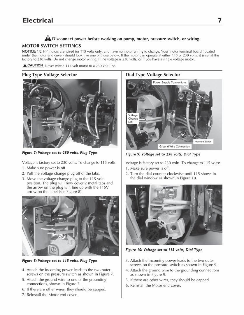
STANDARD TANK CONNECTIONWhen a standard tank is used, an air volume control (AVC) adds air to the tank when it is needed. See Figure 4 for typical standard tank installation. To connect AVC to pump, thread a 1/8” compression fitting into tapped hole on the front of the pump. Cut tubing to length to reach AVC; assemble to fitting on pump and to AVC on tank. See installation instructions provided with tank and AVC.
PRECHARGED TANK CONNECTIONWhen a precharged tank is used, no AVC is necessary. See Figure 5 for typical precharged tank installation. A precharged tank contains a factory provided air charge.
IMPORTANT: Your pump pressure switch is set for a 20-40 PSI range and requires a tank pre-charge of 18 PSI for proper operation (see Figure 6). See tank owner’s manual. An annual check on tank charge is recommended.
Air VolumeControl(AVC)
Standard Tank
AVC Port
2355b 0697
1" Discharge
Relief Valve
Pressure Regulator
Well Seal
AVC Tubing
Figure 4: Pump With Standard Tank
1054 0415
10
20
30
Check Pressure WithTire Gauge
Figure 6: Checking Tank Pre-charge
20
100
80
6040
Relief Valve
Pressure Regulator
1" Discharge
Pre-ChargedPressure Tank
2358b 0415Figure 5: Pump With Pre-charged Tank
Electrical 7
Plug Type Voltage Selector
Voltage is factory set to 230 volts. To change to 115 volts:1. Make sure power is off.2. Pull the voltage change plug off of the tabs.3. Move the voltage change plug to the 115 volt
position. The plug will now cover 2 metal tabs and the arrow on the plug will line up with the 115V arrow on the label (see Figure 8).
4. Attach the incoming power leads to the two outer screws on the pressure switch as shown in Figure 7.
5. Attach the ground wire to one of the grounding connections, shown in Figure 7.
6. If there are other wires, they should be capped.7. Reinstall the Motor end cover.
Dial Type Voltage Selector
Voltage is factory set to 230 volts. To change to 115 volts:1. Make sure power is off.2. Turn the dial counter-clockwise until 115 shows in
the dial window as shown in Figure 10.
3. Attach the incoming power leads to the two outer screws on the pressure switch as shown in Figure 9.
4. Attach the ground wire to the grounding connections as shown in Figure 9.
5. If there are other wires, they should be capped.6. Reinstall the Motor end cover.
Disconnect power before working on pump, motor, pressure switch, or wiring.
NOTICE: 1/2 HP motors are wired for 115 volts only, and have no motor wiring to change. Your motor terminal board (located under the motor end cover) should look like one of those below. If the motor can operate at either 115 or 230 volts, it is set at the factory to 230 volts. Do not change motor wiring if line voltage is 230 volts, or if you have a single voltage motor.
Never wire a 115 volt motor to a 230 volt line.
MOTOR SWITCH SETTINGS
Figure 7: Voltage set to 230 volts, Plug Type
Figure 8: Voltage set to 115 volts, Plug Type
Figure 9: Voltage set to 230 volts, Dial Type
Ground Wire Connection
Power Supply Connections
VoltageChangeDial
Pressure Switch
Figure 10: Voltage set to 115 volts, Dial Type
Electrical 8
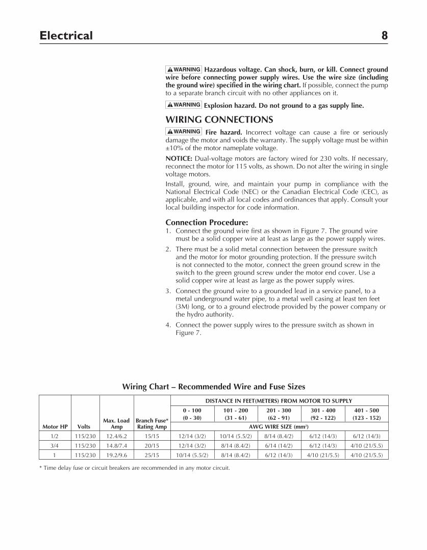
Hazardous voltage. Can shock, burn, or kill. Connect ground wire before connecting power supply wires. Use the wire size (including the ground wire) specified in the wiring chart. If possible, connect the pump to a separate branch circuit with no other appliances on it.
Explosion hazard. Do not ground to a gas supply line.
WIRING CONNECTIONS Fire hazard. Incorrect voltage can cause a fire or seriously
damage the motor and voids the warranty. The supply voltage must be within ±10% of the motor nameplate voltage.
NOTICE: Dual-voltage motors are factory wired for 230 volts. If necessary, reconnect the motor for 115 volts, as shown. Do not alter the wiring in single voltage motors.Install, ground, wire, and maintain your pump in compliance with the National Electrical Code (NEC) or the Canadian Electrical Code (CEC), as applicable, and with all local codes and ordinances that apply. Consult your local building inspector for code information.
Connection Procedure:1. Connect the ground wire first as shown in Figure 7. The ground wire
must be a solid copper wire at least as large as the power supply wires.
2. There must be a solid metal connection between the pressure switch and the motor for motor grounding protection. If the pressure switch is not connected to the motor, connect the green ground screw in the switch to the green ground screw under the motor end cover. Use a solid copper wire at least as large as the power supply wires.
3. Connect the ground wire to a grounded lead in a service panel, to a metal underground water pipe, to a metal well casing at least ten feet (3M) long, or to a ground electrode provided by the power company or the hydro authority.
4. Connect the power supply wires to the pressure switch as shown in Figure 7.
Wiring Chart – Recommended Wire and Fuse Sizes
DISTANCE IN FEET(METERS) FROM MOTOR TO SUPPLY
0 - 100 101 - 200 201 - 300 301 - 400 401 - 500 Max. Load Branch Fuse* (0 - 30) (31 - 61) (62 - 91) (92 - 122) (123 - 152)
Motor HP Volts Amp Rating Amp AWG WIRE SIZE (mm2)
1/2 115/230 12.4/6.2 15/15 12/14 (3/2) 10/14 (5.5/2) 8/14 (8.4/2) 6/12 (14/3) 6/12 (14/3)
3/4 115/230 14.8/7.4 20/15 12/14 (3/2) 8/14 (8.4/2) 6/14 (14/2) 6/12 (14/3) 4/10 (21/5.5)
1 115/230 19.2/9.6 25/15 10/14 (5.5/2) 8/14 (8.4/2) 6/12 (14/3) 4/10 (21/5.5) 4/10 (21/5.5)
* Time delay fuse or circuit breakers are recommended in any motor circuit.
Operation 9
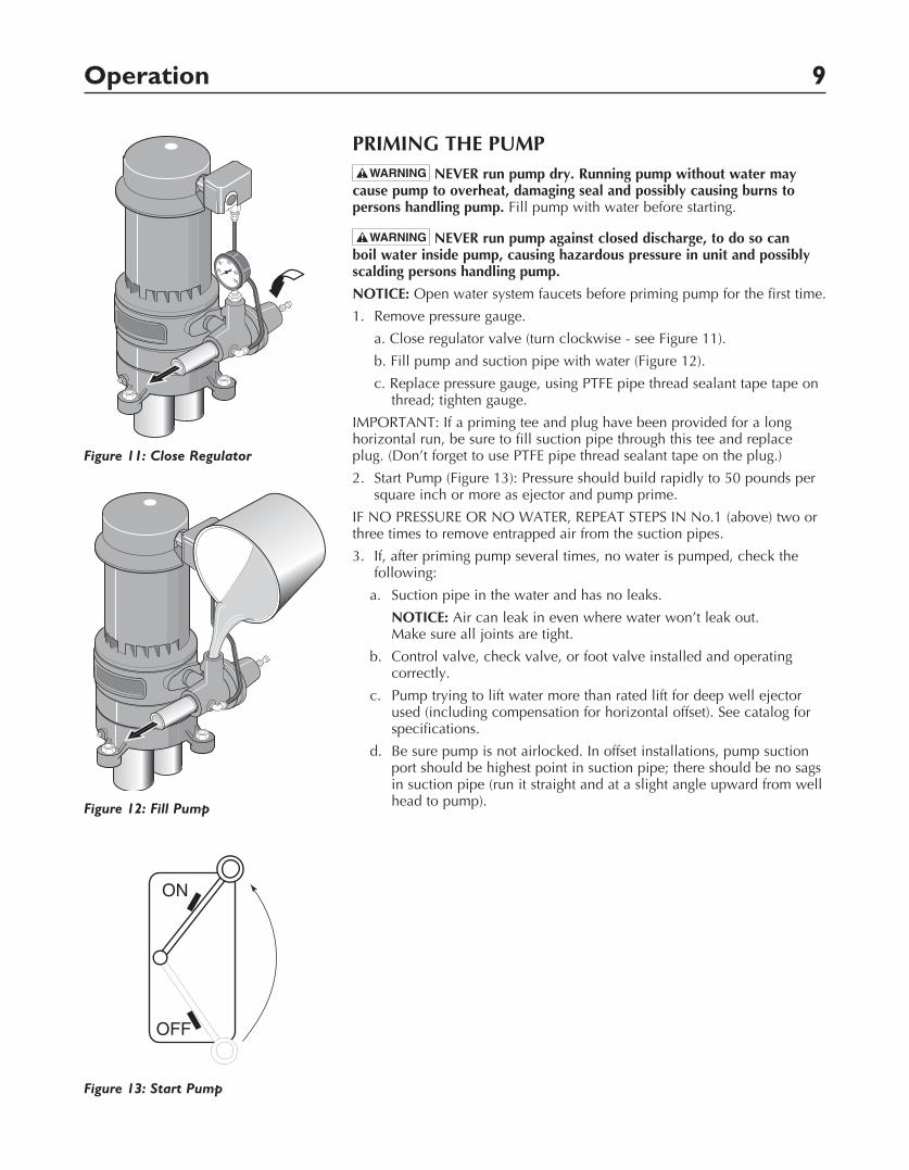
PRIMING THE PUMP
NEVER run pump dry. Running pump without water may cause pump to overheat, damaging seal and possibly causing burns to persons handling pump. Fill pump with water before starting.
NEVER run pump against closed dis charge, to do so can boil water inside pump, causing hazardous pressure in unit and possibly scalding persons handling pump.
NOTICE: Open water system faucets before priming pump for the first time.
1. Remove pressure gauge.
a. Close regulator valve (turn clockwise - see Figure 11).
b. Fill pump and suction pipe with water (Figure 12).
c. Replace pressure gauge, using PTFE pipe thread sealant tape tape on thread; tighten gauge.
IMPORTANT: If a priming tee and plug have been provided for a long horizontal run, be sure to fill suction pipe through this tee and replace plug. (Don’t forget to use PTFE pipe thread sealant tape on the plug.)
2. Start Pump (Figure 13): Pressure should build rapidly to 50 pounds per square inch or more as ejector and pump prime.
IF NO PRESSURE OR NO WATER, REPEAT STEPS IN No.1 (above) two or three times to remove entrapped air from the suction pipes.
3. If, after priming pump several times, no water is pumped, check the following:
a. Suction pipe in the water and has no leaks.
NOTICE: Air can leak in even where water won’t leak out. Make sure all joints are tight.
b. Control valve, check valve, or foot valve installed and operating correctly.
c. Pump trying to lift water more than rated lift for deep well ejector used (including compensation for horizontal offset). See catalog for specifications.
d. Be sure pump is not airlocked. In offset installations, pump suction port should be highest point in suction pipe; there should be no sags in suction pipe (run it straight and at a slight angle upward from well head to pump).
20
100
80
6040
2361a 0697Figure 11: Close Regulator
2360a 0697Figure 12: Fill Pump
ON
OFF
1060 0697
Figure 13: Start Pump
Operation / Maintenance 10
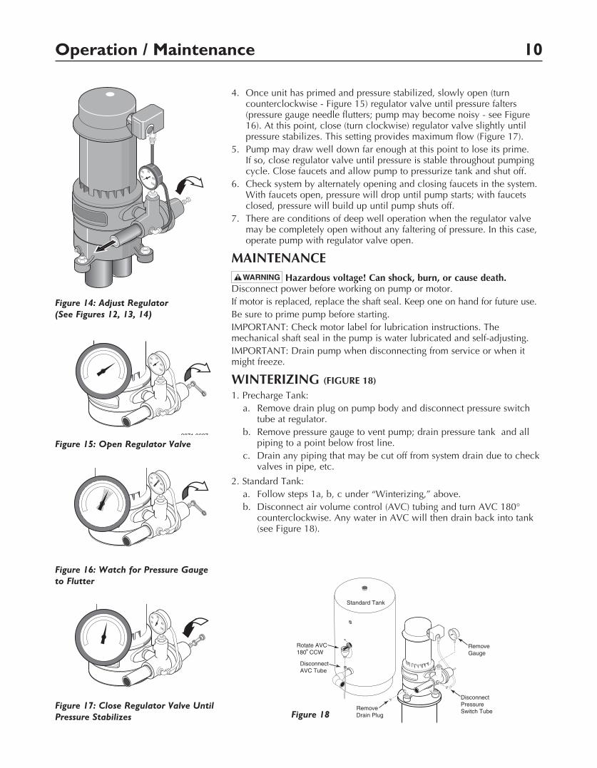
4. Once unit has primed and pressure stabilized, slowly open (turn counterclockwise - Figure 15) regulator valve until pressure falters (pressure gauge needle flutters; pump may become noisy - see Figure 16). At this point, close (turn clockwise) regulator valve slightly until pressure stabilizes. This setting provides maximum flow (Figure 17).
5. Pump may draw well down far enough at this point to lose its prime. If so, close regulator valve until pressure is stable throughout pumping cycle. Close faucets and allow pump to pressurize tank and shut off.
6. Check system by alternately opening and closing faucets in the system. With faucets open, pressure will drop until pump starts; with faucets closed, pressure will build up until pump shuts off.
7. There are conditions of deep well operation when the regulator valve may be completely open without any faltering of pressure. In this case, operate pump with regulator valve open.
MAINTENANCE
Hazardous voltage! Can shock, burn, or cause death. Disconnect power before working on pump or motor.If motor is replaced, replace the shaft seal. Keep one on hand for future use.Be sure to prime pump before starting.IMPORTANT: Check motor label for lubrication instructions. The mechanical shaft seal in the pump is water lubricated and self-adjusting.IMPORTANT: Drain pump when disconnecting from service or when it might freeze.
WINTERIZING (FIGURE 18)
1. Precharge Tank:a. Remove drain plug on pump body and disconnect pressure switch
tube at regulator.b. Remove pressure gauge to vent pump; drain pressure tank and all
piping to a point below frost line.c. Drain any piping that may be cut off from system drain due to check
valves in pipe, etc.
2. Standard Tank:a. Follow steps 1a, b, c under “Winterizing,” above.b. Disconnect air volume control (AVC) tubing and turn AVC 180°
counterclockwise. Any water in AVC will then drain back into tank (see Figure 18).
20
100
80
6040
1030a 0697
Figure 14: Adjust Regulator (See Figures 12, 13, 14)
20
100
80
6040
2871 0697
Figure 15: Open Regulator Valve
20
100
80
6040
2873 0697
Figure 17: Close Regulator Valve Until Pressure Stabilizes
20
100
80
6040
2872 0697
Figure 16: Watch for Pressure Gauge to Flutter
RemoveGauge
RemoveDrain Plug
20
100
80
6040
DisconnectPressureSwitch Tube
1065 0697
Standard Tank
DisconnectAVC Tube
Rotate AVC180 CCW
Figure 18
Maintenance 11
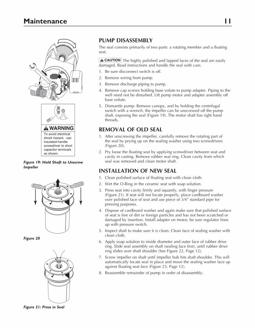
PUMP DISASSEMBLYThe seal consists primarily of two parts: a rotating member and a floating seat.
The highly polished and lapped faces of the seal are easily damaged. Read instructions and handle the seal with care.
1. Be sure disconnect switch is off.
2. Remove wiring from pump.
3. Remove discharge piping to pump.
4. Remove cap screws holding base volute to pump adapter. Piping to the well need not be disturbed. Lift pump motor and adapter assembly off base volute.
5. Dismantle pump: Remove canopy, and by holding the centrifugal switch with a wrench, the impeller can be unscrewed off the pump shaft, exposing the seal (Figure 19). The motor shaft has right hand threads.
REMOVAL OF OLD SEAL1. After unscrewing the impeller, carefully remove the rotating part of
the seal by prying up on the sealing washer using two screwdrivers (Figure 20).
2. Pry loose the floating seat by applying screwdriver between seat and cavity in casting. Remove rubber seat ring. Clean cavity from which seal was removed and clean motor shaft.
INSTALLATION OF NEW SEAL1. Clean polished surface of floating seat with clean cloth.
2. Wet the O-Ring in the ceramic seat with soap solution.
3. Press seat into cavity firmly and squarely, with finger pressure (Figure 21). If seat will not locate properly, place cardboard washer over polished face of seat and use piece of 3/4” standard pipe for pressing purposes.
4. Dispose of cardboard washer and again make sure that polished surface of seat is free of dirt or foreign particles and has not been scratched or damaged by insertion. Install adapter on motor; be sure regulator lines up with pressure switch.
5. Inspect shaft to make sure it is clean. Clean face of sealing washer with clean cloth.
6. Apply soap solution to inside diameter and outer face of rubber drive ring. Slide seal assembly on shaft (sealing face first), until rubber drive ring slides over shaft shoulder (See Figure 22, Page 12).
7. Screw impeller on shaft until impeller hub hits shaft shoulder. This will automatically locate seal in place and move the sealing washer face up against floating seat face (Figure 23, Page 12).
8. Reassemble remainder of pump in order of disassembly.
A
B
L2
L1
A
B
L2
L1
174 0697
Figure 19: Hold Shaft to Unscrew Impeller
1067b 0697Figure 20
To avoid electrical shock hazard, use insulated-handle screwdriver to short capacitor terminals as shown.
2874 0697Figure 21: Press in Seal
Maintenance 12
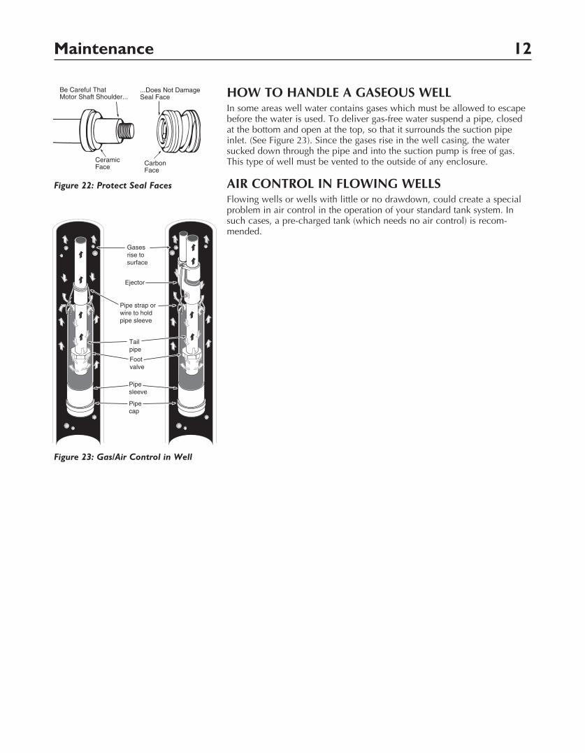
HOW TO HANDLE A GASEOUS WELLIn some areas well water contains gases which must be allowed to escape before the water is used. To deliver gas-free water suspend a pipe, closed at the bottom and open at the top, so that it surrounds the suction pipe inlet. (See Figure 23). Since the gases rise in the well casing, the water sucked down through the pipe and into the suction pump is free of gas. This type of well must be vented to the outside of any enclosure.
AIR CONTROL IN FLOWING WELLSFlowing wells or wells with little or no drawdown, could create a special problem in air control in the operation of your standard tank system. In such cases, a pre-charged tank (which needs no air control) is recom-mended.
Pipe strap orwire to holdpipe sleeve
Pipesleeve
Pipecap
Tailpipe
Footvalve
Ejector
2876 0697
Gasesrise to surface
Figure 23: Gas/Air Control in Well
1072 0697
CeramicFace Carbon
Face
Be Careful ThatMotor Shaft Shoulder...
...Does Not DamageSeal Face
Figure 22: Protect Seal Faces
1
2
3
4
5
7
6 8 9
10
11
12
13
14
2365 0396
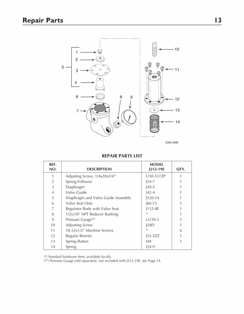
REPAIR PARTS LIST
Repair Parts 13
(*) Standard hardware item, available locally.(**) Pressure Gauge sold separately, not included with J212-19E, see Page 14.
REF. MODEL NO. DESCRIPTION J212-19E QTY.
1 Adjusting Screw, 1/4x20x3/4” U30-537ZP 1 2 Spring Follower J24-7 1 3 Diaphragm J20-5 1 4 Valve Guide J42-4 1 5 Diaphragm and Valve Guide Assembly J120-14 1 6 Valve Seat Only J66-15 1 7 Regulator Body with Valve Seat J112-8E 1 8 1/2x1/8” NPT Reducer Bushing * 1 9 Pressure Gauge** U239-3 1 10 Adjusting Screw J28D 1 11 10-32x1/2” Machine Screws * 6 12 Regular Bonnet J52-5ZZ 1 13 Spring Button J48 1 14 Spring J24-9
Repair Parts 14
1
2
3
4
5
9
10
11
1213
14
15
20
16
17
18
19
6
2875 0697
7
8
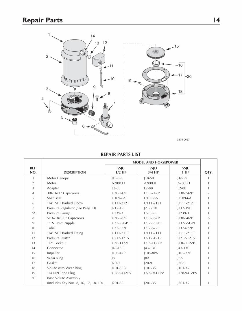
REPAIR PARTS LIST
MODEL AND HORSEPOWER
REF. SSJC SSJD SSJE NO. DESCRIPTION 1/2 HP 3/4 HP 1 HP QTY.
1 Motor Canopy J18-59 J18-59 J18-59 1 2 Motor A200CH A200DH A200EH 1 3 Adapter L2-8B L2-8B L2-8B 1 4 3/8-16x1” Capscrews U30-74ZP U30-74ZP U30-74ZP 2 5 Shaft seal U109-6A U109-6A U109-6A 1 6 1/4” NPT Barbed Elbow U111-212T U111-212T U111-212T 1 7 Pressure Regulator (See Page 13) J212-19E J212-19E J212-19E 1 7A Pressure Gauge U239-3 U239-3 U239-3 1 8 5/16-18x5/8” Capscrews U30-58ZP U30-58ZP U30-58ZP 6 9 1” NPTx2” Nipple U37-55GPT U37-55GPT U37-55GPT 1 10 Tube U37-672P U37-672P U37-672P 1 11 1/4” NPT Barbed Fitting U111-211T U111-211T U111-211T 1 12 Pressure Switch U217-1215 U217-1215 U217-1215 1 13 1/2” Locknut U36-112ZP U36-112ZP U36-112ZP 1 14 Connector J43-13C J43-13C J43-13C 1 15 Impeller J105-42P J105-8PN J105-22P 1 16 Wear Ring J8 J8A J8A 1 17 Gasket J20-9 J20-9 J20-9 1 18 Volute with Wear Ring J101-35B J101-35 J101-35 1 19 1/4 NPT Pipe Plug U78-941ZPV U78-941ZPV U78-941ZPV 1 20 Base Volute Assembly (Includes Key Nos. 8, 16, 17, 18, 19) J201-35 J201-35 J201-35 1
Troubleshooting 15
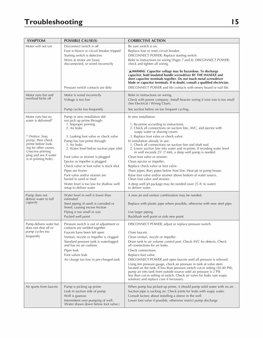
SYMPTOM POSSIBLE CAUSE(S) CORRECTIVE ACTION Motor will not run Disconnect switch is off Be sure switch is on. Fuse is blown or circuit breaker tripped Replace fuse or reset circuit breaker. Starting switch is defective DISCONNECT POWER; Replace starting switch. Wires at motor are loose, Refer to instructions on wiring (Pages 7 and 8). DISCONNECT POWER; disconnected, or wired incorrectly check and tighten all wiring. Capacitor voltage may be hazardous. To discharge capacitor, hold insulated handle screwdriver BY THE HANDLE and short capacitor terminals together. Do not touch metal screwdriver blade or capacitor terminals. If in doubt, consult a qualified electrician.
Pressure switch contacts are dirty DISCONNECT POWER and file contacts with emery board or nail file.
Motor runs hot and Motor is wired incorrectly Refer to instructions on wiring. overload kicks off Voltage is too low Check with power company. Install heavier wiring if wire size is too small (See Electrical / Wiring Chart).
Pump cycles too frequently See section below on too frequent cycling.
Motor runs but no Pump in new installation did In new installation: water is delivered* not pick up prime through: 1. Improper priming 1. Re-prime according to instructions. 2. Air leaks 2. Check all connections on suction line, AVC, and ejector with soapy water or shaving cream. 3. Leaking foot valve or check valve 3. Replace foot valve or check valve. Pump has lost prime through: In installation already in use: 1. Air leaks 1. Check all connections on suction line and shaft seal. 2. Water level below suction pipe inlet 2. Lower suction line into water and re-prime. If receding water level in well exceeds 25’ (7.6M), a deep well pump is needed. Foot valve or strainer is plugged Clean foot valve or strainer. Ejector or impeller is plugged Clean ejector or impeller. Check valve or foot valve is stuck shut Replace check valve or foot valve. Pipes are frozen Thaw pipes. Bury pipes below frost line. Heat pit or pump house. Foot valve and/or strainer are Raise foot valve and/or strainer above bottom of water source. buried in sand or mud Clean foot valve and strainer.
Water level is too low for shallow well A deep well jet package may be needed (over 25 ft. to water) setup to deliver water to deliver water.
Pump does not Water level in well is lower than A new jet and venturi combination may be needed. deliver water to full estimated capacity Steel piping (if used) is corroded or Replace with plastic pipe where possible, otherwise with new steel pipe. limed, causing excess friction Piping is too small in size Use larger piping. Packed well point Backflush well point or sink new point.
Pump delivers water but Pressure switch is out of adjustment or DISCONNECT POWER; adjust or replace pressure switch. does not shut off or contacts are welded together pump cycles too Faucets have been left open Close faucets. frequently Venturi, nozzle or impeller is clogged Clean venturi, nozzle or impeller. Standard pressure tank is waterlogged Drain tank to air volume control port. Check AVC for defects. Check and has no air cushion all connections for air leaks.
Pipes leak Check connections. Foot valves leak Replace foot valve. Air charge too low in pre-charged tank DISCONNECT POWER and open faucets until all pressure is relieved. Using tire pressure gauge, check air pressure in tank at valve stem located on the tank. If less than pressure switch cut-in setting (20-40 PSI), pump air into tank from outside source until air pressure is 2 PSI less than cut-in setting of switch. Check air valve for leaks (use soapy solution) and replace core if necessary.
Air spurts from faucets Pump is picking up prime When pump has picked up prime, it should pump solid water with no air. Leak in suction side of pump Suction pipe is sucking air. Check joints for leaks with soapy water. Well is gaseous Consult factory about installing a sleeve in the well Intermittent over-pumping of well. Lower foot valve if possible, otherwise restrict pump discharge (Water drawn down below foot valve.)
* (Notice: Stop pump; then check prime before look-ing for other causes. Unscrew priming plug and see if water is in priming hole).