Embed Size (px)
Citation preview
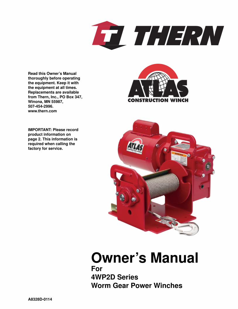
Read this Own er’s Man u al thor ough ly be fore op er at ing the equip ment. Keep it with the equip ment at all times. Re place ments are avail able from Thern, Inc., PO Box 347, Winona, MN 55987,507-454-2996.www.thern.com
IMPORTANT: Please record product information on page 2. This information is re quired when calling the fac to ry for service.
A8328D-0114
Owner’s Man ualFor 4WP2D SeriesWorm Gear Power Winches
Owner's Manual for Thern 4WP2D Series Worm Gear Power Winchespage 2
A8328D-0114
Two-Year Limited Warranty
Thern, Inc. warrants its products against defects in material or workmanship for two years from the date of purchase
by the original using buyer, or if this date cannot be established, the date the product was sold by Thern, Inc. to the
dealer. To make a claim under this war ran ty, contact the factory for an RGA number. The prod uct must be re turned,
pre paid, di rect ly to Thern, Inc., 5712 Industrial Park Road, Winona, Min ne so ta 55987. The fol low ing in for ma tion
must ac com pa ny the product: the RGA number, the date of pur chase, the de scrip tion of the claimed defect, and a com-
plete ex pla na tion of the circumstances involved. If the product is found to be defective, it will be re paired or re placed
free of charge, and Thern, Inc. will re im burse the ship ping cost within the con tig u ous USA.
This warranty does not cover any dam age due to accident, misuse, abuse, or negligence. Any alteration, repair or
mod i fi ca tion of the product outside the Thern, Inc. factory shall void this war ran ty. This warranty does not cover any
costs for removal of our product, down time, or any other incidental or con se quen tial costs or damages resulting from
the claimed defects. This war ran ty does not cover brake discs, as these are wear components and their life is sub ject to
use con di tions which vary be tween applications.
FACTORY AUTHORIZED REPAIR OR RE PLACE MENT AS PRO VID ED UNDER THIS WARRANTY IS THE
EXCLUSIVE REMEDY TO THE CON SUM ER. THERN, INC. SHALL NOT BE LIABLE FOR ANY INCIDEN-
TAL OR CON SE QUEN TIAL DAMAGES FOR BREACH OF ANY EXPRESS OR IMPLIED WARRANTY ON
THIS PRODUCT. EXCEPT TO THE EX TENT PROHIBITED BY AP PLI CA BLE LAW, ANY IMPLIED WAR-
RANTY OF MERCHANTABILITY OR FITNESS FOR A PAR TIC U LAR PURPOSE ON THIS PRODUCT IS
LIMITED IN DURATION TO THE DURATION OF THIS WAR RAN TY.
Some states do not allow the exclusion or limitation of incidental or con se quen tial damages, or allow lim i ta tions on
how long an implied warranty lasts, so the above limitation or ex clu sion may not apply to you. This war ran ty gives
you specifi c legal rights, and you may also have other rights which vary from state to state.
Note: Thern, Inc. reserves the right to change the design or discontinue the production of any product without
prior notice.
About This Manual
The Occupational Safety and Health Act of 1970 states that it is the employer’s
re spon si bil i ty to provide a workplace free of hazard. To this end, all equipment
should be installed, operated, and maintained in compliance with applicable trade,
industrial, federal, state, and local regulations. It is the equipment own er's re spon -
si bil i ty to ob tain copies of these regulations and to determine the suit abil i ty of the
equip ment to its intended use.
This Owner’s Manual, and warning labels attached to the equip ment, are to serve
as guidelines for hazard-free installation, op er a tion, and maintenance. They should
not be understood to prepare you for every pos si ble situation.
The information contained in this manual is applicable only to the Thern 4WP2D
Series Worm Gear Power Winches. Do not use this manual as a source of in for -
ma tion for any other equip ment.
The following symbols are used for emphasis throughout this man u al:
Failure to follow ‘WARNING!’ instructions may result in equipment dam age,
property damage, and/or serious personal injury.
Failure to follow ‘CAUTION!’ instructions may result in equipment damage,
prop er ty damage, and/or minor personal injury.
Important!
Failure to follow ‘important!’ instructions may result in poor per for mance of
the equipment.
Please record the following:
Date Purchased:
Model No.:
Serial No.:
This information is required when
calling the factory for service.
Owner's Manual for Thern 4WP2D Series Worm Gear Power Winches page 3
A8328D-0114
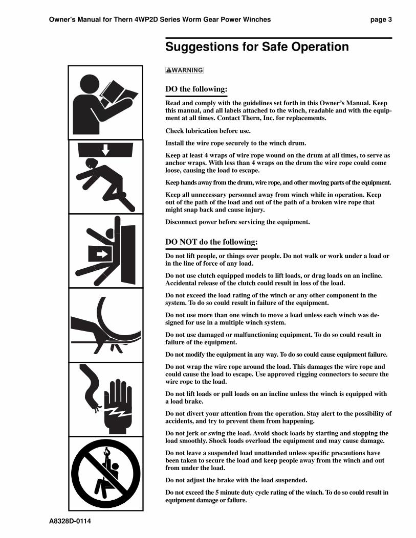
Suggestions for Safe Operation
DO the following:
Read and comply with the guidelines set forth in this Owner’s Manual. Keep this manual, and all labels attached to the winch, readable and with the equip-ment at all times. Contact Thern, Inc. for replacements.
Check lubrication before use.
Install the wire rope securely to the winch drum.
Keep at least 4 wraps of wire rope wound on the drum at all times, to serve as anchor wraps. With less than 4 wraps on the drum the wire rope could come loose, causing the load to escape.
Keep hands away from the drum, wire rope, and other moving parts of the equipment.
Keep all unnecessary personnel away from winch while in operation. Keep out of the path of the load and out of the path of a broken wire rope that might snap back and cause injury.
Disconnect power before servicing the equipment.
DO NOT do the following:
Do not lift people, or things over people. Do not walk or work under a load or in the line of force of any load.
Do not use clutch equipped models to lift loads, or drag loads on an incline. Accidental release of the clutch could result in loss of the load.
Do not exceed the load rating of the winch or any other component in the system. To do so could result in failure of the equipment.
Do not use more than one winch to move a load unless each winch was de-signed for use in a multiple winch system.
Do not use damaged or malfunctioning equipment. To do so could result in failure of the equipment.
Do not modify the equipment in any way. To do so could cause equipment failure.
Do not wrap the wire rope around the load. This damages the wire rope and could cause the load to escape. Use approved rigging connectors to secure the wire rope to the load.
Do not lift loads or pull loads on an incline unless the winch is equipped with a load brake.
Do not divert your attention from the operation. Stay alert to the possibility of accidents, and try to prevent them from happening.
Do not jerk or swing the load. Avoid shock loads by starting and stopping the load smoothly. Shock loads overload the equipment and may cause damage.
Do not leave a suspended load unattended unless specifi c precautions have been taken to secure the load and keep people away from the winch and out from under the load.
Do not adjust the brake with the load suspended.
Do not exceed the 5 minute duty cycle rating of the winch. To do so could result in
equipment damage or failure.
Owner's Manual for Thern 4WP2D Series Worm Gear Power Winchespage 4
A8328D-0114
1.1 Installing the Winch
Do not install the winch in an area defi ned as hazardous by the Na tion al Elec-
tric Code, unless installation in such an area has been thor ough ly ap proved.
Do not install the winch near corrosive chemicals, fl ammable materials, ex-
plo sives, or other elements that may damage the winch or injure the op er a tor.
Ad e quate ly protect the winch and the operator from such el e ments.
Position the winch so the operator can stand clear of the load, and out of the
path of a broken wire rope that could snap back and cause injury.
Attach the winch to a rigid and level foundation that will support the winch
and its load under all load conditions, including shock loading.
1.1.1 CONSULT APPLICABLE CODES AND REGULATIONS for specifi c
rules on installing the equipment.
1.1.2 LOCATE THE WINCH in an area clear of traffi c and obstacles. Make sure
the winch is accessible for main te nance and op er a tion.
1.1.3 LOCATE THE WINCH in an area with adequate temperatures. The winch is
rated for operation in ambient temperatures ranging from 0° to 100° F.
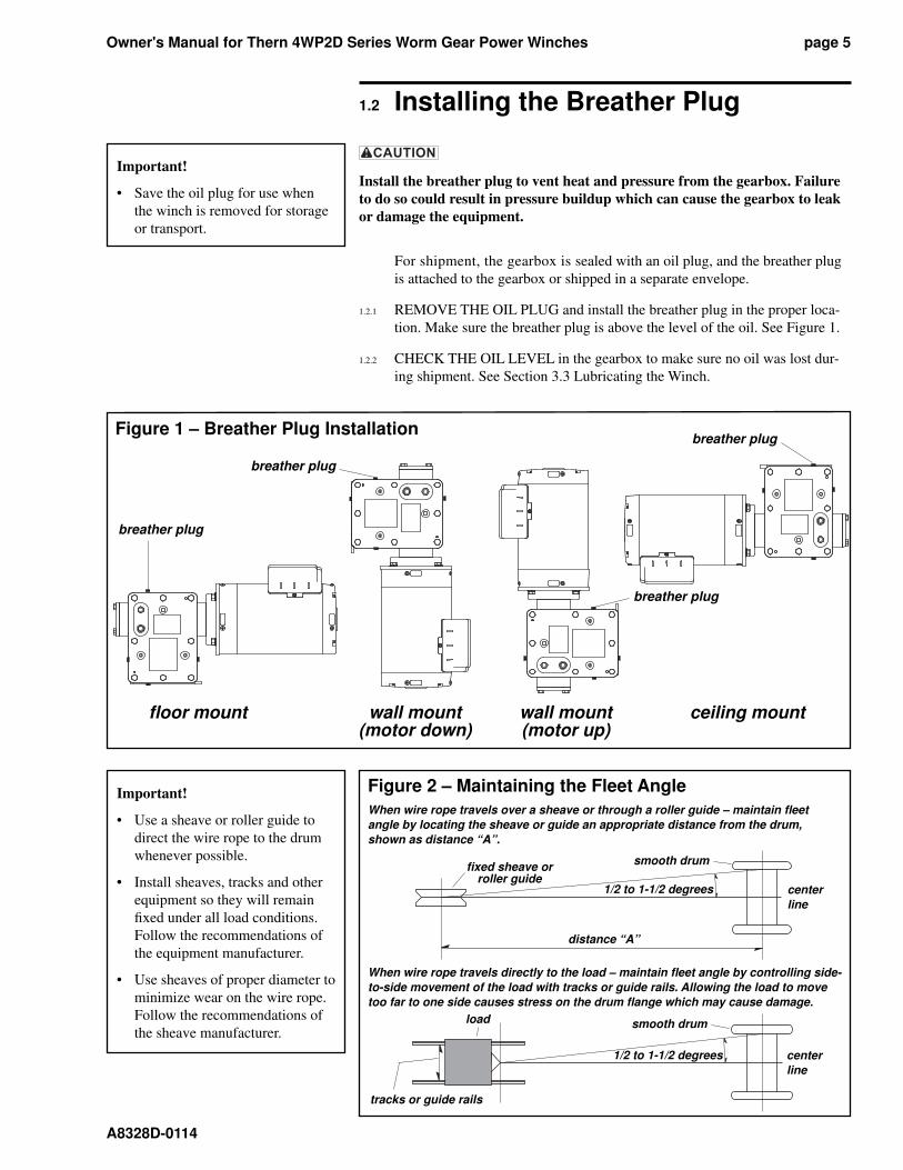
1.1.4 MAINTAIN A FLEET ANGLE between 1/2 and 1-1/2 degrees. The proper
fl eet angle minimizes wire rope damage by helping the wire rope wind uni-
form ly onto the drum. See Figure 2.
1.1.5 POSITION THE WINCH to allow access for proper lubrication.
1.1.6 FASTEN THE WINCH securely to the foundation.
a FOR STANDARD PRODUCTS referred to in this manual, use 3/8 - inch
coarse thread fasteners, grade 5 or better, torque dry to 30 ft lb without lubri-
cation. Make sure the winch is secured to a solid foundation able to support
the winch and the load under all conditions with design factors based on
accepted engineering practices.
b NON-STANDARD PRODUCTS that vary from the original design may
have different fastening requirements. Contact a structural engineer or
Thern, Inc. for this information.
TO COMPLY WITH LOCAL CODES, CONTACT A QUAL I FIED PRO FES -SION AL TO OBTAIN PROPER STRUCTURE OR FOUN DA TION SPEC I FI C-
A TIONS FOR THE MOUNTING OF THERN PROD UCTS.
Important!
• Inspect the winch immediately
following installation according
to the Instructions for Periodic
Inspection. This will give you
a record of the condition of the
winch with which to com pare
future inspections.
• A qualifi ed professional should
inspect or design the founda-
tion to insure that it will provide
adequate support.
• Locate the winch so it will be vis-
ible during the entire op er a tion.
• Do not weld the winch frame to
the foundation or support struc-
ture. Welding the frame may void
warranty, contact Thern, Inc. Use
fasteners as instructed.
Owner's Manual for Thern 4WP2D Series Worm Gear Power Winches page 5
A8328D-0114
1.2 Installing the Breather Plug
Install the breather plug to vent heat and pressure from the gearbox. Fail ure
to do so could result in pressure buildup which can cause the gearbox to leak
or damage the equipment.
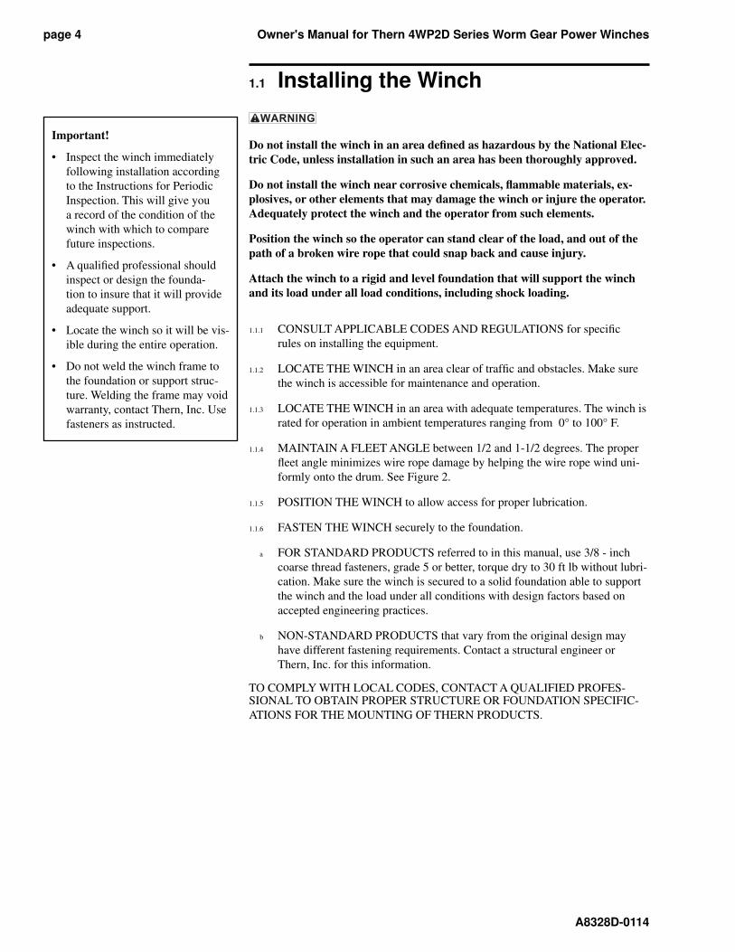
For shipment, the gearbox is sealed with an oil plug, and the breather plug
is attached to the gearbox or shipped in a separate en ve lope.
1.2.1 REMOVE THE OIL PLUG and install the breather plug in the proper lo ca-
tion. Make sure the breather plug is above the level of the oil. See Figure 1.
1.2.2 CHECK THE OIL LEVEL in the gearbox to make sure no oil was lost dur-
ing shipment. See Section 3.3 Lubricating the Winch.
Important!
• Use a sheave or roller guide to
direct the wire rope to the drum
whenever possible.
• Install sheaves, tracks and other
equipment so they will remain
fi xed under all load conditions.
Follow the recommendations of
the equipment manufacturer.
• Use sheaves of proper diameter to
minimize wear on the wire rope.
Follow the rec om men da tions of
the sheave manufacturer.
smooth drum
1/2 to 1-1/2 de grees
distance “A”
center
line
fi xed sheave or roller guide
Figure 2 – Maintaining the Fleet Angle
When wire rope travels over a sheave or through a roller guide – main tain fl eet
angle by locating the sheave or guide an appropriate distance from the drum,
shown as distance “A”.
When wire rope travels directly to the load – maintain fl eet angle by con trol ling side-
to-side movement of the load with tracks or guide rails. Allowing the load to move
too far to one side causes stress on the drum fl ange which may cause damage.
1/2 to 1-1/2 de grees center
line
smooth drum
tracks or guide rails
load
Important!
• Save the oil plug for use when
the winch is removed for storage
or transport.
Figure 1 – Breather Plug Installation
breather plug
breather plug
breather plug
fl oor mount wall mount wall mount ceiling mount (motor down) (motor up)
breather plug
Owner's Manual for Thern 4WP2D Series Worm Gear Power Winchespage 6
A8328D-0114
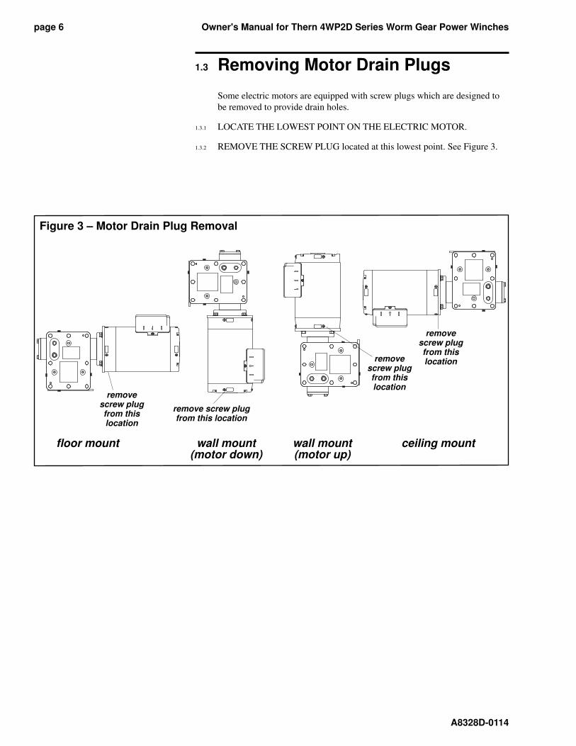
1.3 Removing Motor Drain Plugs
Some electric motors are equipped with screw plugs which are designed to
be removed to provide drain holes.
1.3.1 LOCATE THE LOWEST POINT ON THE ELECTRIC MOTOR.
1.3.2 REMOVE THE SCREW PLUG located at this lowest point. See Figure 3.
Figure 3 – Motor Drain Plug Removal
remove screw plug from this location
remove screw plug from this location
remove screw plug from this location
fl oor mount wall mount wall mount ceiling mount (motor down) (motor up)
remove screw plug from this location
Owner's Manual for Thern 4WP2D Series Worm Gear Power Winches page 7
A8328D-0114
Important!
• Use components rated for the
power supply you will be using.
• Always disconnect power when
the winch is not in use.
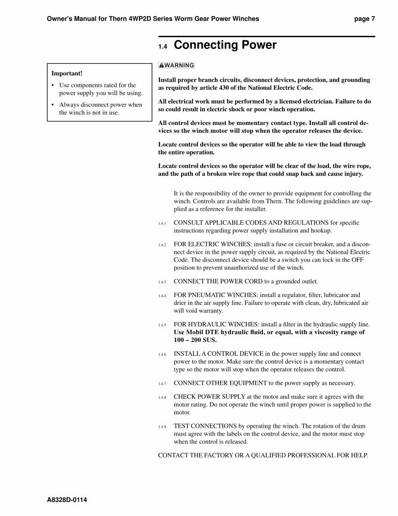
1.4 Connecting Power
Install proper branch circuits, disconnect devices, protection, and ground ing
as required by article 430 of the National Electric Code.
All electrical work must be performed by a licensed electrician. Failure to do
so could result in electric shock or poor winch operation.
All control devices must be momentary contact type. Install all control de-
vic es so the winch motor will stop when the operator releases the device.
Locate control devices so the operator will be able to view the load through
the entire operation.
Locate control devices so the operator will be clear of the load, the wire rope,
and the path of a broken wire rope that could snap back and cause injury.
It is the responsibility of the owner to provide equipment for con trol ling the
winch. Controls are available from Thern. The fol low ing guide lines are sup-
plied as a reference for the installer.
1.4.1 CONSULT APPLICABLE CODES AND REGULATIONS for specifi c
instructions regarding power supply installation and hookup.
1.4.2 FOR ELECTRIC WINCHES: install a fuse or circuit breaker, and a dis con -
nect device in the power supply circuit, as re quired by the National Elec tric
Code. The disconnect device should be a switch you can lock in the OFF
position to prevent unauthorized use of the winch.
1.4.3 CONNECT THE POWER CORD to a grounded outlet.
1.4.4 FOR PNEUMATIC WINCHES: install a regulator, fi lter, lubricator and
drier in the air supply line. Failure to operate with clean, dry, lubricated air
will void warranty.
1.4.5 FOR HYDRAULIC WINCHES: install a fi lter in the hydraulic supply line.
Use Mobil DTE hydraulic fl uid, or equal, with a viscosity range of
100 – 200 SUS.
1.4.6 INSTALL A CONTROL DEVICE in the power supply line and connect
power to the motor. Make sure the control device is a momentary contact
type so the motor will stop when the operator releases the control.
1.4.7 CONNECT OTHER EQUIPMENT to the power supply as necessary.
1.4.8 CHECK POWER SUPPLY at the motor and make sure it agrees with the
motor rating. Do not operate the winch until proper power is sup plied to the
motor.
1.4.9 TEST CONNECTIONS by operating the winch. The rotation of the drum
must agree with the labels on the control device, and the motor must stop
when the control is released.
CONTACT THE FACTORY OR A QUALIFIED PROFESSIONAL FOR HELP.
Owner's Manual for Thern 4WP2D Series Worm Gear Power Winchespage 8
A8328D-0114
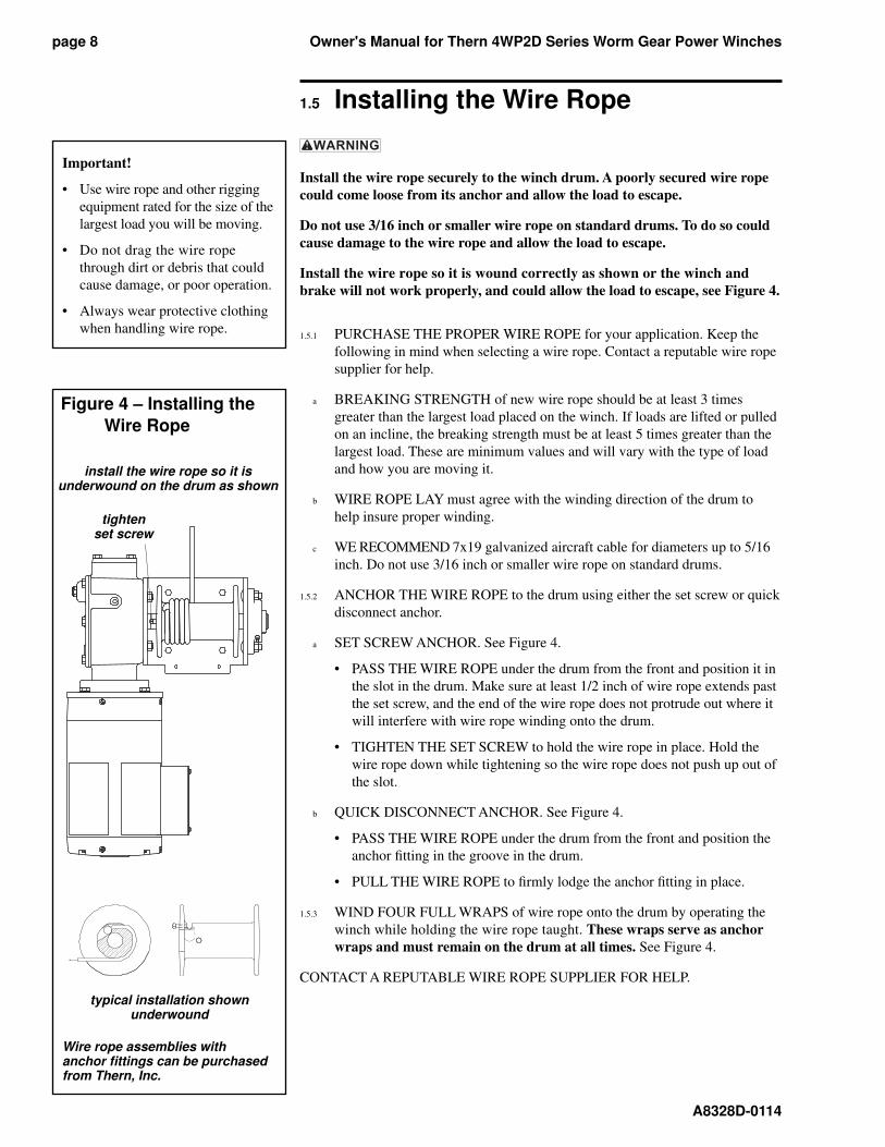
1.5 Installing the Wire Rope
Install the wire rope securely to the winch drum. A poorly secured wire rope
could come loose from its anchor and allow the load to escape.
Do not use 3/16 inch or smaller wire rope on standard drums. To do so could
cause damage to the wire rope and allow the load to escape.
Install the wire rope so it is wound correctly as shown or the winch and
brake will not work properly, and could allow the load to escape, see Figure 4.
1.5.1 PURCHASE THE PROPER WIRE ROPE for your application. Keep the
following in mind when selecting a wire rope. Contact a reputable wire rope
supplier for help.
a BREAKING STRENGTH of new wire rope should be at least 3 times
great er than the largest load placed on the winch. If loads are lifted or pulled
on an incline, the breaking strength must be at least 5 times greater than the
larg est load. These are minimum values and will vary with the type of load
and how you are mov ing it.
b WIRE ROPE LAY must agree with the winding direction of the drum to
help insure proper winding.
c WE RECOMMEND 7x19 galvanized aircraft cable for diameters up to 5/16
inch. Do not use 3/16 inch or smaller wire rope on standard drums.
1.5.2 ANCHOR THE WIRE ROPE to the drum using either the set screw or quick
dis con nect anchor.
a SET SCREW ANCHOR. See Figure 4.
• PASS THE WIRE ROPE under the drum from the front and po si tion it in
the slot in the drum. Make sure at least 1/2 inch of wire rope ex tends past
the set screw, and the end of the wire rope does not pro trude out where it
will in ter fere with wire rope wind ing onto the drum.
• TIGHTEN THE SET SCREW to hold the wire rope in place. Hold the
wire rope down while tight en ing so the wire rope does not push up out of
the slot.
b QUICK DISCONNECT AN CHOR. See Figure 4.
• PASS THE WIRE ROPE under the drum from the front and position the
anchor fi tting in the groove in the drum.
• PULL THE WIRE ROPE to fi rmly lodge the anchor fi t ting in place.
1.5.3 WIND FOUR FULL WRAPS of wire rope onto the drum by op er at ing the
winch while holding the wire rope taught. These wraps serve as anchor
wraps and must remain on the drum at all times. See Figure 4.
CONTACT A REPUTABLE WIRE ROPE SUPPLIER FOR HELP.
Important!
• Use wire rope and other rigging
equipment rated for the size of the
largest load you will be moving.
• Do not drag the wire rope
through dirt or debris that could
cause dam age, or poor operation.
• Always wear protective clothing
when handling wire rope.
Figure 4 – Installing the
Wire Rope
install the wire rope so it isunderwound on the drum as shown
typical installation shownunderwound
tighten set screw
Wire rope assemblies with anchor fi ttings can be purchased from Thern, Inc.
Owner's Manual for Thern 4WP2D Series Worm Gear Power Winches page 9
A8328D-0114
Important!
• Limit nonuniform winding by
keeping tension on the wire rope
and by maintaining the proper
fl eet angle.
• To help insure rated per for mance,
make sure power supply at the
motor is equal to the motor’s
power rating.
• It is your responsibility to detect
and account for different fac-
tors affecting the condition and
per for mance of the equipment.
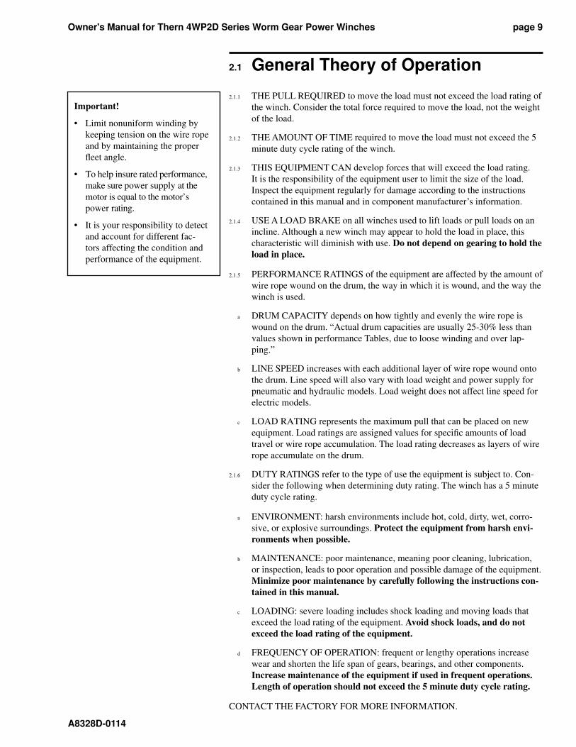
2.1 General Theory of Operation
2.1.1 THE PULL REQUIRED to move the load must not exceed the load rating of
the winch. Consider the total force required to move the load, not the weight
of the load.
2.1.2 THE AMOUNT OF TIME required to move the load must not exceed the 5
minute duty cycle rating of the winch.
2.1.3 THIS EQUIPMENT CAN develop forces that will exceed the load rating.
It is the responsibility of the equipment user to limit the size of the load.
In spect the equip ment reg u lar ly for damage according to the instructions
contained in this manual and in component manufacturer’s information.
2.1.4 USE A LOAD BRAKE on all winches used to lift loads or pull loads on an
incline. Although a new winch may appear to hold the load in place, this
char ac ter is tic will diminish with use. Do not depend on gearing to hold the
load in place.
2.1.5 PERFORMANCE RATINGS of the equipment are affected by the amount of
wire rope wound on the drum, the way in which it is wound, and the way the
winch is used.
a DRUM CAPACITY depends on how tightly and evenly the wire rope is
wound on the drum. “Actual drum capacities are usually 25-30% less than
values shown in performance Tables, due to loose winding and over lap-
ping.”
b LINE SPEED increases with each additional layer of wire rope wound onto
the drum. Line speed will also vary with load weight and power supply for
pneu mat ic and hydraulic models. Load weight does not affect line speed for
electric models.
c LOAD RATING represents the maximum pull that can be placed on new
equip ment. Load ratings are assigned values for specifi c amounts of load
travel or wire rope accumulation. The load rating decreases as layers of wire
rope ac cu mu late on the drum.
2.1.6 DUTY RATINGS refer to the type of use the equipment is sub ject to. Con-
sid er the following when determining duty rating. The winch has a 5 minute
duty cycle rating.
a ENVIRONMENT: harsh environments include hot, cold, dirty, wet, cor ro-
sive, or explosive surroundings. Protect the equip ment from harsh en vi-
ron ments when possible.
b MAINTENANCE: poor maintenance, meaning poor cleaning, lubrication,
or inspection, leads to poor operation and possible damage of the equip ment.
Minimize poor maintenance by carefully following the in struc tions con-
tained in this manual.
c LOADING: severe loading includes shock loading and moving loads that
ex ceed the load rating of the equipment. Avoid shock loads, and do not
ex ceed the load rating of the equip ment.
d FREQUENCY OF OPERATION: frequent or lengthy operations increase
wear and shorten the life span of gears, bearings, and other components.
Increase maintenance of the equipment if used in frequent operations.
Length of operation should not exceed the 5 minute duty cycle rating.
CONTACT THE FACTORY FOR MORE INFORMATION.
Owner's Manual for Thern 4WP2D Series Worm Gear Power Winchespage 10
A8328D-0114
2.2 Breaking-In the Winch
2.2.1 BREAK-IN OCCURS during the fi rst 30 to 60 minutes of operation. Dur ing
break-in, mating surfaces become polished, and clearances in crease. This is
de sired for effi cient operation of bearings and gears.
2.2.2 INSPECT THE WINCH following break-in according to the Instructions for
Periodic Inspection. See Section 3.4 Inspecting the Equipment.
2.3 Preparing for Operation
2.3.1 CONSIDER THE OPERATION. Do not begin until you are sure you can
perform the entire operation without hazard.
2.3.2 INSPECT ALL COMPONENTS of the system.
a INSPECT THE WINCH and other equipment according to the Instructions
for Frequent Inspection.
b OPERATORS must be in good health, alert, thoroughly trained in op er at ing
the equipment, and properly clothed (hard hat, safety shoes and safety
glass es, no loose clothing).
c THE LOAD must be clear of other objects and free to move. Make sure the
load will not tip, spin, roll away, or in any way move uncontrollably.
2.3.3 KNOW YOUR LOAD and make sure you do not exceed the load rating of
the winch or any other equipment in the system.
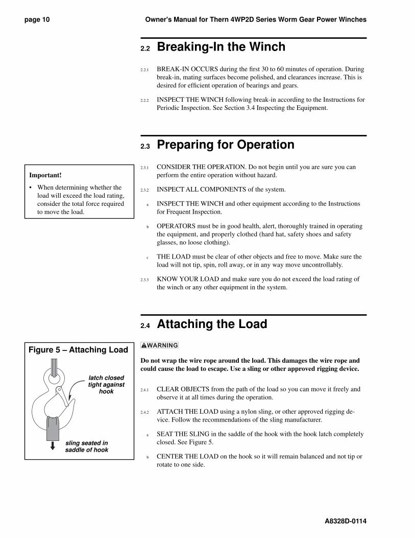
2.4 Attaching the Load
Do not wrap the wire rope around the load. This damages the wire rope and
could cause the load to escape. Use a sling or other approved rigging device.
2.4.1 CLEAR OBJECTS from the path of the load so you can move it freely and
observe it at all times during the operation.
2.4.2 ATTACH THE LOAD using a nylon sling, or other approved rigging de-
vice. Fol low the recommendations of the sling manufacturer.
a SEAT THE SLING in the saddle of the hook with the hook latch com plete ly
closed. See Figure 5.
b CENTER THE LOAD on the hook so it will remain balanced and not tip or
rotate to one side.
Important!
• When determining whether the
load will exceed the load rating,
consider the total force required
to move the load.
Figure 5 – Attaching Load
latch closed tight against
hook
sling seated in saddle of hook
Owner's Manual for Thern 4WP2D Series Worm Gear Power Winches page 11
A8328D-0114
2.5 Moving the Load
2.5.1 MOVE THE LOAD slowly and smoothly, only a small distance at fi rst.
Make sure the load is balanced and securely attached before continuing.
2.5.2 USE THE CONTROL DEVICE to operate the winch. The control device
should be momentary contact type, so the winch will stop when the op er a tor
releases the control.
2.5.3 DO NOT EXCEED DUTY CYCLE RATING of the winch. This equipment
is rated for a 5 minute duty cycle.
2.5.4 OBSERVE THE WIRE ROPE as it winds onto the drum. If it becomes
loose, uneven, or overlapped, stop the operation and rewind the wire rope
before continuing. Continued operation with overlapped or uneven wire
rope can damage the wire rope and shorten its life.
2.5.5 ALLOW THE WINCH TO COOL DOWN to ambient temperature in rest
periods between op er a tions.
2.5.6 OBSERVE THE GEARBOX AND BRAKE during operation for signs of
overheating. Fre quent overheating may be a sign of damage, or may
indicate the need for a larger winch.
a WATCH FOR SMOKE, the smell of burnt oil, and other signs of over-
heat ing. Use a thermocouple or other device to monitor gearbox temperature.
The temperature of the oil should not exceed 150° F.
b STOP THE OPERATION if the gearbox or brake overheats, and allow the
winch to cool until it reaches ambient temperature. Continued operation
may cause dam age.
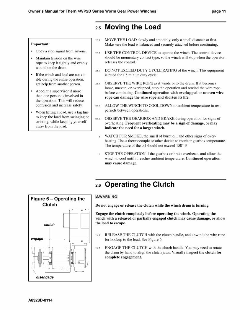
2.6 Operating the Clutch
Do not engage or release the clutch while the winch drum is turning.
Engage the clutch completely before operating the winch. Operating the
winch with a released or partially engaged clutch may cause damage, or allow
the load to escape.
2.6.1 RELEASE THE CLUTCH with the clutch handle, and unwind the wire rope
for hookup to the load. See Figure 6.
2.6.2 ENGAGE THE CLUTCH with the clutch handle. You may need to ro tate
the drum by hand to align the clutch jaws. Visually inspect the clutch for
com plete engagement.
Important!
• Obey a stop signal from anyone.
• Maintain tension on the wire
rope to keep it tightly and evenly
wound on the drum.
• If the winch and load are not vis-
ible during the entire op er a tion,
get help from another person.
• Appoint a supervisor if more
than one person is involved in
the operation. This will reduce
con fu sion and increase safety.
• When lifting a load, use a tag line
to keep the load from swinging or
twist ing, while keeping yourself
away from the load.
Figure 6 – Operating the
Clutch
disengage
clutch
engage
Owner's Manual for Thern 4WP2D Series Worm Gear Power Winchespage 12
A8328D-0114
2.7 Emergency Operation
(for models equipped with this feature)
Do not adjust the brake with the load suspended. Accidental release of the
brake could allow the load to escape.
Do not leave a suspended load unattended unless specifi c precautions have
been taken to secure the load and keep unnecessary personnel away from the
winch and from under the load.
2.7.1 IN CASE OF POWER FAILURE, turn the control device to OFF and DIS-
CONNECT electric power. Leave electric power DISCONNECTED.
2.7.2 MAKE SURE SAFETY PRECAUTIONS have been taken to secure the load
and keep unnecessary personnel away from the winch and from under the
load while operating the emergency hand crank.
2.7.3 IF EQUIPPED WITH A BRAKE MOTOR you must disengage the brake on
the motor before using the emergency hand crank. Operating the emergency
hand crank with the brake on the motor engaged could result in equipment
damage or failure.
a It is recommended for two people to operate the winch using the emergency
hand crank.
b If the winch is equipped with a brake motor, assign one person to operate the
hand crank while the other is assigned to operate the brake. Have control of
the hand crank before disengaging the brake on the motor. Accidental re-
lease of the brake could allow the load to escape.
c If the winch is not equipped with a brake motor, assign one person to operate
the hand crank while the other is assigned to observe and control the load.
d Always follow the brake manufacturers operating instructions for engaging
or disengaging the brake.
2.7.4 DO NOT USE AN IMPACT WRENCH to operate the emergency hand
crank option of the winch. To do so could result in equipment damage or
failure. Use a drill-motor.
2.7.5 DO NOT EXCEED THE 5 MINUTE DUTY CYCLE rating of the winch if
operating with a drill-motor and do not operate the winch with a drill-motor
that exceeds 400 rpm. To do so could result in equipment damage or failure.
2.7.6 ENGAGE THE BRAKE and remove the handle or drill-motor before operat-
ing the winch using electric power.
ANY QUESTIONS ON OPERATING THE EMERGENCY HAND CRANK
OPTION OR WINCH APPLICATION CONTACT THERN, INC.
Owner's Manual for Thern 4WP2D Series Worm Gear Power Winches page 13
A8328D-0114
3.1 Cleaning the Winch
Clean the winch to remove dirt and help prevent rust and cor ro sion.
3.1.1 CLEAN THE WINCH every 6 months or whenever it is dirty.
a WIPE ALL EQUIPMENT to remove dirt and grease.
b LEAVE A LIGHT FILM of oil on all surfaces to protect them against rust
and corrosion.
c WIPE OFF excessive amounts of oil to avoid the accumulation of dirt.
3.1.2 REMOVE ALL UNNECESSARY OBJECTS from the area sur round ing the
winch.
3.2 Adjusting the Brake
Do not adjust the brake with the load suspended. Accidental release of the
brake could allow the load to escape.
3.2.1 ADJUST THE BRAKE whenever it appears to need adjustment, or at least
every 3 months.
3.2.2 CHECK THE ELECTRIC BRAKE ON THE MOTOR (if equipped) by
operating the winch with a test load equal to the winch load rating.
a DISENGAGE THE ELECTRICAL BRAKE under no load. See Figure 7a.
b RAISE THE LOAD, then lower it and stop it about one foot off the ground.
b OBSERVE THE LOAD when stopped. If it continues to coast or creep, the
brake needs adjustment. Refer to the brake manufacturer's instructions, or
contact the factory for assistance.
d RE-ENGAGE THE MECHANICAL BRAKE by following the instructions
below.
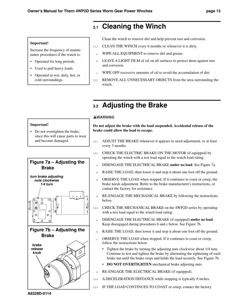
3.2.3 CHECK THE MECHANICAL BRAKE on the 4WP2D series by operating
with a test load equal to the winch load rating:
a DISENGAGE THE ELECTRICAL BRAKE (if equipped) under no load.
Keep disengaged during procedures b and c below. See Figure 7b.
b RAISE THE LOAD, then lower it and stop it about one foot off the ground.
c OBSERVE THE LOAD when stopped. If it continues to coast or creep, follow the instructions below:
• Tighten the brake by turning the adjusting nuts clockwise about 1/4 turn.
Continue to test and tighten the brake by alternating the tightening of each
brake nut until the brake stops and holds the load securely. See Figure 7b.
• DO NOT OVERTIGHTEN mechanical brake adjusting nuts.
d RE-ENGAGE THE ELECTRICAL BRAKE (if equipped).
3.2.4 A DECELERATION DISTANCE while stopping is typically 6 inches.
3.2.5 IF THE LOAD CONTINUES TO COAST or creep, contact the factory.
Important!
Increase the frequency of main te -
nance procedures if the winch is:
• Operated for long periods.
• Used to pull heavy loads.
• Operated in wet, dirty, hot, or
cold surroundings.
Important!
• Do not overtighten the brake,
since this will cause parts to wear
and become damaged.
Figure 7a – Adjusting the
Brake
Figure 7b – Adjusting the
Brake
turn brake adjusting nuts clock wise
1/4 turn
brakereleaseknob
Owner's Manual for Thern 4WP2D Series Worm Gear Power Winchespage 14
A8328D-0114
3.3 Lubricating the Winch
Make sure the breather is clean and open to vent heat and pres sure. Poor ven-
tilation may cause overheating and result in equipment damage.
Check the gearbox for proper level before operating. Too much or too little oil
will cause overheating and result in equipment damage.
Lubricate the winch prop er ly to help protect it from wear and rust. Read the
following in struc tions carefully.
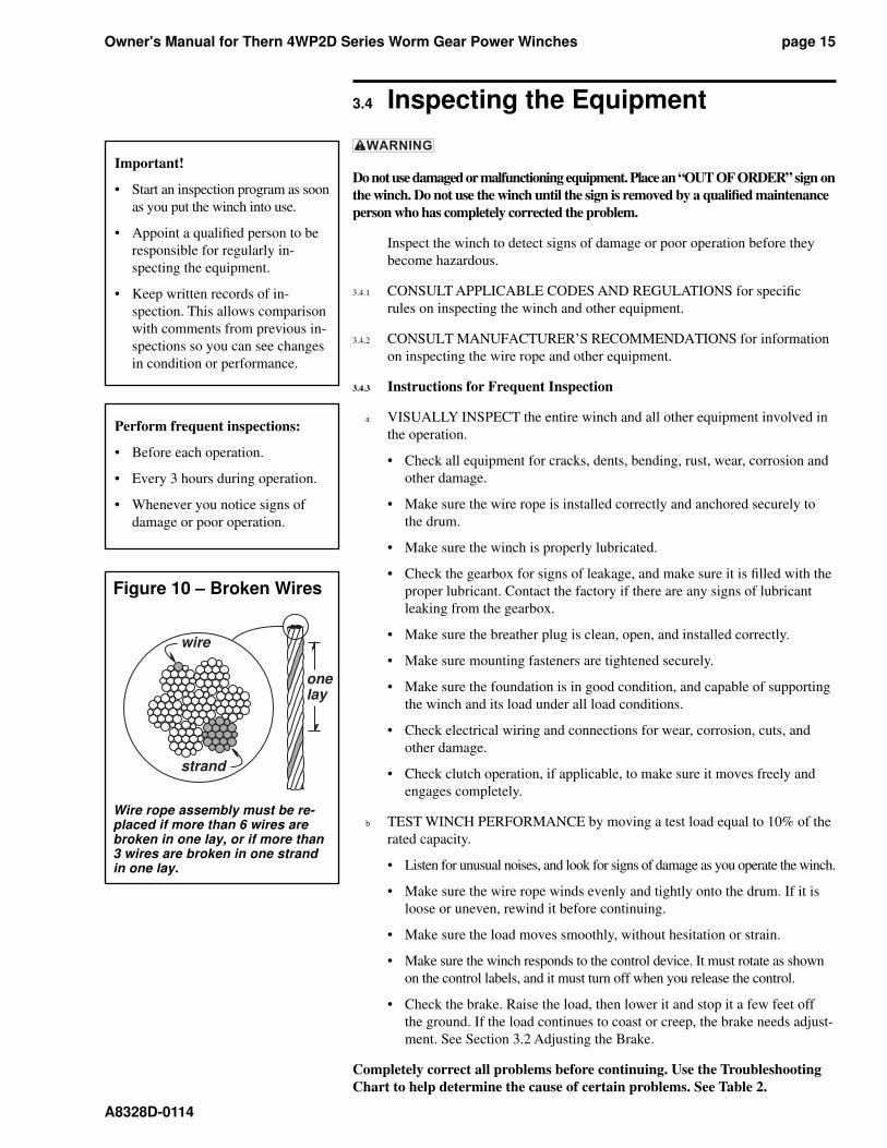
3.3.1 FOR 4WP2D SERIES, the winch is shipped from the factory with the proper
amount (44 ounces) of Mobilgear 600 XP220 lubricant in the gearbox. Lu-
bricate the winch as follows. See Figure 9.
3.3.2 MOTOR BEARINGS are typically lubricated for life by the manufacturer.
a REPLACE MOTOR BEARINGS if the motor is disassembled for any rea son.
b REFER TO MOTOR MANUFACTURER’S INFORMATION for specifi c
in struc tions regarding motor lubrication.
3.3.3 CHECK OIL LEVEL before every operation and every 10 hours during op-
eration. Remove the level check plug and make sure oil is even with the plug
hole. Add oil to the gearbox if necessary. Do not use synthetic lubricants
and do not mix different lu bri cants. See Figure 9.
3.3.4 CHANGE GEARBOX OIL at least every 6 months, or whenever it is dirty
or con tam i nat ed. Remove the drain plug to drain oil from the gear box. See
Figure 9.
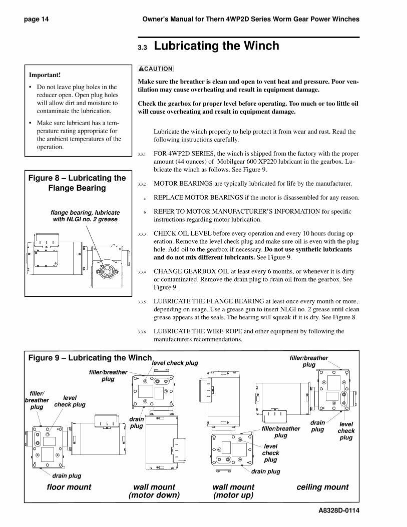
3.3.5 LUBRICATE THE FLANGE BEARING at least once ev ery month or more,
depending on usage. Use a grease gun to insert NLGI no. 2 grease until clean
grease appears at the seals. The bear ing will squeak if it is dry. See Figure 8.
3.3.6 LUBRICATE THE WIRE ROPE and other equipment by following the
manufacturers recommendations.
Figure 8 – Lubricating the
Flange Bearing
fl ange bearing, lubricate with NLGI no. 2 grease
Important!
• Do not leave plug holes in the
reducer open. Open plug holes
will allow dirt and moisture to
con tam i nate the lubrication.
• Make sure lubricant has a tem-
per a ture rating appropriate for
the ambient temperatures of the
operation.
Figure 9 – Lubricating the Winch
fl oor mount wall mount wall mount ceiling mount (motor down) (motor up)
fi ller/breather
plug
level check plug
drain plug
fi ller/breather plug
level check plug
drain plug fi ller/breather
plug
level check plug
drain plug
fi ller/breather plug
drain plug
level check plug
Owner's Manual for Thern 4WP2D Series Worm Gear Power Winches page 15
A8328D-0114
3.4 Inspecting the Equipment
Do not use damaged or malfunctioning equipment. Place an “OUT OF OR DER” sign on
the winch. Do not use the winch until the sign is re moved by a qual i fi ed maintenance
person who has completely corrected the prob lem.
Inspect the winch to detect signs of damage or poor operation before they
be come hazardous.
3.4.1 CONSULT APPLICABLE CODES AND REGULATIONS for specifi c
rules on inspecting the winch and other equipment.
3.4.2 CONSULT MANUFACTURER’S RECOMMENDATIONS for in for ma tion
on in spect ing the wire rope and other equipment.
3.4.3 In struc tions for Frequent Inspection
a VISUALLY INSPECT the entire winch and all other equipment involved in
the operation.
• Check all equipment for cracks, dents, bending, rust, wear, corrosion and
other damage.
• Make sure the wire rope is installed correctly and anchored securely to
the drum.
• Make sure the winch is properly lubricated.
• Check the gearbox for signs of leakage, and make sure it is fi lled with the
proper lubricant. Contact the factory if there are any signs of lubricant
leaking from the gearbox.
• Make sure the breather plug is clean, open, and installed correctly.
• Make sure mounting fasteners are tightened securely.
• Make sure the foundation is in good condition, and capable of supporting
the winch and its load under all load conditions.
• Check electrical wiring and connections for wear, corrosion, cuts, and
other damage.
• Check clutch operation, if applicable, to make sure it moves freely and
engages com plete ly.
b TEST WINCH PERFORMANCE by moving a test load equal to 10% of the
rated capacity.
• Listen for unusual noises, and look for signs of damage as you operate the winch.
• Make sure the wire rope winds evenly and tightly onto the drum. If it is
loose or uneven, rewind it before continuing.
• Make sure the load moves smoothly, without hesitation or strain.
• Make sure the winch responds to the control device. It must rotate as shown
on the control labels, and it must turn off when you release the control.
• Check the brake. Raise the load, then lower it and stop it a few feet off
the ground. If the load continues to coast or creep, the brake needs ad just-
ment. See Section 3.2 Adjusting the Brake.
Completely correct all problems before continuing. Use the Trou ble shoot ing
Chart to help determine the cause of certain problems. See Table 2.
Important!
• Start an inspection program as soon
as you put the winch into use.
• Appoint a qualifi ed person to be
responsible for regularly in-
spect ing the equipment.
• Keep written records of in-
spec tion. This allows comparison
with com ments from previous in-
spec tions so you can see chang es
in con di tion or per for mance.
Perform frequent inspections:
• Before each operation.
• Every 3 hours during operation.
• Whenever you notice signs of
damage or poor operation.
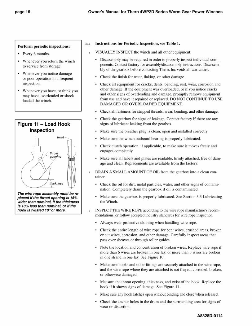
wire
strand
onelay
Figure 10 – Broken Wires
Wire rope assembly must be re- placed if more than 6 wires are bro ken in one lay, or if more than 3 wires are broken in one strand in one lay.
Owner's Manual for Thern 4WP2D Series Worm Gear Power Winchespage 16
A8328D-0114
3.4.4 Instructions for Periodic Inspection, see Table 1.
a VISUALLY INSPECT the winch and all other equipment.
• Disassembly may be required in order to properly inspect individual com-
ponents. Contact factory for assembly/disassembly instructions. Disassem-
bly of the gearbox before contacting Thern, Inc voids all warranties.
• Check the fi nish for wear, fl aking, or other damage.
• Check all equipment for cracks, dents, bending, rust, wear, corrosion and
other damage. If the equipment was overloaded, or if you notice cracks
and other signs of overloading and damage, promptly remove equipment
from use and have it repaired or replaced. DO NOT CONTINUE TO USE
DAMAGED OR OVERLOADED EQUIPMENT.
• Check all fasteners for stripped threads, wear, bending, and other dam age.
• Check the gearbox for signs of leakage. Contact factory if there are any
signs of lubricant leaking from the gearbox.
• Make sure the breather plug is clean, open and installed correctly.
• Make sure the winch outboard bearing is properly lubricated.
• Check clutch operation, if applicable, to make sure it moves freely and
engages com plete ly.
• Make sure all labels and plates are readable, fi rmly attached, free of dam-
age and clean. Replacements are available from the factory.
b DRAIN A SMALL AMOUNT OF OIL from the gearbox into a clean con-
tain er.
• Check the oil for dirt, metal particles, water, and other signs of con tam i-
na tion. Completely drain the gearbox if oil is con tam i nat ed.
• Make sure the gearbox is properly lubricated. See Section 3.3 Lubricating
the Winch.
c INSPECT THE WIRE ROPE according to the wire rope manufacture’s recom-
mendations, or follow accepted industry standards for wire rope inspection.
• Always wear protective clothing when handling wire rope.
• Check the entire length of wire rope for bent wires, crushed areas, bro ken
or cut wires, corrosion, and other damage. Carefully inspect areas that
pass over sheaves or through roller guides.
• Note the location and concentration of broken wires. Replace wire rope if
more than 6 wires are broken in one lay, or more than 3 wires are bro ken
in one strand in one lay. See Figure 10.
• Make sure hooks and other fi ttings are securely attached to the wire rope,
and the wire rope where they are attached is not frayed, cor rod ed, bro ken,
or otherwise damaged.
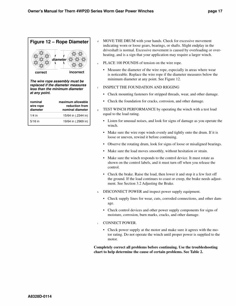
• Measure the throat opening, thickness, and twist of the hook. Replace the
hook if it shows signs of damage. See Figure 11.
• Make sure any hook latches open without binding and close when released.
• Check the anchor holes in the drum and the surrounding area for signs of
wear or distortion.
Perform periodic inspections:
• Every 6 months.
• Whenever you return the winch
to service from storage.
• Whenever you notice damage
or poor operation in a frequent
in spec tion.
• Whenever you have, or think you
may have, overloaded or shock
loaded the winch.
twist
throat opening
thickness
Figure 11 – Load Hook
Inspection
The wire rope assembly must be re-placed if the throat opening is 15% wider than nominal, if the thick ness is 10% less than nominal, or if the hook is twisted 10° or more.
Owner's Manual for Thern 4WP2D Series Worm Gear Power Winches page 17
A8328D-0114
d MOVE THE DRUM with your hands. Check for excessive movement
indicating worn or loose gears, bearings, or shafts. Slight endplay in the
driveshaft is normal. Excessive movement is caused by overloading or over-
heating, and is a sign that your application may require a larger winch.
e PLACE 100 POUNDS of tension on the wire rope.
• Measure the diameter of the wire rope, especially in areas where wear
is noticeable. Replace the wire rope if the diameter measures below the
minimum diameter at any point. See Figure 12.
f INSPECT THE FOUNDATION AND RIGGING
• Check mounting fasteners for stripped threads, wear, and other damage.
• Check the foundation for cracks, corrosion, and other damage.
g TEST WINCH PERFORMANCE by operating the winch with a test load
equal to the load rating.
• Listen for unusual noises, and look for signs of damage as you operate the
winch.
• Make sure the wire rope winds evenly and tightly onto the drum. If it is
loose or uneven, rewind it before continuing.
• Observe the rotating drum, look for signs of loose or misaligned bear ings.
• Make sure the load moves smoothly, without hesitation or strain.
• Make sure the winch responds to the control device. It must rotate as
shown on the control labels, and it must turn off when you release the
control.
• Check the brake. Raise the load, then lower it and stop it a few feet off
the ground. If the load continues to coast or creep, the brake needs ad just-
ment. See Section 3.2 Adjusting the Brake.
h DISCONNECT POWER and inspect power supply equipment.
• Check supply lines for wear, cuts, corroded connections, and other dam-
age.
• Check control devices and other power supply components for signs of
moisture, corrosion, burn marks, cracks, and other damage.
i CONNECT POWER.
• Check power supply at the motor and make sure it agrees with the mo-
tor rating. Do not operate the winch until proper power is supplied to the
motor.
Completely correct all problems before continuing. Use the trou ble shoot ing
chart to help determine the cause of certain problems. See Table 2.
correct incorrect
Figure 12 – Rope Diameter
diameter
The wire rope assembly must be replaced if the diameter measures less than the minimum diameter at any point.
nominal maximum allowable
wire rope reduction from
diameter nominal diameter
1/4 in 15/64 in (.2344 in)
5/16 in 19/64 in (.2969 in)
Owner's Manual for Thern 4WP2D Series Worm Gear Power Winchespage 18
A8328D-0114
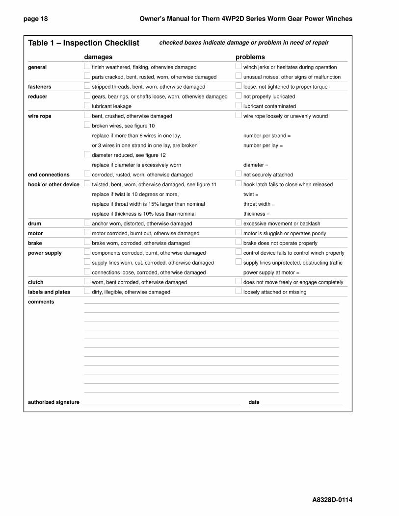
Table 1 – Inspection Checklist
damages problems
general fi nish weathered, fl aking, otherwise damaged winch jerks or hesitates during operation
parts cracked, bent, rusted, worn, otherwise damaged unusual noises, other signs of malfunction
fasteners stripped threads, bent, worn, otherwise damaged loose, not tightened to proper torque
reducer gears, bearings, or shafts loose, worn, otherwise damaged not properly lubricated
lubricant leakage lubricant contaminated
wire rope bent, crushed, otherwise damaged wire rope loosely or unevenly wound
broken wires, see fi gure 10
replace if more than 6 wires in one lay, number per strand =
or 3 wires in one strand in one lay, are broken number per lay =
diameter reduced, see fi gure 12
replace if diameter is excessively worn diameter =
end connections corroded, rusted, worn, otherwise damaged not securely attached
hook or other device twisted, bent, worn, otherwise damaged, see fi gure 11 hook latch fails to close when released
replace if twist is 10 degrees or more, twist =
replace if throat width is 15% larger than nominal throat width =
replace if thickness is 10% less than nominal thickness =
drum anchor worn, distorted, otherwise damaged excessive movement or backlash
motor motor corroded, burnt out, otherwise damaged motor is sluggish or operates poorly
brake brake worn, corroded, otherwise damaged brake does not operate properly
power supply components corroded, burnt, otherwise damaged control device fails to control winch properly
supply lines worn, cut, corroded, otherwise damaged supply lines unprotected, obstructing traffi c
connections loose, corroded, otherwise damaged power supply at motor =
clutch worn, bent corroded, otherwise damaged does not move freely or engage completely
labels and plates dirty, illegible, otherwise damaged loosely attached or missing
comments
authorized signature date
checked boxes indicate damage or problem in need of repair
Owner's Manual for Thern 4WP2D Series Worm Gear Power Winches page 19
A8328D-0114
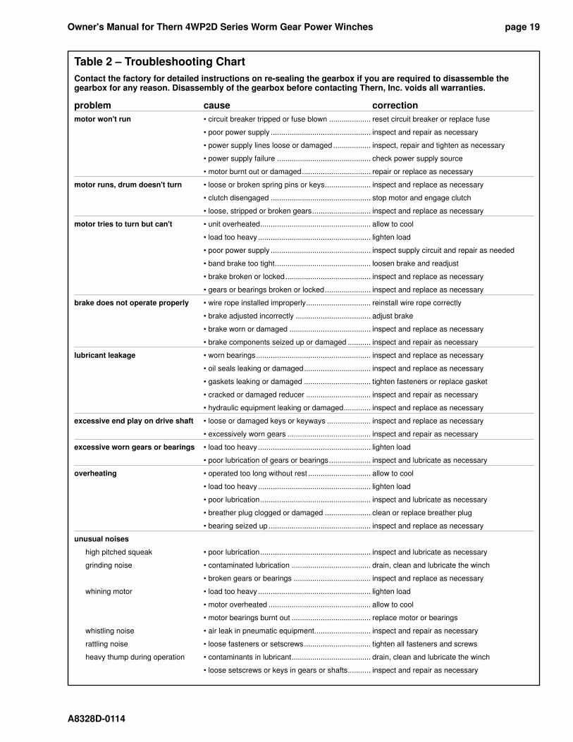
Table 2 – Troubleshooting Chart
Contact the factory for detailed instructions on re-sealing the gearbox if you are required to disassemble the gearbox for any reason. Disassembly of the gearbox before contacting Thern, Inc. voids all warranties.
problem cause correction
motor won't run • circuit breaker tripped or fuse blown .................... reset circuit breaker or replace fuse
• poor power supply ................................................ inspect and repair as necessary
• power supply lines loose or damaged .................. inspect, repair and tighten as necessary
• power supply failure ............................................. check power supply source
• motor burnt out or damaged ................................. repair or replace as necessary
motor runs, drum doesn't turn • loose or broken spring pins or keys ...................... inspect and replace as necessary
• clutch disengaged ................................................ stop motor and engage clutch
• loose, stripped or broken gears ............................ inspect and replace as necessary
motor tries to turn but can't • unit overheated ..................................................... allow to cool
• load too heavy ...................................................... lighten load
• poor power supply ................................................ inspect supply circuit and repair as needed
• band brake too tight .............................................. loosen brake and readjust
• brake broken or locked ......................................... inspect and replace as necessary
• gears or bearings broken or locked ...................... inspect and replace as necessary
brake does not operate properly • wire rope installed improperly ............................... reinstall wire rope correctly
• brake adjusted incorrectly .................................... adjust brake
• brake worn or damaged ....................................... inspect and replace as necessary
• brake components seized up or damaged ........... inspect and repair as necessary
lubricant leakage • worn bearings ....................................................... inspect and replace as necessary
• oil seals leaking or damaged ................................ inspect and replace as necessary
• gaskets leaking or damaged ................................ tighten fasteners or replace gasket
• cracked or damaged reducer ............................... inspect and repair as necessary
• hydraulic equipment leaking or damaged ............. inspect and replace as necessary
excessive end play on drive shaft • loose or damaged keys or keyways ..................... inspect and replace as necessary
• excessively worn gears ........................................ inspect and repair as necessary
excessive worn gears or bearings • load too heavy ...................................................... lighten load
• poor lubrication of gears or bearings .................... inspect and lubricate as necessary
overheating • operated too long without rest .............................. allow to cool
• load too heavy ...................................................... lighten load
• poor lubrication ..................................................... inspect and lubricate as necessary
• breather plug clogged or damaged ...................... clean or replace breather plug
• bearing seized up ................................................. inspect and replace as necessary
unusual noises
high pitched squeak • poor lubrication ..................................................... inspect and lubricate as necessary
grinding noise • contaminated lubrication ...................................... drain, clean and lubricate the winch
• broken gears or bearings ..................................... inspect and replace as necessary
whining motor • load too heavy ...................................................... lighten load
• motor overheated ................................................. allow to cool
• motor bearings burnt out ...................................... replace motor or bearings
whistling noise • air leak in pneumatic equipment ........................... inspect and repair as necessary
rattling noise • loose fasteners or setscrews ................................ tighten all fasteners and screws
heavy thump during operation • contaminants in lubricant ...................................... drain, clean and lubricate the winch
• loose setscrews or keys in gears or shafts ........... inspect and repair as necessary
Owner's Manual for Thern 4WP2D Series Worm Gear Power Winchespage 20
A8328D-0114
Important!
• It is your responsibility to de-
ter mine when to replace parts.
When considering whether to
continue using a part or to re place
it, re mem ber that replacing it
is the best way to avoid further
equip ment damage.
• Replace spring pins, retaining
rings, and oil seals whenever the
winch is disassembled for in spec -
tion or repair.
• During reassembly, use loctite
598 Ultra Black to create a seal
between the two halves of the
gearbox and the input shaft.
Contact factory for detailed
instructions. Disassembly of the
gearbox before contacting Thern,
Inc voids all warranties
• Appoint a qualifi ed person to be
responsible for all repairs to the
equipment.
3.5 Repairing the Winch
3.5.1 GET FACTORY AUTHORIZATION for all repairs. Unauthorized repairs
will void the warranty, and may lead to damage or failure of the winch.
3.5.2 REPLACE DAMAGED OR POORLY OPERATING PARTS with Thern
repair parts.
3.5.3 REFINISH AREAS where the paint is worn or fl aking. A good fi nish helps
to protect against corrosion and weather damage.
a REMOVE THE FINISH from damaged areas, down to the bare metal.
b CLEAN THE AREA thoroughly.
c REPAINT with a high quality primer and fi nishing coat.
3.5.4 TO ORDER REPAIR PARTS, contact your local dealer. Include the fol-
low ing information when ordering:
• model number
• serial number (or code number)
• part number
• date purchased, and from whom
• description of what happened, or what is wrong
• your name and return address
Owner's Manual for Thern 4WP2D Series Worm Gear Power Winches page 21
A8328D-0114
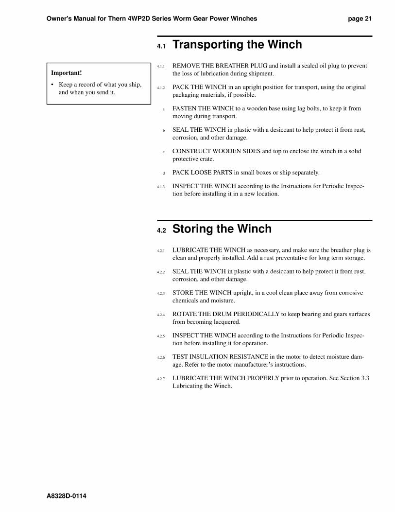
4.1 Transporting the Winch
4.1.1 REMOVE THE BREATHER PLUG and install a sealed oil plug to prevent
the loss of lu bri ca tion during shipment.
4.1.2 PACK THE WINCH in an upright position for transport, using the original
packaging materials, if possible.
a FASTEN THE WINCH to a wooden base using lag bolts, to keep it from
mov ing during transport.
b SEAL THE WINCH in plastic with a desiccant to help protect it from rust,
corrosion, and other damage.
c CONSTRUCT WOODEN SIDES and top to enclose the winch in a solid
pro tec tive crate.
d PACK LOOSE PARTS in small box es or ship separately.
4.1.3 INSPECT THE WINCH according to the Instructions for Periodic In spec -
tion before installing it in a new location.
4.2 Storing the Winch
4.2.1 LUBRICATE THE WINCH as necessary, and make sure the breather plug is
clean and properly installed. Add a rust preventative for long term storage.
4.2.2 SEAL THE WINCH in plastic with a desiccant to help protect it from rust,
corrosion, and other damage.
4.2.3 STORE THE WINCH upright, in a cool clean place away from corrosive
chem i cals and moisture.
4.2.4 ROTATE THE DRUM PERIODICALLY to keep bearing and gears sur fac es
from becoming lacquered.
4.2.5 INSPECT THE WINCH according to the Instructions for Periodic In spec -
tion before installing it for operation.
4.2.6 TEST INSULATION RESISTANCE in the motor to detect mois ture dam-
age. Refer to the motor manufacturer’s in struc tions.
4.2.7 LUBRICATE THE WINCH PROPERLY prior to operation. See Section 3.3
Lubricating the Winch.
Important!
• Keep a record of what you ship,
and when you send it.
Owner's Manual for Thern 4WP2D Series Worm Gear Power Winchespage 22
A8328D-0114
12
43
11
6
98765
10
14
15
12
20
21 13
16 17 18 19
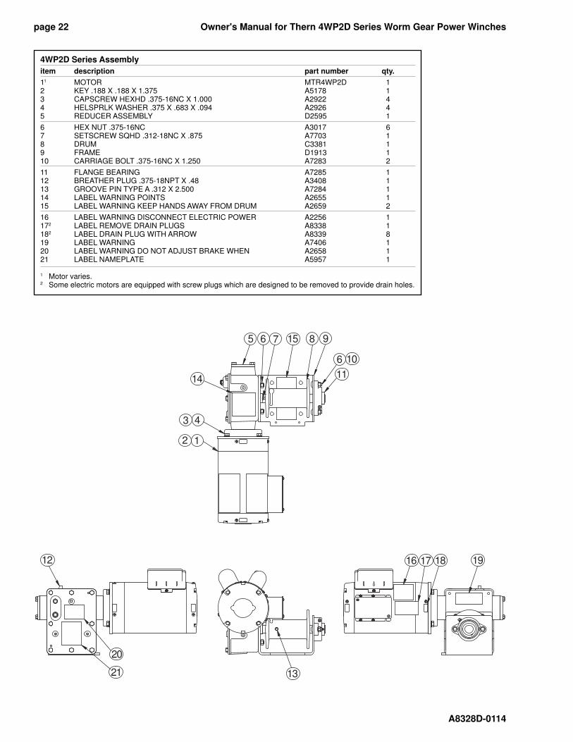
4WP2D Series Assembly
item description part number qty.
11 MOTOR MTR4WP2D 12 KEY .188 X .188 X 1.375 A5178 13 CAPSCREW HEXHD .375-16NC X 1.000 A2922 44 HELSPRLK WASHER .375 X .683 X .094 A2926 45 REDUCER ASSEMBLY D2595 1
6 HEX NUT .375-16NC A3017 67 SETSCREW SQHD .312-18NC X .875 A7703 18 DRUM C3381 19 FRAME D1913 110 CARRIAGE BOLT .375-16NC X 1.250 A7283 2
11 FLANGE BEARING A7285 112 BREATHER PLUG .375-18NPT X .48 A3408 113 GROOVE PIN TYPE A .312 X 2.500 A7284 114 LABEL WARNING POINTS A2655 115 LABEL WARNING KEEP HANDS AWAY FROM DRUM A2659 2
16 LABEL WARNING DISCONNECT ELECTRIC POWER A2256 1172 LABEL REMOVE DRAIN PLUGS A8338 1182 LABEL DRAIN PLUG WITH ARROW A8339 819 LABEL WARNING A7406 120 LABEL WARNING DO NOT ADJUST BRAKE WHEN A2658 121 LABEL NAMEPLATE A5957 1
1 Motor varies. 2 Some electric motors are equipped with screw plugs which are designed to be removed to provide drain holes.
Owner's Manual for Thern 4WP2D Series Worm Gear Power Winches page 23
A8328D-0114
12
6
21
19
43
98765
18
10
2425 17
19 11 20 21 22 23 13
14
15
16
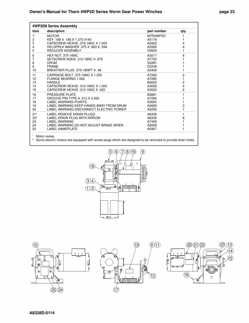
4WP2D8 Series Assembly
item description part number qty.
11 MOTOR MTR4WP2D 12 KEY .188 X .188 X 1.375 4140 A5178 13 CAPSCREW HEXHD .375-16NC X 1.000 A2922 44 HELSPRLK WASHER .375 X .683 X .094 A2926 45 REDUCER ASSEMBLY D2600 1
6 HEX NUT .375-16NC A3017 67 SETSCREW SQHD .312-18NC X .875 A7703 18 DRUM D2281 19 FRAME D2248 110 BREATHER PLUG .375-18NPT X .48 A3408 1
11 CARRIAGE BOLT .375-16NC X 1.250 A7283 212 FLANGE BEARING 1.062 A7285 113 HANDLE B3620 214 CAPSCREW HEXHD .312-18NC X 1.000 A3028 415 CAPSCREW HEXHD .312-18NC X .625 A3529 2
16 PRESSURE PLATE B3861 117 GROOVE PIN TYPE A .312 X 2.500 A7284 118 LABEL WARNING POINTS A2655 119 LABEL WARNING KEEP HANDS AWAY FROM DRUM A2659 220 LABEL WARNING DISCONNECT ELECTRIC POWER A2256 1
212 LABEL REMOVE DRAIN PLUGS A8338 1222 LABEL DRAIN PLUG WITH ARROW A8339 823 LABEL WARNING A7406 124 LABEL WARNING DO NOT ADJUST BRAKE WHEN A2658 125 LABEL NAMEPLATE A5957 1
1 Motor varies. 2 Some electric motors are equipped with screw plugs which are designed to be removed to provide drain holes.
Owner's Manual for Thern 4WP2D Series Worm Gear Power Winchespage 24
A8328D-0114
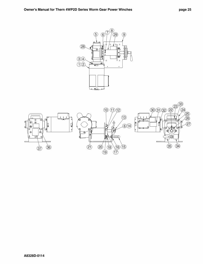
4WP2DC Series Assembly
item description part number qty.11 MOTOR MTR4WP2D 12 KEY .188 X .188 X 1.375 A5178 13 CAPSCREW HEXHD .375-16NC X 1.000 A2922 44 HELSPRLK WASHER .375 X .683 X .094 A2926 45 REDUCER ASSEMBLY D2601 1
6 HEX NUT .375-16NC A3017 67 SETSCREW SOKHD .312-18NC X .375 A3745 18 DRUM D2337 19 FRAME D2248 110 ZERK DRIVE .250 A3988 1
11 TOP CLUTCH C3695 112 CAPSCREW SOKHD .375-16NC X 1.000 A3445 213 BEARING FLANGE 1.062 A7285 114 CARRIAGE BOLT .375-16NC X 1.250 A7283 215 PUSH PULL CLAMP A7785 1
16 FLAT WASHER SAE .750 X 1.469 X .134 A6500 117 SPRING PLUNGER NYLK .375-16NC X 1.125 A7792 218 BOTTOM CLUTCH C3697 119 HELSPRLK WASHER .312 X .586 X .078 A2925 120 CAPSCREW SOKHD .312-18NC X 1.250 A3548 1
21 GROOVE PIN TYPE A .312 X 2.500 A7284 122 CAPSCREW SOKFLTHD 10-24NC X 1.250 A7794 423 BREATHER PLUG .375-18NPT X .48 A3408 124 HANDLE B3620 225 CAPSCREW HEXHD .312-18NC X 1.000 A3028 2
26 CLUTCH HUB B3927 127 CAPSCREW HEXHD .312-18NC X .625 A3529 228 LABEL WARNING POINTS A2655 129 LABEL WARNING KEEP HANDS AWAY FROM DRUM A2659 230 LABEL WARNING DISCONNECT ELECTRIC POWER A2256 1
312 LABEL REMOVE DRAIN PLUGS A8338 1322 LABEL DRAIN PLUG WITH ARROW A8339 833 LABEL WARNING A7406 134 LABEL CLUTCH DISENGAGED A7842 135 LABEL CLUTCH ENGAGE A7843 1
36 LABEL WARNING DO NOT ADJUST BRAKE WHEN A2658 137 LABEL NAMEPLATE A5957 1
1 Motor varies. 2 Some electric motors are equipped with screw plugs which are designed to be removed to provide drain holes.
Owner's Manual for Thern 4WP2D Series Worm Gear Power Winches page 25
A8328D-0114
37 36
76
21
29
28
43
98
5
2230 31 3223
33
2425
26
27
35 34
6
21 20
19
18
17
16 15
10 11 12
14
13
Owner's Manual for Thern 4WP2D Series Worm Gear Power Winchespage 26
A8328D-0114
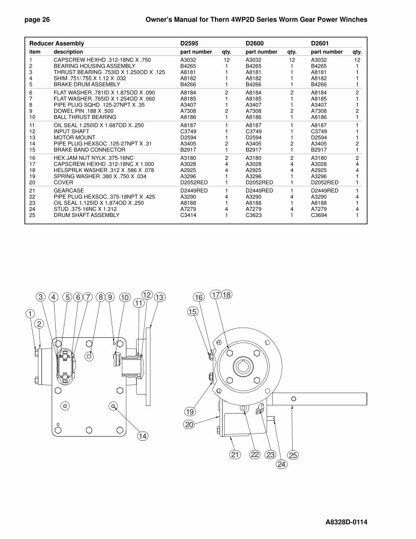
Reducer Assembly D2595 D2600 D2601
item description part number qty. part number qty. part number qty.
1 CAPSCREW HEXHD .312-18NC X .750 A3032 12 A3032 12 A3032 122 BEARING HOUSING ASSEMBLY B4265 1 B4265 1 B4265 13 THRUST BEARING .753ID X 1.250OD X .125 A8181 1 A8181 1 A8181 14 SHIM .751/.755 X 1.12 X .032 A8182 1 A8182 1 A8182 15 BRAKE DRUM ASSEMBLY B4266 1 B4266 1 B4266 1
6 FLAT WASHER .781ID X 1.875OD X .090 A8184 2 A8184 2 A8184 27 FLAT WASHER .765ID X 1.254OD X .060 A8185 1 A8185 1 A8185 18 PIPE PLUG SQHD .125-27NPT X .35 A3407 1 A3407 1 A3407 19 DOWEL PIN .188 X .500 A7308 2 A7308 2 A7308 210 BALL THRUST BEARING A8186 1 A8186 1 A8186 1
11 OIL SEAL 1.250ID X 1.687OD X .250 A8187 1 A8187 1 A8187 112 INPUT SHAFT C3749 1 C3749 1 C3749 113 MOTOR MOUNT D2594 1 D2594 1 D2594 114 PIPE PLUG HEXSOC .125-27NPT X .31 A3405 2 A3405 2 A3405 215 BRAKE BAND CONNECTOR B2917 1 B2917 1 B2917 1
16 HEX JAM NUT NYLK .375-16NC A3180 2 A3180 2 A3180 217 CAPSCREW HEXHD .312-18NC X 1.000 A3028 4 A3028 4 A3028 418 HELSPRLK WASHER .312 X .586 X .078 A2925 4 A2925 4 A2925 419 SPRING WASHER .380 X .750 X .034 A3296 1 A3296 1 A3296 120 COVER D2052RED 1 D2052RED 1 D2052RED 1
21 GEARCASE D2449RED 1 D2449RED 1 D2449RED 122 PIPE PLUG HEXSOC .375-18NPT X .425 A3290 4 A3290 4 A3290 423 OIL SEAL 1.125ID X 1.874OD X .250 A8188 1 A8188 1 A8188 124 STUD .375-16NC X 1.312 A7279 4 A7279 4 A7279 425 DRUM SHAFT ASSEMBLY C3414 1 C3623 1 C3694 1
3
2
4 65 7 98 1011
13
1
12
15
16 1817
19
20
21 22 23
2425
14
Owner's Manual for Thern 4WP2D Series Worm Gear Power Winches page 27
A8328D-0114
1
2
34 5 6 87
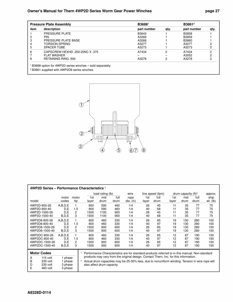
Pressure Plate Assembly B36881 B38612
item description part number qty. part number qty.
1 PRESSURE PLATE B3643 1 B3858 12 PIN A3269 1 B3859 13 PRESSURE PLATE BASE A3268 1 B3860 14 TORSION SPRING A3277 1 A3277 25 SPACER TUBE A3273 1 A3273 2
6 CAPSCREW HEXHD .250-20NC X .375 A7434 2 A7434 27 FLAT WASHER – – A3052 28 RETAINING RING .500 A3278 2 A3278 2
1 B3688 option for 4WP2D series winches – sold separately.2 B3861 supplied with 4WP2D8 series winches.
4WP2D Series – Performance Characteristics 1
load rating (lb) wire line speed (fpm) drum capacity (ft)2 approx.
motor motor 1st mid full rope 1st full 1st mid full shipmodel codes hp layer drum drum dia. (in) layer drum layer drum drum wt. (lb)
4WP2D-800-26 A,B,D,E 1 800 590 460 1/4 26 45 11 35 77 754WP2D-800-40 D,E 1.5 800 590 460 1/4 40 68 11 35 77 754WP2D-1500-26 D,E 2 1500 1100 900 1/4 26 45 11 35 77 754WP2D-1500-40 B,D,E 3 1500 1100 900 1/4 40 68 11 35 77 75
4WP2D8-800-26 A,B,D,E 1 800 460 330 1/4 26 65 19 130 280 1004WP2D8-800-40 D,E 1.5 800 460 330 1/4 40 97 19 130 280 1004WP2D8-1500-26 D,E 2 1500 900 600 1/4 26 65 19 130 280 1004WP2D8-1500-40 B,D,E 3 1500 900 600 1/4 40 97 19 130 280 100
4WP2DC-800-26 A,B,D,E 1 800 460 330 1/4 26 65 12 87 190 100 4WP2DC-800-40 D,E 1.5 800 460 330 1/4 40 97 12 87 190 1004WP2DC-1500-26 D,E 2 1500 900 600 1/4 26 65 12 87 190 1004WP2DC-1500-40 B,D,E 3 1500 900 600 1/4 40 97 12 87 190 100
Motor Codes
A 115 volt 1 phaseB 230 volt 1 phaseD 230 volt 3 phaseE 460 volt 3 phase
1 Performance Characteristics are for standard products referred to in this manual. Non-standard products may vary from the original design. Contact Thern, Inc. for this information. 2 Actual drum capacities may be 25-30% less, due to nonuniform winding. Tension in wire rope will also affect drum capacity.

Thern, Incorporated5712 Industrial Park RoadWinona, MN 55987
PHN 507-454-2996FAX 507-454-5282
EMAIL: [email protected]