Embed Size (px)
Citation preview

Graphic and Digital Displays!The Ultimate battery monitor for...
...Marine Systems...Alternative Energy Systems
...Recreational Vehicle Systems...Industrial Lift Truck Applications
...Electric Vehicles and many more!The world's most accuratestate-of-charge monitor!
Copyright 1995-1998 Manual Part # 890015 Rev.5D 1/15/98
Owner's Manual
EINSTAL5D.PM6
Patented

2
Help Index
Advanced Functions, 30-38
Battery Basics, 8
CE Declaration of Conformity, 51Charge Efficiency Factor, 23
Charged Parameters, 22-23
High Voltage Notes, 50
Historical Data, 29
Installation (General), 9-15
Introduction, 7
Low Battery Alarm, 27, 35-38
Low Voltage, 27
Meter Wiring Detail, 14
Mounting, 10
Operation (Basic), 18-24
Options and Versions, 44
Peukert’s Equation, 26, 39-42
Prescaler (optional), 45
Quick Reference Guide, 5-6
Reading the Bar Graph, 19
Removing, 11
Reset and Lock, 28
Serial Port, RS-232(optional), 49
Setting Battery Capacity, 21
Setting Peukert's Exponent, 26
Setting Up t , 24
Shunt & Battery Wires, 13
Specifications, 3
Start Up, 16
Synchronizing Your Meter, 17
Temp. Sensor (optional), 25
Troubleshooting, 43
Using the Buttons, 20
Warranty Support, 52
Wire by Wire Check, 15
Wiring Overview, 12
DO NOT INSTALL OR USE THIS PRODUCT UNTIL YOU HAVE READTHE ENTIRE OWNER’S MANUAL. IMPROPER INSTALLATION OFTHIS UNIT MAY BE HAZARDOUS AND VOIDS YOUR WARRANTY.

3
SpecificationsVoltage: For 12V - 24V systems. Optional Prescalers extend voltage range.
Standard Model: Two Auto-ranges: 0 to 19.95V (0.05V resolution)20.0 to 50.0V (0.1V resolution)
Optional Prescalers: 0-100V, 0-500V (Used with standard model)Amperage:
Low Range: + 0 - 40.0 Amps (0.1 Amp resolution)High Range: + 500 Amps (1 Amp resolution)
Amp-hours:Low Range: +0 - 199.9 Amp-hours (0.1 Amp-hour resolution)High Range: + 200 - 1999 Amp-hours (1 Amp-hour resolution)
Time Remaining:Low Range: 0 to 199.9 Hours (0.1 hour resolution)High Range: 0 to 255 Hours (1.0 hour resolution)
Power Requirements:9.5-40 Volts DCCurrent: 50-150 mA (Depends on Ambient light. Display Auto Dims.)
28 mA (Sleep Mode - Bar Graph Display Only)Shunt type required: 50 mV @ 500 AmpAccuracy:
Voltage: + (0.6% of reading + 1 least count of resolution)Amperage: + (0.8% of reading + 1 least count of resolution)Amp-hours: Ahr Error ~ (Time of measurement x current error)
Physical:Max. Outer Bezel Diameter: 2.5 inches (63.5mm)Max. Barrel diameter: 1.95" (50mm)Max. Depth: (from back of bezel) 3.15 inches (80mm)Hole Cutout Size: Use 2" or 2 1/16" hole saw (52mm)Water Resistance: Splashproof front panel.Weight: 8 Ounces (227g)
V
t
A
Ah

4
Top Rear View of Meter-DC Meter Negative (BLACK) [1]
Shunt Sense Lead Load Side (GREEN) [2]Shunt Sense Lead Battery Side (ORANGE) [3]
Battery Volt Sense (0-50V DC1) (BLUE) [4]+DC Meter Power (9.5-40V DC) (RED) [5]
Optional Temperature Sensor Input [6] Optional Low Battery Alarm [7]
Optional Temperature Sensor Ground [8]
SYSTEM POSITIVE
SYSTEM NEGATIVE
12345671234567123456712345671234567
Twisted pair wire is used for shuntsensing leads for noise immunity.
Battery Compartment
+-
2 AmpFuses
Your Meter workswith flooded or gellead-acid batteries
Basic Wiring Diagram
The 500 A 50mVshunt senses cur-rent in or out ofyour battery.
Meter Location
+-

5
Quick Reference
Full
80-99% +
60-79%+
40-59%+
20-39%+
0-19%+
EMPTY FULL
The Light BarThe light bar shows state-of-charge at a glance.
Here's what the lights mean:
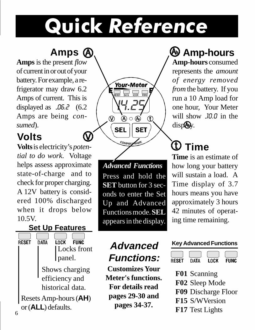
When you press the button, youSELect a numeric display. In normaloperation, each press illuminates a sta-tus light. The light indicates Voltsare being displayed, the light indi-cates Amps, indicates Amp-hours,and indicates Time. We’ll explainthese terms on the next page.
The Button
For shortest charging times,lead acid battery in marine orRV service is normally dis-charged 50% then rechargedto 85-90% of full. Restoringthe last 10-15% of a full chargerequires a long time - typically2 - 3 hours. This means only35-40% of your battery capac-ity is actually available fornormal use. Occasionally dis-charging a battery more deeplyis perfectly acceptable.
Status LightsShows what number isbeing displayed
6
Volts is electricity’s poten-tial to do work. Voltagehelps assess approximatestate-of-charge and tocheck for proper charging.A 12V battery is consid-ered 100% dischargedwhen it drops below10.5V.
Amps is the present flowof current in or out of yourbattery. For example, a re-frigerator may draw 6.2Amps of current. This isdisplayed as -06.2 (6.2Amps are being con-sumed).
Time is an estimate ofhow long your batterywill sustain a load. ATime display of 3.7hours means you haveapproximately 3 hours42 minutes of operat-ing time remaining.
Amp-hours consumedrepresents the amountof energy removedfrom the battery. If yourun a 10 Amp load forone hour, Your Meterwill show -10.0 in thedisplay.
Volts
Amps
Time
Amp-hours
Press and hold theSET button for 3 sec-onds to enter the SetUp and AdvancedFunctions mode. SELappears in the display.
Advanced Functions
Key Advanced Functions
Set Up Features
AdvancedFunctions:Customizes YourMeter's functions.For details readpages 29-30 and
pages 34-37.
Locks frontpanel.
Shows chargingefficiency andhistorical data.
Resets Amp-hours (AH)or (ALL ) defaults.
F01 ScanningF02 Sleep ModeF09 Discharge FloorF15 S/WVersionF17 Test Lights
Quick Reference
7
IntroductionCongratulations! Your Meter is the most advanced (Patents Pending) DCpower measurement instrument available. It shows you:
Battery State-of-Charge on a multicolor light bar.
System voltage accurate to 1/20th of a Volt (<20VDC).
System current accurate to 1/10th of an Amp (<40 Amps).
Amp-hours removed from, or put into, your battery.
Time of operation remaining until recharging is required.
This meter is sold under a variety of brand names: Cruising EquipmentCompany meters are called an E-Meter . Heart Interface units are la-beled Link 10 . Other companies have private brand names for this prod-uct. For convenience, this manual refers to all units as "Your Meter "since all meters support identical functions.
For installation and operation questions, please contact the company whosename appears on the face of Your Meter . For warranty and technicalsupport please follow the process outlined on Page 51.
If you wish Your Meter to support an external Low Battery Alarm, such asa bell or buzzer, or if you need Your Meter to report data to a computer ordata logging unit, these options must be included at the time of manufac-ture and can not be retrofitted in the field.
The installation of Your Meter is simple, as is its operation. However,there many advanced features and functions, so please take the time toread and thorough understand this manual.
Installers Note: This manual contains operatinginstructions. Please leave it with the meter!

8
Why monitor a battery?
Batteries can be ruined by excessive discharge. They may also be dam-aged by under-charging. A battery (or bank of batteries) may be storingless energy than you think. Your Meter provides all the key data you, oryour technician, need to make decisions about battery use and charging.
How does Your Meter work?Your Meter uses sophisticated microprocessor technology to report allsignificant battery information. Your Meter monitors battery voltage andcurrent over time to report Amp-hours consumed and time remaining --precisely the information necessary to maximize system performance.
What's an Amp-hour?Batteries are rated by Amp-hour capacity. A battery which delivers oneAmp for one hour has delivered one Amp-hour. Marine and RV deepcycle battery capacity is based on their 20 hour discharge rate. A batterywhich delivers 10 Amps to a load for 20 hours before battery voltagedrops to 10.5 Volts, is considered a "200 Amp-hour" battery. 10 Ampstimes 20 hours equals 200 Amp-hours.
For maximum life you should never discharge more than half the ratedcapacity of a battery. Therefore, if you have a 200 Amp-hour battery, youshould recharge when Your Meter shows -100 in the Amp-hour display.The -100 means 100 Amp-hours have been removed from your battery.
FOR MAXIMUM BATTERY LIFE, RECHARGEYOUR BATTERIES WHEN YOU HAVE DIS-
CHARGED 50% OF THEIR AMP-HOUR CAPACITY.
Battery Basics

9
Basic installation of Your Meter on a 12 or 24 Volt system involves only 5wires. Because Your Meter will work on systems up to 500 Volts, specialhigh voltage installation techniques are discussed beginning on Page 44.You need to read this section if you're working on an electric vehicle orsystem where more than 50 Volts is encountered. If your installation ison a 12 or 24 Volt system, let's get to work!
Installation PlanningFirst, gather all the tools you'll need for installation. We recommend:
* A 2" or 2 1/16" (52mm) hole saw to make the panel cutout.* A 3/8" drill with bits to run power and shunt wiring.* An adjustable 9/16" wrench for shunt bolt connections.* Wire stripper/crimper and a small flat blade screwdriver.
Make sure you have all the parts you'll need to complete the job:
* A 500A - 50 mV shunt (May be supplied with Your Meter)* #18 or #16 twisted pair shunt wire long enough to reach
from the battery to the meter location. Ask your dealer forCruising Equipment PN 910009 - 25' 4 twisted pair cableor PN 910010 - 50' 4 twisted pair cable (not included).
* 2 in-line fuse holders with 2 Amp fuses.
CAUTION: DO NOT INSTALL FUSES UNTIL YOU COMPLETE INSTRUCTIONS ON PAGE 10-15.
* A short heavy duty battery cable to run from one shunt boltto the battery. Cable is available at auto and marine shops.
* Assorted small gauge crimp type terminals for connectinging the power, shunt, fuses, and voltage sense leads.
Installation

10
Mounting
Our Patent Pending "Ratchet Ring" makes mounting easy and fast .
TIP: When installing from the front of apanel or dashboard slide the Ratchet Ringonto cable with correct orientationand then connnectthe wires.
123451234512345123451234512345123451234512345
Push Ratchet Ringon untill firmly in con-
tact with panel.
The gasket around the ringof Your Meter should pro-vide an adequate seal againstmoisture. If a sealant is usedbe sure it is silicone so thatthe meter may be removedwithout damage.
CAUTION!Orient ring so the ratchetteeth will engage properly.Practice installing and re-moving ring before finalassembly. Considerableforce is required, this en-sures the ring will notloosen over time.
Install the meter from the front of yourpanel. The panel thickness may be from1/16" to 1 1/2". Slip the locking ring onfrom the rear and press forward until it'steeth hold the meter securely in place.
PATENTED

11
Removing
Removing Your Meter is the reverse of mounting witha TWIST as shown in the following diagrams.
Twist 1/8th turn tounlock teeth.
Then pull lock ringstraight back as shownbelow.
Pull bothsides ofthe lockring equally
Patented
PATENT PENDING

12
Wiring OverviewThis drawing is for 12V & 24V systems.For higher voltages see Prescaler use on Page 44.
DC+
Twisted pair cable
Fuses
Terminal StripConnections
See Detail Page 14
Mounting Page 10Removing Page 11
INSTALLATION TIP:Use appropriate strain relief toavoid damage to the connectorand terminal strip on the rear ofYour Meter.
DC-(system ground)See Detail Page 13
Shunt
+
-
NOTE: To limit Voltage measurement error do not exceede wire lengthsshown below. Error assumes 16 AWG wire and max. power consumption.
0.5% Error 72 Feet Maximum1.0% Error 150 Feet Maximum3.0% Error 450 Feet Maximum
TIP: For a neat and professional looking installation use plenty of:* Nylon wire wraps* Wire wrap anchor points.

13
Shunt & Battery WiresThe shunt is the current sensor for Your Meter. Its 500A 50mV ratingmeans that when 500 Amps flows through it there is 50mV generatedacross it. The millivolt signal is translated into an Amps display in themeter. For example: A 50A load would generate 5mV across the shuntand would be displayed as 50 Amps. Caution: In the diagram below, thedarker wires represent primary wiring and should be able to carry fullbattery load current. Size appropriately!
12345678901234567890123456789012123123456789012345678901234567890121231234567890123456789012345678901212312345678901234567890123456789012123123456789012345678901234567890121231234567890123456789012345678901212312345678901234567890123456789012123123456789012345678901234567890121231234567890123456789012345678901212312345678901234567890123456789012123123456789012345678901234567890121231234567890123456789012345678901212312345678901234567890123456789012123123456789012345678901234567890121231234567890123456789012345678901212312345678901234567890123456789012123123456789012345678901234567890121231234567890123456789012345678901212312345678901234567890123456789012123123456789012345678901234567890121231234567890123456789012345678901212312345678901234567890123456789012123123456789012345678901234567890121231234567890123456789012345678901212312345678901234567890123456789012123
123456781234567812345678
123123123123
123456789123456789123456789123456789
123456781234567812345678
123123123123
123456789123456789123456789123456789
123451234512345123451234512345
1234512345123451234512345
RED
BLUE
+-
ORANGE
GREEN
These wiresmust be a
twisted pair!!
4 Twisted paircable. See Page 16for part numbers.
2 Amp Fuses(mount within 7"of battery)
BLACK
SYSTEM POSITIVE
Connect NOother wires di-rectly to batterynegative! Allcurr ent mustflow thr ough theshunt!
BATTERYSIDE
LOADSIDE
500A 50 mVSHUNT
SYSTEM NEGATIVE
LOAD SIDE
14
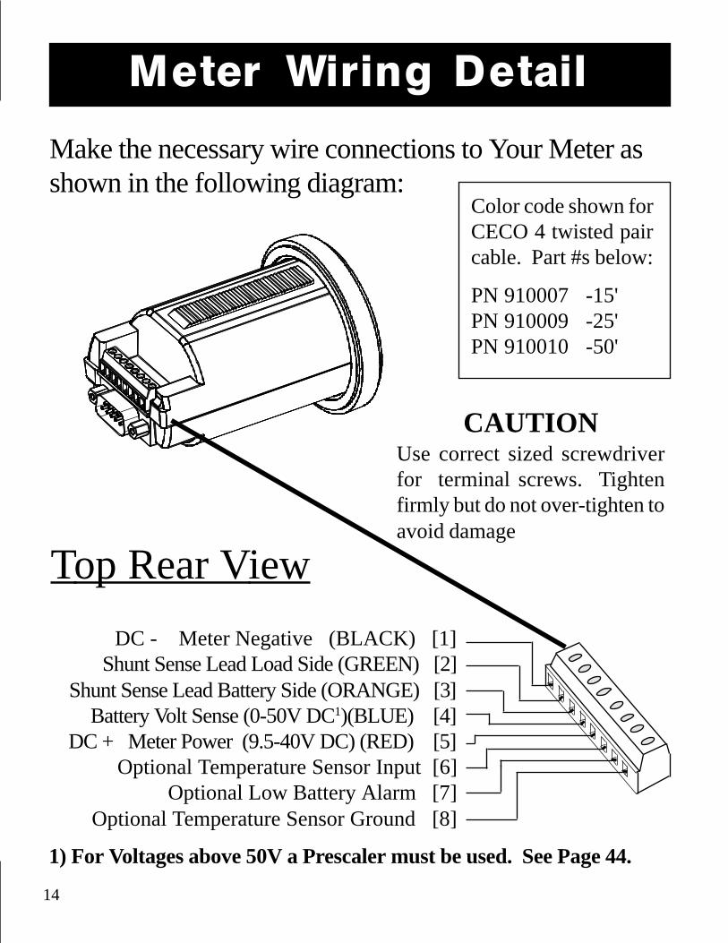
Meter Wiring Detail
Make the necessary wire connections to Your Meter asshown in the following diagram:
CAUTIONUse correct sized screwdriverfor terminal screws. Tightenfirmly but do not over-tighten toavoid damage
Color code shown forCECO 4 twisted paircable. Part #s below:
PN 910007 -15'PN 910009 -25'PN 910010 -50'
1) For Voltages above 50V a Prescaler must be used. See Page 44.
DC - Meter Negative (BLACK) [1]Shunt Sense Lead Load Side (GREEN) [2]
Shunt Sense Lead Battery Side (ORANGE) [3]Battery Volt Sense (0-50V DC1)(BLUE) [4]
DC + Meter Power (9.5-40V DC) (RED) [5]Optional Temperature Sensor Input [6]
Optional Low Battery Alarm [7]Optional Temperature Sensor Ground [8]
Top Rear View

15
Most failures and problems are due to wiring errors. Please double check thewiring. (Color code shown is for CECO wire Part #s on Page 14.)
#1 - DC Power (Black Wire). Start at terminal #1 of the meter and follow itto the big bolt on the Load side of the shunt. Do not connect this wire tothe small screw terminal with the Green shunt sense lead.
#2 Shunt Sense Lead Load Side (Green Wire). This wire connects to thesmall screw on the Load side of the shunt. This wire must be a twistedpair with the Orange wire described below. To check this wire start atterminal #2 and follow it to the small screw on the Load side of the shunt.There should be no other wires connected to this screw.NOTE: Also check the primary wiring from the shunt to the battery.There should be only one heavy cable from the Battery side of the shunt tothe battery. All loads and sources must be connected on the other side ofthe shunt. Only the shunt may be connected directly to battery negative!
#3 Battery Side of Shunt (Orange Wire). This wire must be a twistedpair with the Green wire described above. To check this wire start at ter-minal #3 and follow it to the small screw on the Battery side of the shunt.There should be no other wires connected to this screw.
#4 Voltage Sense Wire (Bat.+) (Blue Wire). From terminal #4 this wireshould run to a 2 amp fuse holder, located within 7" of the battery. Theother side of the fuse holder should go to the positive (+) battery post.If Voltage is greater than 50V, see High Voltage Prescaler, Page 44.
#5 + DC Power (Red Wire). This wire should run from terminal #5 to a 2Amp fuse holder located within 7" of the battery. The fuse should not yetbe installed. The other side of the fuse holder goes to the battery. If powersupply Voltage is above 24V, see the Electric Vehicles section, Page 45.
Wire by Wire Check

16
Once you have completed ALL instructions on Page 17, insert the voltage sensewire fuse, then the meter power fuse. (BLUE wire fuse first, RED wire fuselast!) The fuse should be in a fuse holder and should be connected in a smoothmotion. A "ragged" power up may cause a meter lock up. Both the bar graphand digital display should come on.
Factory Default Settings
Your Meter comes on in the (Volts) mode with the display flashing toindicate that it has been powered up from the de-powered state. (see page 26)Left untouched for 10 minutes, Your Meter will go to "sleep", turning off thedigital display leaving only the bar graph on. (This is a power saving feature.)Touching either the SEL or SET buttons will return Your Meter to the functionYour Meter was in when it went to "sleep".
Your Meter is designed to work "out of the box". The factory default values areappropriate for a moderate capacity 12V liquid lead acid battery and a typicaluser display and function setup. Often the only change that must be made issetting the battery capacity. You may also have to set the appropriate Peukert'sexponent for your battery ( See page 24). Special functions and display optionsare described beginning on Page 27.
Your Meter's factory default settings are:1. Automatic Scanning of V, A, Ahrs, and time will be OFF.2. Sleep Mode is ON. Turns digital display off after 10 min.3. Charge Efficiency Factor (CEF) equals 90% and learn CEF mode is on.4. Charged Parameters: Voltage =13.2, Charged Current =2%. The bat-
tery must exceed 13.2V and the current must be less, in Amps, than 2% ofdeclared capacity for 5 minutes for Your Meter to consider the battery full.
5. Battery capacity set to 200 Amp-hours.6. Peukert Exponent = 1.25.
Start Up

17
Synchronizing Your MeterSynchronize Your Meter to a full battery.After installing Your Meter, charge the battery until the far right GreenLED begins flashing, which indicates the Charged Parameters have beenmet. Amp-hours will have started at 0 and counted up as a positive num-ber. As you begin discharging the battery, the LED will stop flashing andthe numeric Amp-hour display resets to 0. Your Meter is shipped fromthe factory assuming a 200 Amp-hour battery. Your battery may be adifferent size. To change battery size, see Page 21.
Staying in Sync, Removing Accumulated Negative Ahrs.Should Your Meter ever become out of sync with the battery state-of-charge simply charge until the far right LED flashes Green. You may alsoget back in sync by charging until the battery is full and then resetting theAmp-hours to zero through the RESET function.
If Your Meter should accumulate a negative number in the Amp-hourdisplay you will have to charge until you meet the conditions for a recal-culation of the Charging Efficiency (CEF) as described on Pages 22 & 23.If you do not meet all five of the conditions listed below you will not geta recalculation of the CEF and a reset to Zero Ahrs consumed.
CONDITIONS TO RESET TO ZERO1) Discharge 10% of declared battery capacity to trigger algorithim2) Recharge until 100% of the Kwhrs removed have been returned.3) The Voltage must be above the Charged Voltage Parameter.4) The current must be below the Charge Current Parameter.5) Conditions 3 & 4 must be met for 5 minutes (1 min. for AE default)

18
Although Your Meter is a very sophisticated device, obtaining basic batteryinformation from it is simple. With the unit turned on and the (Volts) LEDon, let's learn how to display the four most important DC system parameters .
When you touch the button, youare SELecting the display you wish.Each time you touch SEL in normaloperation, you will toggle to the nextitem to the right (Volts) goes to (Amps) to (Amp-hours) to (time).
Now press SEL to bring up these functions.
Operation
Volts is the electric potential to do work. Voltage is useful to assess theapproximate state-of-charge and to check for proper charging. Examples:An at rest, fully charged battery will show about 12.8V. A 12 V batteryis 100% discharged when it reachs 10.5Volts with a 20 hr. rated loadapplied. A typical charging voltage would be 14.2V.
Amps is the present flow of current in or out of the battery. For example,a refrigerator may draw 6 Amps of current. This is displayed as - 6.0 (6amps are being consumed). Discharge is shown as a negative numberand charging is shown as a positive number (unsigned).
Amp-hours consumed represents the amount of energy removed fromthe battery. If you run a 10 Amp load for one hour then ten Amp-hoursare consumed. Your Meter will show -I0 in the display. DuringchargingYour Meter will compensate for charging efficiency and countback up toward 0.
Time is an estimate of how long (in hours) the battery will sustain a load.It is based on a selectable, time averaged, rate of discharge. Default is theaverage of the last four minutes of use. (See Page 23)

19
Reading the Bar Graph
Under the LED bar graph are the words RESET, DATA, LOCK, andFUNC. These words are ignored during normal operation. They areused to indicate programming and advanced function modes which areexplained beginning on Page 34.
Setting Battery Capacity is ImportantThe LED bar graph display shows how much of your battery has been con-sumed. If you do not set your battery capacity correctly, your bar graph will notgive you an accurate indication of battery state-of-charge. Your Meter also usesdeclared capacity to calculate the Time Remaining, the charged current for ChargeEfficiency Factor calculations, and other control functions.
Setting capacity correctly is very important, see Page 21
BATTER Y STATE-OF-CHARGE
Full (Charged Parameters Met)
80-99% +
60-79%+
40-59%+
20-39%+
0-19%+
Above the digital display are four LEDs. They tell you the battery's state-of-charge at a glance. Four green LEDs means your battery is full. Oneflashing red light means it's nearly discharged. The table below shows thesix different displays indicating battery state-of-charge. Under certainlight conditions green may appear yellow.
EMPTY FULL

20
Pressing and holding the SET button for 3 seconds enters the Set Up andAdvanced Functions mode. The word SEL apppears in the display, prompting youto press the SEL button to choose what function you want to SELect.
Pressing SEL chooses a variable or function. The SET UP mode always beginsat the (Volts) function. Each press of the SEL button scrolls to the next item.When a variable or function is selected, its LED is on and its present value isdisplayed. To change an item press the SET button until the value appears thatyou wish. The order displayed and brief descriptions are below.
LIGHT DESCRIPTION
Charged Voltage ( The Voltage above which the battery must rise to be full.)
Charged Current % (Charging current must be below this percentage times
the battery capacity to be considered full. See Page 22-23.)
Battery Capacity in Amp-hours
Time interval over which current is averaged for time remaining function.
Using the Buttons
Advanced Functions. See Page 30.
Locks out SET button & Advanced Functions. SeePage 28.
Displays: CEF, # CEF Recalc's, Avg. Depth ofDischarge, Deepest Discharge, Avg. Rate of Dis-charge. See Page 29.
Resets Ahrs & allows Reset to Factory values. SeePage 28.
Each LED is lit in sequence to indicate function.

21
The first time you use Your Meter, it assumes you have 200 Amp-hour lead acidbatteries. If your battery capacity is different you must change the declaredbattery capacity. Follow these instructions to declare a new capacity:
1) Press and hold the SET button for 3 seconds to enter SET UP (and Ad-vanced Functions) menu. SEL appears in the display. Press SEL and notice thatthe green LED is on.
2) Press SEL again and note that the light comes on. Press again andnow the LED is on and 200 appears in the display. This is the defaultbattery capacity.
3) Now press and hold the SET button to scroll through battery size options.The display will show 1 Amp-hour increments from 20-40 Amp-hours of ca-pacity, 5 Amp-hour steps from 40-100 Amp-hours capacity and 20 Amp-hoursteps over 100 Amp-hours of capacity. If you continue to hold SET, after 4increments the display scrolls faster. When the value you want appears, releasethe SET button. If you overshoot your capacity you will have to scroll all theway to 1980 Ahrs after which the display will roll over and begin scrolling upstarting from 10 Amp-hours. NOTE: Versions of Your Meter prior to serialnumber 05000 increment only in 20 Amp-hour steps from 20 - 1980 Amp-hours .
4) After 10 seconds the meter exits the Set Up mode and the selected value isstored as the new battery capacity and the display returns to (Volts).
Tip: All SET UP and ADVANCED FUNCTIONS begin with the SET button.SET UP is normally done at installation. The SET button may be LOCKed toprevent unauthorized personnel from tampering with the SET functions. See"LOCK" on Page 32.
Setting Battery Capacity

22
The Charged ParametersYour Meter depends on the Charged Parameters to stay in sync with the batterystate-of-charge, to automatically reset to Zero, and to automatically calculate theCEF. The default settings are for 12V lead acid (liquid or gelled) batteries. Theyhave been carefully chosen to work on most systems, including constant voltageand multiple step charging systems.
The factory Charged Parameters are 13.2 Volts and 2% of battery capacity as acharged current. (2% of the default battery capacity of 200 Ahr equals 4 Amps).Several conditions must be met for a recalcualtion of the CEF and a reset to Zero:First 100% of the energy removed from the battery must be returned, additionallythe battery must be above 13.2 Volts and the current must fall below 4 Amps, forfive minutes, when all these conditions are met the battery is considered full.
CAUTION: If your battery voltage is other than 12V you MUST set up anappropriate Charged Voltage.
If the charged parameters are not set correctly,
Your Meter will never recalculate the CEF!
Please consider changing only the battery capacity unless your system falls intoone of the following categories:
1) Battery chemistry other than lead acid.12 Volt NiCad (and NiFe) systems would normally use 15.5 to 15.7 as theCharged Voltage. See your battery specifications for guidance. TheCharged Current % can probably stay at 2% of declared battery capacity.
2) Charging normally ends before current drops below 2%.If the charging system is normally shut down before charging current dropsbelow 2%, the Charged Current % will have to be changed.

23
Charged Parameters & CEFIf you change the Charged Parameters please use the following rules.
1) The Charged Voltage Parameter MUST BE AT LEAST 0.1V BE-LOW the voltage at which the charging system finishes charging.
Example: If your charging system finishes the battery at 13.8 Volts, aCharged Voltage Parameter of 14.0 Volts will not work. Lower the ChargedVoltage Parameter to 13.7 Volts or less.
2) The Charged Current % times declared Battery Capacity MUST beGREATER than the minimum current at which the charging systemmaintains the battery, or turns off.
If the Charged Current % times the Battery Capacity is less than the currentat which the charging system switches off, the Charged Current Parametercannot be met. For example, if the charging system shuts off when thecurrent is 10 Amps, using the factory default value of 4 Amps (2% of 200AHrs), will not work. Changing the Charged Current % to 6% would givea Charged Current of 12 Amps which would work.
WHY IS THE CEF IMPORTANT: The CEF determines the rate at which themeter counts back up during charging to compensate for the inefficiency of thecharging process. The CEF has a factory default value of 90% . This meansthat you must return 10.0 Ahrs to store 9.0 Ahr in the battery.
If you have a charging system that cannot satisfy the Charged Parameters, theCEF will not be recalculated and the meter will use the default CEF of 90%. Thiswill work fine in most systems. You may notice an accumulation of negativeAhrs. If so, set up appropriate Charged Parameters or resynchronizeperiodically.
24
Setting Up Five different displays are available in the Time function. You may select presentconsumption level, a four minute average, a sixteen minute, or a 32 minuteaverage, or display the percent of rate compensated capacity remaining. Whichmethod is best for you depends on your installation. Most installations will findfour minute averaging appropriate. To SET UP follow the procedure out-lined on Page 20. As you press the SET button the following values willappear, use the table below to choose the appropriate averaging period.
Instantaneous: Time Remaining Set Up Display: 0004 Minute Average: Time Remaining Set Up Display: 00I16 Minute Average: Time Remaining Set Up Display: 00232 Minute Average: Time Remaining Set Up Display: 003Percent Remaining: Time Remaining Set Up Display: 04P
Operating Tips: Use the longest period of time you can to insure long term loadvariations are considered. For instant feedback, use the 000 (no averaging)display. Time is in hours and 1/10th's of hours. In the Percent of CapacityRemaining mode, a full battery is displayed as 100P and counts down as yourdischarge. The Percent of Battery Capacity Remaining is referenced to theselected discharge floor and uses the instantaneous (not averaged) rate of dis-charge. The percent of capacity remaining display shows the percent numberwhich drives the Bar Graph. This function is very useful on Electric Vehicles.
CAUTION: Time displays are an estimate of how long your battery willsustain a load (to your selected discharge floor; default: 100% discharge). Varia-tions in discharge current, incorrectly set battery capacity, Peukert's exponent,temperature, and prior battery history may affect the accuracy of this estimate.Please use Time displays only as a guide. Use all displays (Volts, Amps, Amp-hours, and Time) to make informed decision about battery state-of-charge. Donot rely on a single value!
25
Your Meter may support an optional two wire temperature sensor. Thetemperature sensor is activated by turning Advanced Function F16 ON.
With F16 ON, F03 shows battery temperature in degrees Celcius. Whenactivated, F03 will continue to display temperature after exiting the SetUp mode until one of the two front panel buttons, SET or SEL is pressed.
The limits of the temperature sensor are 0 C (32F) to 99 C (210 F). Ver-sions of Your Meter prior to Serial Number 005000 do not support thisfunction.
Introduction to Peukert ExponentYour Meter shows true Amp-hours consumed in the Amp-hour display.However, the light bar shows how much of the available battery has beenconsumed. In 1897 a scientist named Peukert demonstrated that as youdischarge a battery more quickly, it's effective size temporarily decreases.A battery is considered fully discharged with it is no longer able to main-tain 10.5 Volts under load. As you'll see in the following table showingthe effect on a typical liquid cell battery, the faster the discharge rate, thesmaller its effective capacity:
Hours to Discharge Capacity as percent of 20 hr rating20 100%10 84% 5 67% 2 56% 1 47%
In other words, a 100 Amp-hour battery, discharged completely in one hourwill only supply 47 Amp-hours before dropping below 10.5V!
(optional) Temperature Sensor

26
Peukert's Exponent is a number which describes how battery capacity shrinksas the rate of discharge is increased. Your Meter uses a number between 1.00and 1.50 to describe how fast a particular battery will "shrink" when a heavyload is connected. A more complete technical discussion of the Peukert Expo-nent, and typical value tables is included on Pages 48-41.The key thing you need to know is that the Peukert Expopnent set at the factory,1.25, will be satisfactory for many liquid cell batteries. Gel cell batteries, orliquid cells with atypical plate structures, may require a different Peukert Expo-nent. To change the Peukert Exponent, proceed as follows:
1) Press and hold the SET button for 3 seconds to enter SET UP (and Ad-vanced Functions) menu. SEL appears in the display. Press SEL and notice thatthe green LED is on.
2) Press SEL again and note that the light comes on. Continue to pressthe SEL button until the letters F8 appear in the display. This will requireeighteen presses of the SEL button . The right most LED of the bar graph withthe legend FUNC under it will be lit.
3) Now press and hold the SET button. The default value of 1.25 (or thepreviously programed value) will appear in the display. The range of values isfrom 1.0 to 1.50. Holding down the SET button will cause the display toincrement in 0.01 steps, after 4 increments the display scrolls faster. When thevalue you want appears, release the SET button. If you overshoot your capacityyou will have to scroll all the way to 1.50 after which the display will roll overto 1.00 and continue incrementing. You also have to scroll all the way throughto declare exponents between 1.00 and 1.25.
4) After 10 seconds the meter exits the Set Up mode and the selected value isstored as the new Peukert's exponent and the display returns to (Volts).
Puekert Exponent

27
Alarms
Two Types of AlarmsYour Meter is equipped with both a visual Power Loss Alarm and a visualLow Battery Alarm. It is important that you understand the differencebetween these functions.
Power Loss Alarm: Shows when power being supplied to Your Meterhas dropped to an unsafe level. Certain display features are turned off asmeter power drops below internally set levels.
Low Battery Alarm: Shows when the battery being monitored has reachedeither a predetermined depth of discharge or has encountered at least 15seconds of continuous low voltage below a settable level. The Low Bat-tery Alarm is controlled by functions F10, F11 and F12 in the AdvancedFunctions Section.
Power Loss Alarm & Reset AnnunciationIf the Voltage supplying terminal #5 falls too low an automatic shut downoccurs. This voltage varies from a low of 7.2V to about 9.2 Volts depend-ing on how fast the voltage drops. When power is restored, the displaydefaults to the function and the digital display flashes. Pressing ei-ther the SEL or SET buttons cancels the flashing display. If the meter isin the sleep mode when power loss occurs, the display will flash for tenminutes and then go to sleep if no buttons are pressed. Once asleep thefirst button press will wake the display in the flashing mode to annunciatethe power loss. The second button press will cancel the flashing display.
28
In addition to reporting primary system values, Your Meter is capable of manyother front panel functions and will also display important historical batterydata. The words below the bar graph display indicate which of these functionsyou are accessing. To use these functions you must read and understand thefollowing section of this manual.
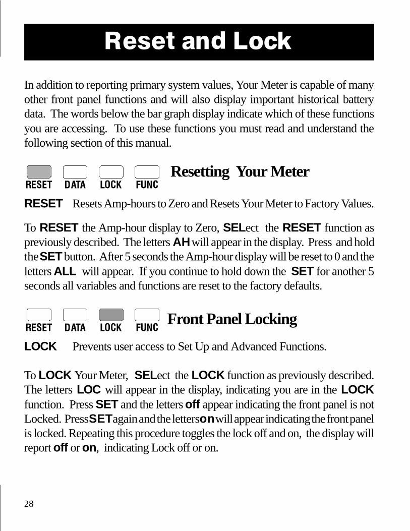
RESET DATA LOCK FUNC
Resetting Your Meter
RESET Resets Amp-hours to Zero and Resets Your Meter to Factory Values.
To RESET the Amp-hour display to Zero, SELect the RESET function aspreviously described. The letters AH will appear in the display. Press and holdthe SET button. After 5 seconds the Amp-hour display will be reset to 0 and theletters ALL will appear. If you continue to hold down the SET for another 5seconds all variables and functions are reset to the factory defaults.
RESET DATA LOCK FUNC Front Panel Locking
LOCK Prevents user access to Set Up and Advanced Functions.
To LOCK Your Meter, SELect the LOCK function as previously described.The letters LOC will appear in the display, indicating you are in the LOCKfunction. Press SET and the letters off appear indicating the front panel is notLocked. Press SET again and the letters on will appear indicating the front panelis locked. Repeating this procedure toggles the lock off and on, the display willreport off or on, indicating Lock off or on.
Reset and Lock

29
Historical Data
RESET DATA LOCK FUNC Key Battery Data Displayed
DATA Key historical battery information is available through this function. Eachtime the SEL button is pressed while in the DATA mode the next piece of datais displayed. Select DATA as previously described to see DATA.
CEF (Displayed as E99): The Charging Efficiency Factor (CEF) is displayed.A display of E99 indicates a 99% CEF. This number sets the rate at which Amp-hours are counted back up during charging. This is an Amp-hour CEF, not Kwhrefficiency. The Default setting is 90%. NOTE: If the CEF display has a u infront of it, this means the CEF has been selected by the user. See AdvancedFunction F06 for details.
#CEF Recalculations (Displayed as +I999 ): This is the number of times thatthe battery has been discharged more than 10% and then recharged until theCharged Parameters have been met. May be considered as the number of charge/discharge cycles the battery has experienced.
Deepest Discharge (Displayed as -i999 ): Shows the deepest discharge in Amp-hours recorded by the meter since its last RESET to factory defaults.
Average Discharge (Displayed as i999 ): The running average of all dischargesas an Amp-Hour value since last RESET to factory defaults.

30
Advanced Functions
Advanced FunctionsFUNC Allows setup of Advanced Functions.
To access the FUNC mode, SELect the FUNC mode as previously described.The letters F0i will appear in the display and the FUNC LED will be lit indicatingyou are in the FUNC mode. Continue pressing the SEL button until the functionyou wish to setup appears. Now press SET until the desired value or modeappears. Repeat this procedure until you have setup all of the desired advancedfunctions. Whatever functions you have setup will become active when thedisplay reverts to its normal mode.
F01 AUTO DISPLAY SCANNINGAutomatically scans V, A, Ah, and T. Each value displayed for 4 seconds.DEFAULT: OFF RANGE: OFF or ON
F02 ENHANCED SLEEP MODESDEFAULT: ON Range: ON, OFF, AU (AUTOMATIC)When the Sleep Mode is ON, Your Meter's numeric display turns offafter 10 minutes in order to reduce power consumption. Pressing eitherSET or SEL buttons returns the numeric display to operation.When the Sleep Mode is OFF, the numeric display stays on at all times.In the special automatic sleep mode (displayed as Au), the numerics areon whenever charging or discharging exceeds 1 Amp. When the rate ofcharge or discharge remains less than 1 Amp for 10 minutes, the numericdisplay is turned off to conserve power. When asleep, pressing eitherSET or SEL reactivates the numeric display. The numeric displayautomatically wakes up when the rate of charge or discharge exceeds 1Amp. The Automatic Sleep Mode is ideal for Electric Vehicles.
DEFAULT: ON RANGE: OFF or ON
RESET DATA LOCK FUNC
31
F03 DISPLAY OR SET BATTERY TEMPERATUREIf there is no external temp sensor and F-16 is OFF (factory default), thisfunction sets ambient battery temperature used to caluculate rate correctedbattery capacity which drives the LED bar graph and the Time remainingdisplay. Feature not available on units with serial numbers prior to 05000.DEFAULT: 20C RANGE: 0-40C STEP: 1C
If F16 is ON and an optional external temperature sensor is connectedbetween Pin 6 and Pin 8 (ground), F03 will display temperature (0-99 C).Temperature will continue to be displayed until one of the two front panelbuttons is pressed. Active Temperature display is annunciated by theabsence of front panel status indicators. If 0 is displayed at normal (~ 20C) temperatures, an open temperature probe should be assumed. If >99 isdisplayed at normal temperatures, a shorted probe should be suspected.
F04 TURN ON KWHRS DISPLAYKilowatt-hours are displayed in the Ah mode. (Note: The Kwhr displaydoes not take into account Charging Efficiency. As a condition for arecalculation of the CEF and an automatic reset of Amp-hours to zero,100% of the energy removed from the battery must be returned. Thenumber in the Kwhr display must be zero or positive to allow arecalculation of the CEF and an automatic reset to zero. You may use thisfunction to verify that this condition has been met.)DEFAULT: OFF RANGE: OFF or ON
F05 USE ALTERNATIVE ENERGY (AE) DEF AULTSChanges time to meet Charged Parameters to 1 minute from normal5minutes. (Also consider changing Charged Current to 4%)DEFAULT: OFF RANGE: OFF or ON
Advanced Functions

32
Advanced FunctionsF06 MANUALL Y SET CEF (Not Recommended)
Allows manual set up of CEF. Displayed as two digits. Default display A90indicates automatic CEF recalculation feature active. Returning to A90from a user CEF turns the automatic CEF feature back on. If a user set upCEF has been selected it will appear as a UXX in the DATA mode. See Page25.DEFAULT: A90 RANGE: 65-99 STEP: 1
F07 SET TEMPERATURE COEFFICIENTCompensates for capacity change with temp. ~ 0.5% Cap/oC. Thiscoefficient must be supplied by the battery manufacturer. The default valueis typical for lead acid liquid or gelled batteries.DEFAULT: 0.5 RANGE: .1-0.9 STEP: 0.1
F08 SET PEUKERT EXPONENTSets exponent for Peukert’s equation. A setting of 1.0 defeats Peukertscalculation. See Owner's Manual pages 39-42 for a discussion of Peukert'sequation and typical values for various batteries.
F09 SET DISCHARGE FLOORSets the discharge floor used to calculate bar graph status and time ofoperation remaining functions. The factory default is to calculate timeremaining, and bar graph based on a rate corrected discharge of 100% ofdeclared Amp-Hour capacity. In other words, the bar graph will flash redwhen less than 20% of your rate corrected (Peukert Amp-Hour) capacityremains. Default time remaining is essentially "time till dead battery".
To insure a margin of safety you may wish to set a different discharge floor.You may wish to set 80% or some other discharge floor for your bar graph.

33
Advanced Functions
CAUTION: If you set the discharge floor high, such as 50%, and continueto discharge well beyond this point, you will notice that the bar graph doesnot "fill up" until you have charged the battery above the discharge floor. Inother words, if you set the discharge floor at 50% and discharge 75%, youmust recharge back up to the 50% level before your bar graph and time ofoperation will again give you meaningful information.
DEFAULT: 100% RANGE: 50-100% Step: 5%
F10 - F12 SEE LOW BATTERY ALARM SEE PAGES 35-38
F13 SEE HIGH VOLTAGE NOTES SECTION PAGE 50
F14 ENABLE LOW BA TTERY ALARMIn versions of Your Meter equipped with the Low Alarm Switch, thisfunction allows the Low Battery Alarm to be disabled.DEFAULT: OFF RANGE: ON, OFF
F15 SOFTWARE REVISION Displays revision of software.
Please note that the software enhancements to Your Meter may not beretrofitted into earlier versions of this product. If Your Meter hasserial number 005000 or larger, it will come with software versionE1.3 or greater installed. Earlier versions of Your Meter do notsupport temperature sensing, small Amp-hour increments, separatealarms for meter power and low battery conditions. Early versionsdisplay 255 instead of CCC when the battery is being charged.

34
F16 TEMPERATURE SENSOR ON/OFFThis function turns the optional external temperature sensor on or off.This feature is only operable when a temperature sensor has beenconnected between Pin 6 and Pin 8 of Your Meter.To fully understand this feature, please refer to F03 on pages 34-35 ofthis document. Not available prior to Serial Number 005000.
DEFAULT: OFF RANGE: ON, OFF
F17 LIGHT TESTThis function confirms proper operation of Your Meter's front paneldisplay. When the SET button is pressed in the F17 mode, the two topleft lights on the Light Bar will display Orange/Yellow color, thenumeric display will read 188.8 and all four Status Lights will be on.The display returns to normal when the SET button is released.Operation of the two top right green lights on the Light Bar isconfirmed when power is initially applied to Your Meter.
DEFAULT: OFF RANGE: ON only while F17 is active.
Advanced Functions

35
Low Battery AlarmUnits with serial numbers greater than 005000 allow access to an enhancedLow Battery Alarm feature. To activate this feature, change Function F14 toON. When F14 is ON, Your Meter displays a visual alarm when the monitoredbattery meets either of two conditions:
1) A settable rated compensated (Peukert) Amp-hour depth of discharge is exceeded or,2) Voltage remains below a settable level for 15 seconds or longer.
When operating Your Meter with the visual Low Battery Alarm function ON,three additional software functions are active. Two of these functions, F11 andF12, set the low Amp-hours and low voltage levels which turn the visual alarmON. Function F10 is the Low Battery Alarm OFF (Recharge) Set Point.
Visual Alarm IndicationThere are two levels of visual alarm.Level 1: The normal display alternates with a blank Bar Graph and LO appearsin the numeric display.Level 2: Once the Level 1 alarm display is acknowledged by the operator bypressing either SET or SEL once, the Level 2 Alarm flashes the Amp-hoursfunction light while dimming the presently displayed function light. In theevent Amp-hours are displayed, the Amp-Hours light will go off at 0.5 secondintervals. Once the battery alarm feature is activated, a visual alarm display(Level 1 or Level 2) will continue until Amp-hours are above the Low BatteryAlarm OFF (Recharge) Set Point (F10) and voltage is above the Low VoltageAlarm Threshold F12 for at least 15 seconds.
Alarm Cir cuitSpecial versions of Your Meter close a circuit to ground when either VisualAlarm level is active. This circuit may be used for audible alarms, generatorstaring, and so forth. Because additional internal circuitry is included, this op-tion may not be retrofitted to Your Meter in the field.
36
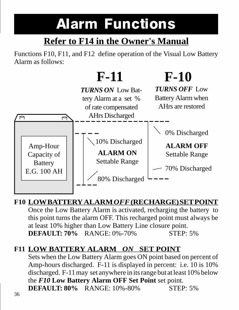
Alarm Functions
F10 LOW BATTERY ALARM OFF (RECHARGE) SET POINTOnce the Low Battery Alarm is activated, recharging the battery tothis point turns the alarm OFF. This recharged point must always beat least 10% higher than Low Battery Line closure point.DEFAULT: 70% RANGE: 0%-70% STEP: 5%
F11 LOW BATTERY ALARM ON SET POINTSets when the Low Battery Alarm goes ON point based on percent ofAmp-hours discharged. F-11 is displayed in percent: i.e. 10 is 10%discharged. F-11 may set anywhere in its range but at least 10% belowthe F10 Low Battery Alarm OFF Set Point set point.DEFAULT: 80% RANGE: 10%-80% STEP: 5%
Amp-HourCapacity of
BatteryE.G. 100 AH
F-10TURNS ON Low Bat-tery Alarm at a set %of rate compensatedAHrs Discharged
ALARM ONSettable Range
70% Discharged
10% Discharged
80% Discharged
F-11TURNS OFF LowBattery Alarm whenAHrs are restored
Refer to F14 in the Owner's ManualFunctions F10, F11, and F12 define operation of the Visual Low BatteryAlarm as follows:
ALARM OFFSettable Range
0% Discharged

37
NOTE: The Low Battery Alarm ON and OFF points oper-ate on rate compensated (Peukert) Amp hours consumed. Oncethe alarm is activated, the battery must be charged until Alarm OFFSet Point is reached to turn the alarm off.
F12LOW V OLTAGE ALARM THRESHOLDF-12 sets the Voltage below which the Low Battery Alarm is activated.But the voltage must remain below this set point for a full 15 secondsbefore the Low Battery Alarm goes ON. Dropping below the LowVoltage Alarm Threshold for less than a full 15 seconds will notactivate the Alarm.If low voltage activates the Alarm while the battery is above theAlarm OFF (Amp-hour) Set Point, the alarm goes OFF as soon asvoltage remains above the low voltage threshold for 15 seconds. If thebattery is below the Alarm OFF (Amp-hour) Set Point when lowvoltages turns the Alarm ON, the alarm stays on until the battery isrecharged to above the Alarm OFF (Amp-hour) Set Point.RANGE: 5.0 - 40V (0 - 50V Scaling) STEP: 0.1V Default 10.5VRANGE: 5.0 - 80V (0 -100V Scaling) STEP: 0.1V Default 10.5VRANGE: 50 - 400V (0 -500V Scaling) STEP: 1.0V Default 105V
THINGS TO REMEMBER:1) The Low Battery Alarm may be activated by either a low Voltage OR
a low Amp-hour condition.2) There must be a 10% difference between the Low Battery Alarm ON
set point and Low Battery Alarm OFF (Recharge) Set Point.3) Because Low Battery Alarm ON may be triggered by rated compen-
sated (Peukert) Amp-hours, you may see fewer Amp-hours re-moved in the numeric display than expected. The more rapidly youhave discharged your battery, the more pronounced this variancewill be.

38
Special versions of Your Meter are available, for additional charge, whichinclude a solid state Alarm Switch to ground via rear panel terminal stripPin #7. This option is use in a variety of settings such as lift pump lockout on fork lifts, two wire generator start/stop, audible low battery alarms,and charge controllers. The additional circuitry of the switch may not beretrofitted to Your Meter in the field. It must be included at the time ofmanufacture.
The Low Battery Alarm Switch goes low to meter ground when the alarmis activated. In other words, a sinking FET switch to the meter's negativepower lead is completed while the alarm is active. This lead is protectedagainst polarity reversal so the "switch" connection has about 1 Ohm ofresistance. This should be taken into account when sizing relays or de-signing logic interfaces. The maximum amount of current which may becontrolled by this circuit is 150 mA (0.150A) at no more than 50V. Beloware two typical applications for the optional Low Battery Alarm Switch:
+ DC Alarm Power.Negative must be commonto Your Meter.
12 V or 24 VPiezo alarm <150 mA.
Optional Alarm Switch
AUDIBLE ALARMRELAY DRIVER DIAGRAM
>
RELAY COIL
To Pin 7, Your Meterrear panel term. strip.
Controlled Circuit
12341234123412341234123412341234123412341234123412341234
To Pin #7Your Meter
1212
Alarm DefeatSwitch On-Off
+ DC Relay Power (<50V). Nega-tive must be common to Your Meter.
^
>
>+ -
39
Peukert's EquationPeukert's Equation describes the effect of different discharge rates on bat-tery capacity. As the discharge rate increases the available battery capac-ity decreases. The table and examples on the following page illustrate thiseffect and how to use the table to estimate the exponent "n". The tables onpages 34 & 35 have typical values of "n" for common batteries.
Making two discharge tests, one at a high discharge rate and one at a lowrate, that bracket your normal range of operation, allows you to calculatean "n" that will describe this varying effect. Your Meter uses an "n" equalto 1.25 which is typical for many batteries.
At some low to moderate discharge rate, typically a battery's 20 hour rate,the logrithmic effect of Peukert's Equation is greatly reduced. The effectof discharge rates smaller than this is nearly linear. Battery manufacturerspecifications of battery capacity in Amp-hours is typically given at the20 hour rate. From this description, if a battery is discharged at this ratefor the period of time called out, you will be able to remove the ratedcapacity.
The equation for Peukert's Capacity (Cp ) is:
By doing two discharge tests and knowing I1 & I
2 (discharge current in
Amps of the two tests), and t1 & t
2 (time in hours for the two tests) you
can calculate n (the Peukert coefficient). You will need a calculator thathas a Log function to solve the equation above. See example on page 35.After you solve for your Peukert's coefficient you may enter it using Ad-vanced Function F8.
C p = I n t wherelog t
2 - log t
1
log I1 - log I
2
n =

40
Peukert's Equation
PERCENTAGE OF AVAILABLE CAPACITY FROM A100 Ahr BATTERY AT DIFFERENT DISCHARGE RATES
USING DIFFERENT PEUKERT'S EXPONENTS
DISCHAGE RATE IN AMPSn 5 1016.7 25 50 75 100 150 200 250 300 400 5001 100 100 100 100 100 100 100 100 100 100 100 100 1001.1 100 93 88 85 79 76 74 71 69 67 66 64 631.2 100 87 78 72 63 58 55 51 48 46 44 42 401.25 100 84 74 67 56 51 47 42 40 37 36 33 321.3 100 81 69 62 50 44 41 36 33 31 30 27 251.4 100 76 61 52 40 34 30 26 23 21 20 17 161.5 100 71 55 45 32 26 22 18 16 14 13 11 10
Example #1: Suppose you have a 200Ahr battery. Now discharge at a 50Amp rate until the battery reaches1.75V per cell (10.5V for a 12V bat-tery). This would be equalivent to adischarge rate of 25A for a 100 Ahrbattery. If the battery delivered 67%(134Ahr) the appropriate Peukert'sexponent would be 1.25.
Example #2: A 100 Ahr bat-tery with a Peukert's exponentof 1.3 will deliver only 41% ofits capacity when supplying a100A load.
EX
PO
NE
NT
The table below may be used to understand the effect of high rates ofdischarge on available battery capacity. It may also be used to estimatethe exponent "n" for a battery after a single discharge test. The table isbased on a 100 Ahr battery but may be used for any capacity battery byusing an appropriately scaled current. See the examples below:

41
Typical Values for Peukert's Exponent "n"This table contains values for the exponent "n" for various batteries andmanufactures. They are calculated from the 20 hour rating and the Re-serve Minutes @ 25A as supplied by the manufacturer. They should beconsidered only a guide for selecting "n".
Prevailer & SeaGel BatteriesModel Volts Res. Min. 20 Hr. rating "n"8GGC 6 375 180 1.148GU1 12 43 43 1.208GU24 12 130 70 1.138GU27 12 167 86 1.128GU30H 12 188 95 1.1284D 12 388 180 1.118G8D 12 500 225 1.10
Trojan BatteriesModel Volts Res. Min. 20 Hr. rating "n"T-105 6 447 225 1.24T-125 6 488 235 1.19T-145 6 530 244 1.14J250 6 535 250 1.17J305 6 660 305 1.21L16 6 760 350 1.2824TM 12 135 85 1.2327TM 12 160 105 1.2830XHS 12 225 130 1.27SCS225 12 225 130 1.27EV8D 12 450 216 1.17
Peukert's Equation
Peukert's Exponent

42
Surrette and Rolls BatteriesModel Volts Res. Min. 20 Hr. rating "n"EHG-208 6 345 208 1.42EIG-225 6 350 225 1.54*EIG-262 6 395 262 1.72*24/90 12 165 90 1.1627/12M 12 190 112 1.2330H/108 12 230 108 1.08HT/4D 12 348 170 1.15HT/8D 12 450 221 1.20
*Use Max allowed "n" of 1.50
Peukert's Exponent
log t2 - log t
1
log I1 - log I
2
n =log 20 - log 7.45
log 25 - log 11.25 = =
1.301 - 0.872
1.398 - 1.051 = 1.24
Example of using Reserve Minutes @ 25 Ampsand the 20 hour rate to calculate "n".
First convert Reserve Minutes to hours, then find the discharge current atfor the 20 hour rating. Finally use a calculator to solve the arithmetic.
Trojan T-105:Reserve Minutes = 447 min @ 25 Amps.
t1
= 447 min = 447/60 = 7.45 hrs
I1
= 25 Amps
20 Hour rating = 225 Ahr
t2
= 20 hours
I1
= 225 Amp-hours/20 hours = 11.25 Amps

43
TroubleshootingCondition SuggestionNo lights or display Check Power Connections
Reset meter (Page 32)No keyboard response Check Lock is not invoked
Reset meter (Page 32)Time Remaining Not Check Battery Capacity (Page 21)Accurate Check Temperature Coef. (Page 35)
Check Peukert Exponent (Page 26)Digital Display Dim Clean front panel photo-sensor
(Between A and Ah lights)Current Polarity Reversed Current Shunt leads reversed. (Page 13)Intermittent Operation Corrosion or loose wires. Loosen and
reconnect all rear panel connections.Check voltage sense and shunt wiringat battery location.
Accumulates Negative Charge Parameters not met. CheckAmp-hour reading Charged Parameter values, Has 100% of
Kwhrs been returned? Charging Current isnot passing through shunt. (Pages 13,22,23,& Function F04)
CECO warrants that Your Meter will measure Voltage, Amperage, andAmp-Hours within the published specifications. The Time remaining andLED bar graph functions are complicated and require appropriate user setup and are therefore beyond the control of CECO and are not covered bywarranty. Similarly installation wiring and specific applications are be-yond our control and are not covered by warranty. See Page 51.

44
Options & Versions
User installable OPTIONS available include:
Prescalers: Extend the voltage range covered by Your Meterto either 0-100V (CECO Part #900087) or0-500V (CECO Part #900086).
Temperature Sensor: Reports battery temperature in Degrees Celcius(CECO Part #900105)
All other options must be installed at the time Your Meter is manufac-tured as additional circuitry is involved.
Special order VERSIONS of Your Meter
RS-232 (9600,8,N,1 ASCII computer port)
Alarm Switch Switch closure when Low Battery Alarm is active.
RS-232 + Alarm Switch (Both options above)
If you need to log data from an RS-232 equipped version of Your Meter,ask your dealer about Cruising Equipment Company's Memory Module.This is a 1 MB data logger which captures data once per second, onceeach 10 seconds, once per minute or once each 10 minutes. It's ideal forproof of performance logging for PV and wind systems. If you are devel-oping electric vehicles, ask about the Memory Module w/GPS. In addi-tion to data logging, this specialized data logger uses the Global Position-ing System to record precise time and vehicle speed.

45
+
+
-
-
High Voltage PrescalerCAUTION!
1. Installation of the Prescaler Option involves work with poten-tially fatal voltages. NEVER work alone: Have at least one personpresent who can render assistance and CPR in the event of an acci-dent. If you have any doubt about your qualifications to work on ahigh voltage system, DON'T DO IT!
2. When working with any DC system, even so-called ungrounded("floating") systems with no planned chassis connection, discon-nect the negative battery terminal first.
HVBattery
Prescaler
Note: Black wires are common within Prescaler.
Warning: Reversing inputvoltage destroys Prescaler
and voids warranty.
Shunt
Black
Red(Tagged)
Black
2A Fuse. Above 250Vuse 500V rated fuse.
Prescaler Part Numbers:0-100V Part # 9000870-500V Part # 900086
To Your
Meter
To Your
Meter
Use a Prescaler if system voltage EVER exceeds 50V!Then set voltage scaling with F13 (See Page 50).
Red(Tagged)
46
Electric Vehicles (EV's)
Your Meter is the ideal energy meter for EV instrumentation. It not onlyprovides Volts, Amps, Amp-hours and Time Remaining, it adds two im-portant bonuses: Kilowatt-hours and optional serial computer output.
If you design or work with electric vehicles or battery powered equip-ment of any type, you should realize that Kilowatt-hours are a more accu-rate measure of energy used than are Amp-hours. Here's why:
The term "Amp-hour" defines current (Amps) multiplied by time (hours).Amp-hours is one way to state battery capacity. Amp-hours is not a mea-sure of energy consumed by a vehicle. Energy is defined as:
Energy in Watt-hours = Voltage x Amperage x time.Consider two examples: First, assume we have a 120 Volt battery thatsupplies a 100 Amp load for 1 hour. At the end of one hour, 12,000 Watt-hours (12.00 Kwhrs) will have been consumed. In the same period oftime, 100 Amp-hours will be used.
But now suppose we have a 240 Volt battery supplying a 100 Amp loadfor one hour. What happens to the math? Well, 24,000 Watt-hours (24.00Kwhrs) of power have been consumed. The Amp-hours consumed is thesame as the first example, 100 Amp-hours, but twice the energy has beenconsumed!
That's why electric vehicle efficiency is judged on Kilowatt-hours. A Kilo-watt-hour is a 1,000 watt load for a period of one hour. You buy kilowatt-hours from the power company (to keep the lights on in your home) at atypical cost of $0.05 to $0.15 per KWh. By comparing the cost of Kilo-watt-hours from the electric company with Kilowatt-hour consumptionof an electric vehicle, you can accurately judge EV operating costs.
Refer to Owner's Manual for instructions on use of the KWh display.

47
+
-
-
-
+
+
EV Installations
HVBattery
Prescaler
Black
Black
Red (Tagged)
Red(Tagged)
5 6 7 81
2 3 456
7
8
Acces.Battery
DC - DCConverter
43
2
1
+12V Meterpower goes
to Pin #5
The negative of Your Meter's power supply must be common to the nega-tive of the battery (motive pack) which you are measuring. This may posedifficulty if your electric vehicle uses an "unbonded" or "floating" [noconnection to the chassis] motive pack and a "bonded" [connected to thechassis] accessory battery. In these instances, the use of a DC-DC con-verter, or a separate battery with a common negative with the motivebattery is required. This device provides power for Your Meter withoutelectrically connecting the motive battery negative to the chassis. Thediagram shown is for a DC-DC converter typically supplied by CruisingEquipment Company (Part # 313075). If you use a different DC-DC con-verter, the pin-out may be different:
2A Fuse. Above 250Vuse 500V rated fuse.
Shunt YourMeter
12V
Warning: Reversinginput voltage destroysPrescaler and voids
warranty.
DC-DC Converter pin outs vary.
+HV scaledvoltages goes
to Pin #4
48
+
-
-
-
+
+
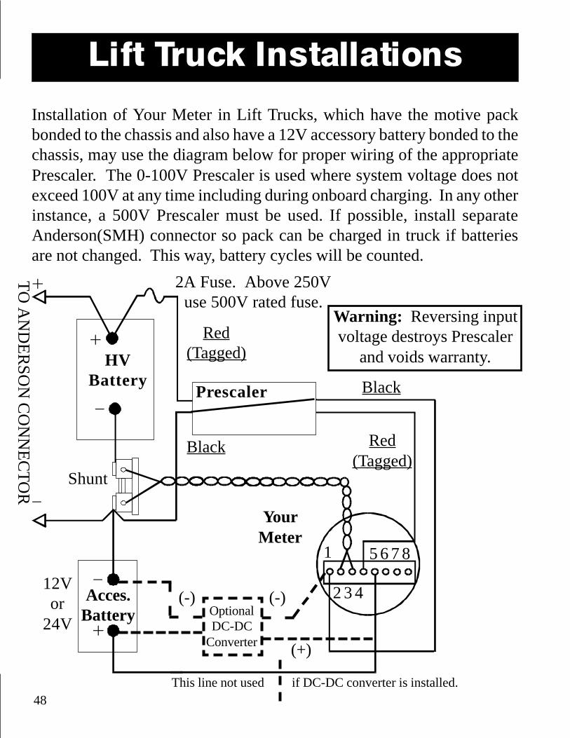
Lift Truck Installations
Installation of Your Meter in Lift Trucks, which have the motive packbonded to the chassis and also have a 12V accessory battery bonded to thechassis, may use the diagram below for proper wiring of the appropriatePrescaler. The 0-100V Prescaler is used where system voltage does notexceed 100V at any time including during onboard charging. In any otherinstance, a 500V Prescaler must be used. If possible, install separateAnderson(SMH) connector so pack can be charged in truck if batteriesare not changed. This way, battery cycles will be counted.
HVBattery
Prescaler
Black Red(Tagged)
Black
Red(Tagged)
2 3 4
5 6 7 81
Acces.Battery
2A Fuse. Above 250Vuse 500V rated fuse.
YourMeter
Shunt
12Vor
24V
Warning: Reversing inputvoltage destroys Prescaler
and voids warranty.
TO
AN
DE
RS
ON
CO
NN
EC
TO
R
This line not used if DC-DC converter is installed.
OptionalDC-DC
Converter
(-)(-)
(+)

49
(optional)Serial Port, RS-232Your Meter may be equipped to transmit serial communications data to a per-sonal computer or a data logging device, such as our Memory Module. Whenequipped with the optional RS-232 port, Your Meter will transmit a data mes-sage once a second. The structure of this data is as follows:
Data Rate: 9600 Data Bits: 8Stop Bits: 1 Parity Bits: NoneWord: ASCII Characters, comma delimited
Output Format:Time, KWhrs, Amps, Volts, Ahrs, Peukert Ahrs, Peukert Amps, Time remain-ing, Bar Graph state, Temperature (degrees C.)
Time is elapsed seconds since last Amp-hour reset. Kilowatt-hours are signed +or -, Amp-Hours are signed + or -, Amps are signed + or -, Volts are positive,time remaining is in hours or tenths of hours.Peukert Amps and Peukert Amp-hours are compensated for Peukert's equation.These numbers are primarily intended for our development and troubleshoot-ing. Please do not attempt to interpret these numbers.The Bar Graph state is indicated by the following integers:1<20%, 2<40%, 3<60%, 4<80%, 5<100%, 6 = Full (Charged Params met)If the Low Battery Output is activated, the Bar Graph state is indicated as:A<20%, B<40%, C<60%, D<80%, E<100%, F = Full (Charged Params met)
Pin Out:The serial connection is via the DB-9 connector on the rear deck of Your Meter.See additional notes on Page 11. The pin connections are as follows:
Pin 2 Receive Data linePin 3 Transmit Data linePin 5 Ground This is connected to battery pack (-).The shell of the DB-9 is NOT grounded.

50
High Voltage Notes
IF YOU USE MOTIVE BATTERIES TO POWERYOUR METER:
If the HV battery is "tapped" to provide meter power, it is recommendedthat a 24V tap, not a 12V tap, be used. The reason for this is that underheavy acceleration under low battery conditions, voltage may fall to levelslow enough to cause the meter display to turn off momentarily. Underextreme circumstances, historical data may also be lost.
AVOID DATA LINE SHOCK HAZARD:
If you have a floating ground system and Your Meter is equipped with theRS-232 Serial Computer Port option and is being used to record data intoa laptop computer, we strongly recommend use of an optical isolator suchas Omega Cat #268 to eliminate danger of a HV short to ground or per-sonal shock hazard. Use caution in connecting wires to the DB-9 on therear of Your Meter as Pin #5 is connected directly to motive battery (-).
F13 SET VOLTAGE SCALINGSets proper voltage scaling when used with an external VoltagePrescaler. NOTE: If you use a Prescaler, you need to change theCharged Voltage to an appropriate value for your application. SeePages 21 & 22 of Owner's Manual - "Charged Parameters".DEFAULT: 0= 0-50V. Options: 1= 0-100V, 2= 0-500V
HOW TO SET VOLTAGE SCALING WHENUSING A HIGH VOLTAGE PRESCALER

51
EC Declaration ofConformity
CEManufacturer: Cruising Equipment Co.
Address: Cruising Equipment Co.5245 Shilshole Ave. NWSeattle, WA 98107U.S.A.
Herewith declares that: E-Meter Battery State of Charge Meters
Models: E-Meter Link 10Battery Monitor DCM-1000Energy Manager CheckmateBatt-Meter
Is in conformity with the provision of the EEC DirectiveEMC 89/336/EEC and amendments 92/31/EEC, 93/68/EEC.The following harmonized standards have been applied:
EN 50081-1: 1992EN 50082-1: 1992

52
The purchase of Your Meter includes one 15 minute phone call. Youmust have a serial number to access the service department. Subsequentcalls will be billed at $1.00/minute with a $15.00 minimum. Please haveyour Mastercard or Visa ready. This policy is strictly enforced in an effortto keep the product cost as low as possible. Our experience is that morethat 90% of problems are installation or operation related that could havebeen solved by reading this manual. You may also contact your dealer orthe OEM whose name appears on the front of Your Meter for support.
Cruising Equipment Co. (CECO) warrants to the original purchaser only for 18 months from thedate of purchase that Your Meter (hereafter Meter) will be in good working order when properly installed andoperated as described in this Manual.
If your Meter fails to perform or becomes defective under normal use and service, CECO, will, withoutcharge, at CECO’s place of business, within a reasonable time after delivery, repair, or at CECO’s option, replacewith a new or factory reconditioned part any part found defective.
In order to avail yourself of the warranty you must:1. Contact: & Obtain warranty authorization from CECO (Address below.)2 Ship the Meter, charges prepaid, with proof of purchase within 18 months of its sale to you.
This warranty is void and will not apply if:1. Your Meter has been modified, repaired, or opened without written authorization from CECO:2. The identification markings on your Meter have been altered or removed:3. Your Meter has been damaged through abuse, neglect, exposure to sea spray, lighting strikes, high voltage,accident, voltage reversal.4. Your Meter was not installed and operated according to the owner’s manual or was operated under conditionsmore severe than those specified in the owners manual.
THE FOREGOING WARRANTY IS IN LIEU OF ALL OTHER WARRANTIES, INCLUDINGTHE WARRANTIES OF FITNESS FOR A PARTICULAR PURPOSE AND MERCHANTABILITY,EXPRESS OR IMPLIED, AND OF ALL OBLIGATIONS OR LIABILITIES ON THE PART OF CECOFOR DAMAGES, INCLUDING, BUT NOT LIMITED TO LOSS OF TIME, INCONVENIENCE,COMMERCIAL LOSS OR CONSEQUENTIAL DAMAGES, WHICH MAY ARISE OUT OF, OR INCONNECTION WITH, THE USE OR PERFORMANCE OF THE METER.
Some states do not allow the exclusion or limitation of incidental or consequential damages, and somestates do not allow limitations on how long and implied warranty lasts, so if the law of that state applies, the abovelimitation or exclusion may not apply to you. This warranty gives you specific legal rights and you may also haveothers which vary from state to state.
Cruising Equipment Company5245 Shilshole Ave. N.W. Seattle, WA 98107 USATelephone: (206) 782-8100 Fax: (206) 782-4336
Limited Warranty

53
RS-232 Warning
When using an RS-232 equipped version of Your Meter in anelectric vehicle which has a floating motive battery negative, re-member that Pin #5 of the DB-9 connector coming out of theback of Your Meter is connected to the motive battery negative.
This normally causes no problem when used with our MemoryModules or with laptop computers. However, if you plug theDB-9 RS-232 output into a computer with a metal chassis thenmotive battery negative will be connected to the chassis of thecomputer.
THIS EXPOSED BATTERY NEGATIVE MAY BEHAZARDOUS, AND POSSIBLY FATAL IF YOU
HAVE A HIGH SIDE MOTIVE PACK FAULT.
We strongly recommend that when using a Memory Module orcomputer to log data, you minimize the hazard by installing anRS-232 Opto-Isolation Module. One such module is availablethrough OMEGA ELECTRONICS (Model 268 cost $126).Omega's phone number is 1-800-848-4271.
Please note you will also have to purchase DB-25 to DB-9 adapt-ers as Model 268 uses DB-25 connectors. Be certain you pur-chase straight through adapters, not the null modem type!

54
NOTES

55
NOTES

56
FeaturesMulticolor Bar Graph Display
Time Remaining Display
Amp-Hours consumed
Digital Volt & Amp Meter
LED shows active display
Custom Setup Capability
Lockable Front Panel Display
Splashproof!
If you can drill 1 hole...Connect 5 wires....Follow a few simple instructions....
You can have theUltimate Battery Monitor!
The Battery Monitorthat's EASY TO INSTALL!
Mfg. by: Cruising Equipment Company5245 Shilshole Ave. NW, Seattle, WA 98107 U.S.A. Phone: (206) 782-8100 Fax: (206) 782-4336
Visit our web site at: http://www.cruisingequip.com