Embed Size (px)
Citation preview
.
Owner’s Manual & Technical Information
KNNS0001
2
.2.4GHz Radio System
LegalEntire contents ©2015 IKONNIK RC
Before using your product, review all documentation and inspect the product carefully. If for some reason you decide it is not what you wanted, then do not continue with unpacking, setup or operation of your product. Your local hobby dealer cannot accept a product for return or exchange after partaking in actions that produce wear and tear.
Read, understand and follow all instructions and accompanying material carefully before operating or assembling your product to prevent serious damage. Failure to complete these tasks properly or intentional aversion to the content will be considered abuse and/or neglect.
Product specifications are subject to change without notice. Due to ongoing development, the actual product may vary from images shown.
This product contains chemicals known to the State of California to cause cancer, birth defects and other reproductive harm.
This product is not a toy! (14+) Recommended for ages 14 and up. Adult supervision required for ages under 18 years old. Contains small parts, keep out of reach of children 3 years of age and younger.
Important InformationThroughout this manual you will see different notes, cautions and warnings to help alert you to important information about the section you are reading. Please see below for the descriptions and what to look for to identify each type.
WARNING: THIS INFORMATION IS IMPERATIVE FOR YOU TO UNDERSTAND AND FOLLOW AS LACK OF COMPLIANCE WITH THE CONTENTS OF THE WARNING COULD CAUSE PERSONAL INJURY OR PROPERTY DAMAGE.
CAUTION: THIS INFORMATION IS IMPORTANT FOR YOU TO UNDERSTAND AND FOLLOW AS LACK OF COMPLIANCE WITH THE CONTENTS OF THE CAUTION COULD CAUSE DAMAGE TO YOUR PRODUCT THAT IS NOT COVERED UNDER WARRANTY.
Note/Tip: This information is important for you to keep in mind, most commonly used to recall previously given information or to direct you to or provide you with additional information on a subject.
3
Contents
Notice .......................................................................................... 4
Precautions................................................................................. 4
Introduction ................................................................................ 5
Features ...................................................................................... 5
Receiver Installation and Connection ....................................... 7
Pairing the Transmitter and Receiver ....................................... 8
Channel Reverse (REV) .............................................................. 9
Digital Trim Settings ................................................................... 9
End Point Adjustment (EPA).....................................................10
Steering Dual-Rate (ST D/R) ....................................................11
2.4 GHz Fail-Safe Adjustment for Channel 2 .........................11
Beginner Mode and Feature Lock ...........................................11
10 Model Memory with Pair Safe Technology ........................12
Memory Reset ..........................................................................12
Power Alarm and Automatic Shut-Down .................................13
Battery Replacement and Options ..........................................13
Calibrating ESCs .......................................................................14
Standard Operation..................................................................14
Using Your Transmitter For The First Time ..............................15
General Care ............................................................................16
Maintenance ............................................................................16
Storage and Disposal .............................................................. 17
Troubleshooting Problems ....................................................... 17
Appendix ...................................................................................18
Warranties ................................................................................25
4
.2.4GHz Radio System
NoticeYour IKONNIK product is calibrated, paired and tested at the factory prior to final packaging, some issues may arise during shipping and handling that can be easily resolved at home. For other adjustments it should be known that hobby grade radio controlled products such as those offered by IKONNIK differ from toy grade, in that they are intended to be user-serviceable products where the user can program, disassemble and maintain their own product. We try our best to ensure the information you need to introduce you to this form of product ownership is available to you though this manual. Please see the troubleshooting guide at the back of this manual for assistance in resolving issues, either as they are experienced out of the box or as found after regular use.
Note: Assuming your product functions properly as intended out of the box, the best thing you can do is pay close attention to how it feels, sounds and functions. This will help you identify problems later since you will have a reference of how the product is supposed to perform.
If you require further information or assistance resolving a possible issue, please consult the warranty card included with your product.
PrecautionsWARNING: ALWAYS KEEP LOOSE CLOTHING, HAIR, TOOLS OR OTHER MOVABLE OBJECTS AWAY FROM MOVING PARTS OF YOUR VEHICLE DURING SETUP AND CONFIGURATION. SPINNING TIRES CAN EXPAND AND MAKE CONTACT WITH SMALL TOOLS, OR HARDWARE AND SEND THEM FLYING AT HIGH SPEEDS RISKING INJURY TO YOU OR OTHERS AROUND YOU.
• Your model can cause serious damage or injury so please use caution and courtesy when operating your model.
• As a safety precaution, perform all transmitter (Tx) and receiver (Rx) adjustments with all parts of the vehicle off the ground. This ensures the complete control over the vehicle at all times during adjustments.
• Do not operate your model near traffic, bystanders, parking areas, or any other area that could result in injury to people or damage to property.
• If at any time during the operation of your model you observe any erratic or abnormal behavior of your model, immediately stop operation and bring the mode to a safe stop in a safe location to diagnose the problem.
• Always power on your transmitter before turning your vehicle on.
• If you have little or no experience operating R/C models, we strongly recommend you seek the assistance of your local hobby dealer.
• Do not expose the transmitter to water or excessive moisture.
• Do not operate radio controlled products in a lightning or thunder storm.
• Ensure your batteries (both Tx and vehicle) are charged before each use.
• Check all servos and electrical connections prior to each use.

5
R/C models are an extremely fun hobby, but safety should never be ignored or taken lightly. Always take caution when operating your model as damage to property and injury can result from careless operation. Please consult your local hobby dealer with any questions or troubleshooting issues. And of course don’t forget to have fun, you deserve it after reading through all of these safety tips!
IntroductionThe IKONNIK ET4 transmitter was engineered with great ergonomics for ultimate comfort and to allow its use by the most people possible. While being packed with high-end software functions is great; if you can’t physically use the transmitter or if it is uncomfortable, what good will the technology bring you? Understanding this dilemma we began the development of the ET4 with the physical needs of the users in mind. The transmitter is configurable for use by left-or right-hand users of most hand sizes. Included are 3pcs of rubber grips that can be changed to suit your hand size. These were designed to fit the small hands of children and also the larger hands of adults. The Wheel module can be flipped from side to side and repositioned fore or aft for comfort or placed up high. A wheel installed in a lower position is best for ergonomics and synchronization of your hands. The ideal position for your hands is to have your wrists comfortably aligned both in height and distance from your body while holding the transmitter. The ET4 provides many options to configure the wheel position to best suit your body. The default configuration is the most common and a good place to start. We highly recommend configuring your radio system prior to making changes to the wheel position or placement. This will enable you to confirm the proper function and help with troubleshooting should any issues arise after making a physical change. See the appendices at the back of this manual for assistance in adjusting the ergonomics of your new transmitter.
Ready to expand your collection? The IKONNIK ET4 is equipped with our proprietary 2.4GHz Xenon protocol. This means that any product containing the IKONNIK Xenon logo will easily pair with one of the models of your radio. No more need to take multiple transmitters with you when one will do.
6
.2.4GHz Radio System
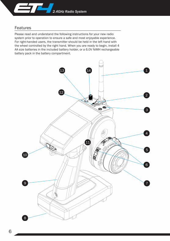
FeaturesPlease read and understand the following instructions for your new radio system prior to operation to ensure a safe and most enjoyable experience. For right-handed users, the transmitter should be held in the left hand with the wheel controlled by the right hand. When you are ready to begin, install 4 AA size batteries in the included battery holder, or a 6.0V NiMH rechargeable battery pack in the battery compartment.

7
1. Antenna: Transmits signal to the receiver located in the vehicle. Flip up when transmitter in use. Fold for storage.
2. Multifunction Red Indicator LED:a. Power indicator.
b. Low battery voltage warning, batteries should be replaced/recharged before continued use when flashing.
c. Model indicator.
3. Dual-Rate Adjustment/Memory Reset: Adjusts total travel of servo in both directions.
4. Ch. 4/Fail-Safe: Toggle Ch. 4 ON/OFF. Use to set the Fail-Safe in case of signal loss.
5. REV/Pair:a. Use to reverse servo/channel operation.
b. Use to put the transmitter into pairing mode.
6. Digital Trim: All switches are digital so there is no need to readjust trim position for different models after initial setup.a. Steering: Controls the “hands-off” left/right direction of the vehicle.
b. Throttle: Adjusts the motor speed to STOP when trigger is in ‘hands-off’ (neutral) position.
7. Steering Wheel: Controls left/right motion (note that the wheel can be re-positioned and/or configured for left-hand use.
8. Battery compartment: Houses [4] AA batteries or a NiMH rechargeable battery pack for powering the transmitter.
9. Adjustable Grip: For holding the transmitter. Use included grip sizes to adjust for your hand size.
10. ON/OFF Switch: Turns the power ON/OFF for the transmitter.
11. Throttle Trigger: Controls forward/reverse/brake motion (designed to be operated with index finger).
12. Mode Switch:a. Standard Mode: All functions are fully operational.
b. Feature Lock: Disables all buttons except Steering Trim.
c. Beginner Mode: Reduces throttle output to 50%.
13. Model Select: Use to select a model when powering ON the transmitter.
14. Channel 3 adjustment knob.
8
.2.4GHz Radio System
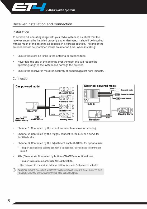
Receiver Installation and Connection
InstallationTo achieve full operating range with your radio system, it is critical that the receiver antenna be installed properly and undamaged. It should be installed with as much of the antenna as possible in a vertical position. The end of the antenna should be contained inside an antenna tube. When installing:
• Ensure there are no kinks in the antenna or antenna tube.
• Never fold the end of the antenna over the tube, this will reduce the operating range of the system and damage the antenna.
• Ensure the receiver is mounted securely or padded against hard impacts.
Connection
•
Channel 1: Controlled by the wheel, connect to a servo for steering.
• Channel 2: Controlled by the trigger, connect to the ESC or a servo for throttle/brake.
• Channel 3: Controlled by the adjustment knob (0-100%) for optional use.
▪ This port can also be used to connect a transponder device used in controlled racing.
• AUX (Channel 4): Controlled by button (ON/OFF) for optional use.
▪ This port is most commonly used for LED light kits.
▪ Use this port to connect an external battery for use in fuel powered vehicles.
CAUTION: NEVER CONNECT A BATTERY WITH VOLTAGE HIGHER THAN 6.0V TO THE RECEIVER, DOING SO COULD DAMAGE THE ELECTRONICS.
9
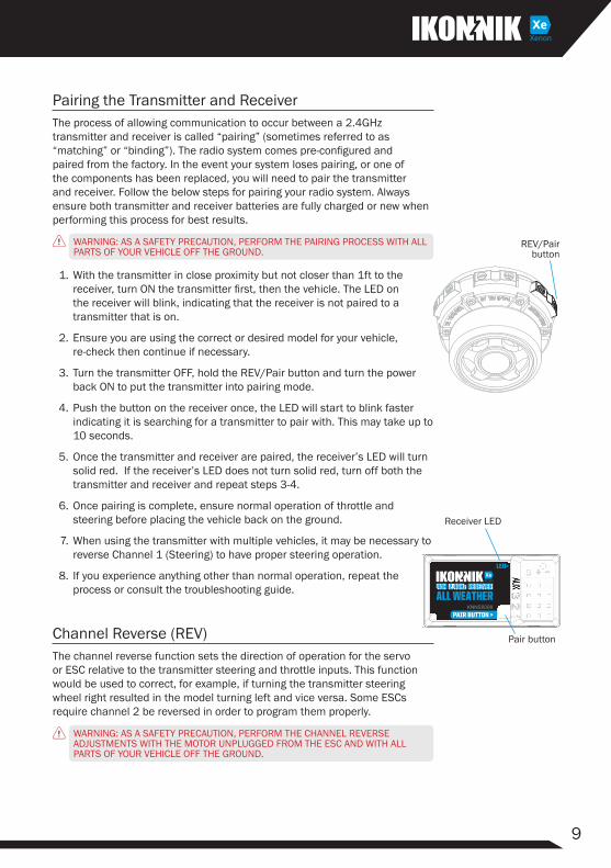
Pairing the Transmitter and ReceiverThe process of allowing communication to occur between a 2.4GHz transmitter and receiver is called “pairing” (sometimes referred to as “matching” or “binding”). The radio system comes pre-configured and paired from the factory. In the event your system loses pairing, or one of the components has been replaced, you will need to pair the transmitter and receiver. Follow the below steps for pairing your radio system. Always ensure both transmitter and receiver batteries are fully charged or new when performing this process for best results.
WARNING: AS A SAFETY PRECAUTION, PERFORM THE PAIRING PROCESS WITH ALL PARTS OF YOUR VEHICLE OFF THE GROUND.
1. With the transmitter in close proximity but not closer than 1ft to the receiver, turn ON the transmitter first, then the vehicle. The LED on the receiver will blink, indicating that the receiver is not paired to a transmitter that is on.
2. Ensure you are using the correct or desired model for your vehicle, re-check then continue if necessary.
3. Turn the transmitter OFF, hold the REV/Pair button and turn the power back ON to put the transmitter into pairing mode.
4. Push the button on the receiver once, the LED will start to blink faster indicating it is searching for a transmitter to pair with. This may take up to 10 seconds.
5. Once the transmitter and receiver are paired, the receiver’s LED will turn solid red. If the receiver’s LED does not turn solid red, turn off both the transmitter and receiver and repeat steps 3-4.
6. Once pairing is complete, ensure normal operation of throttle and steering before placing the vehicle back on the ground.
7. When using the transmitter with multiple vehicles, it may be necessary to reverse Channel 1 (Steering) to have proper steering operation.
8. If you experience anything other than normal operation, repeat the process or consult the troubleshooting guide.
Channel Reverse (REV)The channel reverse function sets the direction of operation for the servo or ESC relative to the transmitter steering and throttle inputs. This function would be used to correct, for example, if turning the transmitter steering wheel right resulted in the model turning left and vice versa. Some ESCs require channel 2 be reversed in order to program them properly.
WARNING: AS A SAFETY PRECAUTION, PERFORM THE CHANNEL REVERSE ADJUSTMENTS WITH THE MOTOR UNPLUGGED FROM THE ESC AND WITH ALL PARTS OF YOUR VEHICLE OFF THE GROUND.
REV/Pair button
Receiver LED
Pair button

10
.2.4GHz Radio System
Steering Reverse1. Turn the steering wheel completely to the left (or right) and press the
“REV” button for at least 3 seconds to reverse channel 1.
2. The transmitter will beep once for confirmation of “Normal” and twice for confirmation of “Reverse” setting.
Throttle Reverse1. Pull the throttle trigger completely to full throttle (or push forward for full
brake) and press the “REV” button for at least 3 seconds to reverse the Throttle (TH) channel.
2. The transmitter will beep once for confirmation of “Normal” and twice for confirmation of “Reverse” setting.
Digital Trim SettingsThe channel trims of your models are stored in memory and do not need to be adjusted every time a model is re-selected.
Steering Trim (Channel 1): Use trim to ensure the vehicle can track straight with no steering input
Throttle Trim (Channel 2): Use trimmed so the vehicle is stationary when no throttle input is applied
• Press the (+) or (-) buttons for each channel to adjust the trim setting. A long beep will sound when the neutral position is reached.
• Once the trim setting reaches its limit, a long steady “beep” will sound.
End Point Adjustment (EPA)End points are used to set the maximum travel for their respective channel. Steering end points are used to independently adjust the left and right steering angles relative to the steering wheel position. To adjust them both at the same time, see the section on Steering Dual-Rate. Throttle end points are used to independently adjust the full throttle and full brake position for an ESC or throttle servo. The end points are set by moving the transmitter control to its maximum position and using the corresponding (+) or (-) buttons to adjust the end point.
Note: The steering dual-rate should be set to 100% prior to setting steering EPA.
Steering EPACAUTION: BE CAREFUL TO NOT OVER-EXTEND THE STEERING THROW AS IT CAN CAUSE YOUR SERVO TO OVER-WORK AND OVER-HEAT.
• Turn the steering wheel completely to the left and use the ‘ST+’ or ‘ST-’ buttons to adjust the steering angle of the vehicle to maximum (sometimes this will require reducing the travel).
• Repeat this process for turning the wheel right.
REV/Pair button
Steering Trim button
Throttle Trim button
Steering EPA buttons
11
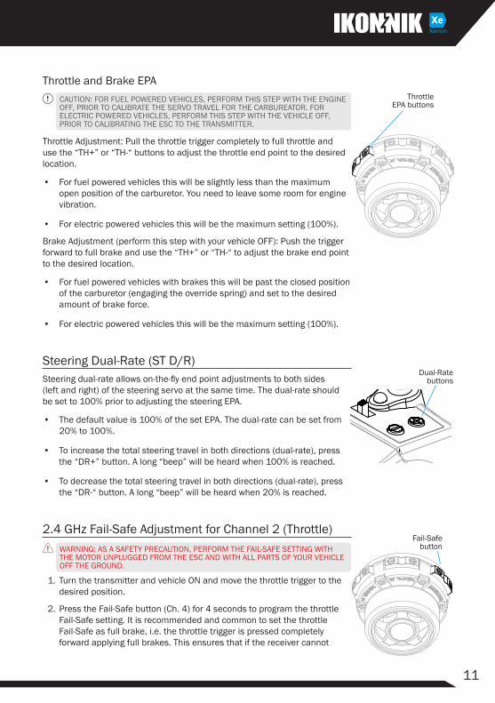
Throttle and Brake EPACAUTION: FOR FUEL POWERED VEHICLES, PERFORM THIS STEP WITH THE ENGINE OFF, PRIOR TO CALIBRATE THE SERVO TRAVEL FOR THE CARBUREATOR. FOR ELECTRIC POWERED VEHICLES, PERFORM THIS STEP WITH THE VEHICLE OFF, PRIOR TO CALIBRATING THE ESC TO THE TRANSMITTER.
Throttle Adjustment: Pull the throttle trigger completely to full throttle and use the “TH+” or “TH-“ buttons to adjust the throttle end point to the desired location.
• For fuel powered vehicles this will be slightly less than the maximum open position of the carburetor. You need to leave some room for engine vibration.
• For electric powered vehicles this will be the maximum setting (100%).
Brake Adjustment (perform this step with your vehicle OFF): Push the trigger forward to full brake and use the “TH+” or “TH-“ to adjust the brake end point to the desired location.
• For fuel powered vehicles with brakes this will be past the closed position of the carburetor (engaging the override spring) and set to the desired amount of brake force.
• For electric powered vehicles this will be the maximum setting (100%).
Steering Dual-Rate (ST D/R)Steering dual-rate allows on-the-fly end point adjustments to both sides (left and right) of the steering servo at the same time. The dual-rate should be set to 100% prior to adjusting the steering EPA.
• The default value is 100% of the set EPA. The dual-rate can be set from 20% to 100%.
• To increase the total steering travel in both directions (dual-rate), press the “DR+” button. A long “beep” will be heard when 100% is reached.
• To decrease the total steering travel in both directions (dual-rate), press the “DR-“ button. A long “beep” will be heard when 20% is reached.
2.4 GHz Fail-Safe Adjustment for Channel 2 (Throttle)WARNING: AS A SAFETY PRECAUTION, PERFORM THE FAIL-SAFE SETTING WITH THE MOTOR UNPLUGGED FROM THE ESC AND WITH ALL PARTS OF YOUR VEHICLE OFF THE GROUND.
1. Turn the transmitter and vehicle ON and move the throttle trigger to the desired position.
2. Press the Fail-Safe button (Ch. 4) for 4 seconds to program the throttle Fail-Safe setting. It is recommended and common to set the throttle Fail-Safe as full brake, i.e. the throttle trigger is pressed completely forward applying full brakes. This ensures that if the receiver cannot
Fail-Safe button
Throttle EPA buttons
Dual-Rate buttons
12
.2.4GHz Radio System
receive a signal from the transmitter, the servos or ESC will default to full brake causing the vehicle to stop.
3. To test the Fail-Safe settings, turn the transmitter OFF while the receiver is ON. The servo/ESC will default to its programmed positions and the motor should not spin (assuming you have set the Fail-Safe to full brake).
Note: Each model memory has its own unique fail-safe setting so they each need to be set independently.
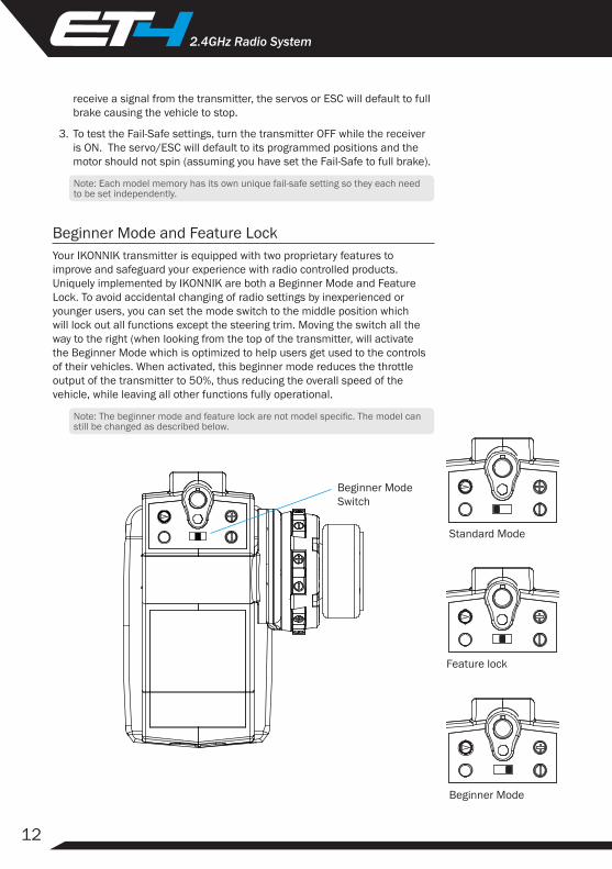
Beginner Mode and Feature LockYour IKONNIK transmitter is equipped with two proprietary features to improve and safeguard your experience with radio controlled products. Uniquely implemented by IKONNIK are both a Beginner Mode and Feature Lock. To avoid accidental changing of radio settings by inexperienced or younger users, you can set the mode switch to the middle position which will lock out all functions except the steering trim. Moving the switch all the way to the right (when looking from the top of the transmitter, will activate the Beginner Mode which is optimized to help users get used to the controls of their vehicles. When activated, this beginner mode reduces the throttle output of the transmitter to 50%, thus reducing the overall speed of the vehicle, while leaving all other functions fully operational.
Note: The beginner mode and feature lock are not model specific. The model can still be changed as described below.
Beginner Mode Switch
Beginner Mode
Standard Mode
Feature lock
13
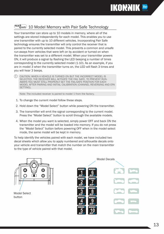
10 Model Memory with Pair Safe TechnologyYour transmitter can store up to 10 models in memory, where all of the settings are stored independently for each model. This enables you to use one transmitter with up to 10 different vehicles. Incorporating Pair Safe technology ensures the transmitter will only control the receiver that is paired to the currently selected model. This prevents a common and unsafe run-aways from vehicles that were left on by accident or turned on when the transmitter was set to a different model. When your transmitter powers ON, it will produce a signal by flashing the LED beeping a number of times corresponding to the currently selected model (1-10). As an example, if you are in model 3 when the transmitter turns on, the LED will flash 3 times and you will hear 3 beeps.
CAUTION: WHEN A VEHICLE IS TURNED ON BUT THE INCORRECT MODEL IS SELECTED, THE RECEIVER WILL ACTIVATE THE FAIL SAFE. TO PREVENT RUN-AWAYS YOU MUST STILL PROPERLY SET THE FAIL-SAFE POSITION FOR EACH MODEL AFTER PAIRING AND INITIAL CALIBRATION (CHANNEL REVERSING AND EPA SETTING).
Note: The included receiver is paired to model 1 from the factory.
1. To change the current model follow these steps.
2. Hold down the “Model Select” button while powering ON the transmitter.
3. The transmitter will emit the signal corresponding to the current model. Press the “Model Select” button to scroll through the available models.
4. When the model you want is selected, simply power OFF and back ON the transmitter and the model will be loaded into memory. If you do not press the “Model Select” button before powering OFF when in the model select mode, the same model will be kept in memory.
To help identify the vehicles paired with each model, we have included two decal sheets which allow you to apply numbered and silhouette decals onto your vehicle and transmitter that match the number on the main transmitter to the type of vehicle paired with that model.
Model Select button
5
4
3
2
1
10
7
6
9
8
Model Decals

14
.2.4GHz Radio System
Memory ResetThe transmitter has two memory reset features. The first is an individual model reset which as it might sound, resets most parameters to their factory default settings without affecting other models in memory. The second is a full factory reset which restores all parameters to their factory default settings and removes all paired receivers from memory. Perform the steps below for each option.
Model Reset1. Hold down the Steering D/R (+) and (-) buttons at the same time and
power ON the transmitter.
2. Continue holding for 5 seconds until you hear a beep sound, then release the buttons.
Factory Reset1. Hold down the Steering D/R (+) and (-) buttons at the same time and
power ON the transmitter.
2. Continue holding for 10 seconds until you hear 2 beep sounds, then release the buttons.
Note: The transmitter will emit the model reset signal at 5 seconds, keep holding until the factory reset signal is emitted.
Power Alarm and Automatic Shut-Down
Idle AlarmWhen the steering wheel, throttle trigger, or other controls are not operated for approximately 9 minutes while the transmitter is ON, a slow beeping alarm will be emitted. After 1 minute of this alarm, the transmitter will emit one long beep, then enter into “Sleep Mode” to prevent over-discharge of your batteries. To silence the alarm, operate any part of the transmitter. To recover from Sleep Mode, turn the transmitter OFF then back ON.
Low Battery Voltage AlarmIf the transmitter battery voltage drops to approximately 4.5V or less, a slow beeping alarm sounds and the power LED light will blink. Safely discontinue use and change or charge the batteries before using again.
Battery Replacement and Options
AA AlkalineAA size alkaline batteries are the standard configuration and recommended for ease of use when getting started. Upgrading to a rechargeable battery pack can be done at any time.
Dual-Rate buttons
15
WARNING: DO NOT ATTEMPT TO CHARGE NON-RECHARGABLE BATTERIES, YOU MAY CAUSE AN EXPLOSION
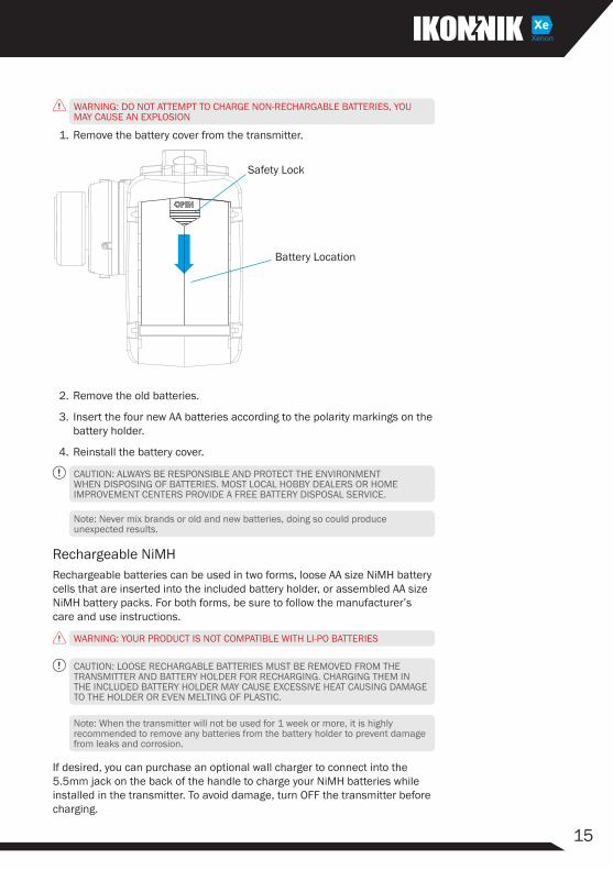
1. Remove the battery cover from the transmitter.
2. Remove the old batteries.
3. Insert the four new AA batteries according to the polarity markings on the battery holder.
4. Reinstall the battery cover.
CAUTION: ALWAYS BE RESPONSIBLE AND PROTECT THE ENVIRONMENT WHEN DISPOSING OF BATTERIES. MOST LOCAL HOBBY DEALERS OR HOME IMPROVEMENT CENTERS PROVIDE A FREE BATTERY DISPOSAL SERVICE.
Note: Never mix brands or old and new batteries, doing so could produce unexpected results.
Rechargeable NiMHRechargeable batteries can be used in two forms, loose AA size NiMH battery cells that are inserted into the included battery holder, or assembled AA size NiMH battery packs. For both forms, be sure to follow the manufacturer’s care and use instructions.
WARNING: YOUR PRODUCT IS NOT COMPATIBLE WITH LI-PO BATTERIES
CAUTION: LOOSE RECHARGABLE BATTERIES MUST BE REMOVED FROM THE TRANSMITTER AND BATTERY HOLDER FOR RECHARGING. CHARGING THEM IN THE INCLUDED BATTERY HOLDER MAY CAUSE EXCESSIVE HEAT CAUSING DAMAGE TO THE HOLDER OR EVEN MELTING OF PLASTIC.
Note: When the transmitter will not be used for 1 week or more, it is highly recommended to remove any batteries from the battery holder to prevent damage from leaks and corrosion.
If desired, you can purchase an optional wall charger to connect into the 5.5mm jack on the back of the handle to charge your NiMH batteries while installed in the transmitter. To avoid damage, turn OFF the transmitter before charging.
Safety Lock
Battery Location
16
.2.4GHz Radio System
Forward
Calibrating ESCsWhen calibrating your ESC and transmitter, ensure your Throttle Trim is centered and your Throttle and Brake EPA settings are set to their maximum of 100%. This will ensure your ESC reaches full throttle/brake when your trigger reaches full travel.
Standard OperationBelow is a brief introduction into the basic operation of your transmitter as it pertains to operating your vehicle.
Tip: When learning how to operate a radio controlled vehicle, we highly recommend you use the beginner mode feature of your transmitter. This will help reduce the risk of damage caused by a phenomenon experienced users refer to as a “panic rev”.
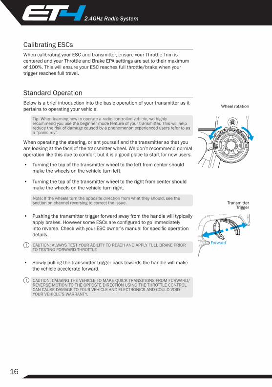
When operating the steering, orient yourself and the transmitter so that you are looking at the face of the transmitter wheel. We don’t recommend normal operation like this due to comfort but it is a good place to start for new users.
• Turning the top of the transmitter wheel to the left from center should make the wheels on the vehicle turn left.
• Turning the top of the transmitter wheel to the right from center should make the wheels on the vehicle turn right.
Note: If the wheels turn the opposite direction from what they should, see the section on channel reversing to correct the issue.
• Pushing the transmitter trigger forward away from the handle will typically apply brakes. However some ESCs are configured to go immediately into reverse. Check with your ESC owner’s manual for specific operation details.
CAUTION: ALWAYS TEST YOUR ABILITY TO REACH AND APPLY FULL BRAKE PRIOR TO TESTING FORWARD THROTTLE
• Slowly pulling the transmitter trigger back towards the handle will make the vehicle accelerate forward.
CAUTION: CAUSING THE VEHICLE TO MAKE QUICK TRANSITIONS FROM FORWARD/REVERSE MOTION TO THE OPPOSTE DIRECTION USING THE THROTTLE CONTROL CAN CAUSE DAMAGE TO YOUR VEHICLE AND ELECTRONICS AND COULD VOID YOUR VEHICLE’S WARRANTY.
Transmitter Trigger
Wheel rotation
17
Using Your Transmitter For The First TimeWARNING: PERFORM THESE STEPS IN A SAFE ENVIRONMENT! MANY FIRST TIME USERS THINK THE STREET IS A GOOD PLACE TO TEST OPERATION, HOWEVER THIS IS DANGEROUS! WE RECOMMEND USING AN OPEN FIELD OR CLOSED AREA WITHOUT VEHICLE TRAFFIC
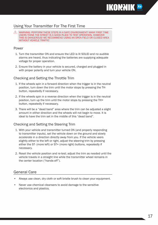
Power1. Turn the transmitter ON and ensure the LED is lit SOLID and no audible
alarms are heard, thus indicating the batteries are supplying adequate voltage for proper operation.
2. Ensure the battery in your vehicle is secured, charged and plugged in with proper polarity and turn your vehicle ON.
Checking and Setting the Throttle Trim1. If the wheels spin in a forward direction when the trigger is in the neutral
position, turn down the trim until the motor stops by pressing the TH- button, repeatedly if necessary.
2. If the wheels spin in a reverse direction when the trigger is in the neutral position, turn up the trim until the motor stops by pressing the TH+ button, repeatedly if necessary.
3. There will be a “dead band” area where the trim can be adjusted a slight amount in either direction and the wheels will not begin to move. It is ideal to have the trim set in the middle of this “dead band”.
Checking and Setting the Steering Trim1. With your vehicle and transmitter turned ON (and properly responding
to transmitter inputs), set the vehicle down on the ground and slowly accelerate in a direction directly away from you. If the vehicle veers slightly either to the left or right, adjust the steering trim by pressing either the ST- (more left) or ST+ (more right) buttons, repeatedly if necessary.
2. Reset the vehicle position and re-test; adjust the trim as needed until the vehicle travels in a straight line while the transmitter wheel remains in the center location (“hands-off”).
General Care• Always use clean, dry cloth or soft bristle brush to clean your equipment.
• Never use chemical cleansers to avoid damage to the sensitive electronics and plastics.
18
.2.4GHz Radio System
MaintenanceWe want you to enjoy your product to its fullest potential. For this to happen it is important to keep your product clean and properly maintained. Lack of cleaning and maintenance can cause component failure. For best and continued performance from your product it is recommended to briefly inspect your product for damage every few uses. Typically, a good time to do this is when changing the battery in your vehicle or while it is charging. If a problem is discovered, stop use immediately and perform repairs or seek assistance. Continued use of failed components can cause more unnecessary damage to your product.
Transmitter• Although the receiver included with your radio system is rated for all
weather use, the transmitter is not. The transmitter should not be used in the rain or other wet environment to avoid damage to the sensitive electronics.
• Clean dirt and debris off of your transmitter regularly to avoid the consequences of these getting into the sensitive electronics where they can cause short circuits and/or restrict motion of the internal steering and throttle mechanisms.
• Ensure the antenna is kept in proper working order. The transmitter is not safe to use with a broken or missing antenna.
ReceiverAlthough the receiver included with your radio system is rated for all weather use, it is recommended that you avoid submersion of the receiver, however running in puddles, rain, and snow is okay.
CAUTION: ALTHOUGH THE ELECTRONICS ARE PROTECTED FROM THE WEATHER, THE CONNECTIONS ARE NOT. ELECTRICAL CONNECTIONS WILL CORRODE WHEN EXPOSED TO MOISTURE WHEN IN USE AND IF LEFT IN A WET CONDITION. IT IS CRITICAL THAT YOU UNPLUG AND DRY ALL EXPOSED ELECTRICAL CONNECTIONS AFTER EACH USE IN WET CONDITIONS TO AVOID DAMAGE TO YOUR EQUIPMENT.
• Inspect any exposed antenna for cuts or abrasions.
• Ensure there are no kinks in the antenna or antenna tube.
• Never fold the end of the antenna over the tube, this will reduce the range and damage the antenna.
• Ensure the antenna is not being pinched by the set screw that holds the antenna tube in place.
19
Storage and Disposal
Storage• Always store all equipment in a cool dry place when not in use.
• Always disconnect the batteries before storage.
• Never store the transmitter or receiver in direct sunlight for extended periods of time.
• Never store the transmitter with batteries installed for extended periods of time. Doing so may allow the batteries to leak and cause permanent damage to the transmitter.
• Always disconnect electrical connections after use in wet environments. Allowing the contacts to dry will reduce corrosion.
DisposalYour product is considered electronic waste and should never be discarded in standard garbage containers. Please visit your local hobby dealer (and some home improvement centers) and use the FREE battery disposal center for proper disposal/recycling. Consult your local city hall for information on recycling other electronic waste.
Troubleshooting ProblemsBefore contacting customer support, recall that this is a hobby grade product intended to be user serviceable. Please take the time to fully inspect your product for any obvious causes to the issues you are experiencing. Below are some of the most common issues experienced. Scan the QR code to the right with your smart phone for quick access to the product support content on our website.
• Many control issues can be resolved by simply re-pairing the transmitter and receiver, always start here.
• Dead transmitter or vehicle batteries will cause the product to malfunction and not work properly. As with TV remote controls in your home, if the batteries are dead, they don’t work. Start power related troubleshooting with fresh batteries in the transmitter and recharged batteries in the vehicle.
• Power connections between the Battery, ESC and receiver are critical to the performance of the product. Running in various debris may cause foreign objects to snag on wires, causing connections to come loose. It is a good idea to unplug and reconnect motor and battery connections when beginning power related troubleshooting. Also inspect for any damage caused to the antenna.
20
.2.4GHz Radio System
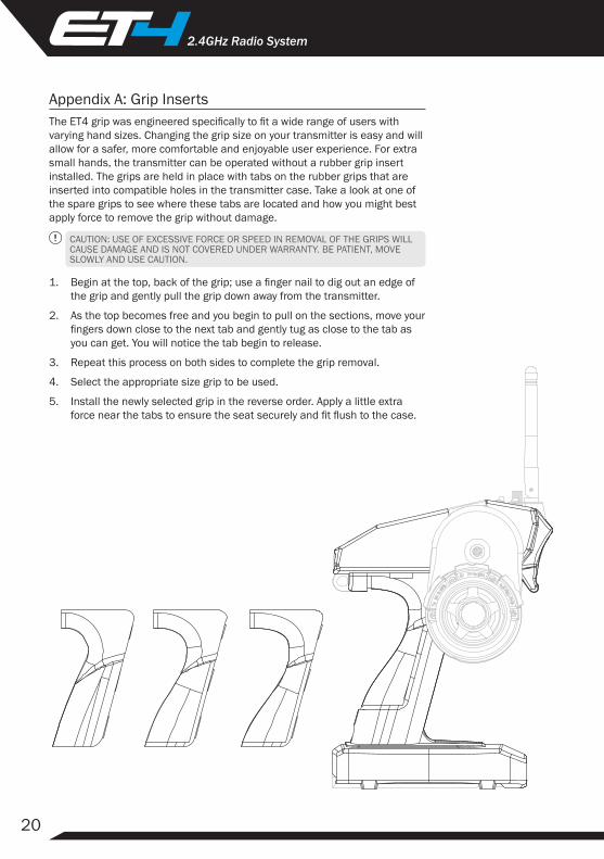
Appendix A: Grip InsertsThe ET4 grip was engineered specifically to fit a wide range of users with varying hand sizes. Changing the grip size on your transmitter is easy and will allow for a safer, more comfortable and enjoyable user experience. For extra small hands, the transmitter can be operated without a rubber grip insert installed. The grips are held in place with tabs on the rubber grips that are inserted into compatible holes in the transmitter case. Take a look at one of the spare grips to see where these tabs are located and how you might best apply force to remove the grip without damage.
CAUTION: USE OF EXCESSIVE FORCE OR SPEED IN REMOVAL OF THE GRIPS WILL CAUSE DAMAGE AND IS NOT COVERED UNDER WARRANTY. BE PATIENT, MOVE SLOWLY AND USE CAUTION.
1. Begin at the top, back of the grip; use a finger nail to dig out an edge of
the grip and gently pull the grip down away from the transmitter.
2. As the top becomes free and you begin to pull on the sections, move your fingers down close to the next tab and gently tug as close to the tab as you can get. You will notice the tab begin to release.
3. Repeat this process on both sides to complete the grip removal.
4. Select the appropriate size grip to be used.
5. Install the newly selected grip in the reverse order. Apply a little extra force near the tabs to ensure the seat securely and fit flush to the case.
21
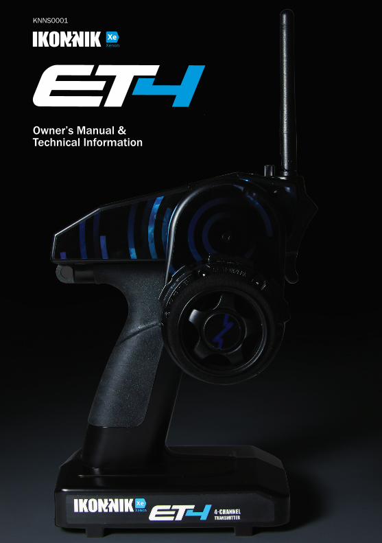
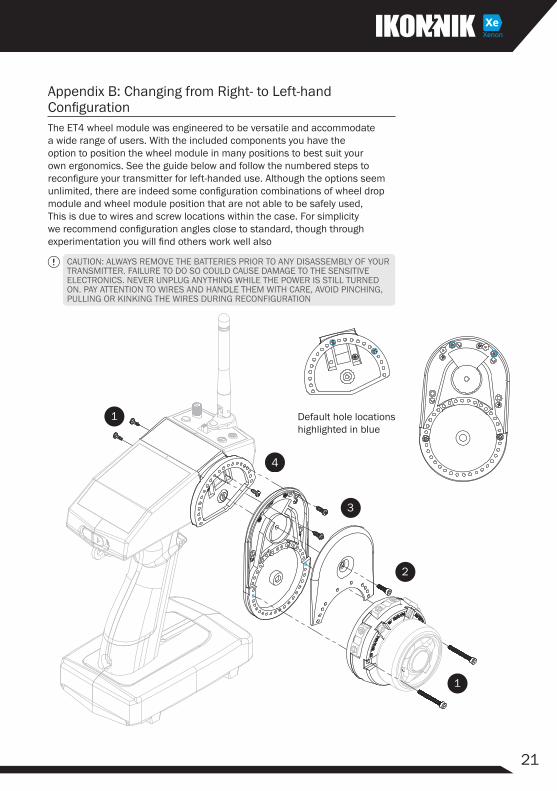
Appendix B: Changing from Right- to Left-hand ConfigurationThe ET4 wheel module was engineered to be versatile and accommodate a wide range of users. With the included components you have the option to position the wheel module in many positions to best suit your own ergonomics. See the guide below and follow the numbered steps to reconfigure your transmitter for left-handed use. Although the options seem unlimited, there are indeed some configuration combinations of wheel drop module and wheel module position that are not able to be safely used, This is due to wires and screw locations within the case. For simplicity we recommend configuration angles close to standard, though through experimentation you will find others work well also
CAUTION: ALWAYS REMOVE THE BATTERIES PRIOR TO ANY DISASSEMBLY OF YOUR TRANSMITTER. FAILURE TO DO SO COULD CAUSE DAMAGE TO THE SENSITIVE ELECTRONICS. NEVER UNPLUG ANYTHING WHILE THE POWER IS STILL TURNED ON. PAY ATTENTION TO WIRES AND HANDLE THEM WITH CARE, AVOID PINCHING, PULLING OR KINKING THE WIRES DURING RECONFIGURATION
Default hole locations highlighted in blue
22
.2.4GHz Radio System
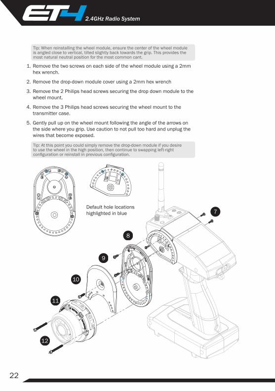
Tip: When reinstalling the wheel module, ensure the center of the wheel module is angled close to vertical, tilted slightly back towards the grip. This provides the most natural neutral position for the most common cant.
1. Remove the two screws on each side of the wheel module using a 2mm hex wrench.
2. Remove the drop-down module cover using a 2mm hex wrench
3. Remove the 2 Philips head screws securing the drop down module to the wheel mount.
4. Remove the 3 Philips head screws securing the wheel mount to the transmitter case.
5. Gently pull up on the wheel mount following the angle of the arrows on the side where you grip. Use caution to not pull too hard and unplug the wires that become exposed.
Tip: At this point you could simply remove the drop-down module if you desire to use the wheel in the high position, then continue to swapping left-right configuration or reinstall in previous configuration.
Default hole locations highlighted in blue
23
6. Rotate the wheel mount 180 degrees and reinstall without pinching wires.
7. Position the drop down module onto the mount at the desired angle and align 2-3 screw holes. Verify there will be a vertical position available for the wheel module when installed and install the Philips head screws.
8. Reinstall the 3 Philips head screws used to attach the wheel mount to the transmitter case (only 1 hole should be exposed through the drop down module, this is okay).
9. Position wires in grooves of drop down module (if used) and push any excess back inside the wheel mount. The wires should only be long enough to reach the mounting location of the wheel module.
10. Reinstall the drop down module cover using caution to not pinch the wires.
11. Position the wheel module in place with vertical orientation properly set.
12. Reinstall 2 wheel module screws.
Appendix C: Spare Parts List KNNS0001 .......ET4 4Ch 2.4GHz Xenon (Xe) AW Radio System
KNNS0002 .......ET4 4Ch 2.4GHz Xenon (Xe) Transmitter
KNNS0008 .......4Ch 2.4GHz Xenon (Xe) Receiver, AW
KNNS0012 .......Battery Holder, 4xAA
KNNS0013 .......ET4 Grips, S-M-L
KNNS0014 .......ET4 Model Decal Set
KNNS0015 .......Wall Charger
KNNS0016 .......ET4 Quick Start Guide
KNNS0017 .......ET4 Owner’s Manual
24
.2.4GHz Radio System
US Warranty Information30 Day Limited Warranty
General Disclaimer: This item is to be free of manufacture defects at time of purchase. This warranty does not cover breakage due to abuse, improper break-in, improper setup, or improper operation.
We at IKONNIK RC have made every effort in component design, material selection and assembly to make our products as durable as possible. IKONNIK products are covered under warranty only against manufacturer’s defect in materials, workmanship or assembly when it is new (before being used).
If you believe a defect in materials, workmanship or assembly was not apparent when the product was new and only became evident after the product was used, then please contact your local HobbyTown® to apply for warranty service. You must provide your original sales receipt verifying the proof-of purchase and date thereof.
Provided warranty conditions have been met, the components that are found to be defective, incorrectly made, or incorrectly assembled within the warranty coverage time period may be repaired or replaced under the sole discretion of HobbyTown®. In the event that your product needs a repair or a replacement part that is not covered by this warranty, your local HobbyTown® dealer can assist you with obtaining the genuine replacement parts and/or accessories to service your IKONNIK product.
If you purchased your IKONNIK product from a HobbyTown® internet site not affiliated with a local store, please consult that site for its service policies.
Distributed in the US by:
Firelands Customer Service/Product Support 1133 Libra Drive, Lincoln, NE 68512www.firelandsgroup.com
1-800-205-6773 [email protected]

25

www.IKONNIK-RC.com000554-002 (REV A)
Scan this QR code with your smartphone for more information on the IKONNIK ET4.