Embed Size (px)
Citation preview

1
Owners Manual
TAEGE ENGINEERING
LIMITED (www.taege.com)
Trailing Direct Seed Drills
Series 300 and 360
Specializing in the Design and Manufacture of Innovative Farm Equipment
Manufactured by: Dealer / Local Agent :
Taege Engineering Ltd Main West Road,
Sheffield 7500 New Zealand
Ph: 64 3 318 3824
Fax: 64 3 318 3646
E-mail: [email protected]
www.taege.com
2
Contents
Page
Contents 2
Introduction 3
Safety 4
Safety Maintenance Storage 5
Warranty 6
Removing the End Tow 7
Getting the Drill ready for the first time 7
Understanding Calibration 7
Calibration 7
Drilling Speed 8
Setting the Sowing Depth 8
Drill Operation 8
End of Day 8
Removing the Sponge Bar Assemblies 8
Fitting the Sponge Bar Assemblies 9
Bolted Connections 9
Hydraulic System 9
Setting the Flow Divider (equalizer valve) 9
Tyre Pressure 9
Lubrication 10
Wheel Scrapers 10
Jack Stand 10
Daily Maintenance 10
Notes 11
Warranty Certificate 12
3
Introduction
This manual sets out the technical information for your guidance in the proper
use and servicing of this implement.
Extra copies can be downloaded from www.taege.com.
The serial/chassis number are stamped and/or plated on the front right hand side
of the drill, on the main chassis cross member.
Reference to the right and left hand side of the drill is as you see it from
behind the drill looking toward the tractor.
Be sure to quote the drill model, chassis number and Controller version number
when seeking advice and/or ordering spare parts.
E.g. series 300 S/No 535 36 11. RC300L ver 2.52d
Thank you for buying a TAEGE Seed Drill, we pride ourselves with over 50 years
of specializing in the design and manufacture of innovative farm machinery.
Your seed drill has been carefully designed and manufactured to provide years of
dependable service, given normal care and proper operation.
4
Safety
Focus on being prepared for emergencies.
Read the operators manual carefully. Always follow recommended safe practices for operating this drill and its
associated equipment.
Including tractors and other machinery used in conjunction with this drill
Identify and avoid un-safe terrain.
Always use lynch pins and safety chains on all drawbar pins.
Do not exceed 30km/hr while towing the drill in normal working position.
Keep all covers in place at all time unless removed for repairs or servicing.
Stop the drill before making adjustments.
Lower drill to ground or put on stands when working around or under the
machine.
Ensure tractor electrics are disconnected and/or turned off and machine
hydraulics disconnected when working on drill. Tighten all nuts and bolts after initial use and thereafter at regular 30 hr
intervals.
Tractor hydraulics should not be operated in the float position to ensure full
drill penetration and proper contour following.
Put the safety lockout stays (spacers) on the wheel rams so they are locked
in the fully extended position while transporting.
Watch for moving parts and stay well clear of drill while it is moving.
Practice safe handling of agricultural chemicals including treated seed.
Double safety chains should be used to secure drills both on end tow, and
behind the tractor.
End-tow units with mudguards and lights for road use are available as an
optional extra.(see Removing the end tow kit)
Wear appropriate safety equipment while operating the drill and including when filling seed / fertilizer hoppers and/or adjusting drill.
This includes safety glasses, gloves, ear protection, close fitting clothing
and steel capped boots.
Visit www.osh.dol.govt.nz for additional guidance and instruction on safe
practices in the rural sector and/or other sectors targeted for the intended
use of this drill.
5
SAFE OPERATING PROCEDURES FOR
TAEGE DRILLS Before operating the Taege Drill please read the following ‘Safe Operating
Procedures’. Failure to comply with these warnings could result in serious injury. A careful and alert operator is the best insurance against incidents. Taege drills are designed to be safe to operate.
Do not wear loose clothing, unrestrained long hair, jewellery or anything which could entangle in components or limit your vision.
Never work or walk or allow any person/child under the equipment.
If travelling on the road please ensure that the tractor being used is fitted with the necessary lights, turn signals and all other legally required equipment.
No person is ever to be between the tractor and this implement.
No person/child is to climb or ride onto this implement at any time other than the operator.
When parking or before working on the machine. Stop the tractor on a firm level surface and apply the parking brake. Lower the machine to the ground and switch off the engine. Remove the key for added safety.
The drill /machine should not to be used unless the operator has been trained in its safe use.
MAINTENANCE Daily
Grease all grease points Weekly
Check the tyne nuts and wheel nuts are tight at all times
Check hitch points for wear. Replace when necessary.
Replace tynes if bent only by those recommended by the manufacturer.
STORAGE
Store in shed away from vehicle or pedestrian traffic.
Ensure machine is empty to eliminate rodent damage to rollers as this is not covered by warranty.
6
Warranty
From the date of purchase your TAEGE machine is covered by a 12-month
warranty period for faulty parts and/or workmanship.
Ensure your dealer completes and returns a warranty certificate within 7 days of
date of purchase
Send to
Taege Engineering Ltd
Main West Road
Sheffield 7500
New Zealand.
On delivery record the following Basic Information
Model:…………………………………………………………………………………………………….
Chassis Number:…………………………………………………………………………………….
Delivery Date:…………………………………………………………………………………………
Owner: Dealer:……………………………………………………………………………………….
Check for shipping damage. In cases of shipping damage, ask dealer to arrange
for appropriate claim to be lodged immediately.
Ensure the attached registration / warranty validation card has been completed.
Place owners copy of warranty in safe place.
Check that the Dealers copy of the warranty has been correctly filled out and
returned to the manufacturer
Contact your dealer if you have any further queries.
Disclaimer Drilling with Taege® seed drills in conditions normally outside of the germination
tolerances of the seed concerned cannot be expected to give satisfactory results.
Every attempt has been made to ensure the correctness of information and
diagrams in this manual. Consequently, Taege Engineering Ltd will not be
responsible for any damage or consequential loss arising out of misinterpretation
of, or failure to follow, recommended practices and procedures. Nor will Taege
Engineering Ltd be liable for any damage caused by, or arising out of
modification or misuse of its product. Taege Engineering Ltd reserves the right to
change technical details and prices without prior notice.
A full copy of Taege Engineering Ltd warranty document is available from
[email protected] upon request.
7
Removing the End Tow 1. Position the jack stand to support the drill.
2. Unhitch the drill from the towing vehicle.
3. Lower the drill drawbar to allow connection to the tractor drawbar and
connect the drawbar turnbuckle.
4. Connect to the tractor drawbar and then connect the hydraulic hoses.
5. Remove the end tow drawbar from the drill. 6. Raise the drill to its highest position to allow the end tow wheels to be
removed by firstly removing the locating pins and sliding the transport
wheels outwards from there mountings.
7. Remove the end toe drawbar mounting clamps.
8. Change the tine harrows into the working position.
Getting the Drill ready the first time Attach the tractor to the drill drawbar using the tractor drawbar pin. Connect the
hydraulic hoses and plug in the drill power lead to the tractor 30amp auxiliary
power supply. Lower the jack and stow in the transport position. Unscrew the
hydraulic transport screw on the drill equalizer valve and lower the drill so that
the tynes are on the ground. You are now ready to put seed/fertilizer into the
hopper/s. Ensure that the hydraulic hoses and wiring loom are clear of the tractor linkage and drawbar.
Understanding Calibration Calibration is the method on which you depend to put the correct amount of seed
or fertilizer on an area of seed bed. The Controller control has been programmed to know the sowing width of the drill, the number of wheel counts per one
hundred metres, and has the ability to speed up and slow down according to the
ground speed. What the operator needs to do “is to accurately measure by
weight of the seed that is to be sown”. This is done by reading and following the
instructions on page two of the Controller Manual. It most important that this
is accurate, the weighing scales that are provided should be used, these measure
in one gram increments. Care must be taken to prime the hopper before being
calibrated, making sure that no bridging occurs.
Comment:
Calibration Go to the RC300L Controller ver2.5x Operators manual and follow the instructions
Page 2 QUICK CALIBRATION
8
Drilling Speed Taege drills are able to travel at faster average speeds achieving better tilth,
average recommended speeds are from 8Kph to 12Kph.
Obviously ground conditions play an important part in achieving this optimum
speed. It is important to inspect your seed placement when determining optimum
drilling speed.
Setting the Sowing Depth
Your TAEGE drill is fitted with HD Flexible “S” tynes which contact the ground oat
a specific preset angle which gives greater contour following and penetration.
To check the sowing depth it is recommended that you travel at your optimum
drilling speed and check to make sure that seed placement is correct.
To set the depth, fit ram collars to the hydraulic rams and making sure that the same sized collars are fitted to each side of the drill.
Each collar size combination gives you 3mm adjustment.
To adjust the level of the drill, turn the drawbar turnbuckle to achieve the
optimum level.
Drill Operation Once you have set the correct depth set, mount the tractor and start drilling by
turning the Controller to RUN. When you lift the drill at the end of a drilling run,
the drill will automatically stop sowing seed and then start when the drill is
lowered.
End of Day Follow the instructions on the page ‘Run to Empty’ in the RC300L Controller
ver2.5x Operators manual.
Removing Sponge Bar Assemblies Lift the flaps on either side of the seed/fertilizer hoppers and secure them in the
raised position using the locking tabs mounted on either side of hoppers in the
centre. Push down the Taege Snap locks and remove the sponge bars by putting
sideways pressure on the bar (away from the motor) until it clears the drive
shaft. Repeat the procedure for the other sponge bar/s.
9
Fitting the Sponge bar Assemblies
Locate the plain end of the sponge bar within the spring-loaded bearing on the
side of the drill under the seed/fertilizer hoppers applying sufficient even
pressure along the bar. Depress the spring in the bearing block so the collar on
the motor end of the roller bar clears the end of the slotted driven shaft on the
other end of the drill. Release the pressure on the bar, allowing the collar to
engage with the drive shaft. Rotate the sponge bar assembly until the roll pin
locates in the slot on the drive shaft. In this position all the sponges should be in
line with the hopper openings. Check that all sponges are secure on the shaft. Always fit the furthest away sponge bar first and make sure that the sponge bar
located correctly at both ends. They should align with the hopper openings. When
the second bar is fitted, align the sponges with each other. If adjustment is
needed, loosen with a 3mm allen key and align making sure both sponge bars
are fully engaged with the motor end drive.
Bolted Connections All bolts and grub screws should be re-tightened after the first day or 10 ha of
use. Thereafter the tyne and tip bolts should checked at regular intervals (i.e.
every 50 to 100 ha). Nyloc nuts should be replaced or a spring washer added
after they have been removed more than once.
Hydraulic System Your Taege Drill is fitted with a double acting hydraulic system and flow divider.
The tractor hydraulics must be operated without using the float option for
optimum ground penetration and contour following to ensure that the driving
ground wheel remains in contact with the ground at all times.
Later drills have phasing rams.(No flow divider.)
Setting the Flow Divider (equalizer valve)
Connect both hose to the tractor hydraulics. Unscrew the lockout tap on the flow
divider. Raise the drill to its highest position. If the drill is uneven, unscrew the
flow divider setting valve 3x turns, raise and lower the hydraulics two or three
times and then with the hydraulics in its raised position, screw in the flow divider
setting valve screw. Raise and lower the drill several times to ensure that the
system is operating correctly. Then adjust the tractor flow control for speed.
Tyre Pressure The recommended tyre pressure is 26 -28.5Kpa (18-20psi) for the land wheels.
The drill will bounce excessively if the land wheel tyres are over inflated.
10
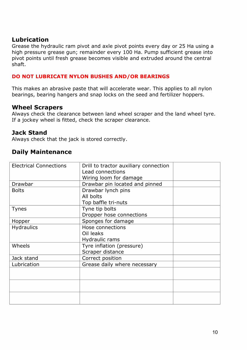
Lubrication Grease the hydraulic ram pivot and axle pivot points every day or 25 Ha using a
high pressure grease gun; remainder every 100 Ha. Pump sufficient grease into
pivot points until fresh grease becomes visible and extruded around the central
shaft.
DO NOT LUBRICATE NYLON BUSHES AND/OR BEARINGS
This makes an abrasive paste that will accelerate wear. This applies to all nylon
bearings, bearing hangers and snap locks on the seed and fertilizer hoppers.
Wheel Scrapers
Always check the clearance between land wheel scraper and the land wheel tyre.
If a jockey wheel is fitted, check the scraper clearance.
Jack Stand Always check that the jack is stored correctly.
Daily Maintenance Electrical Connections Drill to tractor auxiliary connection
Lead connections Wiring loom for damage
Drawbar Drawbar pin located and pinned
Bolts Drawbar lynch pins
All bolts
Top baffle tri-nuts
Tynes Tyne tip bolts Dropper hose connections
Hopper Sponges for damage
Hydraulics Hose connections
Oil leaks
Hydraulic rams
Wheels Tyre inflation (pressure) Scraper distance
Jack stand Correct position
Lubrication Grease daily where necessary

11
NOTES
12
Warranty Certificate
From the date of purchase your TAEGE machine is covered by a 12-month
warranty period for faulty parts and/or workmanship.
Ensure your dealer completes and returns a warranty certificate within 7 days of
date of purchase.
Send to
Taege Engineering Ltd Dealer Name and Address
Main West Road
Sheffield 7500
New Zealand.
On delivery record the following Basic Information
Model:…………………………………………………………………………………………………….
Chassis Number:…………………………………………………………………………………….
Delivery Date:…………………………………………………………………………………………
Owner: Dealer:……………………………………………………………………………………….
Check for shipping damage. In cases of shipping damage, ask dealer to arrange
for appropriate claim to be lodged immediately.
Ensure the attached registration / warranty validation card has been completed.
Place owners copy of warranty in safe place.
Check that the Dealers copy of the warranty has been correctly filled out and
returned to the manufacturer
Contact your dealer if you have any further queries.
Disclaimer Drilling with Taege® seed drills in conditions normally outside of the germination
tolerances of the seed concerned cannot be expected to give satisfactory results.
Every attempt has been made to ensure the correctness of information and
diagrams in this manual. Consequently, Taege Engineering Ltd will not be
responsible for any damage or consequential loss arising out of misinterpretation
of, or failure to follow, recommended practices and procedures. Nor will Taege
Engineering Ltd be liable for any damage caused by, or arising out of
modification or misuse of its product. Taege Engineering Ltd reserves the right to
change technical details and prices without prior notice.
A full copy of Taege Engineering Ltd warranty document is available from
[email protected] upon request.