Embed Size (px)
Citation preview
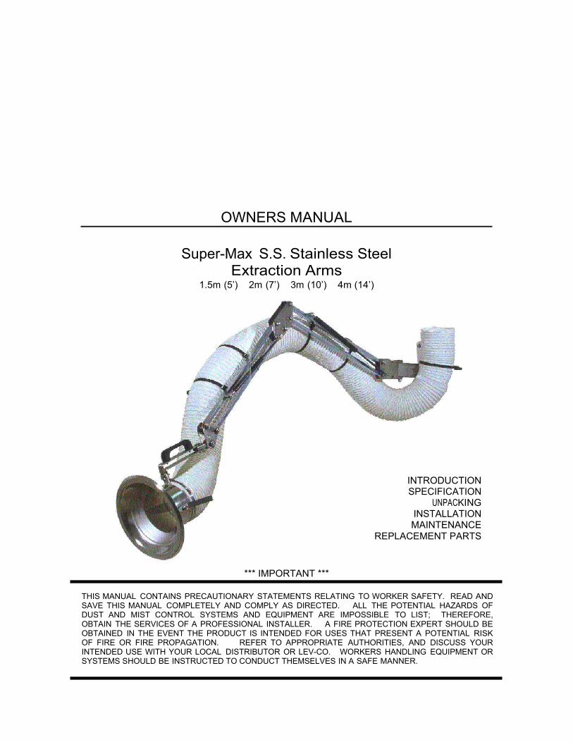
OWNERS MANUAL
Super-Max S.S. Stainless Steel Extraction Arms
1.5m (5’) 2m (7’) 3m (10’) 4m (14’)
INTRODUCTION SPECIFICATION
UNPACKING INSTALLATION
MAINTENANCE REPLACEMENT PARTS
*** IMPORTANT ***
THIS MANUAL CONTAINS PRECAUTIONARY STATEMENTS RELATING TO WORKER SAFETY. READ AND SAVE THIS MANUAL COMPLETELY AND COMPLY AS DIRECTED. ALL THE POTENTIAL HAZARDS OF DUST AND MIST CONTROL SYSTEMS AND EQUIPMENT ARE IMPOSSIBLE TO LIST; THEREFORE, OBTAIN THE SERVICES OF A PROFESSIONAL INSTALLER. A FIRE PROTECTION EXPERT SHOULD BE OBTAINED IN THE EVENT THE PRODUCT IS INTENDED FOR USES THAT PRESENT A POTENTIAL RISK OF FIRE OR FIRE PROPAGATION. REFER TO APPROPRIATE AUTHORITIES, AND DISCUSS YOUR INTENDED USE WITH YOUR LOCAL DISTRIBUTOR OR LEV-CO. WORKERS HANDLING EQUIPMENT OR SYSTEMS SHOULD BE INSTRUCTED TO CONDUCT THEMSELVES IN A SAFE MANNER.

ALWAYS USE LEV-CO REPLACEMENT PARTS AND FILTERS TO MAINTAIN WARRANTY.
TO ORDER SPARE PARTS: CONTACT YOUR LOCAL REPRESENTATIVE, OR
The Local Exhaust & Ventilation Company 1050 Brock Road, Unit 22-24
Pickering, Ontario CANADA L1W 3X4
Phone (905) 831-7001 FAX (905) 831-7443
E-MAIL: [email protected]
INTERNET: http://www.lev-co.com
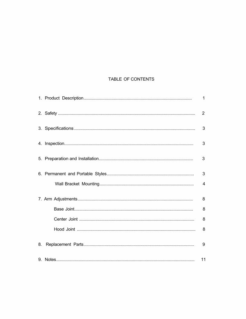
TABLE OF CONTENTS 1. Product Description............................................................................................. 1
2. Safety ...................................................................................................................... 2
3. Specifications ........................................................................................................ 3
4. Inspection............................................................................................................... 3
5. Preparation and Installation................................................................................. 3
6. Permanent and Portable Styles........................................................................... 3
Wall Bracket Mounting................................................................................. 4
7. Arm Adjustments................................................................................................... 8
Base Joint...................................................................................................... 8
Center Joint ................................................................................................... 8
Hood Joint ...................................................................................................... 8
8. Replacement Parts............................................................................................... 9
9. Notes....................................................................................................................... 11
1
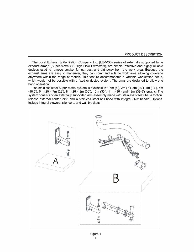
PRODUCT DESCRIPTION
The Local Exhaust & Ventilation Company Inc. (LEV-CO) series of externally supported fume
exhaust arms,* (Super-Max© SS High Flow Extractors), are simple, effective and highly reliable devices used to remove smoke, fumes, dust and dirt away from the work area. Because the exhaust arms are easy to maneuver, they can command a large work area allowing coverage anywhere within the range of motion. This feature accommodates a variable workstation setup, which would not be possible with a fixed or ducted system. The arms are designed to allow one hand operation.
The stainless steel Super-Max© system is available in 1.5m (5’), 2m (7’), 3m (10’), 4m (14’), 5m (16.5’), 6m (20‘), 7m (23‘), 8m (26‘), 9m (30‘), 10m (33‘), 11m (36’) and 12m (39.5’) lengths. The system consists of an externally supported arm assembly made with stainless steel tube, a friction release external center joint, and a stainless steel bell hood with integral 360 handle. Options include integral blowers, silencers, and wall brackets.
Figure 1
2
READ THIS MANUAL CAREFULLY BEFORE INSTALLING OR USING YOUR EXTERNAL FUME EXHAUST ARM. RETAIN THESE INSTRUCTIONS FOR FUTURE REFERENCE.
SAFETY RULES
Follow all electrical and safety codes as well as the National Electrical Code (NEC), National
Fire Protection Association (NFPA), and the Occupational Safety and Health Act (OSHA). All electrical connections and wiring should be performed by qualified personnel only.
National Fire Protection Association (NFPA) standards require specific duct design and dust collector configuration when collecting potentially reactive metal dusts, such as aluminum and magnesium, and other materials. NFPA also covers other dusts such as grain, plastics, etc. A guideline for determining the precautions to be taken can be found in NFPA 497. Other NFPA standards may apply to your specific application. Consult current NFPA standards, available from NFPA, 1 Batterymarch Park, Quincy, MA, 02269, 1-800-344-3555, for applicable safeguards which may be required for the Installation, Operation, and Service of this product. Fire suppression equipment provided by others.
Additional references are the Uniform Building Code and Uniform Mechanical Code.
WARNING
1. Avoid mixing combustible materials such as (but not limited to) buffing lint, paper/wood dust,
aluminum and magnesium with dust generated from the grinding of ferrous metals. This creates a potential for fire due to the mixing of sparks and combustible materials.
2. Under no conditions should the machine operator be allowed to put lit cigarettes or any
burning object into this or any dust/mist control system. 3. Installation of this unit in applications where the chance for heated and/or flammable
materials to enter the unit should be evaluated to determine if a fire protection/extinguishing system should be installed. Such a system may be required by Federal, State, or Local codes, or as required by organizations as NFPA and Factory Mutual Insurance or your insurance carrier. LEV-CO can offer basic guidelines for such an installation, however final installation design is the responsibility of the filtration unit Owner/User.
4. When exhaust arms are attached to a collector with hazard location requirements, explosion
relief vents are required on some applications. Consult with an insurance underwriter or an NFPA manual to determine proper vent size ratio. Dust or mist collectors must be located outdoors unless otherwise indicated by NFPA standards. Dust and mist collectors DO NOT CONTAIN EXPLOSION RELIEF VENTS as shipped from the factory and must be field installed per NFPA standards.
5. Disconnect all power before installing or serving this equipment.

3
SPECIFICATIONS(*): EXTERNAL ARM
CONSTRUCTION: Rigid stainless steel tubes, flexible hose, 4-6 friction release external joints, swivel base joint/seal, and a high efficiency stainless steel bell hood with integral 360 handle.
*LEV-CO has a policy of continuous research and improvement, and reserves the right to change design and specifications without notice.
INSPECTION AND UNPACKING
Inspect your LEV-CO unit for shipping damage immediately upon receipt. Damaged carton(s),
broken crate(s), etc. are indications that the unit may have been damaged in shipment. It is also possible shipping damage may be concealed and not noticed until the unit is installed and in operation. If any damage is found, notify your delivery carrier at once and enter a claim. Claims must be filed within 5 consecutive days of receipt of shipment. FREIGHT DAMAGE CLAIMS ARE THE RESPONSIBILITY OF THE PURCHASER, NOT LEV-CO.
PREPARATION AND INSTALLATION
All arm structures are shipped partially assembled. The arms have been pre-assembled and tested at the factory and all joints have been
adjusted. If further adjustment is required, refer to Assembly Instructions for details. Fire suppression equipment provided by others.
PERMANENT AND PORTABLE STYLES
Super-Max© SS High Flow Extractors are available in either permanent (overhead) or
portable style variants. The permanent style arm is intended for use with a LEV-CO wall mount bracket and
provides for a suspended overhead installation (see Figure 1 on page 1). The flow of exhaust air is directed upward at the base. The wall bracket allows for 300° rotation of the arm about the base and retraction above base height when stowed.
The portable style arm is intended for use on portable machinery such as the LEV-CO’s line of portable cartridge fume and dust collectors.
Care must be taken when selecting the location for a permanently mounted unit or in the use of a portable system. Do not place the device in a position where other equipment must pass, such as overhead cranes, or where the normal range of the arm may come into contact with automatic equipment or electrical devices.
4
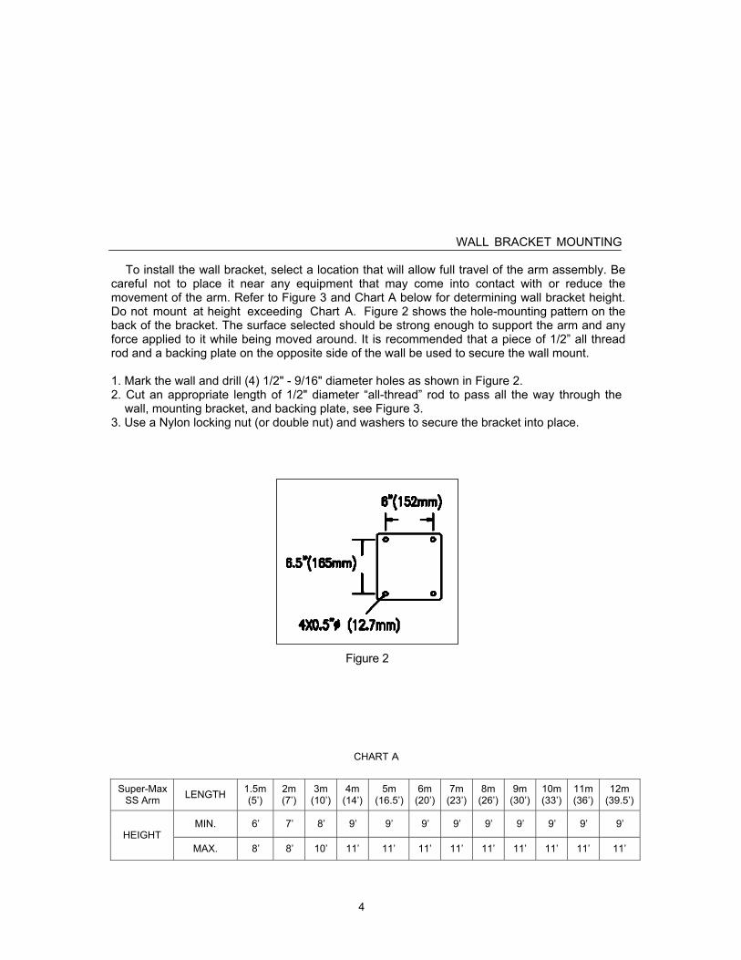
WALL BRACKET MOUNTING
To install the wall bracket, select a location that will allow full travel of the arm assembly. Be careful not to place it near any equipment that may come into contact with or reduce the movement of the arm. Refer to Figure 3 and Chart A below for determining wall bracket height. Do not mount at height exceeding Chart A. Figure 2 shows the hole-mounting pattern on the back of the bracket. The surface selected should be strong enough to support the arm and any force applied to it while being moved around. It is recommended that a piece of 1/2” all thread rod and a backing plate on the opposite side of the wall be used to secure the wall mount.
1. Mark the wall and drill (4) 1/2" - 9/16" diameter holes as shown in Figure 2. 2. Cut an appropriate length of 1/2" diameter “all-thread” rod to pass all the way through the
wall, mounting bracket, and backing plate, see Figure 3. 3. Use a Nylon locking nut (or double nut) and washers to secure the bracket into place.
Figure 2
CHART A
Super-Max SS Arm
LENGTH 1.5m
(5’) 2m (7’)
3m (10’)
4m (14’)
5m (16.5’)
6m (20’)
7m (23’)
8m (26’)
9m (30’)
10m (33’)
11m (36’)
12m (39.5’)
MIN.
6’
7’
8’
9’
9’
9’
9’
9’
9’
9’
9’
9’
HEIGHT
MAX.
8’
8’
10’
11’
11’
11’
11’
11’
11’
11’
11’
11’

5
Other 3 optional mounting style is available as shown in the picture below:
Art. Nr. Art. Nr.
ø160 mm ø200 mm
Super-Max Ceiling Extractor Arm SMT 1.5 m. Turning flange incl. P-130 P-223
Super-Max Ceiling Extractor Arm SMT 2 m. Turning flange incl. P-135 P-224
Super-Max Ceiling Extractor Arm SMT 3 m. Turning flange incl. P-136 P-225
Super-Max Ceiling Extractor Arm SMT 4 m. Turning flange incl. P-152 P-231
Super-Max Table Extractor Arm SMB 1.5 m. Turning flange incl. P-232 P-237
Super-Max Table Extractor Arm SMB 2 m. Turning flange incl. P-233 P-238
Super-Max Table Extractor Arm SMB 3 m. Turning flange incl. P-110 P-119
Super-Max Table Extractor Arm SMB 4 m. Turning flange incl. P-111 P-120
Super-Max Filter Extractor Arm SMF 1.5 m. Without turning flange. P-245 P-253
Super-Max Filter Extractor Arm SMF 2 m. Without turning flange. P-248 P-255
Super-Max Filter Extractor Arm SMF 3 m. Without turning flange. P-249 P-256
Super-Max Filter Extractor Arm SMF 4 m. Without turning flange. P-250 P-257
6
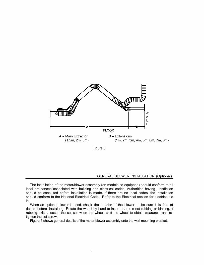
W A L L
FLOOR
A = Main Extractor B = Extensions (1.5m, 2m, 3m) (1m, 2m, 3m, 4m, 5m, 6m, 7m, 8m)
Figure 3
GENERAL BLOWER INSTALLATION (Optional)
The installation of the motor/blower assembly (on models so equipped) should conform to all
local ordinances associated with building and electrical codes. Authorities having jurisdiction should be consulted before installation is made. If there are no local codes, the installation should conform to the National Electrical Code. Refer to the Electrical section for electrical tie in.
When an optional blower is used, check the interior of the blower to be sure it is free of debris before installing. Rotate the wheel by hand to insure that it is not rubbing or binding. If rubbing exists, loosen the set screw on the wheel, shift the wheel to obtain clearance, and re- tighten the set screw.
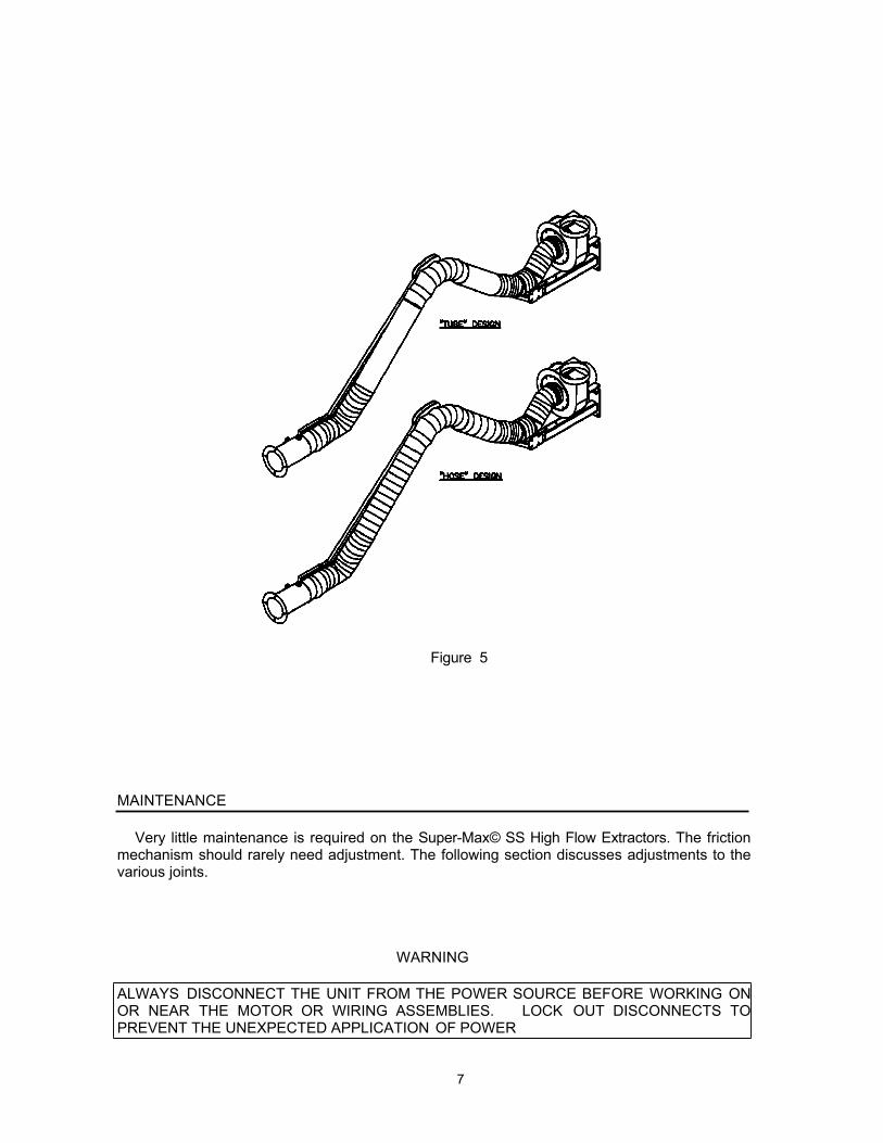
Figure 5 shows general details of the motor blower assembly onto the wall mounting bracket.
7
Figure 5
MAINTENANCE
Very little maintenance is required on the Super-Max© SS High Flow Extractors. The friction
mechanism should rarely need adjustment. The following section discusses adjustments to the various joints.
WARNING
ALWAYS DISCONNECT THE UNIT FROM THE POWER SOURCE BEFORE WORKING ON OR NEAR THE MOTOR OR WIRING ASSEMBLIES. LOCK OUT DISCONNECTS TO PREVENT THE UNEXPECTED APPLICATION OF POWER

8
ARM ADJUSTMENTS
The following section discusses the procedure required to adjust the three sections of
the Super-Max© SS High Flow Extractors.
BASE JOINT
Figure 6 Shown with optional wall bracket and blower assembly.
CENTER JOINT
To adjust the center joint, maneuver the arm to the desired working position. While holding the pivot bolt head with a wrench, tighten the Nyloc nut illustrated in Figure 7. Tighten the nut only enough to hold the arm in place. Excessive tightening will wear out the friction material prematurely.
Figure 7
Figure 8
HOOD JOINT
The hood is held in place by a swiveling U-joint. Tighten the through bolts enough so that the hood remains in the desired position, but can be easily moved. Do not over-tighten.

9
REPLACEMENT PARTS Listed below are part numbers for the Super-Max© SS High Flow Extractors. Use the following section for parts replacement.
ITEM QTY PART # WEB # DESCRIPTION
1
P-112-SS
Stainless Steel Extraction arm 1.5m (5')L with 10" wall bracket. Parallelogram
5857 design. Stainless steel hood with combined universal- and spinning-joint. Flameproof PVC hose 160mm (6.5”) Ø* with internal steel spiral. Adapted for central or individual extraction fan. Total length 1.8m (5.9').
2
P-113-SS
Stainless Steel Extraction arm 1.5m (5')L w/20" wall bracket. Parallelogram
5858 design. Stainless steel hood with combined universal- and spinning-joint. Flameproof PVC hose 160mm (6.5”) Ø* with internal steel spiral. Adapted for central or individual extraction fan. Total length 2.1m (6.6').
3
P-114-SS
Stainless Steel Extraction arm 2m (7')L with 10" wall bracket. Parallelogram
5859 design. Stainless steel hood with combined universal- and spinning-joint. Flameproof PVC hose 160mm (6.5”) Ø* with internal steel spiral. Adapted for central or individual extraction fan. Total length 2.5m (8.25').
4
P-115-SS
Stainless Steel Extraction arm 2m (7')L with 20" wall bracket. Parallelogram
5860 design. Stainless steel hood with combined universal- and spinning-joint. Flameproof PVC hose 160mm (6.5”) Ø* with internal steel spiral. Adapted for central or individual extraction fan. Total length 3m (10').
5
P-117-SS
Stainless Steel Extraction arm 3m (10')L with 20" wall bracket. Parallelogram
5861 design. Stainless steel hood with combined universal- and spinning-joint. Flameproof PVC hose 160mm (6.5”) Ø* with internal steel spiral. Adapted for central or individual extraction fan. Total length 4m (14').
6
P-121-SS
Stainless Steel Extraction arm 4m (14')L with 20" wall bracket. Parallelogram
5862 design. Stainless steel hood with combined universal- and spinning-joint. Flameproof PVC hose 160mm (6.5”) Ø* with internal steel spiral. Adapted for central or individual extraction fan. Total length 5m (16.5').
7
P-147-SS
Fan P-Max© Stainless Steel 1500 m3/h (925 ft3/m)/0,37 kW (1/2 HP, 1 Phase) 5910 made of steel sheet, powder painted. Radial impeller with curved blades. Direct
connected motor. For mounting directly to fume extractor.
8
P-148-SS Fan P-Max© Stainless Steel 2100 m3/h (1500 ft3/m)/0,75 kW (1 HP,1 Phase)
5911 made of steel sheet, powder painted. Radial impeller with curved blades. Direct connected motor. For mounting directly to fume extractor.
9
P-149-SS
Fan P-Max© Stainless Steel 3400 m3/h (2025 ft3/m)/0,75 kW (1 HP, 1 Phase) 5918 made of steel sheet, powder painted. Radial impeller with curved blades. Direct
connected motor. For mounting directly to fume extractor.
10
DCH-1-SS Stainless Steel Cartridge Collector with 1 Clean 2® cartridge filter with 150 ft2
8162 media, manual Vibra-Pulse® cleaning system 1HP 115/230/1/60 TEFC motor at 12/6 amps, 6” collar on top. Includes removable external dust tray.
11
DCH-2-SS
Stainless Steel Cartridge Collector w/2 Clean 2® cartridge filters (150 ft2 media
8163 each) manual Vibra-Pulse®. 1.5HP 115/230/1/60v, 17/8.5 amps, w/switch cord on 115 volt only, & spark resistant blower. 8”collar on top & removable external dust tray.
12 OM-004-SS 5679 Table/ceiling bracket 0.7 m (2.3’). 13 P-021-SS 8165 Stainless steel ceiling/floor stanchion 3.3m for extraction arm with wall bracket 14 P-022-SS 8166 Stainless steel ceiling/floor stanchion 6.6m for extraction arm with wall bracket
15 OM-003-SS- DEDUCT
8192 DEDUCT Wall bracket 0.5 m (1.65’). 1 hose band included.
16
H-MAX-FII- 2-SS
H-MAX Stainless Steel Boom Kit (Total length: 3m(10')) for 8" diameter Super-
8927 Max SS extraction arms. Each boom comes c/w: 1 - OM-037-SS, 2.3m Main Boom including wall bracket & 1 - OM–057-SS, arm/reel mounting bracket (0.7m) & 4m (14’) of 200mm (8”) Ø Hose.
17 S-200 6070 Silencer for P-Max series fan
18
P-014 5818 Energy Saver Automatic E-Max©. Automatic start/stop of the fan by welding. Available in 230,460V/3/60.
10
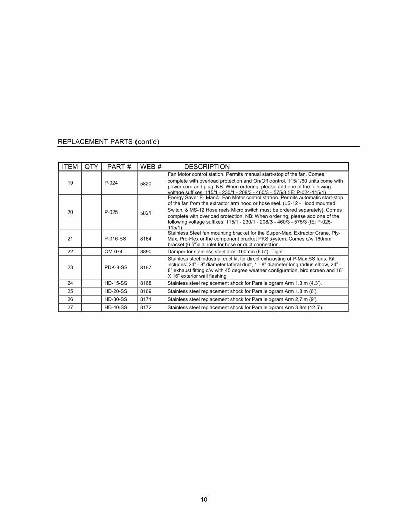
REPLACEMENT PARTS (cont'd)
ITEM QTY PART # WEB # DESCRIPTION
19
P-024
Fan Motor control station. Permits manual start-stop of the fan. Comes
5820 complete with overload protection and On/Off control. 115/1/60 units come with power cord and plug. NB: When ordering, please add one of the following voltage suffixes: 115/1 - 230/1 - 208/3 - 460/3 - 575/3 (IE: P-024-115/1)
20
P-025
Energy Saver E- Man©. Fan Motor control station. Permits automatic start-stop of the fan from the extractor arm hood or hose reel. (LS-12 - Hood mounted
5821 Switch, & MS-12 Hose reels Micro switch must be ordered separately). Comes complete with overload protection. NB: When ordering, please add one of the following voltage suffixes: 115/1 - 230/1 - 208/3 - 460/3 - 575/3 (IE: P-025- 115/1)
21
P-016-SS
Stainless Steel fan mounting bracket for the Super-Max, Extractor Crane, Ply- 8164 Max, Pro-Flex or the component bracket PKS system. Comes c/w 160mm
bracket (6.5")dia. inlet for hose or duct connection. 22 OM-074 8890 Damper for stainless steel arm. 160mm (6.5"). Tight.
23
PDK-8-SS
Stainless steel industrial duct kit for direct exhausting of P-Max SS fans. Kit
8167 includes: 24” - 8” diameter lateral duct, 1 - 8” diameter long radius elbow, 24” - 8” exhaust fitting c/w with 45 degree weather configuration, bird screen and 16” X 16” exterior wall flashing
24 HD-15-SS 8168 Stainless steel replacement shock for Parallelogram Arm 1.3 m (4.3’). 25 HD-20-SS 8169 Stainless steel replacement shock for Parallelogram Arm 1.8 m (6’). 26 HD-30-SS 8171 Stainless steel replacement shock for Parallelogram Arm 2,7 m (9’). 27 HD-40-SS 8172 Stainless steel replacement shock for Parallelogram Arm 3.8m (12.5’).

11
NOTES RECORD START UP DATA HERE
MODEL: Super-Max© SS High Flow Extractors SERIAL NO.:
DATE PURCHASED:
DATE INSTALLED:
ALWAYS USE LEV-CO REPLACEMENT PARTS AND FILTERS TO MAINTAIN WARRANTY
TO ORDER SPARE PARTS, CONTACT YOUR LOCAL REPRESENTATIVE OR
The Local Exhaust & Ventilation Company Inc. 1050 Brock Road, Unit 22-24 Pickering, Ontario CANADA
L1W 3X4
Phone (905) 831-7001 FAX (905) 831-7443
E-MAIL: [email protected]
INTERNET: http://www.lev-co.com