Embed Size (px)
Citation preview

Owners Manualfor
Turbo+2™Roadstar™
Quantum Sport™Quantum “GL”™Entourage™
Bushtec Products Corporation (“BPC”)P.O. Box 459 * 180 Mt. Paran Rd.Jacksboro, TN 37757(423) 562-9900 * (423) 562-9911 Faxwww.bushtec.com

- 2 -
TABLE OF CONTENTS
1. Preamble 3
2. Reporting Safety Defects 3
3. Tire Safety Information 4
3.1. Steps for Determining Correct Load Limit- Trailer 4
3.2 Steps for Determining Correct Load Limit- Tow Vehicle 6
3.3 Glossary of Tire Terminology 6
3.4 Tire Safety- Everything Rides on It 10
3.5 Safety First- Basic Tire Maintenance 11
3.6 Tire Safety Tips 17
4. Safe Towing Guidelines 18
5. Loading & Tongue Weights 19
6. Lid Latch Operation, Opening & Closure 20
7. Attaching Trailer to Motorcycle 23
8. Maintenance 24
9. Suspension Operation 30
10. Tongue Stand, Mounting & Operation 32
11. Cooler Package, Mounting & Operation 32
12. Garment Bag or Accessory Lid Bag 34
13. Stone Protector Bra, Removal & Installation 34
14. Luggage Rack, Lid Mounted 35
15. Interior Light 35
16. Wire Harness Color Codes 35
17. Specifications 36
18. Certification Label Location (VIN #) 37
19. Lighting and Access 37
20. Heim Joint, Adjustment & Replacement 39
21. General Information 39
22. General Finish Care 40
23. Warranty 41

- 3 -
1. PreambleNO MOTORCYCLE MANUFACTURER HAS APPROVED OR ENDORSEDBPC, ITS PRODUCTS, TRAILERS, OR HITCHES. USE OF A TRAILER ORTRAILER HITCH ON ANY MOTORCYCLE COULD VOID YOURMOTORCYCLE WARRANTY AND MAY INCREASE YOUR CHANCES OFINJURY IN AN ACCIDENT SITUATION.
The following notations distinguish important information:
:NOTE: PROVIDES KEY INFORMATION TO MAKE PROCEDURES EASIEROR CLEARER.
CAUTION: INDICATES SPECIAL PROCEDURES THAT MUST BE FOLLOWEDTO AVOID DAMAGE TO THE MOTORCYCLE, TRAILER, OR ACCESSORIES.
WARNING: INDICATES SPECIAL PROCEDURES THAT MUST BE FOLLOWEDTO AVOID INJURY TO A MOTORCYCLE OPERATOR OR OTHERS.
BPC reserves the right to make changes in design and specifications, and/or to makeadditions to or improvements in its products without imposing any obligations uponitself to install them on products previously manufactured. This Owner’s Manualcontains information applicable to newly constructed Bushtec Performance SportTrailers™, procedures, hitches, parts and accessories pertaining thereto. It isdesigned as a tool for information, education, and reference. While every effort ismade to make it as comprehensive as possible, it may not answer all your questionsor not contain information pertaining to older trailers. If this manual does notaddress your questions or particulars regarding your trailer, please contact us byphone, fax, or e-mail. We thank you for your purchase of a Bushtec trailer andwant to keep you satisfied for many miles. Remember this- we can fix anything butwe can not fix it if we do not know it is broken.
- 4 -
2. REPORTING SAFETY DEFECTSIf you believe that your vehicle has a defect that could cause a crash or could cause injuryor death, you should immediately inform the National Highway Traffic SafetyAdministration (NHTSA) in addition to notifying Bushtec Products Corporation(“BPC”).
If NHTSA receives similar complaints, it may open an investigation, and if it finds that asafety defect exists in a group of vehicles, it may order a recall and remedy campaign.However, NHTSA cannot become involved in individual problems between you, yourdealer, or BPC.
To contact NHTSA, you may either call the Vehicle Safety Hotline toll-free at 1-888-327-4236 (TTY: 1-800-424-9153), or go to http://www.safercar.gov; or write to:
AdministratorNHTSA1200 New Jersey Avenue S.E.Washington, DC 20590
You can also obtain other information about motor vehicle safety fromhttp://www.safercar.gov.
3. TIRE SAFETY INFORMATIONThis portion of the Owner’s Manual contains tire safety information as required by 49CFR 575.6. Section 2.1 contains “Steps for Determining Correct Load Limit - Trailer”.Section 2.2 contains “Steps for Determining Correct Load Limit – Tow Vehicle”. Section2.3 contains a Glossary of Tire Terminology, including “cold inflation pressure”,“maximum inflation pressure”, “recommended inflation pressure”, and other non-technical terms. Section 2.4 contains information from the NHTSA brochure entitled“Tire Safety – Everything Rides On It”. This brochure, as well as the precedingsubsections, describes the following items;Tire labeling, including a description and explanation of each marking on the tires, andinformation about the DOT Tire Identification Number (TIN).Recommended tire inflation pressure, including a description and explanation of:
A. Cold inflation pressure.B. Vehicle Placard and location on the vehicle.C. Adverse safety consequences of under inflation (including tire failure).

- 5 -
D. Measuring and adjusting air pressure for proper inflation.Tire Care, including maintenance and safety practices.
Vehicle load limits, including a description and explanation of the following items:A. Locating and understanding the load limit information, total load capacity, and cargocapacity.B. Calculating total and cargo capacities with varying seating configurations includingquantitative examples showing / illustrating how the vehicles cargo and luggage capacitydecreases as combined number and size of occupants’ increases. This item is alsodiscussed in Section 3.C. Determining compatibility of tire and vehicle load capabilities.D. Adverse safety consequences of overloading on handling and stopping on tires.
3.1. STEPS FOR DETERMINING CORRECT LOAD LIMIT – TRAILERDetermining the load limits of a trailer includes more than understanding the load limitsof the tires alone. On all trailers there is a Federal certification/VIN label that is locatedon the forward half of the left (road) side of the unit. This certification/VIN label willindicate the trailer’s Gross Vehicle Weight Rating (GVWR). This is the most weight thefully loaded trailer can weigh. It will also provide the Gross Axle Weight Rating(GAWR). This is the most a particular axle can weigh. If there are multiple axles, theGAWR of each axle will be provided. If your trailer has a GVWR of 10,000 pounds orless, there is a vehicle placard located in the same location as the certification labeldescribed above. This placard provides tire and loading information. In addition, thisplacard will show a statement regarding maximum cargo capacity. Cargo can be added tothe trailer, up to the maximum weight specified on the placard. The combined weight ofthe cargo is provided as a single number. In any case, remember: the total weight of afully loaded trailer can not exceed the stated GVWR. For trailers with living quartersinstalled, the weight of water and propane also need to be considered. The weight of fullyfilled propane containers is considered part of the weight of the trailer before it is loadedwith cargo, and is not considered part of the disposable cargo load. Water however, is adisposable cargo weight and is treated as such. If there is a fresh water storage tank of100 gallons, this tank when filled would weigh about 800 pounds. If more cargo is beingtransported, water can be off-loaded to keep the total amount of cargo added to thevehicle within the limits of the GVWR so as not to overload the vehicle. Understandingthis flexibility will allow you, the owner, to make choices that fit your travel needs. Whenloading your cargo, be sure it is distributed evenly to prevent overloading front to backand side to side. Heavy items should be placed low and as close to the axle positions asreasonable. Too many items on one side may overload a tire. The best way to know the

- 6 -
actual weight of the vehicle is to weigh it at a public scale. Talk to your dealer to discussthe weighing methods needed to capture the various weights related to the trailer. Thiswould include the weight empty or unloaded, weights per axle, wheel, hitch or king-pin,and total weight. Excessive loads and/or underinflation cause tire overloading and, as aresult, abnormal tire flexing occurs. This situation can generate an excessive amount ofheat within the tire. Excessive heat may lead to tire failure. It is the air pressure thatenables a tire to support the load, so proper inflation is critical. The proper air pressuremay be found on the certification/VIN label and/or on the Tire Placard. This value shouldnever exceed the maximum cold inflation pressure stamped on the tire.3.1.1. TRAILERS 10,000 POUNDS GVWR OR LESS
Tire and Loading Information Placard – Figure 1-1
1. Locate the statement, “The weight of cargo should never exceed XXX kg or XXXlbs.,” on your vehicle’s placard. See figure 1-1.2. This figure equals the available amount of cargo and luggage load capacity.3. Determine the combined weight of luggage and cargo being loaded on the vehicle.That weight may not safely exceed the available cargo and luggage load capacity.The trailer’s placard refers to the Tire Information Placard attached adjacent to or nearthe trailer’s VIN (Certification) label at the left front of the trailer.3.1.2. TRAILERS OVER 10,000 POUNDS GVWR (NOTE: THESE TRAILERS ARENOT REQUIRED TO HAVE A TIRE INFORMATION PLACARD ON THEVEHICLE)1. Determine the empty weight of your trailer by weighing the trailer using a public scaleor other means. This step does not have to be repeated.2. Locate the GVWR (Gross Vehicle Weight Rating) of the trailer on your trailer’s VIN(Certification) label.

- 7 -
3. Subtract the empty weight of your trailer from the GVWR stated on the VIN label.That weight is the maximum available cargo capacity of the trailer and may not be safelyexceeded.
3.2. STEPS FOR DETERMINING CORRECT LOAD LIMIT – TOW VEHICLE1. Locate the statement, “The combined weight of occupants and cargo should neverexceed XXX lbs.,” on your vehicle’s placard.2. Determine the combined weight of the driver and passengers who will be riding inyour vehicle.3. Subtract the combined weight of the driver and passengers from XXX kilograms orXXX pounds.4. The resulting figure equals the available amount of cargo and luggage capacity. Forexample, if the “XXX” amount equals 1400 lbs. and there will be five 150 lb. passengersin your vehicle, the amount of available cargo and luggage capacity is 650 lbs. (1400-750(5 x 150) = 650 lbs.).5. Determine the combined weight of luggage and cargo being loaded on the vehicle.That weight may not safely exceed the available cargo and luggage capacity calculated inStep # 4.6. If your vehicle will be towing a trailer, load from your trailer will be transferred toyour vehicle. Consult the tow vehicle’s manual to determine how this weight transferreduces the available cargo and luggage capacity of your vehicle.
3.3. GLOSSARY OF TIRE TERMINOLOGYAccessory weightThe combined weight (in excess of those standard items which may be replaced) of automatic transmission,power steering, power brakes, power windows, power seats, radio and heater, to the extent that these itemsare available as factory-installed equipment (whether installed or not).BeadThe part of the tire that is made of steel wires, wrapped or reinforced by ply cords and that is shaped to fitthe rim.Bead separationThis is the breakdown of the bond between components in the bead.Bias ply tireA pneumatic tire in which the ply cords that extend to the beads are laid at alternate angles substantiallyless than 90 degrees to the centerline of the tread.CarcassThe tire structure, except tread and sidewall rubber which, when inflated, bears the load.ChunkingThe breaking away of pieces of the tread or sidewall.Cold inflation pressureThe pressure in the tire before you drive.

- 8 -
CordThe strands forming the plies in the tire.Cord separationThe parting of cords from adjacent rubber compounds.CrackingAny parting within the tread, sidewall, or inner liner of the tire extending to cord material.CTA pneumatic tire with an inverted flange tire and rim system in which the rim is designed with rim flangespointed radially inward and the tire is designed to fit on the underside of the rim in a manner that enclosesthe rim flanges inside the air cavity of the tire.Curb weightThe weight of a motor vehicle with standard equipment including the maximum capacity of fuel, oil, andcoolant, and, if so equipped, air conditioning and additional weight optional engine.Extra load tireA tire designed to operate at higher loads and at higher inflation pressures than the corresponding standardtire.GrooveThe space between two adjacent tread ribs.Gross Axle Weight RatingThe maximum weight that any axle can support, as published on the Certification / VIN label on the frontleft side of the trailer. Actual weight determined by weighing each axle on a public scale, with the trailerattached to the towing vehicle.Gross Vehicle Weight RatingThe maximum weight of the fully loaded trailer, as published on the Certification / VIN label. Actualweight determined by weighing trailer on a public scale, without being attached to the towing vehicle.Hitch WeightThe downward force exerted on the hitch ball by the trailer coupler.InnerlinerThe layer(s) forming the inside surface of a tubeless tire that contains the inflating medium within the tire.Innerliner separationThe parting of the innerliner from cord material in the carcass.Intended outboard sidewallThe sidewall that contains a white-wall, bears white lettering or bears manufacturer, brand, and/or modelname molding that is higher or deeper than the same molding on the other sidewall of the tire or theoutward facing sidewall of an asymmetrical tire that has a particular side that must always face outwardwhen mounted on a vehicle.Light truck (LT) tireA tire designated by its manufacturer as primarily intended for use on lightweight trucks or multipurposepassenger vehicles.Load ratingThe maximum load that a tire is rated to carry for a given inflation pressure.Maximum load ratingThe load rating for a tire at the maximum permissible inflation pressure for that tire.Maximum permissible inflation pressureThe maximum cold inflation pressure to which a tire may be inflated.

- 9 -
Maximum loaded vehicle weightThe sum of curb weight, accessory weight, vehicle capacity weight, and production options weight.Measuring rimThe rim on which a tire is fitted for physical dimension requirements.Pin WeightThe downward force applied to the 5th wheel or gooseneck ball, by the trailer kingpin or gooseneckcoupler.Non-pneumatic rimA mechanical device which, when a non-pneumatic tire assembly incorporates a wheel, supports the tire,and attaches, either integrally or separably, to the wheel center member and upon which the tire is attached.Non-pneumatic spare tire assemblyA non-pneumatic tire assembly intended for temporary use in place of one of the pneumatic tires and rimsthat are fitted to a passenger car in compliance with the requirements of this standard.Non-pneumatic tireA mechanical device which transmits, either directly or through a wheel or wheel center member, thevertical load and tractive forces from the roadway to the vehicle, generates the tractive forces that providethe directional control of the vehicle and does not rely on the containment of any gas or fluid for providingthose functions.Non-pneumatic tire assemblyA non-pneumatic tire, alone or in combination with a wheel or wheel center member, which can bemounted on a vehicle.Normal occupant weightThis means 68 kilograms (150 lbs.) times the number of occupants specified in the second column of TableI of 49 CFR 571.110.Occupant distributionThe distribution of occupants in a vehicle as specified in the third column of Table I of 49 CFR 571.110.Open spliceAny parting at any junction of tread, sidewall, or innerliner that extends to cord material.Outer diameterThe overall diameter of an inflated new tire.Overall widthThe linear distance between the exteriors of the sidewalls of an inflated tire, including elevations due tolabeling, decorations, or protective bands or ribs.PlyA layer of rubber-coated parallel cords.Ply separationA parting of rubber compound between adjacent plies.Pneumatic tireA mechanical device made of rubber, chemicals, fabric and steel or other materials, that, when mounted onan automotive wheel, provides the traction and contains the gas or fluid that sustains the load.Production options weightThe combined weight of those installed regular production options weighing over 2.3 kilograms (5 lbs.) inexcess of those standard items which they replace, not previously considered in curb weight or accessoryweight, including heavy duty brakes, ride levelers, roof rack, heavy duty battery, and special trim.

- 10 -
Radial ply tireA pneumatic tire in which the ply cords that extend to the beads are laid at substantially 90 degrees to thecenterline of the tread.Recommended inflation pressureThis is the inflation pressure provided by the vehicle manufacturer on the Tire Information label and on theCertification / VIN tag.Reinforced tireA tire designed to operate at higher loads and at higher inflation pressures than the corresponding standardtire.RimA metal support for a tire or a tire and tube assembly upon which the tire beads are seated.Rim diameterThis means the nominal diameter of the bead seat.Rim size designationThis means the rim diameter and width.Rim type designationThis means the industry of manufacturer’s designation for a rim by style or code.Rim widthThis means the nominal distance between rim flanges.Section widthThe linear distance between the exteriors of the sidewalls of an inflated tire, excluding elevations due tolabeling, decoration, or protective bands.SidewallThat portion of a tire between the tread and bead.Sidewall separationThe parting of the rubber compound from the cord material in the sidewall.Special Trailer (ST) tire The "ST" is an indication the tire is for trailer use only.Test rimThe rim on which a tire is fitted for testing, and may be any rim listed as appropriate for use with that tire.TreadThat portion of a tire that comes into contact with the road.Tread ribA tread section running circumferentially around a tire.Tread separationPulling away of the tread from the tire carcass.Treadwear indicators (TWI)The projections within the principal grooves designed to give a visual indication of the degrees of wear ofthe tread.Vehicle capacity weightThe rated cargo and luggage load plus 68 kilograms (150 lbs.) times the vehicle’s designated seatingcapacity.Vehicle maximum load on the tireThe load on an individual tire that is determined by distributing to each axle its share of the maximumloaded vehicle weight and dividing by two.
- 11 -
Vehicle normal load on the tireThe load on an individual tire that is determined by distributing to each axle its share of the curb weight,accessory weight, and normal occupant weight (distributed in accordance with Table I of CRF 49 571.110)and dividing by 2.Weather sideThe surface area of the rim not covered by the inflated tire.Wheel center memberIn the case of a non-pneumatic tire assembly incorporating a wheel, a mechanical device which attaches,either integrally or separably, to the non-pneumatic rim and provides the connection between the non-pneumatic rim and the vehicle; or, in the case of a non-pneumatic tire assembly not incorporating a wheel,a mechanical device which attaches, either integrally or separably, to the non-pneumatic tire and providesthe connection between tire and the vehicle.Wheel-holding fixtureThe fixture used to hold the wheel and tire assembly securely during testing.
3.4. TIRE SAFETY - EVERYTHING RIDES ON ITThe National Traffic Safety Administration (NHTSA) has published a brochure (DOTHS 809 361) that discusses all aspects of Tire Safety, as required by CFR 575.6. Thisbrochure is reproduced in part below. It can be obtained and downloaded from NHTSA,free of charge, from the following web site:http://www.nhtsa.dot.gov/cars/rules/TireSafety/ridesonit/tires_index.htmlStudies of tire safety show that maintaining proper tire pressure, observing tire andvehicle load limits (not carrying more weight in your vehicle than your tires or vehiclecan safely handle), avoiding road hazards, and inspecting tires for cuts, slashes, and otherirregularities are the most important things you can do to avoid tire failure, such as treadseparation or blowout and flat tires. These actions, along with other care and maintenanceactivities, can also:Improve vehicle handlingHelp protect you and others from avoidable breakdowns and accidentsImprove fuel economyIncrease the life of your tires.
This section presents a comprehensive overview of tire safety, including information onthe following topics:Basic tire maintenanceUniform Tire Quality Grading SystemFundamental characteristics of tiresTire safety tips.

- 12 -
Use this information to make tire safety a regular part of your vehicle maintenanceroutine. Recognize that the time you spend is minimal compared with the inconvenienceand safety consequences of a flat tire or other tire failure.
3.5. SAFETY FIRST–BASIC TIRE MAINTENANCEProperly maintained tires improve the steering, stopping, traction, and load-carryingcapability of your vehicle. Underinflated tires and overloaded vehicles are a major causeof tire failure. Therefore, as mentioned above, to avoid flat tires and other types of tirefailure, you should maintain proper tire pressure, observe tire and vehicle load limits,avoid road hazards, and regularly inspect your tires.3.5.1. FINDING YOUR VEHICLE'S RECOMMENDED TIRE PRESSURE ANDLOAD LIMITSTire information placards and vehicle certification labels contain information on tires andload limits. These labels indicate the vehicle manufacturer's information including:Recommended tire sizeRecommended tire inflation pressureVehicle capacity weight (VCW–the maximum occupant and cargo weight a vehicle isdesigned to carry)Front and rear gross axle weight ratings (GAWR– the maximum weight the axle systemsare designed to carry).Both placards and certification labels are permanently attached to the trailer near the leftfront.3.5.2. UNDERSTANDING TIRE PRESSURE AND LOAD LIMITSTire inflation pressure is the level of air in the tire that provides it with load-carryingcapacity and affects the overall performance of the vehicle. The tire inflation pressure is anumber that indicates the amount of air pressure– measured in pounds per square inch(psi)–a tire requires to be properly inflated. (You will also find this number on the vehicleinformation placard expressed in kilopascals (kpa), which is the metric measure usedinternationally.)Manufacturers of passenger vehicles and light trucks determine this number based on thevehicle's design load limit, that is, the greatest amount of weight a vehicle can safelycarry and the vehicle's tire size. The proper tire pressure for your vehicle is referred to asthe "recommended cold inflation pressure." (As you will read below, it is difficult toobtain the recommended tire pressure if your tires are not cold.)Because tires are designed to be used on more than one type of vehicle, tiremanufacturers list the "maximum permissible inflation pressure" on the tire sidewall.This number is the greatest amount of air pressure that should ever be put in the tireunder normal driving conditions.

- 13 -
3.5.3. CHECKING TIRE PRESSUREIt is important to check your vehicle's tire pressure at least once a month for the followingreasons:Most tires may naturally lose air over time.Tires can lose air suddenly if you drive over a pothole or other object or if you strike thecurb when parking.With radial tires, it is usually not possible to determine underinflation by visualinspection.For convenience, purchase a tire pressure gauge to keep in your vehicle. Gauges can bepurchased at tire dealerships, auto supply stores, and other retail outlets.The recommended tire inflation pressure that vehicle manufacturers provide reflects theproper psi when a tire is cold. The term cold does not relate to the outside temperature.Rather, a cold tire is one that has not been driven on for at least three hours. When youdrive, your tires get warmer, causing the air pressure within them to increase. Therefore,to get an accurate tire pressure reading, you must measure tire pressure when the tires arecold or compensate for the extra pressure in warm tires.3.5.4. STEPS FOR MAINTAINING PROPER TIRE PRESSUREStep 1: Locate the recommended tire pressure on the vehicle's tire information placard,certification label, or in the owner's manual.Step 2: Record the tire pressure of all tires.Step 3: If the tire pressure is too high in any of the tires, slowly release air by gentlypressing on the tire valve stem with the edge of your tire gauge until you get to thecorrect pressure.Step 4: If the tire pressure is too low, note the difference between the measured tirepressure and the correct tire pressure. These "missing" pounds of pressure are what youwill need to add.Step 5: At a service station, add the missing pounds of air pressure to each tire that isunderinflated.Step 6: Check all the tires to make sure they have the same air pressure (except in casesin which the front and rear tires are supposed to have different amounts of pressure).If you have been driving your vehicle and think that a tire is underinflated, fill it to therecommended cold inflation pressure indicated on your vehicle's tire information placardor certification label. While your tire may still be slightly underinflated due to the extrapounds of pressure in the warm tire, it is safer to drive with air pressure that is slightlylower than the vehicle manufacturer's recommended cold inflation pressure than to drivewith a significantly underinflated tire. Since this is a temporary fix, don't forget torecheck and adjust the tire's pressure when you can obtain a cold reading.

- 14 -
3.5.5. TIRE SIZETo maintain tire safety, purchase new tires that are the same size as the vehicle's originaltires or another size recommended by the manufacturer. Look at the tire informationplacard, the owner's manual, or the sidewall of the tire you are replacing to find thisinformation. If you have any doubt about the correct size to choose, consult with the tiredealer.3.5.6. TIRE TREADThe tire tread provides the gripping action and traction that prevent your vehicle fromslipping or sliding, especially when the road is wet or icy. In general, tires are not safeand should be replaced when the tread is worn down to 1/16 of an inch. Tires have built-in treadwear indicators that let you know when it is time to replace your tires. Theseindicators are raised sections spaced intermittently in the bottom of the tread grooves.When they appear "even" with the outside of the tread, it is time to replace your tires.Another method for checking tread depth is to place a penny in the tread with Lincoln'shead upside down and facing you. If you can see the top of Lincoln's head, you are readyfor new tires.3.5.7. TIRE BALANCE AND WHEEL ALIGNMENTTo avoid vibration or shaking of the vehicle when a tire rotates, the tire must be properlybalanced. This balance is achieved by positioning weights on the wheel to counterbalanceheavy spots on the wheel-and-tire assembly. A wheel alignment adjusts the angles of thewheels so that they are positioned correctly relative to the vehicle's frame. Thisadjustment maximizes the life of your tires. These adjustments require special equipmentand should be performed by a qualified technician.3.5.8. TIRE REPAIRThe proper repair of a punctured tire requires a plug for the hole and a patch for the areainside the tire that surrounds the puncture hole. Punctures through the tread can berepaired if they are not too large, but punctures to the sidewall should not be repaired.Tires must be removed from the rim to be properly inspected before being plugged andpatched.3.5.9. TIRE FUNDAMENTALSFederal law requires tire manufacturers to place standardized information on the sidewallof all tires. This information identifies and describes the fundamental characteristics ofthe tire and also provides a tire identification number for safety standard certification andin case of a recall.
- 15 -
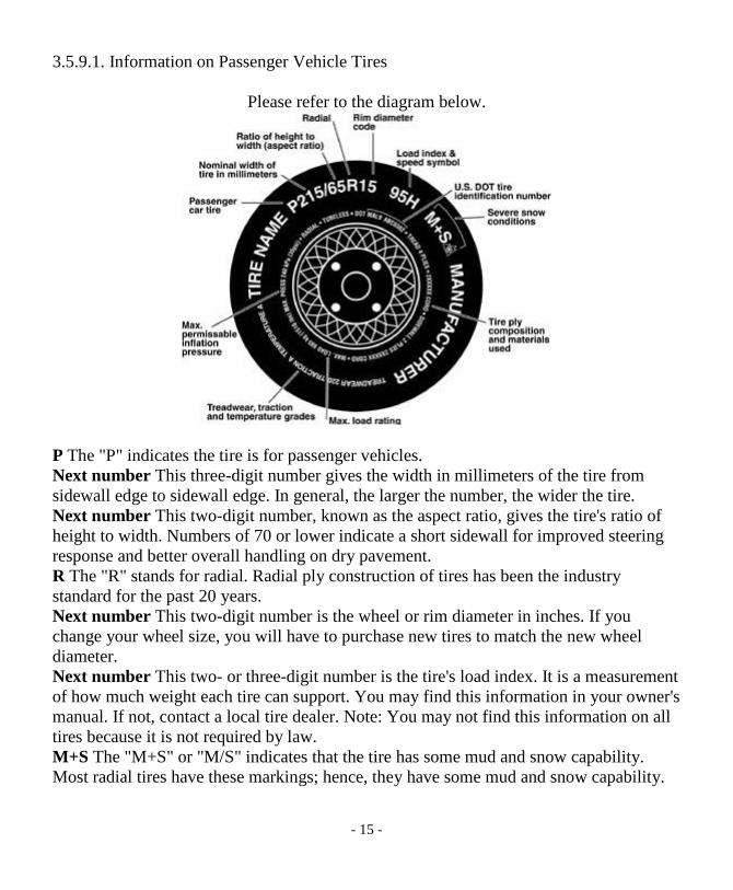
3.5.9.1. Information on Passenger Vehicle Tires
Please refer to the diagram below.
P The "P" indicates the tire is for passenger vehicles.Next number This three-digit number gives the width in millimeters of the tire fromsidewall edge to sidewall edge. In general, the larger the number, the wider the tire.Next number This two-digit number, known as the aspect ratio, gives the tire's ratio ofheight to width. Numbers of 70 or lower indicate a short sidewall for improved steeringresponse and better overall handling on dry pavement.R The "R" stands for radial. Radial ply construction of tires has been the industrystandard for the past 20 years.Next number This two-digit number is the wheel or rim diameter in inches. If youchange your wheel size, you will have to purchase new tires to match the new wheeldiameter.Next number This two- or three-digit number is the tire's load index. It is a measurementof how much weight each tire can support. You may find this information in your owner'smanual. If not, contact a local tire dealer. Note: You may not find this information on alltires because it is not required by law.M+S The "M+S" or "M/S" indicates that the tire has some mud and snow capability.Most radial tires have these markings; hence, they have some mud and snow capability.

- 16 -
Speed Rating The speed rating denotes the speed at which a tire is designed to be drivenfor extended periods of time. The ratings range from 99 miles per hour (mph) to 186mph. These ratings are listed below.
NOTE: You may not find this information on all tires because it is not required by law.
Tire Safety Information
Letter Rating Speed RatingQ 99 mphR 106 mphS 112 mphT 118 mphU 124 mphH 130 mphV 149 mphW 168* mphY 186* mph
* For tires with a maximum speed capability over 149 mph, tire manufacturers sometimesuse the letters ZR. For those with a maximum speed capability over 186 mph, tiremanufacturers always use the letters ZR.U.S. DOT Tire Identification Number This begins with the letters "DOT" and indicatesthat the tire meets all federal standards. The next two numbers or letters are the plantcode where it was manufactured, and the last four numbers represent the week and yearthe tire was built. For example, the numbers 3197 means the 31st week of 1997. Theother numbers are marketing codes used at the manufacturer's discretion. Thisinformation is used to contact consumers if a tire defect requires a recall.Tire Ply Composition and Materials Used The number of plies indicates the number oflayers of rubber-coated fabric in the tire. In general, the greater the number of plies, themore weight a tire can support. Tire manufacturers also must indicate the materials in thetire, which include steel, nylon, polyester, and others.Maximum Load Rating This number indicates the maximum load in kilograms andpounds that can be carried by the tire.Maximum Permissible Inflation Pressure This number is the greatest amount of airpressure that should ever be put in the tire under normal driving conditions.

- 17 -
3.5.9.2. UTQGS InformationTreadwear Number This number indicates the tire's wear rate. The higher the treadwearnumber is, the longer it should take for the tread to wear down. For example, a tire graded400 should last twice as long as a tire graded 200.Traction Letter This letter indicates a tire's ability to stop on wet pavement. A highergraded tire should allow you to stop your car on wet roads in a shorter distance than a tirewith a lower grade. Traction is graded from highest to lowest as "AA","A", "B", and "C".Temperature Letter This letter indicates a tire's resistance to heat. The temperaturegrade is for a tire that is inflated properly and not overloaded. Excessive speed,underinflation or excessive loading, either separately or in combination, can cause heatbuild-up and possible tire failure. From highest to lowest, a tire's resistance to heat isgraded as "A", "B", or "C".3.5.9.3. Additional Information on Light Truck Tires
Please refer to the following diagram.
Tires for light trucks have other markings besides those found on the sidewalls ofpassenger tires.LT The "LT" indicates the tire is for light trucks or trailers.ST An "ST" is an indication the tire is for trailer use only.Max. Load Dual kg (lbs) at kPa (psi) Cold This information indicates the maximumload and tire pressure when the tire is used as a dual, that is, when four tires are put oneach rear axle (a total of six or more tires on the vehicle).

- 18 -
Max. Load Single kg (lbs) at kPa (psi) Cold This information indicates the maximumload and tire pressure when the tire is used as a single.Load Range This information identifies the tire's load-carrying capabilities and itsinflation limits.
3.6. TIRE SAFETY TIPSPreventing Tire DamageSlow down if you have to go over a pothole or other object in the road.Do not run over curbs or other foreign objects in the roadway, and try not to strike thecurb when parking.
Tire Safety ChecklistCheck tire pressure regularly (at least once a month), including the spare.Inspect tires for uneven wear patterns on the tread, cracks, foreign objects, or other signsof wear or trauma.Remove bits of glass and foreign objects wedged in the tread.
Make sure your tire valves have valve caps.Check tire pressure before going on a long trip.Do not overload your vehicle. Check the Tire Information and Loading Placard or User’sManual for the maximum recommended load for the vehicle.
4. SAFE TOWING GUIDELINES
All of the employees on Team BUSHTEC wish to thank you for your purchase of thefinest touring cargo trailer made in the world. Please take a few moments to review thecontents of this Owner’s Manual to insure thousands of trouble-free miles of use.Remember, this is only a guide and should be a supplement to your own regard for safeoperation.
CAUTION: FAILURE TO PERFORM WHEEL BEARING SERVICE ASDESCRIBED HEREIN MAY CAUSE THE TRAILER TO TRACK UNDESIRABLYAND WILL VOID WARRANTY!!!
WARNING: TOWING A TRAILER BEHIND A MOTORCYCLE INCREASES THELIKELIHOOD OF INJURY OR DEATH TO BOTH OPERATOR AND PASSENGERDUE TO INCREASED RISK AND EXPOSURE. FAILURE TO OBSERVE ANDFOLLOW;

- 19 -
(A) ALL RULES OF THE ROAD AND LAWS OF THE LAND;(B) MAINTENANCE AND OPERATION INSTRUCTIONS ASSOCIATED
WITH THIS TRAILER;(C) POSTED SPEED AND ROAD CONDITION WARNINGS; and(D) SAFE RIDING PRACTICES AND PROCEDURES;
WILL FURTHER INCREASE THE RISK OF INJURY OR DEATH TO OPERATORAND PASSENGER.
We are not aware of any current state or federal guidelines for pulling a trailer with amotorcycle. We suggest when pulling and loading a trailer you do not exceed themanufacturers Gross Vehicle Weight limits.When pulling a trailer with a motorcycle, extra distance must be allowed for stopping.When cornering, use slower speeds and a wider angle of attack.Use extra caution at all times, particularly if the road surface is wet or slippery.Splitting lanes with a trailer is HIGHLY discouraged and is ILLEGAL in many states.Behind most touring motorcycles, your mirrors are wider than your BUSHTEC trailer.BPC supports the Motorcycle Safety Foundation. If you have never taken a course, BPChighly recommends it! Contact the MSF office nearest you.
5. LOADING AND TONGUE WEIGHTS
Tongue weight is a much-discussed aspect of trailer use. Too much is bad, not enough isbad, so how do you determine the happy medium? Fact is, a trailer will wander if tongueweight is not sufficient to give the trailer “direction”. Without “direction”, all trailerswill wander behind the tow vehicle and cause handling problems. Insufficient tongueweight will result in erratic trailer handling. Excessive tongue weight will cause couplerfatigue, hitch fatigue or failure and increased wear and tear on the tow vehiclesmechanical components.
Trailer Industry standards suggest a ratio of 10% to 15% of the trailers gross vehicleweight (GVW- base weight of trailer and its cargo) be applied to the coupler as an idealtongue weight. This weight is easily measured by using a bathroom scale or fish scale,weighing the applied load at the ball or coupler. This method of weighing must allowthat the coupler is at the installed or operational height to determine the actual tongueweight during use.

- 20 -
Loading of cargo is a major determinant of tongue weight. Load placement anddistribution must be executed carefully and thoughtfully, with added consideration givento additional weight in and on accessory items such as coolers and luggage racks.Adding or subtracting load must be accomplished with the same care and thought as theoriginal loading was given, and tongue weight rechecked!
WARNING: ALWAYS LOAD CARGO SO THAT HEAVIEST ITEMS ARELOWEST AND DISTRIBUTED FRONT TO REAR. NEVER PUT THE HEAVIESTITEM AT THE REAR OF THE TRAILER, AS THIS WILL INCREASE THETRAILERS TENDENCY TO SWAY. LOADING THE TRAILER IN EXCESS OFTHE GVWR (gross vehicle weight rating) IS DANGEROUS AND COULD CAUSESERIOUS PERSONAL INJURY OR DEATH.
WARNING: IF THE TRAILER FAILS TO HANDLE IN A SAFE ANDPREDICTABLE MANNER, STOP! DO NOT OPERATE THE TRAILER UNTILYOU HAVE DETERMINED AND CORRECTED THE CONDITION OR PROBLEM.
6. LID LATCH OPERATION, OPENING & CLOSURE
CAUTION: DO NOT SLAM THE LID ON ANY BUSHTEC TRAILER. ALLBUSHTEC TRAILERS FEATURE SOFT CLOSURE LID SYSTEMS. SLAMMINGOF THE LID TO CLOSE THE TRAILER CAN RESULT IN DAMAGE ORBREAKAGE AND FAILURE OF OPERATION OF THE LATCH SYSTEM.
NOTE: It is possible to lock the keys inside of your Bushtec trailer. Check that keys arenot inside the trailer prior to closing the lid.TURBO+2™To Open: Push downward on the recessed logo area of the lid while pushing the lockbutton in. While the lock button remains fully depressed, lift upward on the lid.
To Close: DO NOT DROP OR SLAM. Bring the lid down and allow to set on the latch.Push lock button in and push lid closed. Release push button allowing the latch toengage and lid should not be able to be lifted open.
To Lock: Insert key into keyhole and rotate. Press button and check.

- 21 -
NOTE: Lock must be unlocked in order to open the lid on Turbo+2™ model. It ispossible to lock the keys in the trailer. Check that you have your keys before closing thelid.
ROADSTAR™To Open: Push downward on the lid handle while pushing the lock button in. While thelock button remains fully depressed, lift upward on the lid.
To Close: DO NOT DROP OR SLAM. The latch features a two-stage rotary mechanism.Close the lid and push down gently. This will engage the first stage. Then push downfirmly to engage the second stage, which will click. Pull up on handle to check lid issecurely closed. When the latch in fully engaged, the lid should have no movement.
To Lock: Insert key into keyhole and rotate. Push button to check.
CAUTION: THE SECOND STAGE OF THE LATCH MUST BE ENGAGED TOKEEP THE LID SECURELY CLOSED.
QUANTUM SPORT™ or QUANTUM “GL”™To Open: Push down on the back of the lid behind the third brake light or over eitherfoot of the Aerowing if the trailer is equipped with the Aerowing. This is to removespring tension on the latch. Pull out on the paddle handle until the latch releases, hold,and lift the lid.
NOTE: Due to spring tension generated by the seal, it may feel as though the paddlehandle is fully extended but the lid will not open. Pull out further on the paddle handleand the latch will release.
To Close: DO NOT DROP OR SLAM. The latch features a two-stage rotarymechanism. Bring lid down and push gently to engage the first stage of the latch. Placeyour hand on the rear of the lid behind the third brake light if equipped with the standardlid. If the trailer is equipped with the Aerowing, place the palms of your hands over thefeet of the wing, NOT the middle of the wing. Push down firmly until the second stageengages, which will click. The lid should have no movement and should not be able tobe lifted open when the latch is properly closed
To Lock: Insert key into keyhole and rotate. Check paddle.

- 22 -
CAUTION: IF THE QUANTUM™ IS EQUIPPED WITH THE AEROWINGOPTION, DO NOT PUSH DOWN ON THE CENTER OF THE WING. PUSH DOWNOVER THE FEET OF THE WING, AS MARKED. FAILURE TO DO SO COULDRESULT IN THE WING CRACKING.
ENTOURAGE™To Open: Push the lock button in. While the lock button remains fully depressed, liftupward on the lid.
To Close: DO NOT DROP OR SLAM. Bring the lid down and allow to set on the latch.Push downward on lid to engage latch. Lid should not be able to be lifted open.
To Lock: Insert key into keyhole and rotate. Press button and check.
NOTE: Lock must be unlocked in order to open the lid on Entourage™ model. It ispossible to lock the keys in the trailer. Check that you have your keys before closing thelid.
NOTE: All BUSHTEC Trailers have an extremely airtight seal. Opening and closingthe lid requires pushing down on the lid to remove tension created by lid sealcompression.
CAUTION: DO NOT ALLOW PLASTIC BAGS (E.G.- GROCERY BAGS) NEARTHE GAS LID PROPS. PLASTIC CAN WORK ITS WAY INTO THE SEALS ANDCAUSE THEM TO LEAK.
7. ATTACHING TRAILER TO MOTORCYCLE
NOTE: When connecting the trailer to the motorcycle, be sure that the trailer is loaded,and that tongue weight and wheel alignment has been checked.
CAUTION: IF THE TRAILER IS EQUIPPED WITH A TONGUE STAND MAKESURE IT IS IN THE UPRIGHT STOWED POSITION.
LOCKING HITCH PIN: (Smooth body, barrel style key)Place the hole in captured ball of the heim joint over the hitch pin. Place the key into thelock, hold the lock and turn the key ¼ turn clockwise to unlock. Place the lock on top ofthe pin down against heim joint ball and turn the key ¼ turn counterclockwise to lock.

- 23 -
Remove the key. Lift up on the lock to insure lock is engaged on the pin. Cover keyholewith supplied rubber cap which is designed to keep the keyway free of debris.
After securing the trailer to the motorcycle, connect the wiring harness; preferably run theharness over the top of the chassis neck. Secure the safety chain to the safety chainmount. Check all connections for completeness.
NOTE: The heim joint must be approximately perpendicular to the hitch pin or the lockwill not seat properly. If the lock does not seat, rotate the heim joint so that it isperpendicular to the pin.
CAUTION: FAILURE TO USE THE SUPPLIED RUBBER CAP WILL RESULT INDIRT AND DEBRIS SETTLING INTO THE KEYHOLE. THIS MAY PREVENTYOU FROM BEING ABLE TO INSERT THE KEY AND REMOVE THE LOCK.
WARNING: IF THE TRAILER IS NOT SECURELY ATTACHED TO THEMOTORCYCLE, IT COULD UNCOUPLE FROM THE MOTORCYCE. THE KEYCAN BE REMOVED FROM THE LOCK REGARDLESS OF WHETHER OR NOTTHE LOCK IS ENGAGED ON THE HITCH PIN.
CAUTION: WHEN THE TRAILER IS NOT IN USE, DO NOT LEAVE THE LOCKON THE HITCH PIN. REMOVE IT AND STORE OFF OF THE HITCH PIN UNTILITS NEXT USE. LEAVING THE HITCH LOCK IN PLACE DURING OPERATIONWITHOUT THE TRAILER ATTACHED COULD ALLOW DIRT AND MOISTURETO ENTER THE LOCK THROUGH THE BOTTOM AND COULD LEAD TOPREMATURE HITCH LOCK FATIGUE AND/OR FAILURE.
8. MAINTENANCE
The following section is broken into subsections, BEFORE EACH USE, AFTERINITIAL 50 MILES, AFTER INITIAL 500-1000 MILES, AT 3000 MILES ANDEVERY 3000 MILES, REMOVAL FROM STORAGE, and MISCELLANEOUS. Eachoperation will take a maximum of 10 minutes to perform and will aid in the longevity ofyour investment.

- 24 -
BE
FO
RE
EA
CH
US
E
AF
TE
RIN
ITIA
L50
MIL
ES
AF
TE
RIN
ITIA
L500
-1
000M
ILE
S
AT
3000
AN
DE
VE
RY
3000
MIL
ES
RE
MO
VA
LF
RO
MS
TO
RA
GE
MIS
C.
COUPLER CONDITIONX X X X
GENERAL HARDWARE INSPECTIONX X X
LUBRICATE HEIM JOINTX X
LUBRICATE 360 DEGREE SWIVELX X
LUBRICATE SUSPENSION COLLARSX X X
CHECK TIRE PRESSURE AND WEARX X X
TONGUE HARDWAREX X X
WHEEL SERVICEX X
COUPLER CONDITIONCheck that the captured ball in the front of the heim joint moves freely without binding,but does not have excessive play. Check that the 360-degree swivel has full movementwith moderate resistance. There should be no fore and aft play in the swivel assembly.When the trailer is attached, check your hookup to insure that the coupler is secure, yourlights are plugged in and that your safety chain is attached.

- 25 -
GENERAL HARDWARE INSPECTION
TOOLS REQUIRED7/16, ½, 9/16 inch wrenches
Visually inspect all components for structural integrity, fitment, and completeness.Check all hardware and fittings for proper tension.
HEIM JOINT LUBRICATION
TOOLS REQUIREDCartridge Grease Gun
Lubricate the captured ball via the zerk fitting in the side of the heim joint using goodquality grease designed for automobile use. Turn the captured ball while lubricating.Inspect the heim joint for wear, that the captured ball is free, and that the heim is notbent.
NOTE: The zerk fitting in the heim joint is NOT equipped with a check ball. Uponremoval of the grease gun, grease may backflow out of the zerk fitting. Allow to purgeand wipe off excess.
CAUTION: THE HEIM JOINT CAN BE BENT IF THE CAPTURED BALL ISFORCED TO TRAVEL BEYOND ITS ROTATIONAL LIMIT. APPROACH STEEPINCLINE CHANGES (DRIVEWAY TO STREET) AT AN ANGLE TO ALLOW THESWIVEL PORTION OF THE COUPLER TO ENGAGE THE CHANGE RATHERTHAN THE CAPTURED BALL.
360-DEGREE SWIVEL LUBRICATION
TOOLS REQUIREDCartridge Grease Gun7/8 inch WrenchLubricate the grease fitting on the underside of the tongue forward of the safety chain,using a good quality grease designed for automobile use. While greasing the swivel,continuously turn the swivel using a 7/8-inch wrench placed on the heim joint to allowgrease to penetrate the mechanism.

- 26 -
NOTE: YOU MUST ROTATE THE HEIM JOINT ASSEMBLY CONTINUOUSLYWHILE PUSHING GREASE INTO THE FITTING. FAILURE TO ROTATE WILLNOT ALLOW GREASE TO PENETRATE SWIVEL ASSEMBLY.
SUSPENSION LUBRICATION
TOOLS REQUIREDSuper Lube® or similar lubricant
Lubricate the six collars that attach the anti-sway bar to the A-arms and suspension stopplates on the underside of the chassis. Place 2-3 drops of a good quality Teflon®-basedlubricant on each edge of each of the six points. The lubricant will be placed onto theanti-sway bar or A-arm at each end of each collar. Super Lube®, DuPont™ Multi-Usewith Teflon® or Dri-Slide® are preferred lubricants. Super Lube® is available fromBPC, and these products may also be found at Home Depot™ or Lowe’s™ homeimprovement centers. Either dropper or aerosol dispenser may be used.
NOTE: DO NOT USE ANY TYPE OF WHEEL BEARING OR LITHIUM GREASE,CHAIN LUBE OR WD-40® FOR SUSPENSION LUBRICATION. THESELUBRICANTS WILL ATTRACT DIRT AND, BECAUSE OF THEIR VISCOSITY,WILL NOT ALLOW THE SUSPENSION TO OPERATE PROPERLY.
TIRE PRESSURE
TOOLS REQUIREDCalibrated Tire Gauge

- 27 -
Adjust 3.00x16 tires to 35 PSI cold, regardless of load. Improper inflation will increaserolling resistance and decrease fuel mileage, as well as increase tire wear. Spin-balancewheels annually or every 10,000 miles, whichever comes first. Failure to re-balance willshorten tire life and result in irregular wear.
CAUTION: LOW TIRE PRESSURE CAN CAUSE UNDESIRED HANDLING ANDWILL SHORTEN TIRE LIFE.
TONGUE HARDWARE
TOOLS REQUIRED7/16, ½, 9/16 inch wrenches.
Check the tension on the two bolts which secure the tongue to the main chassis tube.Check the two nuts on the third body support clamp at front of body and the two nutssecuring the third body support plate to the body. This is especially important with theaddition of the cooler package.
WHEEL SERVICE
TOOLS REQUIRED15/16-inch wrenchCartridge Grease GunWire BrushMedium Duty Threadlock (blue or green)
1. Refer to section regarding hub cover removal for instructions according to wheeltype.
2. Remove the 5/8-inch nylock axle nut from the spindle using a 15/16-inch wrench.3. Lift trailer and pull out on hub to remove wheel.4. Inspect integrity of wheel bearings by placing one finger into each bearing, lift
wheel and spin slowly. If any binding, grinding, or looseness is detected, thebearing needs to be replaced.
5. Clean the spindle threads with a wire brush to remove old Threadlock.6. Place a light coat of good quality automotive grease on the unthreaded portion of
the axle shaft for water displacement and corrosion resistance.
- 28 -
7. Reinstall the wheel onto the axle shaft, with the balanced side facing in. Placetwo to three (2-3) drops of medium duty (blue or green) Threadlock onto the axlethreads. NEVER USE RED THREADLOCK.
CAUTION: DO NOT ALLOW THE THREADLOCK TO BOND THE WHEELBEARING TO THE SPINDLE OR PENETRATE THE WHEEL BEARING.EXCESSIVE THREADLOCK CAN DAMAGE INTERNALS OF THE BEARING.
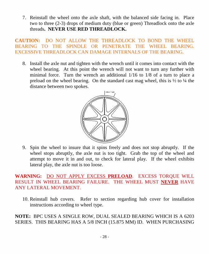
8. Install the axle nut and tighten with the wrench until it comes into contact with thewheel bearing. At this point the wrench will not want to turn any further withminimal force. Turn the wrench an additional 1/16 to 1/8 of a turn to place apreload on the wheel bearing. On the standard cast mag wheel, this is ½ to ¼ thedistance between two spokes.
9. Spin the wheel to insure that it spins freely and does not stop abruptly. If thewheel stops abruptly, the axle nut is too tight. Grab the top of the wheel andattempt to move it in and out, to check for lateral play. If the wheel exhibitslateral play, the axle nut is too loose.
WARNING: DO NOT APPLY EXCESS PRELOAD. EXCESS TORQUE WILLRESULT IN WHEEL BEARING FAILURE. THE WHEEL MUST NEVER HAVEANY LATERAL MOVEMENT.
10. Reinstall hub covers. Refer to section regarding hub cover for installationinstructions according to wheel type.
NOTE: BPC USES A SINGLE ROW, DUAL SEALED BEARING WHICH IS A 6203SERIES. THIS BEARING HAS A 5/8 INCH (15.875 MM) ID. WHEN PURCHASING

- 29 -
REPLACEMENT BEARINGS FROM A SOURCE OTHER THAN BUSHTEC,SPECIFY THE ID TO ASSURE FITMENT.
CAST WHEEL HUB COVER, CHROME HEX STYLETOOLS REQUIRED5/64” Allen wrench
Removal: Using 5/64” Allen wrench, loosen the three Allen head set screws two to threeturns. Pull hub cover off of wheel hub.
Installation: Check that the setscrews do not protrude inside hub cover. Place hub coverover hub of wheel and push on until three internal stops make contact with the hub face.Using the 5/64” Allen wrench, tighten the three Allen head set screws in an alternatingpattern until snug against the hub of the wheel.
CAUTION: DO NOT OVERTIGHTEN! MAKE SURE SETSCREWS ARE SNUGAGAINST HUB AND PULL ON COVER TO CHECK PROPER TENSIONING. SPINTHE WHEEL TO MAKE SURE THE HUB COVER IS ON STRAIGHT AND DOESNOT CONTACT ANY OTHER PARTS.
FORGED WHEEL HUB COVERTOOLS REQUIRED3/16” Allen wrench
Removal: Using 3/16” Allen wrench, loosen the single Allen head set screw until almostremoved from hub cover. Pull hub cover off of wheel hub.
Installation: Check that the setscrew does not protrude inside hub cover. Place hub coverover hub of wheel and push on until fully seated against hub face. Using the 3/16” Allenwrench, tighten the single Allen head set screw until snug against the hub of the wheel.
CAUTION: DO NOT OVERTIGHTEN! MAKE SURE SETSCREW IS SNUGAGAINST HUB AND PULL ON COVER TO CHECK PROPER TENSIONING. SPINTHE WHEEL TO MAKE SURE THE HUB COVER IS ON STRAIGHT AND DOESNOT CONTACT ANY OTHER PARTS.
REMOVAL FROM STORAGEPerform the designated services according to the chart.

- 30 -
MISCELLANEOUSTires should be checked for signs of weathering, checking, cracking, or irregular wear. Iftires exhibit any of the above signs or have less than 1/8 inch of tread on the middle ofthe tread face, the tires should be replaced.
9. SUSPENSION OPERATION
The BUSHTEC air suspension must be inflated so as to maintain a constant verticalalignment of the wheel with the road surface, regardless of pressure. As your cargo loadschange, it may be necessary to increase or decrease the suspension air pressure and rollthe trailer to determine the correct wheel alignment.
Operation: Inflate the suspension to 50 PSI so that the wheels are in the “positivecamber” position (wheels cambered out at top). Place cargo load inside trailer,establishing proper tongue weight. Roll the trailer and check the camber position of thewheel. If positive camber is evident, simultaneously release air while walking the trailerforward until the wheels are properly aligned. If negative camber is evident, add air tobring the wheels to a positive camber position and repeat previous step. On most Bushtecmodels, proper wheel alignment is achieved with a straight up wheel alignment, orneutral camber. On Entourage™ models equipped with fender skirts, it is difficult todetermine the camber position of the wheel. BPC recommends aligning the A-armbetween just below the centerpoint of the upper and lower suspension stops on theunderside of the trailer. The upper suspension stop is the point at which the chassis iscompletely compressed with the A-arm bump stop against the body band, representingmaximum negative camber. The lower suspension stop is an L-shaped bracket that limitsthe A-arm from traveling any further away from the body and represents maximumpositive camber. On Turbo+2™ models equipped with the Aerowing aerodynamic lidwing, proper alignment is achieved when the wheels are slightly cambered out at the topto account for downforce generated by the Aerowing at speed (2-4 degrees).
Top pair shows positive camber.
Center pair shows correct neutral camber.
Bottom pair shows negative camber.

- 31 -
CAUTION: THE BUSHTEC AIR SUSPENSION IS A HIGH PRESSURE/ LOWVOLUME SYSTEM AND SHOULD NEVER BE ADJUSTED WITH GAS STATIONAIR SYSTEMS. THESE SYSTEMS TYPICALLY RUN UNREGULATED LINEPRESSURE, MAKING IT DIFFICULT TO CONTROL AIRFLOW. WERECOMMEND THE USE OF THE PROGRESSIVE AIR PUMP WITH GAUGE,AVAILABLE FROM BUSHTEC.
NOTE: ALWAYS ROLL THE TRAILER AFTER INFLATION CHANGES TODETERMINE THE MOTIVE POSITION OF THE WHEELS. PRESSURE IS ANIRRELEVANT MEASURE OF SUSPENSION INFLATION, AND SHOULD ONLYBE USED FOR A REFERENCE. THE SUSPENSION SYSTEM IS CAPABLE OF 150PSI.
CAUTION: OPERATION OF THE TRAILER WITHOUT SUFFICIENTSUSPENSION AIR PRESSURE (NEGATIVE CAMBER) MAY CAUSE DAMAGETO THE SUSPENSION COMPONENTS AND ROUGH HANDLINGCHARACTERISTICS. OVERINFLATION WILL CAUSE JUMPY HANDLING ANDTRACKING IN ADDITION TO THE DANGER OF AIR SHOCK SEAL FAILUREAND THE INABILITY TO MAINTAIN AIR PRESSURE IN THE SUSPENSION.
NOTE: SUSPENSION OPERATION WILL BE STIFF DURING THE FIRST 500 TO1000 MILES MAKING ADJUSTMENT TOUCHY. STIFFNESS WILL SUBSIDEAFTER 500 TO 1000 MILES. ALWAYS ROLL TRAILER FORWARD BEFOREDETERMINING CAMBER POSITION.
10. MOUNTING AND OPERATION OF TONGUE STAND
TOOLS REQUIRED½ inch Wrench
Mounting: The tongue stand should be mounted so that the end of the leg in the retractedposition is no lower than the bottom bend in the chassis neck. The higher it can bemounted, the more clearance you will achieve, but it should not be so high that the trailercan be attached to the motorcycle while on the centerstand and the tongue stand down.
Operation: To stow the tongue stand, pull downward on the leg until the pin is clear ofthe notch and push backward until the pin engages the notch at the upper rear. To deploy

- 32 -
the stand, pull the leg toward the back of the trailer until the pin clears the rear notch andfold the leg downward until the pin engages the bottom notch.
CAUTION: DO NOT ATTACH TRAILER TO MOTORCYCLE WITH TONGUESTAND DEPLOYED. THE TONGUE STAND IS NOT DESIGNED TO BE LEFTDOWN WHILE THE TRAILER BEING TOWED.
11. MOUNTING AND OPERATION OF COOLER PACKAGE
TOOLS REQUIRED½ inch Wrench
Mounting: Mount the cooler rack with the stepped support towards the rear of the trailer.On Turbo+2™ trailers, Quantum™, Roadstar™ and Entourage™ models, the frontclamp should fit around the neck just behind the skid hoop on the underside of thetongue. Place U-clamp around chassis neck from underside, place saddle over top ofneck with clamp ends through holes. Next, set rack over clamp assembly with clampends through holes in rack and secure with nuts. Install clamp assembly in the sameorder as above for rear of rack. Level rack and tighten nuts evenly in an alternatingpattern, until snug. Check that rack is secure. After installing the rack, place the coolerand cover on the rack and snap the cover down around the rack. Carefully open thetrailer lid to insure that the trailer lid or luggage rack does not rub on the cooler cover. Ifthe cooler is too close, loosen the cooler rack hardware and move it away from the frontof the trailer body until proper clearance is achieved.
CAUTION: THE COOLER AND THE LID CANNOT BE OPENED AT THE SAMETIME ON SOME TURBO TRAILERS.

- 33 -
CAUTION: WHEN BACKING THE MOTORCYCLE WITH THE TRAILERATTACHED, IT IS POSSIBLE TO “JACKKNIFE” AND CAUSE THE COOLER TOMAKE CONTACT WITH THE REAR END OF THE MOTORCYCLE. HAVESOMEONE WATCH THE BACK OF THE MOTORCYCLE WHEN BACKING.
Cooler Operation: To open the cooler, lift the top skirt over the zipper. Grab the zipperby the tassel and unzip by pulling around front and to the opposite side rear. Fold backcover and open cooler lid by lifting on lid recess at front. To close, close cooler lid andfold cooler cover over top to cooler. Zip closed by pulling tassel on zipper and pullaround the front and to the opposite side rear. Fold down skirt over zipper on top ofcover.
CAUTION: FAILURE TO CLOSE COOLER COVER CAN RESULT IN DAMAGETO FINISH BY COVER.
Drain OperationTo Remove: Lift the brass handle until it is straight up, and lift plug out.To Install: Place plug in drain hole and fold handle over. This compresses the plugbetween the top and bottom plates and causes the plug to expand. You should not be ableto pull the plug out of the hole easily with the handle folded over.To Adjust: If the drain leaks, adjust as follows; with lever folded so that it pointsupward, hold the rubber body and metal plate at the bottom of the drain. Tighten handleby turning clockwise, like a bolt 1/8 to ¼ of a turn at a time. If the handle cannot befolded down, the handle needs to be loosened by turning counterclockwise 1/8 to ¼ turnat a time.
12. GARMENT BAG (TURBO+2™, QUANTUM SPORT™, and QUANTUM“GL”™) & ACCESSORY LID BAG (ALL MODELS)
GARMENT BAGThe garment bag is secured to the steel lid frame via snaps on the garment bag around itsperimeter. All of the snaps except for the top center snap on the garment bag are standardsnaps. The top center snap is a locking snap, identified by the writing “PULL THE DOT”on the face. The locking snap is installed bottom first and removed top first.
ACCESSORY LID BAG

- 34 -
The Accessory Lid Bag is secured to the steel lid frame via snaps on the lid bag aroundits perimeter. All of these snaps are standard snaps.
13. REMOVAL AND INSTALLATION OF STONE PROTECTOR BRA
TURBO+2™, ROADSTAR™, & ENTOURAGE™These models each have 2 locking snaps, one on each side of the bra. The locking snap isidentified by the writing “PULL THE DOT” on the face of each locking snap stud. Onthe Turbo+2™, Entourage™, and Roadstar™ with Standard fenders, the locking snap isremoved bottom first and installed top first. On the Roadstar™ with the GT fenders, thelocking snap is removed front first and installed rear first. The locking snap goes on andcomes off over the snap stud at an angle.
The stone protector bra fits snugly on all models and is made more pliable by warmingthe bra prior to installation. This can be accomplished by laying the bra in the sun.
CAUTION: THE STONE PROTECTOR BRA SHOULD BE REMOVED WHENWASHING THE TRAILER REGULARLY TO REMOVE DEBRIS AND GRIT FROMBETWEEN THE PAINT AND VINYL. FAILURE TO DO SO MAY RESULT INABRASION AND DAMAGE TO THE PAINTED FINISH.
14. LUGGAGE RACK
TURBO+2™, QUANTUM SPORT™ and QUANTUM “GL”™ MODELSThe luggage rack for the Turbo+2™, Quantum Sport™ and Quantum “GL” modelsconsists of 4 rails. The luggage rack has a maximum weight rating of 75 pounds, spreadevenly over the 4 rails. The four adjustable sliding tie downs can be loosened and slid toposition for securing of cargo. Use bungee nets or cords to secure cargo.
ROADSTAR™The luggage rack for the Roadstar™ consists of a chrome tubular steel rack. The luggagerack has a maximum weight rating of 25 pounds.
NOTE: Items secured to luggage rack must be counted toward gross weight. Do notplace heavy items on rack to avoid affecting center of gravity.

- 35 -
15. INTERIOR LIGHT
The interior light is run via its own wire in the primary harness. During a typicalinstallation, it is connected into the running lights on the motorcycle. Per thisinstallation, if the light is left on but the ignition is turned off, the light will go off. Thelight can be hooked to the accessory terminal or directly to the battery, but must be fusedand adds opportunity for battery drain if the light is left on.
CAUTION: THE INTERIOR LIGHT SHOULD BE TURNED OFF WHEN NOT INUSE TO AVOID UNNECESSARY BATTERY DISCHARGE.
CAUTION: IF LEFT ON FOR EXTENDED PERIODS, THE INTERIOR LIGHTLENS WILL BECOME EXTREMELY HOT. DO NOT TOUCH THE LENS AND DONOT ALLOW ITEMS TO MAINTAIN CONTACT WITH THE LENS, AS THEYMAY MELT OR BE DAMAGED.
16. WIRE HARNESS COLOR CODES
Following are the primary wiring harness functions identified by color.
GREEN: RUNNING & TAILLIGHTSWHITE: GROUNDBLUE: BRAKE LIGHTSYELLOW: RIGHT TURN SIGNALBROWN: LEFT TURN SIGNALBLACK: INTERIOR LIGHT- SEE SECTION 12
NOTE: Bushtec recommends the use of an Electronic Relay Isolator package on mostnew motorcycle installations. The Electronic Relay Isolator package creates a separateelectrical path for trailer lighting and helps avoid damage to the motorcycles harness bymaintaining internal voltage levels. Trailer lighting is powered directly from the battery.
NOTE: Bushtec recommends using electrical or battery grounds as opposed to framegrounds.

- 36 -
17. SPECIFICATIONS
ROADSTAR™ TURBO+2™ QUANTUM™ ENTOURAGE™SPORT & “GL”
BASE WEIGHT (LBS)* 125 125 140 140CARGO AREA DIMENSIONS (inches)**Height 18 16 16 15Length 38.5 43 45 50Width 22.5 22.5 22.5 22.5MAXIMUM CARGO DIMENSIONS (inches)***Height 24 23 24Length 52 54 54 58Width 40 38 38 41VOLUME (Cubic Feet) 21 25 26 22OVERALL LENGTH (inches) 87 87 89 92LOAD CAPACITY (GVWR) 350 350 350 350(LBS.)
*-Approximate Weight**-Dimensions at narrowest interior points.***-Dimensions at widest exterior points.
NOTE: Specifications are subject to change at any time without prior notice.
18. CERTIFICATION LABEL LOCATIONEvery BPC trailer is assigned its own unique WMI compliant VIN number which islocated on a Certification label on the trailer chassis. The VIN tag is located on thechassis neck under the nose of the body and can be viewed from the left side of thetrailer. Besides containing the year, make, model, and VIN number, it also containsinformation on axle weight rating, gross vehicle weight rating, rim size, tire size and tirepressure information, and it indicates that the trailer meets all DOT requirements.
19. LIGHTING ACCESS & SERVICEEach Bushtec model features unique and distinctive lighting styles which requiredifferent methods of accessing bulbs for replacement. On the Quantum Sport™ andQuantum “GL”™ models, the taillight recess cover must be removed to facilitatechanging of taillight bulbs.

- 37 -
REMOVAL OF TAILLIGHT RECESS COVEROn the Quantum Sport™ and Quantum “GL”™ models the taillight housing recess iscovered with a removable cover. The cover is held in place with two screw fasteners.The panel can be removed by supporting the panel and loosening and removing eachfastener. Once the fasteners are removed, the panel will be loose. Note engagement holeplacement and that the interior light, if so equipped, is mounted on this panel and pluggedinto the harness. If it is necessary to fully remove the cover and unplug the light, note theconnection locations and color codes.
TAILLIGHT & TURNSIGNAL BULB REPLACEMENT
TURBO+2™Taillight and turnsignal- From the outside of the trailer using a Phillips head screw driver,loosen and remove the screws that hold the corresponding lens in place to access thebulb.
ROADSTAR™Taillight and turnsignal- From the outside of the trailer using a Phillips head screw driver,loosen and remove the screws that hold the corresponding lens in place to access thebulb.
QUANTUM SPORT™Taillight and turnsignal- Open the trailer and remove the taillight recess cover asdescribed above. The bulb base holders twist out of the back side of the housing.
QUANTUM “GL”™Taillight and turnsignal- Open the trailer and remove the taillight recess cover asdescribed above. Remove the three nuts from the studs in the light housing base andcarefully remove the light housing from the recess. The bulb holders twist out of theback side of the housing. Reapply a sealant around threaded studs and wiring hole whenreinstalling, pulling any excess harness back into the body, out of the recess.
ENTOURAGE™Taillight and turnsignal- The taillight combination on the Entourage™ is LED. Thetaillight is held in place by nuts and lock washers inside the body, securing studs passingthrough the body from the bezel. The carpet must be pulled loose to access the backsideof the taillight bucket for removal. The taillights on the Entourage™ use a module tosend the appropriate signal to the taillight to differentiate between brake and turn

- 38 -
functions. This module is located in the bottom of the trailer at the left rear, inside thebody.
LID MOUNTED THIRD BRAKE LIGHT
TURBO+2™, ROADSTAR™, QUANTUM SPORT™, & QUANTUM “GL”™Use a small pointed probe to remove the red cap in each end of the lens covering thesecuring screw. Using a Phillips head screw driver, loosen and remove the two screwssecuring the lens in place. Before reinstallation, check that the insert is intact andproperly positioned in the light backing box.
BODY SIDE MARKER LIGHTOn Turbo+2™. Roadstar™, Quantum Sport™ and Quantum “GL”™ models, thebodyside marker lights are held in place via a screw passing through the lens, lighthousing and body. Accessing the light for bulb replacement is best achieved by openingthe lid and pulling down the carpet to expose the backside of the light. On theRoadstar™ model, the bulb base can be removed from the backside of the light body,inside the trailer. On all other models, the marker lights are LED and requirereplacement should they fail. Remove the screws, nuts and washers securing the lens andlight to the body. On the Entourage™ model, the chrome bezel snaps over the lightwhich is held in place with screws through the light and body. When reassembling, applya latex sealant around any holes to assure a watertight installation. Reinstall carpet usinga contact adhesive such as 3M Super 77 Spray Adhesive.
20. HEIM JOINT ADJUSTMENT/REPLACEMENT
TOOLS REQUIRED15/16” wrench7/8” wrenchWire BrushMedium Strength Threadlock (blue or green)
CAUTION: THIS ADJUSTMENT IS ONLY NECESSARY IF THE HEIM JOINTTURNS FREELY BY HAND OR EXHIBITS ANY FORE AND AFT PLAY. IF YOUDO NOT FULLY UNDERSTAND THE INSTRUCTIONS BELOW, CALL THEFACTORY.

- 39 -
NOTE: All references to direction are made from in front of the trailer, looking at the“tip” of the heim joint.
1. Using the 7/8-inch wrench, hold the heim joint in place while turning the jam nut withthe 15/16-inch wrench (the nut between the heim joint and the tongue) clockwiseuntil it stops rotation. Now turn the heim joint counterclockwise. Completelyremove the heim joint from the threaded shaft.
2. Clean the exposed threads with a wire brush to remove Threadlock and debris.3. Apply 2 to 3 drops of new Threadlock to the exposed threads and install the heim
joint by hand. Turn clockwise until approximately 1 to 2 threads remain visiblebetween the heim joint and the jam nut.
4. Turn the jam nut counterclockwise until it meets the heim joint and tighten againsteach other.
5. Check that there is no fore and aft play in the assembly and that it will rotate undermoderate hand pressure.
NOTE: Several attempts may be required to achieve proper adjustment. Tension on theswivel is adjusted by varying the tightness of the jam nut against the end of the tongue.
21. GENERAL INFORMATION
LIGHTBAR BUMPER OR TUBULAR BUMPER (ALL MODELS)These items are designed for cosmetic enhancement and/or additional lighting visibility.They are not designed as an impact bumper or as a lifting point.
CAUTION: DO NOT LIFT THE TRAILER BY THE BUMPER AS IT CAN CRACKTHE FIBERGLASS BODY OF THE TRAILER.
ROADSTAR™ FENDER ASSEMBLYThe Roadstar™ is unique in that the fender is bolted onto the body. It is a cosmeticenhancement, not a structural lifting point. Do not lift the Roadstar™ trailer by thefender.CAUTION: DO NOT LIFT THE ROADSTAR™ TRAILER BY THE FENDER AS ITCAN CRACK THE FENDER.
ENTOURAGE™ FENDER SKIRT OPTION ASSEMBLY

- 40 -
The Entourage™ Fender Skirt Option is held in place with a positive engagement bracketat the top of the fenderwell and secured at the bottom using ¼-20 Hex head bolts. Theskirts must be removed to allow access to the wheel for service.TO REMOVE: Loosen and remove the two hex head bolts on the underside of the bodysecuring the skirt bracket to the body while supporting the fender skirt.TO INSTALL: Align bracket on fender skirt with bracket in top of fenderwell and pushup into place. Align holes on lower brackets with holes in bottom side of body. InsertHex bolt and tighten to hold in place. Then tighten until snug to secure. Do notovertighten.
AEROWING (QUANTUM SPORT™, QUANTUM “GL”™, AND TURBO+2™)AND SPORT WING (ROADSTAR™)The wing assembly is a cosmetic enhancement. On the Quantum Sport™ and Quantum“GL”™, do not push or lift on the middle of the wing. Push down over the feet of thewing. On the Turbo+2™ or Roadstar™, do not use the wing as a lifting or pushing pointfor opening and closure of the lid.
CAUTION: DO NOT LIFT OR PUSH ON THE WING ASSEMBLIES, EXCEPT ASNOTED. THIS WILL RESULT IN CRACKING OF THE FIBERGLASS.
22. GENERAL FINISH CARE
Proper care of your Bushtec’s finish will lead to many years trouble free service and keepit looking its best. There are a number of high quality care products for paint available.During the first 90 days of its life, the paint finish is still curing. It is recommended thatno wax be used during this time. Automotive wash solutions are recommended at alltimes, not dishwashing liquids. Dishwashing liquids contain grease emulsifiers, whichbreak down the oils in paints as well as most waxes. By using automotive specificproducts, you will eliminate this breakdown of the paint and waxes.
For painted finishes, Bushtec uses catalyzed urethane basecoat-clearcoat exclusively.The standard white gelcoat finish can be cared for in the same manner as a basecoat-clearcoat finish. Waxes and polishes designed for clearcoat finishes are the best choicefor protecting the finish on your Bushtec. Be aware that many waxes have cleaners inthem to remove dirt and other materials from the painted finish. This means that theywill also break down the waxes already on the finish as well as being possible for them toremove clearcoat. Take the time to educate yourself about the products you are using.

- 41 -
The stone protector bra must be removed when washing the trailer to remove grit anddebris between the stone protector bra and the painted finish.
Chrome surfaces can be cleaned with soap and water and nonabrasive chrome cleaners.Abrasive chrome cleaners should be avoided due to potential damage to chrome finish.Chrome surfaces should also be coated with wax for protection.
Vinyl materials should be washed both sides with soap and water and allowed to drybefore reinstallation. Bushtec recommends the use of vinyl treatments sparingly.Keeping these materials clean and dry when possible is the best way to ensure long lifeand service.
23. WARRANTYMANUFACTURER’S LIMITED WARRANTYBUSHTEC PRODUCTS CORPORATION (“BPC”), here warrants that each Bushtec Performance Sporttrailer operated by the original purchaser under normal use in the Continental United States or Canada willbe free from defects in materials and workmanship for three years following the original purchase, subjectto the requirements, exclusions and limitations stated below which will be strictly applied. If the trailer isrented or used for commercial hauling, this Limited Warranty is null and void. All warranties are limited tothe trailer production bearing the WMI prefix of 1B9 as the first three VIN number digits.
YOU MUST SEND US THE WARRANTY REGISTRATION CARD WITH YOUR SIGNATUREIn order to validate this Limited Warranty, the warranty registration card, signed by the purchaser, must bepostmarked and mailed to BPC no later than thirty (30) days following the purchase of your BushtecPerformance Sport Trailer. IF THIS SIGNED WARRANTY CARD IS NOT POSTMARKED BY THETHIRTIETH DAY AFTER PURCHASE OF THE TRAILER, ALL EXPRESS WARRANTIESCONTAINED IN THIS LIMITED WARRANTY SHALL BE NULL AND VOID.If purchased from a BPC Dealer, the BPC Dealer that you purchased the trailer from shall be responsiblefor handling of associated warranty repairs or claims.
ONE YEAR (1) YEAR WARRANTYSubject to the requirements, exclusions and limitations stated below, Bushtec trailer hitches and traileraccessories are warranted to the original retail purchaser against defects in materials and workmanship byBPC arising from normal use for one (1) year from the date of purchase. Trailer accessories are items notnecessary to the safe and legal operation of the trailer, including soft goods (carpet, edge trim, and vinylproducts), luggage racks, bumpers, and other accessory items.
THREE (3) YEAR WARRANTYSubject to the requirements, exclusions and limitations stated below, the hard parts of your Bushtec trailerare warranted to the original retail purchaser against defects in materials and workmanship by BPC arisingfrom normal use for three (3) years from the date of purchase. The hard parts consist of the air shocks, gas

- 42 -
lid props, wheels, wheel bearings, fiberglass, paint, electrical harness, light housings, and non-soft trimitems of the trailer.
LIMITED LIFETIME WARRANTYSubject to the requirements, exclusions and limitations stated below, the chassis of your Bushtec trailer iswarranted to the original retail purchaser against defects in materials and workmanship by BPC arisingfrom normal use for the duration of ownership by the original retail purchaser and registered legal owner ofthe trailer, as recorded by the company and by the Department of Motor Vehicles in the owner’s state ofresidence. The chassis is that portion of the trailer which includes the main frame, the A-arm assemblies,the sway bar, and the body mounts, excluding the wheel assemblies, air shocks, air lines, electrical harnessand components, etc.
EXCLUSION OF COMPONENTS WARRANTED BY OTHER MANUFACTURERSTires and tubes are not warranted by BPC. Any such warranty shall be solely by the manufacturer of thetires and tubes.
NORMAL USE, NO REPAIRS OR ALTERATIONSThis Limited Warranty covers only defects in original components which arise from normal use and doesnot apply to acts of God or nature or if the trailer has been subjected to negligence, accident, abuse, misuse,neglect, or overload or has been repaired or altered without prior written consent of BPC Normal wearitems, including but not limited to struts, air shocks, lights, bearings, and tires, will not be replaced due towear.
TRANSPORTATION COSTS EXCLUDEDTransportation of any trailer to and/or from your dealer or any approved repair facility shall be theresponsibility of the trailer owner. BPC shall not be liable for any such costs.
PRIOR WRITTEN CONSENT REQUIRED AND RETURN OF DEFECTIVE PARTS REQUIREDNo reimbursement will be made to any dealer or owner for repairs made without the prior written consentof BPC Any defective part(s) must be sent by prepaid freight to BPC, in order to qualify for replacementunder this Limited Warranty.
OTHER PRODUCTS EXCLUDEDThis Limited Warranty applies exclusively to Bushtec Performance Sport Trailers™ manufactured by BPCAny other products manufactured by BPC are specifically excluded from this warranty. Authorized repairsdo not extend the term of this Limited Warranty.
LIMITATIONSTHE SOLE RESPONSIBILITY OF BPC, UNDER THIS LIMITED WARRANTY SHALL BE TOREPAIR AND REPLACE PARTS AT THE BPC FACTORY AT THE SOLE AND EXCLUSIVEDISCRETION OF BPC. THE MAXIMUM LIABILITY OF BPC, ASSOCIATED WITH THEEXERCISE OF THIS WARRANTY SHALL NOT EXCEED THE TOTAL PURCHASE PRICE OF THEORIGINAL RETAIL PURCHASER’S TRAILER AT THE DATE OF PURCHASE, LESS TAXES,FREIGHT, SHIPPING, REGISTRATION FEES, LABOR, AND NON-ATTACHED ACCESSORIES.ALL OTHER OBLIGATIONS OR LIABILITIES, INCLUDING INCIDENTAL OR CONSEQUENTIAL

- 43 -
DAMAGES OR CONTINGENT LIABILITIES ARISING OUT OF THE FAILURE OF ANY PARTS TOOPERATE PROPERLY, ARE HEREBY EXCLUDED, INCLUDING BUT NOT LIMITED TO ANYDAMAGE RESULTING FROM LOSS OF USE, INCONVENIENCE, LOSS OF TIME, COMMERCIALLOSS OR ANY OTHER TYPE OF DAMAGES, GENERAL OR SPECIFIC, FOREEN, REGARDLESSOF NEGLIGENCE OR ALLEGED NEGLIGENCE, UNLESS APPLICABLE STATE LAW PROVIDESOTHERWISE.
EXCLUSIONSThe limited warranty covers all defects in materials and workmanship in the product for the periodspecified above, except in cases of;1. Damage resulting from accident, misuse, abuse, neglect, or from other than normal and ordinary use ofthis product.2. Damage resulting from failure to maintain, clean or use the product in accordance with themanufacturer’s instructions.3. Damage resulting from repair or attempted repair by anyone other than BPC, or an authorized repairfacility.4. Damage resulting from any modification to a Bushtec Performance Sport Trailer.5. Damage resulting from any act or condition, which would be considered unsafe, hazardous, orotherwise beyond the limits of the company.6. Acts of God or nature.These warranties are valid only for the original retail purchaser of the trailer and are limited to the trailerproduction bearing the WMI prefix of 1B9 as the first three VIN number digits. No person, agent, dealer,or distributor may make commitments of behalf of the manufacturer with respect to warranty obligations.
DISCLAIMERSTHIS WARRANTY IS EXPRESSLY IN LIEU OF ALL OTHER EXPRESS WARRANTIES ANDREPRESENTATIONS. BPC, MAKES NO REPRESENTATION OR WARRANTY OF ANY KIND,EXPRESS OR IMPLIED, WITH RESPECT TO BUSHTEC PERFORMANCE SPORT TRAILERS™WHETHER AS TO MERCHANTABILITY, FITNESS FOR A PARTICULAR PURPOSE OR ANYOTHER MATTER. NO ONE, INCLUDING AN AUTHORIZED BPC, DEALER IS AUTHORIZED TOMAKE FURTHER OR ADDITIONAL WARRANTIES ON BEHALF OR BPC
ALL IMPLIED WARRANTIES OF MERCHANTABILITY AND FITNESS FOR INTENDED USE ARELIMITED TO WARRANTY PERIODS STATED ABOVE, UNLESS ANY APPLICABLE STATE LAWPROVIDES OTHERWISE.
IF THE WARRANTY CARD IS NOT SIGNED, POSTMARKED AND MAILED TO BPC, BY THETHIRTIETH DAY AFTER YOUR PURCHASE OF THE TRAILER, ALL EXPRESS WARRANTIESSHALL BE NULL AND VOID.
Required procedures for filing a claim under this Limited Warranty are listed below.
By signing the Warranty Registration card and checking the Limited Warranty Acknowledgement box,THE PURCHASER ACKNOWLEDGES THAT HE OR SHE HAS READ THE ABOVE AND WILLFOLLOW THE PROCEDURES AS SET FORTH BELOW.

- 44 -
REQUIRED WARRANTY CLAIM PROCEDURE1. In order to validate this Limited Warranty, the Warranty Registration card must be postmarked to BPC,no later than thirty (30) days following the purchase of your Bushtec Performance Sport Trailer. IF THISSIGNED WARRANTY REGISTRATION CARD IS NOT SIGNED AND POSTMARKED BY THETHIRTIETH DAY AFTER PURCHASE OF THE TRAILER, ALL EXPRESS WARRANTIES SHALLBE NULL AND VOID.2. Within five (5) days after discovering a problem with your Bushtec Performance Sport Trailer;a. If purchased from a BPC Dealer, return you trailer for inspection to your BPC Dealer where youbought your trailer. Dealers are responsible for fixing minor problems without charge to you or the factory.b. If purchased from BPC, contact BPC, by phone, fax, or e-mail to report the issue.3. All warranty claims must be registered in writing by registered letter or fax with BPC, during theapplicable warranty periods. No claims considered without prior notice, or beyond the applicable warrantyperiod.4. BPC will acknowledge such receipt of a claim to the claimant.5. Any defective part(s) must be sent by prepaid freight to BPC, in order to qualify the claimant forreplacement under this Limited Warranty. You must, at your expense, deliver, mail, or ship the product,together with a copy of the original Bill of Sale, and this Limited Warranty Statement, as proof of warrantycoverage, to the company’s location. ANY DEFECTIVE PARTS MUST BE REUTRNED TO BPC,WITHIN 30 DAYS FROM DATE OF APPROVAL TO QUALIFY FOR REPLACEMENT.6. BPC will not reimburse any claimant for any adjustment or repair of a BPC, trailer without prior writtenapproval by BPC7. If you return your trailer for repair to the factory, we will warrant the repair or replacement parts for ayear from the date of repair. If authorized repair is made outside of the factory, BPC will not warrant suchrepair work or replacement parts.8. BPC, reserves the right to not pay unreasonable costs for replacement or repair of defects in BPC,trailers and may, at its discretion, establish a reasonable reimbursement for any authorized work performedunder the terms of this Limited Warranty.
THE END USER OF THIS PRODUCT ASSUMES ALL LIABILITY AND RESPONSIBILITIES THATMAY ARISE DUE TO BUT NOT LIMITED TO, NEGLIGENCE FROM IMPROPER INSTALLATIONOR USE OF BUSHTEC PRODUCTS. THIS INCLUDES OVERLOADING, EXCEEDING THERECOMMENDED LOAD LIMITS AND IMPROPER MAINTENANCE. BPC MAKES NO OTHEREXPRESS OR IMPLIED WARRANTIES AND THERE ARE NO OTHER WARRANTIES WHICHEXTEND BEYOND THE DESCRIPTION ON THE FACE OF THIS LIMITED WARRANTY.
BUSHTEC, BUSHTEC PERFORMANCE SPORT TRAILERS™, BUSHTEC TURBO+2™, BUSHTECROADSTAR™, BUSHTEC QUANTUM SPORT™, BUSHTEC QUANTUM “GL”™ AND BUSHTECENTOURAGE™ ARE TRADEMARKS OR REGISTERED TRADEMARKS OF BPC (“BPC”) IN THEUNITED STATES AND OTHER COUNTRIES. BPC AND OTHER PARTIES MAY ALSO HAVETRADEMARK RIGHTS IN OTHER TERMS USED HEREIN. CERTAIN USE OF BPCTRADEMARKS ARE PERMITTED FOR BPC AUTHORIZED DEALERS, DISTRIBUTORS, SERVICEFACILITIES AND OTHER THIRD PARTIES. UNAUTHORIZED USE OF BPC MARKS OR OFMARKS THAT ARE CONFUSINGLY SIMILAR TO BPC TRADEMARKS MAY CONSTITUTE ANINFRINGEMENT OF BPC TRADEMARK RIGHTS AND SUBJECT THE USER TO LEGAL ACTION.