Embed Size (px)
Citation preview


OWNER’S MANUAL QUESTIONNAIRE
Your suggestions are very important to us and we are continually striving toimprove the quality of our manuals. After becoming familiar with your newrecreational vehicle and the accompanying manual, please take the time toanswer the following questions. When you are finished please return it, postagepaid, to our Technical Publications Department. Feel free to attach an additionalpage if you desire.
1. Is this your first recreational vehicle? YES / NO
2. Was the overall appearance and lay-out of this manual what you expectedto see in your new recreational vehicle?_____________________________________________________________________________________________________________________________________________________________________________________________________________________________________________________________________________________________________________________________________
3. Was the information within this manual helpful in acquainting you withyour new recreational vehicle? If not please address any area(s) we need toexpand or improve on. _____________________________________________________________________________________________________________________________________________________________________________________________________________________________________________________________________________________________________________________________________
4. Were the operating instructions clearly written, and were you able to follow the steps without any difficulty?_____________________________________________________________________________________________________________________________________________________________________________________________________________________________________________________________________________________________________________________________________
5. Is there any additional information you would like to see incorporatedwithin the owner’s manual?_____________________________________________________________________________________________________________________________________________________________________________________________________________________________________________________________________________________________________________________________________
NAME: ___________________________ PHONE: (_____)______________ADDRESS: _____________________________________________________
ENDEAVOR GAS 2001
Cut along the dotted
line.

FOLD
FOLD
Cut along the dottedline.

SECTIONS
1Warranty & Information
Index − Page 231
2Driving & Safety
3Care & Maintenancce
44Appliancces
5Eqquipment
6Water Systems
7LP−GGas Systems
8Elecctriccal Systems
99Speccificcations & Diagrams

SIGNS--------------------------------------------------------------------------------------------------------------------------------------------------------------------------------------------------------------------------------------------------------------------------------------------------------------------
This s ign indicates a NOTE.
This s ign indicates INSPECTION is requi red .
This s ign indicates a WARNING or a CAUTION with addi t ional in format ion at tached.
This s ign indicates ASSEMBLY/ INSTALLATION orDISASSEMBLY/REMOVAL is necessary.
This s ign indicates the speci f ied par t requi resOIL/LUBRICATION.
This s ign indicates a re ference to the WarrantyINFORMATION FILE located wi th in the gray box ins ide your motorhome.
Product information and specifications are shown herein as of the time of printing. Holiday Rambler reserves the right to changeproduct specifications, designs and standard equipment withoutnotice and without incurring obligation.
© Copyright 2000 Holiday Rambler Corporation. All rights reserved. ENDEAVOR GAS is a trademark of HolidayRambler Corporation. All other trademarks or registered trademarks are property of their respective holders. Brandname products of other companies mentioned in this manual are not endorsed by Holiday Rambler Corporation.
1
INTRODUCTION • 7CUSTOMER RELATIONS • 7
TAKING DELIVERY • 8Holiday Rambler Responsibilities • 8
Dealer Responsibilities • 8Customer Responsibilities • 8
WARRANTY INFORMATION FILE • 9SERVICE SUGGESTIONS • 9
Prepare for the Appointment • 9Prepare a List • 10
Be Reasonable With Your Requests • 10No Looking Over the Technicians Shoulder • 10
Inspect the Work Properly • 10REPORTING SAFETY DEFECTS • 10
OWNER’S RECORD - PERSONAL PROPERTY • 11OWNER’S RECORD - INSURANCE • 11
OWNER’S RECORD - SERIAL NUMBERS • 12LIMITED WARRANTY (ENDEAVOR GAS 2001) • 13
Limitations of Implied Warranties • 13What the Warranty Covers • 14
What We Will Do to Correct Problems • 14How to Get Service • 14
What the Warranty Does Not Cover • 15Events Discharging Warrantor from Obligation Under Warranty • 15
Disclaimer of Consequential & Incidental Damages • 15Legal Remedies • 16
VENDOR LIST • 17
GASSECTION 1
WARRANTY & INFORMATION


Warranty & Information------------------------------------------------------------------------------------------------------------------------------------------------------------------------------------------------------------------------------------------------------------------------------------------------------------------
E N D E AVO R G A S 1 • 8
This section contains warranty information and knowledge for the opera-tion and care of the motorhome. Not all information may be applicable to yourmodel of motorhome. More detailed information with CAUTION or WARNINGinstructions, other than what is found in this section, can be found in the manu-facturer manuals located in the owner information box.
In time, spotting wonderful little roadside locations by exploring off themain highway will become a regular event. There are many modern recreationalvehicle parks (including state, county and federal parks) with nice facilitieswhere you can obtain hook-ups for electrical, water and sewage connections.Directories are published which describe these parks and the availability ofservices and hook-ups. On overnight or weekend trips, chances are you will notfill up the sewage holding tanks, deplete the water or LP-Gas supply or rundown the batteries which supply the living area with 12 Volt DC current. Onlonger trips, when you have stayed where sewer connections and utility hook-ups were not available, it will be necessary to stop occasionally and empty theholding tanks and replenish the water and LP-Gas supply.
Many gas stations have installed sanitary dumping stations. Publications areavailable which list these dumping stations. When stopped for the night theHoliday Rambler motorhome is built to be safely parked in any spot that is rel-atively level and where the ground is firm. Try to pick as level a parking spot aspossible. The motorhome is fully self-contained, all facilities are present.
The safety alert symbols mean CAUTION or WARNING for “PersonalSafety Instructions.” Read and understand the instructions where these symbolsare displayed in this manual. Failure to comply with specific instructions mayresult in personal injury or death. Many instructions are required by NationalSafety Associations.
Only by ensuring your confidence and satisfaction with our products andservices can we have continued success as a manufacturer of motorhomes. Webelieve a good relationship with our customers is just as important as improv-ing the technical excellence of our products. Your authorized dealer is pleasedto help you with instructions about your motorhome and to offer service whenyou need it. If problems remain after you have consulted your dealer you areinvited to contact our Consumer Affairs Department. Please have all pertinentinformation (serial numbers, model number, etc.) when calling. We will workwith the dealer and see that every attempt to resolve the matter is made.
Holiday Rambler Consumers Affairs Department606 Nelson’s Parkway
Wakarusa, Indiana 46573800-522-7519 or 877-466-6226
INTRODUCTION
CUSTOMERRELATIONS

Your motorhome has been manufactured to the highest quality and standardsby factory trained personnel. Quality inspections are performed throughout themanufacturing process of your motorhome. Your motorhome has been carefullyand almost completely hand assembled in our factory. Prior to the motorhomearriving at the dealership all systems have been carefully tested and inspected toensure optimum performance. The necessary forms and required manuals havebeen placed in the motorhome at the time of shipment to the dealership.
The dealer must perform additional pre-delivery inspections and systemchecks, assist in the customer’s understanding of the Limited Warranty andassist in completing any necessary forms. They must do a customer orientationto the motorhome, its systems, components and their operation.
The dealer should also ensure the customer receives a complete Owner’sPacket with warranty cards and registrations for the motorhome and for sepa-rately warranted products, including detailed operating and maintenance instructions. The dealer is responsible for performing a review of the LimitedWarranty provisions with the customer while stressing the importance of mailing warranty cards and registrations to the manufacturers within the pre-scribed time limit to avoid loss of warranty coverage. They must assist the customer in completing these forms and locating serial numbers. They shouldrequest that the customer reads all warranty information when possible andexplain any provision not clearly understood.
The dealer should instruct the customer on how to obtain local and out-of-town service on the motorhome and its various individual warrantedcomponents, whether the service is warrantable or out of warranty.
As a new motorhome owner you are responsible for regular and propermaintenance. This will help you prevent conditions arising from neglect that arenot covered by your Holiday Rambler Limited Warranty. Maintenance servicesshould be performed in accordance with this Owner’s Manual and any otherapplicable manuals. As the owner it is your responsibility and obligation toreturn the motorhome to an authorized dealer for repairs and service (SeeLimited Warranty). Since the authorized dealer where you purchased your newmotorhome is responsible for its proper servicing before delivery, and has aninterest in your continued satisfaction, we recommend that Inspection, Warrantyand Maintenance Services be performed by the dealership. We suggest that youtake your new motorhome on a weekend shakedown before leaving on anextended trip.
Warranty & Information---------------------------------------------------------------------------------------------------------------------------------------------------------------------------------------------------------------------------------------------------------------------------------------------------------------------
1 • 9 E N D E AVO R G A S
TAKING DELIVERYHoliday RamblerResponsibilities
DealerResponsibilities
CustomersResponsibilities

Warranty & Information------------------------------------------------------------------------------------------------------------------------------------------------------------------------------------------------------------------------------------------------------------------------------------------------------------------
E N D E AVO R G A S 1 • 1 0
In addition to this Owner’s Manual there is a Warranty Information File inthe unit. This file contains valuable documents about the motorhome’s systemsand equipment. Many of the components have manufacturer’s warrantyregistration cards, which can be found in the Information File. Fill these cardsout and mail them. Carefully read all the information in this file to safely operate,maintain and troubleshoot those items.
HOLIDAY RAMBLER FINISHBecause no two trees look alike authentic woods vary in color
and character markings such as streaks, knots and grain patterns.Since the stains may attach differently to these grain patternssome natural light and dark areas may result. The beauty lies
in these natural variations of color and grain that giveeach cabinet its own individual charm.
The beauty of these products is protected with a furniture-qualityexterior finish. After a period of time there may be minimal
changes in the finish color as it ages in its surrounding conditions.This is an inherent characteristic of this particular finish and the
natural aging process adds to the unique appearance of the cabinetry.Due to the minor differences in tone it may not be possible to
match the finish color of existing cabinets exactly when replacingdoors or adding additional cabinets at a later date.
Holiday RamblerThe foregoing is not a warning. See Holiday Rambler Limited Warranty or callHoliday Rambler at (877) 466-6226 for warranty information and limitations.
Know when to take your motorhome in for service. Give some thought tothe appointment time. There are several things to consider when selecting atime for service. Location of the service center and the time of year can be amajor issue. Monday and Friday are busy days for most dealers. Therefore, itmakes sense to make a mid-week appointment whenever possible. Ask yourdealer if additional time is needed for check in and completion of paperwork.
If you’re having warranty work done be sure to have your warranty regis-tration papers with you. All work to be performed may not be covered by thewarranty; be sure to discuss additional charges with the service manager. Keepa maintenance log of your motorhome service history. This can often provide aclue to the current problem.
WARRANTYINFORMATION
FILE
SERVICESUGGESTIONS
Prepare for theAppointment

Make a written list of specific repairs needed. It is important the service managerbe aware of all previous work which has been done on your motorhome. Forexample: if the motorhome has been repaired due to an accident. While thismay not seem important it could have a significant effect on the dealer’s diagnosisof a problem.
Don’t leave a list of 20 items to be serviced and expect to have yourmotorhome back by five o’clock. If you list a number of items, and you musthave your motorhome back by the end of the day, discuss the situation with theservice manager and list your items in order of priority. Some items may not beable to be repaired due to work loads or parts availability. Expect to make asecond appointment for work not completed or for the long drawn out repairitem.
Please don’t be offended when you are told you can not watch the workbeing done. Many service area insurance requirements forbid the admission ofcustomers into the service work area.
Check out the service or repair job when you pick up your motorhome andnotify the service manager of any dissatisfaction. If circumstances preventreturning for immediate corrective work make an appointment as soon as possible.
If you believe that your motorhome has a defect which could cause a crash,or could cause injury or death, you should immediately inform the NationalHighway Traffic Safety Administration (NHTSA) in addition to notifyingHoliday Rambler. If NHTSA receives similar complaints it may open an inves-tigation. If it finds that a safety defect exists in a group of motorhomes it mayorder a recall or remedy campaign. However, NHTSA cannot becomeinvolved in individual problems between you, your dealer or Holiday Rambler.To contact NHTSA you may either call the Auto Safety Hot line toll-free at 1-800-424-9393 (or 1-202-366-0123 in Washington DC area) or write to:
NHTSA400 Seventh Street
US Department of TransportationWashington, DC 20590
Warranty & Information---------------------------------------------------------------------------------------------------------------------------------------------------------------------------------------------------------------------------------------------------------------------------------------------------------------------
1 • 1 1 E N D E AVO R G A S
Prepare a List
Be Reasonable With Your Requests
No Looking Over the Technicians Shoulder
Inspect the WorkProperly
REPORTINGSAFETY DEFECTS

Warranty & Information------------------------------------------------------------------------------------------------------------------------------------------------------------------------------------------------------------------------------------------------------------------------------------------------------------------
E N D E AVO R G A S 1 • 1 2
for your own referenceOWNER’S RECORD - PERSONAL PROPERTY
Item Serial Number Value
______________________________________________________________________________________________________________________________________________________________________________________________________________________________________________________________________________________________________________________________________________________________________________________________
_____________________________________________________________________________________________________________________________________________________________________________________________________________________________________________________________________________________________________________________________________________________________________________________________
_____________________________________________________________________________________________________________________________________________________________________________________________________________________________________________________________________________________________________________________________________________________________________________________________
_____________________________________________________________________________________________________________________________________________________________________________________________________________________________________________________________________________________________________________________________________________________________________________________________
_____________________________________________________________________________________________________________________________________________________________________________________________________________________________________________________________________________________________________________________________________________________________________________________________
_____________________________________________________________________________________________________________________________________________________________________________________________________________________________________________________________________________________________________________________________________________________________________________________________
_____________________________________________________________________________________________________________________________________________________________________________________________________________________________________________________________________________________________________________________________________________________________________________________________
_____________________________________________________________________________________________________________________________________________________________________________________________________________________________________________________________________________________________________________________________________________________________________________________________
OWNER’S RECORD - INSURANCECompany __________________________________________________________________________________________________________
Policy Number _________________________________________________________________________________________________
Agent’s Name & Address ______________________________________________________________________________
Business Phone________________________________________________________________________________________________
Emergency Phone __________________________________________________________________________________________
Renewal Date(s) ______________________________________________________________________________________________
FORYOUROWNREFERENCE

Warranty & Information---------------------------------------------------------------------------------------------------------------------------------------------------------------------------------------------------------------------------------------------------------------------------------------------------------------------
1 • 1 3 E N D E AVO R G A S
FOR YOUR OWN REFERENCE
OWNER’S RECORD - SERIAL NUMBERS
Refer to the Manufacturer’s individual manuals for serial number locations that are notlisted below.
Motorhome Serial Number ______________________________________________________
Motorhome Federal Vehicle Identification Number (VIN) ______________________________
Door Key Number ____________________________________________________________
Range Model & Serial Number __________________________________________________(Located under top burner plate)
Microwave Model & Serial Number ______________________________________________(Located behind door on case)
Refrigerator Model & Serial Number ______________________________________________(Located inside refrigerator compartment)
Generator Model & Serial
Number_______________________________________________________________________(Located in outside compartment on generator)
Roof Air Conditioner Model & Serial Number_______________________________________(Located under top cover on air conditioner)
FORYOUROWNREFERENCE

Warranty & Information------------------------------------------------------------------------------------------------------------------------------------------------------------------------------------------------------------------------------------------------------------------------------------------------------------------
1 • 1 4
HOLIDAY RAMBLER MOTORHOME LIMITED WARRANTYWhat the Period of Coverage Is:
If you use your Holiday Rambler motorhome only for recreational traveland family camping purposes, the Limited Warranty provided by HolidayRambler (“Warrantor”) covers your new motorhome when sold by an autho-rized dealer, for twelve (12) months from the original retail purchase date orthe first 24,000 miles of use, whichever occurs first. However, the LimitedWarranty provided by Warrantor covers the steel or aluminum frame structureof the sidewalls (excluding slide-outs), roof, and rear and front walls for sixty(60) months from the original retail purchase date or the first 50,000 miles ofuse, whichever occurs first.
If you use your motorhome for any rental or commercial purposes whatso-ever, the Limited Warranty provided by Warrantor covers your newmotorhome when sold by an authorized dealer for ninety (90) days from theoriginal retail purchase date or the first 24,000 miles of use, whichever occursfirst. In addition, the Limited Warranty provided by Warrantor covers the steelor aluminum frame structure of the sidewalls (excluding slide outs), roof, andrear and front walls for twelve (12) months from the original purchase date orthe first 24,000 miles of use,whichever comes first. A conclusive presumptionthat your motorhome has been used for commercial purposes arises if youhave filed a federal or state tax form claiming any business tax benefit relatedto your ownership of the motorhome.
The above Limited Warranty coverage applies to all owners of themotorhome. However, a subsequent owner must submit a warranty transferform by filing the form through an authorized Holiday Rambler dealer. A sub-sequent owner’s warranty coverage period is the remaining balance of the war-ranty coverage period the prior owner was entitled to under this LimitedWarranty. Warranty transfer forms can be obtained by contacting the ConsumerAffairs Department. There is no charge for the transfer.
ANY IMPLIED WARRANTIES ARISING BY WAY OF STATE LAW,INCLUDING ANY IMPLIED WARRANTY OF MERCHANTABILITYAND ANY IMPLIED WARRANTY OF FITNESS FOR A PARTICULARPURPOSE, ARE LIMITED IN DURATION TO THE TERM OF THISLIMITED WARRANTY AND ARE LIMITED IN SCOPE OF COVER-AGE TO THOSE PORTIONS OF THE MOTORHOME COVERED BYTHIS LIMITED WARRANTY. There is no warranty of any nature made byWarrantor beyond that contained in this Limited Warranty. No person hasauthority to enlarge, amend or modify this Limited Warranty. The dealer is notthe Warrantor’s agent but is an independent entity. Warrantor is not responsiblefor any undertaking, representation or warranty made by any dealer or otherperson beyond those expressly set forth in this Limited Warranty. Some statesdo not allow limitations on how long an implied warranty lasts, so the abovelimitation may not apply to you.
E N D E AVO R G A S
LIMITED WARRANTY
- ENDEAVOR GAS Model Year 2001
Limitations of Implied Warranties

Warranty & Information---------------------------------------------------------------------------------------------------------------------------------------------------------------------------------------------------------------------------------------------------------------------------------------------------------------------
1 • 1 5
Warrantor’s Limited Warranty covers defects in the manufacture of yourmotorhome and defects in materials used to manufacture your motorhome. Alsosee the section “What the Warranty Does Not Cover” set out below.
Warrantor will repair and/or replace, at its option, any covered defect if; (1)you notify Warrantor or one of its authorized servicing dealers of the defectwithin the warranty coverage period and within five (5) days of discovering thedefect; and (2) you deliver your Motorhome to Warrantor or Warrantor’s autho-rized servicing dealer at your cost and expense.
Warrantor may use new and/or remanufactured parts and/or components ofsubstantially equal quality to complete any repair.
Defects and/or damage to interior and exterior surfaces, trim, upholstery andother appearance items may occur at the factory during manufacture. Normally,any factory defect or damage is detected and corrected at the factory during theinspection process performed by the Warrantor. If, however, you discover anysuch defect or damage when you take delivery of the motorhome, you mustnotify your dealer or Warrantor within five days of the date of purchase to haverepairs performed to the defect at no cost to you as provided by this LimitedWarranty.
If two or more unsuccessful repair attempts have been made to correct anycovered defect that you believe substantially impairs the value, use or safety ofyour motorhome, you must, to the extent permitted by law, notify Warrantordirectly in writing of the failure to successfully repair the defect so thatWarrantor can become directly involved in performing a successful repair to theidentified defect.
The Warranty Registration form must be returned to Warrantor promptly uponpurchase to assure proper part replacement or repair and to activate yourLimited Warranty. For warranty service simply contact one of Warrantor’sauthorized service centers for an appointment, then deliver your motorhome (atyour expense) to the service center. If you need assistance in locating an autho-rized warranty service facility, contact Warrantor’s Warranty Department (877-466-6226). The mailing address is:
E N D E AVO R G A S
What the WarrantyCovers
What We Will Do toCorrect Problems
How to Get Service
Holiday Rambler Warranty DepartmentP.O. Box 465
Wakarusa, Indiana 46573877-466-6226

Warranty & Information------------------------------------------------------------------------------------------------------------------------------------------------------------------------------------------------------------------------------------------------------------------------------------------------------------------
E N D E AVO R G A S 1 • 1 6
In the event the motorhome is inoperative due to malfunction of a warrantedpart, Warrantor will pay the cost of having the motorhome towed to the nearestauthorized repair facility provided you notify Warrantor prior to incurring thetowing charges to receive directions to the nearest repair facility.
Because Warrantor does not control the scheduling of service work by itsauthorized servicing dealers you may encounter some delay in scheduling and/orin the completion of the repairs.
This Limited Warranty does not cover: any motorhome sold or registeredoutside of the United States or Canada; items which are added or changed after themotorhome leaves Warrantor's possession; items that are working as designedbut which you are unhappy with because of the design; normal wear andusage, such as fading or discoloration of fabrics, or the effects of condensationinside the motorhome; defacing, scratching, dents and chips on any surface orfabric of the motorhome, not caused by Warrantor; routine maintenance,including by way of example wheel alignments; the automotive chassis andpower train, including, by way of example the engine, drivetrain, steering andhandling, braking, wheel balance, muffler, tires, tubes, batteries and gauges;appliances and components covered by their own manufacturer's warrantyincluding, by way of example the microwave, refrigerator, ice maker, stove,oven, generator, VCR, television(s), water heater, furnace, stereo, radio, compactdisc player, washer, dryer, inverter and cellular phone; or flaking, peeling andchips or other defects or damage in or to the exterior or finish caused by rocksor other road hazards, the environment including airborne pollutants, salt, treesap and hail.
Misuse or neglect, accidents, unauthorized alteration, failure to providereasonable and necessary maintenance (See Owner's Manual), damage causedby off road use, collision, fire, theft, vandalism, explosions, overloading, andodometer tampering shall discharge Warrantor from any express or impliedwarranty obligation to repair any resulting defect.
THE ORIGINAL PURCHASER OF THE MOTORHOME AND ANYPERSON TO WHOM THE MOTORHOME IS TRANSFERRED, AND ANYPERSON WHO IS AN INTENDED OR UNINTENDED USER ORBENEFICIARY OF THE MOTORHOME , SHALL NOT BE ENTITLEDTO RECOVER FROM WARRANTOR ANY CONSEQUENTIAL ORINCIDENTAL DAMAGES RESULTING FROM ANY DEFECT IN THEMOTORHOME. Some states do not allow the exclusion or limitation ofconsequential or incidental damages, so the above exclusions may not apply to you.
What the WarrantyDoes Not Cover
Events DischargingWarrantor from
Obligation UnderWarranty
Disclaimer ofConsequential &
Incidental Damages

Warranty & Information---------------------------------------------------------------------------------------------------------------------------------------------------------------------------------------------------------------------------------------------------------------------------------------------------------------------
1 • 1 7 E N D E AVO R G A S
ANY ACTION TO ENFORCE THIS EXPRESS OR ANY IMPLIEDWARRANTY SHALL NOT BE COMMENCED MORE THAN ONE (1)YEAR AFTER THE EXPIRATION OF THIS WARRANTY. Some states donot allow the reduction in the statute of limitations, so the above reduction maynot apply to you.
THIS WARRANTY GIVES YOU SPECIFIC LEGAL RIGHTS, ANDYOU MAY ALSO HAVE OTHER RIGHTS WHICH VARY FROMSTATE TO STATE.
HOLIDAY RAMBLER CORPORATIONATTENTION: WARRANTY DEPARTMENT
P.O. BOX 465WAKARUSA, INDIANA 46573
877-466-6226
Legal Remedies

Vendor List------------------------------------------------------------------------------------------------------------------------------------------------------------------------------------------------------------------------------------------------------------------------------------------------------------------
E N D E AVO R G A S 1 • 1 8
VENDOR LISTAir ConditionerDometic Corp.219-463-4858
Air Conditioner- DashSCS/Frigette800-433-1740
Attic FanFan-Tastic Vent800-521-0298
AwningsCarefree800-621-2617
Bathroom Exhaust FanFan-Tastic Vent800-395-4045
BatteriesInterstate800-272-6548
Carbon Monoxide & Liquefied Petroleum ProtectorsMTI Industries, Inc.800-383-0269
CooktopAtwood800-873-4238
EngineFord Roadside Assistance*800-392-3673*Have VIN # available for service.
Entry StepKwikee800-736-9961
Fire ExtinguisherThe Fire Extinguisher Co.919-563-4911
GeneratorOnan800-888-6626
GFI OutletKevco219-522-8820
Heat - FurnaceAtwood Mobile Products801-972-4621
Hitch ReceiverReese Products219-164-7564
Inverter (Optional)Trace Engineering360-435-8826
Leveling JacksHWH Corp.800-321-3494
LP Gas DetectorMTI Industries, Inc.800-383-0269
LP TankBrunner800-753-8625
MicrowaveSharp Electronics Corp.800-237-4277

Vendor List---------------------------------------------------------------------------------------------------------------------------------------------------------------------------------------------------------------------------------------------------------------------------------------------------------------------
1 • 1 9 E N D E AVO R G A S
Monitor PanelKIB Enterprises219-294-1504
Power ConvertorProgressive Dynamics616-781-7802
Power Heated MirrorsVelvac, Inc.800-783-8871
RangeAtwood Mobile Products219-262-2655
Rear Vision SystemSony800-222-7669
RefrigeratorNorcold800-543-1219
SeatingFlexsteel Industries219-831-4050
Slide-0ut MotorPower Gear800-334-4712
Smoke DetectorBob Gun Associates616-467-8705
Television/VCRRCA800-545-2672
Television AntennaWingard319-754-0600
TiresGoodyear Tire & Rubber800-399-2772
ToiletSealand800-321-9886
Water HeaterAtwood Mobile Products219-262-2655
Water PumpShurflo800-762-8094
Windshield WipersDiesel Equipment336-373-8331
Water FilterEverpure, Inc.800-323-7873

Warranty & Information------------------------------------------------------------------------------------------------------------------------------------------------------------------------------------------------------------------------------------------------------------------------------------------------------------------
E N D E AVO R G A S 1 • 2 0
NOTES
GAS
22SECTION 2
Driving & SafetyDRIVING SAFETY • 23
Inspections • 23Familiarize Yourself • 23
Safety Seat Belts • 23Tips for Driving • 24
CHECKLIST - PRE-TRIP PREPARATION • 26HITCH - USING THE REAR RECEIVER • 28
Tow Plug Connection • 28REAR VIEW SYSTEM • 28
BACKING UP A MOTORHOME • 30Brake - Parking Brake • 31
LEVELING SYSTEM (Optional)• 32Before Operating Leveling Jacks • 32
Leveling the Motorhome • 32Retract Leveling Jacks • 33
CHECKLIST - SET-UP PROCEDURES • 33DRY CAMPING TIPS • 35
BREAKING CAMP • 36EMERGENCY PROCEDURES • 37
Light - Retractable • 38Transmission - Rocking Out • 38
TOWING PROCEDURES • 38Towing Without A Stinger • 39
TIRES • 39The Importance of Air Pressure • 40
How Much Air Pressure? • 40Weight Terms • 40
Weighing the Motorhome • 42Chart - Tire Inflation • 46
Inspecting Tire Pressure • 47Tire Rotation • 48
Blocking When Leveling • 48Tire Care • 48
Storage of Tires - Long Term • 49In Case of Flat Tire • 49
Care & Maintenance of Wheel Covers • 51VIEWS • 51
Front & Rear • 51Curbside & Roadside • 52
SPECIFICATIONS - DIMENSIONS CHART • 53GFCI BREAKERS & OUTLETS • 54
SMOKE DETECTOR • 55How to Test • 55
Maintenance • 55Troubleshooting • 56
LP-GAS DETECTOR • 56Operation • 56
Testing • 57Alarm • 57Care • 57
CARBON MONOXIDE DETECTOR • 58Operation Instructions • 58
Alarm • 59Testing • 59
Cleaning • 59FIRE EXTINGUISHER • 59
EGRESS EXIT WINDOW • 60


This section contains information on driving tips,emergency situations, towing, safety devices, weighing themotorhome and tires.
There are significant differences between a passengerautomobile and your new motorhome. You should alwaysbe aware of these differences when traveling. The key forsafely operating the motorhome is inspection. Any defectfound could result in problems on the road that can result inlost time and money. There are several states that requirethe motorhome be inspected prior to registration. Know andobserve the laws where you will be traveling as they mayvary from state to state. A systematic inspection conductedprior to moving the motorhome will ensure nothing is over-looked. An inspection process assists you in becomingfamiliar with the motorhome. Prior to moving themotorhome begin a general inspection by examining thecondition and area around the motorhome for hazards.Look high and low when walking around the motorhome.
The location of the driver’s seat in the motorhome is higher and further tothe left giving a different perspective of the roadway. Rely on the outsidemirrors to line up with the center of the road and to check the conditionsbehind you. The dashboard may contain more gauges and controls than arenormally found in passenger automobiles. Become familiar with these gaugesand what they are indicating before starting out.
All occupants must be furnished with and use seat belts while themotorhome is moving. The driver’s seat and all other seats designed to carrypassengers while motorhome is in motion are equipped with safety seat belts.While traveling, do not occupy beds or any seats that do not have a safety belt.Seat belts must only be used on permanently mounted seats. The driver’s seatmust be locked in the forward facing position while motorhome is in motion.Do not use a seat belt on more than one person. To fasten the seat belt, pull thebelt out of the retractors and insert the tab into the buckle; you will hear a clickwhen the tab locks into the buckle. Seat belt lengths automatically adjust toyour size and sitting position. Do not route belts over armrest.
WARNING: Seats must be pointed in a forward position and seatbelts fastened while the motorhome is in motion. Avoid seat rotationwhile in transit. Children must not be transported unrestrained.Infants must be placed in approved safety seats. Small childrenmust be restrained in child safety seats. Failure to comply withthese rules can cause injury or death.
Driving & Safety--------------------------------------------------------------------------------------------------------------------------------------------------------------------------------------------------------------------------------------------------------------------------------------------------------------------
E N D E AVO R G A S 2 • 2 3
DRIVING SAFETY - Inspections
Familiarize Yourself
Safety Seat Belts

The motorhome is a complex vehicle and requires an increased level of drivingawareness and attention because of its size and various components. Due to themotorhomes length the turning radius will be much wider than that of a standardautomobile. Always pay close attention to all perimeters of the motorhome: front,sides, rear, roof and undercarriage, being sure the surrounding area is clear of anyobstacles. Utilize the driving mirrors to observe traffic and parts of the motorhome:tires, bay doors, blind spots, etc. Use a push-pull method of steering, with bothhands parallel on the steering wheel. The motorhome is also heavier than an auto-mobile, with a higher center of gravity. These factors affect the reaction time of themotorhome. Swerves and sharp turns, especially performed at high speeds, couldresult in the loss of control of the motorhome. Keep the size of the motorhome inmind and drive with extra caution to avoid situations which might require quickmomentum changes. Increase your reaction time by paying attention to traffic androad conditions 12-15 seconds ahead.
The motorhome will travel safely and comfortably at highway speed limits.However, it takes more time to reach highway speed. When passing another vehicle,allow extra time and space to complete the pass due to the added length of themotorhome. When descending a long hill, the transmission and engine will helpcontrol downhill speed and can extend the service life of the brake lining. Thedistance required to stop the motorhome is greater than an automobile. The brakesare designed for the (GVWR) Gross Vehicle Weight Rating. Practice stopping awayfrom traffic to get the “feel” of the distance required to stop the motorhome.
When backing up, have the co-pilot stand at the driver’s side rear corner so theco-pilot remains visible in the driver’s rear view mirror. The co-pilot can watch forany obstacles and give hand signals during the backing up process. When traveling,make sure bridges being crossed can support the weight of the motorhome. Checkthe tonnage limit of the bridges before crossing them. Signs should be posted atbridge entrances. Check the posted height of any overpasses or situations whereoverhead clearances are limited. Keep in mind, road surfaces may have beenrepaved or become packed with snow and therefore, the actual posted clearanceheight would not apply in such conditions.
Driving Cautions:• Avoid getting too close to the edge of the road. A soft shoulder may not
support the weight of the motorhome.• Side spacing is best maintained by keeping the motorhome centered in
the driving lane.• Driving lanes in work zones can be uneven, congested and narrower
than usual.• Be cautious of road debris, it can damage the undercarriage of the
motorhome or become lodged in the dual tires, causing damage to thetires, wheel rims, or tow car.
• Keep in consideration that posted speed signs are passenger automobile rated.Pay close attention to driving conditions and appropriate speeds for amotorhomes, especially on corners and mountainous roads.
Driving & Safety----------------------------------------------------------------------------------------------------------------------------------------------------------------------------------------------------------------------------------------------------------------------------------------------------------------------------------
E N D E AVO R G A S2 • 2 4
Tips for Driving

• Downgrade speed should be at least 5 mph less than the upgradespeed, or the downgrade speed should be attainable within threeseconds of a brake application.
• Use a four second rule when following other vehicles at speedsunder 40 mph. Use a five second rule when following at speedsover 40 mph.
Right Turns:The right hand turn can be an intimidating turn which requires negotiation.
Many drivers fear they can not make the turn without turning into the otherlane, or jumping the curb. Here are a few tips:
• As the turn approaches, look into the mirror to ensure the lane tothe left is clear, then move wide, over to the left.
• When you are about to make the turn; the left rear wheel shouldtouch the centerline of the road and your hips should be parallel tothe roadside curb of the corner being turned. This will help aid inavoiding a premature turn.
• Make the turn slowly. • Check mirrors frequently being aware of the motorhome’s necessary
clearance and space management while negotiating the turn.
Left Turns:• Do not start the turn until the center of the intersection is reached
with your hips. If there are two lanes available, take the right handlane. A car or driver on the left hand side is easier seen.
Night Driving:• As always be well rested and alert when driving. If necessary, find
a safe stopping place to rest until ready to continue.• Avoid using any interior lights while driving. They can create a
glare on the windshield, decreasing visibility.• Dim the dash lights to a comfortable level to reduce the level of glare.
Extreme Heat and Hot Weather Conditions:• Observe all gauges more frequently, any variations from the normal
conditions should be evaluated promptly.• Check tire pressure more frequently when traveling in hot conditions.
Tire air pressure increases with heat. It is not advisable to let airout of a hot tire, when the tires cool down they will return to thecorrect/previous tire pressure.
• Pay extra attention to hoses and belts which are more susceptibleto fatigue in extreme heat.
Driving & Safety--------------------------------------------------------------------------------------------------------------------------------------------------------------------------------------------------------------------------------------------------------------------------------------------------------------------
E N D E AVO R G A S 2 • 2 5
Winter and Cold Climate Conditions:• The motorhome should be prepared for Cold Weather Use.• Keep speeds slow and steady, make moves gradually and increase your
visual distance for a gain in reaction time.• If the road or weather conditions are treacherous, find a safe stopping
place and wait for conditions to improve.• Wipers should be in good condition and the washer reservoir should
have sufficient window wash fluid that has an antifreeze included within it.• Use the mirror heat to keep the mirrors clear.• Remove any ice build-up from the entry step to avoid any accidental
slipping.
Wet Conditions:• The risk of hydroplaning is increased if tires are worn or improperly
inflated.• Be aware that heavy rain or deep standing water can affect brake
application causing them to apply unevenly or grab.
Refueling:• Truck stops are good refueling points for motorhomes.• Be aware of which side the fuel port is on. There may not be adequate
space to move around the parking lot in order to reposition for the pump.• Check overhead clearance before pulling through the fuel island.• Be aware of the concrete/steel posts installed around the fuel island.• Avoid running over the fuel hose, it can get hung up on the motorhome
and cause body damage.
WARNING: Avoid the risk of fire or explosion. Turn off all pilotlights and appliances before refueling.
Before departure several items will need to be prepared. Items to pack. Preparingthe motorhome for travel. Making facility arrangements or just dry camping alongthe way. Listed below is a general checklist which may be used as a guide whenpreparing to depart
Items To Carry:• Local, State and National Maps. Available are truck atlases showing
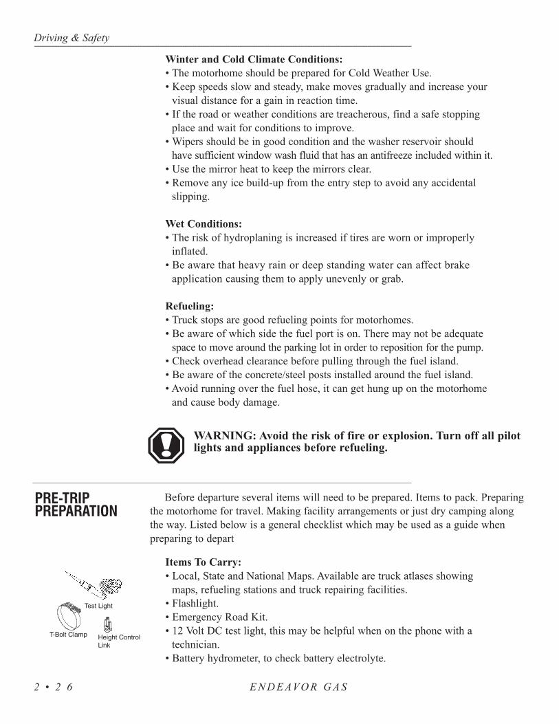
maps, refueling stations and truck repairing facilities.• Flashlight.• Emergency Road Kit.• 12 Volt DC test light, this may be helpful when on the phone with a
technician.• Battery hydrometer, to check battery electrolyte.
Driving & Safety----------------------------------------------------------------------------------------------------------------------------------------------------------------------------------------------------------------------------------------------------------------------------------------------------------------------------------
E N D E AVO R G A S2 • 2 6
PRE-TRIPPREPARATION

• An assortment of spare fuses.• A spare alternator belt.• A variety of assorted handtools.
Driving Preparations:• Check operation of all exterior lights, headlamp, taillight, brake
and clearance lights.• Inspect fluid level and check tire pressure.• Check house battery condition.• Secure all awning locks.• Check items in storage bays to prevent shifting or damage to items. • Outside compartment doors should be closed and locked.• Look around, above and under the motorhome for obstructions.• Check fuel level gauge. Check all other dash gauges for operation
and correct level indications.
Engine Checklist:• Inspect the engine, transmission and the engine compartment for
fluid leaks.• Inspect the area under the motorhome for fluid leaks or puddles.• Check all fluid levels, oil, antifreeze, transmission, hydraulic fluid
and washer fluid. • Inspect belts and hoses for wear.• Inspect wiring for loose, frayed or corroded connections.• Start engine and listen for any unusual noises.
Interior:• If possible, start refrigerator operation the night before departure
to get a head start on the cooling process. Pre-cool items prior toloading the refrigerator.
NOTE: While traveling, use the inverter to supply power tothe refrigerator. Upon arrival, be sure to turn the inverterOFF and switch refrigerator operation to LP-Gas or hookthe motorhome to shore power.
• Fill the fresh water tank. Disconnect and store the fresh water hose.• If necessary, load pots, pans, utensils, soap, linens, etc.• Secure and fasten the bi-fold and pocket doors. Lock the shower door.• Close roof vents and windows.• Secure any loose, heavy or sharp objects in case of a sudden stop.• Close all cabinet doors and drawers.• Walk the interior and check for items not secured.• Turn interior lighting off. • Secure and lock the entry door for travel.
Driving & Safety--------------------------------------------------------------------------------------------------------------------------------------------------------------------------------------------------------------------------------------------------------------------------------------------------------------------
E N D E AVO R G A S 2 • 2 7

When using the rear hitch remember that themotorhome is intended for towing light loads. Themotorhome is designed to be used primarily as arecreational vehicle, towing will affect durability andeconomy. Your safety and satisfaction require properuse. Avoid excessive loads or any other abuse. Donot use the motorhome to tow anything until it hasbeen driven 500 miles (800 kilometers). Weightpushing down on the rear hitch must not exceed 350pounds. We recommend weighing the motorhome asit will be operated to be certain that there is properweight distribution. When weighing the motorhome besure to take the passenger locations into consideration.Total weight of the motorhome and any vehicletowed by it must not exceed the GCWR.
WARNING: Any trailer being towed by a motorhome must haveadequate brakes. Failure to follow these instructions will create asafety hazard and may result in an accident.
The motorhome is prewired with a trailer wire harness. The harness is located on ornear the hitch receiver. Convoluted tubing protects the tow harness wires until they areready for use. Current draw should not exceed ten amps for each designated circuit.
The tow harness wires are color coded:1. Brown, 12 gauge - tail lights.2. White, 12 gauge - ground.3. Black, 14 gauge - right turn signal.4. Yellow, 14 gauge - left turn signal.5. Black w/white stripe, 14 gauge - brake light.
When hooking up a tow plug connection you should strip the wires 3/8”. Twistthe wire and place under the clip and secure the screw. Make sure there are no loosestrands of wire which could short against the case or other terminals.
The motorhome can be equipped with a rear vision and voice system. The factorywill provide the wiring behind the dash and at the rear cap for future installation.The rear vision system consists of a camera with a microphone and a monitor.
The driver can see what is behind the motorhome with the ability to listen to aguidance assistant. This is useful during backing procedures. The rear vision systemwill automatically turn ON when the gear selector is placed in reverse. Turning themain power switch to ON will allow continuous operation of the rear vision systemwhen the ignition key is turned ON.
For more detailed instructions see the manufacturer’s manual.
Driving & Safety----------------------------------------------------------------------------------------------------------------------------------------------------------------------------------------------------------------------------------------------------------------------------------------------------------------------------------
E N D E AVO R G A S2 • 2 8
HITCH - Using the Rear Receiver
Tow Plug Connection
REAR VIEWSYSTEM
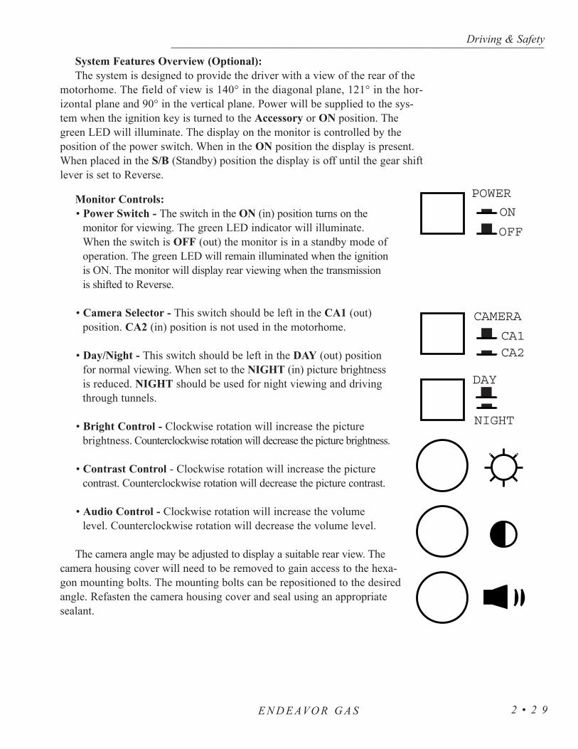
System Features Overview (Optional):The system is designed to provide the driver with a view of the rear of the
motorhome. The field of view is 140° in the diagonal plane, 121° in the hor-izontal plane and 90° in the vertical plane. Power will be supplied to the sys-tem when the ignition key is turned to the Accessory or ON position. Thegreen LED will illuminate. The display on the monitor is controlled by theposition of the power switch. When in the ON position the display is present.When placed in the S/B (Standby) position the display is off until the gear shiftlever is set to Reverse.
Monitor Controls:• Power Switch - The switch in the ON (in) position turns on the
monitor for viewing. The green LED indicator will illuminate.When the switch is OFF (out) the monitor is in a standby mode ofoperation. The green LED will remain illuminated when the ignitionis ON. The monitor will display rear viewing when the transmissionis shifted to Reverse.
• Camera Selector - This switch should be left in the CA1 (out)position. CA2 (in) position is not used in the motorhome.
• Day/Night - This switch should be left in the DAY (out) positionfor normal viewing. When set to the NIGHT (in) picture brightnessis reduced. NIGHT should be used for night viewing and drivingthrough tunnels.
• Bright Control - Clockwise rotation will increase the picturebrightness. Counterclockwise rotation will decrease the picture brightness.
• Contrast Control - Clockwise rotation will increase the picturecontrast. Counterclockwise rotation will decrease the picture contrast.
• Audio Control - Clockwise rotation will increase the volumelevel. Counterclockwise rotation will decrease the volume level.
The camera angle may be adjusted to display a suitable rear view. Thecamera housing cover will need to be removed to gain access to the hexa-gon mounting bolts. The mounting bolts can be repositioned to the desiredangle. Refasten the camera housing cover and seal using an appropriatesealant.
Driving & Safety--------------------------------------------------------------------------------------------------------------------------------------------------------------------------------------------------------------------------------------------------------------------------------------------------------------------
E N D E AVO R G A S 2 • 2 9
POWER
ON
OFF
CAMERA
CA1CA2
DAY
NIGHT
Whether you are a long time owner of recreational vehicles, or just starting out,backing up can be a challenge. Following some simple helpful guidelines may helpreduce the challenge. When backing up the driver (pilot) should be comfortableusing the mirrors, the back-up camera and the co-pilot’s directions (ground guide)for assistance. Practice first, backing up with the co-pilot’s guidance in a largeunobstructed parking lot. It is a team effort.
The backing up process should begin while the motorhome is in forward motion.Maneuver the motorhome to align it with the chosen site. This allows straightalignment with the site. Aligning the motorhome with the site after the backingprocess begins will require considerably more room than an automobile, and mayrequire more than one attempt. When the motorhome is properly aligned with thesite the parking area will be visible in both mirrors. Use straight lines, such as roadmarkings, as reference points when possible.
If the destination does not have “pull-through” sites, try to pick a solid, levelsite. If possible, pick a site located on the left side. This is the preferred side. Thedriver will have a better field of vision by using the driver side mirror. If the site ison the right side the driver will have to use the passenger side mirror for backing up,which leaves a blind spot. When a potential site is spotted stop the motorhomebefore the site. Get out and observe the area for soft ground, posts, large rocks, lowhanging limbs or other obstacles. If the site meets the particular criteria, prepare toback in carefully. Have the co-pilot guide you using the five hand signals.
The co-pilot will perform just as important a job as the driver. When guiding thedriver the co-pilot should be located safely at the left rear corner of the motorhome,facing forward, while remaining visible in the driver side mirror at all times. The co-pilot should make a conscious effort to maintain sight of the driver through the driv-er side mirror as the front of the motorhome maneuvers. If the driver loses sight ofthe co-pilot stop the backing up process until the co-pilot returns to view. To avoidmishaps the co-pilot should be focused only on what the driver is doing, with briefobservation moments. The driver should receive directions only from the co-pilot. Ifnecessary, stop the backing up process to have co-pilot inspect other areas or anglesof concern. Use of walkie-talkies will aid in guidance.
When co-pilot is guiding the driver, only five clearly defined signals should beused with only one signal given at a time. Flailing arms with indecisive signals onlyconfuse the driver. Signals should be given with purpose and confidence. Directionalsignals are directing travel of the rear of the motorhome.
If desired direction is left, the co-pilot points left. For example: The co-pilot willuse his/her right arm and forefinger pointing distinctly left with arm and finger heldon a horizontal plane, indicating desired direction of travel of the rear of themotorhome. This type of directional signal is easily discerned in the mirror by thedriver. The directional signal given will remain steady until desired movement iscompleted.
Driving & Safety----------------------------------------------------------------------------------------------------------------------------------------------------------------------------------------------------------------------------------------------------------------------------------------------------------------------------------
E N D E AVO R G A S2 • 3 0
BACKING UPA MOTORHOME

The five directional signals are:1. Co-pilot uses left hand and arm held horizontal with forefinger
pointing right to direct rear of motorhome to the right. 2. Co-pilot uses right hand and arm held horizontal, with forefinger
pointing left to direct rear of motorhome to the left.3. Co-pilot uses both arms and hands parallel with thumbs pointing
up and to rear in a waving vertical motion. This signals driver to maintain a straight back direction.
4. Co-pilot holds arms vertically, hands open with palms facing one another. Start with a wide separation, gradually closing distance of hands, in a rate appropriate to vehicle speed to indicate amount of distance to stop point.
5. Closed fists indicates STOP.
Backing Up Trailers:Trailers have only one pivot point. Trailers may be backed up.
Towed vehicles using a tow bar or tow dolly have more than one piv-oting point which makes this type of equipment not suitable for backing. If usingthis type of towing equipment, plan ahead. Park safely along the road and walk adistance if necessary to avoid a possible back up situation. Avoid putting themotorhome and tow vehicle in a backing situation. To back up this combinationcompletely disconnect the tow vehicle from motorhome. Trying to back up themotorhome with a tow vehicle connected will result in damage to the motorhome,tow vehicle and towing device.
The same rules for backing a motorhome may be applied when backing atrailer. When preparing to back a trailer into a space maneuver the motorhomesweeping wide, then turn back to the opposite direction. This will set themotorhome and trailer in a position to maneuver the trailer into space. Whenbacking a trailer the driver may become disoriented with the direction of thesteering wheel and the direction of the trailer. The bottom of the steering wheelmust be moved in the desired direction of the trailer. For example: If thedesired direction of the trailer is left, rotate the bottom of the steering wheelleft. If the trailer moves in an undesired direction, use a short “pull-up”method, pulling forward just far enough to align the trailer with the space. Theco-pilot should stand safely at the left rear corner of the trailer within view ofthe driver in the driver side mirror using the five hand signals for guiding.
The motorhome parking brake is a foot pedal brake which operates in thesame manner as an automobile parking brake. When at a complete stop, select“P” on the shift lever, then engage the foot pedal brake. The brake is releasedby the “brake release” handle, located below the lower left area of the dash.
Driving & Safety--------------------------------------------------------------------------------------------------------------------------------------------------------------------------------------------------------------------------------------------------------------------------------------------------------------------
E N D E AVO R G A S 2 • 3 1
Brake - Parking

CAUTION: Tow bars or car dollies generally are made to travelin a forward direction only. Most towing equipment of this typeis not designed for backing. Never attempt short back up dis-tances with a tow bar or tow dolly. Damage to the motorhome,vehicle or towing device will result.
The leveling system is designed as a leveling system only. The leveling systemshould not be used to support the motorhome while under coach or for changingtires. A tire change should be performed by trained personnel with the proper toolsand equipment. Attempts to change tires using the leveling jack to support themotorhome could result in damage to the motorhome and risk causing seriouspersonal injury.
The leveling system shall only be operated under the following conditions:
• The motorhome is parked on a reasonable level surface.• The PARKING BRAKE must be engaged.• The transmission must be in the NEUTRAL or PARK position.• The ignition switch is placed in the IGN position.
Ensure the potential jack contact points are clear of obstructions or depressionsbefore operation.
Keep all people clear of the motorhome during the leveling system operations.Never expose hands or other parts of the body near hydraulic leaks. Hydraulic linesare under high pressure. Oil leaks may cut and penetrate the skin causing seriousinjury.
• To level motorhome turn ignition switch to ACC or ON position.
• Transmission shift lever must be in park position and parkingbrake must be set. If “NOT IN PARK/BRAKE” indicatorlight is lit check that shift lever and parking brake are intheir proper positions.
• Push ON button, ON indicator light should be lit.• Move FRONT and REAR JACKS LEVERS to OPERATE
positions.• Move RAISE MOTORHOME LEVER to raise rear of motor-
home slightly so that both rear jacks contact the ground; do not extend jacks all the way.
• Move RAISE MOTORHOME LEVER to raise front of motorhome slightly so that both front jacks contact the ground; do not extend jacks all the way. If yellow indicator light on any arrow is lit, move RAISE MOTORHOME
Driving & Safety----------------------------------------------------------------------------------------------------------------------------------------------------------------------------------------------------------------------------------------------------------------------------------------------------------------------------------
E N D E AVO R G A S2 • 3 2
LEVELING SYSTEM (Optional)
Before Operations ofthe Leveling Jacks
Leveling the Motorhome

LEVER in direction of arrow until light goes out.• If ground is too uneven jacks may not have enough stroke to level
motorhome, therefore motorhome may have to be moved to another loca-tion.
• After motorhome is level push OFF button and turn ignition switch to OFF position.
• To store leveling jacks turn ignition switch to ACC or ON position.• Move FRONT and REAR JACKS LEVERS to STORE positions; all jacks
should raise all the way up. All four red indicator lights should not be lit and warning buzzer should not be sounding.
• After jacks have been retracted push OFF button and turn ignition switchto OFF position.
• If the jacks are down for extended periods, it is recommended to spray exposed chrome with a automatic transmission fluid (A.T.F.) every sevendays for protection.
In most applications, the Type A automatic transmission fluid is adequate. Ifoperating in cold temperature (less than 10-F°) the jacks may extend andretract at a slower rate.
WARNING: Never rely solely upon warning lights or warn-ing buzzer to determine position of leveling jacks. Make avisual to check to ensure all jacks are fully retracted prior tomoving the motorhome.
If the site for the motorhome has full hook-ups, use this quick referencehook-up checklist. This hook-up list is only a guide. For detailed information lookin the section pertaining to the item of interest.
• Prepare the shore cord to be plugged in. Uncoil and inspect thecord. Perform any necessary cord maintenance. Install proper elec-trical adapters if anything other than 50 amp service is provided.Turn power supply circuit breaker off before plugging in the shorecord.
• If cable service is provided, hook a 75 Ohm or RG6 cable to thecable connection in the service center. If the motorhome has avideo selector box, press the CABLE VIEW button for itemdesired.
• A phone jack hook-up is provided in the service center. Phone out-lets are placed throughout the motorhome, including a phone lineto the satellite receiver.
Driving & Safety--------------------------------------------------------------------------------------------------------------------------------------------------------------------------------------------------------------------------------------------------------------------------------------------------------------------
E N D E AVO R G A S 2 • 3 3
Retract the Leveling Jacks
CHECKLIST -SET-UP
PROCEDURES

• Hook a potable water hose to the city water connection in the servicecenter. A water pressure regulator is built in. Turn the hand valve so thepointer indicates CITY WATER.
• Sewer drain pipe diameters are generally either three or four inches.Proper sewer hose adapters will ensure against leaks or spillage. Withthe sewer hose properly connected, open the grey water valve (smallvalve). The black water valve (large valve) remains closed until the tankis full or until time of departure.
NOTE: When dumping the black tank, first close the grey watervalve and fill the tank 50%. Open black tank valve until the draincycle is complete. Use a non-potable water hose when using theblack tank flush system. Close the black tank valve, then openthe grey water valve. Solids will be flushed from the drain hose.
Driving & Safety----------------------------------------------------------------------------------------------------------------------------------------------------------------------------------------------------------------------------------------------------------------------------------------------------------------------------------
E N D E AVO R G A S2 • 3 4
For extended dry camping, management of all resources is essential. Themotorhome has large batteries, plenty of water and large holding tank capaci-ties. With a little care and forethought it is possible to go a long way with onlythe wonderful amenities you bring with you.
Conserve water! The motorhome holds a lot but it goes down the drain fast.Use a manual valve on the shower head. Turn the water off and on as neededwhile showering. By doing this the amount of water needed for a shower canbe reduced by as much as two-thirds. Don't let water run in sink while doingother things such as wiping up the kitchen counters or brushing your teeth.
Conserve battery power. Use electricity sparingly. Turn off the inverterwhen it is not in use. Only turn it on when you need it. However, rememberthat when the generator is running the inverter will come on automatically.
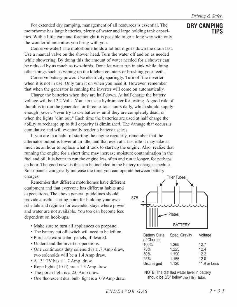
Charge the batteries when they are half down. At half charge the batteryvoltage will be 12.2 Volts. You can use a hydrometer for testing. A good rule ofthumb is to run the generator for three to four hours daily, which should supplyenough power. Never try to use batteries until they are completely dead, orwhen the lights "dim out." Each time the batteries are used at half charge theability to recharge up to full capacity is diminished. The damage that occurs iscumulative and will eventually render a battery useless.
If you are in a habit of starting the engine regularly, remember that thealternator output is lower at an idle, and that even at a fast idle it may take asmuch as an hour to replace what it took to start up the engine. Also, realize thatrunning the engine for a short time may increase moisture contamination in thefuel and oil. It is better to run the engine less often and run it longer, for perhapsan hour. The good news is this can be included in the battery recharge schedule.Solar panels can greatly increase the time you can operate between batterycharges.
Remember that different motorhomes have differentequipment and that everyone has different habits andexpectations. The above general guidelines shouldprovide a useful starting point for building your ownschedule and regimen for extended stays where powerand water are not available. You too can become lessdependent on hook-ups.
• Make sure to turn all appliances on propane.• The battery cut off switch will need to be left on.• Purchase extra solar panels, if desired.• Understand the inverter operations.• One continuous duty solenoid is a .7 Amp draw,
two solenoids will be a 1.4 Amp draw.• A 13" TV has a 1.7 Amp draw.• Rope lights (10 ft) are a 1.3 Amp draw.• The porch light is a 2.0 Amp draw.• One fluorescent dual bulb light is a 0.9 Amp draw.
Driving & Safety--------------------------------------------------------------------------------------------------------------------------------------------------------------------------------------------------------------------------------------------------------------------------------------------------------------------
E N D E AVO R G A S 2 • 3 5
DRY CAMPINGTIPS

Listed below is a checklist guide to reference when preparing to break camp.Preparing the motorhome for travel will require several small tasks. Items properlysecured and stowed will help prevent items from getting lost or being damagedduring travel.
Outside Checklist:• Disconnect the cable TV, lower the television antenna and (if applicable)
the satellite dish.• Retract the awnings and secure them for travel.• Close LP-Gas tank valve. Check the level of the LP-Gas in the tank
making sure there will be a sufficient amount.• Drain and flush the holding tanks. First close the grey water valve, run
enough cold water down the sink and shower drains until the grey tankis at least 50% full. Be careful not to overfill or flood the grey tank.Next, open the black tank valve and allow the drain cycle to complete.If applicable, connect a non-potable water hose to the No-Fuss hose biband flush the black tank system. Close the black tank valve, then openthe grey water valve. The water from the grey tank will help flush thesolids from the drain hose.
• Disconnect the sewer hose. Flush hose with clean water from non-potable hose. Store the hose. Install the sewer cap.
• Fill the fresh water tank. Disconnect and store the fresh water hose.Remove any hose protected water pressure regulator from the city waterfaucet.
• Turn shore power breaker off and disconnect the shore line. Wind upand store the shore cord.
• Disconnect and stow the phone line.• Check tire pressure.
Engine Checklist:• Inspect the engine, transmission and the engine compartment for fluid
leaks.• Inspect the area under the motorhome for fluid leaks or puddles.• Check all fluid levels, oil, antifreeze, transmission, hydraulic fluid and
washer fluid. • Inspect belts and hoses for wear.• Inspect wiring for loose, frayed or corroded connections.• Start engine and listen for any unusual noises.
Interior Checklist:• If applicable, retract leveling jacks.• If applicable, clear slide room path, clean floor, move the driver seat
forward and make sure bay doors are shut. When the slide room is fullyretracted secure slide room awning locks for travel.
Driving & Safety----------------------------------------------------------------------------------------------------------------------------------------------------------------------------------------------------------------------------------------------------------------------------------------------------------------------------------
E N D E AVO R G A S2 • 3 6
BREAKING CAMP

NOTE: To operate the kitchen slide the ignition must beOFF, the park brake must be set and the bay doors underthe slide room must be closed.
• Secure and fasten the bi-fold and pocket doors. Lock the shower door.• Close roof vents and windows.• Secure any loose, heavy or sharp objects in case of a sudden stop.• Close all cabinet doors and drawers.• Start engine, turn off water heater, water pump and furnace. If
applicable, turn inverter ON. Switch refrigerator operation to electric.Be sure to turn inverter OFF and switch refrigerator operation backto LP-Gas or hook the motorhome to shore power upon arrival.
Departure Checklist:• Check items in storage bays to make sure shifting or damage of
items won’t occur.• Look around, above and under the motorhome for any obstructions.• Walk around the motorhome and camp area checking for forgotten items.• Outside compartment doors should be closed and locked.• Check operation of all exterior lights - headlamp, tail lamp, brake
and clearance lights.• Walk the interior and check for any items not secured.• Turn interior lighting off. • Check fuel level gauge. Check all other dash gauges for operation
and correct level indications.• Carefully pull forward out of campsite. If necessary, clean site and
check for any forgotten items.• Secure and lock the entry door for travel.
Emergency stops may be required for any number of reasons. Proper brakingtechniques should be used during an emergency stop. An emergency road kitshould include three reflective warning signs, road flares, a flashlight, spareautomotive fuses and an assortment of hand tools. For added safety an extrafire extinguisher should also be included. The motorhome is equipped with afire extinguisher located inside next to the co-pilot seat. Road flares or a reflectivewarning sign should be displayed if you are along the side of the road for anylength of time. Pull off the roadway as far as possible for an emergency stop.Always turn ON the motorhome’s hazard warning flasher when parked alongthe side of traffic lanes. Set the parking brake. In the event of an emergencystop, for a mechanical or motorhome related problems, contact HolidayRambler Customer Service Support (1-877-466-6226).
Guidelines for placing the warning triangles depends on the road. On adivided highway or one way road the placement is 10 feet, 100 feet and 200feet from the rear of the motorhome. On a two lane road the placement should
Driving & Safety--------------------------------------------------------------------------------------------------------------------------------------------------------------------------------------------------------------------------------------------------------------------------------------------------------------------
E N D E AVO R G A S 2 • 3 7
EMERGENCYPROCEDURES

be 10 feet either front or rear of the motorhome and 100 feet in both directions ofthe motorhome. Curves and hills can be tricky as you may have to go up to 500 feetbehind the motorhome to warn approaching traffic after placing one triangle 10 feetfrom the rear.
1. To activate the light move the switch to the ON position. 2. The light has an 18 foot retractable reel cord. To operate the
reel lift the lever and pull the light out.3. The base of the light is magnetic, allowing for hands-free operation.4. To replace the bulb push down on the clear plastic cover and twist.5. To rewind the light crank the handle in the retract direction. When
fully retracted push down on the lock handle to secure the light into place.
It may be possible to rock the motorhome out if you are stuck in snow, mud ordeep sand. Shift the selector to D (Drive) and apply steady light throttle. Neverapply full throttle as you may spin the wheels and bury the motorhome deeper.When the motorhome has moved forward as far it will go apply and hold the servicebrakes. Allow the engine to return to idle before selecting the R (Reverse). Releasethe brake and apply light throttle until the motorhome has rocked as far it will go.Again, apply the service brake and allow the engine to return to idle. Repeat thisprocess if the motorhome has moved a greater distance. If the process does not freethe motorhome call for towing assistance.
NOTE: Sudden movements or lurching the motorhome with anopen throttle can result in damage to the transmission. Avoid thiscondition by making shifts only when the throttle is closed andengine is at normal idle.
If a towing company is called for service it is recommended that they use alowboy/landall type of trailer and if a tow truck is used it needs to have a stinger(an arm that goes under motorhome and hooks to front cross member). Inform thetow company of the weight and length of the motorhome, number of passengers andmilepost location. If the motorhome ever needs to be towed, use the followingdirections:
• Secure any loose or protruding parts if the motorhome is damaged.• Inspect points of attachment on a disabled motorhome. If attachment
points are damaged, select other attachment points at a substantial framestructural member.
Driving & Safety----------------------------------------------------------------------------------------------------------------------------------------------------------------------------------------------------------------------------------------------------------------------------------------------------------------------------------
E N D E AVO R G A S2 • 3 8
Light - Retractable
Transmission -Rocking Out
TOWINGPROCEDURES

• Never allow anyone to go under a motorhome while it is beinglifted by towing equipment unless the disabled motorhome is ade-quately supported by safety stands.
• Do not tow the motorhome from the rear. Towing from the rearwill cause the front tires and suspension to be seriously overloaded,possibly resulting in a tire or front suspension failure. Rear frameextensions are not designed to withstand weight loads imposed bylifting the rear of the motorhome.
• If rear wheels are disabled place the motorhome on a flat bed trail-er or use a heavy duty dolly under the rear wheels and tow fromthe front of the motorhome.
• The drive shaft must be removed to prevent damage to thetransmission.
WARNING: In the event the motorhome requires towingensure all precautions are followed. The driveline must bedisconnected and the mudflap may need to be removed.Damage to the motorhome from a towing company will notbe covered by Holiday Rambler.
Make sure the tow truck can safely pull the weight of the motorhome. Givethe towing company the weight of the motorhome when you call them. If themotorhome is going to be towed without a stinger do the following:
• Wrap chains around both A-arms or the front axle on each side.• Pass the chains beneath the tow bar below the bumper.• Position a 6" x 6" piece of lumber between the ends of main frame
rails and the tow vehicle transfer plate to maintain clearance tobody parts.
• Attach safety chains, which are completely independent of theprimary lifting device, to the main frame rails.
• When the motorhome is under tow, allow enough room betweenthe front of the motorhome and the rear of the tow vehicle whileturning corners.
The tire designed for the RV is a very technical and precisely engineeredproduct. To obtain the maximum use and best service out of the tires it is helpfulto understand the function of a tire. A tire is a “container” that holds air. It isthe combination of air and tire that supports the motorhome and its contents. Inaddition, since the tire is the only contact that the motorhome has with the roadsurface, it must provide other functions such as traction for moving, stopping,steering and providing a cushion for the motorhome.
Driving & Safety--------------------------------------------------------------------------------------------------------------------------------------------------------------------------------------------------------------------------------------------------------------------------------------------------------------------
E N D E AVO R G A S 2 • 3 9
Towing Without A Stinger
TIRES

Driving & Safety----------------------------------------------------------------------------------------------------------------------------------------------------------------------------------------------------------------------------------------------------------------------------------------------------------------------------------
E N D E AVO R G A S2 • 4 0
The most important factor in maximizing the life of the tires is maintaining properinflation. Driving on tires that do not have the correct inflation pressure for the loadof the motorhome is dangerous and may cause premature wear, tire damage and/orloss of control of the motorhome.
A tire that is underinflated will build up excessive heat that may go beyond thedesign limits of the rubber and radial cords. This could result in sudden failure. A tirethat is underinflated will also cause poor motorhome handling, rapid and/or irregular tirewear and an increase in rolling resistance which results in a decrease of fuel economy.
Over-inflation will reduce the tire’s “footprint” or contact patch with the road,thus reducing traction, braking capacity and handling of the motorhome. A tire thatis over-inflated for the load will have a harsh ride, uneven tire wear and becomessusceptible to impact damage.
Maintaining correct tire inflation pressure for each loaded wheel position on themotorhome is of the utmost importance and must be a part of regular motorhomemaintenance.
Federal law requires that the tire’s maximum load rating be molded into the side-wall of the tire. If you look on your tire’s sidewall, you will see the maximum loadallowed for the size tire and loading rating, and the minimum cold air inflation pres-sure needed to carry that stated maximum load. Utilizing less air pressure means alesser load can be carried by the tire. The chart at the end of the sections showsweights that can be supported by various air pressures.The amount of air pressure you need to use is dependent on the weight of your fullyloaded motorhome.
The GVWR (Gross Vehicle Weight Rating) and GAWR (Gross Axle WeightRating) stickers on the motorhome (normally located on the support pillar next tothe driver’s seat) will show the chassis manufacturer’s and/or the RV manufacturer’stotal vehicle maximum weight ratings and per axle weight rating.
The GVWR is the maximum total weight for which the motorhome is rated-including passengers, fluids, and cargo.
The GAWR is the maximum for which a single axle is designed. These per axleand total maximum weight ratings could be limited by the tires, wheels, axle andaxle bearings, the motorhome frame or other components of the motorhome.
The GAWR sticker is only a guide in knowing the maximum loaded axleweights, and subsequently the correct tire inflation pressure. Every RV, even of thesame make and model, will vary in actual loaded axle weights because of differentoptions and personal loads.
While the actual loaded axle weight should be below the GAWR, you mustweigh your motorhome in a loaded condition to know its actual weight. Weigh thefront axle, the total unit and the rear axle. It is possible for a motorhome to be withinthe GVWR yet overloaded on an axle. It is even possible for one wheel position tobe overloaded, even though the GAWR has not been exceeded. For this reason (if
The Importance of Air Pressure
How Much Air Pressure?
Weight Terms

Driving & Safety--------------------------------------------------------------------------------------------------------------------------------------------------------------------------------------------------------------------------------------------------------------------------------------------------------------------
E N D E AVO R G A S 2 • 4 1
there is room to the sides of the scales) weigh each wheel position of themotorhome. This will give a clear indication of exactly how the weight ofthe motorhome is distributed. These instructions and diagrams are presented onthe following pages. When the total weight and the weight on each axle isknown, the tire load data chart in this manual will show you the correct cold infla-tion pressure per tire for each axle.
There are two important factors to consider when loading the motorhome:total weight and balance. When loading heavy objects keep them as low aspossible, preferably on the floor. Load weight must be distributed as evenly aspossible. Listed below are the commonly used weight abbreviations and terms.
• Gross Vehicle Weight Rating (GVWR): GVWR means maximum permissible weight of this motorhome.GVWR is equal to or greater than the sum of UVW plus NCC.
• Unloaded Vehicle Weight (UVW):UVW means weight of this motorhome as built at factory with fullfuel, engine oil and coolants. UVW does not include cargo,fresh water, LP-Gas, occupants or dealer installed accessories.
• Net Carrying Capacity (NCC):NCC means maximum weight of all occupants including driver,personal belongings, food, fresh water, LP-Gas, tools, tongueweight of towed vehicle, dealer installed accessories, etc., that canbe carried by this motorhome. (NCC is equal to or less thanGVWR minus UVW.)
• Gross Combination Weight Rating (GCWR):GCWR means value specified by motorhome manufacturer asmaximum allowable loaded weight of this motorhome with itstowed trailer or towed vehicle.
• Gross Axle Weight Rating (GAWR):GAWR means load-carrying capacity specified by manufacturer ofa single axle system as measured at tire ground interfaces.
• Sleeping Capacity Weight Rating:SCWR means manufacturers designated number of sleeping posi-tions multiplied by 154 pounds (70 kilograms).
• Cargo Carrying Capacity (CCC):CCC means the GVWR minus each of the following: UVW, fullfresh (potable) water weight (including water heater), full LP-Gasweight and SCWR.

Driving & Safety----------------------------------------------------------------------------------------------------------------------------------------------------------------------------------------------------------------------------------------------------------------------------------------------------------------------------------
E N D E AVO R G A S2 • 4 2
LBS. KGS.
MODEL YEAR: 2001 MAKE: HOLIDAY RAMBLER MODEL: ENDEAVOR GAS
UNIT NO. ______________ CHASSIS VIN: ___________________________________
GVWR (Gross Vehicle Weight Rating) is the maximum permissible weight of this fully loaded motorhome .....................
UVW (Unloaded Vehicle Weight) is the weight of an exemplar Motorhome as manufactured at the factorywith full fuel, engine oil and coolants (*1) ...................................
SCWR (Sleeping Capacity Weight Rating) is the manufacturer’sdesignated number of sleeping positions multiplied by 154 pounds (70 kilograms) .........................................................
CCC (Cargo Carrying Capacity) is the GVWR minus each ofthe following: UVW, full fresh (potable) water weight
(including water heater), full LP-Gas weight and SCWR............
GCWR (Gross Combination Weight Rating) is the maximum allowable combined weight of this motorhome and any towed vehicle (*2).
CARGO CARRYING CAPACITY (CCC) COMPUTATIONGVWR ...............................................................................................................
minus UVW ...........................................................................................minus fresh water (*3) weight of gallons @ 8.3 lbs./gal ...............minus LP-Gas weight of gallons@ 4.5 lbs./gal ..............................
CCC for this motorhome (*4) ............................................................................
CONSULT OWNER MANUAL(S) FOR SPECIFIC WEIGHING INSTRUCTIONS ANDTOWING GUIDELINES.
Factory installed options do not include dealer installed after market equipment.
WARNING:DO NOT EXCEED THE GVWR, GCWR AND/OR GAWR AFTER LOAD-ING YOUR MOTORHOME WITH WATER, FUEL, PASSENGERS AND CARGO.GAWR (Gross Axle Weight Rating) means the maximum permissible load weighta specific axle is designed to carry. See Federal Certification Label for disclosureof The GAWR for each axle.
(*1) The UVW has been determined by weighing an exemplar motorhome with some but not alloptional equipment available for each model year, make and model of motorhome. The result ofthe weighing of the exemplar motorhome is then used in calculating the UVW of othermotorhomes of same model year, make and model. Your actual UVW may vary based uponoptions ordered. Please contact the manufacturer of the actual weight of each option.(*2) Consult your Owner’s Manual for towing limitations, restrictions and other guidelines.(*3) Your motorhome’s fresh water tank and water heater taken together determine the grossfresh water capacity. Your usable fresh water capacity, however, may be less.(*4) Dealer installed equipment and towed vehicle tongue weight will reduce CCC.

Improperly inflated tires or suspension that is incorrectly loaded can resultin poor fuel economy, poor handling and over stressed chassis components.Vehicle loading affects tire inflation pressure and the loads carried by eachaxle. Motorhome axle configuration and floor plan styles will require differentweighing procedures.
WARNING: Improperly inflated or overloaded tires cancause a blowout. An overloaded axle can cause a componentfailure of the suspension system. Tire blowouts or brokensuspension components can lead to loss of vehicle controlresulting in property damage, personal injury or death.
CAUTION: If actual weight carried by any tire is below thetire chart weight specification, a minimum tire pressure of atleast 75 psi. must be maintained. Tire pressure below 75 psi.can overheat and damage the tire casing leading to prema-ture tire failure or blowout.
Slide-Out Tire Pressure:A motorhome equipped with slide-out room(s) will weigh slightly heavier
on the driver side. Tire inflation pressures between the driver side and passen-ger side will differ. More air pressure will be required in the driver side tiresdue to the added weight on that side.
NOTE: When weighing a slide out motorhome, each tiremust be weighed independently to obtain the correct weightcarried by each tire.
Scales:Certified public scales are located in a variety of places such as moving and
storage lots, farm suppliers with grain elevators, gravel pits, recycling companiesand large commercial truck stops.
If you are not aware of a nearby public scale check the local area telephonebook yellow pages under “scales-public” section or “weighers.” A nominal feewill be charged, but this is money wisely spent.
Weight scale types and weighing methods will affect the procedure used todetermine proper tire inflation pressure and axle loading. The size of somescales will allow the entire motorhome to fit on the scale, which will read theGVW with only one scale recording required. Other scales are designed toweigh only one axle at a time, which may require two or three scale readingsto determine the GAW or GVW total. Some scales will read only one wheelposition at a time due their physical size. Several scale readings may berequired to determine the GAW or GVW total.
Slide-out equipped motorhomes will require each wheel position to beweighed. This is referred to as a four corner weigh. This type of weighing pro-cedure will accurately determine what the correct tire inflation pressure shouldbe. Depending on the type of scale being used, several different scale readingsmay be required.
Driving & Safety--------------------------------------------------------------------------------------------------------------------------------------------------------------------------------------------------------------------------------------------------------------------------------------------------------------------
E N D E AVO R G A S 2 • 4 3

NOTE: The most accurate method to determine proper tire pres-sure is a four corner weigh. A slide-out motorhome will requireeach tire to be weighed independently. Weighing an axle will netthe total weight carried by that axle. When calculating the driveaxle dual tire pressure using a independent corner weigh method,divide the total weight by two to determine the weight carried byeach tire. When weighing the entire drive axle, divide the totalweight by four to determine the approximate weight carried byeach tire.
Example:The motorhome must be weighed fully loaded to obtain accurate scale readings
and to determine the proper tire pressure.
• Take the rear axle gross axle weight rating (GAWR) anddivide it by two. Record the figure next to scale B GAWR ÷2. Example: If rear axle GAWR is 13,000 lbs. GAWR ÷ 2would be 6,500 lbs.
• Weigh the driver’s side rear corner (scale B) and record thescale reading next to gross axle weight (GAW) for scale B.Example: Scale B reading is 5100 lbs.
• Repeat procedure for the rest of the scale readings.• Add the GAWR from scales B and D and enter the sum next
to the final GAWR. Example 13,000. • Add the GAW from scales B and D and enter this sum next
to the final GCAW. Example: 10,000.• Compare scale readings GCAW against GAWR readings. All
figures on line 2 are not to exceed figures on line 1. • Use tire chart with scale reading to determine correct tire
pressure.
NOTE: Scale readings and gross axle weight rat-ings are fictitious. Actual scale readings and grossaxle weight ratings will vary with model andoptions.
Driving & Safety----------------------------------------------------------------------------------------------------------------------------------------------------------------------------------------------------------------------------------------------------------------------------------------------------------------------------------
E N D E AVO R G A S2 • 4 4
1.GAWR ÷ 2 (6,500)2.GAW (5100)
+
1. GAWR ÷ 2 (6,500)2. GAW (4,900)
ScaleB
ScaleD
= 2. GCAW (10,000)1.GAWR (13,000)
Rear
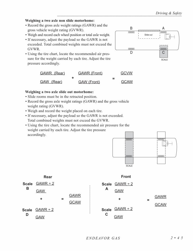
Weighing a two axle non slide motorhome:• Record the gross axle weight ratings (GAWR) and the
gross vehicle weight rating (GVWR).• Weigh and record each wheel position or total axle weight.• If necessary, adjust the payload so the GAWR is not
exceeded. Total combined weights must not exceed theGVWR.
• Using the tire chart, locate the recommended air pres-sure for the weight carried by each tire. Adjust the tirepressure accordingly.
Weighing a two axle slide out motorhome:• Slide rooms must be in the retracted position.• Record the gross axle weight ratings (GAWR) and the gross vehicle
weight rating (GVWR).• Weigh and record the weight placed on each tire. • If necessary, adjust the payload so the GAWR is not exceeded.
Total combined weights must not exceed the GVWR.• Using the tire chart, locate the recommended air pressure for the
weight carried by each tire. Adjust the tire pressureaccordingly.
Driving & Safety--------------------------------------------------------------------------------------------------------------------------------------------------------------------------------------------------------------------------------------------------------------------------------------------------------------------
E N D E AVO R G A S 2 • 4 5
GAWR (Rear) GAWR (Front)
GAW (Front)GAW (Rear)=
GCAW
GCVW+
GAWR ÷ 2 GAWR ÷ 2
GAWGAW
+
GAWR ÷ 2 GAWR ÷ 2
GAWGAW
+ =GCAW
GAWR
ScaleB
ScaleC
ScaleA
ScaleD
=GCAW
GAWR
Rear Front

Use the tire chart to locate the recommended air pressure for the weight car-ried by each tire. A quality truck tire gauge with an angle dual head is recom-mended. Adjust the tire pressure accordingly.
Driving & Safety----------------------------------------------------------------------------------------------------------------------------------------------------------------------------------------------------------------------------------------------------------------------------------------------------------------------------------
2 • 4 6
TIRESIZE
8R19.5
225/70R19.5
245/70R19.5
265/70R19.5
9R22.5
10R22.5
11R22.5
12R22.5
245/75R22.5
255/70R22.5
265/75R22.5
275/80R22.5
295/75R22.5
295/80R22.5
315/80R22.5
285/75R24.5
MAXSpeedRating(MPH)
75
75
75
75
65
65
75
65
75
75
75
75
75
75
75
75
Dual (D)
Single(S)
DSDSDSDSDSDSDS
DSDSDS
DS
DS
DS
DSDSDS
65
23502410
31203190
36903770
702460254027202895
34153640
32703370
38704000
32603470
35853815
752570268028603040
35153740
34103560
40404210
34253645
37654005
40404070
46904725
47404770
802680280030003195
36553890
3750397035503730
4200441047604990
51905450
36403860
39704190
42054255
48854945
48555480
49304990
852780293031153315
3875(F)4080(F)
3930418036903890
4375461049505220
53905690
37403980
41104370
43704440
48555265
50705155
51005750
5840641552055210
902880306032453450
39404190
4095435538204050
45204790
51205430
55905920
38904140
42754550
45254620
50805515
52605370
53356020
6070667053105420
9529803170
3415(F)3640(F)
40754335
43004540
3950(F)4210
46704970
53005640
57806140
40804300
44104675
46854800
53055755
54405510
55706285
6395694054955675
10030703280
4375(G)4545(G)
44054685
4350
4875(F)5150(F)
54705840
59606370
41904455
44554895
4805(G)4975
55256000
5675(G)5780
5805655065407190
5675(G)5835
10531603400
45604850
4500(F)
49705320
5750(G)6175(G)
61506590
43354610
46105065
5150
57456235
58005980
6035681067707440
6040
1103375(F)3500(F)
48055070
51105490
5800(H)6240
63206790
4410(G)4675(G)
46755205
5205(G)
59656475
6005(H)6175(G)
6265707069407610
6175(G)
115
48605170
5250(G)5680(G)
6430
65007010
5070(H)5510(H)
61806710
63706490732072107920
120
5070(G)5355(G)
6610(H)
6750(H)7390(H)
6395(H)6940(H)
6610(H)67207580
7610(J)8270(J)
125
6940(H)7830(H)
I N F L AT I O N P R E S S U R E
-
P S I
Chart - Tire Inflation
E N D E AVO R G A S
Holiday Rambler is not the author of this chart and makes no representation orwarranty concerning the accuracy of the information disclosed by the chart. HolidayRambler is not responsible for the accuracy of the information disclosed or for anyerrors within the Tire Inflation Chart.

Check the tire pressure regularly. If a tire is punctured by a nail or screw,creating a slow leak, it may eventually be spotted if it is a front tire or an outsiderear dual. However, if there is a leak on an inside dual the chances of spottingit without an air pressure check are very slim. If you begin driving unawarethat an inside dual tire has a low air pressure or is flat, very quickly (in mostcases a few miles) the outside rear tire (next to the low air pressure tire) willheat up from carrying double the load, leading to failure of the outside dualtire. The motorhome will end up with two tires flat on the same side on thesame axle.
The air pressure should be checked every two weeks or at least once amonth and before any major trip. The RV tire air pressure should be checkedevery “drive” morning on both long and short trips (driving a day or less). Thetires should be checked before leaving on a trip and again before you start yourtrip home. If the motorhome is stored for any length of time the air pressureshould be checked prior to storage. More importantly, check the tire pressurewhen it is pulled out of storage.
Check the tire pressure when the tires are “cold” and have not been drivenfor more than one mile. The stated load capacity for a given cold inflationpressure is based on ambient outside temperature. If you must check the tireswhen they are warm or hot, allow for a slight increase in air pressure and makesure they are within a couple of pounds of each other on the same axle (doesnot apply to slide-out equipped motorhomes). Never let air out of a hot tire.
To check or maintain the inflation pressure in the tires use a quality trucktire air gauge which has an angle dual head. This type of gauge will allow youto check inflation of the inner dual wheel which has the valve stem pointingoutward; the outer wheel which has the valve stem pointing inward. Nothingshould restrict the ability to check the tire’s air pressure daily when traveling inthe motorhome. Pressure sealing valve caps should always be used to preventair from escaping from the valve stem. If there are valve stem extension hosesmake sure they are good quality stainless steel braid reinforced and are securelyanchored to the outer wheel.
Optimum tire performance is achieved with proper inflation pressures forthe loads being carried. The air pressure of all tires should be checked andcorrected prior to travel, or daily if in full time use.
Tires of different patterns should not be mixed on the same axle. Thedifference in tractive force could cause rear end gear fight and mechanicaldamage to the drive train. Tires of different size or construction must never bemixed on the same axle.
Higher than recommended pressure can cause:• Hard ride.• Tire bruising or carcass damage.• Rapid tread wear at center of tire.
Driving & Safety--------------------------------------------------------------------------------------------------------------------------------------------------------------------------------------------------------------------------------------------------------------------------------------------------------------------
E N D E AVO R G A S 2 • 4 7
Inspecting the TirePressure

Lower than recommended pressure can cause:• Tire squeal on turns.• Rapid and uneven wear on the edges of the tread.• Tire rim bruises and rupture.• Tire cord breakage.• High tire temperatures.• Reduced handling.• High fuel consumption.
Unequal tire pressures on same axle can cause:• Uneven braking, swerve of acceleration.• Steering lead, torque steer.• Reduced handling.
The useful tire life of your tire is achieved by the uniform wear for all tires. Thiscan be increased with tire rotation. The first tire rotation is the most important. Thetire rotation pattern used for the motorhome should be evaluated by the tire manufacturer.Any unusual or unique wear pattern which may have developed should be evaluatedbefore rotation. Misalignment, imbalance or other mechanical problems may existand will need corrected prior to rotation.
The tire rotation should be performed every 5,000 miles, or at any sign of unevenwear. After a tire rotation, the inflation pressures should be checked and adjusted forthe actual loads of the wheel position accordingly. Tires are covered by the tiremanufacturer. Holiday Rambler is not responsible for tire wear.
Extreme caution must be taken to ensure that the tires are fully supported whenplacing blocks under the tires. The load on the tire should be evenly distributed onthe block. In the case of dual tires, distribute the load evenly on blocks for bothtires. If not properly blocked the steel cables in the sidewall of the tires may bedamaged and could lead to premature fatigue of the sidewall. Refer to the“Specifications - Chart” under Specifications & Diagrams in Section (9).
Cleaning:Road oil will cause deterioration of the rubber. Dirt buildup will help hold chemi-
cals in the air next to the tire and will also cause deterioration.When cleaning any rubber product, proper care and methods in cleaning must be
used to obtain the maximum service years out of the tires. Use a soft brush and amild detergent to clean the tires. If a dressing product is used to “protect” the tiresfrom aging, use extra care and caution. Tire dressings that contain petroleumproducts or alcohol may cause deterioration or cracking.
Driving & Safety----------------------------------------------------------------------------------------------------------------------------------------------------------------------------------------------------------------------------------------------------------------------------------------------------------------------------------
E N D E AVO R G A S2 • 4 8
Tire Rotation
Blocking WhenLeveling
Tire Care

In many cases it is not the dressing that causes a problem, but the chemicalreaction that subsequently occurs. When these same dressing products are usedon a passenger car tire that is replaced every three to four years, it is rare to seea major problem. However, in most cases, RV tires may last longer due to lim-ited annual mileage, and exposure.
The RV is designed for recreation, not long-term storage. However, unlessthe motorhome is used for full-time living it will need to be stored. Rubbertires age faster when not being used. A cool, dry, sealed garage is the preferredmethod of storage. Many RV’s are stored outside in the elements. Some storagesurfaces may cause tires to age prematurely. Placing a barrier (i.e. cardboard,plastic or plywood) between the tire and the storage floor/ground surface willhelp to protect the tires.
There are a few steps that can be taken to reduce the aging effects fromlong-term storage or a non-use period. Thoroughly clean the tires. Cover thetires to block direct sunlight and ultraviolet rays. Store the RV out of a highozone area. Failure to take these steps can cause early deterioration and shortenthe life of the tires.
NOTE: When the motorhome is stored the tires should beinflated to maximum inflation pressure as indicated on thesidewall of the tire.
Before removing the motorhome from long-term storage thoroughly inspecteach of the tires. This means a close examination of each tire’s tread area andair pressure. If the pressure check indicates the tires have lost air duringstorage, inflate them to the correct pressure for the current load before puttingthe motorhome into service.
If you have a flat tire it is recommended to call for roadside service. Properequipment is necessary to change a tire on the motorhome due to the size andweight of the tires and the vehicle. A professional service technician willhave the proper equipment and training to repair or replace the tire. In thecase of sudden tire failure, avoid heavy braking. Hold the steering wheel firmlyand gradually decrease speed. Slowly pull off the road to a safe, firm and levelspot. Turn the ignition off and turn the hazard flasher system ON. GoodyearTire Company has an emergency number which offers 24 hours assistance. Tocontact Goodyear call (877) 484-7376. The old tire should be saved for warrantypurposes.
Driving & Safety--------------------------------------------------------------------------------------------------------------------------------------------------------------------------------------------------------------------------------------------------------------------------------------------------------------------
E N D E AVO R G A S 2 • 4 9
Storage of Tires -Long Term
In Case of Flat Tire
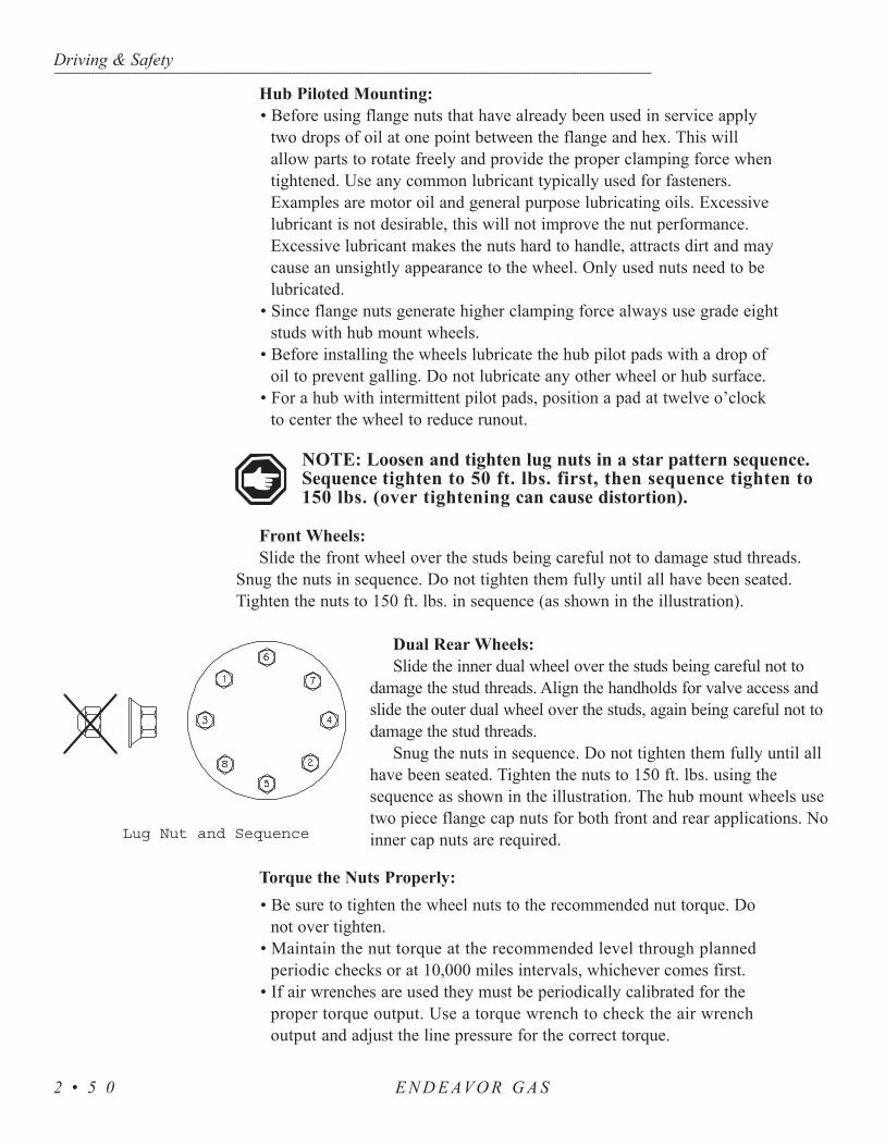
Hub Piloted Mounting:• Before using flange nuts that have already been used in service apply
two drops of oil at one point between the flange and hex. This willallow parts to rotate freely and provide the proper clamping force whentightened. Use any common lubricant typically used for fasteners.Examples are motor oil and general purpose lubricating oils. Excessivelubricant is not desirable, this will not improve the nut performance.Excessive lubricant makes the nuts hard to handle, attracts dirt and maycause an unsightly appearance to the wheel. Only used nuts need to belubricated.
• Since flange nuts generate higher clamping force always use grade eightstuds with hub mount wheels.
• Before installing the wheels lubricate the hub pilot pads with a drop ofoil to prevent galling. Do not lubricate any other wheel or hub surface.
• For a hub with intermittent pilot pads, position a pad at twelve o’clockto center the wheel to reduce runout.
NOTE: Loosen and tighten lug nuts in a star pattern sequence.Sequence tighten to 50 ft. lbs. first, then sequence tighten to150 lbs. (over tightening can cause distortion).
Front Wheels:Slide the front wheel over the studs being careful not to damage stud threads.
Snug the nuts in sequence. Do not tighten them fully until all have been seated.Tighten the nuts to 150 ft. lbs. in sequence (as shown in the illustration).
Dual Rear Wheels:Slide the inner dual wheel over the studs being careful not to
damage the stud threads. Align the handholds for valve access andslide the outer dual wheel over the studs, again being careful not todamage the stud threads.
Snug the nuts in sequence. Do not tighten them fully until allhave been seated. Tighten the nuts to 150 ft. lbs. using thesequence as shown in the illustration. The hub mount wheels usetwo piece flange cap nuts for both front and rear applications. Noinner cap nuts are required.
Torque the Nuts Properly:• Be sure to tighten the wheel nuts to the recommended nut torque. Do
not over tighten.• Maintain the nut torque at the recommended level through planned
periodic checks or at 10,000 miles intervals, whichever comes first.• If air wrenches are used they must be periodically calibrated for the
proper torque output. Use a torque wrench to check the air wrenchoutput and adjust the line pressure for the correct torque.
Driving & Safety----------------------------------------------------------------------------------------------------------------------------------------------------------------------------------------------------------------------------------------------------------------------------------------------------------------------------------
E N D E AVO R G A S2 • 5 0
Lug Nut and Sequence

Driving & Safety--------------------------------------------------------------------------------------------------------------------------------------------------------------------------------------------------------------------------------------------------------------------------------------------------------------------
E N D E AVO R G A S 2 • 5 1
Clean the wheel covers frequently with high pressure water from a hoseusing a mild detergent. Do not use harsh alkalis, alcohol or acidic cleansers. Asecondary hand washing with a soft cloth may be required to remove stubbornroad grime. To remove the wheel covers from the wheel for a thorough cleaninguse the special tool that was included with the motorhome. Each wheel coveris secured by four lug covers identified by indent or notch markings. When thewheel covers are removed tires and rims can be cleaned and inspected.
Remove dirt, corrosion or any foreign materials from the tire side of the rimusing a wire brush. Do not use a wire brush or other abrasive substances toremove dirt and corrosion from the wheel covers. To maintain the originalappearance of the wheel covers the following procedures are recommended:
1. After installing new wheels (prior to operating your motorhome) use a sponge, cloth or soft fiber brush to wash the exposed wheel surfaces with a mild detergent/warm water solution.
2. Rinse thoroughly with clean water.3. Wipe dry to avoid water spots.4. Use a high quality, non-abrasive polish to remove stubborn road tars,
insects or hard to remove deposits.5. To protect the appearance surface on wheels covers, wax the cleaned
surface with a high quality car wax.6. Clean the wheel covers frequently to maintain their appearance.
1. Mirrors 5. Windshield Wipers2. Headlights 6. Identification Lamps3. Clearance Lights4. Engine Access Door
Care & Maintenanceof Wheel Covers
VIEWS - FRONT & REAR
44
3
6
7
2
5
1 1
11
4
55
1
6
22
3 3
1. Clearance Lights 6. Rear Tow Hitch2. Camera 7. Identification Lamps3. Third Brake Light4. Tail Lights5. License Plate
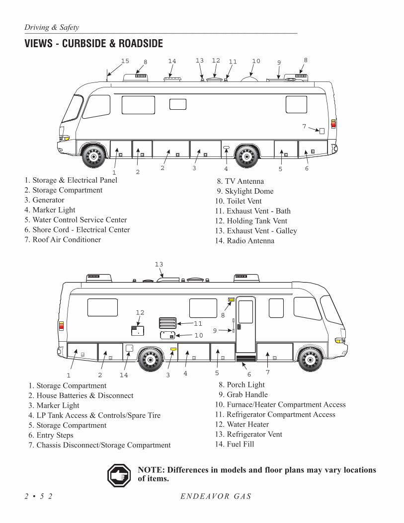
NOTE: Differences in models and floor plans may vary locationsof items.
Driving & Safety----------------------------------------------------------------------------------------------------------------------------------------------------------------------------------------------------------------------------------------------------------------------------------------------------------------------------------
E N D E AVO R G A S2 • 5 2
15
1 22 4 5 6
7
3
148 13 12 11 10 9 8
1. Storage & Electrical Panel2. Storage Compartment3. Generator 4. Marker Light5. Water Control Service Center6. Shore Cord - Electrical Center7. Roof Air Conditioner
8. TV Antenna9. Skylight Dome
10. Toilet Vent11. Exhaust Vent - Bath12. Holding Tank Vent13. Exhaust Vent - Galley14. Radio Antenna
1 2 14 3 4 5 6 7
910
11
13
12 8
1. Storage Compartment2. House Batteries & Disconnect3. Marker Light4. LP Tank Access & Controls/Spare Tire5. Storage Compartment6. Entry Steps7. Chassis Disconnect/Storage Compartment
8. Porch Light9. Grab Handle
10. Furnace/Heater Compartment Access11. Refrigerator Compartment Access12. Water Heater13. Refrigerator Vent14. Fuel Fill
VIEWS - CURBSIDE & ROADSIDE

Driving & Safety--------------------------------------------------------------------------------------------------------------------------------------------------------------------------------------------------------------------------------------------------------------------------------------------------------------------
E N D E AVO R G A S 2 • 5 3
MODEL 35SBD 35PBD 35WGS 36SGS 36PBD 36WGS
GVWR20,500
lbs.20,500
lbs.20,500
lbs.20,500
lbs.20,500
lbs.20,500
lbs.
GCWR25,500
lbs.25,500
lbs.25,500
lbs.25,500
lbs.25,500
lbs.25,500
lbs.
GAWR (Front)
7,000 lbs
7,000 lbs
7,000 lbs
7,000 lbs
7,000 lbs
7,000 lbs
GAWR (Rear)
13,500 lbs
13,500 lbs
13,500 lbs
13,500 lbs
13,500 lbs
13,500 lbs
Wheel Base
228" 228" 228" 228" 228"
Overall Length
35' 11" 35' 36' 36' 36'
Overall Height
11'9" 11'9" 11'9" 11'9" 11'9" 11'9"
Interior Height
6'6" 6'6" 6'6" 6'6" 6'6" 6'6"
Interior Width
94.5" 94.5" 94.5" 94.5" 94.5" 94.5"
Exterior Width
100" 100" 100" 100" 100" 100"
CHASSIS SPECIFICATIONS
SPECIFICATIONS - DIMENSIONS CHART

A ground fault circuit interrupter “GFCI” can be found in two different types ofapplications. One type is incorporated in a breaker used in 120 Volt AC breaker panels,the other is incorporated in an outlet. The GFCI, whether it is a breaker or an outlet,offer two types of protection. One type of protection is from over-current or shorts.It also provides protection for persons against hazardous ground fault currents whichcan result in injury or death. Ground fault currents are currents that flow from the“HOT” or power terminal through a person to the ground. For example, touching afaulty appliance while standing on or making contact with an electrical ground suchas a water fixture, bathtub or the earth. If the device has been properly installed itwill offer protection against the type of shock that can result from faulty insulation,wet wiring from inside an appliance, or any device or equipment plugged in orwired to that circuit. The “ground fault” portion of the outlet or breaker uses sensi-tive electronics inside the outlet or breaker to detect a ground fault problem. Theelectronics monitor the normal current of power, flowing to the “hot” or black wirethrough the load (eg. a light bulb or appliance) and coming back on the “neutral” orwhite wire. If just a small amount of the current comes back on the safety groundwire the electronics will “trip” the breaker or outlet, stopping the flow of electricity.The amount of current it takes to trip the device from a ground fault varies slightlyfrom the different outlet or breaker manufacturers (approximately 30 mils or less).Electrical shocks resulting from ground faults can be felt, but such a shock isconsiderably less than one without ground fault protection. People with heart conditionsor other conditions that make them susceptible to shocks can still be seriouslyinjured. A GFCI outlet or breaker will not protect against shock from a normal currentflow. For example, a shock from touching both metal prongs of an electrical cord orappliance while plugging it in.
WARNING: If a breaker or outlet trips continually DO NOTcontinue to reset breaker or outlet until the problem has been iden-tified and corrected.
NOTE: The ground fault outlet or breaker should be tested oncea month to insure it is working properly. Use the “TEST” buttonon the outlet or breaker. It should trip with an audible “click.”The breaker or outlet will not trip if no AC power is present tothe device. If power is present and the device will not “trip,”replace it before using that circuit.
NOTE: One mil is 1/1000 of one amp.
Driving & Safety----------------------------------------------------------------------------------------------------------------------------------------------------------------------------------------------------------------------------------------------------------------------------------------------------------------------------------
E N D E AVO R G A S2 • 5 4
GFCI BREAKERS &OUTLETS

Statistics show that most fire casualties are notcaused by direct flame, but by less visible smoke(products of combustion).
The smoke detector responds to both visible andinvisible products of combustion. The smoke detectorwill automatically return from alarm to normal statewhen the reason for activation, the presence of smoke,is completely removed.
Common causes of fires are smoking in bed, leavingchildren unattended and cleaning with flammable fluids.Please be safety conscious and avoid unnecessary risk.
WARNING: There is no way to insure against injury or lossof life in a fire; however, the smoke detector is intended tohelp reduce the risk of tragedy. Additional smoke detectorsmay help to reduce the risk. Proper use and care of thesmoke detector could save lives.
To test the electronics of the alarm press the test button on the cover of thesmoke alarm for a few seconds. The smoke alarm will sound by making acontinuous loud beep. To complete the test sequence release the button and thealarm should stop.
NOTE: Test the smoke alarm operation after the motorhomehas been in storage, before each trip and at least once a weekduring use.
Vacuum the slots in the cover and sides with a soft brush attachment everymonth. The smoke alarm should be cleaned every six months to help keep theunit working efficiently.
The battery should power the smoke alarm for at least one year undernormal use. When the battery reaches the end of its normal life a low batterywarning (intermittent beeping) will indicate the need for battery replacement.Some owners may find it practical to replace the battery during the timechanges in the spring and fall.
Driving & Safety--------------------------------------------------------------------------------------------------------------------------------------------------------------------------------------------------------------------------------------------------------------------------------------------------------------------
E N D E AVO R G A S 2 • 5 5
SMOKE DETECTOR
How to Test
Maintenance
SmokeSensingChamber

If the alarm does not sound when the test button is pushed, or with a smoke test,try the following:
• Inspect for obvious damage.• Check for the recommended battery type. • Check the battery for proper connection, or replace
the battery if needed.• Gently vacuum as recommended.
If these procedures do not correct the problem, do not attempt repairs. If thesmoke alarm is within the warranty period and the terms indicate the nature of theproblem, return the unit to the dealer. Smoke detectors beyond warranty cannot beeconomically repaired.
Abnormal air conditions may cause the highly sensitive smoke alarm to give afalse alarm. If no fire is apparent ventilate the room and/or blow fresh air into themotorhome until the alarm stops. Once cleared the smoke alarm will automaticallyreset. Dust can lead to excessive sensitivity. Vacuum as needed.
Provided for safety is a gas detector. This gas detector will detect both LP-Gasand Methane Gas. Liquefied Petroleum (LP) Gas is heavier than air, Methane Gas islighter than air. LP-Gas will settle to the lowest point, generally the floor of themotorhome. Methane Gas will rise. The gas detector is also sensitive to other fumessuch as hair spray, of which most contain butane as the propellant. Butane, likepropane is heavier than air and will settle to the floor level where it will be detected.When this occurs, press reset button to stop alert sound for 60 seconds.
The other combustibles which will be detected include alcohol, liquor, deodorants,colognes, perfumes, wine, adhesives, lacquer, kerosene, gasoline, glues, most of allcleaning agents and propellant of aerosol cans. Most are lighter than air in theirvapor state and will only be detected when the motorhome is closed up.
Upon first application of power the LED willflash yellow for three minutes while the detectoris stabilizing. At the end of the start cycle theLED will turn Green indicating full operation. Ifthe detector senses unsafe levels of gas it willimmediately sound an alarm.
The gas detector operates on 12 Volts, with acurrent draw less than 1/10th of one amp.
CAUTION: This detector will notalarm during the three minutewarm up cycle.
Driving & Safety----------------------------------------------------------------------------------------------------------------------------------------------------------------------------------------------------------------------------------------------------------------------------------------------------------------------------------
E N D E AVO R G A S2 • 5 6
Troubleshooting
LP-GAS DETECTOR
Operation

Depress the TEST switch any time during the warm up cycle or while innormal operation. The LED should flash red and the alarm should sound.Release the switch. This is the only way you should test the detector. The testfeature checks full operation of the detector.
WARNING: Test the operation of this detector after themotorhome has been in storage, before each trip and at leastonce per week during use.
The red LED will flash and the alarm will sound whenever a dangerouslevel of propane or methane gas is detected. The detector will continue toalarm until the gas clears or the Mute switch is pressed.
Procedures To Take During An Alarm:1. Turn off all gas appliances (i.e. stove, heaters, furnace). Extinguish all
flames and smoking material. Evacuate, leave doors and windows open.2. Turn off the propane tank valve. 3. Determine and repair the source of the leak. Seek professional help if
necessary.
CAUTION: Do Not re-enter until the problem is corrected.
Alarm Mute:Press the Test-Mute button when the detector is in alarm.1. The red LED will continue flash and the alarm will beep every 30
seconds until the gas level has dropped to a safe level. 2. The LED will flash green until the end of the Mute cycle.3. If dangerous gas levels return before the end of the mute cycle the alarm
will beep four times and return to phase 1. 4. After two minutes the detector will return to normal operation
(solid green) or resound the alarm if dangerous levels of gas remain in the area.
Fault Alarm:Should the microprocessor sense a fault in the gas detector a fault alarm
will sound twice every 15 seconds. The LED will alternately flash red togreen and the MUTE switch will not respond to any command. The gasdetector must be repaired or replaced.
1. Vacuum the dust off the detector cover weekly (more frequently in dusty locations) using the soft brush attachment of the vacuum.
2. Do not spray cleaning agents or waxes directly onto the front panel. This action may damage the sensor, cause an alarm or cause a detector malfunction.
Driving & Safety--------------------------------------------------------------------------------------------------------------------------------------------------------------------------------------------------------------------------------------------------------------------------------------------------------------------
E N D E AVO R G A S 2 • 5 7
Alarm
Testing
Care

The motorhome is equipped with a carbon monoxidedetector. Carbon monoxide (CO) is a colorless, odorless andtasteless gas. Even low levels of CO have been known tocause brain and other vital organ damage in unborn infants,with no effect on the mother. In cases of mild exposure thesymptoms may include: a slight headache, nausea, vomitingand fatigue. Symptoms for medium exposure may include asevere throbbing headache, drowsiness, confusion and fastheart rate. Extreme exposure can result in unconsciousness,convulsions, cardio-respiratory failure and death. Youngchildren and household pets may be the first effected. TheCO detector is designed to detect the toxic CO fumes thatresult from vehicle exhaust and incomplete combustionsources like a furnace, gas stove or water heater.Consequently, it is uncommon for household smoke fromcigarettes or normal cooking to cause the alarm to sound.
NOTE: Activation of this device indicates the presence of carbonmonoxide (CO) which can be fatal. A concentration of above 100PPM will cause a warning condition. Individuals with medicalproblems may consider using detection devices with lower carbonmonoxide alarming capabilities. Prolonged exposure to the hornat a close distance may be harmful to the hearing.
The detector is equipped with a self-cleaning CO sensor and requires a tenminute initial warm-up period to clean the sensor element and achieve stabilization.The green power light should be lit when the power is on. If the light is not lit, turnoff the power and check all wire connections. If the power is on and the connectionsare correct but the indicator still does not light, the detector should be returned forservice. Do not attempt to fix the detector yourself. The indicator light displays aspecific color to monitor the conditions as follows:
• Green - Indicates an “ON” or normal condition. The CO detector has power and is sensing air for the presence of CO gas. The alarm horn will not sound.
• Yellow - Indicates a “trouble” or malfunction condition. The alarm horn will sound and cannot be reset by the TEST/RESET button. The CO detector is not working properly and must be immediately replaced or repaired.
• Red - Indicates an “alarm condition.” The detector has sensed the presence of a hazardous level of carbon monoxide. The alarm horn will sound continuously until reset by the RESET switch.
Driving & Safety----------------------------------------------------------------------------------------------------------------------------------------------------------------------------------------------------------------------------------------------------------------------------------------------------------------------------------
E N D E AVO R G A S2 • 5 8
CARBON MONOXIDE DETECTOR
OperatingInstructions

When the alarm sounds you should have the detector and the motorhomechecked by an authorized service technician as soon as possible. Never discon-nect a CO detector to silence an annoying alarm. Evacuate the motorhomeimmediately when the red light is lit and the alarm sounds. Do a head count tocheck that all persons are accounted for. Call the nearest fire department andask them to determine the source of the carbon monoxide. Do not re-enter themotorhome until it has been aired out and the problem corrected.
Test the carbon monoxide detector operation after the motorhome has beenin storage, before each trip and at least once a week during use. You can testthe alarm by holding the test button in until the alarm sounds. The alarm willstop beeping in about 30 seconds.
Use a vacuum cleaner to remove dust or any other buildup on the detector.Do not wash. Wipe the detector with a damp cloth and dry it with a towel. Donot open the detector for cleaning. Do not paint the detector. It is recommendthat the carbon monoxide detector should be replaced every 10 years.
The fire extinguisher in the motorhome is located near the mainentrance door. Please read the operating instructions that are printedon the fire extinguisher. If there is any doubt on how to operate thefire extinguisher, you and the family should practice using it. Besure to replace or recharge the extinguisher immediately after use.
Inspect the fire extinguisher at least once a month. Do so morefrequently if the extinguisher is exposed to weather or possibletampering. Do not test the extinguisher by partially discharging, thiswill cause a loss of pressure.
Use the PASS word!
Pull the pin to unlock the extinguisher.Aim at the base (bottom) of the fire and stand 6-10 feet away.Squeeze the lever to discharge the agent.Sweep the spray from left to right until totally extinguished.
Driving & Safety--------------------------------------------------------------------------------------------------------------------------------------------------------------------------------------------------------------------------------------------------------------------------------------------------------------------
E N D E AVO R G A S 2 • 5 9
Testing
Cleaning
Alarm
FIRE EXTINGUISHER

An egress window is designated for use as an exit inthe case of an emergency. Inside the motorhome theegress window is easily identified by the red locking handle.It is also marked as an “EXIT.” On the outside of themotorhome the egress window is identified by hingesvisible along the top of the window.
The glass slider in the egress window operates similarto other windows. To open the egress window, lift the redhandle and push outward on the window. Pull the windowclosed and lower the handles to lock the egress window.
The egress window should be opened twice a year toensure proper operation. The rubber seal tends to stick tothe egress window.
Driving & Safety----------------------------------------------------------------------------------------------------------------------------------------------------------------------------------------------------------------------------------------------------------------------------------------------------------------------------------
E N D E AVO R G A S2 • 6 0
EGRESS EXIT WINDOW

Driving & Safety--------------------------------------------------------------------------------------------------------------------------------------------------------------------------------------------------------------------------------------------------------------------------------------------------------------------
2 • 6 1E N D E AVO R G A S
NOTES

Driving & Safety----------------------------------------------------------------------------------------------------------------------------------------------------------------------------------------------------------------------------------------------------------------------------------------------------------------------------------
2 • 6 2 E N D E AVO R G A S

33EXTERIOR CARE • 65
Corrosion • 65 Washing • 65
Drying • 66Waxing • 66
Bright Metal • 67Maintenance - Exterior • 67
Seal Inspections • 68Sealant Types • 68
INTERIOR CARE • 69Fabrics • 69
Vinyl • 74Naugahyde • 76
Floor - Carpet Cleaning • 77Floor - Vinyl • 79
Floor - Laminate • 81Floor - Tile • 81
Shower - Cleaning • 82Ceiling - Ozite • 82
Wall Coverings • 82Countertops - Solid Surface • 83
Countertops - Granicoat • 84Countertops - Laminate • 85
Windows • 86Mini-Blinds • 87
Day/Night Shades • 87STORAGE - Short Term • 87
Storage - Long Term • 87Storage - Removal • 90
SECTION 3CARE & MAINTENANCE
GAS


The most common cause of corrosion to the motorhome is the accumulationof road salts, grime and dirt. These elements, combined with moisture, maypossibly cause early component failure. Salt air and fog from coastal trips cangreatly accelerate the corrosion process. Corrosive materials collected fromroadways accumulate on the undercarriage, around wheel openings and on theradiator charge air cooler package. These areas need to be cleaned periodicallyto help prevent component failure due to corrosion. If the motorhome is drivenin areas where road salts are used it should be washed at least once a week.Otherwise, it is recommended to hose off the undercarriage area at least once amonth to help minimize the corrosion process. High pressure washers or steamcleaners are the most affective way of cleaning off the underside and insidewheel openings. Avoid directly spraying the painted surface with a highpressured washer. Remove road debris and mud that has accumulated.Material left behind can intensify the corrosion problem.
CAUTION: Exercise caution when cleaning the radiatorcharge air cooler package. Damage to the fins can result when using a high pressure washer or steam cleaner. Nozzledischarge pressure can exceed 1,800 psi. Avoid using high pressure steam cleaners on the exterior paint surfaces.Remove all spattered washing debris from the exterior paintsurfaces as soon as possible.
The life of the exterior paint finish can be extended if properly cared for.Periodic cleaning will help preserve the paint finish. The motorhome is paintedwith a “base coat, clear coat system.” The clear coat is a polyurethane basedmaterial which brings out the shine or luster to the base coat paint. Care shouldbe used when washing the motorhome. Use only mild detergents or preferredspecifically designed automotive detergents. Avoid using abrasive cleansers orlaundry detergents as they will scratch the clear coat and leave a soap film. Theuse of specially designed automotive washing utensils such as soft bristlebrushes are acceptable, as long as they do not trap abrasive material andscratch the surface while being used. Before washing the motorhome removemost of the accumulated dirt and “road wash” behind wheel openings, belowthe windshield and on the rear of the motorhome. If the build up is excessiverun water over a soft brush while gently scrubbing the surface in one direction.This will help float away the “build-up” from the clear coat. Avoid back andforth or circular motions as this may act like sandpaper, scratching the clearcoat and leaving a haze or “swirl marks.” After removing the heavy build-upuse the mixed detergent solution to wash the motorhome. Start washing at thetop of the motorhome working towards the bottom. If possible, wash themotorhome in a shaded area when the exterior is not hot to the touch. If necessary,turn the motorhome around to keep the area being washed in the shade. Try notto allow the detergent to dry onto the clear coat surface. Use plenty of waterwhen rinsing the surface to remove any detergent residue.
Care & Maintenance--------------------------------------------------------------------------------------------------------------------------------------------------------------------------------------------------------------------------------------------------------------------------------------------------------------------
E N D E AVO R G A S 3 • 6 5
EXTERIOR CARECorrosion
Washing

Drying chamois cloths come in natural and synthetic materials. Either type isacceptable as long as the surface is clean. Soak the chamois in clean water until allchamois material has absorbed water. Wring excess water from chamois. Start at thetop and work towards the bottom. Use a downward “S” pattern to remove waterfrom the surface and wring out the chamois as needed. Using a chamois cloth toremove the rinse water is not necessary, but the effort can be worthwhile.
To wax or not to wax? This is a good question. There are many schools ofthought on this issue. The two most common thoughts are:
• The clear coat needs to “breathe.” A layer of wax will seal the clear coat not allowing it to breathe, possibly leading to failure of the clear coat.
• If the surface is not waxed, what is protecting the surface from the environment (road salts, acid rain, road tar, ultraviolet light)?
It is recommended to wax the motorhome twice a year: spring and fall. Manytypes of protective barriers are available today that may be applied to the clear coat:glazes, waxes, polishes, rubbing compounds or combinations of these products.
NOTE: When selecting a product for use follow the product manufacturer’s recommended application instructions.
Types of Products:Glazes: Glazes are generally used to fill very fine scratches in the clear coat,
being applied either by hand or by using a polisher with a special pad.
Waxes: Waxes come in many types of chemical make-ups. The popularCarnauba wax is a natural occurring wax from the leaves or fronds of the Carnaubapalm tree. Mineral waxes have a paraffin base. There are also other topical applicationproducts which contain silicone.
Polishes: Polishes usually contain a combination of wax based substances withan abrasive, getting the two for one idea. These products can be too abrasive forclear coats and are not recommended for use.
Rubbing Compounds: These types of products are generally applied by using abuffer. The use of rubbing compounds should be left to professionals as undesiredresults can occur quickly. These types of products are generally used to correct orflatten a surface by removing high spots or small amounts of material.
When selecting a product the container should be marked “safe for clear coats”or “clear coat safe.” Carefully follow all manufacturer’s application instructionswhen using a product. Upon first use of a product try it on a “small test spot” in an
Care & Maintenance----------------------------------------------------------------------------------------------------------------------------------------------------------------------------------------------------------------------------------------------------------------------------------------------------------------------------------
E N D E AVO R G A S3 • 6 6
Drying
Waxing

inconspicuous area in case an undesired reaction occurs. Observe the test areafrom different angles checking for hazing or swirl marks. If an abnormal reaction to the finish results, discontinue product use and consult the product’smanufacturer. If the product is a paste do not allow dried paste to be baked onby the sun. Remove paste shortly after drying. Clean, dry, 100% cotton clothsor cotton baby diapers are best suited for the removal of dried paste. Turn thecloth often. Use a separate clean cloth to buff. The surface should feel “slick”when rubbing the cloth lightly over it. Avoid repeated wax applications whichcan cause wax to build up. Some very fine scratches or swirl marks may beremoved by application of a glaze. These types of glazes fill the scratches or swirlmarks.
The motorhome has a large surface area. Washing and waxing may not becompleted in one afternoon. Select sections to wax until the motorhome iscomplete. If the washing and waxing the motorhome seems overwhelminghave an automotive detailer perform the task.
All chrome, stainless steel and aluminum should be washed and cleaned eachtime the motorhome is washed. Use only automotive approved non-abrasivecleaners and polishes on exterior bright work. Do not use rubbing compounds.
NOTE: When using chemicals to remove road tars, use only automotive type products that are recommended foruse on painted surfaces and fiberglass. Observe the warning recommendations and directions printed on the container ofany agent being used.
The motorhome is subjected to a great deal of outside conditions. While thecoach is parked it is exposed to extreme temperatures, humidity, ultravioletrays, acid rain and other organic environmental conditions. While the coach isin operation it is subjected to twisting and flexing caused by entering andexiting driveways, bouncing through potholes and traveling over windingroads.
Periodic inspections of the fiberglass exterior may reveal minute cracks inthe surface commonly called “spider cracks” or “hairline cracks,” which arecaused by the flexing of the fiberglass exterior. These are quite normal. If acrack represents a threat to the integrity of the fiberglass it will open up and theweave of the cloth would be visible. If the exterior has been damaged, preventmoisture penetration, especially in freezing climates. Cover the area as quicklyas possible. Use plastic sheeting and tape, if necessary, so that moisture willnot get into the motorhome and damage the interior.
Care & Maintenance--------------------------------------------------------------------------------------------------------------------------------------------------------------------------------------------------------------------------------------------------------------------------------------------------------------------
E N D E AVO R G A S 3 • 6 7
Bright Metal
Maintenance- Exterior

Periodic resealing of the joints and seams is necessary to prevent the entrance ofmoisture into the motorhome. Enough emphasis cannot be placed on this issue.Extreme damage from a water leak can occur rapidly. Never leave the vehicleunattended with the slide room extended. If the vehicle is to be stored outsidethroughout the winter months a full interior inspection for water leaks should bemade bi-monthly. Extensive sealing has been done at the factory; however, the twist-ing and flexing that normally occurs while traveling may have compromised a sealor seam. All joints and seams should be inspected at least twice a year and recalkedas necessary. Special attention should be directed toward the roof air conditioningseals, ceiling and plumbing vents, skylights, roof mounted antennas, windows, doormolding, clearance lights and the beltline molding. Specific sealant products shouldbe used in the areas for which they were designed. These items can be obtainedfrom recreational vehicle parts suppliers. Listed below are some of the more commonsealants and the areas in which they are used. Approved sealants are available atservice centers and authorized dealers.
WARNING: Some products may contain hazardous materialswhich require special handling. Read labels carefully. Followall product manufacturer’s safety requirements.
Acryl-R:This product is used on all roof openings such as vents, skylights, roof mounted antennas and ladder roof mounts, with exception to the roof air conditioners. The sealant should be applied only where the equipment base meets the roof. Clean old sealant that is lifting before applying the new sealant. Make sure the roof is dry and free of dirt. Acryl-R is usually available in a caulking tube. Using masking tape, mask around edges of the area to avoid mishaps as the product spreads out after application.
The roof air conditioners have closed cell foam base gaskets. No sealants are required. The roof air conditioners should be checked for tightness by the four mounting bolts located in each corner of the air conditioner roof opening. Torque specification is 40-50 in./lbs. The base gasket should be compressed to approximately ½ inch.
Clear Silicone Sealant:Primarily this product is used on the sidewalls where a hole has been made and an item installed. This includes Windows, Doors, Handles, Beltline Molding, Latches and around bases of items surface mounted such as clearance lights. Old peeling sealant should be removed. Avoid using metal utensils as these will scratch the painted surface. Use nylon sticks or equivalent. Avoid using lacquer thinners or ketone based solvents as these chemicals can damage the painted surfaces. Be sure the surface is clean and dry before application. Cut tube at an angle with smallest usable opening. Avoid a heavy bead as a little goes a long way.
Care & Maintenance----------------------------------------------------------------------------------------------------------------------------------------------------------------------------------------------------------------------------------------------------------------------------------------------------------------------------------
E N D E AVO R G A S3 • 6 8
Seal Inspections
Sealant Types

Wear a disposable latex glove and use a dry finger at a 45° angle to smooth out the silicon beads. Keep rags or paper towels handy for clean up. Use care when applying silicone. Plan ahead before starting a bead, looking for obstacles that may impede application.
Black Urethane:This product is used for sealing the windshields. It was not designed to fill holes or other imperfections. Black urethane comes in a tube and it applies much in the same way as silicone does. Clean up involves using solvents such as paint thinner. Gloves are required as this material is hazardous.
Acrylic Sealants (geocel 2300):This product is used where items are sealed under a painted surface such as the metal corners of the slide-out room. The material is specially formulated to allow paint adhesion.
Spray Foam:This product is used to seal where a hole has been made for items such as water lines or wires are coming through a floor opening.
Black Seam Tape (Use may vary with models):This is a sticky tape which comes on a roll. Black seam tape is used on the front and rear roof seams, as well as on the roof to the sidewall corners of the slide out room. Cut away old lifting tape. Surface should be clean and dry before a new application is made. This may be done in sections as needed.
The fabrics have been manufactured with the same quality you wouldexpect to find in a furniture store. If the fabric is abused it can be damaged.Special care needs to be taken when your motorhome is exposed to a veryhumid climate for an extended period of time. Cover all upholstery and makesure window coverings are down to protect from sun damage.
Protect the fabric from any unnecessary exposure to moisture. The sofa, pillows, dinette cushions, living area chair, driver/passenger seating and window treatments have been treated with Scotch Guard to prevent overallwater spots and soiling. Frequently used items will wear accordingly and mayrequire more attention than those items not regularly used.
Care & Maintenance--------------------------------------------------------------------------------------------------------------------------------------------------------------------------------------------------------------------------------------------------------------------------------------------------------------------
E N D E AVO R G A S 3 • 6 9
INTERIOR CARE - Fabrics
Use the following guidelines for cleaning your upholstery fabrics:
• Water-based cleaners are not recommended.• If a spill does occur, blot the soiled area. Do not rub it.• Some solvents are not recommended since they may have an adverse
reaction on specific backings of your upholstery fabric.• To prevent overall soiling, frequent vacuuming or light brushing are
recommended to remove dust and grime.• Clean spots using a mild water-free solvent or dry cleaning product.• Clean only in a well ventilated area and avoid any product containing
carbon tetrachloride or other toxic materials.• Use a professional furniture cleaning service for an overall cleaning.
Fabric Cleaning Codes:The codes listed below refer to cleaning instructions recommended by the fabric
manufacturer for specific fabrics. The “Fabric Specification Charts” (located on thefollowing pages) list specific fabric codes under “Cleaning Code.”
“W” - Clean this fabric with the foam only of a water-based cleaning agent to remove the overall soil. Many household cleaning solvents are harmful to the color and life of a fabric. Cleaning only by a professional furniture cleaning service is recommended. To prevent overall soil, frequent vacuuming or light brushing to remove dust and grime is recommended.
“S” - Clean this fabric with pure solvents (petroleum distillate-based products such as Energine, Carbona, Renuzit, or similar products may be used) in a well ventilated room. Cleaning only by a professional furniture cleaning service is recommended.
CAUTION: Use of water-based or detergent-based solvent clean-ers may cause excessive shrinking. Water stains may become per-manent and unable to be removed with solvent cleaning agents.Avoid products containing Carbon Tetrachloride as it is highlytoxic. To help prevent overall soiling, frequent vacuuming or lightbrushing to remove dust and grime is recommended.
“S/W” - Clean this fabric with the foam only of a water-based cleaning agent or with a pure solvent in a well ventilated room (petroleum distillate-based products such as Energine, Carbona, Renuzit, or similar products may be used). Cleaning only by a professional furniture cleaning service is recommended. To help prevent overall soiling, frequent vacuuming or light brushing to remove dust and grime is suggested.
Care & Maintenance----------------------------------------------------------------------------------------------------------------------------------------------------------------------------------------------------------------------------------------------------------------------------------------------------------------------------------
E N D E AVO R G A S3 • 7 0

“P” - The article is resistant against perchlorethene, cleaning benzine (spirit), white spirit, R-11 and R-13.
“Dry Clean Only” - Cleaning only by a professional dry cleaner or furniture cleaning service is recommended for this fabric.
*Machine Washing for 100% Polyester:“Wash Cycle” - Use synthetic setting and high water level with mild agitation. A mild soap or detergent in water not to exceed 160º F. No bleach or fabric softener.
“Drying” - Use low temperatures, a synthetic setting of 85º F to 90º F maximum should be used. Do not exceed three to five minutes time on the synthetic cycle. If washed at 160º F, the maximum temperature which can be used to dry is 140º F. Hang or fold immediately after drying.
“Finishing” - If necessary, press as following:• Iron on low setting (275° F) with damp cloth or steam iron using a dry
press cloth.• Grid Head press for short intervals with minimum steam. Do not lock
the head.• Flat bed press dampened drapery using cloth covering.• Avoid prolonged contact with heat.
Care & Maintenance--------------------------------------------------------------------------------------------------------------------------------------------------------------------------------------------------------------------------------------------------------------------------------------------------------------------
E N D E AVO R G A S 3 • 7 1

Care & Maintenance----------------------------------------------------------------------------------------------------------------------------------------------------------------------------------------------------------------------------------------------------------------------------------------------------------------------------------
E N D E AVO R G A S3 • 7 2
Fabric Specification Chart:
Fabric Where Used
Andante Prism Sofa, Din Cushion, LR Pillow, LR LamOrigin 1553 MO12353-009 Chair, FSD, LR Pillow, LR LamReiss Denim Bedspread, BR Pillow, Headboard, BR LamDiamon AV Kir Bedspread, BR Pillow, BR LamRVAA Pearl LeatherBrunswick Pearl VinylPearl 009 Natural Windshield
Piram Martini Sofa, Din Cushion, LR Pillow, LR LamMetropolis Amber Chair, FSD, LR Pillow, LR LamHarlow - SH Twilight Bedspread, BR Pillow, Headboard, BR LamShantung - SH Truffle Bedspread, BR Pillow, BR LamRVAA New Oyster LeatherBrunswick New Oyster VinylPearl 009 Natural Windshield
P4174 Opal Sofa, Din Cushion, LR Pillow, LR LamNorwich Wedgewood Chair, FSD, LR Pillow, LR LamAshbrook Multi Bedspread, BR Pillow, Headboard, BR LamJester - TR Sapphire Bedspread, BR Pillow, BR LamRVAA Pearl LeatherBrunswick Pearl VinylPearl 009 Natural Windshield
Cayman Jungle Sofa, Din Cushion, LR Pillow, LR LamDazzle 010 Chair, FSD, LR Pillow, LR LamMonarch Moss Bedspread, BR Pillow, Headboard, BR LamDiamond AV Pine Bedspread, BR Pillow, BR LamRVAA New Oyster LeatherBrunswick New Oyster VinylPearl 009 Natural Windshield
Rosewood
Toffee
Nordic Blue
Silver Pine
LR = Living RoomBR = Bedroom
FSD = Free Standing Dinette
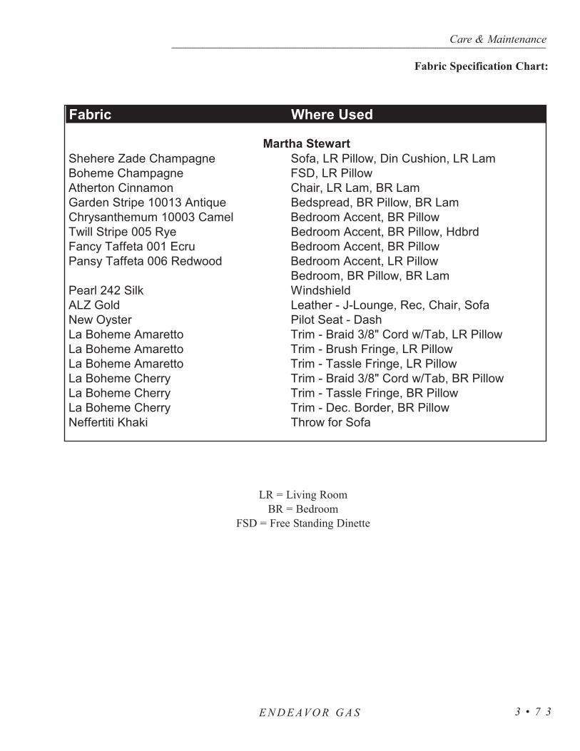
Care & Maintenance--------------------------------------------------------------------------------------------------------------------------------------------------------------------------------------------------------------------------------------------------------------------------------------------------------------------
E N D E AVO R G A S 3 • 7 3
Fabric Where Used
Shehere Zade Champagne Sofa, LR Pillow, Din Cushion, LR LamBoheme Champagne FSD, LR PillowAtherton Cinnamon Chair, LR Lam, BR LamGarden Stripe 10013 Antique Bedspread, BR Pillow, BR LamChrysanthemum 10003 Camel Bedroom Accent, BR PillowTwill Stripe 005 Rye Bedroom Accent, BR Pillow, HdbrdFancy Taffeta 001 Ecru Bedroom Accent, BR PillowPansy Taffeta 006 Redwood Bedroom Accent, LR Pillow
Bedroom, BR Pillow, BR LamPearl 242 Silk WindshieldALZ Gold Leather - J-Lounge, Rec, Chair, SofaNew Oyster Pilot Seat - DashLa Boheme Amaretto Trim - Braid 3/8" Cord w/Tab, LR PillowLa Boheme Amaretto Trim - Brush Fringe, LR PillowLa Boheme Amaretto Trim - Tassle Fringe, LR PillowLa Boheme Cherry Trim - Braid 3/8" Cord w/Tab, BR PillowLa Boheme Cherry Trim - Tassle Fringe, BR PillowLa Boheme Cherry Trim - Dec. Border, BR PillowNeffertiti Khaki Throw for Sofa
Martha Stewart
LR = Living RoomBR = Bedroom
FSD = Free Standing Dinette
Fabric Specification Chart:

Several areas of the motorhome can be covered in vinyl. These areasinclude the dash, items of furniture and the ceiling. The care and cleaning ofthese areas are outlined in the Morbern Vinyl section below.
Morbern Vinyl:Vinyl requires periodic cleaning to maintain its neat appearance and to pre-
vent the buildup of dirt and contaminants that may permanently stain and/orreduce the life of the vinyl if they are not removed. The frequency of cleaningdepends upon the amount of use and the environmental conditions in which thevinyl is subjected. The procedures used for cleaning are dependent upon theend-use circumstances.
Normal Cleaning:Most common stains can be cleaned using warm soapy water and clear
water rinses. Moderate scrubbing with a medium bristle brush will help toloosen soil from the depressions of embossed surfaces. For stubborn stains,use the following commercially available mild detergents in accordance withthe manufacturer’s instructions: Mr. Clean or Fantastik. Full strength rubbingalcohol or mineral spirits may be tried cautiously as a last resort on very stub-born stains if the above suggestions do not work. Indiscriminate use of any sol-vent, or solvent containing cleaner, can severely damage or discolor the vinyl.Stains may become permanent if they are not removed immediately. The proce-dure for removal of the more severe staining agents are outlined below.
NOTE: Detergents should never be used on a regular or repeatedbasis for normal cleaning.
CAUTION: Powdered cleaners containing abrasives, steel wool andindustrial strength cleaners are not recommended for Morbernvinyl.
Bird Excreta & Vomit Stains:Sponge the area with soapy water containing a diluted bleach until the stain is removed. Rinse thoroughly with clean water.
Urine Stains:Sponge them with soapy water containing a small amount of household ammonia. Rinse thoroughly with clean water.
Surface Mildew:Wash with diluted bleach and use a soft brush for stubborn growth. Rinse repeatedly with clear, cold water.
Care & Maintenance--------------------------------------------------------------------------------------------------------------------------------------------------------------------------------------------------------------------------------------------------------------------------------------------------------------------
E N D E AVO R G A S3 • 7 4
Vinyl

CAUTION: Any lacquer solvent will cause immediate irrepara-ble damage to the vinyl. Wax should never be used on any vinylupholstery as it will cause premature embrittlement and crack-ing. Dilute chlorine bleach before using. Never use full strengthbleach. If flammable solvents such as alcohol, turpentine or var-sol are used for cleaning, use only small quantities while in awell-ventilated area. Exercise proper caution by notifying anypersons in the area. Keep away from any ignition source.Always wear protective gloves.
Ballpoint Ink:Permanent Marker Ink spots will stain the vinyl permanently. Wipe the stain immediately with rubbing alcohol in a well ventilated area to remove much of the stain.
Oil-Base Paint:Use turpentine in a well ventilated area to remove any fresh paint. Dried paint must be moistened using a semi-solid, gel-type stripper. The softened paint can be gently scraped away. Rinse with soap and water.
NOTE: Paint strippers will remove the print pattern and damage the vinyl if it comes in direct contact.
Latex Paint:Fresh paint can be wiped off with a damp cloth. Hot soapy water will normally remove dried latex.
Tar or Asphalt:Remove immediately as prolonged contact will result in a permanent stain. Use a cloth lightly dampened with mineral spirits and rub the stain gently, working from the outer edge of the stain toward the center to prevent spreading. Rinse with soap and water.
Crayon, Mustard or Ketchup:Sponge with mild soap and water. For stubborn stains that may have set use a cloth soaked in diluted mild detergent with gentle rubbing. Any remaining stain should be washed with diluted bleach. Rinse repeatedly with cold water.
Chewing Gum:Scrape off as much gum as possible using a dull knife. Rub the gum with an ice cube to harden it and make it easier to remove. In a well ventilated area use a cloth saturated with mineral spirits and gently rub the remaining gum. Rinse thoroughly with clean water.
Care & Maintenance----------------------------------------------------------------------------------------------------------------------------------------------------------------------------------------------------------------------------------------------------------------------------------------------------------------------------------
E N D E AVO R G A S 3 • 7 5

Care & Maintenance--------------------------------------------------------------------------------------------------------------------------------------------------------------------------------------------------------------------------------------------------------------------------------------------------------------------
E N D E AVO R G A S3 • 7 6
Lipstick, Grease, Oil, Make-Up or Shoe Polish:Apply a small amount of mineral spirits with a cloth. Rub gently. Be careful not to spread the stain by smearing it beyond its original source. Remove shoe polish immediately as it contains a dye which causes permanent staining. Rinse thoroughly with clean water.
Candy, Ice Cream, Coffee, Tea, Fruit Stains, Liquor, Wine, Tanning Lotion or Soft Drinks:Use lukewarm water and sponge repeatedly. Any loose material should be gently scraped with a dull knife. Any soiled area that remains after drying should be gently rubbed with a cloth, dampened with a mild detergent solution. Rinse thoroughly with clean water.
Blood or Plant Residue:Use a clean cloth soaked in cold water and gently rub the stain. If stubborn spots remain use household ammonia and rinse repeatedly with a clean, wet cloth. Do not use hot water or soap suds as this will set the stain.
NOTE: Vinyl requires periodic cleaning to maintain its appearanceand to prevent the buildup of dirt and contaminants that may per-manently stain or reduce the life of the vinyl if left untreated. Thefrequency of cleaning and procedures used depend upon the amountof use and the environmental conditions in which the vinyl is sub-jected to. Vinyl tears or holes can be temporarily covered withclear “office” tape to prevent further damage. Repairs should bemade by a professional upholstery shop. Commercial repair prod-ucts may contain lacquers and cause the vinyl to become brittle andmore difficult to repair.
Naugahyde Leather is a vinyl coated fabric. The following care and cleaningmethods should be used to ensure the long lasting beauty of the fabric. For bestresults staining should be removed immediately. The longer a stain is allowedto set, the more difficult it becomes to remove it. Always use a clean, soft,damp cloth when cleaning the fabric.
Light soiling:• A solution of 10% liquid dish soap and warm water applied with the soft
damp cloth will remove most soiling.• Use a solution of liquid cleanser and warm water applied with a soft bristle
brush, if needed. Wipe away the residue with the soft cloth.
Naugahyde

Difficult stains:• Mix a solution of 1 part bleach to 4 parts water.• Dampen the soft cloth and rub gently.• Rinse with a water dampened cloth to remove the residue.• It may be necessary to allow the solution to puddle on the affected area for
30 minutes. Rinse using a water dampened cloth to remove the residue.
CAUTION: This method should be attempted on an inconspicuousspot prior to using on the stained area. Never use harsh solvents orcleanser intended for industrial use.
Stains such as lipstick, crayon, felt tip pen, ball point pen, mustard and certain dyedsuntan lotions must be cleaned immediately. The longer these and other harsh or per-manent stains are exposed to the fabric the more difficult they will be to clean.Other cleaning methods and cleaning agents may be attempted in an inconspicuousarea to determine possible damage to the fabric.
Spot Removal Procedures• Act quickly when anything is dropped or spilled. Remove spots before
they dry.• Blot liquids with a clean, white absorbent cloth or paper towel.• For semi-solids, scoop up with a rounded spoon.• For solids, break up and vacuum out as much as possible.• Pretest the spot removal agent in an inconspicuous area to make certain it
will not damage the carpet or its dyes.• Apply a small amount of the cleaning solution recommended for the
particular spot. Do not scrub. Work from the edges of the spot to the center. Blot thoroughly. Repeat until spot is removed.
• Follow steps on the Carpet Spot Removal Guide.• After each application absorb as much as possible before proceeding to
the next step.• Absorb remaining moisture with layers of white paper towels, weighted
down with a non-staining glass or ceramic object.• When completely dry, vacuum or brush the pile to restore texture.• If the spot is not completely removed contact a professional
carpet cleaner.
Care & Maintenance----------------------------------------------------------------------------------------------------------------------------------------------------------------------------------------------------------------------------------------------------------------------------------------------------------------------------------
E N D E AVO R G A S 3 • 7 7
Floors- Carpet Cleaning

Care & Maintenance--------------------------------------------------------------------------------------------------------------------------------------------------------------------------------------------------------------------------------------------------------------------------------------------------------------------
E N D E AVO R G A S3 • 7 8
Cleaning Solutions:(A) Dry Cleaning Fluid: Nonflammable spot
removal liquid, available in grocery and hardware stores.
(B) Nail Polish Remover: Any acetate, which often has a banana fragrance. Do not use if it contains acetone.
(C) Detergent Solution: Mix two cups of cold water and 1/8 teaspoon mild liquid detergent(no lanolin, non-bleach).
(D) Warm Water: Lukewarm tap water.
(E) Vinegar Solution: One cup white vinegar to one cup water.
(F) Ammonia Solution: One tablespoon household ammonia to one cup water.
(G) Spot Removal Kit: Available from retail carpet stores or professional cleaners.
(H) Call Professional: Additional suggestions, special cleaning chemicals or the ability topatch the area might be available.
(I) Permanent Change: Due to the nature of the stain there may be color loss. The carpet has been permanently dyed or the carpet yarns havebeen permanently damaged.
NOTE: *While the recommended cleaningagents have proven to be effective, somestains may become permanent.
A B C D E F G H I
Use the solution specified in order from 1-6 until stain is removed.
SPOTSAcid 2 1 3 *Acne Medication 1 2 5 4 3 6 *Alcoholic Beverage 1 4 3 2 *Ammonia 2 1 *Bleach 1 2 3 *Blood 1 3 2 4Candle Wax 1 2Cement & Glue 2 1 3 5 4 6 *Chalk 1 2Charcoal 1 2Chewing Gum 1Coffee 1 3 2 4 5 *Cosmetics 2 1 3 6 5 4 7 *Crayon 1 2 3Drain/Toilet Cleaner 2 1 3 4 *Dye 1 2 4 3 5 6 *Food 1 4 3 2 5 6 *Fungicides/Insecticides/Pesticides 1 2 5 4 3 6 *Furniture Polish (Water Based) 1 4 3 2 5 6 *Furniture Polish (Solvent Based) 2 1 3 6 5 4 7 8 *Furniture Stain 2 1 3 6 5 4 7 8 *Graphite 1 2Grease 1 2 3 4 5 *Ink 2 1 3 6 5 4 7 8 *Iodine 1 2 5 4 3 6 7 *Lipstick 2 1 3 6 5 4 7 8 *Medicine 2 1 3 6 5 4 7 8 *Merthiolate 1 4 3 2 5 6 *Nail Polish 2 1 3 4 5 *Oil 1 2 4 3 5 *Paint 2 1 3 4 5 *Plant Food 1 4 3 2 5 6 *Rust 2 3 1 4 5 *Shoe Polish 2 1 3 5 4 6 7 *Soft Drinks 1 4 3 2 5 6 *Soot 1 2 3 4 *Tar 1 2 3 *Toothpaste 1Urine 1 2 3 4 *Vomit 1 4 3 2 5 6 *

The vinyl flooring in the motorhome is durable and long lasting when properlytaken care of. When a spill occurs, wipe it up with a damp sponge or paper towel.Avoid using cleansers containing abrasives or scouring pads as these may damagethe finish of the flooring. Keep the floor clean as dirt, grit and soil can act as abra-sives. A 100% latex backed floor mat may help to keep floor clean. Do not use rub-ber backed mats or rubber casters as they may stain the flooring. Use large protectionpads with felt spots on bases of heavy stationary items to help disperse the weight.Felt spots are non-abrasive. High, stiletto type heels may permanently damage theflooring. When moving heavy objects lay a piece of plywood down to prevent acci-dental galling of vinyl.
NOTE: Some dishwashing liquids, oil-based cleaners and onestep “polishes” may not be suitable cleaners for the flooring.They can leave an oily residue which attracts soil and reducesgloss.
CAUTION: Flooring may become extremely slippery when wet.Avoid personal injury by wiping up spills and keeping flooringdry.
Care & Maintenance----------------------------------------------------------------------------------------------------------------------------------------------------------------------------------------------------------------------------------------------------------------------------------------------------------------------------------
E N D E AVO R G A S 3 • 7 9
Floor - Vinyl

Care & Maintenance--------------------------------------------------------------------------------------------------------------------------------------------------------------------------------------------------------------------------------------------------------------------------------------------------------------------
E N D E AVO R G A S3 • 8 0
Stains, Spills and Scuffs - Vinyl Floor
*CAUTION: Lighter fluid, mineral spirits and paint thinner are flammable solvents. Carefully read and followcautionary information on label. Keep traffic off treated area for 30 minutes.
REPAIRIf the stained area appears to be permanent, a patch may be possible on the sheet vinyl flooring. Contact avinyl flooring retailer or installer about the possibility of repair. You can receive a copy of the “How To Repair”brochure by contacting Congoleum at 800-934-3567 Monday through Friday 8:30 a.m. to 5:00 p.m. EST.
STAINS AND SPILLSAcids, Alkalis Fruit, Fruit JuicesBlood GrassCatsup, Mustard Iodine, MercurochromeCleaners, Strong Soaps Urine, ExcrementDye, Dye Markings RustFood, Candy
REMEDYApply Congoleum Bright ‘N EasyNo-Rinse Cleaner, full strength, on a wet sponge.Treat stubborn stains by rubbing the area with a 10to 1 dilution of water to liquid bleach.If rust stain does not respond, use lemon juice or acream of tartar solution.
PAINT AND SOLVENT SPILLSDry Cleaning Fluids Oil Based PaintsLacquer Wood StainsLatex Paints VarnishNail PolishSolvents
REMEDYBlot up excess at once.Rub lightly with a cloth dipped in mineral sprits orpaint thinner*.If paint is dry, gently peel it from the floor.Clean area with Congoleum Bright ‘N Easy No-Rinse Cleaner.
STAINS THAT WON’T WIPE UPAdhesives GreaseAsphalt Candle WaxChewing Gum TarOil
REMEDYRemove excess with a dull kitchen knife. (Avoidsharp instruments that could scratch the floor.)Rub lightly with lighter fluid* on a clean cloth. Cleanarea with Congoleum Bright ‘N Easy No-RinseCleaner. If floor appears dulled, apply CongoleumBright ‘N Easy Floor Polish.
SCUFFS AND SMUDGESRubber Heel MarksShoe PolishScuffs
REMEDYMethods 1-5 are given in descending order dependingon severity of scuff. 1. Spray Fantastik® Cleaner on the scuff. Let standfor 10-15 seconds, then rinse with a sponge or cloth.2. Using a damp sponge, rub scuffed area with apolishing cleaner such as Soft Scrub®. Rinse with asponge or cloth. 3. Wipe scuff with lighter fluid* applied with a cleancloth.4. With a rubbing motion, apply a car polish/cleanersuch as Meguirs No.7® or similar product on thearea. Rinse thoroughly.5. Remove stubborn scuffs with a mechanical bufferequipped with a lamb’s wool pad.

The laminate flooring used in the motorhome provides style, durability and easymaintenance. The laminate flooring is a high pressure laminated flooring designed tobe incorporated as a floating floor. The flooring material is constructed of three maincomponents. The surface, similar to many countertops, contains aluminum oxide par-ticles to form an extremely hard, durable surface. The carrier or core layer is con-structed from high density fiberboard. A tongue and groove design will allow for atighter bond. The backer or bottom layer is also made of laminate for balance andstrength.
Care and Cleaning:Everyday cleaning is as simple as vacuuming the floor to remove dirt and debris.
A cotton string mop is recommended for occasional mopping with a minimalamount of water. Use a mixture of soap-free household cleaner and water (vinegarand ammonia both work well) for a more thorough cleaning.
• Stains should be wiped away with a damp cloth.• Stains caused by inks or paints may require a cloth moistened with
acetone (nail polish remover).• Stains caused by gum or tar should be allowed to harden completely, then
gently scraped away.• Felt protectors on the bottom of furniture and floor mats can preserve the
beauty and appearance of the flooring.
CAUTION: Abrasive cleaners and scouring pads can scratch anddamage the flooring. Never wax, sand or apply lacquer to lami-nate flooring.
NOTE: Any unusual or unique problems can be addressed bycontacting Wilsonart at (800) 433-3222.
Regular maintenance is all it takes to keep the tile in the motorhome lookingshowroom new. When using your slide-out, be sure to clean the tile floor when theslide-out is extended to prevent dirt from scratching your tiles when the slide out isretracted.
Cleaning Tile:Clean tiles with a damp sponge mop or cloth to maintain their luster. If moderate
staining occurs, cleaning with a window cleaner such as Windex should do the job.If you prefer, use a mild solution of hot water and all purpose cleaner for tile floors,walls and countertops. Rinse with clear water and be sure to dry with a soft cloth toprevent streaking. Avoid cleaning tile with soap. Soap forms a film to dull the luster.Soap also promotes the growth of mildew and bacteria.
If the grout requires cleaning, scrub with a plastic brush. Do not use steel woolas small particles may remain and produce unsightly stains. Powdered cleaners
Care & Maintenance----------------------------------------------------------------------------------------------------------------------------------------------------------------------------------------------------------------------------------------------------------------------------------------------------------------------------------
E N D E AVO R G A S 3 • 8 1
Floor - Tile
Floor - Laminated

Care & Maintenance--------------------------------------------------------------------------------------------------------------------------------------------------------------------------------------------------------------------------------------------------------------------------------------------------------------------
E N D E AVO R G A S3 • 8 2
should not be used on unglazed tile floors. Undissolved powder will dull thesurface. In addition, sealers are not recommended on unglazed tiles. With theexception of terra cotta, which may be oiled or waxed, you won’t need to pol-ish or buff the tiles to maintain their finish.
NOTE: Before using any solution to clean your tile check the manu-facturer’s warning label to insure the product’s safety. If you haveany doubt test the solution in an inconspicuous place.
Showers are susceptible to hot water and soap build up. Showers should becleaned weekly to prevent burdensome clean-up. Using the same solution usedto clean tile floors will be sufficient for the shower. However, to controlmildew growth you should spray the shower with household chlorine bleachand allow it to stand for five minutes. Weekly cleaning of glass shower doorswith window cleaner should maintain the shine. If you have water build up andcannot remove spots from the glass, rubbing lightly with a razor blade willremove the deposits.
To prevent excessive moisture and a continual growth of mildew, use theshower only with adequate ventilation. The sealant in a regularly used showershould be replaced once a year. Use a sharp instrument to remove the oldsealant. Apply the new sealant, which can be found at an RV supply store.
To clean the ozite ceiling, mix a solution of 8oz. warm water, 4oz. white vine-gar, 1oz. bleach, and 4oz. club soda. Spritz on and blot dry. Do not rub or scrubas this may damage the surface.
Time is very important when removing substances from wall coverings thatare solvent based or contain color. Do not use abrasive cleaners containingchlorine bleach or solvents (Fidelity and Jolie brands are recommended).Always begin with a mild detergent or soap and warm water. To remove nor-mal dirt clean with a soft sponge. Rinse and wipe it dry.
Care for the Satinesque Wall Covering: Any stain should be removed as quickly as possible to minimize any reac-
tion between the staining agent and the wall covering. Time is very importantwhen removing substances that are solvent based or contain color. Examples:nail polish, oil, shampoo, lacquer, enamel, paint, ink and lipstick.
Always begin cleaning with a mild detergent such as soap. If necessary,move to a stronger cleaner such as household bleach, liquid household cleanersor rubbing alcohol. Before using one of the stronger cleaners test the cleaningagent on a small, inconspicuous portion of the wallcovering first to make surethat the cleaner does not affect the color or gloss of the wall covering.
Cleaning Shower
Ceiling - Ozite
Wall Coverings

Normal dirt: Remove normal dirt using a mild soap or detergent and warm water. Allow it to soak for a few minutes. Rub briskly with a cloth or sponge.
Nail polish, Shellac, or Lacquer: Remove liquid using a dry cloth. Use care not to spread the stain. Quickly clean the remaining stain with rubbing alcohol. Rinse with clean water.
Ink:Remove immediately by wiping with a cloth dampened in rubbing alcohol. Rinse with clean water.
Chewing gum:Rub the gum with an ice cube to cool and harden it. Gently pull off the bulk of the gum. Remove any remaining gum with rubbing alcohol.
Pencil:Erase as much of the pencil mark as possible. Wipe any remaining marks with rubbing alcohol.
Blood, Feces or Urine:Remove these staining substances as quickly as possible. Wash the stained area with a strong soap. If the stain does not disappear rinse the soapy area thoroughly with clean water. Mix a solution of 50% water and 50% house- hold bleach. Clean the stained area with the bleach solution. Rinse with clean water.
Care for the Tower Wall Covering: Remove ordinary stains with mild soap andwarm water. Sponge it on. Rinse well and dry with a soft cloth.
Special cleaning problems: To remove ball point pen, blood, lipstick, etc., use asponge or soft bristle brush and Formula 409, Fantastik or a similar product. Rinse well and dry. Finish cleaning by applying full strength isopropylalcohol with a sponge or soft brush. Rinse well and dry.
The Solid Surface was created for a lifetime of easy care. Just follow the simpleguidelines listed here to keep your surfaces looking good.
Routine Care:The motorhome countertops are finished with one type of finish: matte/satin. All
solid surface sinks and bowls have the matte/satin finish. Soapy water or ammonia-based cleaners will remove most dirt and stains from all tops and bowls. However,slightly different techniques must be used to remove different stains. The followingare recommendations for stain removal.
Care & Maintenance----------------------------------------------------------------------------------------------------------------------------------------------------------------------------------------------------------------------------------------------------------------------------------------------------------------------------------
E N D E AVO R G A S 3 • 8 3
Countertops - Solid Surface

Care & Maintenance--------------------------------------------------------------------------------------------------------------------------------------------------------------------------------------------------------------------------------------------------------------------------------------------------------------------
E N D E AVO R G A S3 • 8 4
Cleaning Countertops:• Most dirt and stains: Use soapy water or ammonia-based cleaner. • Water marks: Wipe with damp cloth and towel dry.• Difficult stains: Use soft scrub and a Grey Scotch-Brite Pad. • Disinfecting: Occasionally wipe surface with diluted household
bleach (one part water and one part bleach).
Cleaning Solid Surfaces Sink:Occasionally clean by using Soft Scrub Liquid Cleanser and a Grey Scotch-
Brite Pad. Scrub the sink, rinse and towel dry. Do this as often as you feel nec-essary.
Removing Cuts and Scratches:Because the beauty of the surface goes all the way through the Solid
Surface, the countertops are completely renewable. Use the following instruc-tions to remove minor cuts and scratches.
• Sand with 180 grit and then 320 grit sandpaper until the scratch is gone. • Restore the finish using a Grey Scotch-Brite Pad. Never sand hard in one
small area. Feather out lightly to blend restoration.
Preventing Heat Damage:The Solid Surface withstands heat better than ordinary surface materials;
however, hot pans and some heat-generating appliances, such as frying pans orcrockpots, can damage the surface. To prevent heat damage always use a hotpad or a trivet with rubber feet to protect the surface. In most cases the surfacecan be repaired if it is accidentally damaged.
Other Important Tips:Avoid using strong chemicals on the Solid Surface such as paint removers
or oven cleaners. If these come in contact with the Solid Surface quickly washwith water. Avoid contact with nail polish or nail polish remover. If contact ismade quickly wash with water.
NOTE: Do not cut directly on the solid surface. Always run coldwater into the Solid Surface sink when pouring boiling water intothe sink.
The countertop and vanity is a Granicoat product. Granicoat is designed forhigh moisture and heavy wear. It is stain resistant and requires no specialcleaning products to ensure the beautiful appearance day in and day out.Coffee, ink and other stains will not harm the surface. Kitchen sinks and vanitiesmade of Granicoat require special care in usage. To preserve the finish avoidthrowing items into the bowl or sharply striking the surface. Heavy use mayrequire additional buffing to maintain the finish. Before pouring boiling waterinto the sink warm the bowl first by running warm water into it.
Countertops- Granicoat

A few other simple precautions to consider with the Granicoat surface. Do notplace hot pans directly on the surface. Use a trivet under heated appliances such ascrock pots, electric fry pans, etc. Strong acids such as oven cleaners, drain cleaners,paint strippers and toilet bowl cleaners should be used cautiously around theGranicoat surfaces. When left on the surface whiting and other problems may be dif-ficult to remove.
DO NOT USE THE SURFACE AS A CUTTING BOARD. Minor cuts andscratches can be repaired whereas deep cuts will require the service of a profession-al. Superficial scratches may be removed using a wet Scotch Brite buffing pad.Deeper scratches may require use of sandpaper.
NOTE: Deep scratches may be removed by carefully sanding with180 grit sandpaper first, followed by 220 grit sandpaper. Finish theprocess with a wet Scotch-Brite buffing pad. Rub in a circularmotion until the scratch has been removed. Clean thoroughlywith soap and water and allow the surface to air dry.
Normal Cleaning:Use a cloth or sponge with a mild detergent such as Fantastik or 409 to wipe the
surface. A mild abrasive cleaner such as Nom Ami or Soft Scrub can be used on amatte finish. Rub over the entire surface with an abrasive cleaner or a wet Scotch-Brite buffing pad to maintain a uniform finish.
Spills and Stains:Some spills such as tea, food dyes and fruit drinks may require a more aggres-
sive cleaning. Stubborn stains can be removed using full strength bleach followedby a general cleaner. Rinse with water. Most other stains and spills can be removedusing normal cleaning techniques.
NOTE: Bleach should not be left on the surface for more than five min-utes. An abrasive cleaner can be used on a matte surface tomaintain the finish.
Cigars and Cigarettes:If a lighted cigar or cigarette comes in contact with the Granicoat surface the sur-
face will not burn; however, a nicotine stain or scorch mark may be left. Cleaningwith an abrasive cleaner or a wet Scotch-Brite buffing pad rubbed in a circularmotion will remove either the stain or mark.
Clean laminate countertops with a damp cloth or sponge. Use a spray cleaner toremove stubborn stains. Avoid using harsh abrasives, scouring powders, perox-ides or bleaches as these products may dull or damage the surface. Avoid contactwith dyes, bleaches and indelible inks used on food packages. Do not used laminat-ed countertops as a cutting board. Laminated countertops are resistant to minor heat;however, hot pans, irons and lighted cigarettes will damage the surface. Use hotpads under pans taken directly from the stovetop.
Care & Maintenance----------------------------------------------------------------------------------------------------------------------------------------------------------------------------------------------------------------------------------------------------------------------------------------------------------------------------------
E N D E AVO R G A S 3 • 8 5
Countertops- Laminate
Care & Maintenance--------------------------------------------------------------------------------------------------------------------------------------------------------------------------------------------------------------------------------------------------------------------------------------------------------------------
E N D E AVO R G A S3 • 8 6
Water Spots:Any glass will develop water spots if the glass is not cleaned properly. A
spotting effect is magnified when the glass has a reflective finish. Use asqueegee immediately after washing to reduce water spotting. To remove stub-born water stains from reflective glass we recommend Cerium Oxide PolishingCompound, made by C.R. Lawrence, available at most glass shops.
Condensation:Condensation is a natural phenomenon. The amount of condensation will
vary with climate conditions, particularly in relative humidity. Condensation occurs from water vapor present in the air. Each of us add more vapors bybreathing, bathing, cooking, etc. Water vapor collects wherever there is avail-able air space. When the temperature reaches the dew point the water vapor inthe air condenses and changes to liquid form.
Controlling Moisture Condensation:Reduce or eliminate interior moisture condensation during cold weather by
taking the following steps:
• Partially open the roof vents and windows so that outside air can circulate into the interior. Increase the ventilation when larger numbers of people are in the motorhome. Even in raining or snowing conditions the air out-side will be far drier than the interior air.
• Install a dehumidifier. Continuous use of a dehumidifier is effective in removing excess moisture from the interior air. Using a dehumidifier isnot a cure-all; however, it will reduce the amount of outside air needed for ventilation.
• Run the range vent fan when cooking, and the bath vent fan (or open the bath vent) when bathing, to reduce water vapor. Avoid excessive boiling or use of hot water as it produces steam.
• Do not heat the motorhome interior with the range or oven. Heating with the range or oven increases the risk of toxic fumes and allows oxygen depletion. Also, open flames add moisture to the interior air increasing condensation.
• In very cold weather leave the cabinet and closet doors partially open. The air flow will warm and ventilate the interior of the storage compartments and the exterior wall surface, reducing or eliminating condensation and prevent the possibility of ice formations.
Windows

Care & Maintenance----------------------------------------------------------------------------------------------------------------------------------------------------------------------------------------------------------------------------------------------------------------------------------------------------------------------------------
E N D E AVO R G A S 3 • 8 7
• To maintain them, vacuum frequently with the brush attachment.• Dusting tools are available on the market which are designed specifically
for mini-blinds.• Wash the miniblinds with a mild soap and water in a tub, or hang the
blinds on a fence or wall and gently rinse with a hose.
The day/night shades are made of a polyester blended material. Use the follow-ing guidelines to care and maintain the day/night shades:
• Vacuum with a brush attachment, or use a dusting tool on a regular basis.• Use a weak solution of dish soap and water to spot clean the blinds with a
slightly damp cloth. Avoid soaking or saturating the shades with water. Thiswill break down the finish of the shade.
• When not in use, leave the shades folded up. This helps to hold the shape ofthe pleats.
• String tension for the shades should be equal. The tension can be adjusted ifthe shades will not remain folded up.
To Store the Motorhome:• Drain the holding tanks.• Shut off all appliances and water heater.• Close the LP-Gas valve.• Close all the roof vents.• Remove articles from the refrigerator/freezer and clean thoroughly.
Leave the door ajar to prevent mildew.• Retract awnings and secure them for transport.• Turn the battery disconnects to OFF.• Secure and lock the entrance door.
Long term storage of the motorhome can be defined as leaving a motorhome unat-tended for a period of thirty days or more. A motorhome requires protection from theelements. When left out in the environment without proper storage or maintenance amotorhome is vulnerable to the moisture and oxidation process inherent in the envi-ronment.
There are preventative measures which should be taken and preferable situations touse when storing a motorhome. Such measures will aid in protecting and preventinga motorhome from the damaging effects caused by an accumulation of moisture.
Miniblinds
Day/Night Shades
STORAGE- Short Term
STORAGE- Long Term

Care & Maintenance--------------------------------------------------------------------------------------------------------------------------------------------------------------------------------------------------------------------------------------------------------------------------------------------------------------------
E N D E AVO R G A S3 • 8 8
NOTE: The natural process of moisture in the air condensing willoccur with temperature changes of 30º Fahrenheit or more in one day.Humidity readings of 60% or greater will allow the accumulatedmoisture to remain for extended periods of time.
If the motorhome is stored in a location where AC power is not available:• Turn off all the appliances. • Turn the battery cut-off switch to the OFF position. • If possible, situate the motorhome so the batteries remain accessible. This
allows a battery to be charged or replaced without moving the motorhome. • Charge the batteries to a full state of charge.• Turn the main battery disconnects to OFF. • When stored outside, use the available DC Volt meters to make a quick
reference check of the batteries while the motorhome is in storage. If the motorhome is stored outside solar panels may offset the parasitic loads.
• Preventative measures should be used if the voltage readings are low. By using preventative measures, bringing the motorhome out of storage ormoving the motorhome in case of an emergency is a much easier process.
NOTE: Batteries in a low state of charge will readily freeze. Freezingwill damage the battery.
If AC power is available:Both main battery disconnect switches will remain ON. The inverter will
charge both the house and engine battery banks. A 30 amp shore power service will be more than adequate.
CAUTION: A 20 amp service using light duty extension cords andthe required adapters create serious voltage losses. Line voltage lossand the resistance at each electrical connection is a hazardous com-bination and should be avoided. Damage to sensitive electronicequipment may result!
Type of surface to park and store the motorhome on:• The type of surface the motorhome is parked upon will have an affect on
how much moisture accumulation occurs on the chassis and flooring. Moisture can eventually seep into the interior.
• Parking the motorhome on a grass surface, with the tires supported byblocks, is a perfect situation for moisture to accumulate.
• A gravel covered parking area still allows moisture to evaporate from the ground, through the gravel and to the underside of the motorhome.
• Concrete pads seal the surface allowing better ventilation under the motorhome.
• Storage buildings with concrete floors or heated storage facilities greatlyreduce the amount of moisture accumulation and protects the motorhome from moisture damage.

If the motorhome is stored outdoors: • The interior should be heated to help prevent mold and mildew growth.
Moisture removing desiccate filter systems are available from hardwareand RV supply stores. Place the filter system inside the motorhome to
reduce inside moisture condensation or humidity. These systems help control mold and mildew growth.
• Proper winterization of the fresh water system will prevent potential damage in extreme cold.
• Ultraviolet radiation affects soft goods and rubber products such as: privacy curtains, window shades and tires. These items should be protected.
• Cardboard templates can be made for the windows to protect these itemsfrom exposure to direct sunlight.
• Tire covers are available to protect the sidewall of the tires from cracking. Make sure the tires contain the correct air pressure. Underinflated tires can be damaged.
• Washing the exterior regularly will help control moss accumulation. The clear coat has UV protective substances. Waxing the motorhome twice a year will augment these substances.
Inspect the motorhome:• Perform a full interior inspection for water leaks every two weeks while
the motorhome is in storage. Open all cabinet doors looking for signs of dampness or leaks. Inspect the ceiling areas around roof vents or other roof openings.
• The roof and sidewall seams should be inspected and cleaned at least twice a year. Inspect for exterior sealant gaps of all roof seams, vents, skylights, roof air conditioners and windows. If necessary, use the proper sealants and recommended application procedures.
Fuel:A full tank of fuel will help moisture from condensing at the top of the tank.
Brakes:Brakes also suffer from non-use during periods of storage. The bare metal machined surfaces of brake drums or rotors have only a light coating of dust from the brake lining friction material. The brake dust is the only thing protecting the bare metal surfaces from rusting. Only regular brake applications dry the moisture preventing rust on brake drum or rotor surfaces. During periods of non-use, oxygen and moisture oxidize the machined surfaces. Only occasional use keeps these surfaces from oxidizing.Rusty brake drum or rotor surfaces permeate the brake linings upon the first few applications reducing the friction action of the linings.
Care & Maintenance----------------------------------------------------------------------------------------------------------------------------------------------------------------------------------------------------------------------------------------------------------------------------------------------------------------------------------
E N D E AVO R G A S 3 • 8 9

Care & Maintenance--------------------------------------------------------------------------------------------------------------------------------------------------------------------------------------------------------------------------------------------------------------------------------------------------------------------
E N D E AVO R G A S3 • 9 0
Engine:Internal combustion engines need to be “exercised” on a regular basis. This will ensure that an adequate supply of lubricating oil coats the cylinderwalls and piston rings. Valve and valve seat surfaces also suffer from non-use. Some valves will remain open depending at which part of the combustion cycle the engine has stopped. The heat and cold of the day allows moisture to accumulate through the exhaust system.
Electric Motors:Electric motors in the motorhome should be operated occasionally to help lubricate and keep surfaces rotating freely. These items include the roof air conditioners, dash fans, dash blower motor, furnace or Aqua Hot motors, heat exchangers and powered roof vents.
• Plumbing Lines - Drain and protect by filling with approved RV antifreeze.• Fresh Water Tank - Drain.• Body - Clean and wax. Oil locks and hinges. Repair roof seams as needed.• Countertop and Cabinets - Wash with mild soap and water.• Curtains - Remove and clean according to care specifications.• Windows - To protect the interior fabric from fading, cover windows by
pulling blinds, closing shades or using a separate cover such as a sheet.• Holding Tank - Drain and rinse. Close valves.
Add a small amount of antifreeze to keep valves and gaskets lubricated.
• Drain Traps - Pour RV antifreeze down all drains.• Batteries - Add distilled water and recharge if needed. Disconnect the cables.
Remove the batteries and store them in a cool dry place. Check and recharge as needed. Never park the coach where the battery door cannot be opened.
• Refrigerator - Clean and leave both doors propped open. Cover the exterior panels and roof vents.
• Air Conditioner - Remove the air filters. Clean or replace.• Roof - Keep clear of snow accumulation or damage may occur.
If the motorhome was properly and carefully prepared for storage, taking it out ofstorage will not be difficult. The following procedure checklist assumes that you storedyour motorhome properly. If you did not, and extensive freeze damage or other seriousdeterioration has occurred, consult a dealer or an authorized service center for advice.
• Thoroughly inspect the outside of motorhome. Look for animal nests in the wheel wells or in other out of the way places.
Storage -Removal

• Remove all appliance vents, ceiling vents and air conditioning covers. Be sure all refrigerator openings are free of debris, insect nests, webs, etc.
• Open all doors and compartments. Check for animal or insect intrusion, water damage or other deterioration.
• Check all chassis fluids levels: engine oil, engine coolant, hydraulic fluid reservoir, transmission oil and rear axle oil.
• Check the charge levels in the batteries. Refill with distilled water only and recharge as necessary. Reinstall the batteries if necessary.
• Be sure the cable ends and terminals are clean and free of corrosion.• Be sure the engine instruments indicate proper readings. Start the engine,
allowing it to reach operating temperature. • Shut the engine down. Check all fluids and fill as necessary.• While the engine is running check the operation of headlights, taillights, turn
signals, back-up lights, license plate light and emergencyflasher. Operate the dash air conditioner. If the air conditioner does not work, or unusual sounds occur, have the system checked by a qualified air conditioner technician.
• Drain, flush and sanitize the fresh water system as outlined in the WaterSection. Inspect the drain hose for leaks. Replace if necessary.
• Operate all faucets and fixtures in the fresh water system.• Check for water leaks at all joints and fittings. Repair if necessary.• Check the 12 Volt circuit breaker and inspect fuses.• Operate all 12 Volt lights and accessories.• Install the new batteries in battery operated devices.• Test the carbon monoxide, LP-Gas and smoke detectors.• Check the monitor panel operation.• Inspect the 120 Volt electrical system which includes the power cord,
converter, all outlets and exposed wiring. If defects are found, refer to your dealer or an authorized service center.
• Start and run the generator.• Operate the 120 Volt appliances and air conditioners.• Inspect the LP-Gas system and check for leaks. If the LP tank shows signs
of rust or corrosion have it inspected by a qualified LP technician.• Operate each LP-Gas appliance. Observe all burner/pilot flames for proper
color and size. Have the LP-Gas regulator adjusted for proper pressure by a qualified technician.
• Inspect and clean the interior.• Check the sealant around all roof and body seams and windows. Reseal if
necessary.• Lubricate all exterior locks, hinges and latches.• Check the windshield wiper blade condition. Check the wiper/washer
operation.• Wash and wax the exterior. Inspect the body for scratches or other damage;
touch up or repair as necessary. Flush the underside thoroughly.
Care & Maintenance----------------------------------------------------------------------------------------------------------------------------------------------------------------------------------------------------------------------------------------------------------------------------------------------------------------------------------
E N D E AVO R G A S 3 • 9 1
Care & Maintenance--------------------------------------------------------------------------------------------------------------------------------------------------------------------------------------------------------------------------------------------------------------------------------------------------------------------
E N D E AVO R G A S3 • 9 2
• Run through the operational checks for steering, brakes, engine and transmission. Operate the motorhome slowly during these checks to allow sufficient circulation of fluids and resetting of the components.
• If you choose, your dealer can double check your preparation and correct any defects or make any necessary adjustments.
Prepare the generator for operation following the instruc-tions in the Generator Manual.

Care & Maintenance----------------------------------------------------------------------------------------------------------------------------------------------------------------------------------------------------------------------------------------------------------------------------------------------------------------------------------
E N D E AVO R G A S 3 • 9 3
NOTES

Care & Maintenance--------------------------------------------------------------------------------------------------------------------------------------------------------------------------------------------------------------------------------------------------------------------------------------------------------------------
3 • 9 4E N D E AVO R G A S

GAS SECTION 4APPLIANCES
INTRODUCTION • 97REFRIGERATOR • 97
Operation Specifics • 98Tips • 98
Refrigerator Controls • 99Alarm • 99Doors • 99
Control Panel • 100Manual Mode Operation • 100
Automatic Mode Operation • 100Ice Maker Operation (Optional) • 101
High Humidity Operation • 101Cooling Unit Fans (Four Door Models) • 101
Defrosting the Refrigerator • 101MICROWAVE OVEN • 102
Operation • 103MICROWAVE/CONVECTION OVEN (Optional) • 105
Microwave Cooking • 106Convection Cooking (Optional) • 108
Tips • 109Care & Cleaning • 110
COOKTOP RANGE • 110Lighting Top Burner • 111Lighting Oven Pilot • 111
Maintenance • 11144COOKTOP (Optional) • 112
Operation • 112Burner Grate • 112
Tips • 113Care & Cleaning • 113
AIR CONDITIONER - ROOF • 114Heat Pump • 114Operation • 115
Return Air Filters • 115FURNACE • 115Operation • 116
Using the Furnace • 116Tips • 117
If Furnace Fails • 117WATER HEATER • 117
Before Using Water Heater • 118Operation • 119Pressure/Relief
Temperature Valve • 119Water Heater By-Pass System • 120
Burner Compartment • 120Draining & Storage • 120
Tips • 121Troubleshooting • 121
WASHER/DRYER (Optional) • 123


This section covers operation and care of various appliances found in themotorhome. The motorhome is equipped with a refrigerator, cooktop,microwave, furnace, water heater, roof air conditioner and several optionalappliances. Many of these appliances operate on AC or DC current, LP-Gas ora combination of all three.
Detailed information with CAUTION or WARNINGinstructions for the various appliances, other than what isfound in this section, can be found in the manufacturer’smanual.
WARNING: Before entering any type of refueling stationmake sure all LP-Gas operated appliances are off. Most LP-Gas appliances used in recreational vehicles are ventedto the outside. When parked close to a gasoline pump it is possible for fuel vapors to enter this type of appliance andignite, resulting in an explosion or fire. Carbon monoxidegas may cause nausea, fainting or death. Operating an LP-Gas appliance with inadequate ventilation or partial block-age of the flue can result in carbon monoxide poisoning. Donot store flammable liquids such as lighter fluid, gasoline orpropane in the outside refrigerator compartment.
The refrigerator in the motorhome operates on a different principle than astandard household refrigerator. Knowing these differences should answerquestions or solve problems that may arise. A standard household refrigeratoruses a different type of refrigerant. In a household refrigerator the compressorpumps refrigerant vapor into a condenser where the heat from the refrigerantdissipates and the vapor changes to a liquid. The liquid refrigerant is pumpedthrough a metered orifice or capillary tube at the evaporator. At this time therefrigerant changes from liquid to a vapor. This change cools the evaporator.Air is then blown across the evaporator and into the interior of the refrigerator.This system is efficient as long as 120 Volts AC is available; however, thisdoes not allow the freedom a recreational vehicle is designed to give.
The recreational vehicle refrigerator uses a combination of fluids and gasfor refrigeration: ammonia, water, sodium chromate and hydrogen gas. Thiscombination is put into a pressurized cooling unit at approximately 350 psi. Itis heated to a gaseous state, which then rises to the top of the cooling unit intoa condenser where it forms droplets as it cools. As the vapor condenses it“extracts or absorbs” heat out from the inside of the refrigerator. Using gravitythe droplets return through the absorber coils to the absorber vessel to start theprocess again. To insure longevity and proper operation of the cooling unitfollow the specific instructions for use and care. With the proper care andmaintenance the refrigerator should provide years of trouble-free service.
Appliances------------------------------------------------------------------------------------------------------------------------------------------------------------------------------------------------------------------------------------------------------------------------------------------------------------------
E N D E AVO R G A S 4 • 9 7
REFRIGERATOR
INTRODUCTION

Appliances---------------------------------------------------------------------------------------------------------------------------------------------------------------------------------------------------------------------------------------------------------------------------------------------------------------------
E N D E AVO R G A S4 • 9 8
The refrigerator operates from either LP-Gas or 120 Volts AC electric.Controls are electronic which require the DC Voltage to be no higher than 15.4Volts DC or lower than 10.5 Volts DC. The AC voltage limits are 132 Volts AC(Volts Alternating Current) maximum and 108 Volts AC minimum. Therefrigerator (from front view) needs to be leveled within 3º side to side and 6ºfront to back. Using a torpedo or bulls eye (fence post) level, place the levelonto the freezer plate. The level should be within the circle by a half of a bubble.Generally, this is within comfortable living conditions. The heat source for thecooling unit is supplied by an electric heating element or an LP-Gas flame. Theheat source, which is calibrated in BTU’s (British Thermal Units), is concen-trated to a specific area of the cooling unit. Refrigerator operation in an “offlevel” condition separates the sodium chromate and crystallize from the heatsource, which blocks the recirculation action of the cooling unit and causesaccumulative, irreparable damage. The LP side of the refrigerator and the LP-Gaspressure need to be serviced yearly, depending on use. Over time the BTU ratingcan change, which will affecting the refrigerator’s performance. Ambient airtemperature and humidity can also affect its performance and function. TheBTU rating lowers when operating LP-Gas at an altitude higher than 5,500 feet.This affects the refrigerator’s performance. If possible, switch mode operationto 120 Volts AC electric while at a higher altitude.
WARNING: Do not use the refrigerator if there is an ammo-nia smell inside or outside of the refrigerator, or if a yellowishsubstance appears inside the box or in the outside accesscompartment. This can be an indication of a refrigerant leak.Contact an authorized repair facility.
• If possible, cool items first before putting them into the refrigerator.• Keep the doors shut. Think about what you want before opening the doors.• Allow the refrigerator 24 hours of operation before actual use to help it get
a “head start” with the refrigeration process.• A box of open baking soda will help absorb food odors. Wipe up any
spilled soda.
The refrigerator can be operated by an optional inverter. This feature keepsthe refrigerator contents cool while traveling by suppling the 120 Volt AC.
To enable this feature:1. Turn the inverter ON2. Turn the refrigerator ON. Select AC power operation.
NOTE: Use this feature only when the engine is running.Failure to disable this feature with the engine off will resultin dead house batteries. Hook to shore power or turn theinverter off and switch the refrigerator to LP-Gas operation.
OperationSpecifics
Tips

The refrigerator controls are DC (direct current) operated through an electroniccircuit board. The refrigerator, which operates from heat as described above,gets its heat source two different ways: an electric heating element or a flamefrom LP-Gas. Mode operation and temperature selection is made by controlson the face of the refrigerator. In order for the refrigerator to operate the housebatteries must be charged, the LP-Gas valve on, the water valve on (ice makeroption only), and the refrigerator AC cord plugged in (located in outside refrigeratoraccess door). If the controls do not light up, check the house batteries’ chargestatus or see if the 12 Volt wires are plugged into the refrigerator’s circuitboard (located outside in the refrigerator access door).
The refrigerator uses an audible alarm that will sound for the following reasons:1. DC or AC voltage is higher or lower than allowed specifications.2. Refrigerator is set to auto mode and the 120 Volts AC is discontinued.3. Liquid Petroleum Gas mode fails to light initially or fails to light after
a period of operation.4. Door has been left open longer than two minutes.5. The circuit board detects a failure resulting in a code being displayed.
NOTE: If the alarm sounds, note the code in the LED dis-play and turn the refrigerator off to silence the alarm. Referto the manufacturer’s manual for the list of codes and theirmeanings.
NOTE: Keep the interior box temperature at or below 54º Fto reduce the possibility of food spoilage. The refrigeratorworks harder to keep a low box temperature, especially inhot, humid climates. Low box temperature may also addquicker frost build-up.
WARNING: Make sure all flames are extinguished and theLP-Gas valve is off before refueling. LP-Gas and gasolineare highly flammable which can ignite, resulting in an explo-sion, fire or death. Many states have passed laws regardinghaving the LP-Gas valve open while traveling. Know thelaws for the particular state in which you are traveling.
The refrigerator doors are positive lock style doors that close with a “click”to prevent accidental door opening while traveling. When storing themotorhome the refrigerator doors have a storage position that locks the doorspartially open. This will help reduce odor from mold and bacteria build-up. Acompletely closed up refrigerator in storage is a perfect habitat for molds andbacteria to grow. To use the storage feature open doors approximately a halfinch and slide the latch into the cut-out of the strike plate.
Appliances------------------------------------------------------------------------------------------------------------------------------------------------------------------------------------------------------------------------------------------------------------------------------------------------------------------
E N D E AVO R G A S 4 • 9 9
Alarm
Doors
RefrigeratorControls

Appliances---------------------------------------------------------------------------------------------------------------------------------------------------------------------------------------------------------------------------------------------------------------------------------------------------------------------
E N D E AVO R G A S4 • 1 0 0
• ON/OFF Button - Press this button to turn the refrigerator ON. Press and hold this button to turn the refrigerator OFF.
• LED Display - This screen is used for fault code display.
• MODE Button - Press and hold this button to cycle the refrigerator through the different modes available: AUTO, AC and LP modes. Release the button when the desired mode is displayed.
• TEMP SET Button - Press and hold the button to select the desired temperature setting. Five settings are available from COLD to COLDEST.
• LCD Display - Window has a light which illumi-nates when any button is pressed and remains onfor 10 seconds after button is released.
• ON/OFF Button - Press this button to turn the refrigerator ON. Press and hold this button to turn the refrigerator OFF.
• MODE Button - Press and hold this button to cycle the refrigerator through the different modes available: AUTO, AC and LP modes. Release the button when the desired mode is displayed.
• TEMP SET Button - Press and hold the button to select the desired temperature setting. Five settings are available from COLD to COLDEST.
This mode will lock the refrigerator into either LP-Gas or electric AC operation.Press and hold the MODE button until LP or AC is displayed. Release whenthe desired function is lit. The Alarm will sound and a code will be displayed ifthe function selected is interrupted or a failure occurs. Note the code and turnthe refrigerator off to silence the alarm. Refer to the manufacturer’s manual fora list of codes and their meanings.
This feature will automatically select 120 Volts AC over LP-Gas operation.If 120 Volts AC is available it will use this source for operation until ACservice has been discontinued. When AC is discontinued the alarm will soundand the refrigerator will automatically switch to LP-Gas operation. If therefrigerator fails to light the alarm will sound and a code will be displayed.
Press and hold the MODE button until AUTO is displayed, release the button.Press and hold the TEMP SET button until desired temperature is displayed,release button. In AUTO mode, AC or LP will remain lit for 10 seconds uponinitial start or when mode has changed.
Control Panel-1200 Series
The Refrigerator Control Panel requires 12 Volt DC to operate.
Manual ModeOperation
Control Panel-900 Series
The Refrigerator Control Panel requires 12 Volt DC to operate.
Automatic ModeOperation

Appliances------------------------------------------------------------------------------------------------------------------------------------------------------------------------------------------------------------------------------------------------------------------------------------------------------------------
E N D E AVO R G A S 4 • 1 0 1
The ice maker works from 120 Volts AC only. The ice maker will start tofunction only after the freezer temperature is low enough. City water or thewater pump must be on and the valve (located under the refrigerator) for thewater supply line to the ice maker must be on. Pulling the metal arm (bail)down will turn the ice maker on. Pushing the arm up will turn the ice makeroff.
If the ice maker is in operation while the motorhome is in motion watermay spill out of the ice tray. Raise the ice maker arm to stop ice productionwhile the motorhome is in transit.
NOTE: Do not use the first one or two trays of ice if therefrigerator has been in storage. Ice cubes may have con-taminates. Do not operate the ice maker without water pres-sure supplied to the refrigerator. This can cause damage tothe ice maker assembly.
The refrigerator is equipped with a heating element located in the flapper on the left door (four door model), or in the door (two door model). The heat-ing element is activated when the refrigerator is turned on to any mode to help prevent moisture build-up in high humidity conditions.
The cooling unit is equipped with a pair of cooling fans to help pass airacross the cooling unit. These fans start automatically and will be audiblewhen in operation.
Turn the refrigerator off and remove all items. Leave the drip tray under thecooling fins. Do not use heating guns, hair dryer or sharp objects to removefrost build-up as these can damage the interior. Leave all doors open. Defrosttime can be shortened using trays of warm water. Wipe off excess water usingpaper towels or cotton cloth.
Wipe using only cotton or paper towels. Products such as Formula 409,Dawn and Fantastik are acceptable cleaners. Do not use scouring pads or abra-sive cleanser as these can damage the interior finish.
Ice MakerOperation (Optional)
Cooling Unit Fans(Four Door Models)
High HumidityOperation
Defrosting theRefrigerator
Appliances---------------------------------------------------------------------------------------------------------------------------------------------------------------------------------------------------------------------------------------------------------------------------------------------------------------------
E N D E AVO R G A S4 • 1 0 2
The microwave oven is operated from 120 Volt AC supplied by either shorepower, the generator or the inverter. Microwaves heat food using sound wavesgenerated at a very high frequency (2,450 MHZ) to agitate the water moleculesinside the item being heated. The higher the water content is to solids, the fasterthe response or the shorter the cooking time. Inside the microwave is a turntablethat rotates when the microwave is operating. This will help heat the food even-ly. The turntable can be turned off if a baking dish or other large item is used.The microwave is designed to sit over a range or cooktop. When cooking fromthe cooktop use the microwave’s two speed ventilation fan. The fan draws airin from the bottom of the microwave through a pair of grease filters then dis-charges the filtered air out through a charcoal filter at the top. The ventilationfan is controlled by a thermostat and activates automatically from heat producedby the cooktop.
The microwave offers many different features. Some include varied cookingtimes with different power settings: automatic sensor cooking, a kitchen timer,metric to American conversion chart (which includes temperature and weight),on screen programming help, childproof lockout and auto defrost cycles. Thescreen can display one of three different languages.
After placing the food in a suitable container open the oven door and put iton the glass tray. The glass tray and roller guide must always be in placeduring cooking. Ensure the door is firmly closed before use.
• The oven light is only on when the microwave oven is operating.• The oven door can be opened at any time during operation by
touching the door release button on the control panel. The ovenwill automatically shut off.
• Each time a pad is touched a “beep” will sound to acknowledge thetouch.
• The oven automatically cooks on full power unless set to a lowerpower level.
• The display will show “:0” when the oven is plugged in.• The time clock returns to the present time when the cooking time
ends. When the STOP/CLEAR pad is touched during the ovenoperation the oven stops cooking and all information is retained. Toerase all information (except the present time) touch theSTOP/CLEAR pad once more. If the oven door is opened duringthe oven operation all information is retained.
• If the START pad is touched and the oven does not operate, checkthe area between the door and door seal for obstructions and makesure the door is closed securely. The oven will not start cookinguntil the door is completely closed or the program has been reset.
MICROWAVEOVEN

Appliances------------------------------------------------------------------------------------------------------------------------------------------------------------------------------------------------------------------------------------------------------------------------------------------------------------------
E N D E AVO R G A S 4 • 1 0 3
1. Touch the CLOCK/A.START pad. This is a 12-hour clock system.2. Touch the CLOCK/A.START pad once more.3. Enter the correct time of day by touching the numbers in sequence.4. Touch the CLOCK/A.START pad.When the microwave is first plugged in the display will flash “:0” and a
tone will sound. If the AC power goes off the display shows “:0” when thepower comes back on.
Microwave Tips:• Turn the oven off before cleaning.• Keep the inside of the oven clean. When food spatters, or spilled
liquids adhere to oven walls, wipe with a damp cloth. Mild detergentmay be used if the oven gets dirty. The use of a harsh detergent orabrasive cleaner is not recommended.
• Clean the outside oven surface with soap and water. Wipe awayany residue using a damp cloth. Dry with a soft cloth. To preventdamage to the operating parts inside the oven do not allow waterto seep into the ventilation openings.
• If the control panel becomes wet, clean with a soft, dry cloth. Donot use harsh detergents or abrasives on the control panel.
• If steam accumulates inside or around the outside of the oven doorwipe it away with a soft cloth. This may occur when themicrowave oven is operated under high humidity conditions andin no way indicates a malfunction of the unit.
• It is occasionally necessary to remove the glass tray for cleaning.Wash the tray in warm sudsy water or in a dishwasher.
• The roller guide and oven cavity floor should be cleaned regularlyto avoid excessive noise. Simply wipe the bottom surface of theoven with mild detergent water or window cleaner and then dry.The roller guide may be washed in mild sudsy water.
NOTE: The microwave is for food preparation only. Do not usethe microwave to dry clothes, newspapers, shoes or other items.
Microwave Facts:One of the most useful documents for the microwave is the operations
manual, located in the owner’s information file box. Read it carefully and keepit for reference. Another useful item is a microwave cookbook. Many will con-tain information about cooking principles, techniques, hints and recipes.Ensure food is in the microwave during operation to absorb the microwaveenergy. The magnetron, cycling on and off, may be heard for power levels lessthan 100%.
Operation

Condensation is a normal occurrence in microwave cooking. The moisturewithin foods and the room humidity will influence how much moisture condensesin the microwave. Covered foods will not usually produce as much condensationas foods that are not covered.
About Cooking:• Food should be arranged with the thickest areas towards the out-
side of the dish.• Monitor cooking times. Use the shortest amount of time required
for cooking and add time as needed. For popcorn, follow productinstructions and carefully monitor for the duration of popping time.
• Cover the food while cooking to prevent splatter and reduce con-densation.
• Stir the food from the outside of the dish to the center, once ortwice, between cooking.
• Turn food over during cooking to speed cooking times. Large fooditems should be turned at least once during cooking time.
• Use standing times to prevent overcooking. Covered food willcontinue to cook after it is removed from the microwave oven.
• Check for indications that the food is thoroughly cooked.- Food is steaming throughout, not just around the edges.- Poultry thigh joints come apart and move easily.- Meat or poultry is not pink in color. - Fish is opaque and flakes easily with a fork.- Center bottom of the dish is very hot to touch.
A meat thermometer is the best way to ensure that the food is cooked. Themeat thermometer should be inserted into the thickest part of the meat, awayfrom bone or fat. Most food should range between 160º F to 180º F. Neverleave the thermometer in during cooking as it can shatter.
Appliances---------------------------------------------------------------------------------------------------------------------------------------------------------------------------------------------------------------------------------------------------------------------------------------------------------------------
E N D E AVO R G A S4 • 1 0 4

Appliances------------------------------------------------------------------------------------------------------------------------------------------------------------------------------------------------------------------------------------------------------------------------------------------------------------------
E N D E AVO R G A S 4 • 1 0 5
Microwave Cooking Safety:• Always use pot holder to prevent burns when handling utensils
that are in contact with hot food. Enough heat can transfer fromfood through utensils to cause skin burns.
• Stay near microwave when cooking and check frequently duringcooking to prevent overcooking.
• Never use the cavity as a storage area for cookbooks or other items.• Avoid steam burns by directing steam away from face and hands.
The microwave/convection oven operates from 120 Volt AC sup-plied by either shore power, the generator or the optional inverter.The microwave/convection oven has the ability to cook food withheat like an electric oven, or preheat the oven with heat and cook withmicrowaves. Other features include the ability to cook with microwaves andconvection at the same time, sensor cooking and a built-in broiler.
WARNING: If a fire flares up when using the cooktop turnoff the ventilation fan. The fan may spread the flame. If theventilation fan has started automatically from a heated cook-top it can not be manually turned off. Turn off the microwaveAC circuit breaker to prevent the flame from getting up intothe microwave and spreading the fire.
NOTE: When cooking in convection mode try to avoid usingthe inverter as the AC power source due to the high rate ofbattery consumption.
NOTE: The microwave is for food preparation only. Do not usethe microwave to dry clothes, newspapers, shoes or other items.
Safety Lock:The microwave comes with a safety lock feature. This feature prevents the
oven from operating accidentally. To use this feature:• Press the CUSTOM HELP pad. • Press the 1 pad. • Press the START/TOUCH-ON pad.
The oven is now locked. If any button is pressed the word LOCK appearson the screen. The fan and hood light is still operational with the Safety Lockfeature on. To return the oven to normal operation:
• Press the CUSTOM HELP pad. • Press the 1 pad.• Press the START/TOUCH-ON pad. The oven will resume normal
operation.
MICROWAVE/CONVECTION OVEN - (OPTIONAL)

Appliances---------------------------------------------------------------------------------------------------------------------------------------------------------------------------------------------------------------------------------------------------------------------------------------------------------------------
E N D E AVO R G A S4 • 1 0 6
Setting The Clock:• Press the STOP/CLEAR pad.• Press the CLOCK pad.• Enter correct time in sequence using the number pads.• Press the CLOCK pad to begin time.
NOTE: The clock is a 12 hour clock only.
Kitchen Timer:• Press the KITCHEN TIMER pad. • Using the number pads enter minutes and seconds, or 00 if no seconds. • Press the START/TOUCH-ON pad to begin timer. Timer end will be
signaled by one long beep.
Press the STOP/CLEAR pad to:• Erase, if you make a mistake during programming.• Cancel the kitchen timer.• Stop the oven temporarily during cooking.
(Press the START/TOUCH-ON pad to resume.)• Return the time of day to the display.• Cancel a program during cooking (touch the pad twice).
Turntable On/Off:• Press TURNTABLE ON/OFF pad to stop or start the turntable.• Enter the cook time desired minutes and seconds.• Enter power level desired.• Press the START/TOUCH-ON pad.
Hood Light: To turn the hood light on or off, touch the LIGHT button.
Ventilation Fan:Press the FAN HI/LO button once for high, twice for low and three times for off.
Microwave - Timed Cooking:The maximum amount of cooking time is 99 minutes and 99 seconds. Be sure to enter minutes and seconds. If seconds are not desired, enter 00.
Press and hold the START/TOUCH-ON. The microwave pad operates at100% power until the pad is released. This mode can be used for up to threeminutes and up to three consecutive cycles.
Microwave Cooking
Appliances------------------------------------------------------------------------------------------------------------------------------------------------------------------------------------------------------------------------------------------------------------------------------------------------------------------
E N D E AVO R G A S 4 • 1 0 7
One Minute Cook Times:Press the MINUTE PLUS pad if one minute at full power is desired or to
add one minute intervals to cooking time. The MINUTE PLUS pad must bepressed within one minute of closing the door, or during selected cooking time.For safety, the MINUTE PLUS feature will lockout if there is no microwave activity within one minute of closing the door. Use the START/TOUCH-ONpad to reset the one minute safety period.
Microwave Cooking:To use 100% power, enter cook time by pressing the number pads. Press
the START/TOUCH-ON pad to begin cook time. To use settings lower than100% power, use the number pads to enter desired cooking time. Press thePOWER LEVEL pad. Use the number pad to select desired power level.Press the START/TOUCH-ON pad to begin cook time.
Multiple Sequence Cooking:If sequential cooking times with varied power levels are desired press the
POWER LEVEL pad and select desired power level. Use the number pad toenter cook time for the first interval. Press POWER LEVEL pad again, selectdesired power level, then enter cook time for the next time period. Press theSTART/TOUCH-ON pad to begin sequential cooking. The microwave canhold up to four sequential cook time periods. If full power is desired in any ofthe time periods skip the power level step and 100% power is automaticallyselected.
Keep Warm:Press the KEEP WARM pad during cooking time to automatically keep food
warm for up to 30 minutes after cooking time has expired. To use this featureafter cooking time has expired, or after the food has been removed, place thefood back into oven and press the KEEP WARM pad.
Defrosting:Defrosting can be done on manual time selection or use the microwave’s
CompuDefrost.
Manual Defrost:Press the POWER LEVEL pad. Select number 3 for defrost power. Enter
desired defrost time. Be sure to stir or break food apart at regular intervals.
CompuDefrost:The microwave has automated defrost programs for different foods and
weights. Press the CompuDefrost pad to enter this mode. Press CompuDefrostagain to select between ground meat, steak or chicken. Use number pads toenter weight of food being defrosted. Press START/TOUCH-ON to begindefrost cycle

Appliances---------------------------------------------------------------------------------------------------------------------------------------------------------------------------------------------------------------------------------------------------------------------------------------------------------------------
E N D E AVO R G A S4 • 1 0 8
Sensor Cooking:The microwave has electronic sensors that sense moisture or humidity given off
by the food during the cooking process. Electronic sensors will be affected if roomtemperature exceeds 95° F. To adjust the sensor cooking mode to allow for moreor less cooking time, press the SENSOR COOK pad. Press the POWER LEVELpad once to increase cooking time or twice to decrease cook time.
To use the sensor cooking mode press the SENSOR COOK pad. Select thenumber or food desired from the library listed adjacent to the SENSOR COOKpad. Press the START/TOUCH-ON pad to begin sensor cooking.
The interior of the microwave produces heat just as it does in a regular oven.The convection cooking mode has special options such as a broil mode, theability to preheat oven by convection and use of microwaves to complete cook-ing or to preheat.
NOTE: When using the convection oven feature leave theturntable in place and do not restrict the rotation. This candamage the microwave.
Cooking with Convection:Press the CONVEC pad. Press the numbered pad with the desired cooking
temperature. Press the numbered pads for desired cooking time. Press theSTART/TOUCH-ON pad to begin convection cooking.
Manual Broiling:The Manual Broiling temperature is automatically preset to 450° F. Only the
cooking time can be adjusted.To use the broiler press the BROIL pad. Enter amount of cooking time.
Press the START/TOUCH-ON pad to begin preheating the oven. Four beepswill signal the end of the preheat cycle. Food can now be placed into the oven.
CompuBroil:The CompuBroil cooking method has programs preset for common foods
like hamburgers, steaks, chicken and fish. Temperature and time are presetdepending on the food quantity. The amount of cooking time can be adjusted tofit particular needs. The POWER LEVEL pad will vary the preset cookingtime. Press once for more time and twice for less time.
To use the CompuBroil feature press the CompuBroil pad. Select the foodnumber from the food library next to the CompuBroil pad. Enter the number ofpieces being broiled. Press the START/TOUCH-ON pad to begin the preheatcycle. A series of four beeps signal the end of preheat cycle.
Convection Cooking(Optional)
Appliances------------------------------------------------------------------------------------------------------------------------------------------------------------------------------------------------------------------------------------------------------------------------------------------------------------------
E N D E AVO R G A S 4 • 1 0 9
Automatic Mix Cooking:This method combines both the convection oven and microwave at the
same time. While in this mode the microwave uses 30% power onHIGH/MIX and 10% power on LO/MIX. The convection temperature can bechanged from 100° F to 450° F. The default convection temperature is 325° Ffor both HIGH/ MIX and LO/MIX.
To use this feature select either HIGH/MIX or LOW/MIX. Use the num-ber pads to enter cooking time. Press the START/TOUCH-ON pad to beginthe mixed cooking cycle.
CompuRoast or CompuBake:CompuRoast and CompuBake can be used for food items ranging from
pastries and cakes to roasts, chicken and pork. The temperature is preset forboth functions. Only the cook times can be tailored for individual preferenceby entering into either the CompuRoast or the CompuBake mode. Press thePOWER LEVEL pad once for more cooking time and twice for less cooking time. To use either function press the desired pad and enter the foodtype from list next to the mode used. Enter the food type being cooked byusing the number pad. To use CompuBake press the START/TOUCH-ONpad to begin preheat cycle. To use CompuRoast enter the weight of itemusing the number pads. Press the START/TOUCH-ON pad to begin the pre-heat cycle. Four beeps will signal the end of the preheat cycle and the oven isnow ready.
• Check the type of cookware being used to see if it is microwaveor oven safe depending on the type of cooking being done.
• Gold paint or glaze may contain a trace amount of gold which iselectrically conductive and not compatible for microwave. Hand-painted china commonly contains traces of metal.
• To test utensil for microwave compatibility place it in themicrowave with an 8 oz. plastic cup of water. Set the microwaveat full power for one minute. Carefully feel the utensil. The entireutensil should be cool to the touch.
• Cover food with a paper towel or upside-down plate to help keepfood spattering to a minimum. Place a paper towel on theturntable to keep clean-up at a minimum. Use paper towels withmicrowave use only.
• Clean all spills or spatters before they dry.• Food odors may linger inside oven. To help eliminate odors combine
the juice and the peel from one lemon, several whole cloves and 8 oz.of water into a two cup bowl. Place in oven on high power, bringto a boil for several minutes. Let cool in the oven for several minutes.
Tips

Appliances---------------------------------------------------------------------------------------------------------------------------------------------------------------------------------------------------------------------------------------------------------------------------------------------------------------------
E N D E AVO R G A S4 • 1 1 0
• Some food wrappers may be foil lined. Check the wrapping carefullybefore cooking or heating. A small amounts of foil is acceptable ifit is not wrinkled or near the sides of the microwave.
• If the microwave screen is not lit plug another electrical applianceinto the same outlet the microwave was plugged in to verify ACpower is present. If the test item works contact an appliance repairfacility to have the microwave checked.
The exterior of the microwave is plastic and metal. The interior is metal. Donot use scouring pads, harsh or abrasive cleanser, chemical cleaners or petrole-um based thinners as these can damage the finish. Use mild soap and waterwith a damp cloth or paper towel to remove most stains or spills. When clean-ing the touch pad open the door to prevent accidental operation. Use mild soapand water with a soft cloth. Avoid using excess amounts of water on the touchpad. The turntable plate and oven racks are dishwasher safe.
Grease Filters:Do not operate the oven without the grease filters in place. This can damage the
microwave. Grease filters should be cleaned at least once a month. To remove thefilters use the pull tab to slide the filter to the end of the opening and tip down.Soak the filters in the sink or in a dishpan filled with hot water and detergent.
• Do not use ammonia or other alkali based products. They may darken the filter material.
• Agitate the filter. Use a scrub brush to remove caked on grease. • Rinse the filter thoroughly and shake it dry. Place the filter back into the
opening, tip it upward and slide it to the end of the opening. Lock it in place. Be careful not to kink or warp the filter upon installation.
Before cooking on the range top the cover must be in full upright and foldedposition. Push the cover toward the outside wall to prevent it from falling ontothe range top during cooking.
COOKTOP RANGE
Care & Cleaning
Appliances------------------------------------------------------------------------------------------------------------------------------------------------------------------------------------------------------------------------------------------------------------------------------------------------------------------
E N D E AVO R G A S 4 • 1 1 1
• Never close the cover while the burners are in use. • Do not use the cover as a griddle.• The oven may be used with the cover down. • The bi-fold cover must always be closed when the motorhome is in
transit.
WARNING: Do not heat motorhome interior with range oroven. Gas combustion consumes oxygen inside themotorhome.
• Turn the appropriate burner knob counter-clockwise to ON or LITE. Do not attempt to light more than one burner at a time.
• Turn the SPARK knob clockwise one click. If the burner fails to lightcontinue turning the SPARK knob clockwise until the burner lights.
• To extinguish the top burner flame turn the appropriate burnerknob clockwise to OFF.
WARNING: Top cover must be open when the cooking surface is inoperation.
• Push in the oven control knob and rotate counter-clockwise toPILOT ON.
• Light the oven pilot located near the back of the oven, under thebroiler shelf and to the left of the oven burner.
• Set the oven control knob to Pilot ON to maintain pilot flame. Theoven and broiler are now ready for operation. The oven pilot hasbeen factory set and requires no further adjustment.
• To extinguish the oven pilot push in the oven control knob androtate clockwise to OFF.
WARNING: Extinguish all pilots when refueling or traveling.
• Clean all surfaces as soon as possible after boil overs orspillovers.
• Use only warm soapy water to clean the burner grates, cooktops,painted surfaces, porcelain surfaces, stainless steel surfaces and plas-tic items on your range or cooktop. Do not use grit or acid-typecleaners.
• Do not use steel wool or abrasive cleaners. They will damage yourrange or cooktop. Use only non-abrasive plastic scrubbing pads.
Lighting Oven Pilot
Lighting Top Burners
Maintenance

Appliances---------------------------------------------------------------------------------------------------------------------------------------------------------------------------------------------------------------------------------------------------------------------------------------------------------------------
E N D E AVO R G A S4 • 1 1 2
• Do not allow foods containing acids (such as lemon or tomatojuice, or vinegar) to remain on porcelain or painted surfaces. Acidsmay remove the glossy finish. Wipe up egg spills when cooktop is cool.
• Do not wash warm porcelain surfaces. Allow these areas to coolbefore cleaning. You could burn yourself or the porcelain could crack.
The stove uses LP-Gas only as a fuel source.The burners use a piezo type igniter. The cook-top should be used for cooking purposes onlyand not as a heating source. When the burnervalve is opened the fuel source flows through thevalve into the mixture tube. The fuel passes by ahole or venturi in the mixture tube, which drawsair in with the fuel for a proper fuel/air ratio.The flame should have a blue appearance with alighter blue defined flame at the burner head. Ayellow flame or yellow tips indicates a rich fuelmixture, which can leave a black color or carbonon the bottom of a pot or pan.
The cooktop will operate when the following conditions have been met:1. The LP-Gas valve on the LP tank is open.2. The house battery cut-off switch at the entry door is ON.3. To use the cooktop open the desired burner valve and rotate the igniter
knob, clockwise, at the left hand side of the stove.
The burner grate is attached to the cooktop cover by two spring clips locatedon the underside of the cooktop cover. The burner grate can be separated fromthe cooktop cover for cleaning purposes. Place a towel down onto the counter-top next to the cooktop. Lift the cooktop cover up by the front corners, just highenough to clear the top of the burners. Pull the cooktop cover toward the frontof the cooktop and lift it away. Place the cooktop cover upside down onto the towel.Squeeze both of the grate spring clips to remove the grate from cooktop cover.
WARNING: If you smell gas, extinguish all open flames andturn off the main gas supply. Liquid propane is highlyvolatile, highly explosive and extremely dangerous.Explosion, fire, property damage, injury or death can result.
Burner Grate
COOKTOP (OPTIONAL)
Operation

Appliances------------------------------------------------------------------------------------------------------------------------------------------------------------------------------------------------------------------------------------------------------------------------------------------------------------------
E N D E AVO R G A S 4 • 1 1 3
Propane is a “heavy” gas and will lay on the floor and “hide” in corners.Open all windows and doors. DO NOT touch any electrical switches. Theymay cause a spark which can ignite. Contact a qualified service center tohave the problem correctly diagnosed and repaired before resuming operation.
1. A yellow flame is an indication of incorrect fuel/air ratio. Lowered BTU output and carbon build up can occur.
2. When cooking at an altitude above 5,000 feet the flame may change appearance and the flame BTU output will be lowered. Allow extra cooking time.
3. Do not allow the tips of the flame to extend beyond pan or pot edge. When this occurs heat is wasted and possibility of injury increases.
4. To help keep the underside of the cooktop clean, remove the cooktop cover. Carefully place strips of aluminum foil on the cooktop floor pan and under burners. Do not restrict air flow of mixture tubes.
Regular cleaning with a soft cloth and a warm detergent solution is generally enough to keep the cooktop clean. Wash, rinse and dry with a softcloth. Thoroughly clean the cooktop when it is cool. To clean splatters or spillsuse a dry cloth or paper towel while the surface is warm to the touch. Cleaningwill be more difficult if spills bake on to the surface. Glass cleaner sprayed ona paper towel should be used for the cooktop surface. Do not spray glasscleaner directly on the surface. DO NOT use abrasive cleaners or steel wool.Harsh cleansers like bleach, ammonia and oven cleaner should NEVER beused. The surface burner grate and caps should be cleaned using the sameguidelines as the cooktop surface.
Porcelain Enamel:Porcelain enamel is a type of glass fused on steel at a very high tempera-
ture. It is not extremely delicate but must be treated as glass. Sharp blows, rad-ical surface temperature changes, etc., will cause enamel to chip or crack.Some foods such as vinegar, lemon juice, tomatoes and milk contain acidswhich can dull the finish of the enamel. To avoid dulling the finish wipe up thespill before it is baked on. Remember, the surface is glass and must be givenconsideration when cleaning. Steel wool and course, gritty cleanser willscratch or mar the surface. Any gentle kitchen cleanser powder or greasecleaner will be suitable. For further information on care and maintenance ofthe porcelain call “Hopes Cultured Marble Polish” at 800-325-4026.
Care & Cleaning
Tips

The motorhome is equipped with two 13,500 BTU roof air conditioners. Theroof air conditioners operate from 120 Volts AC only, either by shore power orthe generator. Operations are controlled by the 12 Volt DC comfort control.The electronics in the comfort control use a type of telephone patch cord tosend a low voltage signal to the roof air conditioner’s circuit board. The circuitboard controls the desired roof air functions and LP-Gas furnace operation. Therefrigeration process in the roof air, primarily the same as the dash air condi-tioner or a household type refrigerator, functions as an enclosed system. Therefrigeration process repeats in a cycle. The refrigerant is drawn into the com-pressor. The high pressure vapor is sent to a condenser where the heat isexpelled into the atmosphere. The vapor leaves the condenser as a high pressureliquid. This liquid is forced into a metered capillary tube and then into the evap-orator or low side pressure. The refrigerant changes from liquid form to vaporas the heat is extracted. The vapor is drawn back into the compressor to startthe cycle again. When operating the roof air in the heat pump mode the refrig-erant flow is reversed blowing the heated air into the interior of the motorhome.
NOTE: Air conditioning systems will freeze the moisture inthe air depending on the humidity content. Under highhumidity conditions it is recommended to set the blower fanto High speed.
The heat pump mode offers heat by using the air conditioner as a heatsource. The air conditioning principal is reversed, supplying heated air to theceiling registers instead of refrigerated air. There are ambient temperature limitations of the heat pump mode.
NOTE: The roof air conditioner will not operate in HeatPump mode with ambient temperatures at or below 24ºFahrenheit.
If the heat pump mode is selected at or below 24° Fahrenheit, or if operating in Heat Pump mode and temperature drops to 24º Fahrenheit, the air conditioner will stop Heat Pump operation and Aux Heat will be displayed.The furnace will be selected as the auxiliary heat source and will begin operation. The furnace will remain the primary heat source until ambient temperature rises above 42º Fahrenheit. When ambient temperature is between24-42º Fahrenheit a defrost cycle is initiated approximately every 40 minutes ofcompressor operation. The blower motor will stop for five minutes and Defrostwill be displayed. After the defrost cycle the Heat Pump operation will resume.
Appliances---------------------------------------------------------------------------------------------------------------------------------------------------------------------------------------------------------------------------------------------------------------------------------------------------------------------
E N D E AVO R G A S4 • 1 1 4
Heat Pump
AIR CONDITIONER- ROOF

The roof air conditioner will operate only when the following needs havebeen met:
• 120 Volts AC from either shore power or the generator is supplied.
• House batteries are charged.
Thermostat Operation In Air Conditioner Mode:• Slide ON/OFF switch to ON position.• Press the MODE button repeatedly until Cool is displayed. • Set desired fan speed by pressing the FAN button. • Set desired cooling temperature by pressing the UP or DOWN
buttons.
NOTE: Compressor will engage two minutes after blowermotor activation. This prevents accidental compressoractivation against high pressure.
Heat Pump Operation:• Slide ON/OFF switch to ON position.• Press the MODE button repeatedly until Heat Pump is displayed.• Set desired fan speed by pressing the FAN button.• Set desired heating temperature by pressing the UP or DOWN buttons.
The return air filters should be cleaned frequently. They are located on themotorhome ceiling inside the air intake vent covers. Never run the air condi-tioner without the return air filters in place as this may plug the evaporatorcore with dirt and substantially affect the performance of the air conditioner.
To Clean:• Remove the vent covers and filters.• Wash the filters and covers in warm soapy water. Do not use solvents.• Rinse the filters and cover thoroughly with fresh water and allow them to
dry. • Reinstall the filters and covers.
The furnace and its related components are 12 Volt DC operated, using LP-Gas as the fuel source. Electronic circuitry (automatic ignition) is used toignite the burner. The furnace uses outside air for the burner combustion andexhaust is expelled through the outside vent. Inside air is drawn into the fur-nace and blown across the internal heat exchanger. Heated air is then dis-charged through ducted hoses which can be run throughout the motorhome. Awarm air discharge is incorporated to heat the motorhome’s holding tanks.
Appliances------------------------------------------------------------------------------------------------------------------------------------------------------------------------------------------------------------------------------------------------------------------------------------------------------------------
E N D E AVO R G A S 4 • 1 1 5
Operation
Return Air Filters
FURNACE

The furnace operates in the following manner: The wall thermostat sends asignal to the front roof air conditioner circuit board, which closes a relay.Closing a relay sends an electrical signal to the furnace to begin the ignitioncycle. There is a small time delay before the blower motor begins. Once theblower motor attains a predetermined speed it will close the air prover or sailswitch. The sail switch, which is now closed, sends the electrical signal througha high temperature protection switch, then to the automatic ignition circuitboard. After the thermostat is satisfied, the gas valve closes and extinguishesthe burner. The blower motor stops about two or three minutes after cool down.
The furnace will operate when the following conditions have been met:1. The LP-Gas valve on the LP tank is open and the LP-Gas valve at the
furnace is on.2. The house batteries in the motorhome are charged.
WARNING: IF YOU SMELL GAS extinguish all open flamesand turn off the main gas supply. Liquid propane is a highlyvolatile, extremely dangerous gas. It can explode or ignite,which may result in property damage, injury or death.Propane is “heavy” and can “float” on the floor or “hide” incorners. Open all windows and doors. Do not touch electricalswitches. They may spark, which can ignite. Keep all openflames, spark producing devices and smoking material out ofthe area. Contact a qualified service center to have the prob-lem correctly diagnosed and repaired before resuming opera-tion.
CAUTION: Do not store any items or materials in the fur-nace area. Restricted air flow may hamper furnace operation leading to failure and/or fire hazard.
NOTE: The automatic ignition circuit board will attempt tolight the burner three times before the ignition board will gointo “lock-out.” If the burner does not light, the furnace blower motor will continue to run and the wall thermostatwill have to be cycled off.
NOTE: When washing the exterior of the motorhome, avoida direct stream of water into the outside furnace vents. Thiscan cause damage to the furnace.
• Slide ON/OFF switch to ON position.• Select the furnace mode on the Comfort Control using the MODE button. • Select the AUTO speed with the Fan button.• Select the desired temperature with the arrow UP and DOWN buttons.
Appliances---------------------------------------------------------------------------------------------------------------------------------------------------------------------------------------------------------------------------------------------------------------------------------------------------------------------
E N D E AVO R G A S4 • 1 1 6
Using the Furnace
Operation

• After storage the furnace may produce a musty smell during the first couple of cycles.
• Operating the furnace at an altitude above 5,000 feet reduces the BTU output due to air/fuel ratio.
• The furnace will periodically need to be serviced by a qualified technician. If the furnace exhibits unusual symptoms or noises, or has an unusual odor when operating, have the furnace checked or serviced.
• It is advisable to use the furnace to heat the inside of the motorhome during transit. Outside temperature can vary to extreme cold. The dash heater may not provide adequate heat to the interior.
If the furnace fails to light make sure the LP-Gas supply valves are openand the LP-Gas switch is turned on. The furnace will not light if the blowermotor is not spinning to its specified speed. This may be due to a low housebattery charge condition. Hook-up to shore power and start the generator ormain engine to charge the batteries.
WARNING: If you smell gas and the blower motor is spin-ning, do not attempt additional furnace operation as thismay result in an explosion, fire or personal injury. Contact aqualified technician.
The motorhome is equipped with a six gallon water heater as a standardfeature. A larger 10 gallon unit can be optionally installed instead of the sixgallon. The water heater in the motorhome will heat water using two differentmethods. The first method is 120 Volts AC, supplied either by shore power orthe on board generator. The second method is LP-Gas. The 120 Volt AC uses aheating element like those found in a house style water heater. The 120 VoltAC method is efficient if shore power is available. The LP-Gas incorporatesthe use of an automatic ignition circuit board operated by 12 Volt DC. Thewater temperature is controlled by two thermostats. One is for the 120 Voltand the other is for the LP-Gas. The temperature is preset by the water heatermanufacturer. Water is pumped into the bottom of the water heater tank whereit is heated and discharged out of the top of the tank upon usage. For easy win-terization the water heater is equipped with a by-pass valve. Safety features includea temperature pressure relief valve. The water heater has an aluminum cladtank. An anode is not necessary.
NOTE: The automatic ignition circuit board will make threeattempts to light the burner. If the burner does not light bythe third attempt the ignition circuit board will go into“lock-out.” Cycling the on/off switch will reset the ignitionboard.
Appliances------------------------------------------------------------------------------------------------------------------------------------------------------------------------------------------------------------------------------------------------------------------------------------------------------------------
E N D E AVO R G A S 4 • 1 1 7
If Furnace Fails toLight
WATER HEATER
Tips

NOTE: Do not operate the water heater by either functionwithout water in the water heater tank. This can damage thethermostats and the electric heating element.
Before using the water heater purge all trapped air from the water system. Topurge the air and pressurize the system fill the fresh water tank by using the onboard water pump or hooking up to city water. Check the tank for any obvious water leaks. Once the system is pressurized turn the hot and cold valveson for each water faucet, one at a time, inside and outside of the motorhome.Run each faucet until a steady stream of water with no air bubbles or air pocketsis present. The water heater does not need to be operating while this is beingdone.
The water heater may discharge at the Pressure-Temperature Relief Valveduring the heating cycle due to thermal expansion of water. This can be relatedto the fact the motorhome utilizes a closed system. When there is a discharge,which is a normal occurrence, it should not be taken as a faulty valve. The waterheater by design has an internal air pocket to reduce the possibilities of drippingor weeping. The expanding of water in time will absorb the air and pocket. Theair will have to be replaced utilizing a simple procedure when this occurs.
CAUTION: Ensure the water heater storage tank is cool priorto making any check of the valve.
Step 1: Turn OFF the water heater.Step 2: Shut off the incoming water supply.Step 3: Open the closet hot water line of the motorhome.Step 4: Pull the handle of the relief valve until the flow of water stops.Step 5: Allow the relief valve to snap shut, close the hot faucet and turn on
the water supply.
The air pocket will have to been re-established and will not need to repeat untilthe next discharge of water. If the discharge does not stop contact a qualifiedservice center to evaluate the valve and make any required repairs.
E N D E AVO R G A S
Before Using theWater Heater
4 • 1 1 8
Appliances---------------------------------------------------------------------------------------------------------------------------------------------------------------------------------------------------------------------------------------------------------------------------------------------------------------------

WARNING: IF YOU SMELL GAS extinguish all open flamesand turn off the main gas supply. Liquid propane is highlyvolatile, highly explosive and extremely dangerous. Explosion,fire, property damage, injury or death can result. Propane is a“heavy” gas and will lay on the floor and “hide” in corners.Open all windows and doors. Do not touch any electricalswitches. They may cause a spark which can ignite. Evacuatethe motorhome and shut off the LP valve. Contact a qualifiedservice center to have the problem correctly diagnosed andrepaired before resuming operation.
The water heater will operate when the following conditions have been met:• 120 Volt AC has been supplied either from shore power or the generator.• The LP tank valve is open.• The battery cut-off switch at the entry door is ON.• The house batteries are charged.
LP-Gas Operations:• Make sure the LP-Gas is turned on. • Turn the water heater switch to the the ON position. The water
heater will make an audible “roar” from the burner when ignited.The indicator light will illuminate briefly then go out when thewater heater is lit. The indicator light will glow steady when theignition cycle has gone into “lock-out.”
NOTE: It is not recommended to operate the water heater onLP-Gas while the motorhome is in transit.
120 Volt AC Operations:• Have either shore power or the generator supply AC voltage.• Turn on the RED piloted switch located above the vanity sink.• The heating process occurs at a quicker rate with both LP-Gas and
120 Volt AC operations activated.
The water heater is equipped with a Pressure-Temperature Relief Valve.The water heater may discharge at the Pressure-Temperature Relief Valve during theheating cycle, due to thermal expansion of water. The Pressure-Temperature ReliefValve is designed to open if the water temperature within the heater reaches 210°F (98.8° C), or if the water heater pressure reaches 150 psi. This can be relatedto the fact the motorhome utilizes a closed system. When there is a discharge,which is a normal occurrence, it should not be taken as a faulty valve. The waterheater by design has an internal air pocket to reduce the possibilities of drippingor weeping. The expanding of water, in time, will absorb the air and pocket. The airwill have to be replaced utilizing a simple procedure when this occurs.
E N D E AVO R G A S 4 • 1 1 9
Pressure -Temperature Relief
Valve
Appliances------------------------------------------------------------------------------------------------------------------------------------------------------------------------------------------------------------------------------------------------------------------------------------------------------------------
Operation

CAUTION: Ensure the water heater storage tank is cool priorto making any check of the valve.
Step 1: Turn OFF the water heater.Step 2: Shut OFF the incoming water supply.Step 3: Open the closest hot water line of the motorhome.Step 4: Pull the handle of the relief valve until the flow of
water stops.Step 5: Allow the relief valve to snap shut, close the hot
faucet and turn ON the water supply.Step 6: Turn ON the water heater.
The air pocket will have been re-established and will notneed to be repeated until the next discharge of water. If thedischarge does not stop contact a qualified service center toevaluate the valve and make any required repairs.
Periodically check the service compartment and screen in door on the out-side of the motorhome to ensure no foreign material has accumulated whichwill prevent flow of combustion and ventilating air.
The water heater bypass is a valve located on theback of the water heater. By turning the handle onvalve to BYPASS position you can divert water awayfrom the water heater. The water heater should be inthe BYPASS position when winterizing. Bypassing thewater heater will keep antifreeze out of the waterheater, if antifreeze is used for winterization.
For water heater operation turn valve so that han-dle points to NORMAL FLOW.
Appliances---------------------------------------------------------------------------------------------------------------------------------------------------------------------------------------------------------------------------------------------------------------------------------------------------------------------
E N D E AVO R G A S4 • 1 2 0
Water HeaterBypass System
Draining & Storage
Burner Compartment

If your motorhome is to be stored for a long period of time or during wintermonths the water heater must be drained to prevent damage from freezing.Refer to “Winterizing” for instructions. Be sure to refill water heater withwater before resuming operation.
• Turn off water heater when not in use to conserve LP-Gas.• The water heater tank capacity is six or ten gallons. When running
the shower conserve the heated water by shutting the shower wateroff when not in immediate use.
• Use caution when adapted to 30 amp shore service. When thewater heater element is in operation it will use approximately 12amps. Appliances may need to be operated in sequence to avoidtripping a breaker.
• The temperature and pressure (T & P) safety relief valve on theoutside of the water heater is set to open at 210° F or 150 psi.When water temperature and pressure reach these settings the valvemay drip until the pressure has dropped. Avoid opening the T & Pvalve manually as it may continue to leak. The valves can bepurchased from most hardware stores.
WARNING: Before beginning any service or work on thewater heater make sure the LP-Gas is turned off, the 120Volt AC source has been disconnected and the 12 Volt DCsource has been disconnected. Failure to do so can result inexplosion, fire or injury.
• If water heater fails to light check the outside burner tube forobstructions. Spiders may make nests in the burner tube.
• If the indicator light on the monitor panel does not light and thewater heater does not light verify the battery cut-off switch at theentry door is on or check for a blown fuse in the house distributionpanel.
• If the switch at the galley is on but there is no hot water check theON/OFF switch located outside behind the water heater inspec-tion panel.
• If the 120 Volt piloted switch does not light check the AC source,breaker, shore cord connection or transfer switch.
E N D E AVO R G A S 4 • 1 2 1
Appliances------------------------------------------------------------------------------------------------------------------------------------------------------------------------------------------------------------------------------------------------------------------------------------------------------------------
Tips
Troubleshooting

If the motorhome was not ordered with an optional washer-dryer it will havea washer-dryer preparation package installed from the factory. The washer-dryer“prep” package includes the following items:
• Color coded water supply lines: red line for hot, blue line for cold.• An 1-1/2” waste water drain line with a threaded cap, a P-trap and an
automatic vent cap. This will drain the waste water into the grey waterholding tank.
• A designated 120 Volt AC receptacle for a washer-dryer is provided.
NOTE: Sidewall dryer vents are not part of the prep pack-age. If a sidewall vent is to be installed be sure it is properlysealed to the sidewall.
If a washer-dryer is to be installed at a later date, follow allthe manufacturer’s installation instructions.
Listed here are further instructions which should be adhered to for safe andreliable operation:
• Do not connect the clothes dryer exhaust duct to any other duct, vent orchimney.
• Do not terminate the exhaust duct beneath the motorhome.• Use proper length fasteners when attaching exhaust vent to exterior side
wall. Stainless steel fasteners are best suited for this as they will not rust.
• If the cabinet or closet in which a washer-dryer is installed does not have vented/louvered doors, the manufacturer’s installation instructions may require installation of vented doors or vents to be installed in the doors. This is for sufficient circulation of drying air.
Appliances---------------------------------------------------------------------------------------------------------------------------------------------------------------------------------------------------------------------------------------------------------------------------------------------------------------------
E N D E AVO R G A S4 • 1 2 2
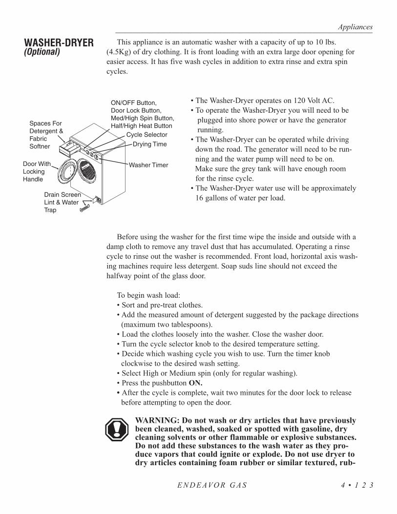
This appliance is an automatic washer with a capacity of up to 10 lbs.(4.5Kg) of dry clothing. It is front loading with an extra large door opening foreasier access. It has five wash cycles in addition to extra rinse and extra spincycles.
• The Washer-Dryer operates on 120 Volt AC.• To operate the Washer-Dryer you will need to be
plugged into shore power or have the generator running.
• The Washer-Dryer can be operated while driving down the road. The generator will need to be run-ning and the water pump will need to be on.Make sure the grey tank will have enough roomfor the rinse cycle.
• The Washer-Dryer water use will be approximately16 gallons of water per load.
Before using the washer for the first time wipe the inside and outside with adamp cloth to remove any travel dust that has accumulated. Operating a rinsecycle to rinse out the washer is recommended. Front load, horizontal axis wash-ing machines require less detergent. Soap suds line should not exceed thehalfway point of the glass door.
To begin wash load:• Sort and pre-treat clothes.• Add the measured amount of detergent suggested by the package directions
(maximum two tablespoons).• Load the clothes loosely into the washer. Close the washer door.• Turn the cycle selector knob to the desired temperature setting.• Decide which washing cycle you wish to use. Turn the timer knob
clockwise to the desired wash setting.• Select High or Medium spin (only for regular washing).• Press the pushbutton ON.• After the cycle is complete, wait two minutes for the door lock to release
before attempting to open the door.
WARNING: Do not wash or dry articles that have previouslybeen cleaned, washed, soaked or spotted with gasoline, drycleaning solvents or other flammable or explosive substances.Do not add these substances to the wash water as they pro-duce vapors that could ignite or explode. Do not use dryer todry articles containing foam rubber or similar textured, rub-
Appliances---------------------------------------------------------------------------------------------------------------------------------------------------------------------------------------------------------------------------------------------------------------------------------------------------------------------
E N D E AVO R G A S 4 • 1 2 3
WASHER-DRYER(Optional)

ber-like materials. Clean the lint screen after each use (if applicable),located in the top left corner on the back of the washer. Keep the arearound the exhaust opening and adjacent areas free from lint, dustand dirt accumulation.
The removable drain screen, which protects the pump from lint and foreignmatter, needs to be cleaned periodically. The frequency in which it is cleaneddepends upon the type of clothes that are washed. Cotton articles produce morelint than nylon articles. Under no circumstance should the drain screen beremoved while the machine is full of water. To clean the drain screen, on anempty machine, open the service door by pressing on the left hand side. Place acloth or shallow tray under the drain screen housing to catch any remainingwater that may drip out. It may be helpful to first set the machine to spin, thenremove the drain screen. This procedure reduces the amount of water released.Turn the drain screen counterclockwise and pull the drain screen out. Clean thescreen to remove any dirt and lint. To replace the screen slide it back into thehousing and turn it clockwise to secure. Close the service door.
NOTE: Check for water leaks before using the washer afterremoving and replacing the drain screen.
To winterize your Washer-Dryer follow the instructions below to avoid dam-age to your unit due to freezing:
1. With the unit off remove the wash filter to allow the water remaining(in the pump and drain hose) to be evacuated. Replace the filter.
2. Close the inlet shut-off valve located at the manabloc water system.3. Open the low point drains to drain all the water.4. In cold climates air should be used to blow out the system.5. Install the water pressure regulator on a short water hose. Connect it
to the water system. Use an air hose connector on the female end as this reduces pressure. Make sure one or more faucets are open.
If antifreeze is being used in the system follow these instructions:1. When putting antifreeze into the water system of your motorhome set
the washer to a warm/warm fill setting and allow water to flow into theunit until the antifreeze is detected.
2. Slowly advance the timer to a rinse cycle and allow the water to flowfor 10 seconds. Advance the unit to a spin cycle to remove the majorityof the water from the unit.
3. With the unit off remove the wash filter from the unit. This will allowthe water remaining in the pump and drain hose to be evacuated. Re-place the filter.
4. Any water remaining in the unit should contain antifreeze and be pro-tected from freezing.
Appliances---------------------------------------------------------------------------------------------------------------------------------------------------------------------------------------------------------------------------------------------------------------------------------------------------------------------
E N D E AVO R G A S4 • 1 2 4

Appliances------------------------------------------------------------------------------------------------------------------------------------------------------------------------------------------------------------------------------------------------------------------------------------------------------------------
E N D E AVO R G A S 4 • 1 2 5
NOTE: When placing the unit back into service allow theunit to operate for one complete cycle before doing laundryto ensure all antifreeze has been purged from the unit.
As you use the Washer-Dryer, occasionally wipe the exterior of the cabinetwith a damp cloth or sponge. Wipe dry with a soft cloth. Do not use polish onplastic trim. Clean the interior with one cup of chlorine bleach mixed with twocups of granular detergent. Run the washer through a complete cycle using thehot water. Repeat the process if necessary. Remove hard water deposits usingonly cleaners labeled as washer safe. Wipe the inside of the Washer-Dryer doorwith a soft cloth to remove any moisture. Periodically apply a thin coat of pastewax to the inner door, especially to the area which is immediately next to thedoor window. This will protect the door finish from laundry spills and discol-oration.
NOTE: Should the Washer-Dryer need removal for service,care should be taken as the Washer-Dryer weighs approxi-mately 185 lbs. Proper accommodations should be made toavoid risk of injury.

Appliances------------------------------------------------------------------------------------------------------------------------------------------------------------------------------------------------------------------------------------------------------------------------------------------------------------------
4 • 1 2 6E N D E AVO R G A S

GASINTRODUCTION • 129
ENTRY STEP • 129 Operation • 129
Tips • 130 Maintenance & Lubrication • 130
ENTRY DOOR • 131 SLIDE-OUT OPERATION • 132
Extending Room • 132 Retracting Room • 133
Awning - Slide-Out • 133Manual Override • 134
Manual Override - Bedroom Slide-Out • 135Preventative Maintenance • 136
ENTERTAINMENT CENTER - HOME • 136Front Television Lock-Out • 136
Television Antenna • 136Hook-ups - TV Cable, Computer & Telephone • 138
VCR & Bedroom Television (Optional) • 138Video Selector Box (Optional) • 138
Satellite System Prewire - DSS (Optional) • 139RADIO - DASH • 140
CITIZEN BAND (CB) RADIO PREWIRE (Optional) • 140
FANS • 141Bathroom Fan • 141
Exhaust Fan • 141Tips • 142
DOOR - SLIDING • 142AWNINGS • 143
Window Awning (Optional) • 143Patio Awning • 143
Awning - Automatic Carefree (Optional) • 146SOFA BED CONVERSION • 148
Sofa to Sleeper • 148Sleeper to Sofa • 148
DINETTE BED CONVERSION (Optional) • 148STORAGE - UNDER BED • 148
SECTION 5EQUIPMENT
5


This section covers the basic operation and care of various types of equipment found in the motorhome, most of which are provided for entertainment and comfort. More detailed information about specific equipment may be found in that particular manufacturer’s manual. Optionalequipment will also be discussed in this section which may not apply to allmotorhomes.
Detailed information with CAUTION or WARNINGinstructions for the various electronics, other than what isprovided in this section, can be found in the manufacturer’smanual.
The entry step features amber lighting under the step, automatic retractionwith the ignition key in the RUN position and a last out feature. Located to theleft, just inside the entry door, is the step switch.
Operating the Entry Step:1. With the entrance door open, turn the step switch on.2. Close the door. The step should retract and lock in the UP position.
The step light will remain on.3. Open the door. The step should extend and lock in the “down”
position with the under step light on. The step will retract whenthe door is closed.
4. The step is equipped with a power switch. When the switch isturned off, the step should remain in the extended position withthe door closed and the under step light off. Close the door andturn on the ignition switch. The step will retract for travel. To holdthe entry step in the retracted position proceed with the following:
• Turn the engine ignition switch off.• Wait 15 seconds and then turn the power step switch from off to
on, then back off again. The step will stay retracted until the step switch is turned ON, or the ignition switch is turned on.The retracted position is useful for high curbs or on boat ferries.
5. With the power switch off, the step extended, the entrance doorclosed and the ignition turned on the ignition override system willgo into effect and the step will automatically retract.
6. Turn the ignition off and open the door. The step will extend andlock in the “down” position. This is the “last out” feature. Whenthe ignition is on the step will always activate with the door move-ment, regardless of the power switch position.
Equipment------------------------------------------------------------------------------------------------------------------------------------------------------------------------------------------------------------------------------------------------------------------------------------------------------------------
E N D E AVO R G A S 5 • 1 2 9
INTRODUCTION
ENTRY STEP - Operation

If the step fails to operate:• Verify that the step switch is ON.• Check the main power supply for the step. A 20 amp auto reset 12
Volt DC circuit breaker is located on the rear run plate. • A magnetic door jam switch is used to control step operation. Use a
separate magnet to apply a “trigger” to the door jam switch. Rotatetest magnet to align polarity field.
• A five amp ATO blade fuse is used to illuminate the STEP OUTdash warning light. The fuse is located on the front run plate.
WARNING: If the motorhome is driven with the step in the extendedposition there is the possibility of causing major damage to both thestep and the motorhome.
Clean all mud, salt androad grime from the stepbefore lubricating. Lubricateall moving parts (bearings,pivot points, slides, clevis pinand the drive linkage ball)every 30 days with a goodquality heat and moistureresistant penetrating grease.Kwik Lube Spray Grease isspecially formulated to lubricateKwikee Electric Steps and itis also recommended forlubricating all moving parts.(Refer to the illustration.)
NOTE: Silicone lubricates and WD-40 are notrecommended as they have a tendency to evapo-rate and dry the mating surfaces which leavesthem vulnerable to the elements.
Equipment---------------------------------------------------------------------------------------------------------------------------------------------------------------------------------------------------------------------------------------------------------------------------------------------------------------------
E N D E AVO R G A S5 • 1 3 0
Tips
Maintenance & Lubrication

To keep the entry door in good condition and operating in the manner inwhich it was designed to operate, some routine maintenance items should beattended to on a regular basis. These items are as follows:
1. Strike Plate Adjustment:The door in the motorhome was installed and adjusted to a factorysetting. The position of the striker plate or bolt may change overthe course of time and settlement of the motorhome. The settingmay need to be adjusted to insure that your door operates smoothlyand efficiently. To adjust the strike plate, loosen the two Phillipshead screws holding the strike to the jamb system. Move the platein or out as needed to obtain a proper seal and closing force.Retighten the screws.
CAUTION: If you loosen the screws too far on the out-swing doors, the backer plate will release and drop downinto the door jamb. Should this happen, replace the shortscrews with a screw that is long enough to go through thejamb system and into the framework of the sidewall.
2. Locks:The key cylinder in your locks need to be lubricated on an annualbasis or as needed. Use a powdered graphite, not a petroleum product.Petroleum products gum up the cylinder and inhibits smoothoperation. Apply a light coating of white lithium grease to the faceof the lock bolt to obtain a smooth closing.
3. Hinges:The hinges on your door should be lubricated annually, or as needed,with any high-quality, dry spray lubricant.
4. Fiberglass Skin: To maintain their appearance and a long service life the door skinpanels should be washed and cleaned periodically. Cleaningremoves the accumulation of dust and dirt which can combinewith sunlight and wind to attack exposed surfaces, both chemicallyand abrasively.
Equipment------------------------------------------------------------------------------------------------------------------------------------------------------------------------------------------------------------------------------------------------------------------------------------------------------------------
E N D E AVO R G A S 5 • 1 3 1
ENTRY DOOR
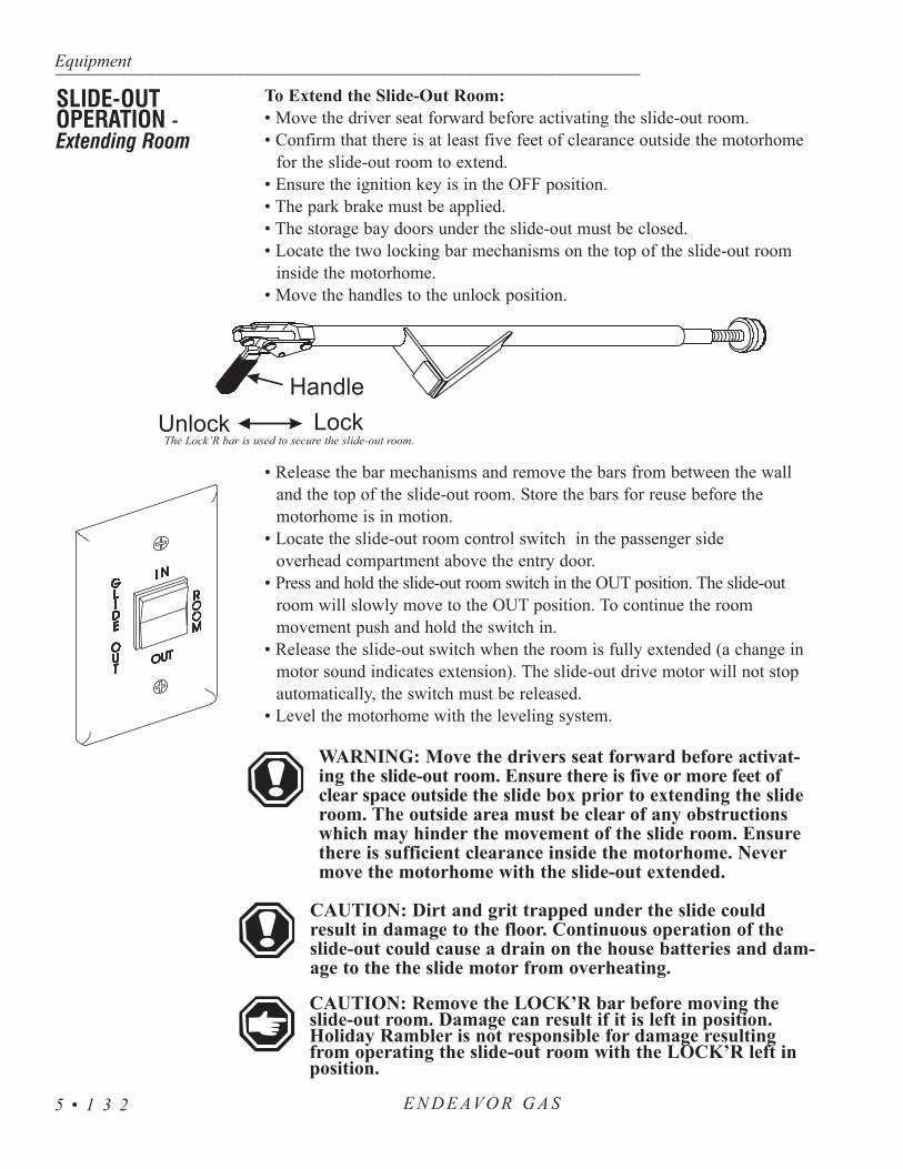
Equipment---------------------------------------------------------------------------------------------------------------------------------------------------------------------------------------------------------------------------------------------------------------------------------------------------------------------
5 • 1 3 2
To Extend the Slide-Out Room:• Move the driver seat forward before activating the slide-out room.• Confirm that there is at least five feet of clearance outside the motorhome
for the slide-out room to extend.• Ensure the ignition key is in the OFF position.• The park brake must be applied.• The storage bay doors under the slide-out must be closed.• Locate the two locking bar mechanisms on the top of the slide-out room
inside the motorhome.• Move the handles to the unlock position.
• Release the bar mechanisms and remove the bars from between the wall and the top of the slide-out room. Store the bars for reuse before the motorhome is in motion.
• Locate the slide-out room control switch in the passenger side overhead compartment above the entry door.
• Press and hold the slide-out room switch in the OUT position. The slide-outroom will slowly move to the OUT position. To continue the room movement push and hold the switch in.
• Release the slide-out switch when the room is fully extended (a change in motor sound indicates extension). The slide-out drive motor will not stop automatically, the switch must be released.
• Level the motorhome with the leveling system.
WARNING: Move the drivers seat forward before activat-ing the slide-out room. Ensure there is five or more feet ofclear space outside the slide box prior to extending the slideroom. The outside area must be clear of any obstructionswhich may hinder the movement of the slide room. Ensurethere is sufficient clearance inside the motorhome. Nevermove the motorhome with the slide-out extended.
CAUTION: Dirt and grit trapped under the slide couldresult in damage to the floor. Continuous operation of theslide-out could cause a drain on the house batteries and dam-age to the the slide motor from overheating.
CAUTION: Remove the LOCK’R bar before moving theslide-out room. Damage can result if it is left in position.Holiday Rambler is not responsible for damage resultingfrom operating the slide-out room with the LOCK’R left inposition.
SLIDE-OUTOPERATION -Extending Room
The Lock’R bar is used to secure the slide-out room.
E N D E AVO R G A S

NOTE: Slide-out room operation should be performed witha full air suspension system. It is not recommended toextend the slide room in snow, sleet, ice or freezing rain.There may be extensive damage resulting from the awningfreezing up.
To Retract the Slide-Out Room:• Check for sufficient clearance inside the motorhome before retracting
the slide-out room. • Clean the floor, if applicable, to ensure there is no dirt or grit that
could result in floor damage during slide-out retraction.• Press and hold the switch in the IN position. The slide-out room
will move slowly in. To stop the slide-out room before the roomreaches the IN position, release the switch. To continue the roommovement, push and hold the switch in. The motor will changetone when the slide-out room is fully extended.
• Release the switch. • After the slide-out room is completely retracted, locate the two
removable locking bar mechanisms. Place the bar mechanismsbetween the wall and the top edge of the slide-out room. TheLock’R has a built in spring to preset the tension. Move the handleto lock the position.
NOTE: Be sure you have sufficient clearance on the insideof the motorhome (drivers seat, etc.) before you retract theslide-out room. If your motorhome has ceramic tile floorensure the the floor is clean before you retract the slide-outroom. Dirt or grit that is trapped under the slide-out roomcan scratch the floor surface. Never move the motorhomewithout having the slide-out room retracted.
The motorhome is equipped with a slide-outawning that will automatically roll out with theslide room when it is extended. When the slideroom is extended the awning can then be rolled outcompletely as a window awning. The slide-outawning has two devices to help prevent the awningfrom “billowing” while traveling. The first device isa pair of anti-billow studs, which are located aboveeach end of the awning roller tube. If the awningcatches wind and begins to billow the awning metalwrap will contact the anti-billow stud leveringdownward and engaging with a plastic gearpreventing further unraveling of the awning material.
Equipment------------------------------------------------------------------------------------------------------------------------------------------------------------------------------------------------------------------------------------------------------------------------------------------------------------------
E N D E AVO R G A S 5 • 1 3 3
Awning - Slide-Out
Retracting Room

The second device uses two metal wind deflectors which arepositioned just below the awning. This helps prevent side windsfrom scooping under the awning and unwinding the awningmaterial.
CAUTION: The slide room and slide-outawning should be retracted during heavy windsor rain. Rain can be driven up under the slide-out awning and into the motorhome. The slide-out awning should be retracted in high windconditions as damage can occur to the awningor motorhome.
NOTE: At least five feet of clearance is neededbetween the side of the motorhome and anyobjects, such as trees or fences, to allow theslide room and slide-out awning to be fullyextended.
The slide-out room can be operated manually in the event of electrical problems.The slide-out room motor and gear assembly is located roadside in the largepass-through storage compartment. The lever on the motor must be moved tothe freewheel position.
The drive shaft can be moved using a 7/8 inch wrench. Once the slide-out roomhas been placed in the desired position place the motor lever in the service position.
NOTE: The slide-out room is heavy and may require severalpersons to push it into the retracted position.
Troubleshooting:The following can be used as a guide to assist you in the event of a slide
room malfunction.
Equipment---------------------------------------------------------------------------------------------------------------------------------------------------------------------------------------------------------------------------------------------------------------------------------------------------------------------
E N D E AVO R G A S5 • 1 3 4
Manual Override
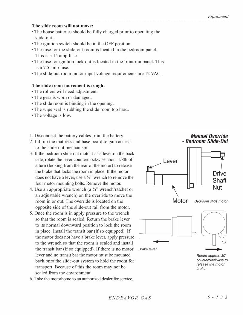
The slide room will not move:• The house batteries should be fully charged prior to operating the
slide-out.• The ignition switch should be in the OFF position.• The fuse for the slide-out room is located in the bedroom panel.
This is a 15 amp fuse.• The fuse for ignition lock-out is located in the front run panel. This
is a 7.5 amp fuse.• The slide-out room motor input voltage requirements are 12 VAC.
The slide room movement is rough:• The rollers will need adjustment.• The gear is worn or damaged.• The slide room is binding in the opening.• The wipe seal is rubbing the slide room too hard.• The voltage is low.
1. Disconnect the battery cables from the battery. 2. Lift up the mattress and base board to gain access
to the slide-out mechanism. 3. If the bedroom slide-out motor has a lever on the back
side, rotate the lever counterclockwise about 1/8th ofa turn (looking from the rear of the motor) to releasethe brake that locks the room in place. If the motordoes not have a lever, use a ½” wrench to remove thefour motor mounting bolts. Remove the motor.
4. Use an appropriate wrench (a ¾” wrench/ratchet oran adjustable wrench) on the override to move theroom in or out. The override is located on theopposite side of the slide-out rail from the motor.
5. Once the room is in apply pressure to the wrenchso that the room is sealed. Return the brake leverto its normal downward position to lock the roomin place. Install the transit bar (if so equipped). Ifthe motor does not have a brake lever, apply pressureto the wrench so that the room is sealed and installthe transit bar (if so equipped). If there is no motorlever and no transit bar the motor must be mountedback onto the slide-out system to hold the room fortransport. Because of this the room may not besealed from the environment.
6. Take the motorhome to an authorized dealer for service.
Equipment------------------------------------------------------------------------------------------------------------------------------------------------------------------------------------------------------------------------------------------------------------------------------------------------------------------
E N D E AVO R G A S 5 • 1 3 5
Manual Override - Bedroom Slide-Out
Bedroom slide motor.
Brake lever.
Rotate approx. 30°counterclockwise torelease the motorbrake.
The slide-out system has been designed to require very little maintenance.To ensure the long life of the slide-out system read and follow these simpleprocedures:
• The roof of the slide-out should be checked for debris such as pine needles, dirt, leaves, sticks, etc. If the slide-out has been out for a period of time, any debris left on the top may cause damage to the seals when being retracted. If debris is present wash with soap and water, then rinse.
• When the room is out visually inspect the inner slide rail assemblies. Check for excess build-up of dirt or other foreign material. Remove any debris that may be present.
• If the system squeaks or makes noise apply a coat of light weight oil to the drive shaft and roller areas. Remove any excess oil so dirt and debris do not build-up. Do not use grease.
CAUTION: Do not work on the slide-out system unless thebattery is disconnected.
NOTE: Do not leave the slide-out in the extended positionduring severe weather. Conditions such as high winds orheavy rain may cause damage to an extended slide-out.
NOTE: It is not recommended to extend the slide room insnow, sleet, ice or freezing rain. There may be extensive dam-age resulting from the awning freezing. In the event the slide-out room is extended in snow, sleet, ice or freezing rain con-ditions, it is recommended you clear the awning and ensurefree movement prior to retracting the slide room.
The motorhome is equipped with a remote control color television locatedabove the pilot seat. The outlet for front TV is controlled by the ignition switchso that the front TV can only be viewed while the vehicle is at rest. The TVoperates from 120 Volt AC power only, which can be provided by shore power,the generator or the inverter. Viewing time of the front TV from the inverterdepends on the state of charge of the house batteries and any additional 12 VoltDC lighting being used.
The television antenna is a manual crank up style antenna with built inelectronics which use 12 Volts DC to “boost” signal strength. Signals that areweak or fuzzy can be amplified by turning on the boost switch in the passengerfront overhead cabinet. The antenna and booster work together to provide thebest possible picture for most situations. Certain conditions occur when noamplification is needed and in fact may make the picture worse. The television
Equipment---------------------------------------------------------------------------------------------------------------------------------------------------------------------------------------------------------------------------------------------------------------------------------------------------------------------
E N D E AVO R G A S5 • 1 3 6
ENTERTAINMENT CENTER - HOMEFront Television Lock-Out
PreventativeMaintenance
Television Antenna

Equipment------------------------------------------------------------------------------------------------------------------------------------------------------------------------------------------------------------------------------------------------------------------------------------------------------------------
E N D E AVO R G A S 5 • 1 3 7
station will send a signal that resembles thewaves or rings of water from a rock throwninto a still pond. The radiating televisionsignal can hit an object such as a mountainand come back. The result one sees in thetelevision picture is a double image. Theantenna will receive a signal from the ini-tial pass, then receive an additional signalfrom the rebound resulting in a split ordouble image. In this case the picture maybe improved by no amplification or evenlowering the antenna.
NOTE: Do not move the motorhome with antenna in theraised position, it can be damaged by tree limbs or wires.
WARNING Before raising antenna make an outside, visualinspection for any obstructions or overhead electrical wires.Damage to the antenna, severe shock, personal injury ordeath can occur from inadequate clearance.
To Raise The Antenna:• Rotate the crank handle clockwise to raise the antenna (it is
approximately 14 ½ turns). • Pull down on the outside directional wheel and rotate the antenna
until the best picture is obtained. The directional wheel is springloaded.
WARNING: Do not raise a TV antenna near overheadelectrical wires as contact may cause serious injury ordeath. The motorhome must not be driven with the antennain a raised or partially raised position. Worm gear or wormbreakage may result.
To Lower The Antenna:• Pull down on the directional wheel and align arrows together.• Rotate crank handle counter clockwise lowering antenna fully into
the cradle. Make an outside visual inspection to ensure the antennais properly stowed.
Boost Operation:To boost the antenna signal to the TV or VCR use the boost switch. Turn this switch to the ON position. Turn the boost switch off when not in use.
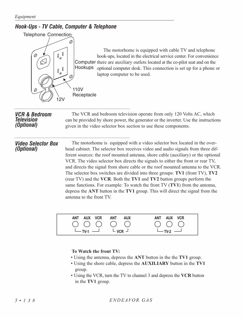
The motorhome is equipped with cable TV and telephonehook-ups, located in the electrical service center. For conveniencethere are auxiliary outlets located at the co-pilot seat and on theoptional computer desk. This connection is set up for a phone orlaptop computer to be used.
The VCR and bedroom television operate from only 120 Volts AC, whichcan be provided by shore power, the generator or the inverter. Use the instructionsgiven in the video selector box section to use these components.
The motorhome is equipped with a video selector box located in the over-head cabinet. The selector box receives video and audio signals from three dif-ferent sources: the roof mounted antenna, shore cable (auxiliary) or the optionalVCR. The video selector box directs the signals to either the front or rear TV,and directs the signal from shore cable or the roof mounted antenna to the VCR.The selector box switches are divided into three groups: TV1 (front TV), TV2(rear TV) and the VCR. Both the TV1 and TV2 button groups perform thesame functions. For example: To watch the front TV (TV1) from the antenna,depress the ANT button in the TV1 group. This will direct the signal from theantenna to the front TV.
To Watch the front TV:• Using the antenna, depress the ANT button in the the TV1 group.• Using the shore cable, depress the AUXILIARY button in the TV1
group.• Using the VCR, turn the TV to channel 3 and depress the VCR button
in the TV1 group.
Equipment---------------------------------------------------------------------------------------------------------------------------------------------------------------------------------------------------------------------------------------------------------------------------------------------------------------------
E N D E AVO R G A S5 • 1 3 8
Hook-Ups - TV Cable, Computer & Telephone
VCR & BedroomTelevision (Optional)
Video Selector Box(Optional)
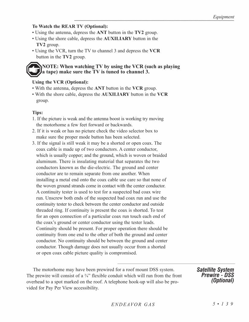
To Watch the REAR TV (Optional):• Using the antenna, depress the ANT button in the TV2 group.• Using the shore cable, depress the AUXILIARY button in the
TV2 group.• Using the VCR, turn the TV to channel 3 and depress the VCR
button in the TV2 group.
NOTE: When watching TV by using the VCR (such as playinga tape) make sure the TV is tuned to channel 3.
Using the VCR (Optional):• With the antenna, depress the ANT button in the VCR group.• With the shore cable, depress the AUXILIARY button in the VCR
group.
Tips:1. If the picture is weak and the antenna boost is working try moving
the motorhome a few feet forward or backwards.2. If it is weak or has no picture check the video selector box to
make sure the proper mode button has been selected.3. If the signal is still weak it may be a shorted or open coax. The
coax cable is made up of two conductors. A center conductor,which is usually copper; and the ground, which is woven or braidedaluminum. There is insulating material that separates the twoconductors known as the die-electric. The ground and centerconductor are to remain separate from one another. Wheninstalling a metal end onto the coax cable use care so that none ofthe woven ground strands come in contact with the center conductor.A continuity tester is used to test for a suspected bad coax wirerun. Unscrew both ends of the suspected bad coax run and use thecontinuity tester to check between the center conductor and outsidethreaded ring. If continuity is present the coax is shorted. To testfor an open connection of a particular coax run touch each end ofthe coax’s ground or center conductor using the tester leads.Continuity should be present. For proper operation there should becontinuity from one end to the other of both the ground and centerconductor. No continuity should be between the ground and centerconductor. Though damage does not usually occur from a shortedor open coax cable picture quality is compromised.
The motorhome may have been prewired for a roof mount DSS system.The prewire will consist of a ¾” flexible conduit which will run from the frontoverhead to a spot marked on the roof. A telephone hook-up will also be pro-vided for Pay Per View accessibility.
Equipment------------------------------------------------------------------------------------------------------------------------------------------------------------------------------------------------------------------------------------------------------------------------------------------------------------------
E N D E AVO R G A S 5 • 1 3 9
Satellite SystemPrewire - DSS
(Optional)

The dash radio is a tuner and a compact disc player. It holds up to eighteenpreset FM stations and six AM stations. Other features are an attenuate mode,loudness control, a clock and autoseek tuning. The compact disc player featuresare fast forward and reverse, random track play, repeat and pause. The radiopower can be turned off from two different locations.
Tips:1. If the radio does not function check the house battery cut-off switch
to make sure it is on. Check either of the radio power switcheslocated at the dash panel and in the bedroom.
2. The LCD display may become difficult to read at temperatures at orbelow 41° F.
For detailed information and operating instructions on thestereo and CD player system refer to the manufacturer's manu-al.
The motorhome may have been pre-wired for a Citizen Band (CB) Radio. Atwo pin connector is labeled Citizen Band Radio for future installation. The redwire is fused at a two amp connection in the front distribution panel. Theground wire, white in color, is connected to the chassis frame.
Equipment---------------------------------------------------------------------------------------------------------------------------------------------------------------------------------------------------------------------------------------------------------------------------------------------------------------------
E N D E AVO R G A S5 • 1 4 0
RADIO - DASH
CITIZEN BAND (CB)RADIO PREWIRE(OPTIONAL)

The motorhome is equipped with roof air vents whichare manually operated. The vent is opened or closed bysimply turning the crank handle in the desired direction.The fan, which is for ventilation only, will not help coolthe motorhome, and is operated by pushing the smallpower button. The vent must be opened before using thepower fan. To close the power air vent push in the powerbutton to stop the fan and close the vent.
The fan is a three speed fan with a 0 or OFF position. The fan will eitherpull in air or extract air from the motorhome. There are three controls locatedon the ceiling vent fan. The knurled knob is used to open the vent cover. Therotary knob will select the operating speed of the fan.
The IN/OUT switch controls the direction of the fan rotation. When thevent cover is opened approximately two inches the fan motor will operate.Thevent cover lid must be manually controlled during normal operations by theknurled knob.
To Operate The Fan:• Open the vent cover using the
OPEN/CLOSE knob.• Select the desired fan direction to
IN/OUT.• Select the desired fan speed on the
Speed Control dial: 0 = OFF.1 = LOW. 2 = MEDIUM. 3 = HIGH.
NOTE: If the speed switch is in the “0” position the fanoperates only as a vent.
Equipment------------------------------------------------------------------------------------------------------------------------------------------------------------------------------------------------------------------------------------------------------------------------------------------------------------------
E N D E AVO R G A S 5 • 1 4 1
FAN - Bathroom Fan
Exhaust Fan

• To keep condensation from accumulating open the vent fan lidsslightly to help the air circulate. Condensation occurs naturallyfrom fluctuations in interior and exterior temperatures, humidityand dew point changes, steam from cooking or boiling largeamounts of water on the cooktop. Shower usage also producescondensation.
• If the fan fails to operate check for a blown fuse either in thedomestic fuse panel or the 6 amp fuse on the fan.
• To clean the screen remove the eight screws holding it in place.Wash the screen using a non-abrasive soap and water. Re-install thescreen and tighten the screws.
• Keep all the vents closed when using the Fantastic Fan Vent. Directthe airflow by slightly opening the window(s) on the shaded sideof the motorhome to obtain the maximum air flow, especially onhot, sunny days. Close all the roof vents. The area between theopen window(s) and the Fantastic Vent supplies the maximum airflow and providing the most comfort.
NOTE: Do not leave the vent cover open while themotorhome is stored or unattended for extended periods oftime. High winds other unusual conditions or obstructionsmay prevent closing. The resulting leakage could cause seri-ous damage.
The sliding pocket door uses two rollers at the top of eachdoor. During the life of the motorhome the sliding door mayneed adjusting. The sliding pocket door can be adjusted to closetight against the wall. Locate the small wrench and turn theadjusting screw upward or downward.
If, for any reason, the pocket door needs to be removedlocate the portion that is secured to the top of the pocket doorand rotate the small lever outward to release the latches.
The pocket door rollers should be lubed with just a drip of oil once ayear to help increase the life of the rollers and improve the sliding of thedoor.
Equipment---------------------------------------------------------------------------------------------------------------------------------------------------------------------------------------------------------------------------------------------------------------------------------------------------------------------
E N D E AVO R G A S5 • 1 4 2
Tips
DOOR - SLIDING

To Extend Awning:1. Catch the loop of the pull strap with the awning rod.2. Pull the awning to fully extend the reel assembly and
the side arms away from the motorhome.3. Hook the pull strap on to the side strap hook. 4. Remove the awning rod from the pull strap and
store it.
To Retract Awning:1. Hook the awning rod on to the pull strap. 2. Remove the pull strap from the side strap hook and
slowly allow the awning to retract.3. Remove the awning rod from the pull strap loop
and store it.
To Unlock The Awning:1. Loosen the black locking knobs.2. Lift the arm storage locks
located on each upper arm tothe unlock position. Slide thebrake control, located on thefront arm only, to the full up(unlock) position.
To Extend The Patio Awning:1. Hook the loop of the center pull strap with the pull wand and draw
the awning away from the motorhome to the desired extension.Slide the center pull strap to one end of the awning and store it.
2. Slide the inner rafters to the top of each arm and push outward tothe tension canopy. Tighten the black locking knobs.
3. Raise the arm extension lock handles and slide the awning upward.Lower the lock handles and move the awning arm upward ordownward to lock the detent into the hole. First, raise the lockhandles on the main side. Next, raise the lock handles to the entrydoor. Go to the other awning arm and do the same. Make sure theawning is straight.
Equipment------------------------------------------------------------------------------------------------------------------------------------------------------------------------------------------------------------------------------------------------------------------------------------------------------------------
E N D E AVO R G A S 5 • 1 4 3
AWNINGS- Window Awning (Optional)
PatioAwning

To Retract The Patio Awning:Retract the arms and lower the awning until the arms rest on the lower stop bolts
and lock into position. Loosen the two black locking knobs. Release the locking tabon the end of the awning leg. Slide the pull strap to the center of the awning whileholding on to the strap. Allow the awning to roll up to the stored position.
• Snap the arm storage locks into the down position and tighten the black locking knobs.
• Verify that the brake control is in the locked or closed position.
CAUTION: When the awning is at full extension do not allowthe awning to snap back into the retracted position. Personalinjury or damage to the awning or motorhome may occur.
Rain Release Setting: After the awning has been extended choose the rain release position to pre-
vent water build up on the awning. To position the awning in the rain releasesetting lower one arm of the awning and leave the other arm in the normal posi-tion. This will create enough of a slope for adequate water run off.
Using The Carport Feature:To safely use the carport feature:1. Extend the braces and lock them into the end of
the side arms. Tighten the black knobs.2. Extend the awning as described under
“To Extend Awning.”3. Unlatch the bottom of the rear arm by pushing in on the
lock handle on the arm bracket. Swing the arm away from the motorhome to an upright position.
4. Raise the rear arm extension lock handle all the way up to the unlocked position. Extend the arm to position the awning at the desired height and lower the lock handle to lock the arms in place.
5. Drive the stakes through the bottom holes in the arm.6. Repeat instructions 1 through 5 for the front arm
extension lock handle.
NOTE: To move the awning out of the carport positionreverse the above steps.
Equipment---------------------------------------------------------------------------------------------------------------------------------------------------------------------------------------------------------------------------------------------------------------------------------------------------------------------
E N D E AVO R G A S5 • 1 4 4
Securing The Awning For Travel:Before traveling check the following:1. The awning is fully retracted against the sides of the motorhome.2. The black locking knobs are tightened.3. The storage locks are down and in the locked position.4. The brake control is in the full down (locked) position and no red
warning is showing.5. The bottom of the front and rear arms are latched properly into
the bottom brackets.6. The catch rod is stored away.
Care and Maintenance:Washing:On a monthly basis, loosen hardened dirt and remove dust fromthe awning with a dry, medium bristle brush. Thoroughly rinseboth the top and bottom with a hose. Wash both sides of theawning using a quality vinyl cleaner solution and an awningbrush. (Washing the awning can be made easier with use ofawning maintenance products.) Saturate the fabric with the cleaningsolution and leave it on for 15-20 minutes. If necessary, reapplythe solution to keep the fabric saturated. Rinse the awning thoroughly.Repeat, if necessary, until most of the stains disappear.
Water Leaks: If leaking occurs after washing it generally results from insufficient rinsing. If water drips through the needle holes in the stitching use a commercial seam sealer which is available in canvas and trailer supply stores. Paraffin wax may also be applied to the top of the seams. As the awning “weathers” these holes will normally seal themselves.
It is normal for slight leakage to occur through the fabric where water isallowed to accumulate or pocket on the fabric. See “Storm Precautions” forinformation on the awning settings for proper water drainage. Sometimes soapor chemical residue, such as from active agents in insect fog or sprays, can“wet” the fabric so that it appears unable to repel water. Rinse the fabricthoroughly and test to see if it is water repellent after it dries. If leakage contin-ues after repeating the washing and thoroughly rinsing please contact CarefreeAwning Magic concerning further maintenance.
Storm Precautions: The warranty does not cover damage caused by acts of God; therefore, steps should be taken to prevent damage from occurring due to wind, rain or storms. If you are leaving or retiring for
Equipment------------------------------------------------------------------------------------------------------------------------------------------------------------------------------------------------------------------------------------------------------------------------------------------------------------------
E N D E AVO R G A S 5 • 1 4 5

the night close the awning. This takes only a few minutes and it gives the best protection for the awning. If closing the awning is not possible at the time, lower both ends of it as far as possible to create a sufficient slope for water run-off. One end may be lowered to sufficiently divert the water if the awning is being monitored.
Water weighs 8.33 pounds per gallon. The awning was not made to with-stand the 500 to 700 pounds that could accumulate. It is best not to subject theawning and the motorhome to the needless strain.
NOTE: Allow the awning material to thoroughly dry beforerolling the awning up. Metal surfaces should be cleaned withsoapy water and thoroughly rinsed.
The Carefree One Touch automatic awning requires only“finger tip” operation. A key lock on the One Touch switchpad is provided to prevent accidental deployment of theawning while the motorhome is in motion. The key is remov-able in the lock or unlock position.
Gas filled struts keep the awning fabric tight at anyextended position. The 12 Volt DC motor for the One Touchawning uses approximately 15 amps while in operation.
To Extend the Awning:• Verify all persons and objects are clear from the extend path of the
awning and related hardware.• Turn the One Touch key to the ON position. • Depress and hold the momentary switch to EXTEND. Motor will
automatically stop at full extension.• Allow 14 seconds for awning to reach full extension.• Extension distance or fabric tension is adjusted by toggling between
RETRACT and EXTEND.• Turn the One Touch key to the OFF position.
CAUTION: The patio awning requires nine feet of lateralclearance from the side of the motorhome. This distance willallow the awning to reach full extension. The One Touchpatio awning was not designed with a carport feature or arain release setting. The awning should be retracted if themotorhome is left unattended or high wind conditions exist.Otherwise, wind damage to the awning may occur.
Equipment---------------------------------------------------------------------------------------------------------------------------------------------------------------------------------------------------------------------------------------------------------------------------------------------------------------------
E N D E AVO R G A S5 • 1 4 6
Awning - Automatic (Optional)

NOTE: It is not required to have the awning at full exten-sion. Awning may be stopped at any time of extension orretraction by releasing the momentary switch.
NOTE: Some models may require that the ignition key beturned to accessory or the ignition run position.
To Retract the Awning:• Verify all persons and objects are clear from the retract path of the
awning and related hardware. • Turn the One Touch key to the ON position. • Depress and hold the momentary switch to RETRACT. The motor
will automatically stop at full retraction.• It takes approximately 14 seconds for the awning to travel from the fully
extended position to the fully retracted position. • Turn the One Touch key to the OFF position to avoid accidental
deployment of the awning while the vehicle is in motion.
Tips:If the awning fails to retract or extend:
• Verify the One Touch key is in the ON position.• The house battery cut off switch is in the ON position.• The house battery voltage is at 12 Volts or above.• Verify proper electrical connection from the awning motor to the side of
the motorhome.
Emergency Retract Procedure:If the One Touch awning fails to retract and proper DC voltages have been
verified the One Touch awning has two emergency methods of alternatelyretracting the awning:
1. Two exposed electrical studs are mounted externally at the forward end of the awning at the motor assembly. An alternate 12 Volt DC positive and negative supply may be applied to these connections. If awning fails to move reverse the polarity of the alternate supply leads.
2. On the motor assembly, mounted externally at the forward end of the awning, is an opening. Insert a 9/64” Allen hex wrench. Using an electric drill wind the awning to the retract position.
CAUTION: When using an alternate method to operate theawning use extreme care to keep appendages, hair or looseclothing away from exposed rotating hardware.
Equipment------------------------------------------------------------------------------------------------------------------------------------------------------------------------------------------------------------------------------------------------------------------------------------------------------------------
E N D E AVO R G A S 5 • 1 4 7

The sofa will convert easily into a bed. The sofa comes equipped with safetybelts and these should be used if occupied during travel.
• Raise the sofa seat base until seat base and backrest form a V shape by lifting up from the center of sofa just below the seat cushions.
• Push down on seat base until the seat base and backrest are flat. • Fold seat belts out of the way.
• Lift the seat base up until seat and back rest are in a V shape.• Push down on seat base.
• The booth dinette easily converts into a bed. • Lift seat cushions to an angled vertical position.• With a firm grip, lift front edge of the table approximately six inches and
push table leg lock to side. • Swing the table leg up and lock into a horizontal position. • Continue lifting table until table stays are clear of retainers. Pull
outward and lower table down. • Use both seat cushions and one back cushion for a mattress. Leave one
back cushion in a vertical position.
WARNING: Do not occupy the booth dinette, if NOTequipped with safety belts, or the dining chairs while themotorhome is in motion. To avoid personal injury to occu-pants in case of a crash or sudden stop, chairs must be storedin an enclosed area or secured with tie down straps while themotorhome is in motion.
To use the storage compartment located under the bed, locate and unlock thebed deck latches. Lift up the bed by the front edge of the mattress platform. Gasstruts hold the mattress and platform open.
NOTE: Do not over stress gas struts by rapidly opening orclosing the bed access cover. This action can damage thestruts or mounts. In extreme cold gas struts may not hold themattress platform in the open position.
Equipment---------------------------------------------------------------------------------------------------------------------------------------------------------------------------------------------------------------------------------------------------------------------------------------------------------------------
E N D E AVO R G A S5 • 1 4 8
SOFA BEDCONVERSION
Sofa to Sleeper
Sleeper to Sofa
DINETTE BEDCONVERSION(Optional)
STORAGE- UNDER BED

Equipment------------------------------------------------------------------------------------------------------------------------------------------------------------------------------------------------------------------------------------------------------------------------------------------------------------------
E N D E AVO R G A S 5 • 1 4 9
NOTES

Equipment------------------------------------------------------------------------------------------------------------------------------------------------------------------------------------------------------------------------------------------------------------------------------------------------------------------
5 • 1 5 0E N D E AVO R G A S

6INTRODUCTION • 153
MONITOR PANEL - Measurement & Calibration • 153WATER TANK - FRESH WATER FILL • 154
WATER TANK - FRESH GRAVITY FILL • 154WATER - CITY HOOK-UP • 155
WATER PUMP • 155Water Pump - Troubleshooting • 156
WATER FILTER (OPTIONAL) • 157WATER SYSTEM - Troubleshooting • 158
WATER SYSTEM - Disinfecting Fresh Water • 158TANK CAPACITIES - Chart • 159
WASTE WATER SYSTEMS - Waste Drain & Sewage Tanks • 160What Not to Put in Waste Holding Tanks • 160
Proper Waste Disposal • 160Connecting to Available Sewer Hook-Up • 161
TOILET - Operating Instructions • 161Cleaning • 161
Maintenance • 162Drain Traps & Auto Vents • 162
Draining the Waste Holding Tanks • 162What to Put into the Holding Tanks - Black Tank • 163What to Put into the Holding Tanks - Grey Water • 164
COLD WEATHER USE • 164Bay Heater (Optional) • 165
Cold Weather Package (Optional) • 165WINTERIZING - Using Air Pressure • 165
WINTERIZING - Fresh Water System Using Nontoxic Antifreeze • 166
GASSECTION 6
WATER SYSTEMS

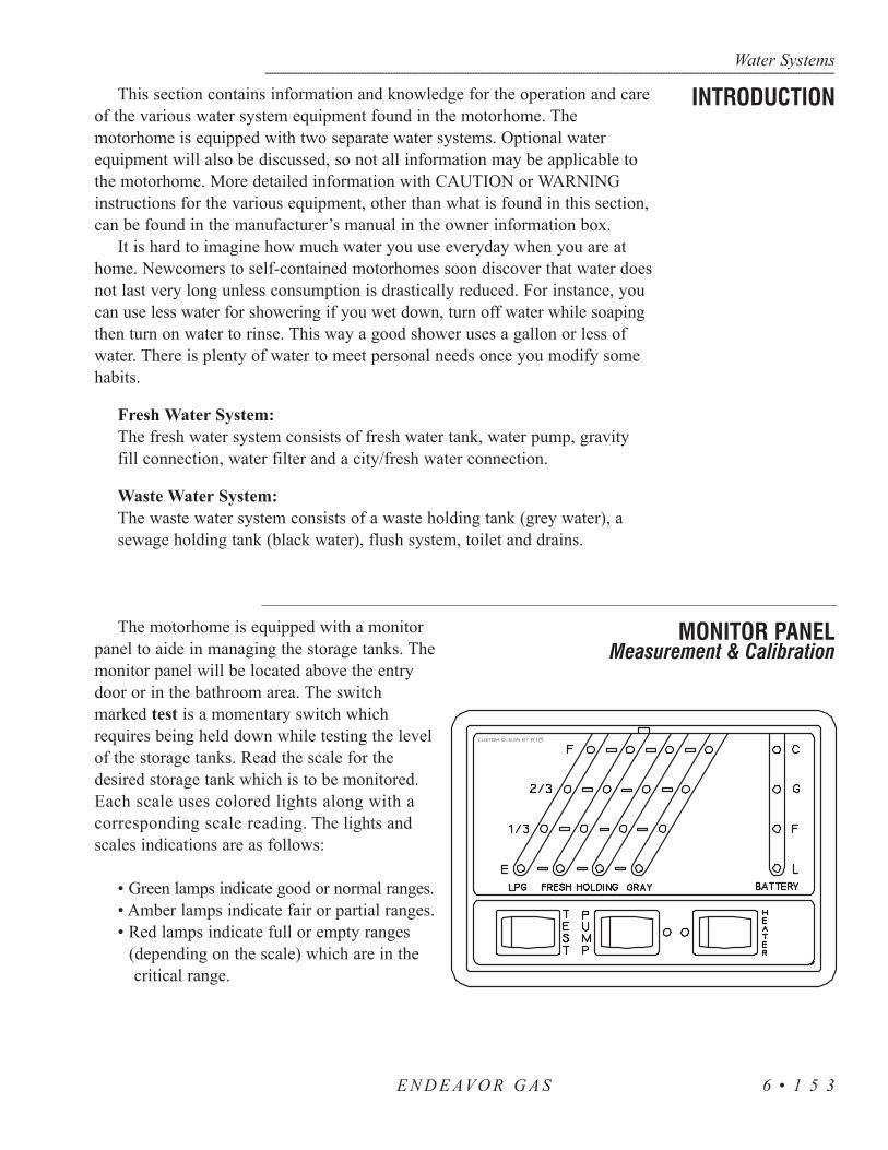
This section contains information and knowledge for the operation and careof the various water system equipment found in the motorhome. Themotorhome is equipped with two separate water systems. Optional waterequipment will also be discussed, so not all information may be applicable tothe motorhome. More detailed information with CAUTION or WARNINGinstructions for the various equipment, other than what is found in this section,can be found in the manufacturer’s manual in the owner information box.
It is hard to imagine how much water you use everyday when you are athome. Newcomers to self-contained motorhomes soon discover that water doesnot last very long unless consumption is drastically reduced. For instance, youcan use less water for showering if you wet down, turn off water while soapingthen turn on water to rinse. This way a good shower uses a gallon or less ofwater. There is plenty of water to meet personal needs once you modify somehabits.
Fresh Water System:The fresh water system consists of fresh water tank, water pump, gravity fill connection, water filter and a city/fresh water connection.
Waste Water System:The waste water system consists of a waste holding tank (grey water), a sewage holding tank (black water), flush system, toilet and drains.
The motorhome is equipped with a monitorpanel to aide in managing the storage tanks. Themonitor panel will be located above the entrydoor or in the bathroom area. The switchmarked test is a momentary switch whichrequires being held down while testing the levelof the storage tanks. Read the scale for thedesired storage tank which is to be monitored.Each scale uses colored lights along with acorresponding scale reading. The lights andscales indications are as follows:
• Green lamps indicate good or normal ranges.• Amber lamps indicate fair or partial ranges.• Red lamps indicate full or empty ranges
(depending on the scale) which are in the critical range.
Water Systems------------------------------------------------------------------------------------------------------------------------------------------------------------------------------------------------------------------------------------------------------------------------------------------------------------------
E N D E AVO R G A S 6 • 1 5 3
INTRODUCTION
MONITOR PANELMeasurement & Calibration

1. Check to make sure the fresh water tank drain valve located on roadside in the service center is in the closed position.
2. Connect the hose labeled for potable water to the water source. The water hose from the source to the motorhome sometimes will not have a pressure regulator inline. On a hot day the hose may expand and burst from water pressure within the water hose.
3. Remove white plug in the end of the pressure regulator. 4. Connect the water hose to the City water inlet. 5. The knife valve should be in the Fresh Water position. 6. Turn on the water at the water source. The water should be
audible as the fresh water tank fills. 7. Locate the monitor panel. Lift the cabinet door and locate
the switch marked test. The switch is a momentary switch that requires the switch to be held in position while testing the level in the fresh water tank. Read the scale as the fresh water tank is filling. When the 2/3 tank light illuminates it should not take much longer to finish filling the tank. Do not leave coach unattended while filling the fresh water tank. The light marked “F” should start to blink as a warning that the fresh water tank is almost full. Return to the service center. When the fresh water tank is full water will come out an overflow tube under the coach on the driver’s side.
8. Turn off water supply as quick as possible.
The gravity fill inlet allows fluids to be introduceddirectly into the fresh water tank. When dry campingwater can be poured directly from a container into thefresh water tank. The gravity fill inlet can be used to pourdisinfecting solution into the fresh water tank or whenusing potable RV antifreeze to winterize the fresh watersystem. Use only potable water sources, solutions anddelivery systems when using the gravity fill inlet.
Filling the Tank:1. Unscrew fill cap taking care to keep cap and inlet clean.2. Insert potable water hose into inlet.3. Fill tank until water overflows from inlet.
NOTE: When filling tank do not leave hoseunattended.
Water Systems---------------------------------------------------------------------------------------------------------------------------------------------------------------------------------------------------------------------------------------------------------------------------------------------------------------------
E N D E AVO R G A S6 • 1 5 4
WATER TANK - FRESH WATER FILL
WATER TANK - FRESH GRAVITY FILL
The valve must be in the Fill Tank position(as pictured) for fresh water fill.
Gravity Fill Tank.

When connecting the motorhome to fresh water use ahose manufactured and labeled for potable water to insurethat the hose will not flavor the water.
1. Remove white plug in the end of the water inlet. 2. Connect water hose to the city water inlet. 3. Knife valve handle should be in the position shown
in the picture.4. Turn on water at water source. 5. The water pump can either be in the OFF position or
in the ON position. It will not affect the water pumpto leave it on.
6. The fresh water connection has a built in pressureregulator and a one way check valve that protects themotorhome to 45 lbs.
7. You may need to open each faucet one at a time torid any trapped air inside the pipes.
CAUTION: Some water sources develop high water pres-sure, particularly in mountainous regions. High water pres-sure is anything over 55 psi (pounds per square inch).Excessive water pressure may cause leaks in water linesand/or damage the water heater. The coach does come with apressure regulator.
The water pump is used to pressurize the fresh water system whenit is not connected to city water. The water pump is totally automaticand self- priming, operating on demand as water is used. The pressureequalizer tank relieves the water pump from cycling when a smallamount of water is used. The water pump is located in a storagecompartment of the motorhome.
WARNING: Before leaving the coach for extendedperiods of time (i.e. overnight or longer) be surethat the city water and all water pumps have beenturned off. Damage from neglect will be responsibilityof the owner and not Holiday Rambler.
To operate the water pump push on switch and watch for thegreen light to stay on. The remote switches are located in the bath-room on the control panel next to the entrance door and on the out-side water control panel.
Do not allow the pump to run when the fresh water supply tank isempty. Continued operation with a dry tank may open an electricalcircuit and/or damage the water pump.
Water Systems------------------------------------------------------------------------------------------------------------------------------------------------------------------------------------------------------------------------------------------------------------------------------------------------------------------
E N D E AVO R G A S 6 • 1 5 5
WATER - CITY HOOK-UP
WATER PUMP
The valve must be in the Local Supply position(as pictured) for city water fill.

Water Systems---------------------------------------------------------------------------------------------------------------------------------------------------------------------------------------------------------------------------------------------------------------------------------------------------------------------
E N D E AVO R G A S6 • 1 5 6
To start pump after unhooking city water supply or first time use proceed as follows:
• Fill the fresh water tank.• Open all valves and faucets except the drain valves. This
includes hot and cold water valves, all faucets andshower.
• Turn the water pump on and wait for the water lines andthe hot water tank to fill.
• Close each faucet when it delivers a steady stream ofwater (cold water faucets first).
Vibration induced by road conditions can cause the plumbing or pumphardware to loosen. Check for system components that are loose. Manysymptoms can be resolved by simply tightening the hardware. Check thefollowing items along with other particulars of the system.
The water pump will not start/blows the circuit:• Check the electrical connections, fuse, breaker, main switch
and ground connection.• Is the motor hot? The thermal breaker may have
triggered. It will reset when cool.• Is the voltage present at the switch? Bypass the
pressure switch.• Does the pump operate?• Check the charging system for correct voltage and
check the pump for the proper ground connection.• Look for an open or grounded circuit or motor. • Check for seized or locked diaphragm assembly (water frozen).
The water pump will not prime/sputters (No discharge/motor runs):• Is the strainer clogged with debris?• Is there water in the tank, or has air collected in the hot water heater?• Is the inlet tubing/plumbing sucking in air at plumbing connections
(vacuum leak)?• Check for proper voltage with the pump operating.• Look for debris in the pump inlet/outlet valves or dry/swollen valves. • Check the pump housing for cracks or loose drive assembly screws.
Water Pump -Troubleshooting

The water pump will not shut-off/runs when the faucet is closed:• Check to see if the fresh water tank fill valve is
completely closed.• Check output side (pressure) plumbing for leaks and
inspect for a leaky toilet or valves. • Look for loose drive assembly or pump head screws. • Are the valves or the internal check valve held open by
debris or is the rubber swollen?
The water pump is noisy or rough in operation:• Check for plumbing which may have vibrated loose. • Does the mounting surface multiply noise (flexible)?• Check for mounting feet that are loose or compressed
too tight.• Look for loose pump head to motor screws (three long
screws).• Is the motor with the pump head removed? Is noise
coming from the motor or pump head?
The water pump is rapid cycling:• Look for restrictive plumbing/flow restrictors in the
faucets or shower heads.
Servicing the Filter:The water filter is located under the
galley sink, and may have beeninstalled in the motorhome without itscartridge.
The units ADC Cartridge is easilyinstalled by following the simpleinstructions on the cartridge wrapper. Afresh replacement cartridge is neededwhen the flow of water from the faucetbecomes too slow for convenience. Howoften will this occur? That depends onhow cloudy the unfiltered water is andhow much water is used.
Each time water passes through thewater filter dirt particles are trapped andheld in the tiny pores of the micro-purecoating on the filtering element insidethe cartridge. As the cartridge actively
Water Systems------------------------------------------------------------------------------------------------------------------------------------------------------------------------------------------------------------------------------------------------------------------------------------------------------------------
E N D E AVO R G A S 6 • 1 5 7
WATER FILTER(Optional)

removes the impurities from the water its microscopically small pores slowlyfill up and the amount of water flowing from the cartridge gradually lessens.
When the flow of water from the water filter becomes too slow for convenienceit should be serviced. If the cartridge is not changed, eventually the flow willstop entirely. Even when a decreasing flow does not demand it, at least one car-tridge change a year is recommended for reliable performance from the WaterFiltration System.
Water system problems and leaks usually fall into two categories: systemproblems and problems caused by improper use or lack of attention. Theseproblems usually stem from improper winterizing, poor maintenance, roadvibration and campsite water pressure variations. Check all plumbing connectionsfor leaks at least once a year. If the water pump runs when a faucet is not open,check for a water leak. Be sure the tank drain valves are closed. If the systemcontinues to leak take the motorhome to an authorized dealer for service.
Disinfecting the water system with chlorine bleach (superchlorination)protects you and your family from bacteriological or viral contamination fromany common water source.
You should disinfect the water system:• If the motorhome is new.• If the motorhome has not been used in a long time.• Every three months.
NOTE: An independently operated water pump with gardenhose connections and a container to hold prepared solutionmay be desired to perform this task. The gravity fill may alsobe used to perform the task. Remove cap off the gravity fill.Add the solution to the fresh water tank. When finishedsecure the gravity feed cap.
Use following procedure to disinfect water system:• Remove the filter element from the filter and reassemble the filter without
the elements (see "Filter").
• Prepare a chlorine bleach solution using 1 gallon water and 1/4 cup of chlorine bleach. Use 1 gallon of solution for every 15 gallons of tank capacity. Example: Add 2-2/3 gallons solution to a 40 gallon tank. Add 4-2/3 gallons solution to a 70 gallon tank. Add 6-2/3 gallons to 100 gallon tank. This mixture puts a 50 ppm (parts per million) residual in the water system. This concentration will act as a quick-kill dosage for harmful
Water Systems---------------------------------------------------------------------------------------------------------------------------------------------------------------------------------------------------------------------------------------------------------------------------------------------------------------------
E N D E AVO R G A S6 • 1 5 8
WATER SYSTEM - Troubleshooting
WATER SYSTEM -Disinfecting Fresh Water

bacteria, viruses and slime-forming organisms. Concentrations higher than 50 ppm may damage the water lines and/or tanks.
• Drain the fresh water tank. Close the drain and pump the solution (if desired) into the fresh water tank using an independently operated pump and a garden hose connected to City Water Hook-Up on the water controlpanel. It can be poured into the fresh tank using the gravity fill and a funnel. Open each faucet, in turn, and run the water until you smell a distinct chlorine bleach odor. Do not forget the hot water, tub and shower faucets.
• Allow the system to stand for four hours.
• Drain the system and flush with fresh water. The drain is located in the outside water control compartment. Install new water filters. Flush with fresh water repeatedly, if necessary, until no chlorine bleach taste or smell is left in the water system.
Water Systems------------------------------------------------------------------------------------------------------------------------------------------------------------------------------------------------------------------------------------------------------------------------------------------------------------------
E N D E AVO R G A S 6 • 1 5 9
TANK CAPACITIES - CHART
MODELS 35SBD 35PBD 35WGS 36SGS 36PBD 36WGS
Water Heater 6 Gal. 6 Gal. 6 Gal. 6 Gal. 6 Gal. 6 Gal.
Grey Tank 45 Gal. 45 Gal. 43 Gal. 45 Gal. 45 Gal. 45 Gal.
Black Tank 45 Gal. 45 Gal. 45 Gal. 45 Gal. 45 Gal. 45 Gal.
Fresh Tank 67 Gal. 67 Gal. 67 Gal. 70 Gal. 55 Gal. 70 Gal.
LP Tank 32.9 Gal.
32.9 Gal.
32.9 Gal.
32.9 Gal.
32.9 Gal.
32.9 Gal.
TANK CAPACITIES (Approximate Gallons)

The waste drainage system is designed to provide adequate and safe storageand/or discharge of waste materials. All materials used in the fabrication andinstallation of the system are tested by a nationally recognized testing laboratory.The entire fabricated waste system is factory tested in accordance withAmerican National Standards Code A119.2. The drainage system uses ABSplastic piping and fittings for its connection to the sinks, shower, toilet andholding tanks which provide for the proper drainage to an outside termination.The motorhome should be reasonably level for optimum operation of the sys-tems. Two separate waste water systems are in the motorhome: one for wastewater (grey water) and one for sewage waste (black water). Each has its ownstorage tank and control valve. Both systems empty through a sewer drain hose.When the motorhome is traveling both holding tanks should be empty or lessthan half full.
• Do not use strong or full strength detergents to deodorize and disinfect. Use odor control chemicals made especially for holding tanks.
• Do not put automotive antifreeze, ammonia, alcohol or acetone in holding tanks. Some chemicals will dissolve plastic.
• Do not put large table scraps in the tanks. They could get stuck in or damage the valve seals.
• Do not flush facial tissues. They are treated chemically to strengthen them and will not dissolve like toilet paper. Special holding tank tissues are available at most RV supply stores. White toilet paper dissolves faster than colored papers.
Most State Parks have strict regulations about discharging wastes except intoauthorized disposal systems. Dumping raw sewage from toilet holding tanks,except at authorized dumping stations, is universally prohibited.
Most National, State and private parks have either a central dump facility orcampsite hook-up for sewage. Many of the modern rest areas along the inter-state now have dump stations available. You will find a list of dumping stationsfrom coast to coast in Woodall’s Campground Directory, Trailer Life’s RVCampgrounds and Services Directory, Rand McNally’s Campground and TrailerPark Guide, Good Sam Park Director (Good Sam Club) and other publications.Some major oil companies offer dump facilities at selected stations. Plan aheadand you will find few inconveniences in proper and legal disposal of holdingtank wastes.
Water Systems---------------------------------------------------------------------------------------------------------------------------------------------------------------------------------------------------------------------------------------------------------------------------------------------------------------------
E N D E AVO R G A S6 • 1 6 0
WASTE WATERSYSTEM -Waste Drains &Sewage Tanks
What Not to Put in WasteHolding Tanks
Proper WasteDisposal

Water Systems------------------------------------------------------------------------------------------------------------------------------------------------------------------------------------------------------------------------------------------------------------------------------------------------------------------
E N D E AVO R G A S 6 • 1 6 1
When you park in an area with sewer hook up available the waste holdinggrey tank gate valve can remain open once you have connected to the sewerhook-up. The sewage holding black tank valve must be closed at all timesexcept when dumping. One thing you may want to consider prior to dumpingthe holding tanks is to allow enough fluid to accumulate in the grey tankbefore dumping. Then you dump the black tank first so the grey tank fluid maybe used to flush the sewer hose.
The toilet operates from either fresh water tank orcity water supply. The water pump must be turned on orthe city water connected. The toilet flushes directly intoa sewage holding tank (black water).
• To add water to the toilet before using lift theflush lever until the desired water level isreached. Generally more water is required onlywhen flushing solids.
• To flush the toilet push the lever all the waydown until the sewage leaves the toilet. Thewater flow pressures vary at different locations;therefore, holding the flush lever down for fiveto eight seconds may be required. We recommend2-gpm flow for proper rim and bowl wash.
• To operate the remote mounted hose sprayer pushdown the lever and hold it. Release the flushlever by allowing it to snap back, which permitspositive sealing around the flush ball. A smallamount of water should remain in bowl.
NOTE: Holding flush lever down longer than necessaryresults in excessive water usage.
The toilet should be cleaned regularly for maximum sanitation and operationalefficiency. Clean the toilet bowl with a mild bathroom cleaner. Do not usechlorine or caustic chemicals, such as drain opening types, as they will damagethe seals.
Clean out the system by flushing several gallons of fresh water throughwith one cup of dry laundry detergent. Add odor control deodorant, in theamount specified for the holding tank capacity, after cleaning and every fewdays during use.
Connecting toAvailable Sewer
Hook-Up
TOILET Operating Instructions
Cleaning

To find leaks, check behind or under toilet. Take four or five sheets of toilettissue and wipe all the seams and waterline connections. Start at the top of theunit and work downward. When the tissue comes in contact with leaking waterit will immediately change texture.
If the motorhome is in storage for six months it is a good idea to spray sili-cone on the toilet valve and work it back and forth. Silicone will evaporate inabout 30 days.
Sinks, shower and clothes washer drains incorporate awater trap or “P-trap” and auto vents to prevent waste waterholding tank odor from entering the motorhome. These P-traps are usually within 54” of a vent tee. These traps musthave water in them to block odors. During storage water canevaporate and allow odor into motorhome. If odor is detect-ed run water into sinks, shower and clothes washer to filldrain traps. During cold weather antifreeze must be added tothe drain traps. The auto vent by design is to assist in theflow of water in the drain lines. They enable a smooth flowwater in the drain without creating vacuum pressure in thelines.
The auto vent, if stuck in the open position, can allowgrey odors to enter the motorhome. These auto vents alsodouble as “clean outs” in the event you have to snake out a line.
NOTE: Most chemical mixtures for holding tank odor con-trol are poisonous. Follow the product manufacturer's direc-tions and warnings when using any holding tank additive.
Before you start to dump the waste tanks take a few minutes to exercise thedrain pipe. Grasp both sides of the drain pipe firmly and swivel the pipe up anddown. This will exercise the O-rings. When the drain pipe is pointed up turn thedrain end cap counterclockwise and remove it from the drain pipe. This willprevent any residual spill from running out.
To dump the waste holding tanks:• Unscrew the bottom access hole plug from the service compartment. Feed
the adapter end of the drain hose up through the hole and install the hose adapter on the drain pipe.
• Attach the other end of the drain hose to the sewer connection at the dump station.
• Rotate the drain pipe downward to maximize flow.• Drain the sewage tank first by pulling the large T-handle gate valve out on
Water Systems---------------------------------------------------------------------------------------------------------------------------------------------------------------------------------------------------------------------------------------------------------------------------------------------------------------------
E N D E AVO R G A S6 • 1 6 2
Maintenance
Drain Traps & Auto Vents
Draining the Waste Holding Tanks

the water connection panel. Water can be heard rushing through the hose.• Flush the sewage tank. Connect the water supply hose to the SEWAGE
TANK FLUSH connection on the water connection panel. This water supply hose should not be the same hose used to connect the city/fresh water hook-up. Ensure the T-handle gate valve remains open when flushing the sewage tank. Turn the water on and flush the system for approximately two minutes. Again, water running through the drain hose should be audible.
• Turn the water off and disconnect the water supply hose when finished flushing the system.
• After you have drained and flushed the sewage tank drain the waste water tank by pulling the T-handle out on the water connection panel.
• Flush the waste holding tanks with fresh water before closing the gate valves. The waste water tank is flushed by pouring two gallons of water down a sink drain.
• Run the toilet water to flush the sewage tank.• Push both T-handles in and install the end cap (required in some states)
when in transit to prevent leakage.• Flush the drain hose with either the water supply hose or the exterior
faucet sprayer and secure in travel location.
WARNING: When using the black tank flush do not leavethe motorhome unattended or flooding may occur. Turn offthe water supply to the black tank flush when finished.
The sewage tank stores toilet drain waste only. Before using the toilet youneed to treat the sewage holding tank with water that is mixed with an odorcontrolling chemical. These chemicals are readily available at any RV supplystore. The chemicals are poured into the holding tank through the toilet. Mixthe chemicals with approximately one gallon of water. Be careful not to spillthe chemical on hands, clothing or carpet as it can cause permanent stain.Extremely hot weather areas may require adjusted amounts of chemical to help withodor control. Each time the holding tank is dumped repeat the chemical mixing.
CAUTION: Do not use any products that contain petroleumor ammonia in place of an RV odor controlling chemical.Petroleum and ammonia will damage the ABS plastic hold-ing tanks and seals.
Water Systems------------------------------------------------------------------------------------------------------------------------------------------------------------------------------------------------------------------------------------------------------------------------------------------------------------------
E N D E AVO R G A S 6 • 1 6 3
What to Put into theHolding Tanks
- Black Tank

The waste tank stores sinks, shower and clothes washer drain water. Nochemical is required in this holding tank; however, keep in mind this is a wasteholding tank and can produce odors. A reduced mixture of chemicals may beused for odor control.
Prior to dumping the waste holding tanks be sure there is enough liquid inthe holding tanks to provide a smooth flow through the valve drain pipe anddrain hose. When sufficient liquid is in the tank a swirling action will result thatshould take accumulated solid wastes along with the waste liquid when the tankis dumped. The tanks should be emptied when they reach ½ full, or weekly, toprevent stagnation and overfilling.
A motorhome is not designed for extended use in below freezing (32° F/0° C)weather; however, problems may not occur as long as the temperature doesnot drop too low.
Interior water lines, fixtures, water storage tanks and pumps are normallyprotected from moderate freezing temperatures as long as the furnace is operating.
Exposed drains may freeze quickly. If in doubt about what temperatures themotorhome will tolerate winterize with a potable antifreeze.
The exterior water control bay has a 12 Volt electric heater to warm thebay during cold weather. The heater should be turned on when the ambienttemperature approaches 44° F.
Storage:If you are storing the motorhome where freezing temperatures may occur
you will need to drain the domestic fresh water loop completely of water. Whendraining the domestic fresh water system start off by draining the fresh watertank. This is accomplished by simply opening the point drain lever for the freshtank and allowing the water to drain.
NOTE: Ice makers, water filters, water purifiers and waterheaters all use domestic water and should be drained andstored in accordance with the manufacturer’s recommenda-tion for winterization.
How to store the motorhome and protect the water lines is up to themotorhome owner. The lines can be air blown to remove standing water or thelines can be filled with an approved FDA RV antifreeze. Either way, all interiorand exterior faucets need to be opened and closed, one at a time, to be checked.All low point drains should be opened and the holding tanks emptied.
Water Systems---------------------------------------------------------------------------------------------------------------------------------------------------------------------------------------------------------------------------------------------------------------------------------------------------------------------
E N D E AVO R G A S6 • 1 6 4
What to Put into theHolding Tanks- Grey Tank
COLD WEATHERUSE

The heater is controlled using two switches. One switch islocated on the heater itself and one, a remote “SYSTEMSHEAT” switch, is located inside motorhome next to the entrancedoor. Both switches must be in ON position for the heater tooperate. Either switch turned in the OFF position will turn theheater off.
Heater Controls:1. Function Select Switch:
• Left Position - Fan only on.• Middle Position - Heater off.• Right Position - Both fan and heater on.
2. Thermostat:• Rotate right or clockwise to increase temperature setting.• Rotate left or counter clockwise to reduce temperature
setting.
The cold weather package consists of one 12 Volt electric heating padattached to each holding tank. Heating pads are turned on and off using thesame “SYSTEMS HEAT” switch ( located inside motorhome next to theentrance door) that turns on the bay heater. Pad operation is controlled by athermostat designed to turn on at 44° F and off at 64°F. Power to pads shouldbe turned ON when ambient temperatures approach 44° F. There must be liq-uid in the holding tanks when the pads are turned on.
CAUTION: Turn OFF power to pads when dumping theholding tanks, plugging motorhome into shore power andwhen starting the electric generator to prevent damage tothe pad thermostat.
To use air pressure to winterize the motorhome you will need access to anair compressor and an adapter to connect the air line to the water system.Adapters can be found at any RV supply store. When hooked to the water linesthe pressure should not exceed 40 psi. Higher pressure can damage the lines.
1. Remove the water filter elements from the filters and reassemblethe filters without the elements (see “Water Filter”).
2. Drain the fresh water tank by opening the valve located in the out-side water control service compartment of the motorhome.
3. Open the water heater and the low-point drains. Turn knobs toopen the drains. Open the low point drains to clear the water outof the hot and cold water lines. Leave the low-point valves openuntil the motorhome is used again.
Water Systems------------------------------------------------------------------------------------------------------------------------------------------------------------------------------------------------------------------------------------------------------------------------------------------------------------------
E N D E AVO R G A S 6 • 1 6 5
Bay Heater (Optional)
Cold WeatherPackage (Optional)
WINTERIZING - Using Air Pressure
4. Let all the water drain. Turn the pump on and allow it to run so thatall the water is cleared out of the pump and lines. Turn the pumpoff.
5. After the water lines are drained hook an air hose to the city waterconnection located on the water control panel in the outside servicecompartment. Blow out the water lines until no further water canbe seen coming out of the drain lines. Do not exceed 40 psi in thewater lines and faucets.
6. Open all faucets (including the outside spigot), one at a time whilethe air is on, to clear water from the faucet supply lines. Do notforget to drain the shower.
7. While the air is on hold the spray nozzle (located right next to thetoilet) open until the water has quit running. Hold the toilet flushpedal or handle down until the water has stopped running.
8. Unhook the air hose and close the city water connection.9. You will need 1 gallon of RV antifreeze to protect various water
drain lines in the motorhome. Pour 1 pint into both the kitchen andbath shower drains. Pour 2 pints into the bath sink drain, with someof the antifreeze going into grey tank to protect the drain valve.While holding down the flush pedal, pour another 3-1/2 pints intothe toilet, letting the antifreeze run into the black tank to protect thevalve located there. Pour the last pint of antifreeze into the toiletafter you have released the flush pedal. Use a soft cloth to wipe outthe sinks and shower after you pour in the antifreeze to protect thesurfaces from stains.
10. Leave the low-point drains open until the motorhome will be used again.
WARNING: When draining the low water drain lines and thewater heater be sure the water is not hot. Hot water from the linescan burn you.
Ten gallons of FDA RV winterizing antifreeze is needed if the water linesare to be filled with antifreeze.
1. Open all low point drains and drain valves to drain the fresh water tank, water heater tank, holding tanks and fresh water lines.
2. Close all faucets, drain valves and low point drains.3. Pour the antifreeze into the fresh water tank using the gravity feed
opening.4. Turn ON the system water pump and operate each faucet individually
until a small amount of antifreeze is present.5. Close off the faucets.
Water Systems---------------------------------------------------------------------------------------------------------------------------------------------------------------------------------------------------------------------------------------------------------------------------------------------------------------------
E N D E AVO R G A S6 • 1 6 6
WINTERIZING -Fresh Water SystemUsing NontoxicAntifreeze

6. Open the shower faucets and toilet valves to allow a small amountof antifreeze to run into the holding tanks.
7. Use a soft cloth to wipe out the sinks and shower to protect sur-faces from antifreeze stains.
8. Exterior faucet should be opened and closed using the same procedures as the interior faucets.
9. If the motorhome is equipped with an ice maker, remove the 3/4inch fitting and flush antifreeze through the water line.
10. Disconnect the power supply line affecting water pump operation.11. Drain the water heater by removing the anode
De-winterization:For de-winterization, drain off the fresh tank and fill the fresh tank with
water. Reconnect the power supply line for the water pump. Operate allfaucets, one at a time, until clear water is present.
WARNING: You should use only non-toxic RV antifreezethat is specifically made for potable water systems.Automotive antifreeze, if ingested, can cause blindness, deaf-ness or death.
WARNING: It is recommended that this procedure be doneby a qualified RV service technician familiar withmotorhomes, such as the authorized selling dealer.
Water Systems------------------------------------------------------------------------------------------------------------------------------------------------------------------------------------------------------------------------------------------------------------------------------------------------------------------
E N D E AVO R G A S 6 • 1 6 7
Exterior HoseFaucet
Low Point Drains
Fresh WaterDrain
DrainPipe
End Cap
City WaterHook-Up
Tank Drain
Sewage Tank Flush
TankDrain
Service Center view.

Water Systems---------------------------------------------------------------------------------------------------------------------------------------------------------------------------------------------------------------------------------------------------------------------------------------------------------------------
6 • 1 6 8 E N D E AVO R G A S

7LP-GAS SYSTEM • 171
LP-GAS DETECTOR • 172Operation • 172
Testing • 172Alarm • 173
Care of the Detector • 173MONITOR PANEL • 174
Measurement & Calibration • 174CHECKLIST - LP-GAS EMERGENCY PROCEDURES • 174
LP-GAS TANK • 175Filling • 175
LP-Gas Fundamentals • 176Operation • 177
Tank Capacity - Chart • 177LP-GAS REGULATOR • 177
LP-GAS CONSUMPTION • 178LP-GAS DISTRIBUTION LINES • 179
GASSECTION 7
LP-GAS SYSTEMS


This section contains information and knowledge for the operation andcare of the various Liquefied Petroleum (LP-Gas) system equipment found inthe motorhome. The motorhome is equipped with several appliances and variousequipment which are capable to operate on LP-Gas. Some items discussed maynot be applicable to all motorhomes. More detailed information with CAUTIONor WARNING instructions for the various equipment, other than what is foundin this section, can be found in the manufacturer’s manual in the owner’sinformation box.
All components for the motorhome LP-Gas systems are approved for use incamping vehicles by a nationally recognized testing laboratory. When properlyhandled LP-Gas is a clean-burning dependable fuel for heat producingcomponents. The LP-Gas tank mounted in the motorhome contains liquidpetroleum gas which is under high pressure. As the fuel is used liquid gasvaporizes and passes through the tank valve to a regulator that automaticallyreduces pressure. Low-pressure gas is then distributed to componentsthrough a pipe manifold system.
Component lighting problems are commonly caused by an improperlyadjusted gas regulator. Do not attempt to reset the regulator. Adjustments needto be made by a dealer or an authorized service person.
In higher elevations or extreme cold weather (10° F/-21° C or lower) ashortage of LP-Gas may be experienced. Usage can be modified by runningonly one component at a time. For example, turn off the furnace while usingthe range. If LP-Gas is going to be used in higher elevations or cold climatesfor a long period of time have an authorized service person adjust the LP-Gasregulator for these conditions.
It is recommended that the LP-Gas system be checked by an authorizeddealer at least once a year, and thereafter before every extended trip. Althoughthe manufacturer and the dealer test the system carefully for leakage, travelvibrations can loosen fittings.
Leaks can be easily found by applying a leak detector solution on allconnections. If a leak detector solution is not available, a soapy water solutionmade with dish soap can be used. Rinse fittings thoroughly with clean waterafter use of soap solution.
Leaks can usually be repaired by tightening the fittings. If not, shut off themain gas valve at the tank. Immediately see a authorized dealer for repairs.Hand tighten the tank valves only. Do not use a wrench or pliers as over tighteningmay damage valve seats and cause leaks. If you suspect a leak (which can beeasily identified by the odor of rotten eggs or sulfur) never light a match, havean open flame or use any spark producing equipment or appliance.
WARNING: LP-Gas is highly volatile and extremely explosive.Do not use matches or a flame to test for leaks. Use onlyapproved LP-Gas leak testing solution for leak detection.Unapproved solutions can damage copper tubing and brassfittings. Never attempt to adjust LP-Gas regulators. Onlyqualified personnel should perform any maintenance orrepair to the LP-Gas system.
LP-Gas System------------------------------------------------------------------------------------------------------------------------------------------------------------------------------------------------------------------------------------------------------------------------------------------------------------------
E N D E AVO R G A S 7 • 1 7 1
LP-GAS SYSTEM

Provided for safety is a LP-Gas detector. Thisgas detector will detect both LP-Gas and MethaneGas. Liquefied Petroleum Gas (LP-Gas) is heavierthan air, Methane Gas is lighter than air. LP-Gaswill settle to the lowest point, generally the floorof the motorhome. Methane Gas will rise. TheLP-Gas detector is also sensitive to fumes such ashairspray, most of which contain butane as apropellant. Butane, like propane, is heavier thanair and will settle to the floor level where it will bedetected. When a detection occurs, press the resetbutton to stop alert sound for 60 seconds in orderto clear the air.
The other combustibles which will be detectedinclude alcohol, liquor, deodorants, colognes,perfumes, wine, adhesives, lacquer, kerosene,gasoline, glues, most of all cleaning agents andpropellant of aerosol cans. Most are lighter than airin their vapor state and will only be detected whenthe motorhome is closed up.
Upon first application of power the LED will flash yellow for three minuteswhile the detector is stabilizing. At the end of the start cycle the LED will turngreen indicating full operation. If detector senses unsafe levels of gas it willimmediately sound an alarm. The gas detector operates on 12 Volts, with a currentdraw less than 1/10th of one amp.
CAUTION: This detector will not alarm during the threeminute warm up cycle.
Depress the TEST switch any time during the warm up cycle or while innormal operation. The LED should flash red and the alarm should sound.Release the switch. This is the only way you should test the detector. The testfeature checks full operation of the detector.
WARNING: Test the operation of this detector after themotorhome has been in storage, before each trip and atleast once per week during use.
LP-Gas System---------------------------------------------------------------------------------------------------------------------------------------------------------------------------------------------------------------------------------------------------------------------------------------------------------------------
E N D E AVO R G A S7 • 1 7 2
Operation
Testing
LP-GAS DETECTOR
LP-Gas Detector

The red LED will flash and the alarm will sound whenever a dangerouslevel of propane or methane gas is detected. The detector will continue toalarm until the gas clears or the MUTE switch is pressed.
Procedures To Take During An Alarm:1. Turn off all gas appliances (stove, heaters, furnace). Extinguish all
flames and smoking material. Evacuate the motorhome, leaving alldoors and windows open.
2. Turn off the propane tank valve. 3. Determine and repair the source of the leak. Contact a qualified
service professional if additional repairs are necessary or if thesource of the leak cannot be determined.
WARNING: If the alarm sounds and there is no immediatedanger open all doors and windows to air out themotorhome. Exit the motorhome and turn off the gas at theLP tank. Do Not re-enter the motorhome until the alarmstops sounding. If the alarm sounds again after the gas isturned back on turn the gas off. Leave the gas off and con-tact a qualified service technician to find and repair theleak. Do not re-enter the motorhome until the problem iscorrected.
Alarm Mute:Press the TEST-MUTE button when the detector is in alarm.1. The red LED will continue flash and the alarm will beep every 30
seconds until the concentration of LP-Gas has dispersed to a safe level.2. The LED will flash green until the end of the MUTE cycle.3. If dangerous gas levels return before the end of the MUTE cycle
the alarm will beep four times and return to phase 1. 4. After two minutes the detector will return to normal operation
(solid green) or resound the alarm if dangerous levels of gasremain.
Fault Alarm:Should the microprocessor sense a fault in the gas detector, a fault alarm
will sound twice every 15 seconds. The LED will alternately flash red togreen and the MUTE switch will not respond to any command. The gas detectormust be repaired or replaced.
1. Vacuum the dust off the detector cover weekly (more frequently industy locations) using the soft brush attachment of the vacuum.
2. Do not spray cleaning agents or waxes directly onto the frontpanel. This action may damage the sensor, cause an alarm or causea detector malfunction.
LP-Gas System------------------------------------------------------------------------------------------------------------------------------------------------------------------------------------------------------------------------------------------------------------------------------------------------------------------
E N D E AVO R G A S 7 • 1 7 3
Care of the Detector
Alarm

LP-Gas System---------------------------------------------------------------------------------------------------------------------------------------------------------------------------------------------------------------------------------------------------------------------------------------------------------------------
E N D E AVO R G A S7 • 1 7 4
Tank Measurement:To measure level of a tank simply push button on display panel corresponding
to tank you wish to measure. Lights on panel will turn on in sequence indicatinglevel of tank.
Calibration:The monitoring panel comes factory calibrated for accuracy and should not
need to be adjusted.
If you smell gas (a rotten egg or sulfur smell) at any time perform the fol-lowing steps immediately:
• Shut off gas appliances.• Manually turn off the main gas supply at the tank.• Do not attempt to operate any electric switch.• Open windows and doors.• Evacuate the motorhome.• Keep open flames, spark producing devices and smoking material out
of the area.• Contact a qualified service technician to find the source and repair
the gas leak.
WARNING: A fire or explosion from ignited gas or gas fumescan seriously injure you or cause death.
MONITOR PANEL Measurement &Calibration
CHECKLIST -LP-GASEMERGENCYPROCEDURES
KIB Monitor Panel

Woodall’s Campground and TrailerGuide and other publications list refuelingstations. Many travel parks sell LP-Gas.Shut off the pilot lights, appliances andigniters before filling the LP-Gas tank toprevent a fire or explosion. Have a trainedservice person fill the LP-Gas tank.
The LP-Gas tank fill and bleed valvesare located in the LP-Gas tank access outsidecompartment. Caution the service technician,if the tank is new and being filled for thefirst time, to purge any air from the tankbefore filling. When the tank is filled to theproper level there is space available for theconversion of liquid into gas. If a tank isover-filled it may vent pressure. When thishappens you may detect a strong rotten eggodor near the tank and/or hear a hissing noise.
WARNING: Turn off all pilot lights and appliances duringthe refueling of the motorhome and filling the LP-Gas tankto prevent a fire or explosion.
LP-Gas exists in both the liquid and vapor state with the LP-Gas tank. A“Full” tank is approximately 80% liquid. The pressure inside the tank varieswith the temperature of the liquid. All tanks are required to be equipped with apressure relief device. The purpose of the relief valve is to release gas or liquidcaused by overpressurization. The gauge on the LP-Gas tank will only read 3/4full when the tank is actually full. The monitor panel is adjusted to indicate FULLat this point.
Install an approved plug in the LP tank outlet holes to prevent leaks. Donot store or transport empty LP-Gas tanks, portable tanks, gasoline orother flammable liquids inside the motorhome. Keep open flame andspark producing materials away from the LP-Gas area. Shut off all appliancesand LP-Gas tank valves (located on side of LP-Gas tank underneath themotorhome) when the motorhome is in storage. If this warning is ignored afire or explosion could result.
CAUTION: Pressure inside LP-Gas tanks can reach over300 psi when exposed to direct sunlight. A high pressuresafety relief valve will purge excess high pressure if necessary.LP-Gas will stop vaporizing as the LP-Gas tank tempera-ture approaches -40º F. Appliances which consume largeamounts of LP-Gas, such as the water heater or furnace, willneed to be operated in sequence in extremely cold environ-ments.
LP-Gas System------------------------------------------------------------------------------------------------------------------------------------------------------------------------------------------------------------------------------------------------------------------------------------------------------------------
E N D E AVO R G A S 7 • 1 7 5
LP-GAS TANK - Filling
LP-Gas Tank

Basic Facts About LP-Gas:
Pounds Per Gallon 4.24Specific Gravity of Gas 1.50Specific Gravity of Liquid .504Cubic Feet Gas Per Gallon of Liquid 36.38Cubic Feet Gas Per Pound 8.66BTU Per Gallon 91,502BTU Per Pound 21,548Dew Point in Degrees Fahrenheit -44F°Vapor Pressure at 0° F 31Vapor Pressure at 70° F 127Vapor Pressure at 100° F 196Vapor Pressure at 110° F 230Flash Point 842º F
NOTE: The above information is not a complete guide forthe use of LP-Gas tanks or appliances. In cold climates keepfuel levels above 50% in order to keep vaporization of LP-Gas at the highest level.
LP-Gas System---------------------------------------------------------------------------------------------------------------------------------------------------------------------------------------------------------------------------------------------------------------------------------------------------------------------
E N D E AVO R G A S7 • 1 7 6
# Capacity Gallon Capacity BTU Capacity5 1.18 107,90310 2.36 215,80711 2.59 237,38720 4.72 431,61330 7.08 647,42040 9.43 863,226
The above capacities allow for 20% vapor space on each cylinder.*Data taken from the National Fire Prevention Association (NFPA). Pamphlet #58-1998.
CONVERSIONSGallons to Liters (1 Gallon = 3.785 Liters)Fahrenheit to Celsius (F° = 9/5 C° + 32°)11” Water Column = 6 1/4 ozs. per sq. in. pressure.27.7” Water Column = 1 pound per sq. in. pressure.
LP-Gas Fundamentals

Operating and Monitoring LP Tank:• The battery cut-off switch, located inside the entry door, must be in the
OFF position.• Manually open the main shut-off valve located on the curbside of the
LP-Gas tank.• Turn off the manual valve on the LP-Gas tank when the motorhome is
between trips.• Hand tighten the manual valve. Do not use a wrench or pliers to close the valve.• The manual valve is designed to be closed by hand, over-tightening may
permanently damage the valve seat.
The regulator is the heart of an LP-Gas system. TheLP-Gas in the tank is under high pressure. The regulatorreduces the pressure of gas so that it is safe to use withvarious appliances. The regulator on the motorhome is atwo-stage regulator. Simply put, the first stage regulatorreduces the full tank pressure down to a range of 10-13psi. The second stage further reduces the pressure downto an outlet pressure of 0.4 psi (11 inches of columnwater). The regulator is equipped with a vent so that itcan breathe. This means that if pressure in the LP tankis too high the regulator will allow gas to escape throughthe vent until pressure returns to a normal range. It isimportant to keep the vent clean and clear of obstructionsor corrosion. If the vent becomes clogged pressure fromLP tank could cause a failure of the components. If there isany corrosion contact a qualified LP-Gas service tech-nician. The regulator is mounted so that the vent faces
LP-Gas System------------------------------------------------------------------------------------------------------------------------------------------------------------------------------------------------------------------------------------------------------------------------------------------------------------------
E N D E AVO R G A S 7 • 1 7 7
Operation
Tank Capacity - Chart
LP-GAS REGULATOR
LP-Gas Regulator
MODELS 35SBD 35PBD 35WGS 36SGS 36PBD 36WGS
Water Heater 6 Gal. 6 Gal. 6 Gal. 6 Gal. 6 Gal. 6 Gal.
Grey Tank 45 Gal. 45 Gal. 43 Gal. 45 Gal. 45 Gal. 45 Gal.
Black Tank 45 Gal. 45 Gal. 45 Gal. 45 Gal. 45 Gal. 45 Gal.
Fresh Tank 67 Gal. 67 Gal. 67 Gal. 70 Gal. 55 Gal. 70 Gal.
LP Tank 32.9 Gal.
32.9 Gal.
32.9 Gal.
32.9 Gal.
32.9 Gal.
32.9 Gal.
TANK CAPACITIES (Approximate Gallons)

LP-Gas System---------------------------------------------------------------------------------------------------------------------------------------------------------------------------------------------------------------------------------------------------------------------------------------------------------------------
E N D E AVO R G A S7 • 1 7 8
downward. If the vent becomes clogged clean it with a toothbrush.Under normal atmospheric conditions a LP regulator will not freeze, nor will
the LP-Gas. The gas passing through the regulator will expand and cool creat-ing moisture in the gas. This moisture will turn to ice which can build up andpartially or totally block the orifice. The possibility of freeze up is greatlyreduced with the two stage regulator.
To prevent freeze up:1. Ensure the LP tank is totally free of moisture prior to filling.2. Ensure the tank is not overfilled.3. Keep the valve closed when the tank is empty.4. If a freeze up occurs, have an LP-Gas distributor purge the tank.5. Have the LP-Gas distributor inject methyl alcohol in the tank.
WARNING: Do not attempt to adjust the regulator, it is presetat the factory. If adjustments need to be made it requires spe-cial equipment. Failure to follow these instructions may resultin a fire or explosion and cause severe personal injury ordeath. Do not attempt to enter the motorhome until the prob-lem has been corrected!
Each gallon of LP-Gas produces 91,502 BTU’s of heat. One 27 gallon tankproduces two million BTU’s. Total consumption depends on the rate of usageby each appliance and the operating time. The stove and heating systems typicallyuse the most gas. With sub-freezing temperatures and high winds consumptionby the furnace can be very high. Check the tank level often in cold weather.
WARNING: LP-Gas is highly volatile and extremely explo-sive. Never use matches or open flame to test for leaks. Useonly approved LP-Gas leak testing solution to test for leaks.Unapproved solutions can damage copper tubing and brassfittings. Never attempt to adjust LP-Gas regulators withoutthe use of proper equipment. Improper LP-Gas regulatoradjustment will affect the performance of LP-Gas operatedappliances. Incorrect flame or explosion can occur. Onlyqualified personnel should preform any maintenance orrepair to the LP-Gas system.
LP-GAS CONSUMPTION

A primary manifold black steel pipe running throughout the motorhomedistributes LP-Gas to secondary lines. All secondary lines leading to gas appliancesare made of copper tubing with flared fittings. If any lines rupture do notattempt to splice them. Always run a new line. We recommend gas distributionwork be performed by an authorized dealer or an authorized service technician.When removing or servicing any gas appliance manually close the main valvelocated on the side of the LP-Gas tank. This will prevent dangerous gas leakagethat could result in an explosion and possible serious injury. If you suspect agas leak get the system inspected and repaired by a qualified service technician assoon as possible.
LP-Gas System------------------------------------------------------------------------------------------------------------------------------------------------------------------------------------------------------------------------------------------------------------------------------------------------------------------
E N D E AVO R G A S 7 • 1 7 9
LP-GAS DISTRIBUTION
LINES

LP-Gas System------------------------------------------------------------------------------------------------------------------------------------------------------------------------------------------------------------------------------------------------------------------------------------------------------------------
7 • 1 8 0E N D E AVO R G A S

GASSECTION 8
ELECTRICAL SYSTEMS
88BATTERY - HOW IT WORKS • 198
Battery Types • 198Starting Battery • 199
Deep Cycle Batteries • 199Battery Maintenance • 199Testing the Batteries • 200
Seven Reasons Why Batteries Fail • 202Battery Voltage & Current • 203
DASH PANEL • 206STEERING WHEEL • 214
Operator Controls • 214Cruise Control • 215
Tilt Steering Wheel • 216Wiper/Washer Operation • 216
Headlight Beam Change & Turn Signals • 216Overdrive Lock-Out Switch • 216
Hazard Flasher • 216BULB USAGE • 217
INTRODUCTION • 183 AC SYSTEM - 120/240 VOLT • 183
Shore Power • 183Generator • 184
DC SYSTEM - 12 VOLT • 184BATTERY DISCONNECT - House • 185
Battery Disconnect - Chassis • 185SHORE POWER HOOK-UP • 186
Transfer Switch • 186GENERATOR - 120 AC • 87
30 AMP FUSES &CIRCUITS DISTRIBUTION PANELINSIDE • 188
50 AMP DISTRIBUTION PANEL - OPTIONAL HOUSE 110 AC PANEL • 189
ENERGY MANAGEMENT SYSTEM (OPTIONAL)• 19050 AMP DISTRIBUTION PANEL - OPTIONAL
HOUSE 12A VOLT • 19312 Volt Distribution Panel Outside • 193Chassis 12 Volt Distribution Panel • 194
Circuit Breakers • 196Fuses • 197
Tools of the Trade • 197Knowing When to Say No • 197

The standard electrical system of the motorhome consist of 120 Volt ACand 12 Volts DC (direct current) systems. The motorhome 120 Volt AC systemcan be operated from three different power sources. Shore power is the mostefficient and should be used whenever possible. The on-board generator has alimited amount of 120 Volts AC output power. This can be used when shorepower is unavailable.
The motorhome 120 Volt AC is equipped with a UL listed power cord, aUL listed circuit breaker panel transfer switch, convertor and generatorpackage. Additionally an inverter package, 50 Amp upgrade, generatorupgrade package and energy management package can be installed.
Input power to the motorhome is supplied from two different sources: 30Amp shore power cord or the on board generator. The selection of the powersource being used is done automatically by the use of an automatic electricalswitching device known as a transfer switch.
The motorhome 120/240 Volt AC system can be operated from threedifferent power sources. Shore power is the most efficient and should be usedwhenever possible. The on-board generator has a limited amount of 120 VoltsAC output power. This can be used when shore power is unavailable. Theinverter/converter supplies silent AC power by the use of the motorhome’shouse batteries. This source has limited AC power output and should be usedsparingly.
The motorhome 120 Volt AC circuit breaker panel is supplied with powerfrom two different sources: the shore power cord or the on-board generator.
The AC system power requirement for the motorhome is 120/240 Volt ACsingle phase. This can be either 20 Amp, 30 Amp or 50 Amp service. Ensure thepower distribution panel is configured to handle the load. If shore power serviceis available connect the motorhome to the shore power source using the suppliedshore power cord. The shore power cord plugs into the shore power source andcan be “dog boned” to the smaller receptacles. The motorhome shore powercord is located on the road side of the motorhome and is permanently attached.
NOTE: In many instances 50 Amp shore service is notavailable and care will have to be used when operating theappliances and using the outlets so as not to overload theshore power service being used.
Electrical Systems------------------------------------------------------------------------------------------------------------------------------------------------------------------------------------------------------------------------------------------------------------------------------------------------------------------
E N D E AVO R G A S 8 • 1 8 3
INTRODUCTION
Shore Power
AC SYSTEM- 120/240 VOLT

The generator can be selected for use when AC shore power is not available.The motorhome’s on-board generator has limited 120 Volt AC power outputcapabilities. The generator’s maximum amount of output power is specified inwatts, which is calculated at an elevation of 500 feet above sea level. The figurewill decrease with a higher altitude. Temperature also affects total maximumoutput. Fuel consumption is based upon a percentage of AC electrical loadapplied to the generator. While using the generator care will have to be takenwhen operating appliances and outlets so as not to overload the generator. Thegenerator is fueled from the main fuel tank.
A majority of the lighting and appliances are designed to operate from 12Volt DC (direct current) power. This is why the batteries play such an importantrole in the function of the motorhome. There are exceptions with appliancessuch as the microwave or television; however, indirectly they still operate from12 Volt DC power, as they can be operated from the inverter. The chassis functions(engine, transmission, dash air, etc.) are also 12 Volt DC.
With the all technological advancements taking place in the past severalyears manufacturers have now incorporated electronics into these systems. It isimportant to keep the 12 Volt system(s) in good working order. These systems,with their incorporated electronics, are voltage sensitive. Some items can bedamaged if the DC voltage is not maintained within the designed specifications.
There are two separate 12 Volt systems: the chassis system and the housesystem. These two systems, for the most part, are separate from one another.The house system does not operate engine functions, the engine system doesnot operate house functions; however, within the two systems there are someinnerconnections. For example: While the motorhome is driven the alternatoron the engine will charge the house batteries. Likewise, while the motorhome isplugged into shore power or the generator is running the engine battery(s) arebeing charged. Each system will supply 12 Volt DC power to the 12 Volt distri-bution panels. The 12 Volt panel that services a majority of the chassis systemfunctions is located outside on the front firewall. Another panel is located insideunder the dash in the driver’s area. The 12 Volt panel for the house is located inthe roadside storage compartment. The panel located in the bedroom servicesthe house interior functions, such as the interior lighting and appliances. Youshould become familiar with these panels and the items they operate.
Electrical Systems---------------------------------------------------------------------------------------------------------------------------------------------------------------------------------------------------------------------------------------------------------------------------------------------------------------------
E N D E AVO R G A S8 • 1 8 4
Generator
12 VOLT DCSYSTEM
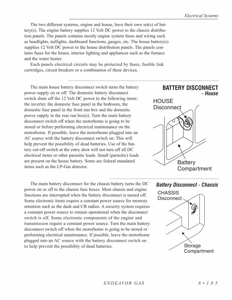
The two different systems, engine and house, have their own set(s) of bat-tery(s). The engine battery supplies 12 Volt DC power to the chassis distribu-tion panels. The panels contains mostly engine system fuses and wiring suchas headlights, taillights, dashboard functions, gauges, etc. The house battery(s)supplies 12 Volt DC power to the house distribution panels. The panels con-tains fuses for the house, interior lighting and appliances such as the furnaceand the water heater.
Each panels electrical circuits may be protected by fuses, fusible linkcartridges, circuit breakers or a combination of these devices.
The main house battery disconnect switch turns the batterypower supply on or off. The domestic battery disconnectswitch shuts off the 12 Volt DC power to the following items:the inverter, the domestic fuse panel in the bedroom, thedomestic fuse panel in the front run box and the domesticpower supply in the rear run box(s). Turn the main batterydisconnect switch off when the motorhome is going to bestored or before performing electrical maintenance on themotorhome. If possible, leave the motorhome plugged into anAC source with the battery disconnect switch on. This willhelp prevent the possibility of dead batteries. Use of the bat-tery cut-off switch at the entry door will not turn off all DCelectrical items or other parasitic loads. Small (parasitic) loadsare present on the house battery. Some are federal mandateditems such as the LP-Gas detector.
The main battery disconnect for the chassis battery turns the DCpower on or off to the chassis fuse boxes. Most chassis and enginefunctions are interrupted when the battery disconnect is turned off.Some electronic items require a constant power source for memoryretention such as the dash and CB radios. A security system requiresa constant power source to remain operational when the disconnectswitch is off. Some electronic components of the engine andtransmission require a constant power source. Turn the main batterydisconnect switch off when the motorhome is going to be stored orperforming electrical maintenance. If possible, leave the motorhomeplugged into an AC source with the battery disconnect switch onto help prevent the possibility of dead batteries.
Electrical Systems------------------------------------------------------------------------------------------------------------------------------------------------------------------------------------------------------------------------------------------------------------------------------------------------------------------
E N D E AVO R G A S 8 • 1 8 5
BATTERY DISCONNECT- House
Battery Disconnect - Chassis

Electrical Systems---------------------------------------------------------------------------------------------------------------------------------------------------------------------------------------------------------------------------------------------------------------------------------------------------------------------
E N D E AVO R G A S8 • 1 8 6
NOTE: If an AC source is not available and the motorhomeis not going to be used or is stored more than 48 hours it isrecommended to turn the battery disconnect switch off.
If shore power service is available all that is necessary is to connect themotorhome to the shore power service using the supplied shore power cord.The cord is located in the compartment on the driver’s side of the motorhome.After connecting the unit to shore power wait approximately one minute for theinverter to “stabilize” charging of the batteries before starting air conditionersor other large AC loads. In many instances 50 Amp shore service is not available.Proper electrical adapters must be used to connect the supplied shore powercord to the shore service available. When connecting to anything other than 50Amp shore service use caution not to overload the supplied shore service breaker.Appliances and outlet loads will have to be operated in sequence rather than allat the same time.
NOTE: Below are the three types of shore power outletsmost commonly used.
Depending on the motorhome AC Distribution panel configuration theremay be 20 Amps, 30 Amps or 50 Amps with the energy management system.
CAUTION: Avoid the risk of electrical shock or componentdamage by disconnecting from shore power during electricalstorm activity. Use the inverter or start the generator if ACpower is needed.
The transfer switch automatically transfers power from the shore cordthrough the transfer switch and to the 110 Volt AC breaker panel. When thegenerator is used the transfer switch has a time delay built into it. This allowsthe generator time to warm up before an AC load is applied to it. The transferswitch will automatically select the generator over shore power even thoughshore power is hooked up.
SHORE POWERHOOK-UP
Transfer Switch

NOTE: To prevent damage to the transfer switchdo not have appliances on or AC loads plugged intooutlets when hooking up to shore power or startinggenerator. The transfer switch will begin to disen-gage between 85-90 Volts AC. Operation at thisvoltage may damage transfer switch, appliances orother items plugged into outlets.
WARNING: Keep fingers away from metal con-tacts of shore plug end. Avoid standing water.Serious electrical shock and personal injury canoccur. To avoid the risk of an electrical shock turnthe circuit breaker off for the shore power outlet beforemaking shore power connection.
The 120 Volt AC gasoline generator is located in a service compartment on theroadside of the motorhome. The generator may stop running before the chassisfuel tank is completely empty. This is a safety feature to prevent the motor-home from running completely out of fuel.
A preheater control lever on the generator needs to be set for the appropriatetemperature to prevent the engine from erratic operation and over-speeding. Attemperatures below 40° F (4° C), move the lever to the WINTER position.Between 40° F (4° C) and 70° F (21° C) the lever can be in either theSUMMER or WINTER position. Above 70° F (21° C) move the lever to theSUMMER position.
Starting the Generator:The generator is controlled by either a remote switch on the dash or a
switch located on the generator. To start the generator shut off all 120 Volts ACappliances and equipment. Push the start switch and hold until the generator isrunning, then release the switch. The dash switch is lit when the generator isrunning. Normally the generator will start running within five seconds. If itfails to start after cranking for 10 seconds release the switch and wait 30 secondsbefore cranking again. If the generator fails to start after five attempts allowthe starter motor to cool down for five minutes before cranking again.
Stopping the Generator:Turn off all 120 Volt AC appliances and equipment and run the generator
for at least three minutes before turning it off. This allows lubricating oil tocarry heat away from the combustion chamber and the bearings. To stop thegenerator push the switch to the stop position for approximately one secondand then release it.
Electrical Systems------------------------------------------------------------------------------------------------------------------------------------------------------------------------------------------------------------------------------------------------------------------------------------------------------------------
E N D E AVO R G A S 8 • 1 8 7
GENERATOR - 120 AC

For in-depth information regarding low oil shut-down pro-tection, circuit breaker locations and maintenance proce-dures refer to the manufacturer’s brochure in the Owner’sinformation file.
The 12 Volt house contains fuses (located in the bedroom cabinet) that pro-tect the electrical circuits. These fuses are the standard automotive type. When afuse is “blown,” the wire in middle of the plastic case will be burnt. A broken,bad or “blown” fuse must be replaced with a fuse of the same rating and type.Use of a fuse with a different rating or type will defeat the circuit protectionprovided by that fuse and could result in damage o the motorhome’s electricalsystem.
Fuse assignments are as followed:
1. Bath Lights/Vents - 15 Amp Fuse2. Dinette/Porch/Rt. Overhead - 15 Amp Fuse3. Bedroom/ODS Lights - 15 Amp Fuse4. Kitchen/Left Overhead, Stove Vent
(Opt Vent - 15 Amp Fuse)5. Ceiling Lights - 15 Amp Fuse6. Furnace - 15 Amp Fuse7. Monitor Panel - 15 Amp Fuse8. Slide-out - 15 Amp Fuse 9. Radio - 5 Amp Fuse
Circuit Breaker assignments are as follows:
Left Side Right Side• 50 AMP MAIN • Converter, Bedroom TV, Dining• Front Air Conditioner Room• Rear Air Conditioner • Bathroom, Kitchen, Refrigerator,
TV, VCR• Water Heater• Microwave
Electrical Systems---------------------------------------------------------------------------------------------------------------------------------------------------------------------------------------------------------------------------------------------------------------------------------------------------------------------
E N D E AVO R G A S8 • 1 8 8
30 AMPS FUSES &CIRCUITSDistribution Panel-Inside

The AC distribution panel is located in the bedroom. The main ACpanel 120 Volt circuit breakers receive power from the transfer switch,which is powered by either shore power or the on board generator.Power is introduced into the panel to the 50 Amp MAIN breaker first,followed by power being fed into the individual branch circuit break-ers. The panel label describes the breaker layout and the item, outlet or appli-ance to which they pertain.
WARNING: This panel contains high voltage which cancause serious injury or death. Before beginning any work ortesting procedures involving the electric panels, or any of thebranch circuits, be sure the motorhome is unplugged fromshore power, the generator is not running and the inverter isin the OFF position. Certain testing procedures can require the AC power to beon. Only qualified personnel or personnel with electricalbackgrounds should attempt any testing procedures.
Branch circuit breakers supply AC power to the different items or “loads.”An electrical load is any item or device that will use current when suppliedwith an electromotive force. Should a breaker “trip” from over current use, ora short circuit condition, the load to which the breaker is supplying the electro-motive force should be reviewed or disconnected to determine the cause of thetrip. If no cause is found, or not readily apparent, reset the breaker by togglingthe breaker to the OFF position, then back to ON. Should the breaker tripagain after the load is reapplied it may indicate a fault with that particular load.Do not continue to reset breaker until the problem has been diagnosed andcorrected.
Breaker current ratings are current set points in which the breaker isdesigned to operate. The internal configuration of the circuit breaker isdesigned to trip when excess current is drawn through the breaker.The tripaction of the circuit breaker can occur within milliseconds due to the speed at
Electrical Systems------------------------------------------------------------------------------------------------------------------------------------------------------------------------------------------------------------------------------------------------------------------------------------------------------------------
E N D E AVO R G A S 8 • 1 8 9
50 AMP DISTRIBUTIONPANEL (OPTIONAL)
House 110 AC Panel
ENCLOSED ENERGY MANAGEMENT EQUIPMENT

which electricity can travel. Breaker ratings are set to operate on a continuousload at 80% of the breaker’s rated capacity. For example: A breaker with a 20Amp rating will handle a continuous load of 16 Amps. This designed set pointis when an inductive load is applied, such as when an electric motor turns on.As the motor starts to spin, current consumption may momentarily exceed therated capacity of the breaker. As the electric motor comes up to operating speedthe electric motor’s current consumption will fall. The AC current load thenfalls back into the breaker’s rated 80% set point. This electric principle shouldbe kept in mind when using anything other than 50 Amp shore service andusing appliances with electric motors. When using outlets care should be con-sidered when applying loads such as electric motors, heaters, coffee makers,toasters, hair dryer or other large current consuming loads. If the current ratingof a load is not known it is usually stated on most electrical items. The ratingwill either be in amps or watts. Current ratings stated on electrical items willchange slightly with voltage fluctuations. As voltage increases current con-sumption decreases. As voltage decreases current consumption increases. Thismay explain why in some instances items operated at borderline voltage to cur-rent tolerances may seem fine in one location but problematic in another.
NOTE: To calculate watts to amps simply divide the watt fig-ure by the voltage of which the item operates from. Forexample: The electrical item is rated at 1,370 watts. Dividethat by the operating voltage of 115 volts which equals 11.913amps. Use this formula to calculate load to current supplyratio.
The Energy Management System is easily identified by the remote displaypanel located inside motorhome above the entrance door.
The 50 Amp Smart EMS consists of two elements: the display panel and thebedroom distribution panel. The display panel is mounted in the inside over-head compartment next to the entrance door. The distribution panel located inthe bedroom is a completely self-contained 120/240 Volt power distribution andenergy management system intended to be used in recreational vehicles. It ishoused in a sheet metal enclosure with removable front panel. It provides cir-cuit protection for all the 120 Volt AC loads in the motorhome and a system ofenergy management to minimize the over-loading and tripping of circuit break-ers.
Circuit Breakers: The distribution panel offers slots for eight single ordual standard 120 Volt circuit breakers. Two of these breakers, located in thetwo center stab positions, must be a 50 Amp unit that act as a main input pro-tection for each of the lines supplying the remainder of the branch breakers (upto 12).
Electrical Systems---------------------------------------------------------------------------------------------------------------------------------------------------------------------------------------------------------------------------------------------------------------------------------------------------------------------
E N D E AVO R G A S8 • 1 9 0
50 AMP ENERGYMANAGEMENTSYSTEM -(OPTIONAL)

Energy Management: The 50 Amp Smart EMS automatically senses theavailable power to the motorhome. It determines whether it is connected to a120 Volt AC - 30 Amp shore power source, 50 Amp shore power source orgenerator source. Depending upon available power, it controls the operation of6 possible loads as indicated on distribution panel. These may be any typeload, but are typically heavier loads; those whose use can be “postponed untila time when current is available for their use. If the available power source is120 Volt AC - 30 Amp shore power it attempts to keep the total 120 Volt cur-rent draw to less than 30 Amps.
Operation: If 120 Volt AC is not available at the distribution panel, L1 orL2 outputs, the system shuts itself off. This feature is intended to prevent thesystem from drawing current from the +12 VDC battery supply when not inoperation.
When 120 Volt AC power is applied the system automatically powers upand determines the nature of the power source.
If the generator is running, 120 Volt AC will be present at the distributionpanel L1 and L2 inputs. In this mode the energy management feature is dis-abled and all control relay contacts are closed, energizing all of the controlledloads. The control Module sends a signal to the display panel causing the loadmeter to display actual load current, the GEN SET service indicator to lightand all power status indicators to light.
If 120 Volt AC is present at the distribution panel L1 and L2 inputs the sys-tem will assume that 120 Volt AC, 30 Amp shore power is available and theenergy management feature will be enabled. If only 20 Amp service is avail-able the user must select the 20 AMP service mode by momentarily press-ing the 20/30 Amp select switch on the Control Panel. Initially all relay con-tacts are closed and the total current is monitored. If the total current shouldexceed the service limit the system will turn off the first load in the sheddingtable. As it turns the loads off it calculates the amount of current that wasremoved, which is the value for that load. This value is placed in memory. Ifthe current remains above the service limit the system will turn off the nextload in shedding table. Again it calculates the amount of current that wasremoved and places this value, which is the value of that load, in memory. Thesystem continues to turn off loads until the total current falls below the servicelimit or all of the six controlled loads have been shed. Through this process thesystem has “learned” the amount of current that each particular load draws.This feature compensates for the differences in current draw over a range ofline voltage and ambient temperature by re-learning the load each time it isturned off or “shed.”
The 50 Amp Smart EMS will now wait until the total current is lower thanthe service limit and enough current is available (as compared with the amountin memory for the last load shed) before it will turn that load back on. Thisassures that there is sufficient current to operate the load.
Electrical Systems------------------------------------------------------------------------------------------------------------------------------------------------------------------------------------------------------------------------------------------------------------------------------------------------------------------
E N D E AVO R G A S 8 • 1 9 1

NOTE: There is a two minute minimum delay period after aload is shed before the load will be turned on again to pre-vent air conditioners from turning on with a head pressure.
Three Hour Averaging: The RVIA (Recreational Vehicle IndustryAssociation) in conjunction with the NEC (National Electrical Council) haveestablished rules regarding the rating of electrical systems and the use of energymanagement systems. One of these rules requires that if any energy manage-ment system is used the average total load current for the system over a 3 hourperiod be limited to 80% of the service rating. For that reason the 50 Amp EMScalculates the average running current for the system and, if it exceeds 80% ofthe service rating, the EMS sheds loads to reduce the average current below thatlimit.
For example, if a system operating under 120 Volt AC, 30 Amp service hasbeen running at the 30 Amp limit for three hours the EMS will change its shed-ding threshold to 24 Amps and turn off loads until the 24 Amp limit is attained.If the user selects the 20 Amp service mode this limit will translate to 16 Amps.Because the EMS calculates a running 3 hour average, if the average load cur-rent drops below the limit the system will restore power to loads based on theirimpact on the limit. If the system is in the averaging mode the decimal point atthe lower right corner of the load meter display on the display panel will illumi-nate.
Display Panel: The display panel is located in the inside overhead com-partment next to the entrance door and connects to the distribution panel locat-ed in the bedroom. Six power status LED’s indicate power is applied to thoseloads. These LED’s are on when the power is applied. The load meter has a twodigit display to indicate the amount of current actually being drawn by all theappliances in the motorhome.
Four service type LED’s indicate the source for 120/240 Volt AC power.Three of these sources are automatically detected and indicated by the EMS,namely: Gen Set Service, 50 Amp Service and 30 Amp Service.
The 20 Amp service mode is not automatically detected and the opera-tor must manually select the 20 Amp mode when 20 Amp service is avail-able. The service select button allows the current threshold to be set to either 30Amps or 20 Amps to match the incoming service.
Electrical Systems---------------------------------------------------------------------------------------------------------------------------------------------------------------------------------------------------------------------------------------------------------------------------------------------------------------------
E N D E AVO R G A S8 • 1 9 2

The 12 Volt house contain fuses (located in the bedroom overheadcabinet) that protect the electrical circuits. These fuses are the standardautomotive type. When a fuse is “blown,” the wire in middle of the plas-tic case will be burnt. A broken, bad or “blown” fuse must be replacedwith a fuse of the same rating and type. Use of a fuse with a different rating ortype will defeat the circuit protection provided by that fuse and could result indamage to the motorhome’s electrical system.
The distribution panel (12 Volt DC) is located inside the front roadsidecompartment. Fuse assignments are listed on a fuse label attached to the insidecover of the front distribution panel. When replacing fuses always replace withthe same size as listed for a particular location. Fuse sizes shown are maxi-mum fuse size allowable. Installing fuse sizes other than those listed can causeelectrical wiring to become overloaded and create hazardous situations.
Fuse assignment are as followed:1. Slide-out Room - 15 Amp circuit breaker2. LP Detector/CO Detector - 3 Amp Fuse3. Power Seat (Opt) - 15 Amp circuit breaker4. Power Seat (opt) - 15 Amp circuit breaker5. Storage Lights - 15 Amp Fuse6. Bedroom Slide-out - 15 Amp circuit breaker7. Auxiliary Start/TV Amp - 7.5 Amp Fuse8. Cigarette Lighter - 15 Amp Fuse9. Map Lights - 7.5 Amp Fuse10. C.B. Radio - 2 Amp Fuse11. Service Light - 7.5 Amp Fuse12. 12V Receptacle - 15 Amp Fuse13. Step Switch - 7.5 Amp Fuse14. Step Motor - 25 Amp Fuse
Electrical Systems------------------------------------------------------------------------------------------------------------------------------------------------------------------------------------------------------------------------------------------------------------------------------------------------------------------
E N D E AVO R G A S 8 • 1 9 3
50 AMP DISTRIBUTIONPANEL (OPTIONAL)
HOUSE 12 VOLT
#-COLOR-AMP CIRCUIT1 - BLUE - 15 BATH LTS/VENT2 - YELLOW - 15 DIN,PRCH,R O/H3 - GREEN - 15 BEDROOM LTS4 - VIOLET - 15 VENTS, L 0/H5 - RED - 15 CEILING LTS6 - GRAY - 15 FURNACE,A/C 12V7 - RED/T - 15 MONITOR PANEL8 - BLACK - 15 SLIDE-OUT9 - GRAY - 5 RADIO10 - RED - 15 ELECTRIC AWNING11 - RED - 15 COMPUTER TABLE
12 Volt Distribution Panel
- Outside

20. Rear Vision (Opt) - 5 Amp Fuse21. Leveling Jacks (Opt) - 5 Amp Fuse22. Accessory Switch - 15 Amp Fuse25. Air Conditioner - 20 Amp Fuse26. Jack/Antenna Warning Lamp - 5 Amp Fuse27. TV Cutout Relay - 7.5 Amp Fuse28. Galley Slide-Out Room Ign. Relay - 7.5 Amp Fuse29. Mirror Heaters - 15 Amp Fuse30. Mirror Motors - 1 Amp Fuse33. Step/Isolator Relay - 7.5 Amp Fuse34. Marker Lights - 7.5 Amp Fuse
NOTE: Number’s 15, 16, 17, 18, 19, 23, 24, 31, 32 arereserved for future use.
The chassis fuse boxes are placed in two locations. One panel is locatedinside the motorhome under the dash panel. The box located under the dash isreferred to as the Central Junction Box.
The other panel is located outside, mounted on the front firewall. This box isreferred to as the Power Distribution or the Battery Junction Box.
Electrical Systems---------------------------------------------------------------------------------------------------------------------------------------------------------------------------------------------------------------------------------------------------------------------------------------------------------------------
E N D E AVO R G A S8 • 1 9 4
Chassis 12 VoltDistribution Panel -Front
Fuse Position AMPS Circuits Protected
1 20
Right Turn Signal Relay Coil, Left Turn Signal Relay Coil, Right Turn Indicator, Body Builder Right Rear Turn/Stop Feed, Body Builder Turn/Stop Feed.
2 - NOT USED3 - NOT USED4 15 Interior Lamp Relay5 10 Accessory Feed #16 10 Trailer LH Turn/Stop Lamp7 15 Blower Motor Relay8 - NOT USED
9 20Trailer Tow Electrical Brake Controller Feed, Body Builder Right Rear Turn/Stop Feed, Body Builder Left Rear Turn/Steop Feed, Body Builder Stoplamp Feed
10 5 Instrument Cluster, Hydromax Lamp
11 30 Windshield Wiper/Washer Module, Wiper Feed
12 10 Trailer Tow Right Stop/Turn Feed13 10 4 WABS Module
14 10Instrument Cluster, Hydro-Max Monitor, Warning Chime Module, Transmission Control Switch
15 15 LH Turn Relay16 20 Body Builder Battery Feed17 5 Body Builder Radio Feed18 - NOT USED19 5 DRL On/Off Relay20 - NOT USED21 15 RH Turn Relay
Fuse Position AMPS Circuits Protected
22 - NOT USED23 - NOT USED24 - NOT USED25 10 Body Builder Right Headlamp (Low Beam)26 10 Shift Lock Acutator, Speed Control Servo27 - NOT USED28 - NOT USED29 - NOT USED30 - NOT USED31 10 Body Builder Left Hadlamp (Low Beam)
32 10Digital Transmission Range (DTR) Sensor (Reversing Lamp Feed)
33 - NOT USED34 - NOT USED
35 20 Headlamp High Beam, High Beam Indicator36 - NOT USED37 - NOT USED38 10 Body Builder Accessory Feed #2 (Run)39 - NOT USED40 - NOT USED
41 10
Headlamp switch, Dimmable Light, Body Builder Feed, Instrument Cluster Illumination
42 - NOT USED43 - NOT USED44 - NOT USED
Central Junction Box:
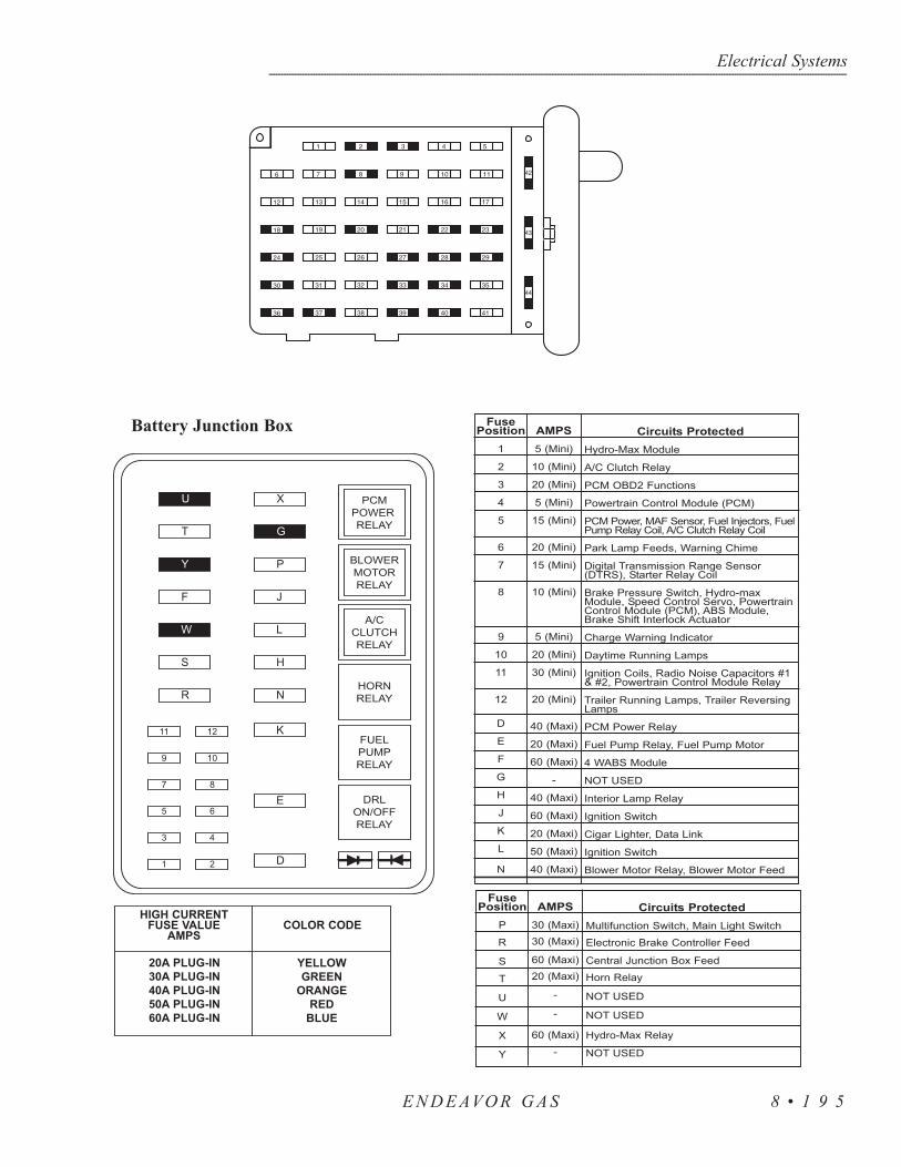
Electrical Systems------------------------------------------------------------------------------------------------------------------------------------------------------------------------------------------------------------------------------------------------------------------------------------------------------------------
E N D E AVO R G A S 8 • 1 9 5
Battery Junction Box

Breaker current ratings are current set points in which the breaker isdesigned to operate. The internal configuration of the circuit breaker is designedto trip when excess current is drawn through the breaker. The breaker will heatup from the excess current causing the breaker to trip. The trip action of the cir-cuit breaker can occur within milliseconds due to the speed at which electricitycan travel. Breaker ratings are set to operate on a continuous load at 80% of thebreaker’s rated capacity. For example: A breaker with a 20 Amp rating will han-dle a continuous load of 16 Amps. This designed set point is when an inductiveload is applied, such as when an electric motor turns on. As the motor starts tospin current consumption may momentarily exceed the rated capacity of thebreaker. As the electric motor comes up to operating speed the electric motor’scurrent consumption will fall. The AC current load then falls back into thebreaker’s rated 80% set point. This electric principle should be kept in mindwhen using anything other than 50 Amp shore service and using applianceswith electric motors. When using outlets care should be considered when apply-ing loads such as electric motors, heaters, coffee makers, toasters, hair dryer orother large current consuming loads. If the current rating of a load is not knownit is usually stated on most electrical items. The rating will either be in Amps orwatts. Current ratings stated on electrical items will change slightly with volt-age fluctuations. As voltage increases current consumption decreases. As volt-age decreases current consumption increases. This may explain why in someinstances items operated at borderline voltage to current tolerances may seemfine in one location but problematic in another.
NOTE: To calculate watts to amps simply divide the watt fig-ure by the voltage of which the item operates from. Forexample: The electrical item is rated at 1,370 watts. Dividethat by the operating voltage of 115 volts which equals 11.913amps. Use this formula to calculate load to current supplyratio.
Electrical Systems---------------------------------------------------------------------------------------------------------------------------------------------------------------------------------------------------------------------------------------------------------------------------------------------------------------------
E N D E AVO R G A S8 • 1 9 6
Circuit Breakers

The 12 Volt fuses, located in this distribution panel, service theinterior house lighting, ventilation fans, monitor panel, furnace andwater heater. Should a fuse blow it will be evident by the brokenmetal strip located in the center of the fuse. Replacement fusesshould be of the same amperage. If a higher rated fuse is installed itcan damage the wiring. Fuse current set points follow much of thesame electrical principle as the 120 Volt AC breakers. Using 12Volt DC as the electromotive force can make it more susceptible tooutside influences, such as corrosion from weathering or oxidation.
The large variety of applications this voltage can be used inmakes it a diet staple for most of the recreational vehicle and auto-motive industries. The danger from shocks with this voltage is min-imized but can still occur. A good example is when a magneticfield is generated, then collapses when the power supply is cut.The result is a discharge that can reach tens of thousands of voltsfor a short time period. Care should be used when working withthis voltage as current values can be quite high, like in the case ofa battery cables.
Shorting a battery cable to ground with a battery at a reasonablestate of charge can result in a fire or serious personal injury from aburn.
One of the most widely used tools used for testing a 12 Volt problem is thetest light. Test lights come in a host of varieties such as a light bulb with aprobe and ground clip to the more elaborate electronic ones that measure awide scale of voltages and perform a variety of functions. A VOM or VoltOhm Meter is used to perform a multitude of tests. It is generally used whenexact values are needed for evaluation. These meters come in an analog or dig-ital format. Either of these two testing tools may be used, depending upon per-sonal preference. If a 12 Volt light is not working the test light may be bettersuited for this. In the case of a charging system problem the meter may be thetool of choice. In any situation the testing tool is an invaluable piece of equip-ment when it comes to determining an electrical problem.
Should it become necessary to use testing tools take certain precautions andconsider three things. First, recognize when the problem is beyond your skilllevel. Nothing will create more mayhem than being armed with tools andgoing in an unknown direction. Good intentions have led to major problems. Thesecond item to keep in mind is if something will cause more grief by beingdealt with now than if it were left alone and repaired by a professional at amore convenient time. How many times have you said to yourself, “This will
Electrical Systems------------------------------------------------------------------------------------------------------------------------------------------------------------------------------------------------------------------------------------------------------------------------------------------------------------------
E N D E AVO R G A S 8 • 1 9 7
Tools of the Trade
Fuses
AMPERAGE COLOR1 BLACK2 GRAY3 VIOLET4 PINK5 GOLD
7.5 BROWN10 RED15 BLUE20 YELLOW25 CLEAR30 GREEN
Knowing When toSay No
only take a few minutes,” only to find it is taking an entire day and you wishedyou had not touched it? The third item to consider is whether or not the currentsituation may be potentially dangerous if left to be repaired at a more conven-ient time?
NOTE: Check all related fuses before assuming you haveencountered an electrical problem or situation. Spare fusesshould be kept on hand and can be purchased from an autoparts stores. A fuse description label is on the distributionpanel cover.
WARNING: If a fuse blows replace the fuse with sameamperage rating and type. Installing higher amperage fusescan damage the wiring or the item the fuse is protecting, ormay cause a fire. If the fuse repeatedly blows after replacingit do not continue to replace it. Have the problem diagnosedand corrected by a qualified technician.
The operation of the battery is based on a chemical reaction. The battery iscomprised of lead plates and a solution of distilled water and sulfuric acid. Thesolution, when mixed together, is known as “electrolyte.” The 12 Volt battery isactually six batteries in one case. When charged, each cell has a voltage of 2.1Volts. When six cells are hooked together this makes a 12.6 Volt battery (fullycharged).
Electrons are stored on the negative plates. When a load (eg. a light bulb) isput between the positive and negative terminals the electrons move from thenegative plate to the positive plate through the “load” and then back to theground terminal. At this time the sulfuric acid leaves the water and adheres onto the plates of the battery. The electrolyte solution keeps the electrons fromflowing while the battery is in the “at rest” position.
Charging the battery moves the sulfuric acid back into solution with the distilled water. A battery left in a low or discharged state will cause the acid to “sulfate.” In attempting to recharge the battery the acid has become hardenedand no longer will leave the plates and enter into the liquid solution with thedistilled water. The lowered acid to water ratio has a direct affect on the battery’sability to release the stored electrons (power output) and the length of time itcan perform (reserve capacity). Batteries left in a discharged condition willreadily freeze. This can crack the case allowing the solution to spill, it can alsowarp the plates.The acid acts like an “antifreeze” for the battery. This is whybatteries should not be left or stored in a “discharged” condition.
Batteries come in different sizes, types, amp hours, voltages and chemistries.There are nearly as many descriptions of battery types and how they should beused as there are people willing to offer advice on them. Although it is not possi-
Electrical Systems---------------------------------------------------------------------------------------------------------------------------------------------------------------------------------------------------------------------------------------------------------------------------------------------------------------------
E N D E AVO R G A S8 • 1 9 8
BATTERY - HOW IT WORKS
Battery Types

ble to cover batteries in their entirety there are guidelines that can be followed toensure that the batteries are well maintained.
The starting battery is designed for high output cranking power, but not fordeep cycling like the house batteries are designed to do. The starting batterywill not last long in a deep cycle application. The way it is rated should give agood indication of its intended use. “Cold Cranking Ampere” is a measurementof amperage output that can be sustained for 30 seconds. The starting batteryuses thin plates to maximize the surface area of the battery. This allows a veryhigh starting current, but lets the plates warp when the battery is deep cycled(discharged).
This is the type of battery that is best suited for use with 12 Volt operatedlights, appliances and inverters. Deep cycle batteries are designed to have themajority of their capacity used before being recharged. Available in many sizesand types, the most common is a non-sealed, liquid electrolyte battery. Thenon-sealed types have battery caps. The caps should be removed periodicallyto check the level of electrolyte. When a cell is low only distilled water shouldbe added. Water consumption will vary depending on many factors: how farthe batteries are depleted, how much voltage, how long the voltage is beingapplied to charge the batteries and how often this occurs.
NOTE: Tap water contains minerals which can alter batterychemistry and ruin the battery. Use only distilled waterwhen refilling the battery.
At a minimum, the battery electrolyte level should be checked at least oncea month. Check the level sooner if the battery is frequently used. The levelshould be above the top of the plates, but not overfull. Most batteries have aplastic cup or well. The electrolyte level should be approximately 1/8” belowthe well to allow room for expansion while the battery is being charged. Over-filling the battery will allow the electrolyte solution to boil or gas out of thebattery cap. Remember to use only distilled water to refill the battery. A bat-tery with a low electrolyte level will boil the water out rapidly once the plateshave been exposed to air. This process may take only a matter of hours. If thishas happened the battery is more than likely damaged.
After checking the battery’s electrolyte levels it is also a good idea to checkthe battery connections for tightness and corrosion. If any corrosion is founddisconnect the cables (make sure to mark their locations) and carefully cleanthem with a mild solution of baking soda and water. There are also aerosolproducts available that will work. This will neutralize any acid that may bepresent. Do not allow the solution to enter the battery as this will damage the
Electrical Systems------------------------------------------------------------------------------------------------------------------------------------------------------------------------------------------------------------------------------------------------------------------------------------------------------------------
E N D E AVO R G A S 8 • 1 9 9
Starting Battery
Deep Cycle Battery
Battery Maintenance

electrolyte balance. Use water to rinse the top of the battery area when done.Hook the cables back to the battery. Coat the terminals with petroleum jelly oran anti-corrosive grease.
The battery cable to battery terminal connections should be metal to metal.Periodically check the batteries for corrosion. Look for cracks and check thevent plugs. Replace them if they are cracked or missing. Keep the top of thebatteries clean. The accumulation of electrolyte and dirt may permit smallamounts of current to flow between the terminals which can drain the battery.
WARNING: Liquid lead acid batteries produce hydrogen gaswhile being charged. This is highly explosive. Do not smokearound batteries. Extinguish all flames in the area. Batteriesmay explode resulting in fire, personal injury, propertydamage or death.
There are several ways in which a battery can be tested and monitored. Themotorhome uses a monitor panel which shows the status of the house batteriesat a quick glance. Pressing and holding the test button, the power level will bedisplayed on the battery scale. The illustration shown explains in more detailthe scale and indications.
A more efficient way of testing the batteries is to check the electrolyte solution.The only way to test a battery’s electrolyte solution is with a hydrometer. Manystyles are available, from types with cylinder graduation (shown here) to typeswith floating balls. Hydrometers can be purchased from most auto parts stores.The hydrometer tests the battery’s electrolyte solution which is measured in spe-cific gravity (sulfuric acid to water ratio). Distilled water has a specificassigned gravity of 1,000. The hydrometer is calibrated to this mark. Pure sulfuricacid has a specific gravity reading of 1,840. The acid is 1.84 times heavier thanwater. The electrolyte solution is about 64% water to 36% acid (fully chargedbattery). Hydrometers with cylinder graduation are graphed and the exact state
Electrical Systems---------------------------------------------------------------------------------------------------------------------------------------------------------------------------------------------------------------------------------------------------------------------------------------------------------------------
E N D E AVO R G A S8 • 2 0 0
Testing the Batteries

of specific gravity can be determined. Temperature and recent battery activity (charging or discharging) affect the
hydrometer readings. It is best to check the battery when it has been “at rest”for at least three hours, although readings taken at other times will give a “ballpark” figure. Using the hydrometer, draw the electrolyte solution up into thetube. Allow the hydrometer to attain the same temperature as the electrolytesolution. Note the reading for that cell. Complete the same test for the rest ofthe cells on that battery bank.
Chart readings are taken at 80° Fahrenheit. Temperature affects thehydrometer readings. The higher the electrolyte temperature, the higher thespecific gravity reading. The lower the temperature, the lower the specificgravity reading will be. Add or subtract four points for each 10° variance fromthe 80° Fahrenheit chart. Readings between cells should not vary more than 50points.
If one cell in a particular battery bank being tested is at a 50% state ofcharge while the others are fully charged, charge that battery to see if the lowcell will come up. At the same time, do not over charge the “healthy” cells.
If the low cell does not come up after charging, this battery can damage therest of the battery bank and should be replaced. An accurate digital volt meter+ - .5% will also give an indicator of the battery’s state of charge.
Another test that can be performed is to put the battery(s) under a specified load for a predetermined length of time for that particular battery’s rating. This machine is usually an adjustable carbon pile that can varythe load applied to the battery(s) while monitoring voltage to see if they willperform to the specific rated capacities.
NOTE: See chart for temperature compensation. Liquid lev-els should be even between the cells of the battery being test-ed as it will affect the accuracy of the test.
WARNING: Sulfuric acid in the batteries can cause severeinjury or death. Sulfuric acid can cause permanent damageto eyes, burn skin and eat holes in clothing. Always wearsplash-proof safety goggles when working around the bat-tery. If battery electrolyte is splashed in eyes or on skinimmediately flush the affected area for 15 minutes withlarge quantities of clean water. In case of eye contact seekimmediate medical aid. Never add acid to a battery once thebattery has been placed in service. Doing so may result inhazardous splattering of electrolyte.
Electrical Systems------------------------------------------------------------------------------------------------------------------------------------------------------------------------------------------------------------------------------------------------------------------------------------------------------------------
E N D E AVO R G A S 8 • 2 0 1

1. Physical Condition:Active material flakes off the plates and fall to the bottom of the cell. This
is normal, but sediment accumulates under the plates and can short out a cell.The plate separators fail to insulate positive and negative plates in a cell and thecell becomes shorted, ruining the battery.
2. Insufficient Electrolyte:This allows exposed portions of the plates to sulfate rapidly. This reduces
the battery’s ability to accept a charge and the battery capacity is reduced.Accelerated erosion of the lower portions of the plates occur from higher thannormal acid content due to water loss. Only the water evaporates, not the acid.The battery also has a higher internal resistance when low on water. Add onlydistilled water. Fill each cell to the bottom of the vent well when the battery iswarm. Filling a very cold battery with water to the bottom of the vent well willcause overspill when the battery warms up and the plates expand. A BatteryFormula For Failure: The battery has a higher internal resistance when low onwater, therefore: high resistance = more heat = shorter battery life!
3. Sulfation:When a battery is allowed to remain discharged too long the accumulated
lead sulfate in the plate material solidifies and cannot reenter the electrolyte.Sulfate in plates is not able to reconstitute the electrolyte to a higher specificgravity, or to restore the plate material to a more active composition.
4. Overheating:A battery operated, when the electrolyte temperature reaches 125º F,
increases the chemical reaction. This increases the corrosion of the plates andreduces the battery life. When overheated the battery plates tend to buckle anddestroy the structural integrity of the battery.
5. Freezing:When the electrolyte freezes, ice formed dislodges the active material
from the plates. The battery case may crack and the electrolyte will leak outwhen thawed. It is especially important to keep a battery at full charge in coldweather to prevent freezing. The high specific gravity of a fully charged batterydoes not freeze as easily. Never attempt to recharge a frozen battery. Warm it upfirst.
6. Corrosion:Corrosion from spilled or splashed electrolyte form deposits that can
conduct electricity and cause battery drain. Clean off all corrosion, especiallyaround the battery terminals and on the top cover of the battery. Prevent accumulation by coating the terminals and the exposed metal cable connectorswith high temperature grease.
Electrical Systems---------------------------------------------------------------------------------------------------------------------------------------------------------------------------------------------------------------------------------------------------------------------------------------------------------------------
E N D E AVO R G A S8 • 2 0 2
Seven Reasons WhyBatteries Fail
7. Overcharging:Overcharging rapidly converts water to gas and decreases the elec-
trolyte’s water content as the water evaporates. The electrolyte level drops andbecomes more acid in content. This subjects the plates to a higher concentra-tion of sulfuric acid and results in early battery failure.
NOTE: Any time you add more than one or two ounces per-cell per-thousand miles driven, check the motorhome charg-ing system for overcharging. Prolonged overcharging gener-ates excessive heat inside the battery, which buckles theplates and destroys the battery. It is a fact that over 50% ofbattery failures are caused by overcharging.
Why does the voltage on a discharged battery measure the same as a fullycharged battery until the loads are applied? The simple answer to this might goas follows: A battery creates electrical power by converting energy from achemical reaction into electrical energy. As this reaction slows down the bat-tery voltage will drop. In a lead acid battery the electrolyte conductivity (howwell electrical current can flow through it) changes. The same current may be available but the rate of the reaction decreases, causing a voltage drop.
Another way of looking at this is to use the analogy of a water pump (a battery is an electric pump). The pressure in psi (pounds per square inch)that a pump delivers is like a battery’s voltage. The volume of water in GPM (gallons per minute) is like the electrical current. Let’s look at a 12 psi pumpwith no loads (the pump is running but the outflow valve is turned off). Thepump will run and the internal pressure of the pump will build up to somepoint higher than 12 psi. Once the valve is opened and the water is free to flowinto the loads the pressure will drop to the rated output pressure of 12 psi, butonly if the load is not too big. If the pump is designed to maintain 12 psi at 15GPM, and a load demanding 20 GPM is connected, the pump will not be ableto keep up and the pressure will get sucked down to a lower psi.
If the load is then reduced or removed the pump will catch up andreturn to its rated 12 psi pressure. If the pump has an infinite source of water,such as a lake or the water utility (this is like the grid, no battery), the pumpwill never run out of pressure. If the pump never runs out of pressure and isoperated at or below it’s 15 GPM level, it will hold 12 psi. However, a pumpthat is connected to a water tank with a finite capacity will start to lose theability to hold pressure as the level of water in the tank drops. Think ofsiphoning water from a bucket. As the level of the water drops the volume ofwater exiting the siphon slows down.
When the tank is full it is capable of feeding more “pressure” to the pumpinlet due to gravity, and the pump always has enough water available to maintain its rated pressure and volume. However, if the water tank gets low the pump will not have enough water volume coming in to maintain 12 psi at
Electrical Systems------------------------------------------------------------------------------------------------------------------------------------------------------------------------------------------------------------------------------------------------------------------------------------------------------------------
E N D E AVO R G A S 8 • 2 0 3
Battery Voltage &Current

15 GPM. If the loads are taken away from the pump by closing the valve on theoutflow, even with low pressure in the tank the pump will eventually pump upto 12 psi. It will just take it longer to get there. When the valve is opened thepump will sustain 12 psi for a brief period, but since the tank is no longer feeding the pump as fast as needed the pressure will eventually drop. This analogy can be restated by replacing the pump with a battery, pressure withvoltage, volume with amps, outflow valve with a switch, water with electricityand the water tank with the battery electrolyte.
The level of the tank could be thought of as the rate of the reaction takingplace in the electrolyte. When the battery is fully charged the electrolyte has anexcess of reactions taking place to feed the battery terminals. This tapers offwith time as the electrolyte is spent so maintaining voltage becomes possible.With no loads the spent electrolyte will be capable of producing close to therated voltage, but only after a period of time has elapsed for enough reactions totake place to bring the voltage back up. Hopefully this scenario will help makeclear why a battery measured at rest can show close to its rated voltage but willnot run a load.
Calculating Run Times:Calculating run time figures when operating 120 Volt AC electrical items
with an inverter can be expediential. This is due to battery characteristics. Flowcharacteristics of electrons vary with different battery types and chemical com-positions. Deep cycle batteries are generally designed to slowly release a majority of their charge capacity. Deep cycle batteries are rated in amp hours(Ahr) with the discharge occurring over an extended period of time before thebattery is charged. Engine starting batteries are designed to quickly release largeamounts of current for short durations without depleting battery reserves.Commercial type batteries bridge the gap of deep cycle and engine batteries.Commercial batteries release medium amounts of current over a longer periodof time, but they are not designed to cycle their charge capacity.
The working range of a deep cycle battery is between 50 and 100% state ofcharge (SOC). Deep cycle batteries should not be cycled below 50% state ofcharge. Discharging a deep cycle battery below 50% state of charge shortensthe life of the battery. Deep cycle batteries use an amp hour rating which is usu-ally calculated over a 20 hour discharge interval. Example: A deep cycle batterywith a rated capacity of 100 Ahr is designed to release current at the rate of fiveamps per hour. Multiply a 5 amp load over a 20 hour discharge period equalsthe rated 100 Ahr capacity. These discharge figures are calculated with the bat-tery starting at 100% state of charge with the battery at 80º F when the dis-charge cycle begins. Increasing the discharge load applied to the battery fromfive amps to ten amps on a 100 Ahr battery does not yield 10 hours of dischargetime. This is due to the internal reactions which occur when a battery is discharg-ing. Actual discharge time for a 10 amp load may be closer to eight hours ofdischarge time. Increasing the load applied to the battery to 20 amps will not
Electrical Systems---------------------------------------------------------------------------------------------------------------------------------------------------------------------------------------------------------------------------------------------------------------------------------------------------------------------
E N D E AVO R G A S8 • 2 0 4

yield five hours discharge time but may be less than three hours. It might beunderstood as a point of diminishing return.
Calculating applied loads to an inverter to approximate run time from thebattery amp hours available is not an equal trade up when voltage is invertedand amperage is calculated. When the inverter is used to operate an AC load, ituses approximately ten times the DC current needed from the battery wheninverting 12 Volts to operate the 120 Volt item. Also, a small inverter losesapproximately 10% of its efficiency when inverting. For example: When usingthe inverter to operate an AC electrical item, which has a current draw ratingof 2 amps, the inverter will use over 20 amps DC power from the batteries.
Determining Current Consumption:First determine the amount of current used by an AC item. For example:
The television is rated at 200 watts at 120 Volts. Calculate watts to amps.Divide 200 watts by the operating voltage of 120. This equals 1.6 amps.Multiply 1.6 amps AC current by a factor of ten the inverter will use, thisequals 16 amps DC battery current. Add the revised 10% efficiency loss figure.This calculates to a total of 17.6 amps DC. If the battery bank capacity is ratedat 500 Ahrs, actual elapsed time to the suggested 50% state of charge wouldnet viewing time for the television at approximately 13 hours in ideal condi-tions.
The run time figure will vary greatly with the actual state of charge of the battery bank when the discharge process begins. Ambient temperature,combined with other working loads such as lights and parasitic loads appliedto batteries affect run times. Calculating the exact run time is not precise dueto all the variables and equations involved; however, an approximate time figure can be obtained. Proper battery maintenance and charge cycles affectbattery performance. Observe the battery condition with hydrometer and voltage readings. Use only distilled water when filling batteries. To achieve thehighest quality of battery performance and longevity keep batteries in theirproper operating range.
Electrical Systems------------------------------------------------------------------------------------------------------------------------------------------------------------------------------------------------------------------------------------------------------------------------------------------------------------------
E N D E AVO R G A S 8 • 2 0 5

1. Headlight Switch: Turns the headlights on and off.
2. Panel Light Switch: Dims the dash panel backlighting.
Electrical Systems---------------------------------------------------------------------------------------------------------------------------------------------------------------------------------------------------------------------------------------------------------------------------------------------------------------------
E N D E AVO R G A S8 • 2 0 6
Chassis AH CCA RC(20 hr) (25A)
minutes12 Volt Chassis
BXT-65-750 N/A 750 N/A
6 Volt Domestic
U2200 (2 each) 225 ** 447**Battery connections are made in a Series/Parallel connection.
Domestic batteries not rated in Cold Cranking Amps (CCA).
STATE OF CHARGE VS. OPEN CIRCUIT
VOLTAGESTATE OF CHARGE VS. SPECIFIC
GRAVITY100% 12.66V 100% 1.26575% 12.45V 75% 1.22550% 12.24V 50% 1.1925% 12.06V 25% 1.155
Discharged 11.89V Discharged 1.12
+-
R L
TV ANT.
AUX
START
ACC
MIRR
HEAT
GEN
START
GEN
START
C
E
8
L
H F
H180
5
6
43
1
2
+- 010
20
30
4050 60
70
80
90
100P R N D 1 2
1 2
34
56
7
8
9
10
11
12
1314 15
1617
18
7
19
20
21
22
23
25
1 2 3 4 5 6
+_
O-BASS SOUND
DACONVER TER
REPEA T SHUF FM/AM COMP ACT DISC PLAYER CDX-1200
SOURCE
MODE
SONY
DSPL
disc SENS
ATT
OFF
+
_
SEEKAMS
A/ B
PO WER
INPUT
ON/ STD BY
VOLUME
MIN MAX
CONTRAST
BRIGHT
DAY
NIGHTSONY
BLACK AND WHITE MONITOR 55M - 721 AMR
ICC
24
DASH PANEL

3. Mirror Control: This switch adjusts the bottom mirror of the rearview mirror. The small selector in the middle of the switch mustbe placed in the desired side. The middle position is to preventaccidental bumping of the switch and changing the mirror posi-tion.
Mirror Care and Cleaning: When washing your motorhome with hot water and soap you will be also washing the outside chrome mirrors. When you havecompleted washing the motorhome you will need to clean the outside mirrors with a good quality glass cleaner. DO NOT use anything abrasive on the mirror and the outside chrome of the mirror.
4. Mirr Heat:This switch turns on the heaters in outside rear view mirrors.The mirror heaters should be used when defogging or deic-ing is needed. Mirror heat should not be left in the ON posi-tion unless continuous fogging conditions occur.The outside mirrors have been placed so they can be easilyadjusted with an Allen wrench. After taking delivery of thenew motorhome it will be necessary to sit in the drivers seatand have the mirrors adjusted for accurate visibility. Make sureyou can see out of both the driver and the passenger side mirrorsbefore heading out on the road.
5. Accessory Switch:The Accessory Switch is prewired with a hot wire and groundwire for additional accessories which may be added in the future.
6. Auxiliary Start:The Auxiliary Start switch is used in the event the motorhomechassis battery has been drained or is at a low charge level wherethe engine cannot start. This switch momentarily “jumps” thehouse battery to the motorhome domestic battery to assist in start-ing the engine. The boost switch used in conjunction with enginestarting procedures should not be held for more than 30 seconds.This time period is long enough to prevent the boost solenoid fromoverheating.
Electrical Systems------------------------------------------------------------------------------------------------------------------------------------------------------------------------------------------------------------------------------------------------------------------------------------------------------------------
E N D E AVO R G A S 8 • 2 0 7
MIRRHEAT
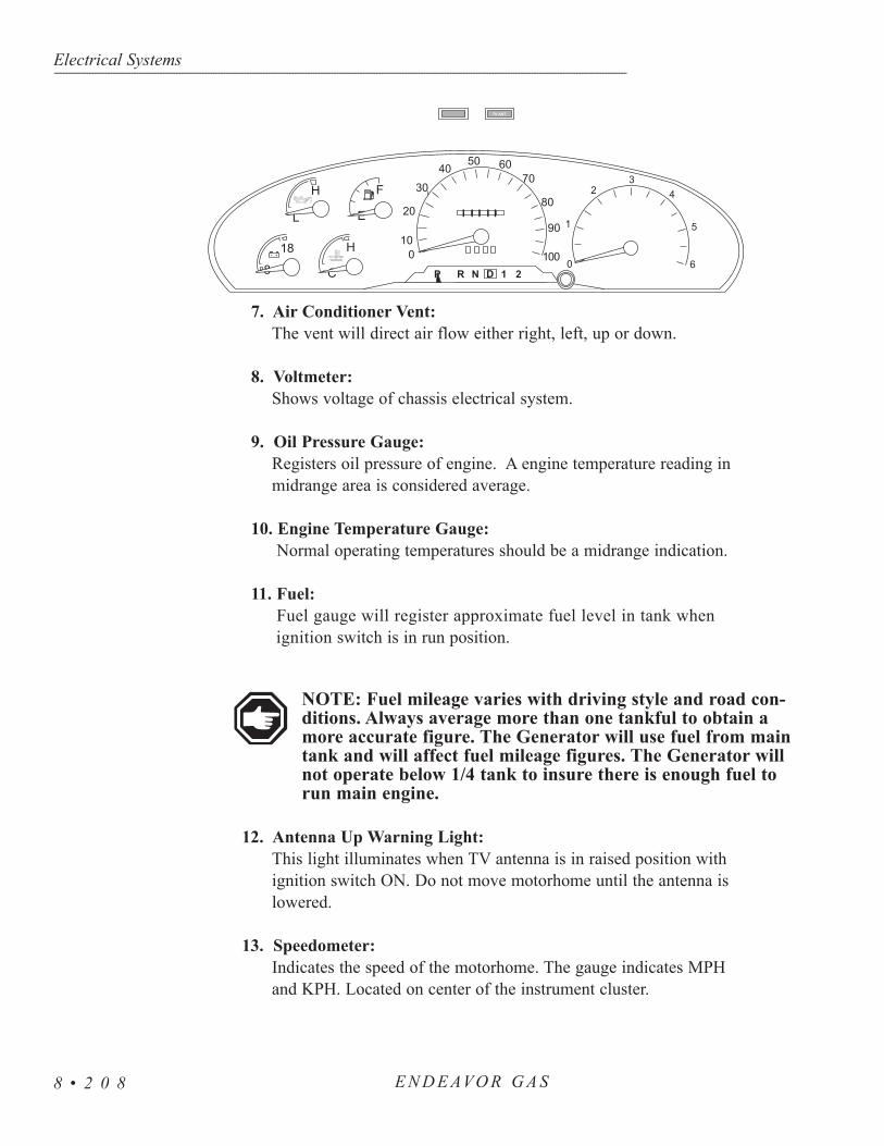
7. Air Conditioner Vent:The vent will direct air flow either right, left, up or down.
8. Voltmeter:Shows voltage of chassis electrical system.
9. Oil Pressure Gauge:Registers oil pressure of engine. A engine temperature reading inmidrange area is considered average.
10. Engine Temperature Gauge:Normal operating temperatures should be a midrange indication.
11. Fuel:Fuel gauge will register approximate fuel level in tank when ignition switch is in run position.
NOTE: Fuel mileage varies with driving style and road con-ditions. Always average more than one tankful to obtain amore accurate figure. The Generator will use fuel from maintank and will affect fuel mileage figures. The Generator willnot operate below 1/4 tank to insure there is enough fuel torun main engine.
12. Antenna Up Warning Light:This light illuminates when TV antenna is in raised position withignition switch ON. Do not move motorhome until the antenna islowered.
13. Speedometer:Indicates the speed of the motorhome. The gauge indicates MPHand KPH. Located on center of the instrument cluster.
Electrical Systems---------------------------------------------------------------------------------------------------------------------------------------------------------------------------------------------------------------------------------------------------------------------------------------------------------------------
E N D E AVO R G A S8 • 2 0 8
TV ANT.
C
E
8
L
H F
H180
5
6
43
1
2
+- 010
20
30
4050 60
70
80
90
100P R N D 1 2

14. Odometer:The odometer indicates the actual mileage of the motorhome.
15. Trip meter: The trip meter will display the current mileage of the trip since thelast reset.
16. Reset Button:Used to reset the trip meter counter to zero.
17. Shift Selector:The indicator shows the position on the transmission.
P - Indicates Park.R - Indicates Reverse.N - Indicates Neutral.D - Indicates Drive.1 - Indicates Lower Drive.2 - Indicates Lower Drive.
18. Tachometer:Displays engine speed in revolutions per minute (RPM).Tachometer reads output pulse of alternator. If tachometer quits orindicates improperly, have alternator checked immediately.
19. Gen ON/OFF:Starts and stops generator from the dash area.
20. Radio power switch:Turns radio on and off independent of main switch on radio.
21. Radio :Complete instructions for operation of radio are in your Owner’sInformation Packet.
Electrical Systems------------------------------------------------------------------------------------------------------------------------------------------------------------------------------------------------------------------------------------------------------------------------------------------------------------------
E N D E AVO R G A S 8 • 2 0 9
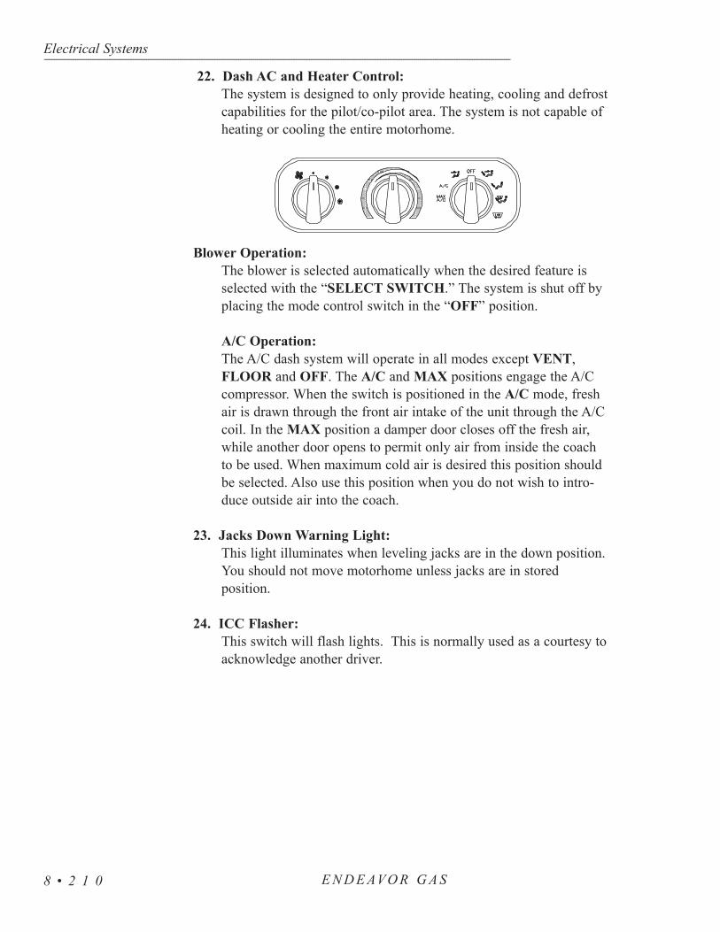
22. Dash AC and Heater Control:The system is designed to only provide heating, cooling and defrost capabilities for the pilot/co-pilot area. The system is not capable ofheating or cooling the entire motorhome.
Blower Operation:The blower is selected automatically when the desired feature isselected with the “SELECT SWITCH.” The system is shut off byplacing the mode control switch in the “OFF” position.
A/C Operation:The A/C dash system will operate in all modes except VENT,FLOOR and OFF. The A/C and MAX positions engage the A/Ccompressor. When the switch is positioned in the A/C mode, freshair is drawn through the front air intake of the unit through the A/Ccoil. In the MAX position a damper door closes off the fresh air,while another door opens to permit only air from inside the coachto be used. When maximum cold air is desired this position shouldbe selected. Also use this position when you do not wish to intro-duce outside air into the coach.
23. Jacks Down Warning Light:This light illuminates when leveling jacks are in the down position. You should not move motorhome unless jacks are in storedposition.
24. ICC Flasher:This switch will flash lights. This is normally used as a courtesy toacknowledge another driver.
Electrical Systems---------------------------------------------------------------------------------------------------------------------------------------------------------------------------------------------------------------------------------------------------------------------------------------------------------------------
E N D E AVO R G A S8 • 2 1 0

Air Distribution Switch (Mode Control):This switch is used to direct air where it is needed to maximize the comfort of the motorhome.
MAX A/C - Recirculated air is drawn from the passenger area and discharged through the dash louvers.
A/C - Fresh Air is drawn from outside into the system and discharged through the dash louvers.
VENT - Fresh air is drawn in and discharged throughout the dash and defrost louvers.
OFF - The blower motor does not operate. The fresh air inlet door will close minimizing outside air infiltration into the motorhome.
BI-LEVEL - Fresh air is drawn in and discharged through the dash, floor and defrost louvers.
FLOOR - Fresh air is drawn in and discharged through the floor louvers. A small amount of air is used to defrost the windshield.
MIX - Fresh air is drawn in and discharged through the floor and defrost louvers. The A/C system operates to dehumidify the discharged air.
DEFROST - Fresh air is drawn in and discharged through the defrost louvers. The A/C system operates to dehumidify the discharged air.
Temperature Control Switch:This switch controls an electric water valve regulating the amount of engine coolant passing through the heating and cooling coils in the system. Rotating to the red area provides warmer air; rotating to the blue area provides cooler air.
Blower Control Switch:The switch controls the speed of the blower motor, which is one of the best and most effective ways of controlling the temperature. The switch providesfour speeds in all modes except OFF.
Electrical Systems------------------------------------------------------------------------------------------------------------------------------------------------------------------------------------------------------------------------------------------------------------------------------------------------------------------
E N D E AVO R G A S 8 • 2 1 1
A/C
MAXA/C
OFF

Operating tips and hints:Air intake and discharge temperatures are greatly affected by ambient
temperature and relative humidity. A large amount of cooling capacity is used todehumidify air as well as cool it. After three to five minutes of A/C operationsthe discharged air temperature should be approximately 30º F cooler than thefresh or recirculated air entering the A/C system.
Winter Use:• De-ice the windshield using the DEFROST mode. • Air will heat up faster with a slower blower speed until normal operating
temperature ranges are reached.
Summer Use:• Close all windows and vents to hot, humid outside air.• MAX A/C and HI blower will provide quick cool down.• Use a lower blower speed to produce cooler air.
Troubleshooting:The dash A/C/Heat system uses a combination of compressed air
(developed by the chassis system), vacuum air (developed by the vacuum generator) and electric relays and vacuum switches. Therefore, any repair canbe classified in one of five categories:
• Electrical • Vacuum • Air Conditioner • Heater • Defroster
The motorhome compressed air tank must have adequate pressure to operate the vacuum generator or damper doors will not function. Also, the dashA/C/Heat unit must be switched ON to provide electric current to the relays,vacuum switches, etc. The dash A/C and heater system should be used monthlyto keep the compressor lubricated.
The following information is provided to assist in troubleshooting common operational problems which may occur.
No Heating:• A/C switch is turned off. • Blower switch is turned off.• Verify the proper engine coolant level. • Verify that the engine is reaching operating temperature. • Verify engine coolant is reaching water valve attached to unit. • Verify operation of water valve to permit engine coolant to pass through
valve to heater core. • Check unit fuses. • Check power supply to water valve and grounding. • Check wiring.• Engine thermostat faulty.
Electrical Systems---------------------------------------------------------------------------------------------------------------------------------------------------------------------------------------------------------------------------------------------------------------------------------------------------------------------
E N D E AVO R G A S8 • 2 1 2

No Cooling:• Check blower is operating, A/C switch is in A/C or Max position,
temperature control is turned to max cooling (blue area). • System fuses are not blown. • Condenser fan is operating. • Check power supply to unit and grounding of system. • Check wiring.• Coolant valve leaking.• Drive belt loose or broken.• Compressor Clutch inoperative, will not engage.• Expansion Valve faulty or frozen.• Thermostat control faulty.• Mode control switch faulty.• Compressor faulty.• Loss of refrigerant.
Reduced cooling:• Coolant valve not operating correctly. • Air passages obstructed. • Loose or worn drive belt.• Check blower and select switch. • Thermostat control valve faulty.• Expansion valve faulty.• Compressor faulty.• Low refrigerant charge.
Blower Does Not Operate or Runs Slow:• Check fuses. • Check for loose or corroded connection.• Check wiring. • Check ignition switch is “ON.” • Check blower and select switch. • Motor shaft seized.• Blower wheel out of alignment.
Damper Doors Do Not Operate:• Does motorhome air tank have pressure?• Check vacuum generator is being powered and producing vacuum. • Check vacuum line entering unit for vacuum. • Check that the vacuum solenoid mounted on unit are receiving power
from the mode switch. If operating properly, the vacuum solenoid will feel hot if current is engaging the solenoid.
• Check mode switch. • Check wiring. • Check for pinched vacuum line leading to the vacuum motor operating
the damper door in question.
Electrical Systems------------------------------------------------------------------------------------------------------------------------------------------------------------------------------------------------------------------------------------------------------------------------------------------------------------------
E N D E AVO R G A S 8 • 2 1 3

25. Back up Monitor: Used with the back up camera and will display the rear view of themotorhome.
The left lever arm contains the controls to operate the wipers, turn signalsand head light dimmer (turns brights on and off). This lever will also functionas the ICC Flash. Cruise control switches are located on the steering wheel andthe Overdrive Lock-Out is located on the end of shift lever.
The cruise control has a built in safety switch which will not allow the systemto operate until the speed of the motorhome is greater than 30 mph.
Electrical Systems---------------------------------------------------------------------------------------------------------------------------------------------------------------------------------------------------------------------------------------------------------------------------------------------------------------------
E N D E AVO R G A S8 • 2 1 4
STEERINGWHEEL -Operator Controls

To Set Speed:Push and release the ON/OFF switch on the steering wheel. Accelerate to
the desired speed which exceeds 30 mph. When obtained, hold the desiredspeed with the foot pedal while the SET switch is pressed and released. Onesecond after the switch is released the foot can be removed from the acceleratorpedal. Speed can be increased at any time with pressure on the acceleratorpedal. When the accelerator pedal is released the set speed will be resumed.
To Accelerate:When the cruise is engaged there are two ways to accelerate the motorhome.
Push and hold the SET switch on steering wheel to accelerate the motorhome.In using the SET switch, once the SET switch is released that speed will thenautomatically become the new default speed setting. The other option foracceleration is simply press to the accelerator pedal. When the acceleratorpedal is released the original programmed speed will be resumed.
To Coast:The COAST switch on steering wheel will allow the motorhome to coast
or slow in speed. When the COAST switch is pressed and held the motorhomewill slow in speed. When released the motorhome programmed set speed willautomatically set to the adjusted coast speed.
To Disengage:The cruise can be disengaged by two methods, simply press the brake pedal
and the current programmed speed is canceled. Pressing and releasing theON/OFF switch on steering wheel will erase the programmed speed and turnOFF the cruise function.
To Resume:When you disengage system with the brake you do not erase the set speed
from memory even if a complete stop is reached. To return to the chosen speeddrive to a speed above 30 mph then push the RESUME switch on steering wheel.The speed control program will take you back to that original set speed. If therate of acceleration is faster or slower than you like, use the accelerator toobtain a speed close to pre-set speed then push the RESUME switch. Thecruise control will automatically be turned off when ignition switch is turned off.
Electrical Systems------------------------------------------------------------------------------------------------------------------------------------------------------------------------------------------------------------------------------------------------------------------------------------------------------------------
E N D E AVO R G A S 8 • 2 1 5
Cruise Control

The control for the steering wheel tilt is a lever located on the steering columnnear the dash. Pulling the lever will allow changes to be made in the tilt of thesteering wheel. Adjust the wheel to the desired position then release the lever.
When the end of the arm is pressed in washer fluid will be dispensed fromthe system and the wipers will turn on momentarily. Holding the tip pushed influid will continue to be dispensed until the tip is released.
Wiper operations are controlled when rotating the end of arm. When the endof the arm is rotated from OFF to DELAY the wipers will turn on and a timedelay between wipes (ranging from 45 seconds to 2 seconds) will occur. Theamount of delay time changes as arm end is rotated. A continuous low or highspeed can be obtained by rotating the arm end to appropriate position. Thewipers will be turned OFF with the switch in the OFF position.
Moving the arm upward will activate the right hand turn signal circuitry. Adownward movement will activate the left hand turn signal circuitry. When theheadlights are ON pushing the arm away from steering wheel will switch theheadlights from low to high beam. This position will require a slight pulltowards the steering wheel to change from high to low beam. There is blueheadlight indicator in the dash cluster which indicates when high beams areselected. The headlight ICC circuitry can be operated by momentarily pullingthe arm all the way up towards the steering wheel and releasing. This procedurewhen repeated several times in succession will flash the headlights.
The lock out overdrive is for towing or direct drive transmission operation.Push in on the button located on end of shift lever and the indicator light on thelever dash cluster will illuminate. This should be engaged for mountain driving.Return to overdrive operation by pushing the button in and release it. The indicatorlight on the lever will go out. This is the normal indication.
The flasher button is located on the top of the steering column.
• To turn four way flasher on, push in on flasher button.This will release the switch and activate the flasherscircuitry.
• To shut off the flasher again push in on the push button,locking the button inward.
Electrical Systems---------------------------------------------------------------------------------------------------------------------------------------------------------------------------------------------------------------------------------------------------------------------------------------------------------------------
E N D E AVO R G A S8 • 2 1 6
Tilt Steering Wheel
Wiper/WasherOperation
Headlight BeamChange & TurnSignals
Overdrive Lock-OutSwitch
Hazard Flasher

Interior Lights:• Sidewall - 1076• Dinette Light - 1141• Double Pancake - Bulb 1141• Single Pancake - Bulb 1141• Cosmetic Light - 9-019C• Map Light - Bulb 1003• Fluorescent Light - Phillips F8T5/CW
Exterior Lights:• Engine Light - GE 232• Porch/Off Door Service Light - Bulb 1003• Red Clearance - Bulb 194• Amber Clearance - Bulb 194• Storage Lights - 168• Systems Compartment - 1141• Tail Light Turn Signal (Top) - 3156• Tail Light Brake/Tail (Center) - 3457• Tail Light Back Up (Bottom) - 3156• Third Brake Light - 562• License Plate - Order Complete Assembly• Front Amber Park (Outside Top) - 194• Front Amber Turn/Park (Outside Bottom) - 1157• Front Amber Turn (Inside Top) - 1156• Front Headlight (Inside Bottom) HB519007
Electrical Systems------------------------------------------------------------------------------------------------------------------------------------------------------------------------------------------------------------------------------------------------------------------------------------------------------------------
E N D E AVO R G A S 8 • 2 1 7
BULB USAGE

Electrical Systems------------------------------------------------------------------------------------------------------------------------------------------------------------------------------------------------------------------------------------------------------------------------------------------------------------------
8 • 2 1 8E N D E AVO R G A S

GASSECTION 9
SPECIFICATIONS & DIAGRAMS
CHART - TIRE • 221CHART - COMMON PARTS • 221CHART - SPECIFICATIONS • 222
ENGINE SPECS • 223TIRE BLOCKING METHODS • 223
CHASSIS LOG • 224GLOSSARY OF TERMS • 228
INDEX • 231
9


Specifications & Diagrams------------------------------------------------------------------------------------------------------------------------------------------------------------------------------------------------------------------------------------------------------------------------------------------------------------------
E N D E AVO R G A S 9 • 2 2 1
TIRE - CHART
COMMONPARTS
- CHART
TIRESIZE
8R19.5
225/70R19.5
245/70R19.5
265/70R19.5
9R22.5
10R22.5
11R22.5
12R22.5
245/75R22.5
255/70R22.5
265/75R22.5
275/80R22.5
295/75R22.5
295/80R22.5
315/80R22.5
285/75R24.5
MAXSpeedRating(MPH)
75
75
75
75
65
65
75
65
75
75
75
75
75
75
75
75
Dual (D)
Single(S)
DSDSDSDSDSDSDS
DSDSDS
DS
DS
DS
DSDSDS
65
23502410
31203190
36903770
702460254027202895
34153640
32703370
38704000
32603470
35853815
752570268028603040
35153740
34103560
40404210
34253645
37654005
40404070
46904725
47404770
802680280030003195
36553890
3750397035503730
4200441047604990
51905450
36403860
39704190
42054255
48854945
48555480
49304990
852780293031153315
3875(F)4080(F)
3930418036903890
4375461049505220
53905690
37403980
41104370
43704440
48555265
50705155
51005750
5840641552055210
902880306032453450
39404190
4095435538204050
45204790
51205430
55905920
38904140
42754550
45254620
50805515
52605370
53356020
6070667053105420
9529803170
3415(F)3640(F)
40754335
43004540
3950(F)4210
46704970
53005640
57806140
40804300
44104675
46854800
53055755
54405510
55706285
6395694054955675
10030703280
4375(G)4545(G)
44054685
4350
4875(F)5150(F)
54705840
59606370
41904455
44554895
4805(G)4975
55256000
5675(G)5780
5805655065407190
5675(G)5835
10531603400
45604850
4500(F)
49705320
5750(G)6175(G)
61506590
43354610
46105065
5150
57456235
58005980
6035681067707440
6040
1103375(F)3500(F)
48055070
51105490
5800(H)6240
63206790
4410(G)4675(G)
46755205
5205(G)
59656475
6005(H)6175(G)
6265707069407610
6175(G)
115
48605170
5250(G)5680(G)
6430
65007010
5070(H)5510(H)
61806710
63706490732072107920
120
5070(G)5355(G)
6610(H)
6750(H)7390(H)
6395(H)6940(H)
6610(H)67207580
7610(J)8270(J)
125
6940(H)7830(H)
I N F L AT I O N P R E S S U R E
-
P S I
COMPONENT
Air filter
Battery
Fuel filter
Oil Filter
PCV Valve
Spark Plugs
6.8 L V10 ENGINE
FA-1634
BXT-65 -750
FG872
FL-820-S
EV-233
AWSF 22E
Holiday Rambler is not the author of this chart and makes no representation orwarranty concerning the accuracy of the information disclosed by the chart. HolidayRambler is not responsible for the accuracy of the information disclosed or for anyerrors within the Tire Inflation Chart.

Specifications & Diagrams---------------------------------------------------------------------------------------------------------------------------------------------------------------------------------------------------------------------------------------------------------------------------------------------------------------------
E N D E AVO R G A S9 • 2 2 2
SPECIFICATIONS - CHART
MODELS 35SBD 35PBD 35WGS 36SGS 36PBD 36WGS
Water Heater 6 Gal. 6 Gal. 6 Gal. 6 Gal. 6 Gal. 6 Gal.
Grey Tank 45 Gal. 45 Gal. 43 Gal. 45 Gal. 45 Gal. 45 Gal.
Black Tank 45 Gal. 45 Gal. 45 Gal. 45 Gal. 45 Gal. 45 Gal.
Fresh Tank 67 Gal. 67 Gal. 67 Gal. 70 Gal. 55 Gal. 70 Gal.
LP Tank 32.9 Gal.
32.9 Gal.
32.9 Gal.
32.9 Gal.
32.9 Gal.
32.9 Gal.
TANK CAPACITIES (Approximate Gallons)
MODEL 35SBD 35PBD 35WGS 36SGS 36PBD 36WGS
GVWR20,500
lbs.20,500
lbs.20,500
lbs.20,500
lbs.20,500
lbs.20,500
lbs.
GCWR25,500
lbs.25,500
lbs.25,500
lbs.25,500
lbs.25,500
lbs.25,500
lbs.
GAWR (Front)
7,000 lbs
7,000 lbs
7,000 lbs
7,000 lbs
7,000 lbs 7,000 lbs
GAWR (Rear)
13,500 lbs
13,500 lbs
13,500 lbs
13,500 lbs
13,500 lbs
13,500 lbs
Wheel Base
228" 228" 228" 228" 228"
Overall Length
35' 11" 35' 36' 36' 36'
Overall Height
11'9" 11'9" 11'9" 11'9" 11'9" 11'9"
Interior Height
6'6" 6'6" 6'6" 6'6" 6'6" 6'6"
Interior Width
94.5" 94.5" 94.5" 94.5" 94.5" 94.5"
Exterior Width
100" 100" 100" 100" 100" 100"
CHASSIS SPECIFICATIONS

Specifications & Diagrams------------------------------------------------------------------------------------------------------------------------------------------------------------------------------------------------------------------------------------------------------------------------------------------------------------------
E N D E AVO R G A S 9 • 2 2 3
Engine SpecsEngine Type Ford V10 Gas Fuel Injection
Engine Size 6.8L V10
Cubic Inch Displacement 415
Tire Size 245/70RX19.5F
Fuel Tank (Approx. Gal) 75
Alternator (Amp) 130
Rear Axle Ratio 5.38:1
Overdrive Standard
Specifications & Diagrams---------------------------------------------------------------------------------------------------------------------------------------------------------------------------------------------------------------------------------------------------------------------------------------------------------------------
E N D E AVO R G A S9 • 2 2 4
Date Mileage Dealer Address Service/Remarks
CHASSIS LOG

Specifications & Diagrams------------------------------------------------------------------------------------------------------------------------------------------------------------------------------------------------------------------------------------------------------------------------------------------------------------------
E N D E AVO R G A S 9 • 2 2 5
Date Mileage Dealer Address Service/Remarks
CHASSIS LOG

Specifications & Diagrams---------------------------------------------------------------------------------------------------------------------------------------------------------------------------------------------------------------------------------------------------------------------------------------------------------------------
E N D E AVO R G A S9 • 2 2 6
Date Mileage Dealer Address Service/Remarks
CHASSIS LOG

Specifications & Diagrams------------------------------------------------------------------------------------------------------------------------------------------------------------------------------------------------------------------------------------------------------------------------------------------------------------------
E N D E AVO R G A S 9 • 2 2 7
Date Mileage Dealer Address Service/Remarks
CHASSIS LOG

Glossary---------------------------------------------------------------------------------------------------------------------------------------------------------------------------------------------------------------------------------------------------------------------------------------------------------------------
E N D E AVO R G A S9 • 2 2 8
AC Electricity - Alternating current also known as household power.
Ampere (Amp) - The unit of measure of electron flow rate of current through acircuit.
Ampere-hour (Amp-hr. AH) - A unit of measure for a battery electrical storagecapacity, obtained by multiplying the current in amperes by the time inhours of discharge (Example: a battery which delivers 5 amperes for 20hours, delivers 5 amperes times 20 hours, or 100 Amp-Hr. of capacity.)
Black Water - Term associated with the sewage holding tank. The toilet drainsdirectly into this tank.
British Thermal Unit (BTU) - The amount of heat required to raise or lowerthe temperature of one pound of water by 1° F.
Chassis Battery - Powers chassis 12V accessories and starts engine.
Circuit - An electric circuit is the path of an electric current. A closed circuithas a complete path. An open circuit has a broken or disconnected path.
City Water - A term associated with the water supply that you hook-up to whenyou are at campgrounds. It is called city water because you pull waterfrom a central source (like in a city) and not the fresh water tank.
Curbside - This refers to the side of the motorhome which faces the curb whenit is parked. Often called the door side.
Current (Alternating) (AC) - A current that varies periodically in magnitudeand direction. A battery does not deliver alternating current. Also referredto as shore power, utility power, inverter power, generator power, etc.
Current - The rate of flow of electricity or the movement rate of electronsalong a conductor. It is comparable to the flow of a stream of water. Theunit of measure for current is the ampere.
Cycle - In a battery, one discharge plus one recharge equals one cycle.
DC Electricity - Direct current also known as battery power.
Direct Current (DC) - Power that is stored in a battery bank or supplied byphotovoltaics, alternator, chargers and DC generators.
Drain Trap - This is a curve that is in all drains. Water is trapped in the curveand this creates a barrier so tank odors cannot escape through the drain.
GLOSSARY OFTERMS

Glossary------------------------------------------------------------------------------------------------------------------------------------------------------------------------------------------------------------------------------------------------------------------------------------------------------------------
E N D E AVO R G A S 9 • 2 2 9
Dry Camping - Camping in the motorhome when there is no city water hook-up or shore power. In other words, using only the water and power that isin the motorhome and not anything from another source.
Dump Station - Sites where you can drain your waste (grey) and sewage(black) tanks. In most states it is illegal to drain your tanks anywhereexcept at dump stations.
Dump Valve - Another name for the T-handle valve used to drain the sewage(black) and waste (grey tanks).
Egress Window - The formal name for the emergency window located in therear of the motorhome. Egress windows can be easily identified by theirred handles.
Full Hook-Up Site - A camp ground that has city water, shore power andsewer hook-ups or connections available.
Grey Water - Term associated with the waste water holding tank. Water fromthe sink drains, the shower and the washer/dryer (if equipped) go into thistank.
House Battery - Powers 12V lights and accessories inside motorhome.
LED - (Light Emitting Diode) Indicator light.
Low Point - The lowest point in the plumbing. Drains are placed here so thatwater will drain out of the lower end of the motorhome. These drainsmust be closed when you fill the water tank.
OHM - A unit for measuring electrical resistances.
Ohm’s Law - Express the relationship between volt (E), amperes (I) in anelectrical circuit with resistance (R). It can be expressed as follows: E =IR If any two of the three values are known the third value can be calcu-lated by using the above formula.
Road Side - This refers to the side of the motorhome which faces the roadwhen it is parked. Often called the off-door side.
Shore Line - This is the electrical cord which runs from the motorhome to thecamp ground 120 volt electrical supply.
Shore Line Plug - This is the 120 volt outlet that you can plug yourmotorhome into a campground.

Stinger - An arm attachment on a tow truck that is used to lift motorhomeslightly so that it can be towed.
Volt - The unit of measure for electric potential.
Watt - The unit for measuring electrical power, i.e., the rate of doing work, inmoving electrons by or against an electric potential.
Wet Cell Battery - A type of battery that uses liquid as an electrolyte. This typeof battery requires periodic maintenance such as cleaning the connectionsand checking the electrolyte level.
Glossary---------------------------------------------------------------------------------------------------------------------------------------------------------------------------------------------------------------------------------------------------------------------------------------------------------------------
E N D E AVO R G A S9 • 2 3 0

E N D E AVO R G A S 9 • 2 3 1
EEgress Exit Window.......................................Emergency Procedures...................................Energy Management System.........................Entertainment Center - Home........................Entry Door......................................................Entry Step.......................................................Exterior Care..................................................
FFans................................................................Fire Extinguisher............................................Furnace...........................................................
GGenerator 120 AC..........................................GFCI Breakers & Outlets..............................Glossary of Terms..........................................
H, IHitch - Using the Rear Receiver....................Interior Care...................................................
J, K, LLeveling System (Optional)...........................Limited Warranty ..........................................LP-Gas Consumption.....................................LP-Gas Detector.............................................LP-Gas Distribution Lines............................LP-Gas Regulator..........................................LP-Gas System..............................................LP-Gas Tank..................................................
M, NMicrowave Oven...........................................Microwave/Convection Oven (Optional)......Monitor Panel................................................
A30 Amp Distribution Panel (Inside)...............50 Amp Distribution Panel (110AC) (Optional).......................................................50 Amp Distribution Panel (12 Volt)(Optional)......................................................AC System - 120/240 Volt............................Air Conditioner - Roof ..................................Awnings..........................................................
BBacking Up A Motorhome.............................Battery Disconnect - House...........................Battery - How It Works..................................Breaking Camp...............................................Bulb Usage.....................................................
CCarbon Monoxide Detector............................Chart - Common Parts...................................Chart - Engine Specifications........................Chart - Chassis Specifications.......................Chart - Tank Capacities..................................Chart - Tire.....................................................Chassis Log....................................................Checklist - Pre-Trip Preparation....................Checklist - LP-Gas Emergency Procedures..Checklist - Set-up Procedures........................Citizen Band Radio Prewire (Optional).........Cold Weather Use..........................................Cooktop/Range...............................................Cooktop (Optional)........................................Customer Relations........................................
DDash Panel.....................................................DC System - 12 Volt......................................Dinette Bed Conversion (Optional)...............Door - Sliding................................................Driving Safety................................................Dry Camping Tips..........................................
188
189
193183114143
3018519836217
5822122322222222122426174331401641101127
2061841481422335
603719013613112965
14159115
18754228
2869
32 1317856,172179177171175
102105153,174
Index------------------------------------------------------------------------------------------------------------------------------------------------------------------------------------------------------------------------------------------------------------------------------------------------------------------

9 • 2 3 2 E N D E AVO R G A S 9 • 2 3 2
OOwner’s Record - Insurance............................Owner’s Record - Personal Property...............Owner’s Record - Serial Numbers..................
P, Q, RRadio - Dash....................................................Rear View System...........................................Refrigerator......................................................Reporting Safety Defects.................................
SService Suggestions.........................................Shore Power Hook-Up....................................Slide-Out Operation........................................Smoke Detector...............................................Sofa Bed Conversion......................................Specifications - Dimensions Chart.................Steering Wheel................................................Storage ............................................................Storage - Under Bed........................................
T, UTaking Delivery...............................................Tank Capacities - Chart...................................Tires.................................................................Tire “Blocking” Methods................................Toilet - Operating Instructions........................Towing Procedures..........................................
VViews...............................................................Vendor List......................................................
W, X, Y, ZWarranty Information File................................Washer/Dryer (Optional)..................................Water - City Hook-Up......................................Water Filter (Optional).....................................Water Heater.....................................................Water Pump......................................................Water System - Disinfecting Fresh Water........Water System - Troubleshooting......................Water System - Waste Drain & Sewage..........Water Tank - Fresh Water Fill..........................Water Tank - Fresh Gravity Fill.......................Winterizing - Fresh Water System...................Winterizing - Using Air Pressure.....................
111112
140289710
9186132551485321487148
81593922316138
5117
9123155157117155158158166154154166165
Index---------------------------------------------------------------------------------------------------------------------------------------------------------------------------------------------------------------------------------------------------------------------------------------------------------------------

Specifications & Diagrams------------------------------------------------------------------------------------------------------------------------------------------------------------------------------------------------------------------------------------------------------------------------------------------------------------------
9 • 2 3 3E N D E AVO R G A S
NOTES