Embed Size (px)
Citation preview
PaceMaster Bronze Basic
OWNER’S MANUAL
Manufactured by: Aerobics Inc., 34 Fairfield Place West Caldwell, NJ 07006, (973) 276-9700 www.pacemaster.com
Part # TMP1608 Rev. 03/17/08
2
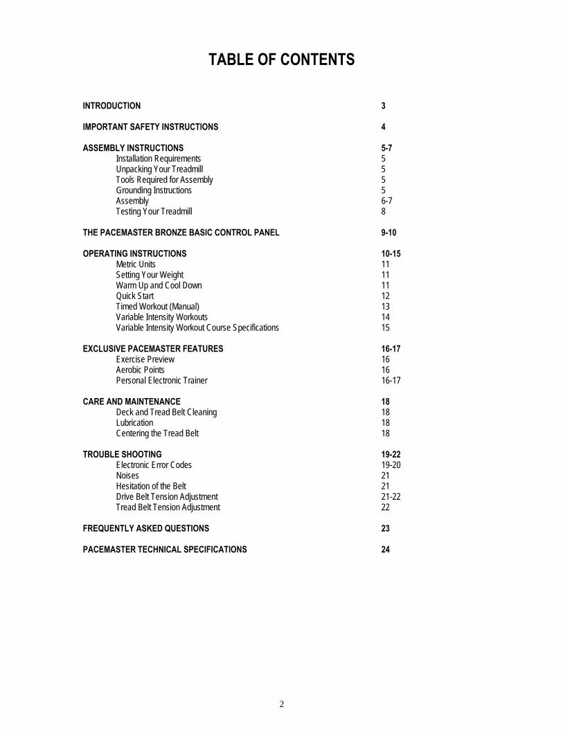
TABLE OF CONTENTS INTRODUCTION 3 IMPORTANT SAFETY INSTRUCTIONS 4 ASSEMBLY INSTRUCTIONS 5-7 Installation Requirements 5 Unpacking Your Treadmill 5 Tools Required for Assembly 5 Grounding Instructions 5 Assembly 6-7 Testing Your Treadmill 8 THE PACEMASTER BRONZE BASIC CONTROL PANEL 9-10 OPERATING INSTRUCTIONS 10-15 Metric Units 11 Setting Your Weight 11 Warm Up and Cool Down 11 Quick Start 12 Timed Workout (Manual) 13
Variable Intensity Workouts 14 Variable Intensity Workout Course Specifications 15 EXCLUSIVE PACEMASTER FEATURES 16-17
Exercise Preview 16 Aerobic Points 16 Personal Electronic Trainer 16-17
CARE AND MAINTENANCE 18
Deck and Tread Belt Cleaning 18 Lubrication 18 Centering the Tread Belt 18
TROUBLE SHOOTING 19-22 Electronic Error Codes 19-20 Noises 21 Hesitation of the Belt 21 Drive Belt Tension Adjustment 21-22 Tread Belt Tension Adjustment 22 FREQUENTLY ASKED QUESTIONS 23 PACEMASTER TECHNICAL SPECIFICATIONS 24

3
INTRODUCTION Congratulations and thank you for choosing PaceMaster – your partner in achieving your fitness goals and mastering your well-being. PaceMaster’s advanced digital technology allows your treadmill to process information instantly, anticipating and adjusting to meet your needs. Think of it as your own personal trainer. PaceMaster’s superior components and US manufacture ensure we produce treadmills of the highest quality while also offering excellent value for your dollar. PaceMaster treadmills have consistently received praise from a wide range of nationally recognized publications. To get the most from your PaceMaster, please read this owner’s manual carefully before starting to use the treadmill. The manual contains important information about the assembly, operation and maintenance of the machine.
Please ensure you read and fully understand all safety information. DANGER, CAUTION, or WARNING indicates important safety warnings throughout the manual. Failure to read and understand these warnings may result in personal injury or damage to your treadmill. Tip indicates a useful suggestion when installing, maintaining or using your treadmill. Your PaceMaster treadmill is capable of varying your workout by changing speed, incline and time. It can also measure the effect of your workout in a number of different ways. For example “Aerobic Points” (see page16) is a well tested method to set workout goals based on a desired level of overall fitness. Your PaceMaster treadmill can automatically calculate Aerobic Points for you. In this way your treadmill acts like your own personal trainer. Please take the time to familiarize yourself with the range of functions available. This will help you work with your PaceMaster treadmill for maximum efficiency to achieve your fitness goals and master your well-being. We wish you an enjoyable and rewarding partnership with your PaceMaster treadmill. This treadmill is in compliance with EN 957-2 class H.
The PaceMaster Bronze Basic treadmill is designed for home use only.

4
IMPORTANT SAFETY INSTRUCTIONS
Read these instructions before using your treadmill
CAUTION: Before starting any exercise program, contact your personal physician and have a complete physical. This is highly recommended if you have not been on a regular exercise program within the last year, or are over 35 years of age, or are overweight.
CAUTION: If at any time during your exercise program you find the exercise abnormally difficult or you encounter dizziness, feel faint, experience chest pains, feel as if your heart may be skipping beats, you experience forced heavy breathing after minimal exercise or severe pain in your legs, ankles, knees, etc. STOP EXERCISING and consult your physician.
WARNING: To reduce the risk of burns, fire, electrical shock or injury: • Never operate your PaceMaster treadmill without clipping the magnetic safety key to your clothing at waist level. • Your PaceMaster treadmill is not designed for use by children under the age of 18 without strict parental supervision. • Close supervision is necessary when the treadmill is used by or near children, disabled persons or pets. • Use your PaceMaster treadmill only for its intended use as described in this manual. Do not use accessories or attachments not recommended by Aerobics, Inc. • Never operate your PaceMaster treadmill if it has a damaged cord or plug, if it is not operating properly, if it has been dropped or damaged or if it has been immersed in water. Should any of these occur, contact your authorized PaceMaster retailer or service center for examination or repair. • Keep the cord away from heated surfaces. • Never drop or insert any object into any opening on the treadmill. • Do not use outdoors. • Always unplug your PaceMaster treadmill during an electrical storm or during extended periods of non-use. • Do not operate where aerosol (spray) products are being used or where oxygen is being administered. • Position the treadmill with a minimum of 4 feet (1219mm) of clearance between the rear of the treadmill and any wall or obstruction. • Do not allow anyone to reach under or be too near your PaceMaster while it is in use. • Do not attempt to mount or dismount the tread belt while it is running. • Never allow more than one person on your PaceMaster treadmill at any time. • Never move the treadmill while it is plugged into the electrical outlet. • When you are finished exercising, leave your PaceMaster treadmill in a non-elevated position to avoid toys and other objects from becoming trapped beneath. • Wear appropriate running or walking shoes and attire while exercising. • The treadmill should be turned off after each use by removing the safety magnetic key. • Never apply lubricant to the belt and deck. It is permanently lubricated at the factory and is maintenance free.
5
ASSEMBLY INSTRUCTIONS
Installation Requirements Your PaceMaster should be installed indoors on a flat, level surface near a 120Volt/ 15Amp outlet. PaceMaster requires a dedicated, non-switched outlet that is not part of a GFI (Ground Fault Interrupter) circuit, preferably no more than 5 feet from the outlet to eliminate the need for an extension cord. You must have a minimum of 4 feet of clearance between the rear of the treadmill and any wall or obstruction. TIP: If you are installing your PaceMaster on a carpeted surface, use a treadmill mat or a scrap piece of carpet underneath the treadmill to avoid soiling of the carpet. Deep pile carpet is not recommended. Unpacking Your Treadmill The PaceMaster treadmill is packed in five pieces:
• Frame assembly • Front handlebar assembly with Control Panel • Two side rails • Motor cover • Hardware package
Before assembling your treadmill, open the hardware package and verify that you have the following items: Two black side rail brackets Two #8 x ½” black sheet metal screws Two 1” fender washers 3/16” Allen wrench Four 1/4-20 x 3.5" black carriage bolt Magnetic safety key with garment clip Two 1/4-20 x 4” black slotted head bolts Owner’s Manual Six 1/4-20 kep nuts Warranty registration card If any parts are missing, contact the authorized PaceMaster retailer where you purchased your PaceMaster treadmill. Tools Required for Assembly
• 3/16" Allen wrench (supplied) • 7/16” combination wrench • Phillips head screwdriver • Slotted Head Screwdriver
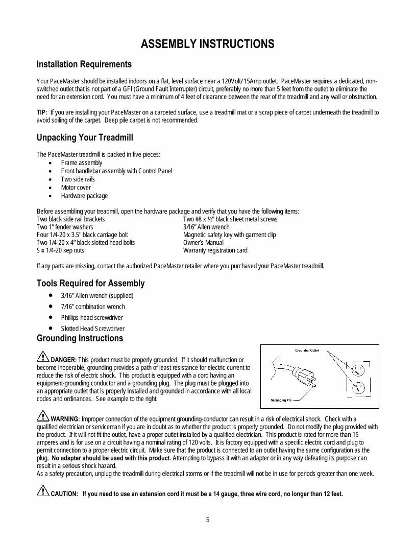
Grounding Instructions
DANGER: This product must be properly grounded. If it should malfunction or become inoperable, grounding provides a path of least resistance for electric current to reduce the risk of electric shock. This product is equipped with a cord having an equipment-grounding conductor and a grounding plug. The plug must be plugged into an appropriate outlet that is properly installed and grounded in accordance with all local codes and ordinances. See example to the right.
WARNING: Improper connection of the equipment grounding-conductor can result in a risk of electrical shock. Check with a qualified electrician or serviceman if you are in doubt as to whether the product is properly grounded. Do not modify the plug provided with the product. If it will not fit the outlet, have a proper outlet installed by a qualified electrician. This product is rated for more than 15 amperes and is for use on a circuit having a nominal rating of 120 volts. It is factory equipped with a specific electric cord and plug to permit connection to a proper electric circuit. Make sure that the product is connected to an outlet having the same configuration as the plug. No adapter should be used with this product. Attempting to bypass it with an adapter or in any way defeating its purpose can result in a serious shock hazard. As a safety precaution, unplug the treadmill during electrical storms or if the treadmill will not be in use for periods greater than one week.
CAUTION: If you need to use an extension cord it must be a 14 gauge, three wire cord, no longer than 12 feet.

6
Figure 1
Purse Lock Clip
Shown Closed
ASSEMBLY INSTRUCTIONS Assembly Step One: (see figure 1) Carefully place the bottom of the handlebar (1) on the frame (2) so the two holes in the plate at the bottom of the handlebar line up with the holes in the frame. Insert the 3.5” carriage bolts (3) through the handlebar and the frame. Install a 1/4-20 kep nut (4) to each carriage bolt to keep the handlebar in place. Follow the same procedure for the other side of the handlebar. Do not tighten any nuts until both sides are bolted in place.
CAUTION: Make sure the treadmill is NOT plugged into the electrical outlet until assembly is competed. Step Two: (see figure 2) With the handlebar bolted in place, plug the black wire harness (5) into the socket (6) on the power supply board. Twist open the purse clip at (7a) insert the wire harness (5) and secure the purse clip. Confirm the wire harness is positioned as shown at point 5 above. Follow the same procedure for purse clip (7b).
Figure 2 7a 6 5 7b
7
Figure 3
Figure 4
Figure 5
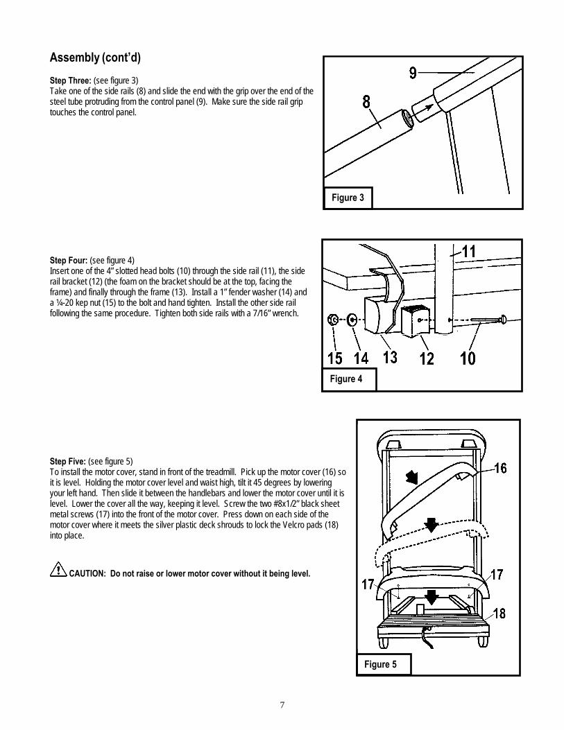
Assembly (cont’d) Step Three: (see figure 3) Take one of the side rails (8) and slide the end with the grip over the end of the steel tube protruding from the control panel (9). Make sure the side rail grip touches the control panel. Step Four: (see figure 4) Insert one of the 4” slotted head bolts (10) through the side rail (11), the side rail bracket (12) (the foam on the bracket should be at the top, facing the frame) and finally through the frame (13). Install a 1” fender washer (14) and a ¼-20 kep nut (15) to the bolt and hand tighten. Install the other side rail following the same procedure. Tighten both side rails with a 7/16” wrench. Step Five: (see figure 5) To install the motor cover, stand in front of the treadmill. Pick up the motor cover (16) so it is level. Holding the motor cover level and waist high, tilt it 45 degrees by lowering your left hand. Then slide it between the handlebars and lower the motor cover until it is level. Lower the cover all the way, keeping it level. Screw the two #8x1/2” black sheet metal screws (17) into the front of the motor cover. Press down on each side of the motor cover where it meets the silver plastic deck shrouds to lock the Velcro pads (18) into place.
CAUTION: Do not raise or lower motor cover without it being level.
8
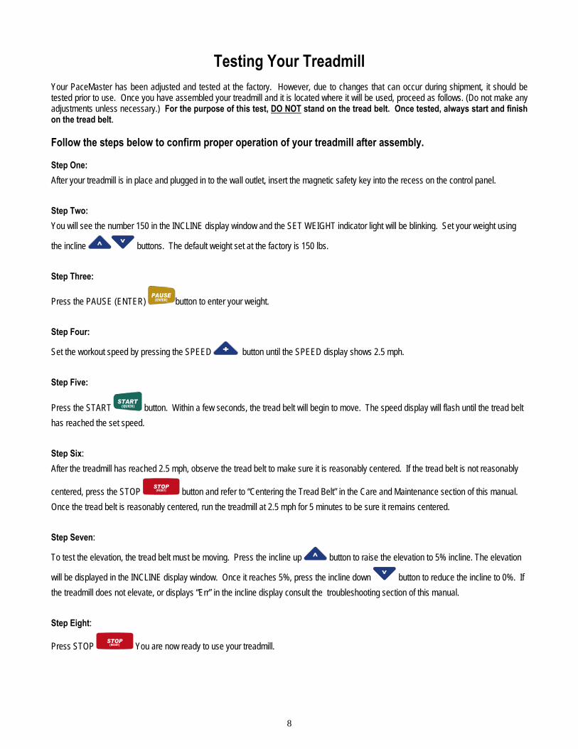
Testing Your Treadmill Your PaceMaster has been adjusted and tested at the factory. However, due to changes that can occur during shipment, it should be tested prior to use. Once you have assembled your treadmill and it is located where it will be used, proceed as follows. (Do not make any adjustments unless necessary.) For the purpose of this test, DO NOT stand on the tread belt. Once tested, always start and finish on the tread belt. Follow the steps below to confirm proper operation of your treadmill after assembly. Step One: After your treadmill is in place and plugged in to the wall outlet, insert the magnetic safety key into the recess on the control panel.
Step Two: You will see the number 150 in the INCLINE display window and the SET WEIGHT indicator light will be blinking. Set your weight using
the incline buttons. The default weight set at the factory is 150 lbs. Step Three:
Press the PAUSE (ENTER) (ENTER) button to enter your weight. Step Four:
Set the workout speed by pressing the SPEED button until the SPEED display shows 2.5 mph. Step Five:
Press the START (QUICK) button. Within a few seconds, the tread belt will begin to move. The speed display will flash until the tread belt has reached the set speed. Step Six: After the treadmill has reached 2.5 mph, observe the tread belt to make sure it is reasonably centered. If the tread belt is not reasonably
centered, press the STOP (RESET) button and refer to “Centering the Tread Belt” in the Care and Maintenance section of this manual. Once the tread belt is reasonably centered, run the treadmill at 2.5 mph for 5 minutes to be sure it remains centered. Step Seven:
To test the elevation, the tread belt must be moving. Press the incline up button to raise the elevation to 5% incline. The elevation
will be displayed in the INCLINE display window. Once it reaches 5%, press the incline down button to reduce the incline to 0%. If the treadmill does not elevate, or displays “Err” in the incline display consult the troubleshooting section of this manual. Step Eight:
Press STOP (RESET) You are now ready to use your treadmill.
9
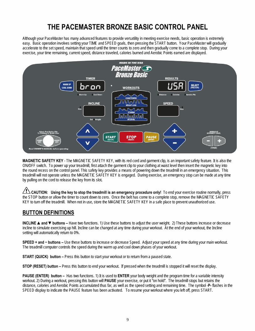
THE PACEMASTER BRONZE BASIC CONTROL PANEL Although your PaceMaster has many advanced features to provide versatility in meeting exercise needs, basic operation is extremely easy. Basic operation involves setting your TIME and SPEED goals, then pressing the START button. Your PaceMaster will gradually accelerate to the set speed, maintain that speed until the timer counts to zero and then gradually come to a complete stop. During your exercise, your time remaining, current speed, distance traveled, calories burned and Aerobic Points earned are displayed.
MAGNETIC SAFETY KEY - The MAGNETIC SAFETY KEY, with its red cord and garment clip, is an important safety feature. It is also the ON/OFF switch. To power up your treadmill, first attach the garment clip to your clothing at waist level then insert the magnetic key into the round recess on the control panel. This safety key provides a means of powering down the treadmill in an emergency situation. This treadmill will not operate unless the MAGNETIC SAFETY KEY is engaged. During exercise, an emergency stop can be made at any time by pulling on the cord to release the key from its slot.
CAUTION: Using the key to stop the treadmill is an emergency procedure only! To end your exercise routine normally, press the STOP button or allow the timer to count down to zero. Once the belt has come to a complete stop, remove the MAGNETIC SAFETY KEY to turn off the treadmill. When not in use, store the MAGNETIC SAFETY KEY in a safe place to prevent unauthorized use. BUTTON DEFINITIONS INCLINE ▲and ▼buttons – Have two functions. 1) Use these buttons to adjust the user weight. 2) These buttons increase or decrease incline to simulate exercising up hill. Incline can be changed at any time during your workout. At the end of your workout, the Incline setting will automatically return to 0%. SPEED + and − buttons – Use these buttons to increase or decrease Speed. Adjust your speed at any time during your main workout. The treadmill computer controls the speed during the warm up and cool down phases of your workout. START (QUICK) button – Press this button to start your workout or to return from a paused state. STOP (RESET) button – Press this button to end your workout. If pressed when the treadmill is stopped it will reset the display. PAUSE (ENTER) button – Has two functions. 1) It is used to ENTER your body weight and the program time for a variable intensity workout. 2) During a workout, pressing this button will PAUSE your exercise, or put it "on hold". The treadmill stops but retains the distance, calories and Aerobic Points accumulated thus far, as well as the speed setting and remaining time. The symbol -P- flashes in the SPEED display to indicate the PAUSE feature has been activated. To resume your workout where you left off, press START.
bron uSA
10
THE PACEMASTER BRONZE BASIC CONTROL PANEL (cont’d) Warm Up / Cool Down button – Prior to starting, this button allows you to add or remove a 5-minute Warm Up and/or 5-minute Cool Down phases to your workout. During Warm Up, pressing the Warm Up / Cool Down button discards the remaining warm up time and advances you to the main workout phase. During the main workout, pressing the Warm Up / Cool Down button discards the remaining time and starts the Cool Down phase. Fitness experts strongly recommend a warm up before and a cool down following your aerobic workouts. See the WARM UP and COOL DOWN section in this manual for details. SELECT (PREVIEW) button – Has two functions. 1) Prior to and during your workout this button is used to select the value (distance, calories, or aerobic points) displayed in the Results window. During your workout you can press and hold this button until the word “SCAn” appears in the Results display, now each value (distance, calories, and points) will be displayed for 3 seconds on a rotating cycle. 2) It is used to change the treadmill setting from English units to Metric units (see “Metric units” page 11). WORKOUTS buttons – In the WORKOUTS window press the desired Variable Intensity Workout profile to select that workout, your selection is confirmed by the workout indicator light illuminating. For details, refer to the VARIABLE INTENSITY WORKOUTS section in this manual. WORKOUT INTENSITY LEVEL (TIMER) buttons – Has two functions. 1) Use these buttons to set your workout time for both a TIMED WORKOUT and a VARIABLE INTENSITY WORKOUT. 2) Use these buttons to set or change the workout intensity level in a VARIABLE INTENSITY WORKOUT. DISPLAYS RESULTS display – Displays Distance, Calories and Aerobic Points. Additionally, during the selection or use of a Variable Intensity Workout the chosen or current intensity level is displayed. TIMER display – Displays time in minutes and seconds (mm:ss) up to 59 minutes and 59 seconds. Times of 1 hour to a maximum of 8 hours are displayed as hours and minutes (– h: mm), with the dash as the first digit. For example, – 1:15 represents one hour and 15 minutes. In Quick Start, the TIME display counts up (elapsed time). In other modes of operation the TIME display counts down (time remaining). When using warm up and/or cool down, time will display as a 5-minute countdown for the warm up phase, a countdown for the main exercise phase and then a 5-minute countdown for the cool down phase. SPEED display – Displays Speed from 0.5 mph to 11.0 mph, in 0.1 mph increments. Prior to starting, the displayed value is the Speed the treadmill will seek once START is pressed. Once your workout has begun, the current Speed is displayed. The speed display will flash until the set speed is reached. INCLINE display – Displays Incline from 0% to 15.0%, in 0.5% increments. Prior to starting, the displayed value is the current incline or the incline the treadmill will seek once START is pressed. Once your workout has begun, the current Incline is displayed. INDICATOR LIGHTS Set Weight indicator – 3 seconds after the magnetic safety key is inserted, the Set Weight indicator flashes and the last entered body weight is shown on the INCLINE display. Body weight can be adjusted using the INCLINE buttons. Once the desired setting is displayed, press PAUSE (ENTER). INCLINE Max indicator – When illuminated during the selection of a Variable Intensity Workout, the displayed Incline is the maximum incline that will be encountered during the selected workout and intensity level. SPEED Max indicator – When illuminated during selection of a Variable Intensity Workout, the displayed speed is the maximum speed that will be encountered during the selected workout and intensity level. WARM Up and COOL DOWN indicators – Illuminated Warm Up or Cool Down indicators show that these routines will be part of the workout. When in the Warm Up or Cool Down mode, the appropriate indicator will blink. DISTANCE, CALORIES, And AEROBIC POINTS indicators – They tell you which value is being displayed in the Results window.
11
OPERATING INSTRUCTIONS
Initially, you may want to keep both hands on the side rails until you feel comfortable walking on your PaceMaster. Once you feel comfortable, try removing your hands to let them swing naturally, as you would when walking outdoors. Always hold on to the side rail or front handle bar with one hand when operating the buttons of the control panel. THE FIRST STEP Stand on the center of the treadmill belt. Attach the garment clip on the end of the magnetic safety key to your clothing at waist level. Insert the safety key into the recess on the control panel keyboard. METRIC UNITS PaceMaster treadmills can be configured to operate in English (lbs, mph, and miles) or Metric units (kg, kph, and kilometers) of measure. To determine the present configuration of your PaceMaster insert the magnetic key, if “USA” is displayed in the “RESULTS” window it is configured in English, if “Eur” is displayed in the “RESULTS” window, it is configured in Metric. To change between English and Metric insert the magnetic key, as soon as the current setting (USA or EUR) is displayed in the Results window, press and hold the SELECT (PREVIEW) button until the setting changes. Press PAUSE (ENTER) to confirm the selection. SETTING YOUR WEIGHT Your PaceMaster calculates caloric expenditure based on the formula developed by the American College of Sports Medicine. To ensure accuracy, your weight is required. Once the magnetic key has been inserted, the default weight of 150 lbs. (68 kg.) is shown in the INCLINE display and the SET WEIGHT indicator will be blinking. By pressing the INCLINE up or down buttons, you will increase or decrease the weight value, press PAUSE (ENTER) when done. WARM UP AND COOL DOWN By warming up prior to beginning the aerobic phase of your workout, you accomplish 2 goals; you stretch and warm up the muscles of the back and extremities and create a slight acceleration of the heart rate so that the body can move gradually into the higher heart rate of the aerobic phase. The aerobic phase should be followed by a minimum 5-minute cool down in which you keep moving at a slower pace. This allows your heart rate to gradually decline and your body to gently adjust to the end of a workout instead of abruptly stopping. The cool down phase also allows blood to be pumped from the lower extremities back to the central circulatory system. Simply put, the function of warming up and cooling down is to ease you from a resting state into an active state and back to a resting state. The treadmill’s computer, based on your main exercise starting and finishing speeds respectively, automatically calculates warm up and cool down speeds. When in the warm up mode, the TIME display window counts down from 5 minutes and the Warm Up indicator light will blink. When in the Cool Down mode, the TIME display window counts down from 5 minutes and the Cool Down indicator light will blink. To add warm up and/or cool down to a TIMED workout press the Warm Up / Cool Down button. The indicator light will blink, indicating that the desired mode has been added to your workout. You will also notice that the workout time increases by 5 minutes for each addition. To shorten the warm up mode, press the Warm Up / Cool Down button once. Warm up will be ended and you will advance into the main exercise. To shorten the main exercise, press the Warm Up / Cool Down button and you will automatically begin the cool down phase. To end the cool down, press STOP and your session will come to a close. A cool down phase can be added to any workout (even if it wasn’t chosen prior to beginning the workout) by pressing the Warm Up / Cool Down button. Now you are ready to choose your workout mode. Whether it is Quick Start, Timed Workout (Manual), or one of the four Variable Intensity Workouts, the following pages give you step-by-step instructions on how to use each workout.
12
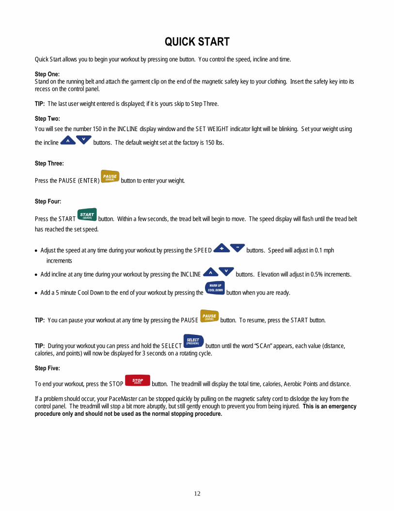
QUICK START Quick Start allows you to begin your workout by pressing one button. You control the speed, incline and time. Step One: Stand on the running belt and attach the garment clip on the end of the magnetic safety key to your clothing. Insert the safety key into its recess on the control panel. TIP: The last user weight entered is displayed; if it is yours skip to Step Three. Step Two: You will see the number 150 in the INCLINE display window and the SET WEIGHT indicator light will be blinking. Set your weight using
the incline buttons. The default weight set at the factory is 150 lbs. Step Three:
Press the PAUSE (ENTER) (ENTER) button to enter your weight. Step Four:
Press the START (QUICK) button. Within a few seconds, the tread belt will begin to move. The speed display will flash until the tread belt has reached the set speed. • Adjust the speed at any time during your workout by pressing the SPEED buttons. Speed will adjust in 0.1 mph
increments
• Add incline at any time during your workout by pressing the INCLINE buttons. Elevation will adjust in 0.5% increments.
• Add a 5 minute Cool Down to the end of your workout by pressing the button when you are ready.
TIP: You can pause your workout at any time by pressing the PAUSE (ENTER) button. To resume, press the START button.
TIP: During your workout you can press and hold the SELECT (PREVIEW) button until the word “SCAn” appears, each value (distance, calories, and points) will now be displayed for 3 seconds on a rotating cycle. Step Five:
To end your workout, press the STOP (RESET) button. The treadmill will display the total time, calories, Aerobic Points and distance. If a problem should occur, your PaceMaster can be stopped quickly by pulling on the magnetic safety cord to dislodge the key from the control panel. The treadmill will stop a bit more abruptly, but still gently enough to prevent you from being injured. This is an emergency procedure only and should not be used as the normal stopping procedure.

13
TIMED WORKOUT (MANUAL) Timed Workout allows you to choose the length of time and the degree of intensity for your workout. You can make speed and incline adjustments at any time during the workout. Step One: Stand on the running belt and attach the garment clip on the end of the magnetic safety key to your clothing. Insert the safety key into its recess on the control panel. TIP: The last user weight entered is displayed; if it is yours skip to Step Three. Step Two: You will see the number 150 in the INCLINE display window and the SET WEIGHT indicator light will be blinking. Set your weight using
the incline buttons. The default weight set at the factory is 150 lbs. Step Three:
Press the PAUSE (ENTER) (ENTER) button to enter your weight. Step Four: Enter the starting speed by press the SPEED button until the desired speed appears in the SPEED display window. Speed can be adjusted at any time during your workout. Step Five:
Enter the workout time by pressing the WORKOUT INTENSITY LEVEL (TIMER) buttons until the desired workout time appears. If you hold either of the buttons down the time scrolls quickly.
• If you wish to include warm up and/or cool down to your workout, press the button until the indicator light next to the desired mode is illuminated. You will notice that your workout time will automatically increase by 5 minutes for each addition. For details, refer to the WARM UP AND COOL DOWN section in this manual.
• Adjust incline by pressing the INCLINE buttons. Elevation is adjusted in 0.5% increments. Step Six:
Press START (QUICK) and your PaceMaster will gradually accelerate until it reaches the entered speed. Step Seven:
To end your workout, either allow the timer to count down to zero or press the STOP (RESET) button. The treadmill will display the total time, calories, Aerobic Points and distance.
TIP: You can pause your workout at any time by pressing the PAUSE (ENTER) button. To resume, press the START (QUICK) button.
TIP: During your workout you can press and hold the SELECT (PREVIEW) button until the word “SCAn” appears in the RESULTS display, each value (distance, calories, and points) will now be displayed for 3 seconds on a rotating cycle. If a problem should occur, your PaceMaster can be stopped quickly by pulling on the magnetic safety cord to dislodge the key from the control panel. The treadmill will stop a bit more abruptly, but still gently enough to prevent you from being injured. This is an emergency procedure only and should not be used as the normal stopping procedure.
14
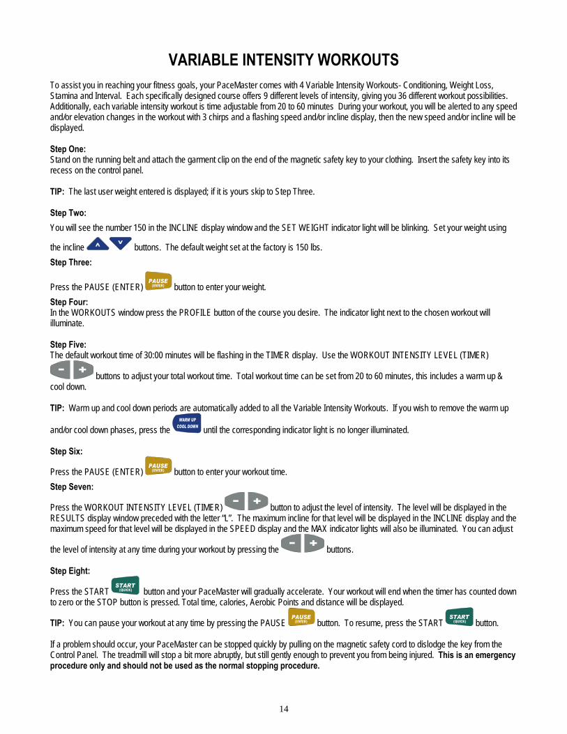
VARIABLE INTENSITY WORKOUTS
To assist you in reaching your fitness goals, your PaceMaster comes with 4 Variable Intensity Workouts- Conditioning, Weight Loss, Stamina and Interval. Each specifically designed course offers 9 different levels of intensity, giving you 36 different workout possibilities. Additionally, each variable intensity workout is time adjustable from 20 to 60 minutes During your workout, you will be alerted to any speed and/or elevation changes in the workout with 3 chirps and a flashing speed and/or incline display, then the new speed and/or incline will be displayed. Step One: Stand on the running belt and attach the garment clip on the end of the magnetic safety key to your clothing. Insert the safety key into its recess on the control panel. TIP: The last user weight entered is displayed; if it is yours skip to Step Three. Step Two: You will see the number 150 in the INCLINE display window and the SET WEIGHT indicator light will be blinking. Set your weight using
the incline buttons. The default weight set at the factory is 150 lbs. Step Three:
Press the PAUSE (ENTER) (ENTER) button to enter your weight. Step Four: In the WORKOUTS window press the PROFILE button of the course you desire. The indicator light next to the chosen workout will illuminate. Step Five: The default workout time of 30:00 minutes will be flashing in the TIMER display. Use the WORKOUT INTENSITY LEVEL (TIMER)
buttons to adjust your total workout time. Total workout time can be set from 20 to 60 minutes, this includes a warm up & cool down. TIP: Warm up and cool down periods are automatically added to all the Variable Intensity Workouts. If you wish to remove the warm up
and/or cool down phases, press the until the corresponding indicator light is no longer illuminated. Step Six:
Press the PAUSE (ENTER) (ENTER) button to enter your workout time. Step Seven:
Press the WORKOUT INTENSITY LEVEL (TIMER) button to adjust the level of intensity. The level will be displayed in the RESULTS display window preceded with the letter “L”. The maximum incline for that level will be displayed in the INCLINE display and the maximum speed for that level will be displayed in the SPEED display and the MAX indicator lights will also be illuminated. You can adjust
the level of intensity at any time during your workout by pressing the buttons. Step Eight:
Press the START (QUICK) button and your PaceMaster will gradually accelerate. Your workout will end when the timer has counted down to zero or the STOP button is pressed. Total time, calories, Aerobic Points and distance will be displayed.
TIP: You can pause your workout at any time by pressing the PAUSE (ENTER) button. To resume, press the START (QUICK) button. If a problem should occur, your PaceMaster can be stopped quickly by pulling on the magnetic safety cord to dislodge the key from the Control Panel. The treadmill will stop a bit more abruptly, but still gently enough to prevent you from being injured. This is an emergency procedure only and should not be used as the normal stopping procedure.

15
Variable Intensity Workouts - Course Specifications
CONDITIONING Level Speed Incline
Min Max Min Max 1 1.8 2.6 0.0 4.0 2 2.4 3.2 0.0 4.0 3 3.0 3.8 0.0 4.0 4 3.6 4.4 0.0 4.0 5 4.2 5.0 0.0 4.0 6 4.8 5.6 0.0 4.0 7 5.4 6.2 0.0 4.0 8 6.0 6.8 0.0 4.0 9 6.6 7.4 0.0 4.0
WEIGHT LOSS Level Speed Incline
Min Max Min Max 1 1.2 2.8 1.0 5.0 2 1.8 3.4 1.5 5.5 3 2.4 4.0 2.0 6.0 4 3.0 4.6 2.5 6.5 5 3.6 5.2 3.0 7.0 6 4.2 5.8 3.5 7.5 7 4.8 6.4 4.0 8.0 8 5.4 7.0 4.5 8.5 9 6.0 7.6 5.0 9.0
STAMINA Level Speed Incline
Min Max Min Max 1 1.4 2.6 0.0 6.0 2 2.0 3.2 0.0 6.0 3 2.6 3.8 0.0 6.0 4 3.2 4.4 0.0 6.0 5 3.8 5.0 0.0 6.0 6 4.4 5.6 0.0 6.0 7 5.0 6.2 0.0 6.0 8 5.6 6.8 0.0 6.0 9 6.2 7.4 0.0 6.0
INTERVAL Level Speed Incline
Min Max Min Max 1 1.6 2.8 0.0 6.0 2 2.2 3.4 0.0 6.0 3 2.8 4.0 0.0 6.0 4 3.4 4.6 0.0 6.0 5 4.0 5.2 0.0 6.0 6 4.6 5.8 0.0 6.0 7 5.2 6.4 0.0 6.0 8 5.8 7.0 0.0 6.0 9 6.4 7.6 0.0 6.0
CONDITIONING
Main Workout Warm up Cool down
WEIGHT LOSS
Main Workout Warm up Cool down
STAMINA
Main Workout Warm up Cool down
INTERVAL
Main Workout Warm up Cool down
NOTE: Your individual workout may differ slightly from the ones printed above, based on variables chosen by you, such as workout time and intensity level.
16
EXCLUSIVE PACEMASTER FEATURES Exercise Preview You can see exactly what you will accomplish prior to beginning a Timed Workout (Manual), or Variable Intensity Workout. An EXERCISE PREVIEW predicts the total distance, caloric expenditure and Aerobic Points to be earned based on the time, incline and speed you chose. After you have selected a Variable Intensity Workout, or have set the speed, time and incline parameters for a Timed Workout (Manual), the predicted calories, Aerobic points, and distance will be displayed in the RESULTS window. Press the SELECT button to change thedisplayed result. Note that any adjustments to speed, time and incline will change those figures. Aerobic Points One of the main reasons people stop exercising is because they don’t see the physical changes they expected. Results, however, can only be realized when you are training properly. For this reason, the Aerobic Point System has been incorporated into the design of PaceMaster treadmills since 1968. The Aerobic Point System was developed by Dr. Kenneth Cooper, the Father of Aerobics and renowned founder of The Cooper Aerobics Center in Dallas, TX, to measure the aerobic benefit of the workout. Dr. Cooper’s formula compares the energy costs of aerobic activity from the mathematical relationships between the oxygen expenditures assigned to each exercise at a given intensity and duration. This formula is built into the PaceMaster computer to automatically calculate the number of AEROBIC POINTS you earn for each workout Dr. Cooper states in his book, The Aerobics Program For Total Well Being; “The main idea of this system is that, in order to stay in good shape and move toward a goal of total well-being, a person must earn a certain number of points each week by doing a certain amount of aerobic exercise.” His research has determined that a man should work up to a minimum of 32 points per week and a woman should work up to a minimum of 27 points per week. The number of weekly points you earn correlates with your level of fitness. The fitness categories are:
Average Points per Week Classification Men Women
Very Poor Less than 10 Less than 8 Poor 10-20 8-15 Fair 21-31 16-26 Good 32-50 27-40 Excellent 51-74 41-64 Superior 75+ 65+
If you have not been on a regular exercise program, it is highly recommended that you gradually work up to your desired fitness category and then develop a maintenance program. You can see the number of AEROBIC POINTS you will earn prior to beginning your workout by pressing the SELECT button until Aerobic Points indicator is illuminated. To design a workout based on the number of AEROBIC POINTS you want to earn, follow the instructions below for PERSONAL ELECTRONIC TRAINER. Personal Electronic Trainer Another feature exclusive to PaceMaster treadmills is the PERSONAL ELECTRONIC TRAINER. You can create a workout based on the number of Aerobic Points you want to earn or the number of calories you want to burn. To create a workout based on Aerobic Points: Step One: Determine how many times a week you will be exercising and how many weekly points you want to earn. For example, if you plan on exercising 4 times a week and your goal is to earn 32 points that week, you will need to earn 8 points per workout. Step Two: Insert the safety key into its recess on the control panel.
17
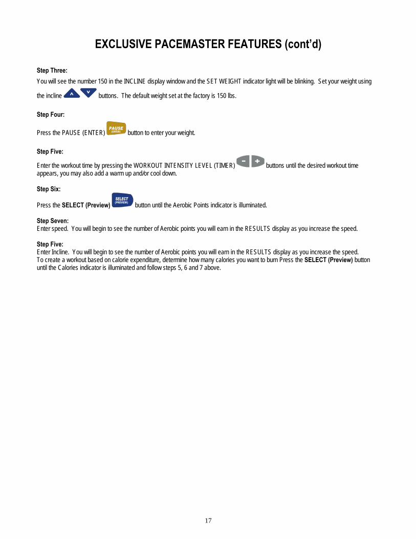
EXCLUSIVE PACEMASTER FEATURES (cont’d) Step Three: You will see the number 150 in the INCLINE display window and the SET WEIGHT indicator light will be blinking. Set your weight using
the incline buttons. The default weight set at the factory is 150 lbs. Step Four:
Press the PAUSE (ENTER) (ENTER) button to enter your weight. Step Five:
Enter the workout time by pressing the WORKOUT INTENSITY LEVEL (TIMER) buttons until the desired workout time appears, you may also add a warm up and/or cool down. Step Six:
Press the SELECT (Preview) (PREVIEW) button until the Aerobic Points indicator is illuminated. Step Seven: Enter speed. You will begin to see the number of Aerobic points you will earn in the RESULTS display as you increase the speed. Step Five: Enter Incline. You will begin to see the number of Aerobic points you will earn in the RESULTS display as you increase the speed. To create a workout based on calorie expenditure, determine how many calories you want to burn Press the SELECT (Preview) button until the Calories indicator is illuminated and follow steps 5, 6 and 7 above.

18
Care and Maintenance
The following section describes necessary maintenance for your PaceMaster treadmill. This maintenance is the responsibility of the purchaser and is not covered under our warranty. Failure to perform this necessary maintenance could result in damage to your treadmill.
CAUTION: Unplug your treadmill before attempting any cleaning or maintenance. Deck and Tread Belt Cleaning The running belt on your PaceMaster rides on a low friction, maintenance-free deck. Proper operation will be jeopardized if any water, dirt, solvents, fluids or abrasive materials come between the tread belt and the deck. For this reason, extra care must be used in keeping the belt clean. Use a soft, damp cloth to remove dust, dirt and other substances from the area between the belt and the side of the machine. Do not clean the tread belt by turning on the treadmill. Lubrication The motor and roller bearings are sealed for maintenance free operation and require no lubrication. The deck and tread belt are lubricated at the factory and are also maintenance free. Any attempt to lubricate underneath the running belt could result in damage. The side rails are made of steel. By occasionally applying a coat of automotive wax to them will help prevent rusting. Centering the Tread Belt To improve belt life, the belt should be reasonably centered. To center the belt, walk on the treadmill at 2.5 mph for a few minutes. Determine whether the belt drifts too far to the left or right side. If adjustments are required, stop the treadmill and follow the steps listed below. Never make adjustments while the tread belt is moving. TIP: If the tread belt is reasonably centered (no closer than 1/8” to the left or right deck shroud) no adjustments are necessary. Unnecessary adjustments can result in premature belt wear.
CAUTION: Unplug your treadmill before attempting any cleaning or maintenance. Step One: (figure 6) If the belt is drifting to the left, using a 3/16” Allen wrench, turn the left-hand adjustment bolt (3) a quarter turn clockwise and the right-hand adjustment bolt (4) a quarter turn counter-clockwise. If the belt is drifting to the right, using a 3/16” Allen wrench, turn the right-hand adjustment bolt (4) a quarter turn clockwise and the left-hand adjustment bolt (3) a quarter turn counter-clockwise. Step Two: Walk on the belt for 1 minute, observing belt tracking. If the belt moves to one side, repeat step 1.
Figure 6
19
TROUBLESHOOTING
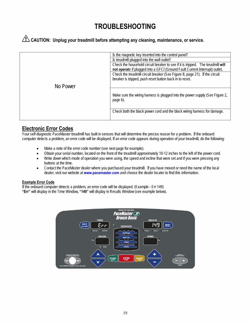
CAUTION: Unplug your treadmill before attempting any cleaning, maintenance, or service.
Is the magnetic key inserted into the control panel? Is treadmill plugged into the wall outlet? Check the household circuit breaker to see if it is tripped. The treadmill will not operate if plugged into a GFCI (Ground Fault Current Interrupt) outlet. Check the treadmill circuit breaker (See Figure 8, page 21). If the circuit breaker is tripped, push reset button back in to reset. Make sure the wiring harness is plugged into the power supply (See Figure 2, page 6).
No Power
Check both the black power cord and the black wiring harness for damage.
Electronic Error Codes Your self-diagnostic PaceMaster treadmill has built in sensors that will determine the precise reason for a problem. If the onboard computer detects a problem, an error code will be displayed. If an error code appears during operation of your treadmill, do the following:
• Make a note of the error code number (see next page for example). • Obtain your serial number, located on the front of the treadmill approximately 10-12 inches to the left of the power cord. • Write down which mode of operation you were using, the speed and incline that were set and if you were pressing any
buttons at the time. • Contact the PaceMaster dealer where you purchased your treadmill. If you have moved or need the name of the local
dealer, visit our website at www.pacemaster.com and choose the dealer locater to find this information. Example Error Code If the onboard computer detects a problem, an error code will be displayed. (Example - Err 149) “Err” will display in the Time Window, “149” will display in Results Window (see example below).
Err 149

20
TROUBLESHOOTING (cont’d)
CAUTION: Unplug your treadmill before attempting any cleaning, maintenance, or service. Error Code 133 or 134 This is a communication error that could be a result of the black wire harness not being plugged in all the way. Unplug the treadmill from the wall outlet and reconnect the black wire harness that you plugged in during Step Two of assembly, see page 6. Error Code 149 Error code 149 indicates a button was pressed when the magnetic key was inserted into the control panel. Do not press down on any button when inserting the magnetic key. Make sure any accessories that are mounted to the control panel (book rack, etc.) are not making contact with the membrane. Error Code 298 Error Code 298 is an RPM signal code - indicates a loss of the RPM signal during a workout. Check all wiring connections (optical sensor and wiring harness) and all wiring for cuts or damage. (See Figure 2 page 6). Error Code 307 Indicates that there was no speed sensor signal at start up. Check the speed sensor connection and wiring. Error Code 425 After start is pressed, the tread belt does not move and then “Err 425” appears. To reset this error code you must unplug the treadmill from the wall outlet for 10 seconds, and then check the items listed below. Check the drive motor wire connection to the power supply. Check the ceramic fuse (20 Amp – 250 V) on the power supply. Elevation Error Codes “Err” in the Incline Display - indicates a problem with the elevation system. Note: The treadmill will still function with the “Err” displayed in the incline Display, but the elevation system will not function. To determine the exact error code follow the procedure below. Insert the magnetic key, For the purpose of this test, DO NOT stand on the tread belt If “Err” appears in the incline display after pressing the Start/Quick, Stop/Reset, or Pause/Enter button, the control panel is not receiving an elevation reading. Start the treadmill and press the Up or Down Incline button, an “E 219” will appear in the Results Display. Check the both wiring connections between the elevation motor and the power supply. Also, check the wiring harness for cuts or visual damage. If “Err” appears in the incline display after attempting an elevation change, the control panel did not see elevation movement. Touch the incline Up or Down button and an “E 217” will appear in the Data Window. Check the wiring connection between the elevation motor and the power supply. Check the elevation fuse to see if it has blown. If the fuse has blown, replace fuse.
Err
e217

21
Figure 7
TROUBLESHOOTING (cont’d) Noises A Clicking, Rubbing or Grinding noise is present while the tread belt is moving. Remove all items from the cup holders on either side of the display Visually confirm that NO foreign objects (children’s toys, pet’s toys, etc…) are underneath, on top of, or against the treadmill. With the tread belt stopped visually check to see if the tread belt is reasonable centered, if it is not please refer to “centering the tread belt” under the maintenance section of this manual. Hesitation of the Tread belt Hesitation of the tread belt usually indicates slippage of either the tread belt (the belt you walk on) or the drive belt (the belt connecting the drive roller to the motor). To determine which of these belts is slipping, first adjust the drive belt tension and test to see if the slippage stops. If the hesitation is not corrected than the tread belt tension needs adjustment.
CAUTION: Unplug your treadmill before attempting any cleaning or maintenance. Drive Belt Tension Adjustment Step One: Use a Phillips head screwdriver to remove the 2 screws that hold the front of the motor cover in place and remove the motor cover. Step Two: (figure 7) Locate the four motor mount screws (item 1 in fig 7) as shown in the diagram and loosen them each two turns each using the 3/16" allen wrench. Continued on the following page
1
22
Figure 8
Figure 9
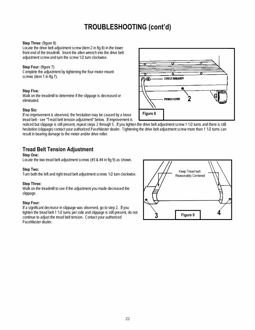
TROUBLESHOOTING (cont’d) Step Three: (figure 8) Locate the drive belt adjustment screw (item 2 in fig 8) in the lower front end of the treadmill. Insert the allen wrench into the drive belt adjustment screw and turn the screw 1/2 turn clockwise. Step Four: (figure 7) Complete the adjustment by tightening the four motor mount screws (item 1 in fig 7). Step Five: Walk on the treadmill to determine if the slippage is decreased or eliminated. Step Six: If no improvement is observed, the hesitation may be caused by a loose tread belt - see "Tread belt tension adjustment" below. If improvement is noticed but slippage is still present, repeat steps 2 through 5. If you tighten the drive belt adjustment screw 1 1/2 turns and there is still hesitation (slippage) contact your authorized PaceMaster dealer. Tightening the drive belt adjustment screw more than 1 1/2 turns can result in bearing damage to the motor and/or drive roller. Tread Belt Tension Adjustment Step One: Locate the two tread belt adjustment screws (#3 & #4 in fig 9) as shown. Step Two: Turn both the left and right tread belt adjustment screws 1/2 turn clockwise. Step Three: Walk on the treadmill to see if the adjustment you made decreased the slippage. Step Four: If a significant decrease in slippage was observed, go to step 2. If you tighten the tread belt 1 1/2 turns per side and slippage is still present, do not continue to adjust the tread belt tension. Contact your authorized PaceMaster dealer.

23
FREQUENTLY ASKED QUESTIONS Q. Why is time displayed as a negative number (i.e. – 1:15)?
A. The treadmill’s computer displays time in minutes and seconds (MM:SS) for workout times less than 1 Hour, and in hours and minutes (– H:MM) for workout times 1 hour or greater. – 1:15 represents one hour and 15 minutes.
Q. Why can’t I change the speed in warm up or cool down?
A. Warm up and cool down speeds are based on parameters recommended by the American College of Sports Medicine and cannot be overridden. To avoid undue cardiovascular stress, warm up begins at a lower percentage of the workout’s starting speed and gradually takes you to the workouts starting speed. Conversely, cool down gradually reduces speed based on a percentage of the workouts ending speed.
Q. How do I find out the total hours and miles on my treadmill?
A. Insert the magnetic safety key, when the “set weight” indicator begins to flash, press and hold the WORKOUT INTENSITY LEVEL + button the total time and mileage will appear in their respective windows and the power supply software version will appear in the INCLINE
Q. Can I eliminate warm up and/or cool down from a Variable Intensity Workout?
A. Yes. If you wish to remove the warm up and/or cool down phases prior to starting your workout, press the WARM UP/COOL DOWN button until the corresponding indicator light is no longer illuminated. While in the warm up mode, press the Warm Up / Cool Down button and you will advance into the main phase of your workout. While in the main workout mode press the Warm Up / Cool Down button to advance to the cool down
Q. Why is dust accumulating behind and/or underneath my treadmill?
A. This is normal. The dust is a combination of the PVC belt material and the phenolic deck surface as it wears.
24
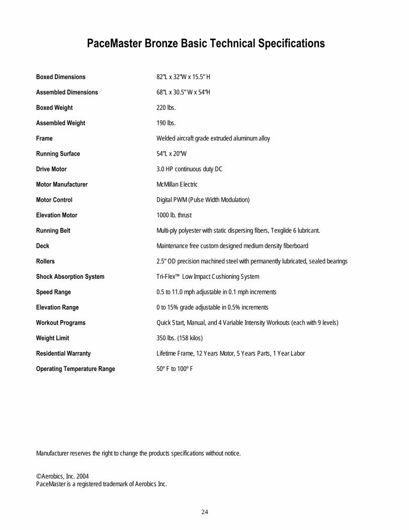
PaceMaster Bronze Basic Technical Specifications Boxed Dimensions 82”L x 32”W x 15.5” H Assembled Dimensions 68”L x 30.5” W x 54”H Boxed Weight 220 lbs. Assembled Weight 190 lbs. Frame Welded aircraft grade extruded aluminum alloy Running Surface 54”L x 20”W Drive Motor 3.0 HP continuous duty DC Motor Manufacturer McMillan Electric Motor Control Digital PWM (Pulse Width Modulation) Elevation Motor 1000 lb. thrust Running Belt Multi-ply polyester with static dispersing fibers, Texglide 6 lubricant.
Deck Maintenance free custom designed medium density fiberboard
Rollers 2.5” OD precision machined steel with permanently lubricated, sealed bearings
Shock Absorption System Tri-Flex™ Low Impact Cushioning System Speed Range 0.5 to 11.0 mph adjustable in 0.1 mph increments
Elevation Range 0 to 15% grade adjustable in 0.5% increments Workout Programs Quick Start, Manual, and 4 Variable Intensity Workouts (each with 9 levels) Weight Limit 350 lbs. (158 kilos) Residential Warranty Lifetime Frame, 12 Years Motor, 5 Years Parts, 1 Year Labor Operating Temperature Range 50º F to 100º F Manufacturer reserves the right to change the products specifications without notice. © Aerobics, Inc. 2004 PaceMaster is a registered trademark of Aerobics Inc.