Embed Size (px)
Citation preview

OWNER’S MANUAL AND SERVICE GUIDE
INDUSTRIAL ELECTRIC VEHICLE
SC NXG and SCT NXG Series
January 2018
Vehicle shown with optional equipment.

iii
IntroductionThank you for choosing a Pack Mule Industrial Electric Vehicle, proudly built in the USA by Wesley Interna-
tional. Wesley International is committed to providing you with the best quality product and backing it with exceptional customer service. This owner’s manual provided to help you get the most out of your new vehi-cle for many years to come. For convenience, record your product information in the space below and keep this information with the vehicle. The model and serial numbers can be found on the vehicle identification plate attached to the side of the motor compartment. See page 5 for the location of the vehicle identification plate.
Register Your Pack Mule
Registration is easy. Just go to http://www.packmule.com/mule-owners/register-a-mule/, complete the online form, and click submit.
If You Need HelpYou will find many answers in this manual or online at www.packmule.com. If you don’t find what you need,
just email us at [email protected] or call (800) 241-2869 or (404) 292-7441. We’re always glad to help.
Record Your Product Information
Model #:
Serial #:
Purchase Date:
Important
Product registration is required for warranty coverage.
Wesley International3680 Chestnut Street
Scottdale, GA 30079
Phone (404) 292-7441 • Toll Free (800) 241-2869 • Fax (404) 292-8469
[email protected] • www.wesleyinternational.com

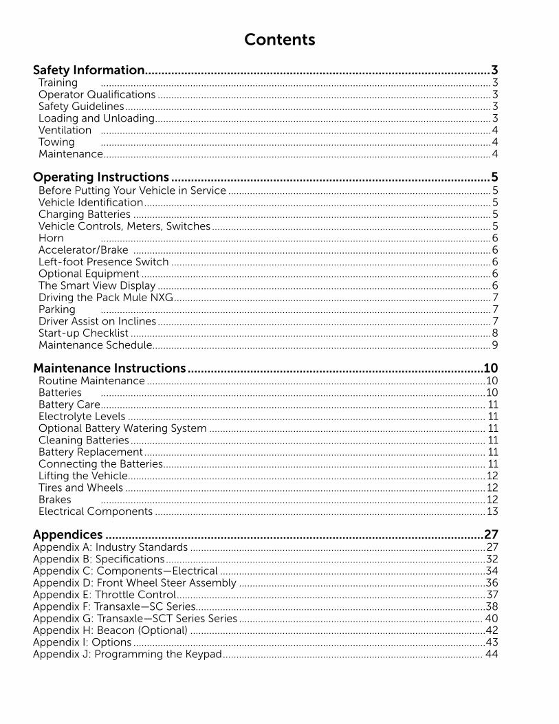
Contents
Safety Information.........................................................................................................3Training ................................................................................................................................................3Operator Qualifications ...........................................................................................................................3Safety Guidelines .......................................................................................................................................3Loading and Unloading ............................................................................................................................3Ventilation ................................................................................................................................................4Towing ................................................................................................................................................4Maintenance ...............................................................................................................................................4
Operating Instructions .................................................................................................5 Before Putting Your Vehicle in Service .................................................................................................5Vehicle Identification ................................................................................................................................5Charging Batteries ....................................................................................................................................5Vehicle Controls, Meters, Switches .......................................................................................................5Horn ................................................................................................................................................6Accelerator/Brake ....................................................................................................................................6Left-foot Presence Switch ......................................................................................................................6Optional Equipment .................................................................................................................................6The Smart View Display ...........................................................................................................................6Driving the Pack Mule NXG ..................................................................................................................... 7Parking ................................................................................................................................................ 7Driver Assist on Inclines ........................................................................................................................... 7Start-up Checklist .....................................................................................................................................8Maintenance Schedule.............................................................................................................................9
Maintenance Instructions ..........................................................................................10Routine Maintenance .............................................................................................................................10Batteries ..............................................................................................................................................10Battery Care .............................................................................................................................................. 11Electrolyte Levels .................................................................................................................................... 11Optional Battery Watering System ...................................................................................................... 11Cleaning Batteries ................................................................................................................................... 11Battery Replacement .............................................................................................................................. 11Connecting the Batteries ....................................................................................................................... 11Lifting the Vehicle.................................................................................................................................... 12Tires and Wheels ..................................................................................................................................... 12Brakes .............................................................................................................................................. 12Electrical Components .......................................................................................................................... 13
Appendices ...................................................................................................................27Appendix A: Industry Standards .............................................................................................................27Appendix B: Specifications ......................................................................................................................32Appendix C: Components—Electrical ..................................................................................................34Appendix D: Front Wheel Steer Assembly ...........................................................................................36Appendix E: Throttle Control ..................................................................................................................37Appendix F: Transaxle—SC Series...........................................................................................................38Appendix G: Transaxle—SCT Series Series .......................................................................................... 40Appendix H: Beacon (Optional) .............................................................................................................42Appendix I: Options ..................................................................................................................................43Appendix J: Programming the Keypad ................................................................................................ 44

1
Please read this first:
When you receive your PackMule NXG stock chaser, it’s important to visually inspect the machine for any damage that may have occurred during shipping. If you find any shipping damage, have it noted on the car-rier’s bill immediately, specifically identifying the nature of the damage.
Keep this manual with the vehicle at all times. It provides operating and maintenance instructions, as well as precautions for the safe operation of the vehicle. It is the responsibility of the owner, user, lessor or lessees to ensure that the vehicle is used as intended.
Please read this entire manual to familiarize yourself with the safe operation of this vehicle, paying particular attention to anything labeled Caution, Note, or Warning. See below for the graphic representation of these. We also encourage you to read the industry standard operating and safety procedures in Appendix A.
Because of continuing product improvement, changes or updates may be made to this manual, making it subject to change without notice. For the most up-to-date version of the manual, go to the PackMule web-site (http://www.packmule.com/support/product-manuals) or call Wesley International at 1-800-241-2869.
The Pack Mule Division of Wesley International reserves the right to incorporate engineering and design changes to products in this manual without any obligation to include these changes on any units or vehicles already purchased or leased.
The Pack Mule Division and/or Wesley International accepts no liability in connection with any errors or omissions in this manual and specifically disclaims any liability for any incidental and consequential damages arising from the use of information in this manual.
The use of non-OEM (Original Equipment Manufacturer) parts may void the warranty.
Overfilling the batteries may void the warranties.
Notes, Cautions, and WarningsThroughout this manual important information will be emphasized under one of the following headings.
Please pay special attention to this information.
This graphic indicates information regarding a condition that should be ob-served.
This graphic indicates information regarding a condition that might result in damage to the vehicle.
This graphic indicates information regarding a condition that might result in severe injury or death.
2
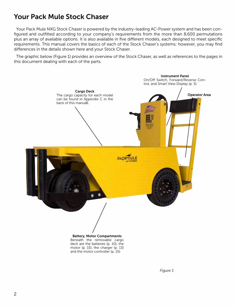
Your Pack Mule Stock Chaser
Your Pack Mule NXG Stock Chaser is powered by the industry-leading AC-Power system and has been con-figured and outfitted according to your company’s requirements from the more than 8,600 permutations plus an array of available options. It is also available in five different models, each designed to meet specific requirements. This manual covers the basics of each of the Stock Chaser’s systems; however, you may find differences in the details shown here and your Stock Chaser.
The graphic below (Figure 1) provides an overview of the Stock Chaser, as well as references to the pages in this document dealing with each of the parts.
Operator AreaCargo Deck
The cargo capacity for each model can be found in Appendix C in the back of this manual.
Instrument PanelOn/Off Switch, Forward/Reverse Con-trol, and Smart View Display (p. 5)
Battery, Motor CompartmentsBeneath the removable cargo deck are the batteries (p. 10), the motor (p. 15), the charger (p. 13) and the motor controller (p. 15).
Figure 1
3
Safety Information
This manual has been designed to help the owner/operator operate the vehicle safely and according to the procedures and standards for which the vehicle was designed and intended for use. This section pro-vides the essentials of safe operation. There is a more thorough discussion in Appendix A: Industry Stan-dards.
TrainingVehicle owners are responsible for making certain
that appropriate personnel are fully trained in the safe operation of the Stock Chaser and understand the vehicle’s characteristics and features, the operation of its controls, and safe driving practices. Those re-sponsible for training operators should first become familiar with the conditions of the place where the vehicle will be operated in order to assess its effect on safe operation. Training should occur under the conditions of the operating environment while ad-hering to the safety guidelines and should include:
• Safety guidelines• Safely operating vehicle in the work environ-
ment. • Operation of all controls• Safe driving practices• A driving and operating test
Operator QualificationsOperators should be selected based on their ability
to safely operate the vehicle, including vision, hear-ing, physical and mental capabilities. Operators must:
• Demonstrate a working knowledge of all con-trols
• Understand all safety guidelines• Be able to properly drive and park the vehicle un-
der usual working conditions• Know how to properly load, unload and tow car-
go• Recognize maintenance problems
Safety GuidelinesAll Pack Mule vehicles are designed for use on
smooth surfaces in and around industrial plants, warehouses, nurseries and greenhouses. They are not intended for use outdoors, up and down steep grades, or on public roads and highways.
Follow these guidelines for safe vehicle operation:
• Read this manual before operating the vehicle• Read, understand and observe all labels affixed to
the vehicle• Do not operate vehicle without first checking the
brakes • Do not mount or dismount the vehicle when the
key is in the ON position• Do not drive the vehicle if the accelerator re-
quires excessive pressure• Do not park or operate the vehicle near flamma-
ble objects or in a flammable or hazardous envi-ronment
• Use only necessary power• Keep both hands on the steering control while
operating the vehicle• Accelerate and decelerate slowly and in a con-
trolled manner• Always reduce speed when operating on poor
terrain or in poor conditions• Always maintain adequate distance between the
vehicles, and people and obstacles• Do not use the vehicle to push objects• Do not allow the tires to lose contact with the
ground• Proceed around low overhangs with caution. Be
sure there is enough clearance for the operator’s head and the highest point of the vehicle or any attached accessories.
• Never abruptly change direction • Always drive directly up an incline; never across• Never exceed the designated load or towing ca-
pacityOn grades, it is possible for vehicles to coast at
greater than normal speeds. To prevent loss of vehi-cle control and possible serious injury, speeds should be limited to no more than maximum speed on level ground.
Good common sense and prudent driving practic-es do more to prevent accidents and injuries than all of the warnings and instructions combined. Wesley International strongly suggests that the owner-oper-ator read this entire manual paying particular atten-tion to the CAUTIONS, SAFETY INFORMATION, and WARNINGS.
Wesley International LLC reserves the right to make design changes without obligation to make these changes on units previously sold, and the informa-tion contained in this manual is subject to change without notice.
Loading and UnloadingFollow these guidelines when loading and unload-
ing cargo:
• Turn the vehicle off while loading or unloading• Do not exceed the maximum cargo capacity
4
• Carefully and evenly position all loads• Secure cargo so that nothing can easily fall off of
the vehicle• Be extremely careful when carrying loads that
extend beyond the vehicle’s deck
TowingFollow these guidelines when towing:
• Turn the vehicle off and place directional selector in the center (neutral) position before attaching load to hitch.
• Ensure hitch is properly installed and secured (If your Stock Chaser does not have a factory-in-stalled hitch, the hitch is available from Wesley International.)
• Do not exceed the maximum towing capacity (The model’s towing capacity is on the Vehicle Identification plate (Figure 2) and in Appendix C of this manual.)
• Do not exceed 5 mph when towing• Take extreme care when towing down an in-
cline• Avoid sudden stops since the stop may cause the
trailer to jackknife• Keep in mind that heavy loads being towed may
significantly increase stopping distances
MaintenanceAlways maintain your vehicle in accordance with
the service schedule in this manual and keep com-plete records of the maintenance history of the vehi-cle. Ensure that maintenance personnel performing any service or repair work on the vehicle are properly trained and qualified. When performing any mainte-nance on the vehicle, disable the vehicle by removing the key from the key switch and disconnecting the battery cable.
Untrained or unauthorized personnel should nev-er attempt to perform service or maintenance on the vehicle. Improper maintenance can cause haz-ardous conditions. Contact Wesley International for authorized service assistance.
Be sure to check the polarity of each battery terminal and rewire the batteries according to the schematic shown in this manual (p. 11, Figure 14). Never install a wire instead of a proper fuse, even for a temporary fix. It may cause extensive damage and possible fire. Do not use a screwdriver or other metal object to remove fuses. Doing so may cause an electrical short and damage the system. Do not modify or tamper with any part of the operating or speed control sys-tems. All inspections and adjustments must be made by a qualified technician.
Use a dedicated circuit for each battery charger and do not plug other appliances into recepticles on the circuit while the batteries are charging.
Always use insulated tools when working in the battery area. Improper tools may cause sparks or an explosion. Wear approved safety goggles or face shield.
The electrolyte in a lead acid battery is an acid solution which can cause severe burns to the body and eyes. Treat all spills to the body and eyes with extended flushing with clear water; then contact a physician immediately.
Electrolyte spills will corrode the vehicles’s frame and body if not treated immediately. Wear proper protective clothing, gloves and eye wear. Thor-oughly clean all areas with a neutralizing solution of ¼-cup (60 mL) sodium bicarbonate (baking soda) dissolved in 1½ gallons (6 L) of water.
Always secure and support the vehicle using wheel chocks and safety stands. Never get under a vehicle that is supported by a jack. Lift the vehicle in accor-dance with the instructions in this manual (p. 12).
Always test drive the vehicle after any repairs or maintenance in a safe area free of any other vehicles or pedestrians.
Wesley recommends that only OEM replacement parts be used. Using any parts other than those ap-proved by Wesley may void the warranty.
VentilationWhen performing any maintenance on the Pack
Mule Stock Chaser or charging the batteries, make sure that you are in a well-ventilated area. Hydrogen gas is generated in the charging cycle and is explo-sive in concentrations as low as 4%. Five air exchang-es per hour is considered the minimum ventilation required.
The battery charging cycle may generate high-ly explosive hydrogen gas. Make certain that the charging is done in a well ventilated area and is away from anything that might create sparks.
5
Operating Instructions
Before Putting Your Vehicle in Service• Check for leaking fluids (brake fluid, battery acid,
or transaxle oil).• Check condition of tires for defects or damage.
If your vehicle is equipped with pneumatic tires, make certain that they are properly inflated.
• Check to ensure that wheel lugs are tight.• Check to ensure that battery cables are tight and
batteries are secure.• Check the steering, brake, and electrical controls
for proper operation.• Charge the batteries.
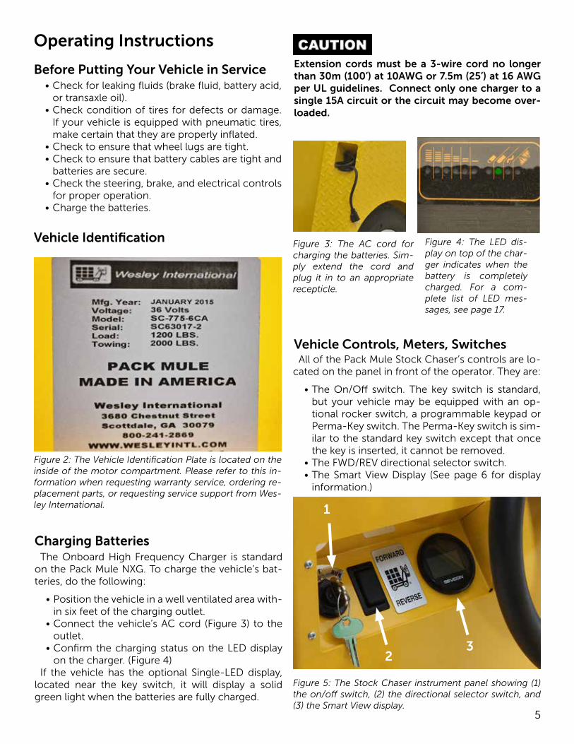
Vehicle Identification
Figure 2: The Vehicle Identification Plate is located on the inside of the motor compartment. Please refer to this in-formation when requesting warranty service, ordering re-placement parts, or requesting service support from Wes-ley International.
Charging BatteriesThe Onboard High Frequency Charger is standard
on the Pack Mule NXG. To charge the vehicle’s bat-teries, do the following:
• Position the vehicle in a well ventilated area with-in six feet of the charging outlet.
• Connect the vehicle’s AC cord (Figure 3) to the outlet.
• Confirm the charging status on the LED display on the charger. (Figure 4)
If the vehicle has the optional Single-LED display, located near the key switch, it will display a solid green light when the batteries are fully charged.
Extension cords must be a 3-wire cord no longer than 30m (100’) at 10AWG or 7.5m (25’) at 16 AWG per UL guidelines. Connect only one charger to a single 15A circuit or the circuit may become over-loaded.
Figure 3: The AC cord for charging the batteries. Sim-ply extend the cord and plug it in to an appropriate recepticle.
Figure 4: The LED dis-play on top of the char-ger indicates when the battery is completely charged. For a com-plete list of LED mes-sages, see page 17.
Vehicle Controls, Meters, SwitchesAll of the Pack Mule Stock Chaser’s controls are lo-
cated on the panel in front of the operator. They are:
• The On/Off switch. The key switch is standard, but your vehicle may be equipped with an op-tional rocker switch, a programmable keypad or Perma-Key switch. The Perma-Key switch is sim-ilar to the standard key switch except that once the key is inserted, it cannot be removed.
• The FWD/REV directional selector switch. • The Smart View Display (See page 6 for display
information.)
Figure 5: The Stock Chaser instrument panel showing (1) the on/off switch, (2) the directional selector switch, and (3) the Smart View display.
1
23
6
Left-foot Presence SwitchThe left-foot presence switch ensures that the op-
erator has both legs in the vehicle before the vehicle is put into motion. To move the vehicle either forward or backward, the operator must depress the switch. When the switch is released, the vehicle stops.
Optional EquipmentYour Pack Mule NXG Stock Chaser may be equipped
with any of the following optional equipment:
Headlights/Tail Lights: These are controlled by a rocker switch located near the directional control.
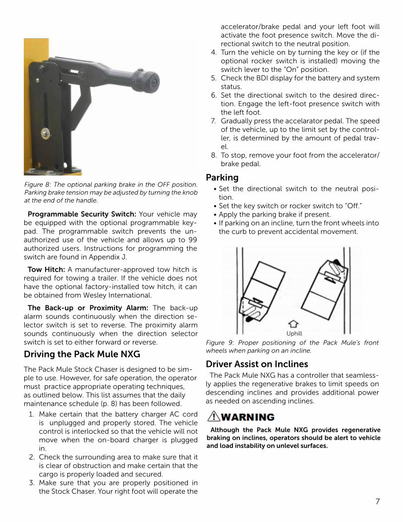
Parking Brake: Engaging the parking brake will prevent the motor from operating until the brake is released. The tension on the parking brake can be adjusted by turning the knob at the end of the han-dle. Turn the knob clockwise to increase the tension and counterclockwise to decrease it. Some models require that you release the lock screw to adjust ten-sion.Horn
The horn, located on the left side of the panel, sounds when you press the horn button. It will not sound when the key switch is in the “off” position.
Accelerator/Brake
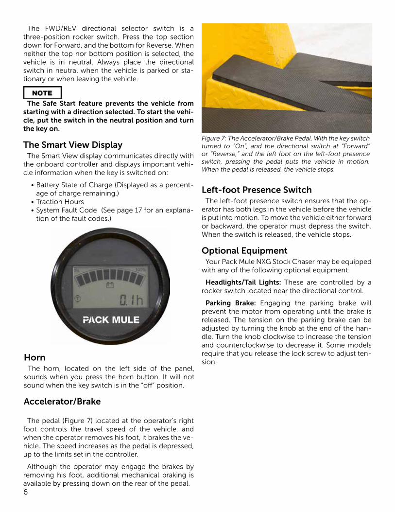
The pedal (Figure 7) located at the operator’s right foot controls the travel speed of the vehicle, and when the operator removes his foot, it brakes the ve-hicle. The speed increases as the pedal is depressed, up to the limits set in the controller.
Although the operator may engage the brakes by removing his foot, additional mechanical braking is available by pressing down on the rear of the pedal.
Figure 7: The Accelerator/Brake Pedal. With the key switch turned to “On”, and the directional switch at “Forward” or “Reverse,” and the left foot on the left-foot presence switch, pressing the pedal puts the vehicle in motion. When the pedal is released, the vehicle stops.
The FWD/REV directional selector switch is a three-position rocker switch. Press the top section down for Forward, and the bottom for Reverse. When neither the top nor bottom position is selected, the vehicle is in neutral. Always place the directional switch in neutral when the vehicle is parked or sta-tionary or when leaving the vehicle.
The Safe Start feature prevents the vehicle from starting with a direction selected. To start the vehi-cle, put the switch in the neutral position and turn the key on.
The Smart View DisplayThe Smart View display communicates directly with
the onboard controller and displays important vehi-cle information when the key is switched on:
• Battery State of Charge (Displayed as a percent-age of charge remaining.)
• Traction Hours • System Fault Code (See page 17 for an explana-
tion of the fault codes.)
7
Figure 8: The optional parking brake in the OFF position. Parking brake tension may be adjusted by turning the knob at the end of the handle.
Programmable Security Switch: Your vehicle may be equipped with the optional programmable key-pad. The programmable switch prevents the un-authorized use of the vehicle and allows up to 99 authorized users. Instructions for programming the switch are found in Appendix J.
Tow Hitch: A manufacturer-approved tow hitch is required for towing a trailer. If the vehicle does not have the optional factory-installed tow hitch, it can be obtained from Wesley International.
The Back-up or Proximity Alarm: The back-up alarm sounds continuously when the direction se-lector switch is set to reverse. The proximity alarm sounds continuously when the direction selector switch is set to either forward or reverse.
accelerator/brake pedal and your left foot will activate the foot presence switch. Move the di-rectional switch to the neutral position.
4. Turn the vehicle on by turning the key or (if the optional rocker switch is installed) moving the switch lever to the “On” position.
5. Check the BDI display for the battery and system status.
6. Set the directional switch to the desired direc-tion. Engage the left-foot presence switch with the left foot.
7. Gradually press the accelarator pedal. The speed of the vehicle, up to the limit set by the control-ler, is determined by the amount of pedal trav-el.
8. To stop, remove your foot from the accelerator/brake pedal.
Driving the Pack Mule NXG
The Pack Mule Stock Chaser is designed to be sim-ple to use. However, for safe operation, the operator must practice appropriate operating techniques, as outlined below. This list assumes that the daily maintenance schedule (p. 8) has been followed.
1. Make certain that the battery charger AC cord is unplugged and properly stored. The vehicle control is interlocked so that the vehicle will not move when the on-board charger is plugged in.
2. Check the surrounding area to make sure that it is clear of obstruction and make certain that the cargo is properly loaded and secured.
3. Make sure that you are properly positioned in the Stock Chaser. Your right foot will operate the
Parking• Set the directional switch to the neutral posi-
tion.• Set the key switch or rocker switch to “Off.”• Apply the parking brake if present.• If parking on an incline, turn the front wheels into
the curb to prevent accidental movement.
Figure 9: Proper positioning of the Pack Mule’s front wheels when parking on an incline.
Driver Assist on InclinesThe Pack Mule NXG has a controller that seamless-
ly applies the regenerative brakes to limit speeds on descending inclines and provides additional power as needed on ascending inclines.
Although the Pack Mule NXG provides regenerative braking on inclines, operators should be alert to vehicle and load instability on unlevel surfaces.
Uphill
8
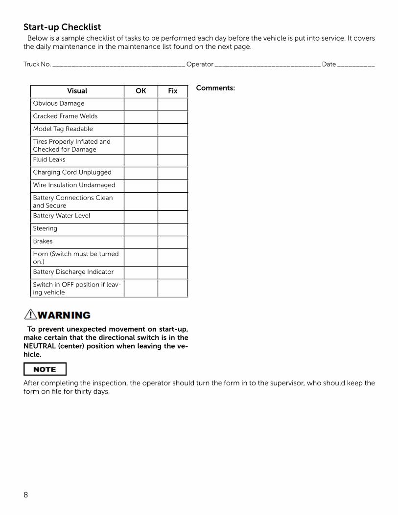
Start-up ChecklistBelow is a sample checklist of tasks to be performed each day before the vehicle is put into service. It covers
the daily maintenance in the maintenance list found on the next page.
Truck No. ___________________________________ Operator ____________________________ Date __________
Visual OK Fix
Obvious Damage
Cracked Frame Welds
Model Tag Readable
Tires Properly Inflated and Checked for Damage
Fluid Leaks
Charging Cord Unplugged
Wire Insulation Undamaged
Battery Connections Clean and Secure
Battery Water Level
Steering
Brakes
Horn (Switch must be turned on.)
Battery Discharge Indicator
Switch in OFF position if leav-ing vehicle
Comments:
To prevent unexpected movement on start-up, make certain that the directional switch is in the NEUTRAL (center) position when leaving the ve-hicle.
After completing the inspection, the operator should turn the form in to the supervisor, who should keep the form on file for thirty days.
9
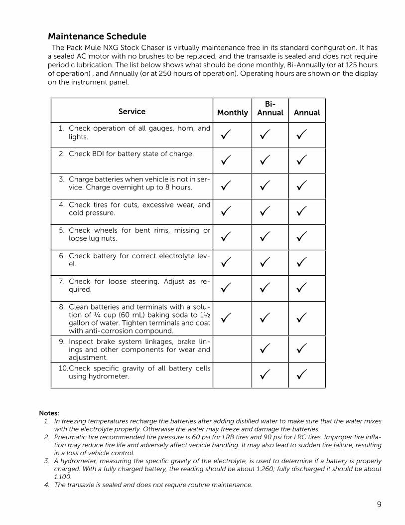
Service MonthlyBi-
Annual Annual
1. Check operation of all gauges, horn, and lights. P P P
2. Check BDI for battery state of charge.
P P P3. Charge batteries when vehicle is not in ser-
vice. Charge overnight up to 8 hours. P P P4. Check tires for cuts, excessive wear, and
cold pressure. P P P5. Check wheels for bent rims, missing or
loose lug nuts. P P P6. Check battery for correct electrolyte lev-
el. P P P7. Check for loose steering. Adjust as re-
quired. P P P8. Clean batteries and terminals with a solu-
tion of ¼ cup (60 mL) baking soda to 1½ gallon of water. Tighten terminals and coat with anti-corrosion compound.
P P P9. Inspect brake system linkages, brake lin-
ings and other components for wear and adjustment.
P P10. Check specific gravity of all battery cells
using hydrometer. P P
Notes:1. In freezing temperatures recharge the batteries after adding distilled water to make sure that the water mixes
with the electrolyte properly. Otherwise the water may freeze and damage the batteries.2. Pneumatic tire recommended tire pressure is 60 psi for LRB tires and 90 psi for LRC tires. Improper tire infla-
tion may reduce tire life and adversely affect vehicle handling. It may also lead to sudden tire failure, resulting in a loss of vehicle control.
3. A hydrometer, measuring the specific gravity of the electrolyte, is used to determine if a battery is properly charged. With a fully charged battery, the reading should be about 1.260; fully discharged it should be about 1.100.
4. The transaxle is sealed and does not require routine maintenance.
Maintenance ScheduleThe Pack Mule NXG Stock Chaser is virtually maintenance free in its standard configuration. It has
a sealed AC motor with no brushes to be replaced, and the transaxle is sealed and does not require periodic lubrication. The list below shows what should be done monthly, Bi-Annually (or at 125 hours of operation) , and Annually (or at 250 hours of operation). Operating hours are shown on the display on the instrument panel.
10
Maintenance Instructions
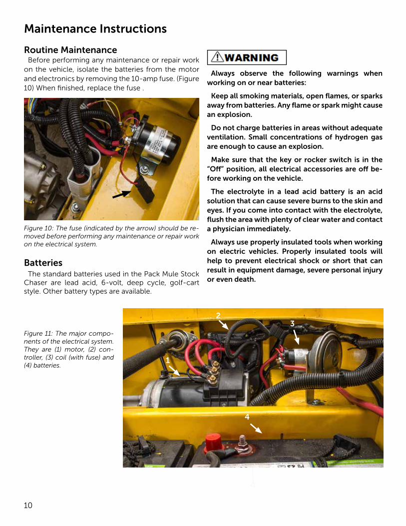
Routine MaintenanceBefore performing any maintenance or repair work
on the vehicle, isolate the batteries from the motor and electronics by removing the 10-amp fuse. (Figure 10) When finished, replace the fuse .
1
2
3
4
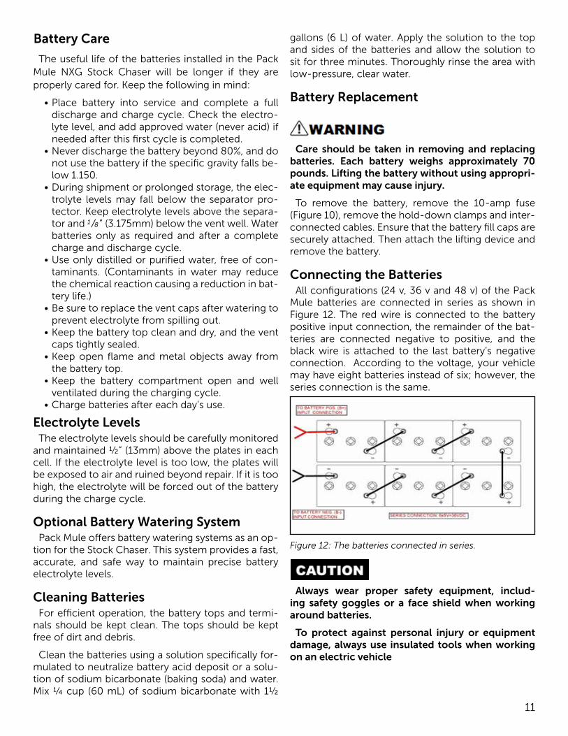
Figure 11: The major compo-nents of the electrical system. They are (1) motor, (2) con-troller, (3) coil (with fuse) and (4) batteries.
BatteriesThe standard batteries used in the Pack Mule Stock
Chaser are lead acid, 6-volt, deep cycle, golf-cart style. Other battery types are available.
5
Always observe the following warnings when working on or near batteries:
Keep all smoking materials, open flames, or sparks away from batteries. Any flame or spark might cause an explosion.
Do not charge batteries in areas without adequate ventilation. Small concentrations of hydrogen gas are enough to cause an explosion.
Make sure that the key or rocker switch is in the “Off” position, all electrical accessories are off be-fore working on the vehicle.
The electrolyte in a lead acid battery is an acid solution that can cause severe burns to the skin and eyes. If you come into contact with the electrolyte, flush the area with plenty of clear water and contact a physician immediately.
Always use properly insulated tools when working on electric vehicles. Properly insulated tools will help to prevent electrical shock or short that can result in equipment damage, severe personal injury or even death.
Figure 10: The fuse (indicated by the arrow) should be re-moved before performing any maintenance or repair work on the electrical system.
1
23
4
11
Battery Care
The useful life of the batteries installed in the Pack Mule NXG Stock Chaser will be longer if they are properly cared for. Keep the following in mind:
• Place battery into service and complete a full discharge and charge cycle. Check the electro-lyte level, and add approved water (never acid) if needed after this first cycle is completed.
• Never discharge the battery beyond 80%, and do not use the battery if the specific gravity falls be-low 1.150.
• During shipment or prolonged storage, the elec-trolyte levels may fall below the separator pro-tector. Keep electrolyte levels above the separa-tor and 1/8” (3.175mm) below the vent well. Water batteries only as required and after a complete charge and discharge cycle.
• Use only distilled or purified water, free of con-taminants. (Contaminants in water may reduce the chemical reaction causing a reduction in bat-tery life.)
• Be sure to replace the vent caps after watering to prevent electrolyte from spilling out.
• Keep the battery top clean and dry, and the vent caps tightly sealed.
• Keep open flame and metal objects away from the battery top.
• Keep the battery compartment open and well ventilated during the charging cycle.
• Charge batteries after each day’s use.
Electrolyte LevelsThe electrolyte levels should be carefully monitored
and maintained ½” (13mm) above the plates in each cell. If the electrolyte level is too low, the plates will be exposed to air and ruined beyond repair. If it is too high, the electrolyte will be forced out of the battery during the charge cycle.
Optional Battery Watering SystemPack Mule offers battery watering systems as an op-
tion for the Stock Chaser. This system provides a fast, accurate, and safe way to maintain precise battery electrolyte levels.
Cleaning BatteriesFor efficient operation, the battery tops and termi-
nals should be kept clean. The tops should be kept free of dirt and debris.
Clean the batteries using a solution specifically for-mulated to neutralize battery acid deposit or a solu-tion of sodium bicarbonate (baking soda) and water. Mix ¼ cup (60 mL) of sodium bicarbonate with 1½
gallons (6 L) of water. Apply the solution to the top and sides of the batteries and allow the solution to sit for three minutes. Thoroughly rinse the area with low-pressure, clear water.
Battery Replacement
Care should be taken in removing and replacing batteries. Each battery weighs approximately 70 pounds. Lifting the battery without using appropri-ate equipment may cause injury.
To remove the battery, remove the 10-amp fuse (Figure 10), remove the hold-down clamps and inter-connected cables. Ensure that the battery fill caps are securely attached. Then attach the lifting device and remove the battery.
Connecting the BatteriesAll configurations (24 v, 36 v and 48 v) of the Pack
Mule batteries are connected in series as shown in Figure 12. The red wire is connected to the battery positive input connection, the remainder of the bat-teries are connected negative to positive, and the black wire is attached to the last battery’s negative connection. According to the voltage, your vehicle may have eight batteries instead of six; however, the series connection is the same.
Figure 12: The batteries connected in series.
Always wear proper safety equipment, includ-ing safety goggles or a face shield when working around batteries.
To protect against personal injury or equipment damage, always use insulated tools when working on an electric vehicle
12
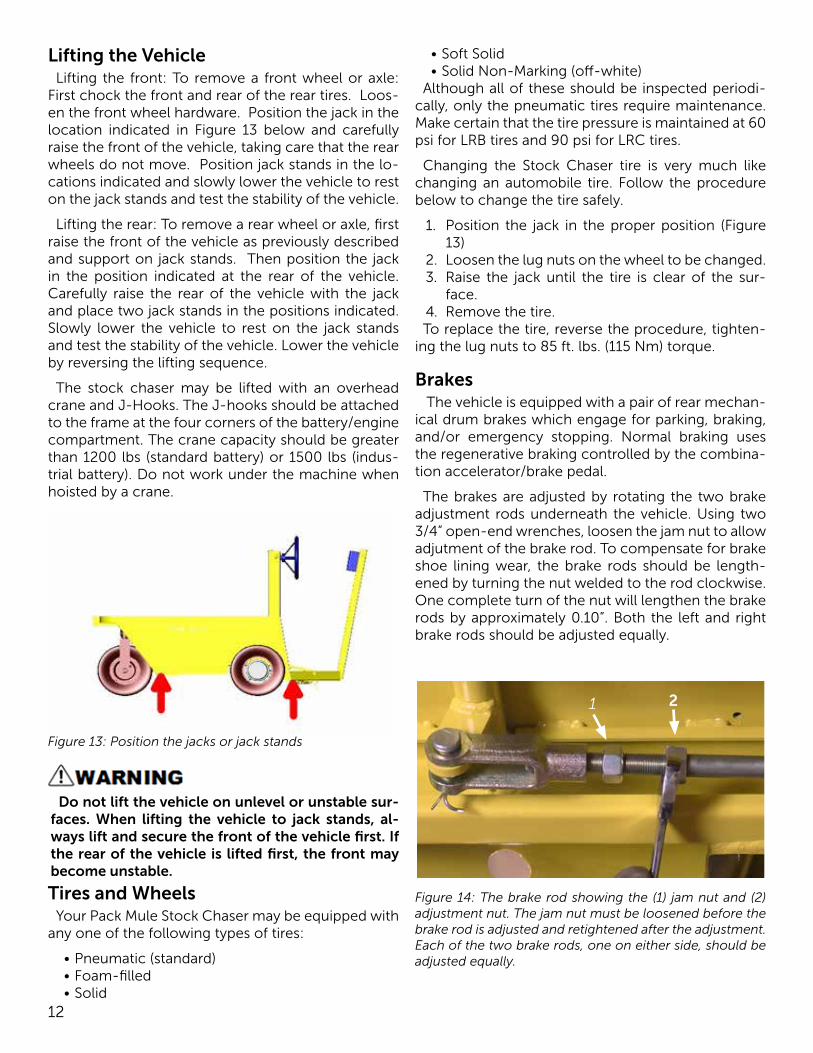
Lifting the VehicleLifting the front: To remove a front wheel or axle:
First chock the front and rear of the rear tires. Loos-en the front wheel hardware. Position the jack in the location indicated in Figure 13 below and carefully raise the front of the vehicle, taking care that the rear wheels do not move. Position jack stands in the lo-cations indicated and slowly lower the vehicle to rest on the jack stands and test the stability of the vehicle.
Lifting the rear: To remove a rear wheel or axle, first raise the front of the vehicle as previously described and support on jack stands. Then position the jack in the position indicated at the rear of the vehicle. Carefully raise the rear of the vehicle with the jack and place two jack stands in the positions indicated. Slowly lower the vehicle to rest on the jack stands and test the stability of the vehicle. Lower the vehicle by reversing the lifting sequence.
The stock chaser may be lifted with an overhead crane and J-Hooks. The J-hooks should be attached to the frame at the four corners of the battery/engine compartment. The crane capacity should be greater than 1200 lbs (standard battery) or 1500 lbs (indus-trial battery). Do not work under the machine when hoisted by a crane.
Figure 13: Position the jacks or jack stands
Do not lift the vehicle on unlevel or unstable sur-faces. When lifting the vehicle to jack stands, al-ways lift and secure the front of the vehicle first. If the rear of the vehicle is lifted first, the front may become unstable.
• Soft Solid• Solid Non-Marking (off-white)
Although all of these should be inspected periodi-cally, only the pneumatic tires require maintenance.Make certain that the tire pressure is maintained at 60 psi for LRB tires and 90 psi for LRC tires.
Changing the Stock Chaser tire is very much like changing an automobile tire. Follow the procedure below to change the tire safely.
1. Position the jack in the proper position (Figure 13)
2. Loosen the lug nuts on the wheel to be changed.3. Raise the jack until the tire is clear of the sur-
face.4. Remove the tire.To replace the tire, reverse the procedure, tighten-
ing the lug nuts to 85 ft. lbs. (115 Nm) torque.
Brakes The vehicle is equipped with a pair of rear mechan-
ical drum brakes which engage for parking, braking, and/or emergency stopping. Normal braking uses the regenerative braking controlled by the combina-tion accelerator/brake pedal.
The brakes are adjusted by rotating the two brake adjustment rods underneath the vehicle. Using two 3/4” open-end wrenches, loosen the jam nut to allow adjutment of the brake rod. To compensate for brake shoe lining wear, the brake rods should be length-ened by turning the nut welded to the rod clockwise. One complete turn of the nut will lengthen the brake rods by approximately 0.10”. Both the left and right brake rods should be adjusted equally.
Tires and WheelsYour Pack Mule Stock Chaser may be equipped with
any one of the following types of tires:
• Pneumatic (standard)• Foam-filled• Solid
Figure 14: The brake rod showing the (1) jam nut and (2) adjustment nut. The jam nut must be loosened before the brake rod is adjusted and retightened after the adjustment. Each of the two brake rods, one on either side, should be adjusted equally.
1 2
13
Electrical Components
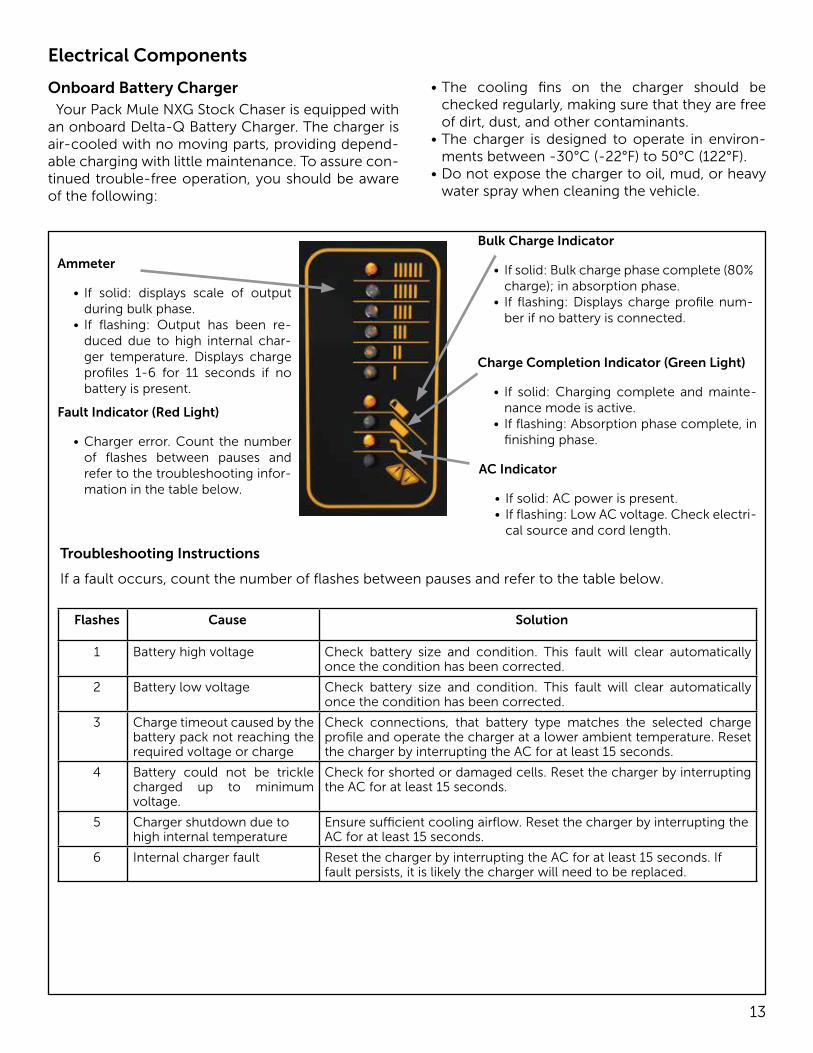
Onboard Battery ChargerYour Pack Mule NXG Stock Chaser is equipped with
an onboard Delta-Q Battery Charger. The charger is air-cooled with no moving parts, providing depend-able charging with little maintenance. To assure con-tinued trouble-free operation, you should be aware of the following:
• The cooling fins on the charger should be checked regularly, making sure that they are free of dirt, dust, and other contaminants.
• The charger is designed to operate in environ-ments between -30°C (-22°F) to 50°C (122°F).
• Do not expose the charger to oil, mud, or heavy water spray when cleaning the vehicle.
Flashes Cause Solution
1 Battery high voltage Check battery size and condition. This fault will clear automatically once the condition has been corrected.
2 Battery low voltage Check battery size and condition. This fault will clear automatically once the condition has been corrected.
3 Charge timeout caused by the battery pack not reaching the required voltage or charge
Check connections, that battery type matches the selected charge profile and operate the charger at a lower ambient temperature. Reset the charger by interrupting the AC for at least 15 seconds.
4 Battery could not be trickle charged up to minimum voltage.
Check for shorted or damaged cells. Reset the charger by interrupting the AC for at least 15 seconds.
5 Charger shutdown due to high internal temperature
Ensure sufficient cooling airflow. Reset the charger by interrupting the AC for at least 15 seconds.
6 Internal charger fault Reset the charger by interrupting the AC for at least 15 seconds. If fault persists, it is likely the charger will need to be replaced.
Ammeter
• If solid: displays scale of output during bulk phase.
• If flashing: Output has been re-duced due to high internal char-ger temperature. Displays charge profiles 1-6 for 11 seconds if no battery is present.
Fault Indicator (Red Light)
• Charger error. Count the number of flashes between pauses and refer to the troubleshooting infor-mation in the table below.
Bulk Charge Indicator
• If solid: Bulk charge phase complete (80% charge); in absorption phase.
• If flashing: Displays charge profile num-ber if no battery is connected.
Charge Completion Indicator (Green Light)
• If solid: Charging complete and mainte-nance mode is active.
• If flashing: Absorption phase complete, in finishing phase.
AC Indicator
• If solid: AC power is present.• If flashing: Low AC voltage. Check electri-
cal source and cord length.
Troubleshooting Instructions
If a fault occurs, count the number of flashes between pauses and refer to the table below.
14
Onboard Battery Charger (continued)If the detachable input power supply cord set
is damaged, replace with a cord that is: (for North America) UL or CSA listed/approved detachable cord, 3 conductor, 16AWG minimum, and rated SJT; termi-nating in a grounding type IEC 60320 C14 plug rat-ed 250V, 13A minimum; or (for all other countries) a safety approved detachable cord, 3 conductor, 1.5mm² minimum, rated appropriately for industrial use. The cord set must be terminated on one end with a grounding type input connector appropriate for use in the country of destination and, on the other end, an output grounding type IEC 60320 C14 plug.
Extension cords must be 3-wire cord no longer than 30m (100’) at 10AWG or 7.5m (25’) at 16AWG per UL guidelines.
Connect only one charger to a single 15A circuit or the circuit may become overloaded.
Charger enclosure may be hot during charging. Use hand protection if handling the charger while charging.
To prevent risk of electric shock, observe the fol-lowing cautions:
Connect charger power cord to an outlet that has been properly installed and grounded in accordance with all local codes and ordinances. A grounded outlet is required to reduce risk of electric shock. Do not use ground adapters or modify the plug.
Do not touch uninsulated portion of output con-nector or uninsulated battery terminals. Disconnect the AC supply before making or breaking the con-nections to the battery.
Do not open or disassemble charger. Do not op-erate this charger if the AC supply cord is damaged or if the charger has received a sharp blow, been dropped, or otherwise damaged in any way. Refer all repair work to the manufacturer or qualified per-sonnel.
This appliance is not intended for use by persons (including children) with reduced physical, senso-ry or mental capabilities, or lack of experience and knowledge, unless they have been given supervi-sion or instruction concerning use of the appliance by a person responsible for their safety.
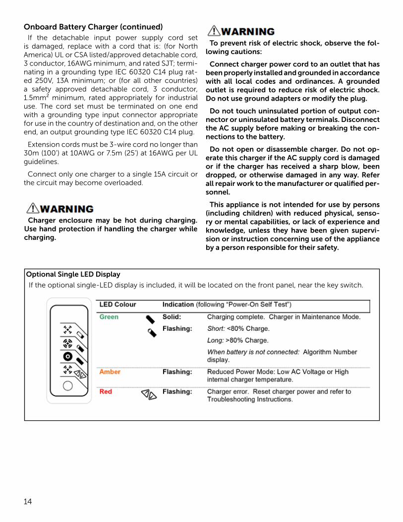
If the optional single-LED display is included, it will be located on the front panel, near the key switch.
Optional Single LED Display
15
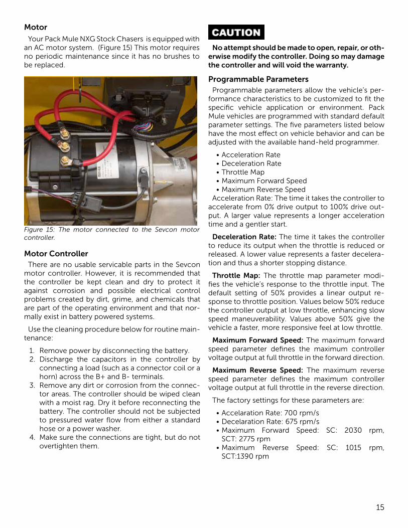
Motor
Your Pack Mule NXG Stock Chasers is equipped with an AC motor system. (Figure 15) This motor requires no periodic maintenance since it has no brushes to be replaced.
Figure 15: The motor connected to the Sevcon motor controller.
Motor ControllerThere are no usable servicable parts in the Sevcon
motor controller. However, it is recommended that the controller be kept clean and dry to protect it against corrosion and possible electrical control problems created by dirt, grime, and chemicals that are part of the operating environment and that nor-mally exist in battery powered systems.
Use the cleaning procedure below for routine main-tenance:
1. Remove power by disconnecting the battery.2. Discharge the capacitors in the controller by
connecting a load (such as a connector coil or a horn) across the B+ and B- terminals.
3. Remove any dirt or corrosion from the connec-tor areas. The controller should be wiped clean with a moist rag. Dry it before reconnecting the battery. The controller should not be subjected to pressured water flow from either a standard hose or a power washer.
4. Make sure the connections are tight, but do not overtighten them.
No attempt should be made to open, repair, or oth-erwise modify the controller. Doing so may damage the controller and will void the warranty.
Programmable ParametersProgrammable parameters allow the vehicle’s per-
formance characteristics to be customized to fit the specific vehicle application or environment. Pack Mule vehicles are programmed with standard default parameter settings. The five parameters listed below have the most effect on vehicle behavior and can be adjusted with the available hand-held programmer.
• Acceleration Rate• Deceleration Rate• Throttle Map• Maximum Forward Speed• Maximum Reverse Speed
Acceleration Rate: The time it takes the controller to accelerate from 0% drive output to 100% drive out-put. A larger value represents a longer acceleration time and a gentler start.
Deceleration Rate: The time it takes the controller to reduce its output when the throttle is reduced or released. A lower value represents a faster decelera-tion and thus a shorter stopping distance.
Throttle Map: The throttle map parameter modi-fies the vehicle’s response to the throttle input. The default setting of 50% provides a linear output re-sponse to throttle position. Values below 50% reduce the controller output at low throttle, enhancing slow speed maneuverability. Values above 50% give the vehicle a faster, more responsive feel at low throttle.
Maximum Forward Speed: The maximum forward speed parameter defines the maximum controller voltage output at full throttle in the forward direction.
Maximum Reverse Speed: The maximum reverse speed parameter defines the maximum controller voltage output at full throttle in the reverse direction.
The factory settings for these parameters are:
• Accelaration Rate: 700 rpm/s• Decelaration Rate: 675 rpm/s• Maximum Forward Speed: SC: 2030 rpm,
SCT: 2775 rpm• Maximum Reverse Speed: SC: 1015 rpm,
SCT:1390 rpm
16
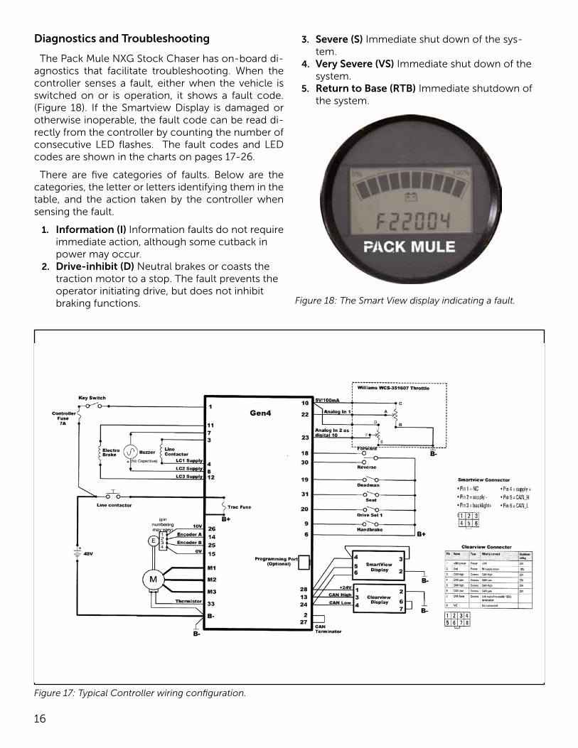
Figure 17: Typical Controller wiring configuration.
Diagnostics and Troubleshooting
The Pack Mule NXG Stock Chaser has on-board di-agnostics that facilitate troubleshooting. When the controller senses a fault, either when the vehicle is switched on or is operation, it shows a fault code. (Figure 18). If the Smartview Display is damaged or otherwise inoperable, the fault code can be read di-rectly from the controller by counting the number of consecutive LED flashes. The fault codes and LED codes are shown in the charts on pages 17-26.
There are five categories of faults. Below are the categories, the letter or letters identifying them in the table, and the action taken by the controller when sensing the fault.
1. Information (I) Information faults do not require immediate action, although some cutback in power may occur.
2. Drive-inhibit (D) Neutral brakes or coasts the traction motor to a stop. The fault prevents the operator initiating drive, but does not inhibit braking functions.
3. Severe (S) Immediate shut down of the sys-tem.
4. Very Severe (VS) Immediate shut down of the system.
5. Return to Base (RTB) Immediate shutdown of the system.
Figure 18: The Smart View display indicating a fault.
17
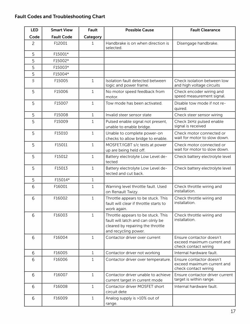
Fault Codes and Troubleshooting Chart
LED
Code
Smart View
Fault Code
Fault
Category
Possible Cause Fault Clearance
2 F12001 1 Handbrake is on when direction is selected.
Disengage handbrake.
5 F15001*
5 F15002*
5 F15003*
5 F15004*
5 F15005 1 Isolation fault detected between logic and power frame.
Check isolation between low and high voltage circuits
5 F15006 1 No motor speed feedback from motor.
Check encoder wiring and speed measurement signal.
5 F15007 1 Tow mode has been activated. Disable tow mode if not re-quired.
5 F15008 1 Invalid steer sensor state Check steer sensor wiring
5 F15009 1 Pulsed enable signal not present, unable to enable bridge.
Check 1kHz pulsed enable signal is received
5 F15010 1 Unable to complete power-on checks to allow bridge to enable.
Check motor connected or wait for motor to slow down.
5 F15011 1 MOSFET/IGBT s/c tests at power up are being held off.
Check motor connected or wait for motor to slow down.
5 F15012 1 Battery electrolyte Low Level de-tected
Check battery electrolyte level
5 F15013 1 Battery electrolyte Low Level de-tected and cut back.
Check battery electrolyte level
5 F15014* 1
6 F16001 1 Warning level throttle fault. Used on Renault Twizy.
Check throttle wiring and installation.
6 F16002 1 Throttle appears to be stuck. This fault will clear if throttle starts to work again.
Check throttle wiring and installation.
6 F16003 1 Throttle appears to be stuck. This fault will latch and can olnly be cleared by repairing the throttle and recycling power.
Check throttle wiring and installation.
6 F16004 1 Contactor driver over current Ensure contactor doesn’t exceed maximum current and check contact wiring
6 F16005 1 Contactor driver not working Internal hardware fault.
6 F16006 1 Contactor driver over temperature. Ensure contactor doesn’t exceed maximum current and check contact wiring
6 F16007 1 Contactor driver unable to achieve current target in current mode
Ensure contactor driver current target is within range.
6 F16008 1 Contactor driver MOSFET short circuit dete
Internal hardware fault.
6 F16009 1 Analog supply is >10% out of range.
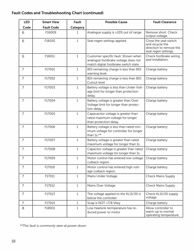
18
LED
Code
Smart View
Fault Code
Fault
Category
Possible Cause Fault Clearance
6 F16009 1 Analogue supply is >10% out of range. Remove short. Check output voltage.
6 F16010 1 Seat regen settings applied. Close the seat switch and recycle the direction to remove the seat regen settings.
6 F16011 1 Customer specific fault. Shown when analogue footbrake voltage does not match digital footbrake switch state.
Check footbrake wiring and installation.
7 F17001 1 BDI remaining charge is less than BDI warning level.
Charge battery
7 F17002 1 BDI remaining charge is less than BDI Cutout level
Charge battery
7 F17003 1 Battery voltage is less than Under Volt-age limit for longer than protection delay.
Charge battery
7 F17004 1 Battery voltage is greater than Over Voltage limit for longer than protec-tion delay.
Charge battery
7 F17005 1 Capacacitor voltage is greater than rated maximum voltage for longer than protection delay.
Charge battery
7 F17006 1 Battery voltage is less than rated min-imum voltage for controller for longer than 1s.**
Charge battery
7 F17007 1 Battery voltage is greater than rated maximum voltage for longer than 1s.
Charge battery
7 F17008 1 Capacitor voltage is greater than rated maximum voltage for longer than 1s.
Charge battery
7 F17009 1 Motor control has entered low voltage cutback region.
Charge battery
7 F17010 1 Motor control has entered high volt-age cutback region.
Charge battery
7 F17011 1 Mains Under Voltage Check Mains Supply
7 F17012 1 Mains Over Voltage Check Mains Supply
7 F17013 1 The voltage applied to the KL15/30 is below the controller
Check KL15/30 supply voltage
7 F17014 1 Vcap is NOT >7/8 Vkey Charge battery
8 F18001 1 Low heatsink termperature has re-duced power to motor
Allow controller to warm up to normal operating temperature.
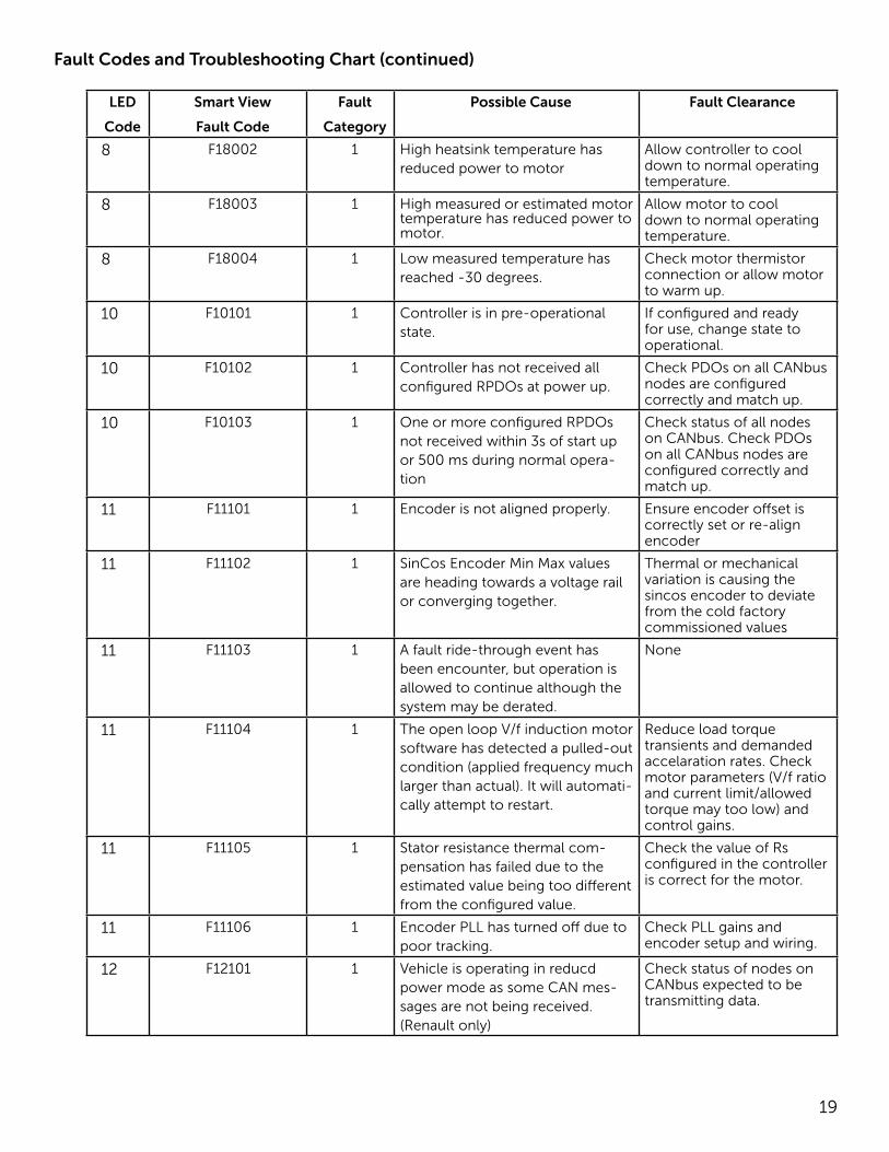
Fault Codes and Troubleshooting Chart (continued)
**This fault is commonly seen at power down.
19
LED
Code
Smart View
Fault Code
Fault
Category
Possible Cause Fault Clearance
8 F18002 1 High heatsink temperature has reduced power to motor
Allow controller to cool down to normal operating temperature.
8 F18003 1 High measured or estimated motor temperature has reduced power to motor.
Allow motor to cool down to normal operating temperature.
8 F18004 1 Low measured temperature has reached -30 degrees.
Check motor thermistor connection or allow motor to warm up.
10 F10101 1 Controller is in pre-operational state.
If configured and ready for use, change state to operational.
10 F10102 1 Controller has not received all configured RPDOs at power up.
Check PDOs on all CANbus nodes are configured correctly and match up.
10 F10103 1 One or more configured RPDOs not received within 3s of start up or 500 ms during normal opera-tion
Check status of all nodes on CANbus. Check PDOs on all CANbus nodes are configured correctly and match up.
11 F11101 1 Encoder is not aligned properly. Ensure encoder offset is correctly set or re-align encoder
11 F11102 1 SinCos Encoder Min Max values are heading towards a voltage rail or converging together.
Thermal or mechanical variation is causing the sincos encoder to deviate from the cold factory commissioned values
11 F11103 1 A fault ride-through event has been encounter, but operation is allowed to continue although the system may be derated.
None
11 F11104 1 The open loop V/f induction motor software has detected a pulled-out condition (applied frequency much larger than actual). It will automati-cally attempt to restart.
Reduce load torque transients and demanded accelaration rates. Check motor parameters (V/f ratio and current limit/allowed torque may too low) and control gains.
11 F11105 1 Stator resistance thermal com-pensation has failed due to the estimated value being too different from the configured value.
Check the value of Rs configured in the controller is correct for the motor.
11 F11106 1 Encoder PLL has turned off due to poor tracking.
Check PLL gains and encoder setup and wiring.
12 F12101 1 Vehicle is operating in reducd power mode as some CAN mes-sages are not being received. (Renault only)
Check status of nodes on CANbus expected to be transmitting data.
Fault Codes and Troubleshooting Chart (continued)
20
LED
Code
Smart View
Fault Code
Fault
Category
Possible Cause Fault Clearance
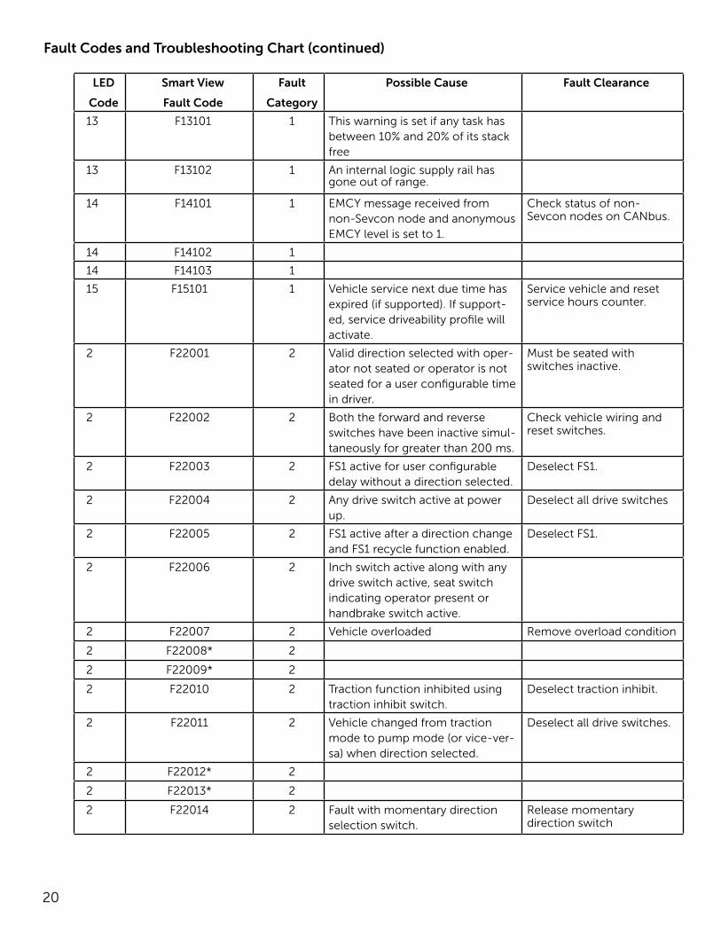
13 F13101 1 This warning is set if any task has between 10% and 20% of its stack free
13 F13102 1 An internal logic supply rail has gone out of range.
14 F14101 1 EMCY message received from non-Sevcon node and anonymous EMCY level is set to 1.
Check status of non-Sevcon nodes on CANbus.
14 F14102 1
14 F14103 1
15 F15101 1 Vehicle service next due time has expired (if supported). If support-ed, service driveability profile will activate.
Service vehicle and reset service hours counter.
2 F22001 2 Valid direction selected with oper-ator not seated or operator is not seated for a user configurable time in driver.
Must be seated with switches inactive.
2 F22002 2 Both the forward and reverse switches have been inactive simul-taneously for greater than 200 ms.
Check vehicle wiring and reset switches.
2 F22003 2 FS1 active for user configurable delay without a direction selected.
Deselect FS1.
2 F22004 2 Any drive switch active at power up.
Deselect all drive switches
2 F22005 2 FS1 active after a direction change and FS1 recycle function enabled.
Deselect FS1.
2 F22006 2 Inch switch active along with any drive switch active, seat switch indicating operator present or handbrake switch active.
2 F22007 2 Vehicle overloaded Remove overload condition
2 F22008* 2
2 F22009* 2
2 F22010 2 Traction function inhibited using traction inhibit switch.
Deselect traction inhibit.
2 F22011 2 Vehicle changed from traction mode to pump mode (or vice-ver-sa) when direction selected.
Deselect all drive switches.
2 F22012* 2
2 F22013* 2
2 F22014 2 Fault with momentary direction selection switch.
Release momentary direction switch
Fault Codes and Troubleshooting Chart (continued)
21
LED
Code
Smart View
Fault Code
Fault
Category
Possible Cause Fault Clearance
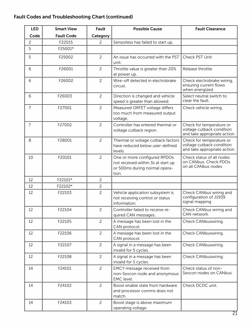
2 F22015 2 Sensorless has failed to start up.
5 F25001*
5 F25002 2 An issue has occurred with the PST unit.
Check PST Unit
6 F26001 2 Throttle value is greater than 20% at power up.
Release throttle
6 F26002 2 Wire-off detected in electrobrake circuit.
Check electrobrake wiring, ensuring current flows when energized.
6 F26003 2 Direction is changed and vehicle speed is greater than allowed.
Select neutral switch to clear the fault.
7 F27001 2 Measured ORFET voltage differs too much from measured output voltage.
Check vehicle wiring.
7 F27002 2 Controller has entered thermal or voltage cutback region.
Check for temperature or voltage cutback condition and take appropriate action.
8 F28001 2 Thermal or voltage cutback factors have reduced below user-defined levels.
Check for temperature or voltage cutback condition and take appropriate action.
10 F20101 2 One or more configured RPDOs not received within 3s at start up or 500ms during normal opera-tion.
Check status of all nodes on CANbus. Check PDOs on all CANbus nodes
12 F22101* 2
12 F22102* 2
12 F22103 2 Vehicle application subsystem is not receiving control or status information.
Check CANbus wiring and configuration of J1939 signal mapping.
12 F22104 2 Controller failed to receive re-quired CAN messages.
Check CANbus wiring and CAN network.
12 F22105 2 A message has been lost in the CAN protocol.
Check CANbuswiring.
12 F22106 2 A message has been lost in the CAN protocol.
Check CANbuswiring.
12 F22107 2 A signal in a message has been invalid for 5 cycles.
Check CANbuswiring.
12 F22108 2 A signal in a message has been invalid for 5 cycles.
Check CANbuswiring.
14 F24101 2 EMCY message received from non-Sevcon node and anonymous EMC level.
Check status of non-Sevcon nodes on CANbus.
14 F24102 2 Boost enable state from hardware and processor comms does not match.
Check DCDC unit.
14 F24103 2 Boost stage is above maximum operating voltage.
Fault Codes and Troubleshooting Chart (continued)
22
LED
Code
Smart View
Fault Code
Fault
Category
Possible Cause Fault Clearance
14 F24104 2 DC input voltage is under the specified minimum.
Check battery.
14 F24105 2 DC input voltage is over the speci-fied maximum.
Check battery
14 F24106 2 Output voltage is over the speci-fied maximum.
Check vehicle wiring.
1 F31001* 3
2 F32001* 3
4 F34001* 3
4 F34002* 3
4 F34003* 3
4 F34004 3 Time to close breaker on GpAC has expired.
Cycle power and restart breaker close sen
5 F35001 3 Motor isolation contactor is open circuit.
Check isolator contactor and wiring
5 F35002 3 Motor terminal is open circuit or disconnected from controller
Check motor wiring. Check controller condition.
5 F35003 3 No speed feedback from motor. Check encoder wiring and speed measurement signal.
7 F37003 3 Battery voltage has dropped below critical level.
Check controller voltage supply.
10 F30101 3 One or more configured RPDOs not received within 3s at start up or 500ms during normal opera-tion.
Check status of all nodes on CANbus
11 F31101 3 Controller is unable to control a current in the field winding.
Check field is wired to correct terminals.
11 F31102 3 The motor control protection subsystem unexpectedly disabled the PWM.
Check for the presence of other faults that may indicate root cause of the problem.
12 F32101* 3
12 F32102 3 Unable to transmit EMCY message. Internal software fault.
13 F33101 3 Internal software fault. Internal software fault.
13 F33102 3 Out of memory. Internal software fault.
13 F33103 3 Unknown error raised by motor model code.
Internal software fault.
13 F33104 3 Unable to allocate timer. Internal software fault.
13 F33105 3 Unable to post message to queue Internal software fault.
13 F33106 3 Unable to create task in scheduler Internal software fault.
13 F33107* 3
13 F33108 3 Internal software fault. Internal software fault.
13 F33109 3 Internal software fault. Internal software fault.
13 F33110 3 Internal software fault. Internal software fault.
Fault Codes and Troubleshooting Chart (continued)
23
LED
Code
Smart View
Fault Code
Fault
Category
Possible Cause Fault Clearance
13 F33111 3 Internal software fault. Internal software fault.
13 F33112 3 Internal software fault. Internal software fault.
13 F33113 3 Internal software fault. Internal software fault.
13 F33114 3 Internal software fault. Internal software fault.
13 F33115 3 Internal software fault. Internal software fault.
13 F33116 3 Internal software fault. Internal software fault.
13 F33117* 3
13 F33118* 3
13 F33119 3 Internal software fault. Internal software fault.
13 F33120 3 Current sensor auto-zero current out of range.
Internal software fault.
13 F33121 3 Communication error between host and DSP processors
Internal software fault
13 F33122 3 Motor rotation detected as wrong direction.
Check motor wiring
13 F33123 3 Motor rotation stalled. Check motor wiring
13 F33124 3 Internal software fault. Internal software fault.
14 F34101 3 EMCY message received from non-Sevcon node and anonymous EMCY level is set to 3.
Check status of non-Sevcon nodes on CANbus.
1 F41001 4 EEPROM or flash configuration data corrumpted and data cannot be recovered.
1 F41002 4 VPDO mapped to non-existant or invalid object.
Check all VPDO mappings.
1 F41003 4 At least one configuration object is out of range.
Set configuration object to valid value. Out of range object can be identified using 0x6621 or Engineering DVT CLI window.
1 F41004 4 At least one configuration object is out of range where one object’s range depends on another.
Check all dynamic range objects. Engineering DEV CLI window indicates the object out of range.
1 F41005 4 Unable to automatically configure I/O and vehicle setup.
Check autoconfiguration objects.
1 F41006 4 Unable to set battery voltage. Check auxillary drives support low voltage configuration.
2 F42001* 4
4 F44001 4 Line contactor did not close when coil is energized.
Check line contactor and wiring.
4 F44002 4 Line contactor closed when coil is deenergized.
Check line contactor and wiring.
Fault Codes and Troubleshooting Chart (continued)
24
LED
Code
Smart View
Fault Code
Fault
Category
Possible Cause Fault Clearance
5 F45001* 4
5 F45002* 4
5 F45003 4 VERLOG signal failure. Check peripheral devices.
6 F46001 4 Digital input wire-off. Check wiring.
6 F46002 4 Analogue input outside of allowed range.
Check wiring
6 F46003 4 Contactor driver over current. Ensure contactor doesn’t exceed maximum current and check contactor wiring.
6 F46004 4 Contactor driver unable to achieve current target in current mode.
Ensure contactor driver current target is within range.
6 F46005 4 Contactor driver not working. Internal hardware fault.
6 F46006 4 Contactor driver over temperature. Ensure contactor driver doesn’t exceed maximum current and check contac-tor wiring.
6 F46007 4 Contactor driver unable to achieve current target in current mode.
Ensure contactor driver current target is within range.
6 F46008 4 Contactor driver MOSFET short circuit detected.
Internal hardware fault.
7 F47002 4 Capacitor voltage did not rise above 5V at power up.
Check power wiring.
7 F47003 4 The voltage applied to the KL 15/30 is above the controller rated maximum.
Check KL 15/30 voltage.
8 F48001 4 Controller heat sink has reached citical high temperature and has shut down.
Allow controller to cool down to normal operating temperatures.
11 F41101 4 Encoder wire-off is detected. Check encoder wiring.
11 F41102 4 Motor current exceeded control-ler-rated maximum.
Check motor configuration. and wiring.
11 F41103 4 Motor controller unableto main-tain control of motor currents.
Check motor configuration. ensure motor speed is not too high.
11 F41104 4 Motor control tripped due to mot-er overspeed.
Check motor configuration. ensure motor speed is not too high.
11 F41105 4 Encoder is not aligned properly. Ensure encoder offset is correctgly set or realign encoder.
11 F41106 4 Large rate of change of current detected multiple times. Suspect-ed MOSFET, motor or wiring short circuit.
Check motor wiring, especially for motor terminals shorted to B-. Check controller condition.
11 F41107 4 Measured capacitor voltage has exceeded controller maximum.
Check motor configuration and wiring.
Fault Codes and Troubleshooting Chart (continued)
25
LED
Code
Smart View
Fault Code
Fault
Category
Possible Cause Fault Clearance
11 F41108 4 Unable to control output current. Check wiring.
12 F42101 4 CANbus fault condition detected on multinode system.
Check CANbus wiring.
12 F42102 4 CANopen slave has not transmit-ted boot-up message at power up.
Check status of all nodes on CANbus.
12 F42103 4 CANbus fault condition detected on multinode system.
Check CANbus wiring.
12 F42104 4 CANbus fault condition detected on multinode system.
Check CANbus wiring.
12 F42105 4 CANbus fault condition detected on multinode system.
Check CANbus wiring.
12 F42106 4 CANbus fault condition detected on multinode system.
Check CANbus wiring.
12 F42107 4 CANbus fault condition detected on multinode system.
Check CANbus wiring.
12 F42108 4 CANbus fault condition detected on multinode system.
Check CANbus wiring.
12 F42110 4 Received RPDO doesn’t contain enough bytes.
Check PDLOs on all CANbus nodes are configured correctly and match up.
12 F42111 4 Heartbeat not received within con-figured time out.
Check status of all nodes on CANbus.
12 F42112* 4 Internal CANbus fault. Internal software fault.
12 F42113 4 Internal CANbus fault. Internal software fault.
12 F42114 4 Internal CANbus fault. Internal software fault.
12 F42115 4 Internal CANbus fault. Internal software fault.
12 F42116 4 Internal CANbus fault. Internal software fault.
12 F42117 4 Internal CANbus fault. Internal software fault.
12 F42118 4 Internal CANbus fault. Internal software fault.
12 F42119 4 Internal CANbus fault. Internal software fault.
12 F42120 4 Internal CANbus fault. Internal software fault.
12 F42121 4 Internal CANbus fault. Internal software fault.
12 F42122 4 Internal CANbus fault. Internal software fault.
12 F42123 4 Internal CANbus fault. Internal software fault.
12 F42124 4 Internal CANbus fault. Internal software fault.
12 F42125* 4
12 F42126* 4
13 F43101 4 DSP reports invalid protocol ver-sion on dual processor platform.
Internal software fault.
13 F43102 4 Internal hardware fault. Internal hardware fault.
13 F43103 4 Attempting to set too man faults. Internal software fault.
13 F43104 4 Communication error between host and DSP processors.
Internal hardware fault.
Fault Codes and Troubleshooting Chart (continued)
26
LED
Code
Smart View
Fault Code
Fault
Category
Possible Cause Fault Clearance
13 F43105 4 Less than 10% of the stack is free on one of the RTOS tasks.
Internal hardware fault.
13 F43106 4 An internal logic supply rail has gone out of range.
14 F44101 4 EMCY message received from non-Sevcon node and anonymous EMCY level was set to 4.
CVheck status of non-Sevcon nodes on CANbus.
1 F51001 5 Detected controller hardware ver-sion incompatible with software.
Check correct software is programmed into control-ler. Reprogram if necessary.
1 F51002 5 Calibration settings in controller are out of range.
Controller requires recali-bration in production.
3 F53001 5 Voltage on B+ terminal exceeds rated maximum for controller.
Check battery condition and wiring.
3 F53002 5 Motor current exceeded control-ler-rated maximum.
Check motor configuration and wiring.
3 F53003 5 MOSFET/IGBT s/c detection on M1 top devices.
Check motor wiring. Check controller condition.
3 F53004 5 MOSFET/IGBT s/c detection on M1 bottom devices.
Check motor wiring. Check controller condition.
3 F53005 5 MOSFET/IGBT s/c detection on M2 top devices.
Check motor wiring. Check controller condition.
3 F53006 5 MOSFET/IGBT s/c detection on M2 bottom devices.
Check motor wiring. Check controller condition.
3 F53007 5 MOSFET/IGBT s/c detection on M3 top devices.
Check motor wiring. Check controller condition.
3 F53008 5 MOSFET/IGBT s/c detection on M3 bottom devices..
Check motor wiring. Check controller condition.
3 F53009 5 Unable to complete MOSFET/IGBT tests at power up.
Internal software fault.
3 F53010 5 IGBT driver failure Check status of IGBT
3 F53011 5 IGBT driver failure Check status of IGBT
3 F53012 5 IGBT driver failure Check status of IGBT
3 F53013 5 IGBT driver failure Check status of IGBT
3 F53014 5 IGBT driver failure Check status of IGBT
3 F53015 5 IGBT driver failure Check status of IGBT
13 F53101 5 Unable to identify hardware Internal hardware fault
14 F54101 5 EMCY message received from non-Sevcon node and anonymous EMCY level is set to 5.
Check status of non-Sevcon nodes on CANbus.
Fault Codes and Troubleshooting Chart (continued)

27
Appendix A: Industry Standards
The following text is provided as recommended by Part II, “For the User”, of ANSI/ITSDF B56.8-2011, Safety Standard for Personnel and Burden Carriers. The manufacturer strongly endorses the contents of this specification.
6 GENERAL SAFETY PRACTICES
6.1 Introduction
6.1.1 Like other machines, carriers can cause inju-ry if improperly used or maintained. Part II contains broad safety practices applicable to carrier operation. Before operation, the user shall establish such addi-tional specific safety practices as may reasonably be required for safe operation.
6.1.2 Premise review — The user shall periodical-ly review their premises, and as conditions warrant, identify areas where carriers should not be operated and to identify possible hazards such as the following examples:
(a) Steep Grade — In areas where steep grades exist, carrier operation should be restricted to the desig-nated vehicle’s pathways where possible, and shall be identified with a suitable warning giving the following information: “Warning, steep grade.”
(b) Wet Areas — Wet areas could cause a carrier to lose traction and could affect steering, stability and braking.
(c) Sharp Turns, Blind Spots, Bridge Approaches —Sharp turns, blind spots, bridge approaches, and oth-er potentially hazardous areas shall be identified with a suitable warning to the operator of the nature of the hazard and stating the proper precautions to be taken to avoid the hazard.
(d) Loose Terrain — Loose terrain could cause a carrier to lose traction and could affect steering, sta-bility, and braking.
6.2 Operation
Experience has shown that carriers, which comply with the provisions, stated in paragraphs 9.4, 9.5, and 9.6 are stable when properly operated and when op-erated in accordance with specific safety rules and practices established to meet actual operating terrain and conditions. However, improper operation, faulty maintenance, or poor housekeeping may contribute to a condition of instability and defeat the purpose of the standard. Some of the conditions which may affect stability are failure of the user to follow safety practices; also, ground and floor conditions, grade,
speed, loading, the operation of the carrier with im-proper loads, battery weight, dynamic and static forces, and the judgment exercised by the carrier op-erator.
(a) The user shall train carrier operators to adhere strictly to the operating instructions stated in this Standard.
(b) The user shall survey specific operating condi-tions and environment, and establish and train carrier operators to comply with additional, specific safety practices.
6.3 Nameplates, Markings, Capacity, and Modifications
6.3.1 The user shall maintain in a legible condition all nameplates, warnings, and instructions, which are supplied by the manufacturer.
6.3.2 Except as provided in 6.3.4, no modifications or alterations to a carrier, which may affect the ca-pacity, stability, or safe operation of the carrier, shall be made without the prior written approval of the original carrier manufacturer or a successor there-of. When the carrier manufacturer or its successor approves a modification or alteration, appropriate changes shall be made to capacity plates, decals, tags, and operation and maintenance manuals.
6.3.3 As required under paragraphs 6.3.1 or 6.3.2, the manufacturer shall be contacted to secure new nameplates, warnings, or instructions, which shall then be affixed in their proper place on the carrier.
6.3.4 In the event that the carrier manufacturer is no longer in business and there is no successor in interest to the business, the user may arrange for a modification or alteration to a carrier, provided how-ever, the controlling party shall:
(1) Arrange for the modification or alteration to be designed, tested, and implemented by an engineer(s) expert in carrier(s) and their safety;
(2) Maintain a permanent record of the design, test(s), and implementation of the modification or al-teration;
(3) Make appropriate changes to the capacity plate(s), decals, tags, and operation and maintenance manuals;
(4) Affix a permanent and readily visible label on the carrier stating the manner in which the carrier has been modified or altered together with the date of the modification or alteration, and the name of the organization that accomplished the tasks.
28
6.4 Changing and Charging Storage Batteries for Electric Personnel and Burden Carriers
6.4.1 The user shall require battery changing and charging facilities and procedures to be in accor-dance with ANSI/NFPA 505 or as required by local ordinance.
6.4.2 The user shall periodically inspect facilities and review procedures to be certain that ANSI/NFPA 505 or as required by local ordinance, are strictly complied with, and shall familiarize carrier operators with it.
6.4.3 Maintenance and storage areas for carriers shall be properly ventilated to avoid fire hazards in accordance with applicable fire codes and ordinanc-es.
Ventilation for internal combustion engine powered carriers shall be provided to remove flammable va-pors (gases), fumes and other flammable materials. Consult applicable fire codes for specific levels of ventilation.
Ventilation for electric powered carriers shall be provided to remove the accumulation of flammable hydrogen gas emitted during the battery charging process.
The amount of hydrogen gas emitted depends upon a number of factors such as the condition of the batteries, the output rate of the battery charger and the amount of time the batteries are on charge. Because of the highly volatile nature of hydrogen gas and its propensity to accumulate in pockets, a min-imum number of air changes per hour is required during charging.
Consult applicable fire and safety codes for the spe-cific ventilation levels required as well as the use of explosion proof electrical apparatus. SAE J1718 can be followed to check for hydrogen gas levels.
6.5 Hazardous Locations
6.5.1 The user shall determine the hazard classi-fication of the particular atmosphere or location in which the carrier is to be used in the accordance with ANSI/NFPA 505.
6.5.2 The user shall permit in hazardous areas only those carriers approved and of the type required by ANSI/NFPA 505.
6.6 Lighting for Operating Area
The user, in accordance with his responsibility to survey the environment and operating conditions, shall determine if the carrier requires lights and, if so, shall equip the carrier with appropriate lights.
6.7 Control of Noxious Gases and Fumes
When equipment powered by internal combus-tion engines is used in enclosed areas, the atmo-sphere shall be maintained within limits specified in the American Conference of Governmental Indus-trial Hygienists publication, “Threshold Limit Values for Chemical Substances and Physical Agents in the Workroom Environment.” This may be accomplished by ventilation provided by the user, or the installation, use, and proper maintenance of emission control equipment recommended or provided by the man-ufacturer of the equipment.
6.8 Warning Device(s)
6.8.1 The user shall make periodic inspections of the carrier to be certain that the sound-producing and/or visual device(s) if so equipped are maintained in good operating condition.
6.8.2 The user shall determine if operating con-ditions require the carrier to be equipped with addi-tional sound producing or visual devices or both and be responsible for providing and maintaining such devices, in accordance with the manufacturer’s rec-ommendations.
6.9 Safety Interlocks
The user shall make periodic inspections of the car-rier to be certain that the safety interlock system, if so equipped, is operating properly.
7 OPERATING SAFETY RULES AND PRACTICES
7.1 Personnel and Burden Carrier Operator Qualifications
Only persons who are trained in the proper opera-tion of the carrier shall be authorized to operate the carrier. Operators shall be qualified as to visual, au-ditory, physical, and mental ability to safely operate the equipment according to Section 7, and all other applicable parts of this Standard and the operators’ manual.
7.2 Personnel and Burden Carrier Operators’ Training
7.2.1 The user shall conduct an operators’ training program.
7.2.2 Successful completion of the operators’ train-ing program by the operator shall be required be-fore operation of the carrier. The program shall be presented in its entirely to all new operators and not condensed for those claiming previous experience.
7.2.3 The user shall include as a minimum in the operators’ training program the following:
29
(a) Instructional material provided by the manu-facturer including the operators’ manual;
(b) Emphasis on safety of passengers, material loads, carrier operator, and other person(s);
(c) General safety rules contained within this Stan-dard and the additional specific rules determined by the user in accordance with this Standard, and why they were formulated;
(d) Introduction of equipment, control locations and functions, and explanation of how they work when used properly and when used improperly; and surface conditions, grade, and other conditions of the environment which could affect carrier operation;
(e) Operator competency evaluations.
7.3 Personnel and Burden Carrier Operator Responsibility
7.3.1 General Operator Responsibility
7.3.1.1 Read and follow operators’ manual.
7.3.1.2 Do not operate carrier under the influence of drugs and alcohol.
7.3.1.3 Safeguard the pedestrians at all times. Do not drive carrier in a manner that would endanger other persons.
7.3.1.4 Riding on the carrier by persons other than the operator is authorized only on personnel seat(s) provided by the manufacturer. All parts of each per-son’s body shall remain within the plan view outline of the carrier.
7.3.1.5 When a carrier is to be left unattended, stop the carrier, apply the parking brake, stop the engine or turn off power, turn off the control or ignition cir-cuit, and remove the key if provided. Additionally, for electric carriers, the forward and reverse directional controls should be neutralized if a means is provided. Block the wheels if the carrier is on an incline.
7.3.1.6 A carrier is considered unattended when the operator is 7.6m (25 ft) or more from the carrier which remains in his view, or whenever the operator leaves the carrier and it is not within his view. When the operator is dismounted and within 7.6m (25 ft) of the carrier still in his view, he still must have controls neutralized, and the parking brake(s) set to prevent movement.
7.3.1.7 Maintain a safe distance from potential hazards, such as edges of ramps and platforms.
7.3.1.8 Use only approved carriers in hazardous locations, as defined in the appropriate safety stan-dards.
7.3.1.9 Report all accidents to the user.
7.3.1.10 Do not add to, or modify, the carrier.
7.3.1.11 Carriers shall not be parked or left unat-tended such that they block or obstruct fire aisles, access to stairways, or fire equipment.
7.3.1.12 Only operate carrier while within opera-tor’s station.
7.3.2 Traveling
7.3.2.1 Observe all traffic regulations, including au-thorized speed limits. Under normal traffic conditions keep to the right. Maintain a safe distance, based on speed of travel, from a carrier or vehicle ahead; and keep the carrier under control at all times.
7.3.2.2 Yield the right of way to pedestrians, am-bulances, fire trucks, or other carriers/vehicles in emergency situations.
7.3.2.3 Do not pass another carrier or vehicle trav-eling in the same direction at intersections, blind spots, or at other dangerous locations.
7.3.2.4 Keep a clear view of the path of travel, ob-serve other traffic and personnel, and maintain a safe clearance.
7.3.2.5 Slow down or stop, as conditions dictate, and activate the sound-producing warning device at cross aisles and when visibility is obstructed at other locations.
7.3.2.6 Ascend or descend grades slowly.
7.3.2.7 Avoid turning, if possible, and use extreme caution on grades, ramps, or inclines; normally travel straight up and down.
7.3.2.8 Under all travel conditions the carrier shall be operated at a speed that will permit it to be brought to a stop in a safe manner.
7.3.2.9 Make starts, stops, turns, or direction rever-sals in a smooth manner so as not to shift the load, endanger passengers, or lose control of the carrier.
7.3.2.10 Do not operate carrier in a dangerous manner.
7.3.2.11 Slow down when approaching, or on, wet or slippery surfaces.
7.3.2.12 Do not drive carrier onto any elevator unless specifically authorized to do so. Approach elevators slowly, and then enter squarely after the elevator car is properly leveled. Once on the elevator, neutralize the controls, shut off power, and set parking brakes. It is advisable that all other personnel leave the elevator before a carrier is allowed to enter or exit.
30
7.3.2.13 Avoid running over loose objects, potholes, and bumps.
7.3.2.14 Reduce carrier speed to negotiate turns.
7.3.2.15 Avoid any action verbal or physical by an operator or passenger, which could cause the oper-ator to be distracted.
7.3.3 Loading
7.3.3.1 Refer to operators’ manual for loading in-struction.
7.3.3.2 Handle only stable and safely arranged loads. When handling off-center loads, which cannot be centered, operate with extra caution.
7.3.3.3 Handle only loads within the capacity of each cargo area of the carrier as specified by the manu-facturer.
7.3.3.4 Avoid material loads exceeding the physical dimensions of the carrier or as specified by the carrier manufacturer.
7.3.4 Operator Care of Personnel and Burden Carriers
7.3.4.1 Read and follow operators’ manual.
7.3.4.2 At the beginning of each shift during which the carrier will be used, the operator shall check the carrier condition and inspect the tires, warning de-vices, lights, battery(s), speed and directional con-trollers, brakes, safety interlocks, and steering mech-anism. If the carrier is found to be in need of repair or is in any way unsafe, the matter shall be reported immediately to the user and the carrier shall not be operated until restored to safe operating condition.
7.3.4.3 If during operation the carrier becomes un-safe in any way, the matter shall be reported immedi-ately to the user, and the carrier shall not be operated until it has been restored to safe operating condition.
7.3.4.4 Do not make repairs or adjustments unless specifically trained and authorized to do so.
7.3.4.5 Before refueling, the engine shall be stopped and allowed to cool. The operator and passengers shall leave the carrier before refueling.
7.3.4.6 Spillage of hazardous materials shall be con-tained immediately and addressed via appropriate hazardous materials regulations.
7.3.4.7 Do not operate a carrier with a leak in the fuel system or battery(s). Battery(s) shall be charged and serviced per manufacturer’s instructions.
7.3.4.8 Do not use open flames for checking elec-trolyte level in storage battery(s) or liquid level in fuel
tanks.
8 MAINTENANCE PRACTICES
8.1 Introduction
Carriers may become hazardous if maintenance is neglected. Maintenance facilities, trained personnel, and procedures shall be provided. Such facilities may be on or off the premises.
8.2 Maintenance Procedures
Maintenance and inspection of all carriers shall be performed in conformance with the following prac-tices and should follow the manufacturer’s recom-mendations.
(a) A scheduled preventive maintenance, lubrica-tion, and inspection system shall be followed.
(b) Only trained and authorized personnel shall be permitted to maintain, repair, adjust, and inspect car-riers.
(c) Before undertaking maintenance or repair, fol-low the manufacturer’s recommendations for immo-bilizing the carrier.
(d) Chock wheels and support carrier before work-ing underneath it.
(e) Before disconnecting any part of the engine fuel system, be sure the shutoff valve, if so equipped, is closed and follow carrier manufacturer’s recom-mended practice.
(f) Operation to check performance of the carrier shall be conducted in an authorized area where suit-able conditions exist, free of vehicular and pedestrian traffic.
(g) Before returning carrier to service, follow the manufacturer’s instructions and recommended pro-cedures.
(h) Avoid fire hazards and have fire protection equipment present in the work area. Do not use an open flame to check level or leakage of fuel, battery electrolyte, or coolant.
(i) Properly ventilate the work area in accordance with applicable regulations or local ordinance.
(j) Handle fuel cylinders with care. Physical damage, such as dents, scrapes, or gouges, may dangerously weaken the tank and make it unsafe for use.
(k) Brakes, steering mechanisms, speed and direc-tional control mechanisms, warning devices, lights, governors, guards, and safety devices shall be in-spected regularly and maintained in accordance with manufacturer’s recommendations.
31
(l) Carriers or devices designed and approved for hazardous area operation shall be inspected to en-sure that maintenance preserves the original ap-proved safe operating features.
(m) Fuel systems shall be checked for leaks and condition of parts. If a leak is found, action shall be taken to prevent the use of the carrier until the cause of the leak has been repaired.
(n) The carrier manufacturer’s capacity, operation, and maintenance instruction plated, tags, or decals shall be maintained in legible condition.
(o) Batteries, motors, speed and directional con-trollers, limit-switches, protective-devices, electrical conductors/insulators, and connections shall be in-spected and maintained per carrier manufacturer’s recommendation.
(p) Carriers shall be kept clean to minimize hazards and facilitate detection of components needing ser-vice.
(q) Modifications and additions which affect capac-ity and safe carrier operation shall not be performed without manufacturer’s prior written authorization; where authorized modifications have been made, the user shall ensure that capacity, operation, warning, and maintenance instruction plates, tags, or safety labels are changed accordingly.
(r) Care shall be taken to ensure that all replacement parts are interchangeable with the original parts and of a quality at least equal to that provided in the orig-inal equipment.
(s) Disconnect batteries, negative connection(s) first. When reconnecting, connect positive connec-tion first.
(t) Hydraulic systems, if so equipped, shall be checked for leaks, for condition of parts. Keep body and hands away from pin-holes or nozzles that eject fluids under high pressure. Use paper or cardboard, not hands, to check for leaks.
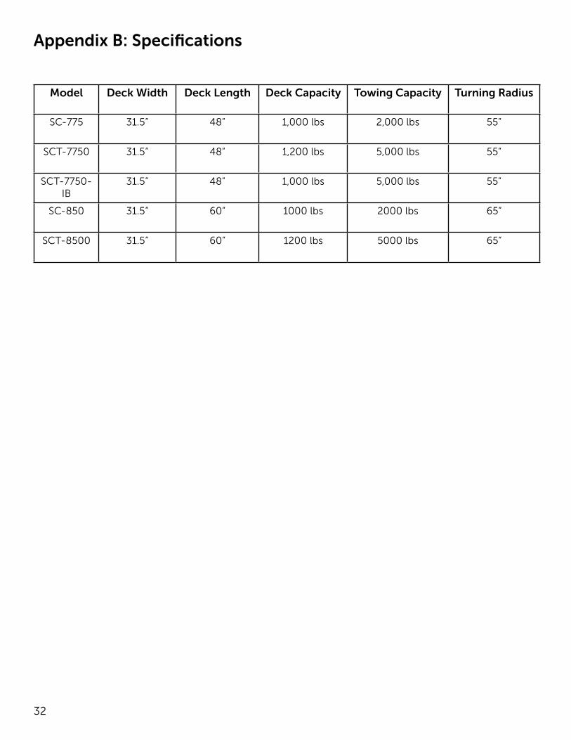
32
Model Deck Width Deck Length Deck Capacity Towing Capacity Turning Radius
SC-775 31.5” 48” 1,000 lbs 2,000 lbs 55”
SCT-7750 31.5” 48” 1,200 lbs 5,000 lbs 55”
SCT-7750-IB
31.5” 48” 1,000 lbs 5,000 lbs 55”
SC-850 31.5” 60” 1000 lbs 2000 lbs 65”
SCT-8500 31.5” 60” 1200 lbs 5000 lbs 65”
Appendix B: Specifications

33
This page intentionally left blank.
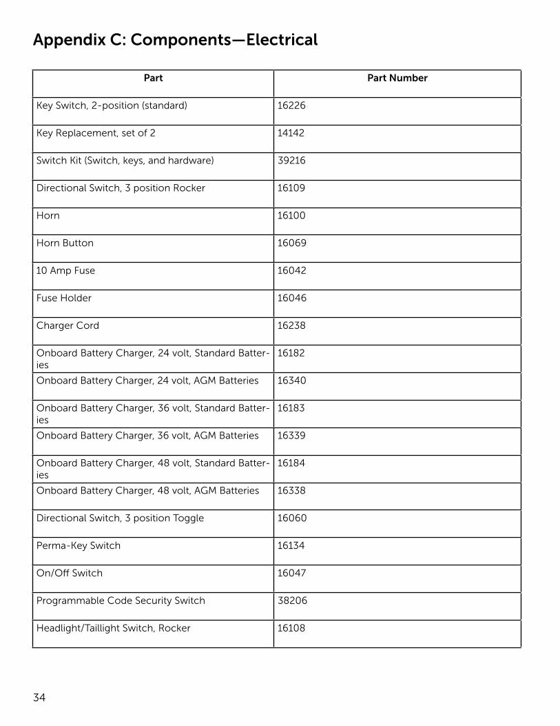
34
Appendix C: Components—Electrical
Part Part Number
Key Switch, 2-position (standard) 16226
Key Replacement, set of 2 14142
Switch Kit (Switch, keys, and hardware) 39216
Directional Switch, 3 position Rocker 16109
Horn 16100
Horn Button 16069
10 Amp Fuse 16042
Fuse Holder 16046
Charger Cord 16238
Onboard Battery Charger, 24 volt, Standard Batter-ies
16182
Onboard Battery Charger, 24 volt, AGM Batteries 16340
Onboard Battery Charger, 36 volt, Standard Batter-ies
16183
Onboard Battery Charger, 36 volt, AGM Batteries 16339
Onboard Battery Charger, 48 volt, Standard Batter-ies
16184
Onboard Battery Charger, 48 volt, AGM Batteries 16338
Directional Switch, 3 position Toggle 16060
Perma-Key Switch 16134
On/Off Switch 16047
Programmable Code Security Switch 38206
Headlight/Taillight Switch, Rocker 16108
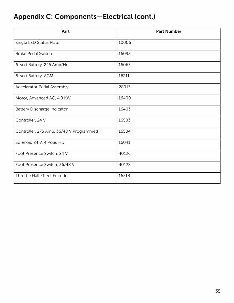
35
Appendix C: Components—Electrical (cont.)
Part Part Number
Single LED Status Plate 10006
Brake Pedal Switch 16093
6-volt Battery, 245 Amp/Hr 16063
6-volt Battery, AGM 16211
Accelarator Pedal Assembly 28013
Motor, Advanced AC, 4.0 KW 16400
Battery Discharge Indicator 16403
Controller, 24 V 16503
Controller, 275 Amp, 36/48 V Programmed 16504
Solenoid 24 V, 4 Pole, HD 16041
Foot Presence Switch, 24 V 40126
Foot Presence Switch, 36/48 V 40128
Throttle Hall Effect Encoder 16318
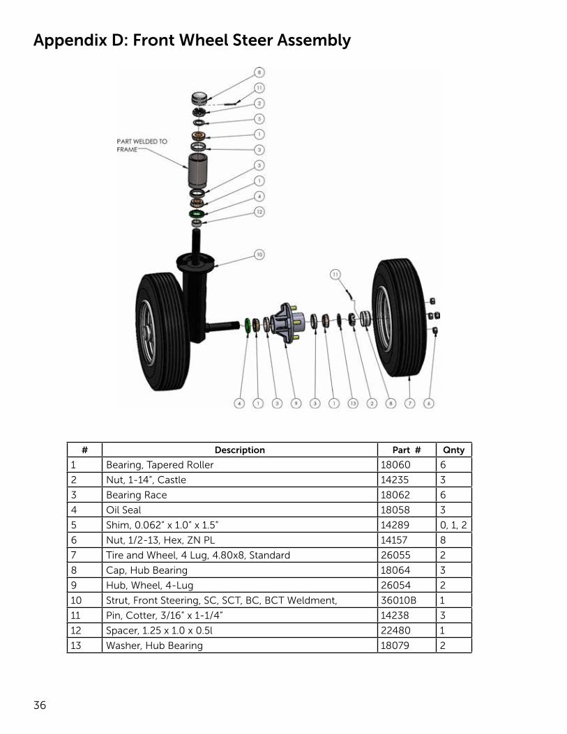
36
Appendix D: Front Wheel Steer Assembly
# Description Part # Qnty
1 Bearing, Tapered Roller 18060 6
2 Nut, 1-14”, Castle 14235 3
3 Bearing Race 18062 6
4 Oil Seal 18058 3
5 Shim, 0.062” x 1.0” x 1.5” 14289 0, 1, 2
6 Nut, 1/2-13, Hex, ZN PL 14157 8
7 Tire and Wheel, 4 Lug, 4.80x8, Standard 26055 2
8 Cap, Hub Bearing 18064 3
9 Hub, Wheel, 4-Lug 26054 2
10 Strut, Front Steering, SC, SCT, BC, BCT Weldment, 36010B 1
11 Pin, Cotter, 3/16” x 1-1/4” 14238 3
12 Spacer, 1.25 x 1.0 x 0.5l 22480 1
13 Washer, Hub Bearing 18079 2
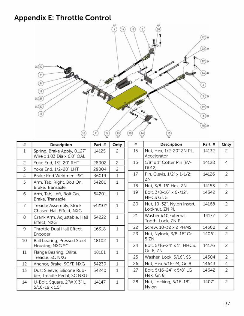
37
Appendix E: Throttle Control
# Description Part # Qnty
1 Spring, Brake Apply, 0.127” Wire x 1.03 Dia x 6.0” OAL
14125 2
2 Yoke End, 1/2-20” RHT 28002 2
3 Yoke End, 1/2-20” LHT 28004 2
4 Brake Rod Weldment-SC 36019 1
5 Arm, Tab, Right, Bolt On, Brake, Transaxle,
54200 1
6 Arm, Tab, Left, Bolt On, Brake, Transaxle,
54201 1
7 Treadle Assembly, Stock Chaser, Hall Effect, NXG
54210Y 1
8 Crank Arm, Adjustable, Hall Effect, NXG
54222 1
9 Throttle Dual Hall Effect, Encoder
16318 1
10 Ball bearing, Pressed Steel Housing, NXG SC
18102 1
11 Flange Bearing, Oilite, Treadle, SC NXG
18101 1
12 Anchor, Brake, SC/T, NXG 54230 1
13 Dust Sleeve; Silicone Rub-ber, Treadle Pedal, SC NXG
54240 1
14 U-Bolt, Square, 2”W X 3” L, 5/16-18 x 1.5”
14147 1
# Description Part # Qnty
15 Nut, Hex, 1/2-20” ZN PL, Accelerator
14132 2
16 1/8” x 1” Cotter Pin (EV-D012)
14128 4
17 Pin, Clevis, 1/2” x 1-1/2: ZN
14126 2
18 Nut, 3/8-16” Hex, ZN 14153 2
19 Bolt, 3/8-16” x 6-/12”, HHCS Gr. 5
14342 2
20 Nut, 10-32”, Nylon Insert, Locknut, ZN PL
14168 2
21 Washer,#10,External Tooth, Lock, ZN PL
14177 2
22 Screw, 10-32 x 2 PHMS 14360 2
23 Nut, Nylock, 3/8-16” Gr. 5 ZN
14061 2
24 Bolt, 5/16-24” x 1”, HHCS, Gr. 8, ZN
14176 2
25 Washer, Lock, 5/16”, SS 14304 2
26 Nut, Hex 5/16-24, Gr. 8 14643 4
27 Bolt, 5/16-24” x 5/8” LG Hex, Gr. 8
14642 2
28 Nut, Locking, 5/16-18”, Nylon
14071 2
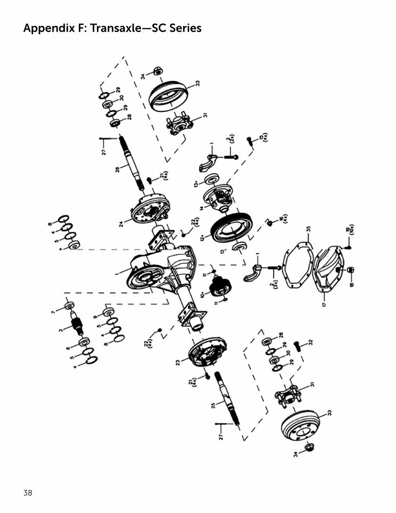
38
Appendix F: Transaxle—SC Series
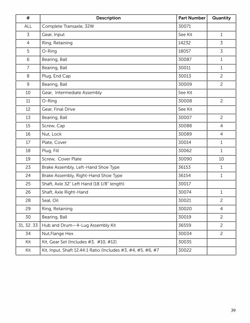
39
# Description Part Number Quantity
ALL Complete Transaxle, 32W 30071
3 Gear, Input See Kit 1
4 Ring, Retaining 14232 3
5 O-Ring 18057 3
6 Bearing, Ball 30087 1
7 Bearing, Ball 30011 1
8 Plug, End Cap 30013 2
9 Bearing, Ball 30009 2
10 Gear, Intermediate Assembly See Kit
11 O-Ring 30008 2
12 Gear, Final Drive See Kit
13 Bearing, Ball 30007 2
15 Screw, Cap 30088 4
16 Nut, Lock 30089 4
17 Plate, Cover 30014 1
18 Plug, Fill 30062 1
19 Screw, Cover Plate 30090 10
23 Brake Assembly, Left-Hand Shoe Type 36153 1
24 Brake Assembly, Right-Hand Shoe Type 36154 1
25 Shaft, Axle 32” Left Hand (18 1/8” length) 30017
26 Shaft, Axle Right-Hand 30074 1
28 Seal, Oil 30021 2
29 Ring, Retaining 30020 4
30 Bearing, Ball 30019 2
31, 32. 33 Hub and Drum—4-Lug Assembly Kit 36559 2
34 Nut,Flange Hex 30034 2
Kit Kit, Gear Set (Includes #3, #10, #12) 30035
Kit Kit, Input, Shaft 12.44:1 Ratio (Includes #3, #4, #5, #6, #7 30022
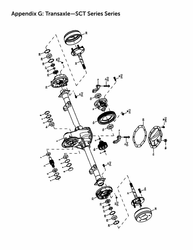
Appendix G: Transaxle—SCT Series Series
41
# Description Part Number Quantity
All Complete Tugger Transaxle, 32W 39156
3 Gear, Input See Kit 1
4 Ring, Retaining 14232 3
5 O-Ring 18057 3
6 Bearing, Ball 30087 1
7 Bearing, Ball 30011 1
8 Plug, End Cap 30013 2
9 Bearing, Ball 300091 2
10 Gear, Intermediate Assembly See Kit
11 O-Ring 30008 2
12 Gear, Final Drive See Kit
13 Bearing, Ball 30007 2
15 Screw, Cap 30088 4
16 Nut, Lock 30089 4
17 Plate, Cover 30014 1
18 Plug, Fill 30062 1
19 Screw, Cover Plate 30090 10
23 Brake Assembly, Left-Hand Shoe Type 36153 1
24 Brake Assembly, Right-Hand Shoe Type 36154 1
25 Oil Seal, Axle Shaft 30037 2
26 Ring, Retaining, Tugger 30038 2
27 Ring, Retaining, Wheel Bearing) 30039 4
28 Ring, Retaining, Tugger 30040 2
29 Bearing, Ball, Tugger 30041 2
30 Drum, Brake, 5 Lug Use Item 37 2
31 Shaft, Left-Hand Axle 5 Lug 30042 1
32 Shaft, Right-Hand Axle 5 Lug” 30044 1
Kit Tugger Gear Set (Includes#3, #10, #12 30045
37 Drum Assembly (5-lug) 30082
Kit Kit, Input, Shaft 12.44:1 Ration ( Includes #3, #4, #5, #6, #7) 30022
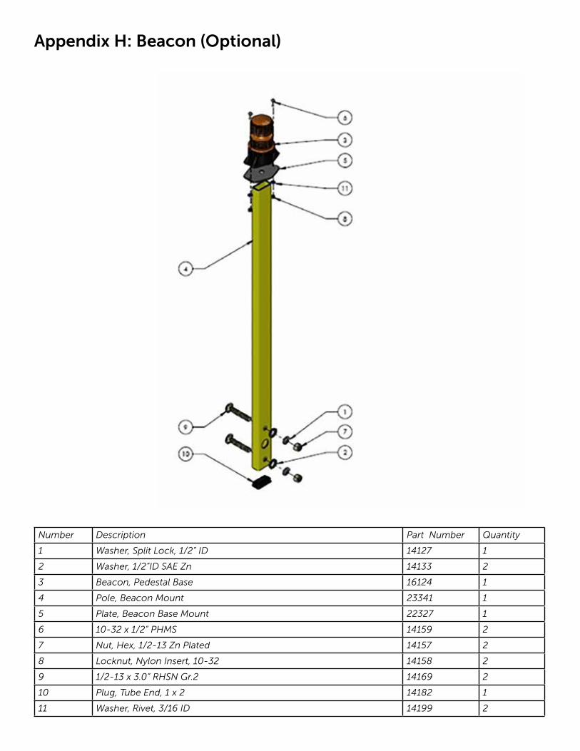
Appendix H: Beacon (Optional)
Number Description Part Number Quantity
1 Washer, Split Lock, 1/2” ID 14127 1
2 Washer, 1/2”ID SAE Zn 14133 2
3 Beacon, Pedestal Base 16124 1
4 Pole, Beacon Mount 23341 1
5 Plate, Beacon Base Mount 22327 1
6 10-32 x 1/2” PHMS 14159 2
7 Nut, Hex, 1/2-13 Zn Plated 14157 2
8 Locknut, Nylon Insert, 10-32 14158 2
9 1/2-13 x 3.0” RHSN Gr.2 14169 2
10 Plug, Tube End, 1 x 2 14182 1
11 Washer, Rivet, 3/16 ID 14199 2
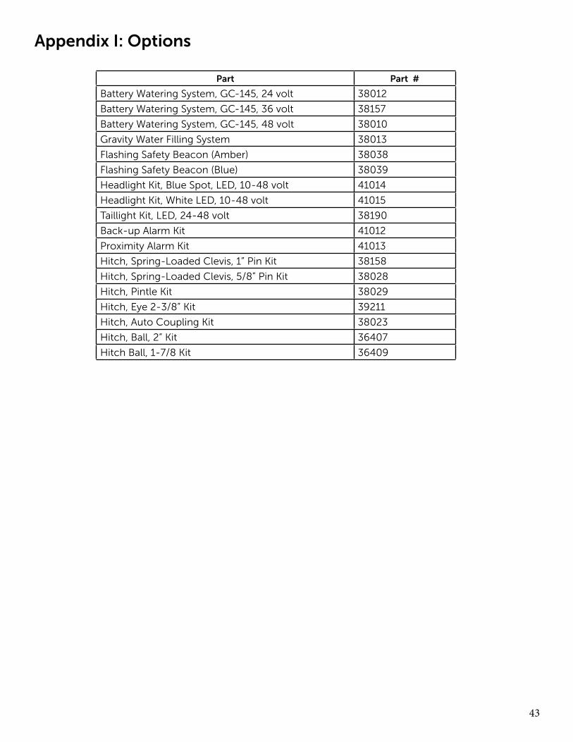
43
Part Part #
Battery Watering System, GC-145, 24 volt 38012
Battery Watering System, GC-145, 36 volt 38157
Battery Watering System, GC-145, 48 volt 38010
Gravity Water Filling System 38013
Flashing Safety Beacon (Amber) 38038
Flashing Safety Beacon (Blue) 38039
Headlight Kit, Blue Spot, LED, 10-48 volt 41014
Headlight Kit, White LED, 10-48 volt 41015
Taillight Kit, LED, 24-48 volt 38190
Back-up Alarm Kit 41012
Proximity Alarm Kit 41013
Hitch, Spring-Loaded Clevis, 1” Pin Kit 38158
Hitch, Spring-Loaded Clevis, 5/8” Pin Kit 38028
Hitch, Pintle Kit 38029
Hitch, Eye 2-3/8” Kit 39211
Hitch, Auto Coupling Kit 38023
Hitch, Ball, 2” Kit 36407
Hitch Ball, 1-7/8 Kit 36409
Appendix I: Options

44
The optional programmable code switch which pre-vents unauthorized use of the vehicle (part number 38206). The switch is installed in lieu of the standard switch to control access and operation of the vehi-cle within the customer’s premises. It can be factory installed or purchased separately to upgrade existing vehicles.
The switch allows plant and facility managers to input up to 99 dif-ferent users/drivers to track vehicle usage. If an accident occurs, or the vehicle is damaged, the manager can easily identify the last opera-tor. The switch also fea-tures an internal clock that records “on” hours and notifies the opera-tor when the 250-hour mark is reached.
Each user can se-lect a four-to eight digit personal access code and a separate supervisor user menu programs the unit. The switch will provide the last user ID code when prompted by the supervisor. Only users with active ID codes can operate the vehicle, virtually eliminating all unauthorized use.
The switch operates in a voltage range from 12 to 90 volts DC and is enclosed in an IP65 rated housing. Three internal LEDs indicate operational status - red indicates an error or lock mode and green indicates vehicle is active. The unit also provides user feedback with key beep and error tones. Amber indicates that the code is accepted.
Step-by-Step Programming Instructions:
First, log onto the Supervisor Mode. Press 0 0 1 2 3 4 ON. The “Accept” LED will acknowledge the entry and the red and amber LEDs will alternately flash to indicate you are in the Supervisor Mode and ready to enter a Supervisor Mode menu.
Note: As you enter each Supervisor Mode menu, the number of Red LED flashes will correspond to the menu number. For example, one Red LED flash for menu 1, two Red LED flashes for menu 2, etc.
.
Appendix J: Programming the KeypadSupervisor ModeThis mode is used to program user codes and set up advanced functions of the Programmable Code Switch. From this mode each key initiates a specific configuration procedure or function in the supervisor menu. These options are explained in the following sections.
Function 1 – User ProgrammingThe “1” key initiates user code programming mode. When you press the “1” key, the red “pro-gram” LED will begin flashing to indicate the unit has entered user code programming mode. To program a user code, follow the two step proce-dure below. Like the supervisor code, user codes must consist of four numerical digits and may not include “on” or “off” keys. If you wish to disable a user number, program its access code to 0000. All user numbers are disabled initially and remain disabled until programmed using this function. You may abort the entry procedure at any time and return to supervisor mode by pressing the “off” key.
1. Enter the two-digit user number. User num-bers must be two digits so those numbers less than 10 must be entered as “01”, “02”, etc. When you have entered a (valid) user number, the red “program” LED will stop flashing and stay on, indicating the unit is ready for you to
enter a new access code..2. Enter a four-digit user access code. Upon
completion of the entry of a valid access code, the amber “accept” LED will be illuminated for one long flash and then the unit will go back to supervisor mode.
Quick Steps – Function 11. While in supervisor mode press 1. Unit will in-
dicate Function 1 configuration mode active.2. Enter two-digit user number followed by
four-digit access code. Amber LED will indi-cate acceptance of code and unit will return to supervisor mode.
Function 2 – Last User IdentificationThe “2” key initiates the last user function. This function will tell you which user number was the last one to activate this unit. If the supervisor was the last one to turn on the output, then an error signal (short, then long tone) beep will sound and the unit will go back to supervisor mode.Otherwise, the unit will sound four short beeps to indicate the last user information is coming followed by a series of flashes of the red and/or amber LEDs. Each red flash counts as 10 and each amber flash counts as one. For example, if user 27 were the last one to activate the unit, you would
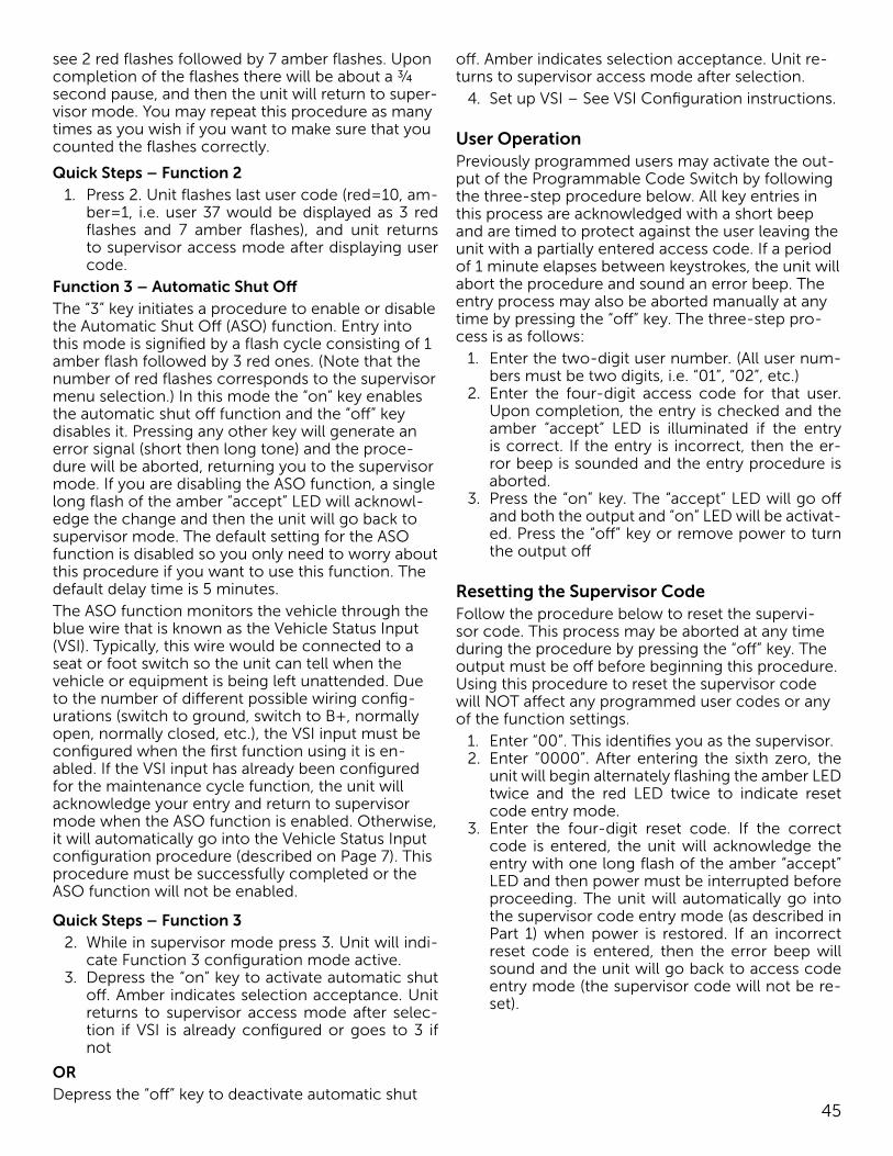
45
see 2 red flashes followed by 7 amber flashes. Upon completion of the flashes there will be about a ¾ second pause, and then the unit will return to super-visor mode. You may repeat this procedure as many times as you wish if you want to make sure that you counted the flashes correctly.
Quick Steps – Function 21. Press 2. Unit flashes last user code (red=10, am-
ber=1, i.e. user 37 would be displayed as 3 red flashes and 7 amber flashes), and unit returns to supervisor access mode after displaying user code.
Function 3 – Automatic Shut OffThe “3” key initiates a procedure to enable or disable the Automatic Shut Off (ASO) function. Entry into this mode is signified by a flash cycle consisting of 1 amber flash followed by 3 red ones. (Note that the number of red flashes corresponds to the supervisor menu selection.) In this mode the “on” key enables the automatic shut off function and the “off” key disables it. Pressing any other key will generate an error signal (short then long tone) and the proce-dure will be aborted, returning you to the supervisor mode. If you are disabling the ASO function, a single long flash of the amber “accept” LED will acknowl-edge the change and then the unit will go back to supervisor mode. The default setting for the ASO function is disabled so you only need to worry about this procedure if you want to use this function. The default delay time is 5 minutes. The ASO function monitors the vehicle through the blue wire that is known as the Vehicle Status Input (VSI). Typically, this wire would be connected to a seat or foot switch so the unit can tell when the vehicle or equipment is being left unattended. Due to the number of different possible wiring config-urations (switch to ground, switch to B+, normally open, normally closed, etc.), the VSI input must be configured when the first function using it is en-abled. If the VSI input has already been configured for the maintenance cycle function, the unit will acknowledge your entry and return to supervisor mode when the ASO function is enabled. Otherwise, it will automatically go into the Vehicle Status Input configuration procedure (described on Page 7). This procedure must be successfully completed or the ASO function will not be enabled.
Quick Steps – Function 32. While in supervisor mode press 3. Unit will indi-
cate Function 3 configuration mode active.3. Depress the “on” key to activate automatic shut
off. Amber indicates selection acceptance. Unit returns to supervisor access mode after selec-tion if VSI is already configured or goes to 3 if not
ORDepress the “off” key to deactivate automatic shut
off. Amber indicates selection acceptance. Unit re-turns to supervisor access mode after selection.
4. Set up VSI – See VSI Configuration instructions.
User OperationPreviously programmed users may activate the out-put of the Programmable Code Switch by following the three-step procedure below. All key entries in this process are acknowledged with a short beep and are timed to protect against the user leaving the unit with a partially entered access code. If a period of 1 minute elapses between keystrokes, the unit will abort the procedure and sound an error beep. The entry process may also be aborted manually at any time by pressing the “off” key. The three-step pro-cess is as follows:
1. Enter the two-digit user number. (All user num-bers must be two digits, i.e. “01”, “02”, etc.)
2. Enter the four-digit access code for that user. Upon completion, the entry is checked and the amber “accept” LED is illuminated if the entry is correct. If the entry is incorrect, then the er-ror beep is sounded and the entry procedure is aborted.
3. Press the “on” key. The “accept” LED will go off and both the output and “on” LED will be activat-ed. Press the “off” key or remove power to turn the output off
Resetting the Supervisor CodeFollow the procedure below to reset the supervi-sor code. This process may be aborted at any time during the procedure by pressing the “off” key. The output must be off before beginning this procedure. Using this procedure to reset the supervisor code will NOT affect any programmed user codes or any of the function settings.
1. Enter “00”. This identifies you as the supervisor.2. Enter “0000”. After entering the sixth zero, the
unit will begin alternately flashing the amber LED twice and the red LED twice to indicate reset code entry mode.
3. Enter the four-digit reset code. If the correct code is entered, the unit will acknowledge the entry with one long flash of the amber “accept” LED and then power must be interrupted before proceeding. The unit will automatically go into the supervisor code entry mode (as described in Part 1) when power is restored. If an incorrect reset code is entered, then the error beep will sound and the unit will go back to access code entry mode (the supervisor code will not be re-set).
46
VSI (Vehicle Status Input) ConfigurationAs mentioned earlier, the Vehicle Status Input (VSI) must be configured before enabling the Auto Shut Off (ASO) function or setting the Maintenance Cycle (MC) function for external control. Both functions may use the VSI input at the same time, but the input will remain in the configuration that was set when it was first activated. If both functions are deactivated at the same time, the input will have to be configured again to use it. The VSI configuration procedure is automatically triggered when needed and cannot be initiated manually. If you change wir-ing and need to reconfigure the input, disable ASO and set the MC control to internal then set them back to force a new configuration. The VSI configu-ration procedure is a two-step process. This proce-dure allows the input to be flexible enough for use in a number of different types of applications and wiring configurations.
1. The unit will indicate entry into this procedure by repeating a display cycle that consists of 2 amber flashes, 1 red flash, 1 amber flash and a pause. If the signal you are monitoring is pow-ered by the Programmable Code Switch out-put, you may turn the output on temporarily by pressing the “on” key. Move the switch or other VSI input to the position or setting it will be at when you want the unit to consider the input to be active. For example, if you are using a seat switch, then you should sit on the seat. When you are sure the input is in the active state, press any numerical key. The unit will read and store the input, then acknowledge it with a long flash of the amber “accept” LED. You may also abort the configuration procedure by pressing the “off” key if you notice that something isn’t right.
2. After an acknowledge flash the display cycle will change to 3 amber flashes, 1 red flash, 1 am-ber flash and a pause. At that point you need to change the switch or setting to the inactive po-sition (in the previous example you would get off of the seat). When you are sure the input is inactive, press a numerical key. This will prompt the unit to again read the input. If the unit can
detect a difference between the two states, an-other acknowledge flash of the “accept” LED will be displayed and then the unit will return to supervisor mode. If the unit can not detect a difference between the two settings, then an er-ror signal (short then long tone) will be sounded and the process will be aborted (including the setting change you were making) and the unit will return to supervisor mode. If the output was turned on in step one; it will automatically go off upon completion on this procedure.
Note: If you are having trouble getting the VSI input to configure properly, consider the following: The VSI input is designed to detect three states: con-nected to ground, connected to the positive supply voltage (B+) or open (not connected to anything). You may use any combination of those three. The VSI input is not designed to detect voltage level changes within the supply range. Check the wiring to make sure the input is being driven (or released) into a different one of the three states listed for the active and inactive set- tings. Many vehicles draw power for such switches from the “key switch” line, so you may need to turn the Programmable Code Switch on during configuration. If the problem still persists, please call for assistance.
Quick Steps – VSI (Vehicle Status Input)1. Unit flashes 2 amber flashes, 1 red flash, 1 amber
flash and a pause to indicate unit is ready to re-ceive vehicle input.
2. Apply vehicle active signal to blue wire. If this requires the Programmable Code Switch output to be on, press the “on” key.
3. Press any numerical key (0-9). Amber LED indi-cates acceptance of active input.
4. Unit then flashes 3 amber flashes, 1 red flash, 1 amber flash and a pause to indicate unit is ready to receive vehicle inactive input.
5. Apply vehicle inactive signal to blue wire.6. Press any numerical key (0-9). Amber LED indi-
cates acceptance of inactive input. Unit returns to supervisor access mode after inactive input is accepted. If the output was turned on, it will go back off.
Acceptable VSI Input States
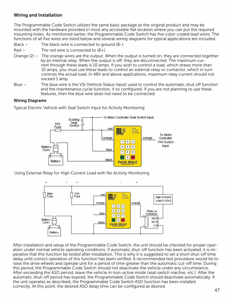
47
Wiring and Installation
The Programmable Code Switch utilizes the same basic package as the original product and may be mounted with the hardware provided in most any accessible flat location where you can put the required mounting holes. As mentioned earlier, the Programmable Code Switch has five color-coded lead wires. The functions of all five wires are listed below and several wiring diagrams for typical applications are included.Black – The black wire is connected to ground (B-).Red – The red wire is connected to (B+).Orange (2) – The orange wires are the output. When the output is turned on, they are connected together
by an internal relay. When the output is off, they are disconnected. The maximum cur-rent through these leads is 10 amps. If you wish to control a load, which draws more than 10 amps, you must use these leads to control an external relay or contactor, which in turn controls the actual load. In 48V and above applications, maximum relay current should not exceed 1 amp.
Blue – The blue wire is the VSI (Vehicle Status Input) used to control the automatic shut off function and the maintenance cycle function, if so configured. If you are not planning to use these features, then the blue wire does not need to be connected.
Wiring Diagrams
Typical Electric Vehicle with Seat Switch Input for Activity Monitoring
Using External Relay for High Current Load with No Activity Monitoring
After installation and setup of the Programmable Code Switch, the unit should be checked for proper oper-ation under normal vehicle operating conditions. If automatic shut-off function has been activated, it is im-perative that this function be tested after installation. This is why it is suggested to set a short shut-off time delay until correct operation of this function has been verified. A recommended test procedure would be to raise the drive wheels and operate unit for a period of time greater than the automatic cut-off time. During this period, the Programmable Code Switch should not deactivate the vehicle under any circumstance. After exceeding the ASO period, leave the vehicle in non-active mode (seat switch inactive, etc.). After the automatic shut-off period has expired, the Programmable Code Switch should deactivate automatically. If the unit operates as described, the Programmable Code Switch ASO function has been installedcorrectly. At this point, the desired ASO delay time can be configured as desired.

Pack Mule Electric Vehicles are products of Wesley International, LLC
3680 Chestnut Street • Scottdale, GA 30079 • Phone (404) 292-7441 • Toll Free (800) 241-2869 • Fax (404) 292-8469
[email protected] • www.wesleyinternational.com
JFMBGB012418