Embed Size (px)
Citation preview
ELECTRIC CHAIN HOIST ER2 and NER2
SERIES 1/8 Ton through 5 Ton Capacity
EFFECTIVE: October 15, 2018
Code, Lot and Serial Number
This equipment should not be installed, operated, or maintained by any person who has not read and understood all the contents of this manual. Failure to read and comply with the contents of this manual can result in serious bodily injury or death, and/or property damage.
2
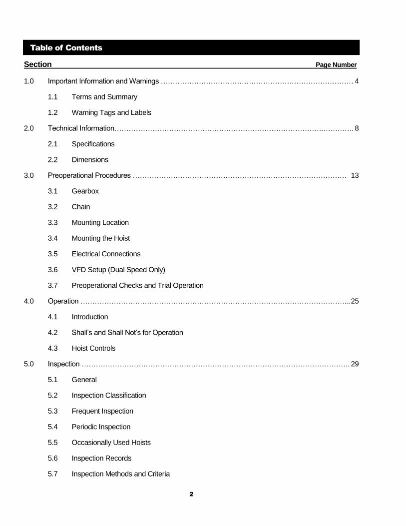
Table of Contents
Section Page Number
1.0 Important Information and Warnings ……………………………………………………………………… 4
1.1 Terms and Summary
1.2 Warning Tags and Labels
2.0 Technical Information…………………………………………………………………………….…………. 8
2.1 Specifications
2.2 Dimensions
3.0 Preoperational Procedures ……………………………………………………………………………… 13
3.1 Gearbox
3.2 Chain
3.3 Mounting Location
3.4 Mounting the Hoist
3.5 Electrical Connections
3.6 VFD Setup (Dual Speed Only)
3.7 Preoperational Checks and Trial Operation
4.0 Operation …………………………………………………………………………………………………... 25
4.1 Introduction
4.2 Shall’s and Shall Not’s for Operation
4.3 Hoist Controls
5.0 Inspection ………………………………………………………………………………………………….. 29
5.1 General
5.2 Inspection Classification
5.3 Frequent Inspection
5.4 Periodic Inspection
5.5 Occasionally Used Hoists
5.6 Inspection Records
5.7 Inspection Methods and Criteria
3
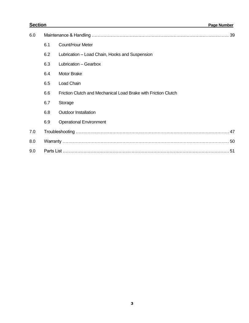
Section Page Number
6.0 Maintenance & Handling …………………………………………………………………………………. 39
6.1 Count/Hour Meter
6.2 Lubrication – Load Chain, Hooks and Suspension
6.3 Lubrication – Gearbox
6.4 Motor Brake
6.5 Load Chain
6.6 Friction Clutch and Mechanical Load Brake with Friction Clutch
6.7 Storage
6.8 Outdoor Installation
6.9 Operational Environment
7.0 Troubleshooting …………………………………………………………………………………………… 47
8.0 Warranty …………………………………………………………………………………………………… 50
9.0 Parts List …………………………………………………………………………………………………… 51
4
1.0 Important Information and Warnings
1.1 Terms and Summary
This manual provides important information for personnel involved with the installation, operation and maintenance of this product. Although you may be familiar with this or similar equipment, it is strongly recommended that you read this manual before installing, operating or maintaining the product.
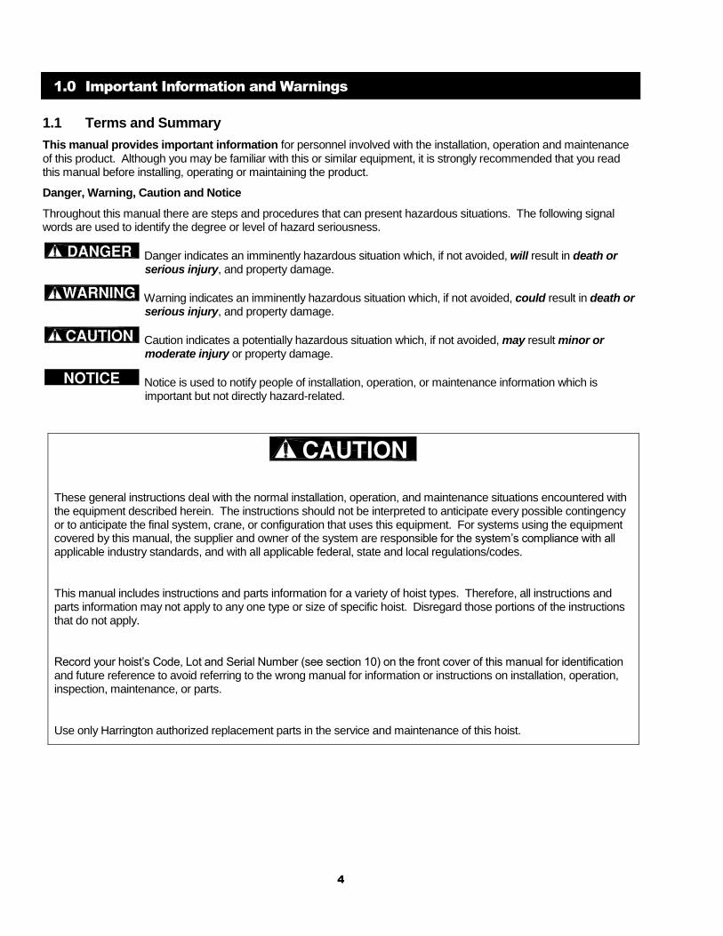
Danger, Warning, Caution and Notice
Throughout this manual there are steps and procedures that can present hazardous situations. The following signal words are used to identify the degree or level of hazard seriousness.
Danger indicates an imminently hazardous situation which, if not avoided, will result in death or serious injury, and property damage.
Warning indicates an imminently hazardous situation which, if not avoided, could result in death or serious injury, and property damage.
Caution indicates a potentially hazardous situation which, if not avoided, may result minor or moderate injury or property damage.
Notice is used to notify people of installation, operation, or maintenance information which is important but not directly hazard-related.
These general instructions deal with the normal installation, operation, and maintenance situations encountered with the equipment described herein. The instructions should not be interpreted to anticipate every possible contingency or to anticipate the final system, crane, or configuration that uses this equipment. For systems using the equipment covered by this manual, the supplier and owner of the system are responsible for the system’s compliance with all applicable industry standards, and with all applicable federal, state and local regulations/codes.
This manual includes instructions and parts information for a variety of hoist types. Therefore, all instructions and parts information may not apply to any one type or size of specific hoist. Disregard those portions of the instructions that do not apply.
Record your hoist’s Code, Lot and Serial Number (see section 10) on the front cover of this manual for identification and future reference to avoid referring to the wrong manual for information or instructions on installation, operation, inspection, maintenance, or parts.
Use only Harrington authorized replacement parts in the service and maintenance of this hoist.
5
Equipment described herein is not designed for and MUST NOT be used for lifting, supporting, or transporting people, or for lifting or supporting loads over people.
Equipment described herein should not be used in conjunction with other equipment unless necessary and/or required safety devices applicable to the system, crane, or application are installed by the system designer, system manufacturer, crane manufacturer, installer, or user.
Modifications to upgrade, rerate, or otherwise alter this equipment shall be authorized only by the original equipment manufacturer.
Equipment described herein may be used in the design and manufacture of cranes or monorails. Additional equipment or devices may be required for the crane and monorail to comply with applicable crane design and safety standards. The crane designer, crane manufacturer, or user is responsible to furnish these additional items for compliance. Refer to ANSI/ASME B30.17, “Safety Standard for Top-Running Single Girder Cranes”; ANSI/ASME B30.2 “Safety Standard for Top-Running Double-Girder Cranes”; and ANSI/ASME B30.11 “Safety Standard for Underhung Cranes and Monorails”.
If a below-the-hook lifting device or sling is used with a hoist, refer to ANSI/ASME B30.9, “Safety Standard for Slings” or ANSI/ASME B30.20, “Safety Standard for Below-the-Hook Lifting Devices”.
Hoists and cranes, used to handle hot molten material may require additional equipment or devices. Refer to ANSI Z241.2, “Safety Requirements for Melting and Pouring of Metals in the Metal Casting Industry”.
Electrical equipment described herein is designed and built in compliance with Harrington's interpretation of ANSI/NFPA 70, “National Electrical Code”. The system designer, system manufacturer, crane designer, crane manufacturer, installer, or user is responsible to assure that the installation and associated wiring of these electrical components is in compliance with ANSI/NFPA 70, and all applicable Federal, State and Local Codes.
Failure to read and comply with any one of the limitations noted herein can result in serious bodily injury or death, and/or property damage.
6
HAZARDOUS VOLTAGES ARE PRESENT IN THE CONTROL BOX, OTHER ELECTRICAL COMPONENTS, AND CONNECTIONS BETWEEN THESE COMPONENTS.
Before performing ANY mechanical or electrical maintenance on the equipment, de-energize (disconnect) the main switch supplying power to the equipment; as well as lock and tag the main switch in the de-energized position. Refer to ANSI Z244.1, “Personnel Protection – Lockout/Tagout of Energy Sources”.
Dual speed units incorporate a VFD as well as a Capacitor. Therefore, DO NOT perform ANY mechanical or electrical maintenance within 5 minutes of powering down to allow time for the capacitor inside the VFD to discharge. DO NOT perform any voltage or insulation resistance tests with a meg ohmmeter when the VFD is connected to the electrical circuit.
Only trained and competent personnel should inspect and repair this equipment.
It is the responsibility of the owner/user to install, inspect, test, maintain, and operate a hoist in accordance with ANSI/ASME B30.16, “Safety Standard for Overhead Hoists”, OSHA Regulations and ANSI/NFPA 70, National Electric Code. If the hoist is installed as part of a total lifting system, such as an overhead crane or monorail, it is also the responsibility of the owner/user to comply with the applicable ANSI/ASME B30 volume that addresses that type of equipment.
It is the responsibility of the owner/user to have all personnel that will install, inspect, test, maintain, and operate a hoist read the contents of this manual and applicable portions of ANSI/ASME B30.16, “Safety Standard for Overhead Hoists”, OSHA Regulations and ANSI/NFPA 70, “National Electric Code”. If the hoist is installed as part of a total lifting system, such as an overhead crane, the applicable ANSI/ASME B30 volume that addresses that type of equipment must also be read by all personnel.
If the hoist owner/user requires additional information, or if any information in the manual is not clear, contact Harrington or the distributor of the hoist. Do not install, inspect, test, maintain, or operate this hoist unless this information is fully understood.
A regular schedule of inspection of the hoist in accordance with the requirements of ANSI/ASME B30.16 should be established and records maintained.
7
1.2 Warning Tags and Labels
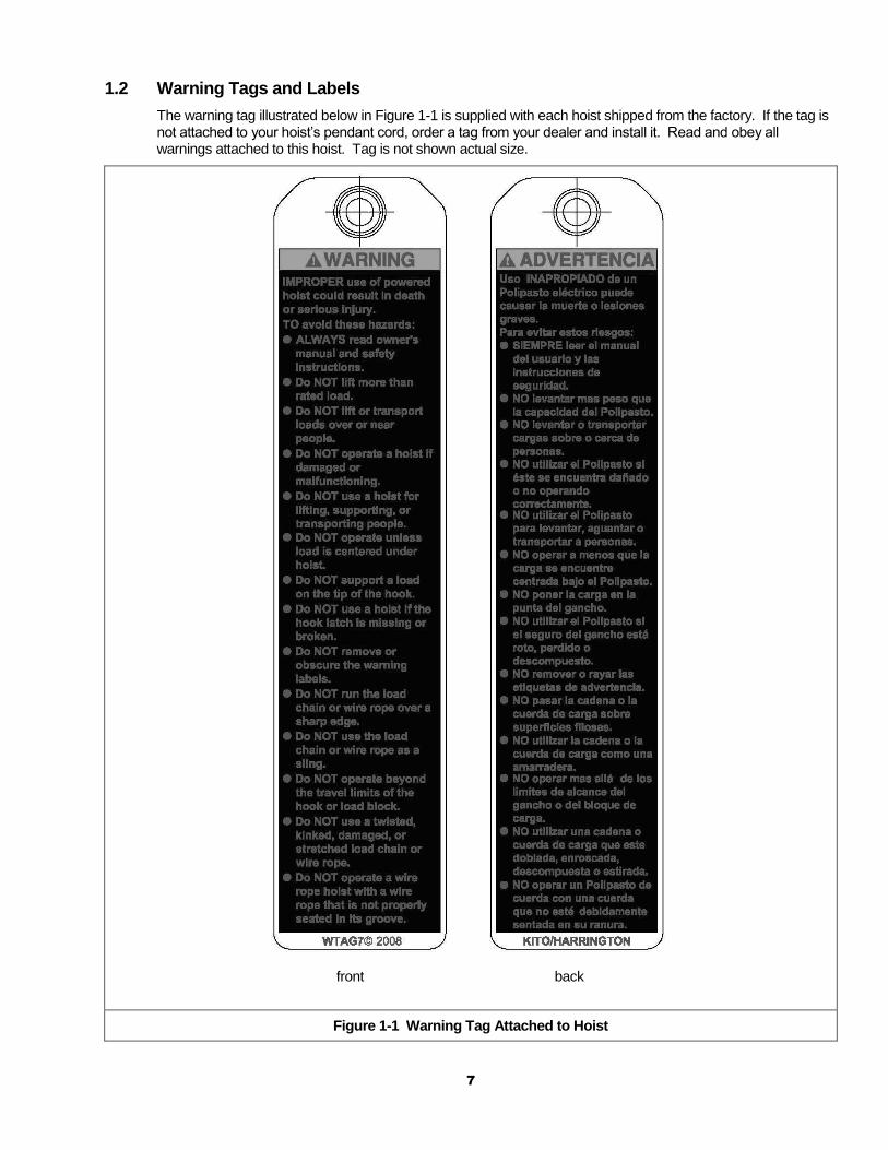
The warning tag illustrated below in Figure 1-1 is supplied with each hoist shipped from the factory. If the tag is not attached to your hoist’s pendant cord, order a tag from your dealer and install it. Read and obey all warnings attached to this hoist. Tag is not shown actual size.
front back
Figure 1-1 Warning Tag Attached to Hoist
8
2.0 Technical Information
2.1 Specifications
Note: This Owners Manual is for the Enhanced Features Model ER and NER. This Enhanced Features Model is referred to as the ER2 and NER2 in this Owners Manual.
Pendants are shown with optional Emergency Stop button.
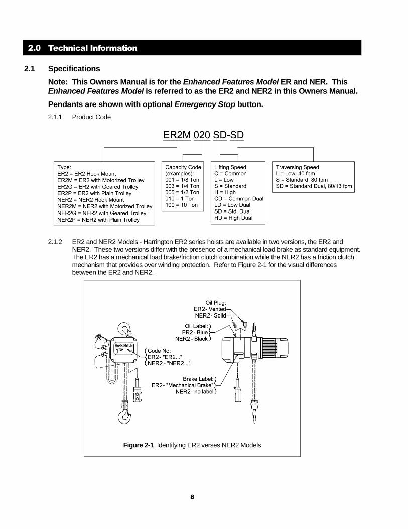
2.1.1 Product Code
2.1.2 ER2 and NER2 Models - Harrington ER2 series hoists are available in two versions, the ER2 and NER2. These two versions differ with the presence of a mechanical load brake as standard equipment. The ER2 has a mechanical load brake/friction clutch combination while the NER2 has a friction clutch mechanism that provides over winding protection. Refer to Figure 2-1 for the visual differences between the ER2 and NER2.
Figure 2-1 Identifying ER2 verses NER2 Models
9
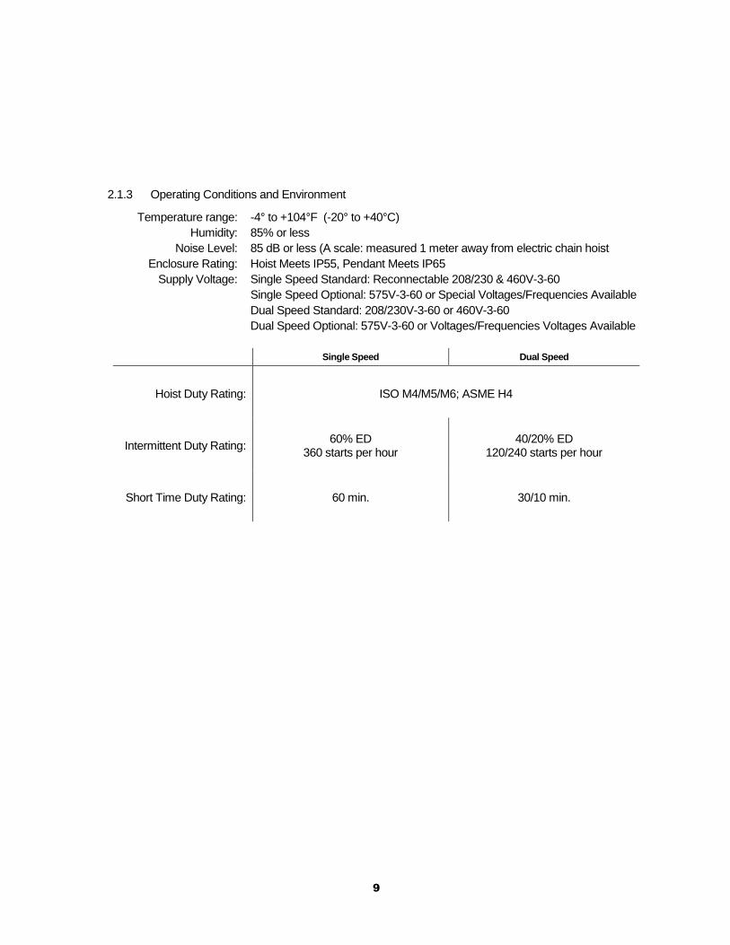
2.1.3 Operating Conditions and Environment
Temperature range: -4° to +104°F (-20° to +40°C)
Humidity: 85% or less
Noise Level: 85 dB or less (A scale: measured 1 meter away from electric chain hoist
Enclosure Rating: Hoist Meets IP55, Pendant Meets IP65
Supply Voltage: Single Speed Standard: Reconnectable 208/230 & 460V-3-60
Single Speed Optional: 575V-3-60 or Special Voltages/Frequencies Available
Dual Speed Standard: 208/230V-3-60 or 460V-3-60
Dual Speed Optional: 575V-3-60 or Voltages/Frequencies Voltages Available
Single Speed Dual Speed
Hoist Duty Rating:
ISO M4/M5/M6; ASME H4
Intermittent Duty Rating:
60% ED 360 starts per hour
40/20% ED 120/240 starts per hour
Short Time Duty Rating:
60 min. 30/10 min.
10
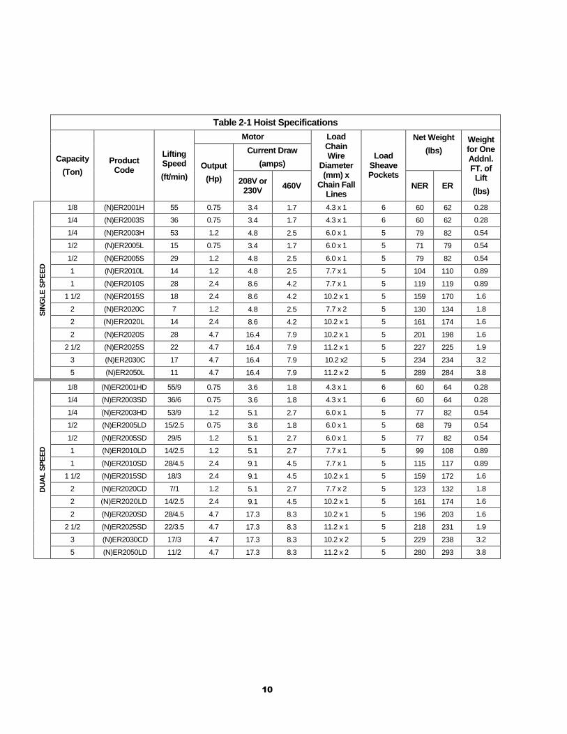
Table 2-1 Hoist Specifications
Capacity
(Ton)
Product Code
Lifting Speed
(ft/min)
Motor Load Chain Wire
Diameter (mm) x
Chain Fall Lines
Load Sheave Pockets
Net Weight
(lbs)
Weight for One Addnl. FT. of
Lift
(lbs)
Output
(Hp)
Current Draw
(amps)
208V or 230V
460V NER ER
SIN
GL
E S
PE
ED
1/8 (N)ER2001H 55 0.75 3.4 1.7 4.3 x 1 6 60 62 0.28
1/4 (N)ER2003S 36 0.75 3.4 1.7 4.3 x 1 6 60 62 0.28
1/4 (N)ER2003H 53 1.2 4.8 2.5 6.0 x 1 5 79 82 0.54
1/2 (N)ER2005L 15 0.75 3.4 1.7 6.0 x 1 5 71 79 0.54
1/2 (N)ER2005S 29 1.2 4.8 2.5 6.0 x 1 5 79 82 0.54
1 (N)ER2010L 14 1.2 4.8 2.5 7.7 x 1 5 104 110 0.89
1 (N)ER2010S 28 2.4 8.6 4.2 7.7 x 1 5 119 119 0.89
1 1/2 (N)ER2015S 18 2.4 8.6 4.2 10.2 x 1 5 159 170 1.6
2 (N)ER2020C 7 1.2 4.8 2.5 7.7 x 2 5 130 134 1.8
2 (N)ER2020L 14 2.4 8.6 4.2 10.2 x 1 5 161 174 1.6
2 (N)ER2020S 28 4.7 16.4 7.9 10.2 x 1 5 201 198 1.6
2 1/2 (N)ER2025S 22 4.7 16.4 7.9 11.2 x 1 5 227 225 1.9
3 (N)ER2030C 17 4.7 16.4 7.9 10.2 x2 5 234 234 3.2
5 (N)ER2050L 11 4.7 16.4 7.9 11.2 x 2 5 289 284 3.8
DU
AL
SP
EE
D
1/8 (N)ER2001HD 55/9 0.75 3.6 1.8 4.3 x 1 6 60 64 0.28
1/4 (N)ER2003SD 36/6 0.75 3.6 1.8 4.3 x 1 6 60 64 0.28
1/4 (N)ER2003HD 53/9 1.2 5.1 2.7 6.0 x 1 5 77 82 0.54
1/2 (N)ER2005LD 15/2.5 0.75 3.6 1.8 6.0 x 1 5 68 79 0.54
1/2 (N)ER2005SD 29/5 1.2 5.1 2.7 6.0 x 1 5 77 82 0.54
1 (N)ER2010LD 14/2.5 1.2 5.1 2.7 7.7 x 1 5 99 108 0.89
1 (N)ER2010SD 28/4.5 2.4 9.1 4.5 7.7 x 1 5 115 117 0.89
1 1/2 (N)ER2015SD 18/3 2.4 9.1 4.5 10.2 x 1 5 159 172 1.6
2 (N)ER2020CD 7/1 1.2 5.1 2.7 7.7 x 2 5 123 132 1.8
2 (N)ER2020LD 14/2.5 2.4 9.1 4.5 10.2 x 1 5 161 174 1.6
2 (N)ER2020SD 28/4.5 4.7 17.3 8.3 10.2 x 1 5 196 203 1.6
2 1/2 (N)ER2025SD 22/3.5 4.7 17.3 8.3 11.2 x 1 5 218 231 1.9
3 (N)ER2030CD 17/3 4.7 17.3 8.3 10.2 x 2 5 229 238 3.2
5 (N)ER2050LD 11/2 4.7 17.3 8.3 11.2 x 2 5 280 293 3.8
11
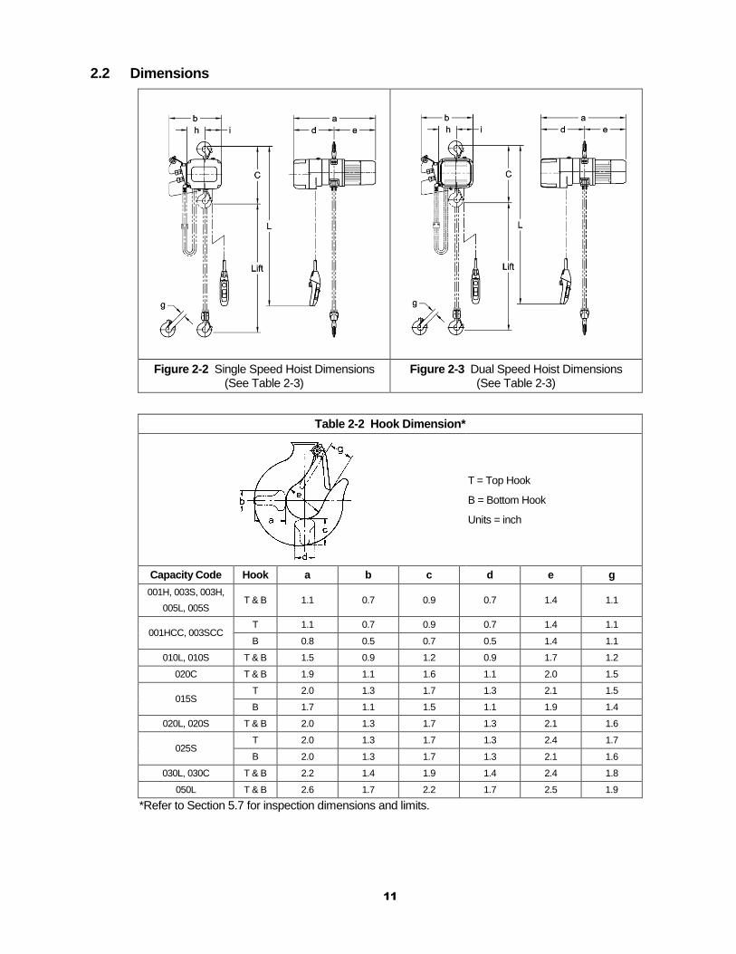
2.2 Dimensions
Figure 2-2 Single Speed Hoist Dimensions (See Table 2-3)
Figure 2-3 Dual Speed Hoist Dimensions (See Table 2-3)
Table 2-2 Hook Dimension*
T = Top Hook
B = Bottom Hook
Units = inch
Capacity Code Hook a b c d e g
001H, 003S, 003H,
005L, 005S T & B 1.1 0.7 0.9 0.7 1.4 1.1
001HCC, 003SCC T 1.1 0.7 0.9 0.7 1.4 1.1
B 0.8 0.5 0.7 0.5 1.4 1.1
010L, 010S T & B 1.5 0.9 1.2 0.9 1.7 1.2
020C T & B 1.9 1.1 1.6 1.1 2.0 1.5
015S T 2.0 1.3 1.7 1.3 2.1 1.5
B 1.7 1.1 1.5 1.1 1.9 1.4
020L, 020S T & B 2.0 1.3 1.7 1.3 2.1 1.6
025S T 2.0 1.3 1.7 1.3 2.4 1.7
B 2.0 1.3 1.7 1.3 2.1 1.6
030L, 030C T & B 2.2 1.4 1.9 1.4 2.4 1.8
050L T & B 2.6 1.7 2.2 1.7 2.5 1.9
*Refer to Section 5.7 for inspection dimensions and limits.
12
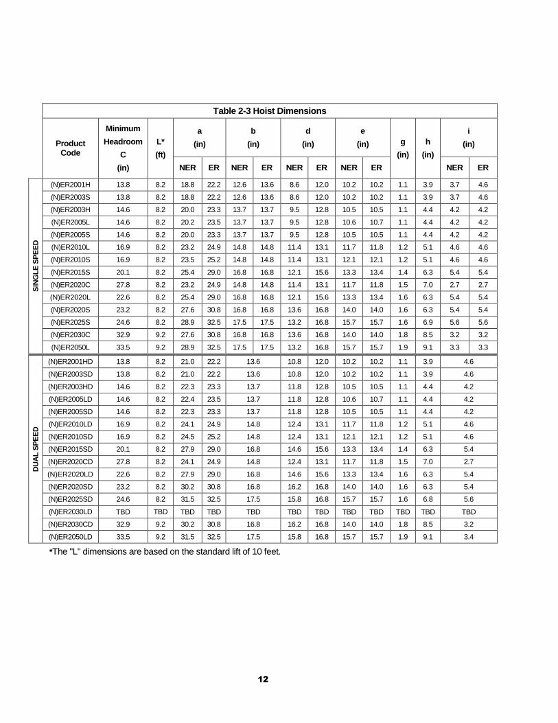
Table 2-3 Hoist Dimensions
Product
Code
Minimum
Headroom
C
(in)
L*
(ft)
a
(in)
b
(in)
d
(in)
e
(in) g
(in)
h
(in)
i
(in)
NER ER NER ER NER ER NER ER NER ER
SIN
GL
E S
PE
ED
(N)ER2001H 13.8 8.2 18.8 22.2 12.6 13.6 8.6 12.0 10.2 10.2 1.1 3.9 3.7 4.6
(N)ER2003S 13.8 8.2 18.8 22.2 12.6 13.6 8.6 12.0 10.2 10.2 1.1 3.9 3.7 4.6
(N)ER2003H 14.6 8.2 20.0 23.3 13.7 13.7 9.5 12.8 10.5 10.5 1.1 4.4 4.2 4.2
(N)ER2005L 14.6 8.2 20.2 23.5 13.7 13.7 9.5 12.8 10.6 10.7 1.1 4.4 4.2 4.2
(N)ER2005S 14.6 8.2 20.0 23.3 13.7 13.7 9.5 12.8 10.5 10.5 1.1 4.4 4.2 4.2
(N)ER2010L 16.9 8.2 23.2 24.9 14.8 14.8 11.4 13.1 11.7 11.8 1.2 5.1 4.6 4.6
(N)ER2010S 16.9 8.2 23.5 25.2 14.8 14.8 11.4 13.1 12.1 12.1 1.2 5.1 4.6 4.6
(N)ER2015S 20.1 8.2 25.4 29.0 16.8 16.8 12.1 15.6 13.3 13.4 1.4 6.3 5.4 5.4
(N)ER2020C 27.8 8.2 23.2 24.9 14.8 14.8 11.4 13.1 11.7 11.8 1.5 7.0 2.7 2.7
(N)ER2020L 22.6 8.2 25.4 29.0 16.8 16.8 12.1 15.6 13.3 13.4 1.6 6.3 5.4 5.4
(N)ER2020S 23.2 8.2 27.6 30.8 16.8 16.8 13.6 16.8 14.0 14.0 1.6 6.3 5.4 5.4
(N)ER2025S 24.6 8.2 28.9 32.5 17.5 17.5 13.2 16.8 15.7 15.7 1.6 6.9 5.6 5.6
(N)ER2030C 32.9 9.2 27.6 30.8 16.8 16.8 13.6 16.8 14.0 14.0 1.8 8.5 3.2 3.2
(N)ER2050L 33.5 9.2 28.9 32.5 17.5 17.5 13.2 16.8 15.7 15.7 1.9 9.1 3.3 3.3
DU
AL
SP
EE
D
(N)ER2001HD 13.8 8.2 21.0 22.2 13.6 10.8 12.0 10.2 10.2 1.1 3.9 4.6
(N)ER2003SD 13.8 8.2 21.0 22.2 13.6 10.8 12.0 10.2 10.2 1.1 3.9 4.6
(N)ER2003HD 14.6 8.2 22.3 23.3 13.7 11.8 12.8 10.5 10.5 1.1 4.4 4.2
(N)ER2005LD 14.6 8.2 22.4 23.5 13.7 11.8 12.8 10.6 10.7 1.1 4.4 4.2
(N)ER2005SD 14.6 8.2 22.3 23.3 13.7 11.8 12.8 10.5 10.5 1.1 4.4 4.2
(N)ER2010LD 16.9 8.2 24.1 24.9 14.8 12.4 13.1 11.7 11.8 1.2 5.1 4.6
(N)ER2010SD 16.9 8.2 24.5 25.2 14.8 12.4 13.1 12.1 12.1 1.2 5.1 4.6
(N)ER2015SD 20.1 8.2 27.9 29.0 16.8 14.6 15.6 13.3 13.4 1.4 6.3 5.4
(N)ER2020CD 27.8 8.2 24.1 24.9 14.8 12.4 13.1 11.7 11.8 1.5 7.0 2.7
(N)ER2020LD 22.6 8.2 27.9 29.0 16.8 14.6 15.6 13.3 13.4 1.6 6.3 5.4
(N)ER2020SD 23.2 8.2 30.2 30.8 16.8 16.2 16.8 14.0 14.0 1.6 6.3 5.4
(N)ER2025SD 24.6 8.2 31.5 32.5 17.5 15.8 16.8 15.7 15.7 1.6 6.8 5.6
(N)ER2030LD TBD TBD TBD TBD TBD TBD TBD TBD TBD TBD TBD TBD
(N)ER2030CD 32.9 9.2 30.2 30.8 16.8 16.2 16.8 14.0 14.0 1.8 8.5 3.2
(N)ER2050LD 33.5 9.2 31.5 32.5 17.5 15.8 16.8 15.7 15.7 1.9 9.1 3.4
*The "L" dimensions are based on the standard lift of 10 feet.
13
3.0 Preoperational Procedures
3.1 Gearbox
3.1.1 The gearbox is filled with the correct amount of oil at the time of shipment. The oil level must be verified prior to operation. The ER2 and NER2 hoists have different checking procedures. Refer to Section 6.3 for specific checking procedures.
3.1.2 Refer to Section 6.3 when replacing the gear oil.
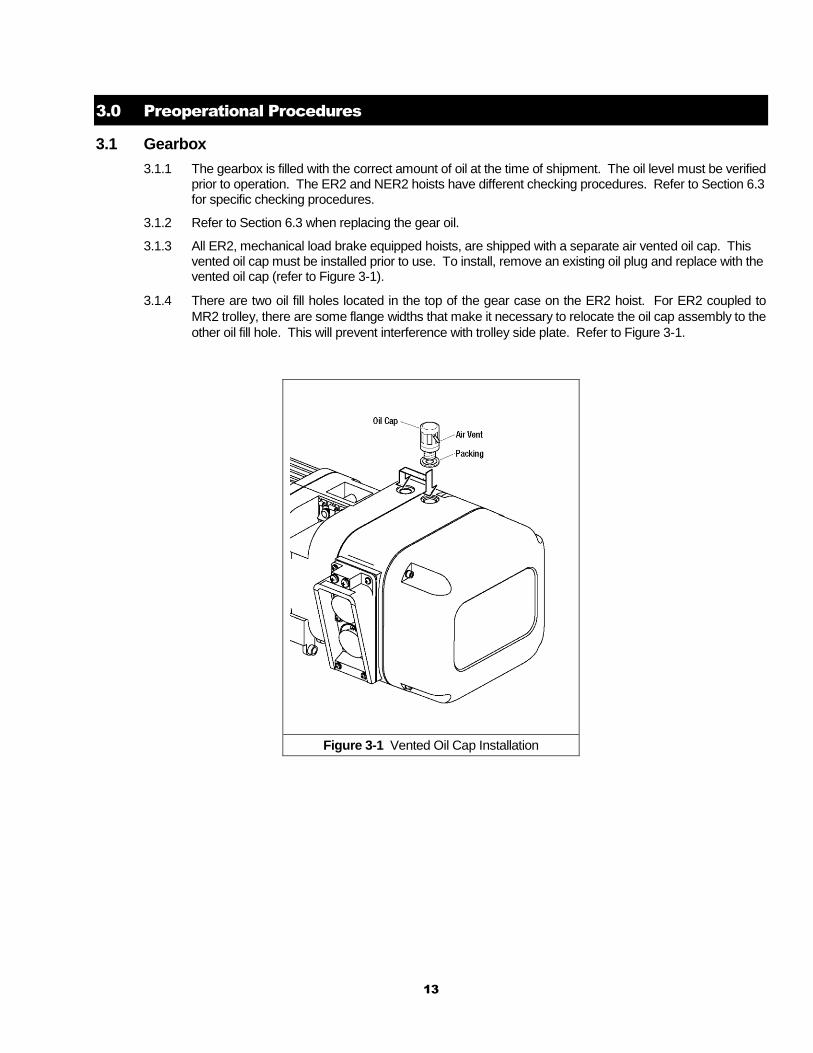
3.1.3 All ER2, mechanical load brake equipped hoists, are shipped with a separate air vented oil cap. This vented oil cap must be installed prior to use. To install, remove an existing oil plug and replace with the vented oil cap (refer to Figure 3-1).
3.1.4 There are two oil fill holes located in the top of the gear case on the ER2 hoist. For ER2 coupled to
MR2 trolley, there are some flange widths that make it necessary to relocate the oil cap assembly to the
other oil fill hole. This will prevent interference with trolley side plate. Refer to Figure 3-1.
Figure 3-1 Vented Oil Cap Installation
14
3.2 Chain
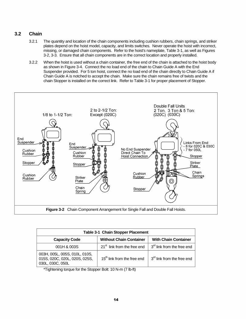
3.2.1 The quantity and location of the chain components including cushion rubbers, chain springs, and striker plates depend on the hoist model, capacity, and limits switches. Never operate the hoist with incorrect, missing, or damaged chain components. Refer to the hoist's nameplate, Table 3-1, as well as Figures 3-2, 3-3. Ensure that all chain components are in the correct location and properly installed.
3.2.2 When the hoist is used without a chain container, the free end of the chain is attached to the hoist body as shown in Figure 3-4. Connect the no load end of the chain to Chain Guide A with the End Suspender provided. For 5 ton hoist, connect the no load end of the chain directly to Chain Guide A if Chain Guide A is notched to accept the chain. Make sure the chain remains free of twists and the chain Stopper is installed on the correct link. Refer to Table 3-1 for proper placement of Stopper.
Figure 3-2 Chain Component Arrangement for Single Fall and Double Fall Hoists.
Table 3-1 Chain Stopper Placement
Capacity Code Without Chain Container With Chain Container
001H & 003S 21st link from the free end 3
rd link from the free end
003H, 005L, 005S, 010L, 010S, 015S, 020C, 020L, 020S, 025S, 030L, 030C, 050L
15th link from the free end 3
rd link from the free end
*Tightening torque for the Stopper Bolt: 10 N-m (7 lb-ft)
15
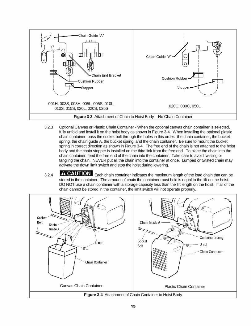
001H, 003S, 003H, 005L, 005S, 010L, 010S, 015S, 020L, 020S, 025S
020C, 030C, 050L
Figure 3-3 Attachment of Chain to Hoist Body – No Chain Container
3.2.3 Optional Canvas or Plastic Chain Container - When the optional canvas chain container is selected,
fully unfold and install it on the hoist body as shown in Figure 3-4. When installing the optional plastic chain container, pass the socket bolt through the holes in this order: the chain container, the bucket spring, the chain guide A, the bucket spring, and the chain container. Be sure to mount the bucket spring in correct direction as shown in Figure 3-4. The free end of the chain is not attached to the hoist body and the chain stopper is installed on the third link from the free end. To place the chain into the chain container, feed the free end of the chain into the container. Take care to avoid twisting or tangling the chain. NEVER put all the chain into the container at once. Lumped or twisted chain may activate the down limit switch and stop the hoist during lowering.
3.2.4 Each chain container indicates the maximum length of the load chain that can be stored in the container. The amount of chain the container must hold is equal to the lift on the hoist. DO NOT use a chain container with a storage capacity less than the lift length on the hoist. If all of the chain cannot be stored in the container, the limit switch will not operate properly.
Canvas Chain Container
Plastic Chain Container
Figure 3-4 Attachment of Chain Container to Hoist Body
16
3.2.5 When using an optional steel chain container, refer to the assembly drawing and instructions provided with the container for correct assembly and attachment.
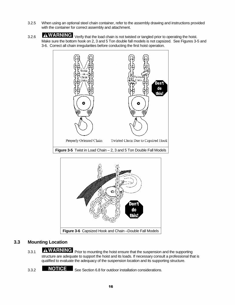
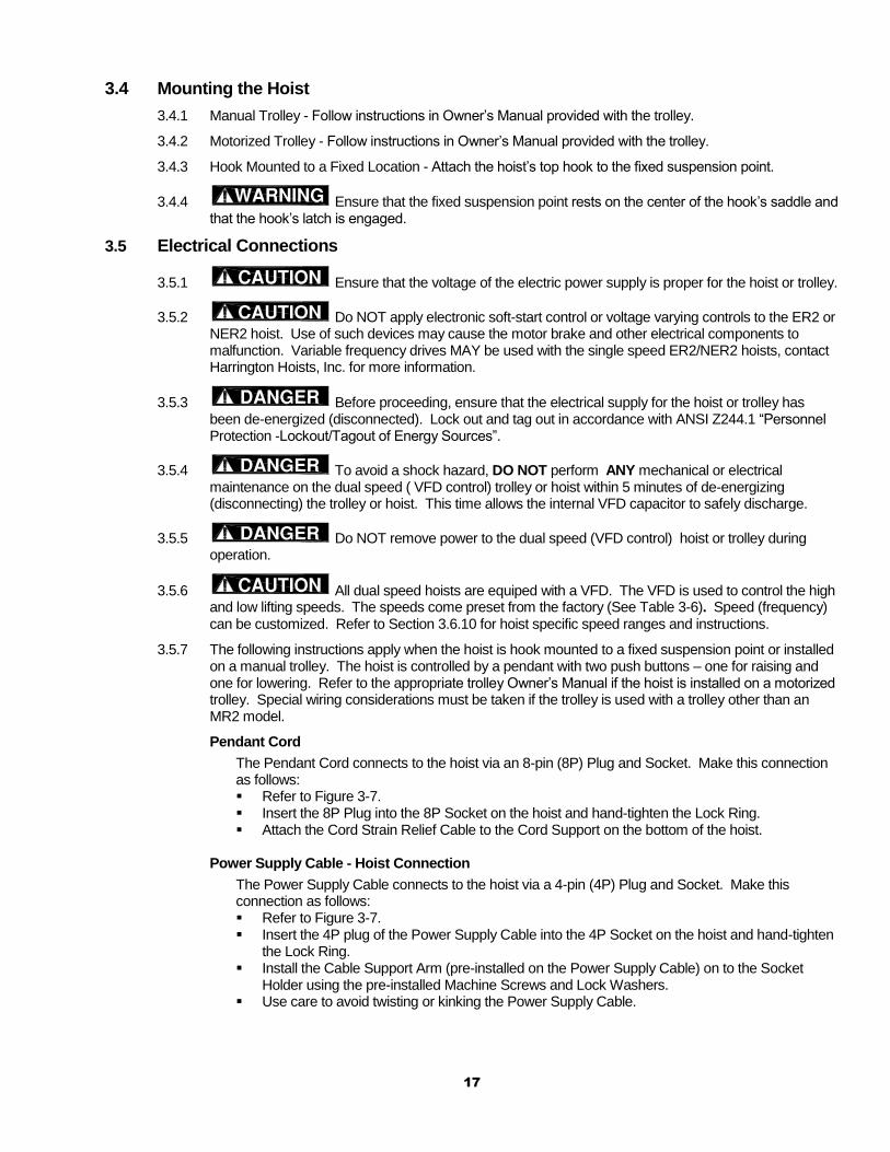
3.2.6 Verify that the load chain is not twisted or tangled prior to operating the hoist. Make sure the bottom hook on 2, 3 and 5 Ton double fall models is not capsized. See Figures 3-5 and 3-6. Correct all chain irregularities before conducting the first hoist operation.
Figure 3-5 Twist in Load Chain – 2, 3 and 5 Ton Double Fall Models
Figure 3-6 Capsized Hook and Chain –Double Fall Models
3.3 Mounting Location
3.3.1 Prior to mounting the hoist ensure that the suspension and the supporting structure are adequate to support the hoist and its loads. If necessary consult a professional that is qualified to evaluate the adequacy of the suspension location and its supporting structure.
3.3.2 See Section 6.8 for outdoor installation considerations.
17
3.4 Mounting the Hoist
3.4.1 Manual Trolley - Follow instructions in Owner’s Manual provided with the trolley.
3.4.2 Motorized Trolley - Follow instructions in Owner’s Manual provided with the trolley.
3.4.3 Hook Mounted to a Fixed Location - Attach the hoist’s top hook to the fixed suspension point.
3.4.4 Ensure that the fixed suspension point rests on the center of the hook’s saddle and that the hook’s latch is engaged.
3.5 Electrical Connections
3.5.1 Ensure that the voltage of the electric power supply is proper for the hoist or trolley.
3.5.2 Do NOT apply electronic soft-start control or voltage varying controls to the ER2 or NER2 hoist. Use of such devices may cause the motor brake and other electrical components to malfunction. Variable frequency drives MAY be used with the single speed ER2/NER2 hoists, contact Harrington Hoists, Inc. for more information.
3.5.3 Before proceeding, ensure that the electrical supply for the hoist or trolley has been de-energized (disconnected). Lock out and tag out in accordance with ANSI Z244.1 “Personnel Protection -Lockout/Tagout of Energy Sources”.
3.5.4 To avoid a shock hazard, DO NOT perform ANY mechanical or electrical maintenance on the dual speed ( VFD control) trolley or hoist within 5 minutes of de-energizing (disconnecting) the trolley or hoist. This time allows the internal VFD capacitor to safely discharge.
3.5.5 Do NOT remove power to the dual speed (VFD control) hoist or trolley during operation.
3.5.6 All dual speed hoists are equiped with a VFD. The VFD is used to control the high and low lifting speeds. The speeds come preset from the factory (See Table 3-6). Speed (frequency) can be customized. Refer to Section 3.6.10 for hoist specific speed ranges and instructions.
3.5.7 The following instructions apply when the hoist is hook mounted to a fixed suspension point or installed on a manual trolley. The hoist is controlled by a pendant with two push buttons – one for raising and one for lowering. Refer to the appropriate trolley Owner’s Manual if the hoist is installed on a motorized trolley. Special wiring considerations must be taken if the trolley is used with a trolley other than an MR2 model.
Pendant Cord
The Pendant Cord connects to the hoist via an 8-pin (8P) Plug and Socket. Make this connection as follows: Refer to Figure 3-7. Insert the 8P Plug into the 8P Socket on the hoist and hand-tighten the Lock Ring. Attach the Cord Strain Relief Cable to the Cord Support on the bottom of the hoist.
Power Supply Cable - Hoist Connection
The Power Supply Cable connects to the hoist via a 4-pin (4P) Plug and Socket. Make this connection as follows: Refer to Figure 3-7. Insert the 4P plug of the Power Supply Cable into the 4P Socket on the hoist and hand-tighten
the Lock Ring. Install the Cable Support Arm (pre-installed on the Power Supply Cable) on to the Socket
Holder using the pre-installed Machine Screws and Lock Washers. Use care to avoid twisting or kinking the Power Supply Cable.
18
Power Supply Cable - Installation
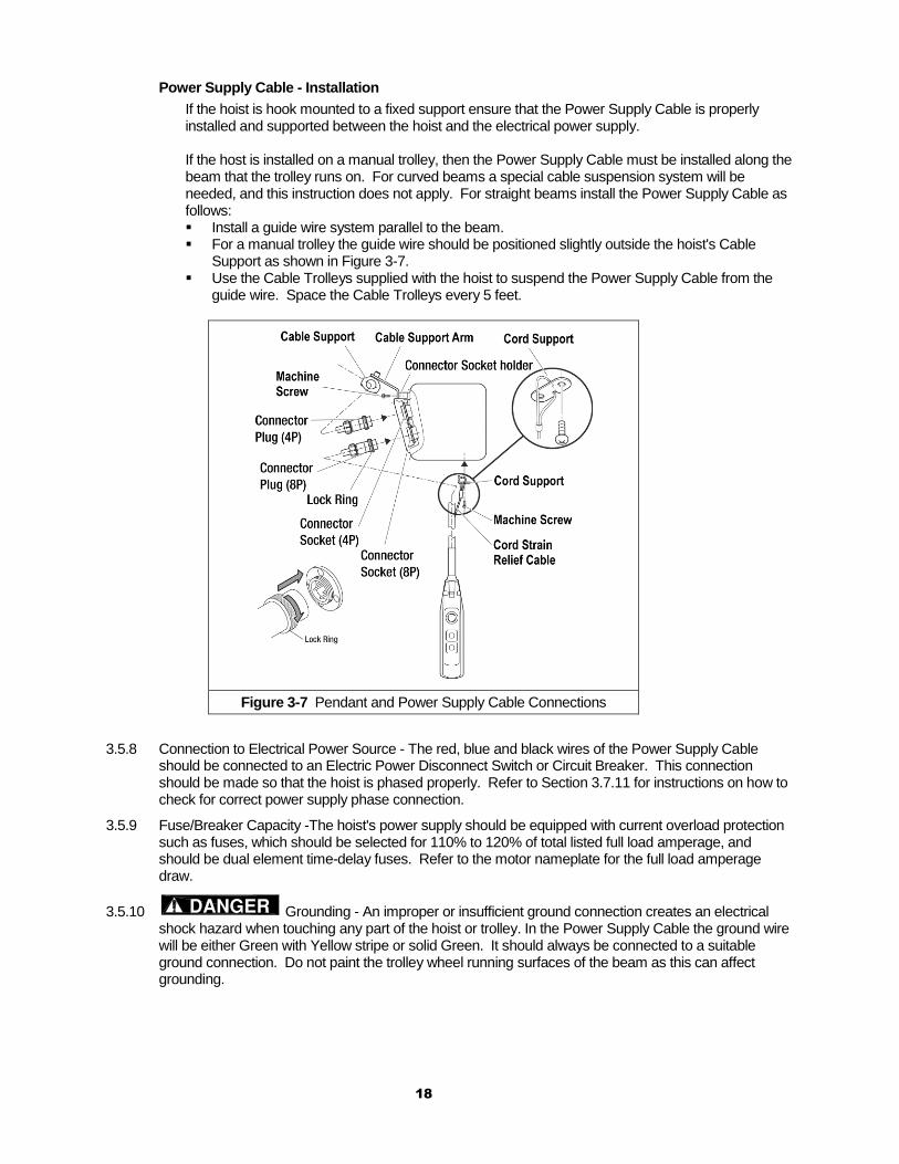
If the hoist is hook mounted to a fixed support ensure that the Power Supply Cable is properly installed and supported between the hoist and the electrical power supply. If the host is installed on a manual trolley, then the Power Supply Cable must be installed along the beam that the trolley runs on. For curved beams a special cable suspension system will be needed, and this instruction does not apply. For straight beams install the Power Supply Cable as follows: Install a guide wire system parallel to the beam. For a manual trolley the guide wire should be positioned slightly outside the hoist's Cable
Support as shown in Figure 3-7. Use the Cable Trolleys supplied with the hoist to suspend the Power Supply Cable from the
guide wire. Space the Cable Trolleys every 5 feet.
Figure 3-7 Pendant and Power Supply Cable Connections
3.5.8 Connection to Electrical Power Source - The red, blue and black wires of the Power Supply Cable should be connected to an Electric Power Disconnect Switch or Circuit Breaker. This connection should be made so that the hoist is phased properly. Refer to Section 3.7.11 for instructions on how to check for correct power supply phase connection.
3.5.9 Fuse/Breaker Capacity -The hoist's power supply should be equipped with current overload protection such as fuses, which should be selected for 110% to 120% of total listed full load amperage, and should be dual element time-delay fuses. Refer to the motor nameplate for the full load amperage draw.
3.5.10 Grounding - An improper or insufficient ground connection creates an electrical shock hazard when touching any part of the hoist or trolley. In the Power Supply Cable the ground wire will be either Green with Yellow stripe or solid Green. It should always be connected to a suitable ground connection. Do not paint the trolley wheel running surfaces of the beam as this can affect grounding.
19
3.6 VFD Setup (Dual Speed Only)
3.6.1 To avoid a shock hazard, DO NOT perform ANY mechanical or electrical maintenance on the dual speed ( VFD control) trolley or hoist within 5 minutes of de-energizing (disconnecting) the trolley or hoist. This time allows the internal VFD capacitor to safely discharge.
3.6.2 Do Not remove power to the dual speed (VFD control) hoist or trolley during operation.
3.6.3 All dual speed hoists are equiped with a VFD. The VFD is used to control the high and low lifting speeds. The speeds come preset from the factory (Table 3-6). Speed (frequency) can be customized. Refer to Section 3.6.10 for hoist specific speed ranges and instructions.
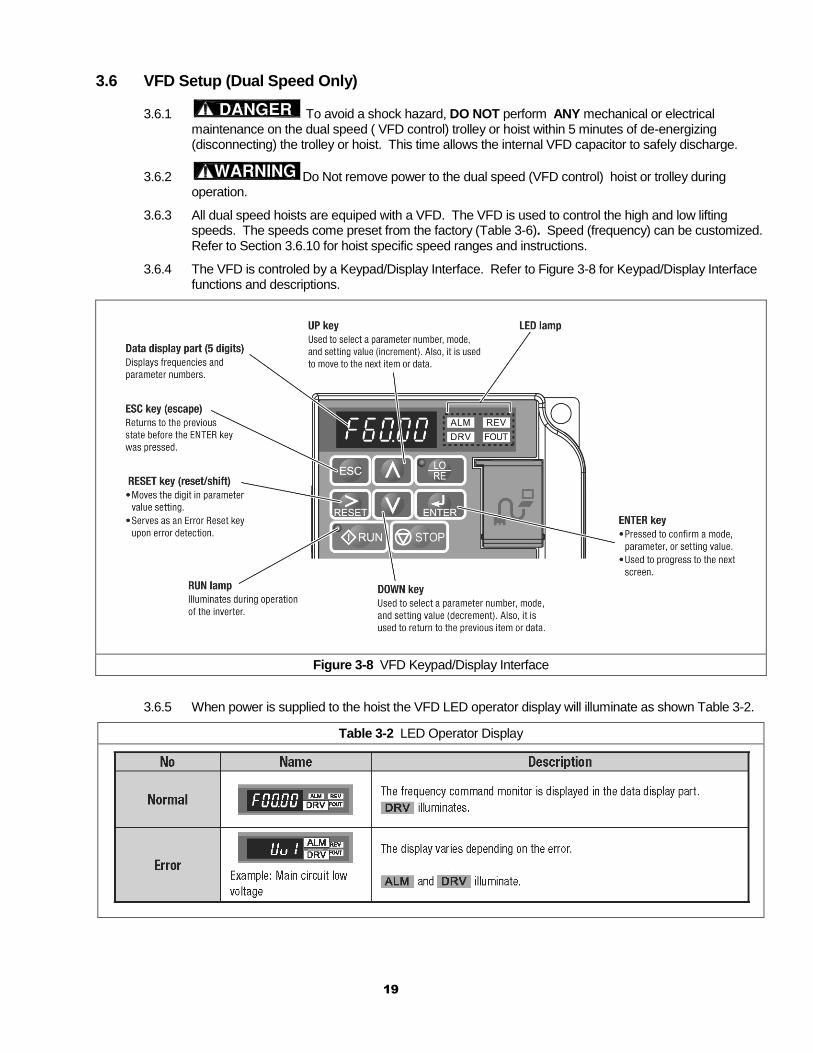
3.6.4 The VFD is controled by a Keypad/Display Interface. Refer to Figure 3-8 for Keypad/Display Interface functions and descriptions.
Figure 3-8 VFD Keypad/Display Interface
3.6.5 When power is supplied to the hoist the VFD LED operator display will illuminate as shown Table 3-2.
Table 3-2 LED Operator Display
20
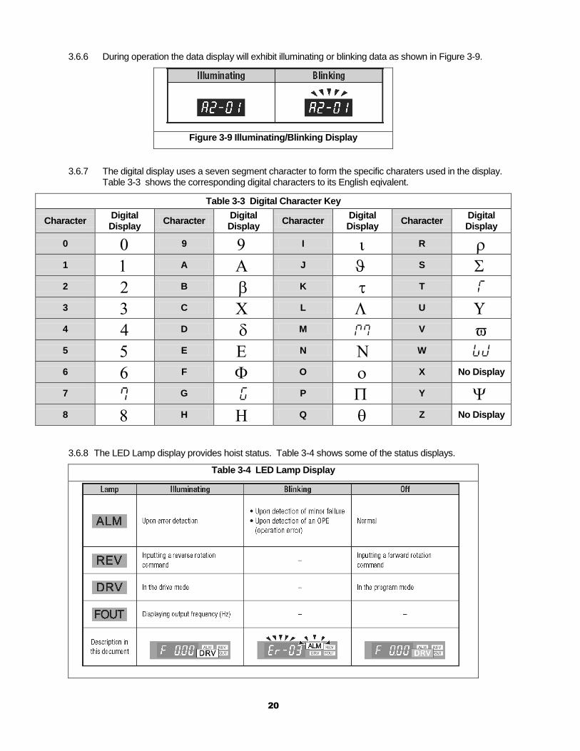
3.6.6 During operation the data display will exhibit illuminating or blinking data as shown in Figure 3-9.
Figure 3-9 Illuminating/Blinking Display
3.6.7 The digital display uses a seven segment character to form the specific charaters used in the display. Table 3-3 shows the corresponding digital characters to its English eqivalent.
Table 3-3 Digital Character Key
Character Digital Display
Character Digital Display
Character Digital Display
Character Digital Display
0 9 I R 1 A J S 2 B K T 3 C L U 4 D M V 5 E N W 6 F O X No Display
7 G P Y 8 H Q Z No Display
3.6.8 The LED Lamp display provides hoist status. Table 3-4 shows some of the status displays.
Table 3-4 LED Lamp Display
21
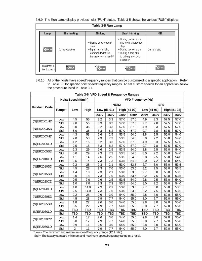
3.6.9 The Run Lamp display provides hoist “RUN” status. Table 3-5 shows the various “RUN” displays.
Table 3-5 Run Lamp
3.6.10 All of the hoists have speed/frequency ranges that can be customized to a specific application. Refer
to Table 3-6 for specific hoist speed/frequency ranges. To set custom speeds for an application, follow the procedure listed in Table 3-7.
Table 3-6 VFD Speed & Frequency Ranges
Product Code
Hoist Speed (ft/min) VFD Frequency (Hz)
Range* Low High
NER2 ER2
Low (d1-01) High (d1-02) Low (d1-01) High (d1-02)
230V 460V 230V 460V 230V 460V 230V 460V
(N)ER2001HD Low 4.5 55 3.2 3.3 57.0 57.0 4.9 3.3 57.5 57.0
Std 9.0 55 8.3 8.2 57.0 57.0 9.7 7.8 57.5 57.0
(N)ER2003SD Low 3.0 36 3.2 3.3 57.0 57.0 4.9 3.3 57.5 57.0
Std 6.0 36 8.3 8.2 57.0 57.0 9.7 7.8 57.5 57.0
(N)ER2003HD Low 4.3 53 2.6 2.5 53.5 54.0 2.8 2.5 55.0 54.0
Std 9.0 53 7.3 7.3 53.5 54.0 8.0 7.2 55.0 54.0
(N)ER2005LD Low 1.2 15 3.2 3.3 57.0 57.0 4.9 3.3 57.5 57.0
Std 2.5 15 8.3 8.2 57.0 57.0 9.7 7.8 57.5 57.0
(N)ER2005SD Low 2.3 29 2.6 2.5 53.5 54.0 2.8 2.5 55.0 54.0
Std 5.0 29 7.3 7.3 53.5 54.0 8.0 7.2 55.0 54.0
(N)ER2010LD Low 1.1 14 2.6 2.5 53.5 54.0 2.8 2.5 55.0 54.0
Std 2.5 14 7.3 7.3 53.5 54.0 8.0 7.2 55.0 54.0
(N)ER2010SD Low 2.2 28 2.3 2.1 53.0 53.5 2.7 3.0 53.0 53.5
Std 4.5 28 7.3 7.0 53.0 53.5 8.2 7.5 53.0 53.5
(N)ER2015SD Low 1.4 18 2.3 2.1 53.0 53.5 2.7 3.0 53.0 53.5
Std 3.0 18 7.3 7.0 53.0 53.5 8.2 7.5 53.0 53.5
(N)ER2020CD Low 0.5 7.0 2.6 2.5 53.5 54.0 2.8 2.5 55.0 54.0
Std 1.0 7.0 7.3 7.3 53.5 54.0 8.0 7.2 55.0 54.0
(N)ER2020LD Low 1.0 14.0 2.3 2.1 53.0 53.5 2.7 3.0 53.0 53.5
Std 2.5 14.0 7.3 7.0 53.0 53.5 8.2 7.5 53.0 53.5
(N)ER2020SD Low 2.2 28 2.6 3.0 54.0 55.0 2.8 3.0 52.0 55.0
Std 4.5 28 7.9 7.7 54.0 55.0 8.0 7.7 52.0 55.0
(N)ER2025SD Low 1.8 22 2.6 3.0 54.0 55.0 2.8 3.0 52.0 55.0
Std 3.5 22 7.9 7.7 54.0 55.0 8.0 7.7 52.0 55.0
(N)ER2030LD Low TBD TBD TBD TBD TBD TBD TBD TBD TBD TBD
Std TBD TBD TBD TBD TBD TBD TBD TBD TBD TBD
(N)ER2030CD Low 1.4 17 2.6 3.0 54.0 55.0 2.8 3.0 52.0 55.0
Std 3.0 17 7.9 7.7 54.0 55.0 8.0 7.7 52.0 55.0
(N)ER2050LD Low 0.9 11 2.6 3.0 54.0 55.0 2.8 3.0 52.0 55.0
Std 2 11 7.9 7.7 54.0 55.0 8.0 7.7 52.0 55.0 *Low = The minimum and maximum speed/frequency range (12:1 ratio). Std = The factory standard minimum and maximum speed/frequency range (6:1 ratio).
22
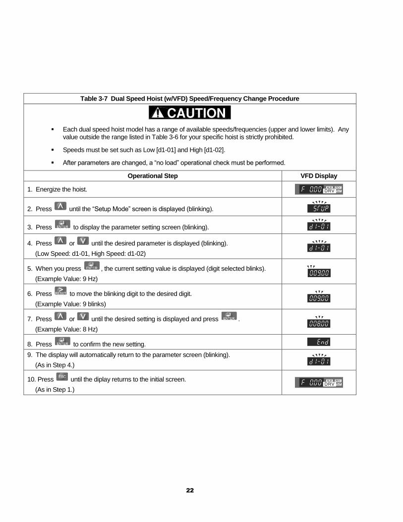
Table 3-7 Dual Speed Hoist (w/VFD) Speed/Frequency Change Procedure
Each dual speed hoist model has a range of available speeds/frequencies (upper and lower limits). Any value outside the range listed in Table 3-6 for your specific hoist is strictly prohibited.
Speeds must be set such as Low [d1-01] and High [d1-02].
After parameters are changed, a “no load” operational check must be performed.
Operational Step VFD Display
1. Energize the hoist.
2. Press until the “Setup Mode” screen is displayed (blinking).
3. Press to display the parameter setting screen (blinking).
4. Press or until the desired parameter is displayed (blinking).
(Low Speed: d1-01, High Speed: d1-02)
5. When you press , the current setting value is displayed (digit selected blinks).
(Example Value: 9 Hz)
6. Press to move the blinking digit to the desired digit.
(Example Value: 9 blinks)
7. Press or until the desired setting is displayed and press .
(Example Value: 8 Hz)
8. Press to confirm the new setting.
9. The display will automatically return to the parameter screen (blinking).
(As in Step 4.)
10. Press until the diplay returns to the initial screen.
(As in Step 1.)
23
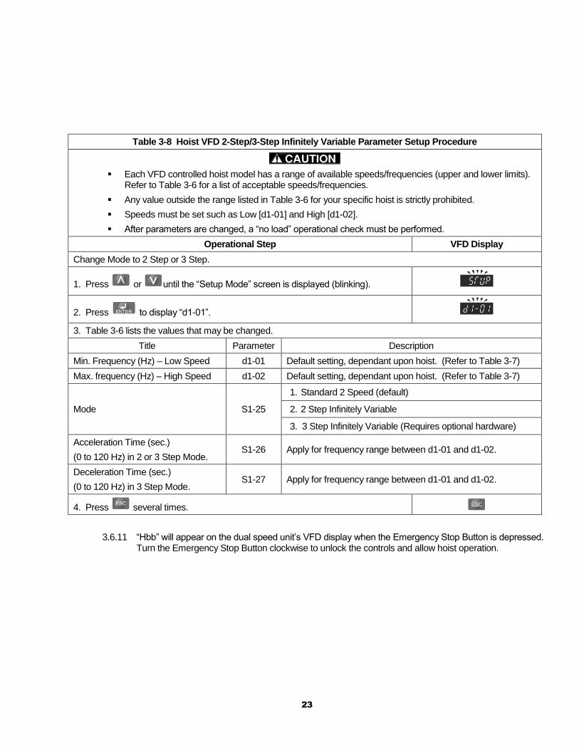
Table 3-8 Hoist VFD 2-Step/3-Step Infinitely Variable Parameter Setup Procedure
Each VFD controlled hoist model has a range of available speeds/frequencies (upper and lower limits). Refer to Table 3-6 for a list of acceptable speeds/frequencies.
Any value outside the range listed in Table 3-6 for your specific hoist is strictly prohibited.
Speeds must be set such as Low [d1-01] and High [d1-02].
After parameters are changed, a “no load” operational check must be performed.
Operational Step VFD Display
Change Mode to 2 Step or 3 Step.
1. Press or until the “Setup Mode” screen is displayed (blinking).
2. Press to display “d1-01”.
3. Table 3-6 lists the values that may be changed.
Title Parameter Description
Min. Frequency (Hz) – Low Speed d1-01 Default setting, dependant upon hoist. (Refer to Table 3-7)
Max. frequency (Hz) – High Speed d1-02 Default setting, dependant upon hoist. (Refer to Table 3-7)
Mode S1-25
1. Standard 2 Speed (default)
2. 2 Step Infinitely Variable
3. 3 Step Infinitely Variable (Requires optional hardware)
Acceleration Time (sec.)
(0 to 120 Hz) in 2 or 3 Step Mode. S1-26 Apply for frequency range between d1-01 and d1-02.
Deceleration Time (sec.)
(0 to 120 Hz) in 3 Step Mode. S1-27 Apply for frequency range between d1-01 and d1-02.
4. Press several times.
3.6.11 “Hbb” will appear on the dual speed unit’s VFD display when the Emergency Stop Button is depressed. Turn the Emergency Stop Button clockwise to unlock the controls and allow hoist operation.
24
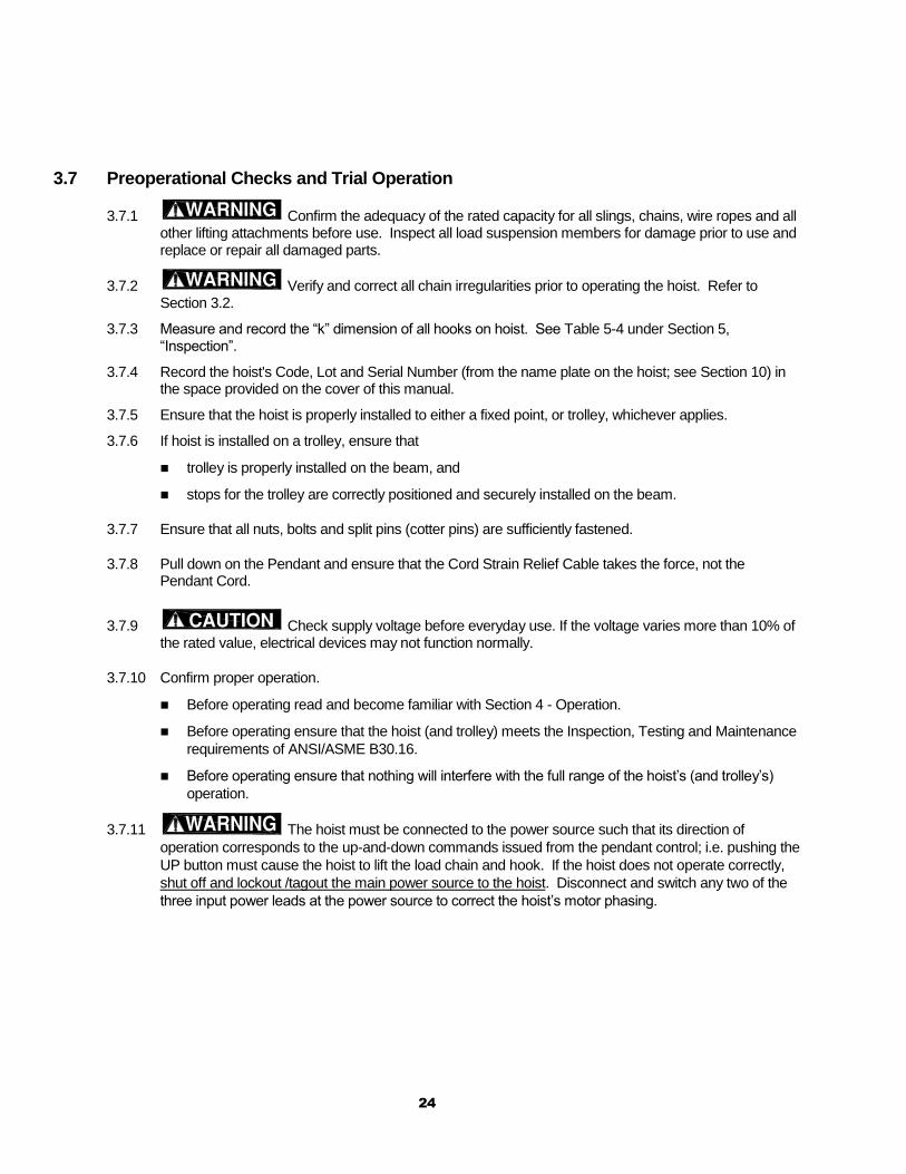
3.7 Preoperational Checks and Trial Operation
3.7.1 Confirm the adequacy of the rated capacity for all slings, chains, wire ropes and all other lifting attachments before use. Inspect all load suspension members for damage prior to use and replace or repair all damaged parts.
3.7.2 Verify and correct all chain irregularities prior to operating the hoist. Refer to Section 3.2.
3.7.3 Measure and record the “k” dimension of all hooks on hoist. See Table 5-4 under Section 5, “Inspection”.
3.7.4 Record the hoist's Code, Lot and Serial Number (from the name plate on the hoist; see Section 10) in the space provided on the cover of this manual.
3.7.5 Ensure that the hoist is properly installed to either a fixed point, or trolley, whichever applies.
3.7.6 If hoist is installed on a trolley, ensure that
trolley is properly installed on the beam, and
stops for the trolley are correctly positioned and securely installed on the beam.
3.7.7 Ensure that all nuts, bolts and split pins (cotter pins) are sufficiently fastened.
3.7.8 Pull down on the Pendant and ensure that the Cord Strain Relief Cable takes the force, not the Pendant Cord.
3.7.9 Check supply voltage before everyday use. If the voltage varies more than 10% of the rated value, electrical devices may not function normally.
3.7.10 Confirm proper operation.
Before operating read and become familiar with Section 4 - Operation.
Before operating ensure that the hoist (and trolley) meets the Inspection, Testing and Maintenance
requirements of ANSI/ASME B30.16.
Before operating ensure that nothing will interfere with the full range of the hoist’s (and trolley’s)
operation.
3.7.11 The hoist must be connected to the power source such that its direction of
operation corresponds to the up-and-down commands issued from the pendant control; i.e. pushing the
UP button must cause the hoist to lift the load chain and hook. If the hoist does not operate correctly,
shut off and lockout /tagout the main power source to the hoist. Disconnect and switch any two of the
three input power leads at the power source to correct the hoist’s motor phasing.
25
4.0 Operation
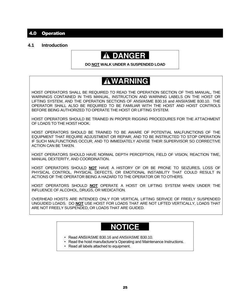
4.1 Introduction
DO NOT WALK UNDER A SUSPENDED LOAD
HOIST OPERATORS SHALL BE REQUIRED TO READ THE OPERATION SECTION OF THIS MANUAL, THE WARNINGS CONTAINED IN THIS MANUAL, INSTRUCTION AND WARNING LABELS ON THE HOIST OR LIFTING SYSTEM, AND THE OPERATION SECTIONS OF ANSI/ASME B30.16 and ANSI/ASME B30.10. THE OPERATOR SHALL ALSO BE REQUIRED TO BE FAMILIAR WITH THE HOIST AND HOIST CONTROLS BEFORE BEING AUTHORIZED TO OPERATE THE HOIST OR LIFTING SYSTEM. HOIST OPERATORS SHOULD BE TRAINED IN PROPER RIGGING PROCEDURES FOR THE ATTACHMENT OF LOADS TO THE HOIST HOOK. HOIST OPERATORS SHOULD BE TRAINED TO BE AWARE OF POTENTIAL MALFUNCTIONS OF THE EQUIPMENT THAT REQUIRE ADJUSTMENT OR REPAIR, AND TO BE INSTRUCTED TO STOP OPERATION IF SUCH MALFUNCTIONS OCCUR, AND TO IMMEDIATELY ADVISE THEIR SUPERVISOR SO CORRECTIVE ACTION CAN BE TAKEN. HOIST OPERATORS SHOULD HAVE NORMAL DEPTH PERCEPTION, FIELD OF VISION, REACTION TIME, MANUAL DEXTERITY, AND COORDINATION. HOIST OPERATORS SHOULD NOT HAVE A HISTORY OF OR BE PRONE TO SEIZURES, LOSS OF PHYSICAL CONTROL, PHYSICAL DEFECTS, OR EMOTIONAL INSTABILITY THAT COULD RESULT IN ACTIONS OF THE OPERATOR BEING A HAZARD TO THE OPERATOR OR TO OTHERS. HOIST OPERATORS SHOULD NOT OPERATE A HOIST OR LIFTING SYSTEM WHEN UNDER THE INFLUENCE OF ALCOHOL, DRUGS, OR MEDICATION. OVERHEAD HOISTS ARE INTENDED ONLY FOR VERTICAL LIFTING SERVICE OF FREELY SUSPENDED UNGUIDED LOADS. DO NOT USE HOIST FOR LOADS THAT ARE NOT LIFTED VERTICALLY, LOADS THAT ARE NOT FREELY SUSPENDED, OR LOADS THAT ARE GUIDED.
• Read ANSI/ASME B30.16 and ANSI/ASME B30.10. • Read the hoist manufacturer’s Operating and Maintenance Instructions. • Read all labels attached to equipment.
26
The operation of an overhead hoist involves more than activating the hoist’s controls. Per the ANSI/ASME B30 standards, the use of an overhead hoist is subject to certain hazards that cannot be mitigated by engineered features, but only by the exercise of intelligence, care, common sense, and experience in anticipating the effects and results of activating the hoist’s controls. Use this guidance in conjunction with other warnings, cautions, and notices in this manual to govern the operation and use of your overhead hoist.
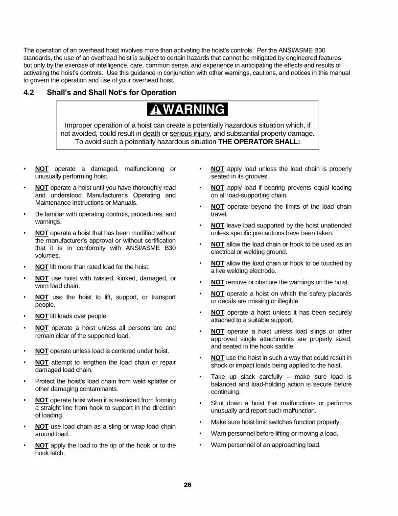
4.2 Shall’s and Shall Not’s for Operation
Improper operation of a hoist can create a potentially hazardous situation which, if not avoided, could result in death or serious injury, and substantial property damage.
To avoid such a potentially hazardous situation THE OPERATOR SHALL:
• NOT operate a damaged, malfunctioning or
unusually performing hoist.
• NOT operate a hoist until you have thoroughly read and understood Manufacturer’s Operating and Maintenance Instructions or Manuals.
• Be familiar with operating controls, procedures, and warnings.
• NOT operate a hoist that has been modified without the manufacturer’s approval or without certification that it is in conformity with ANSI/ASME B30 volumes.
• NOT lift more than rated load for the hoist.
• NOT use hoist with twisted, kinked, damaged, or worn load chain.
• NOT use the hoist to lift, support, or transport people.
• NOT lift loads over people.
• NOT operate a hoist unless all persons are and
remain clear of the supported load.
• NOT operate unless load is centered under hoist.
• NOT attempt to lengthen the load chain or repair damaged load chain.
• Protect the hoist’s load chain from weld splatter or other damaging contaminants.
• NOT operate hoist when it is restricted from forming a straight line from hook to support in the direction of loading.
• NOT use load chain as a sling or wrap load chain around load.
• NOT apply the load to the tip of the hook or to the hook latch.
• NOT apply load unless the load chain is properly seated in its grooves.
• NOT apply load if bearing prevents equal loading on all load-supporting chain.
• NOT operate beyond the limits of the load chain travel.
• NOT leave load supported by the hoist unattended unless specific precautions have been taken.
• NOT allow the load chain or hook to be used as an electrical or welding ground.
• NOT allow the load chain or hook to be touched by a live welding electrode.
• NOT remove or obscure the warnings on the hoist.
• NOT operate a hoist on which the safety placards or decals are missing or illegible
• NOT operate a hoist unless it has been securely attached to a suitable support.
• NOT operate a hoist unless load slings or other approved single attachments are properly sized, and seated in the hook saddle.
• NOT use the hoist in such a way that could result in shock or impact loads being applied to the hoist.
• Take up slack carefully – make sure load is balanced and load-holding action is secure before continuing.
• Shut down a hoist that malfunctions or performs unusually and report such malfunction.
• Make sure hoist limit switches function properly.
• Warn personnel before lifting or moving a load.
• Warn personnel of an approaching load.
27
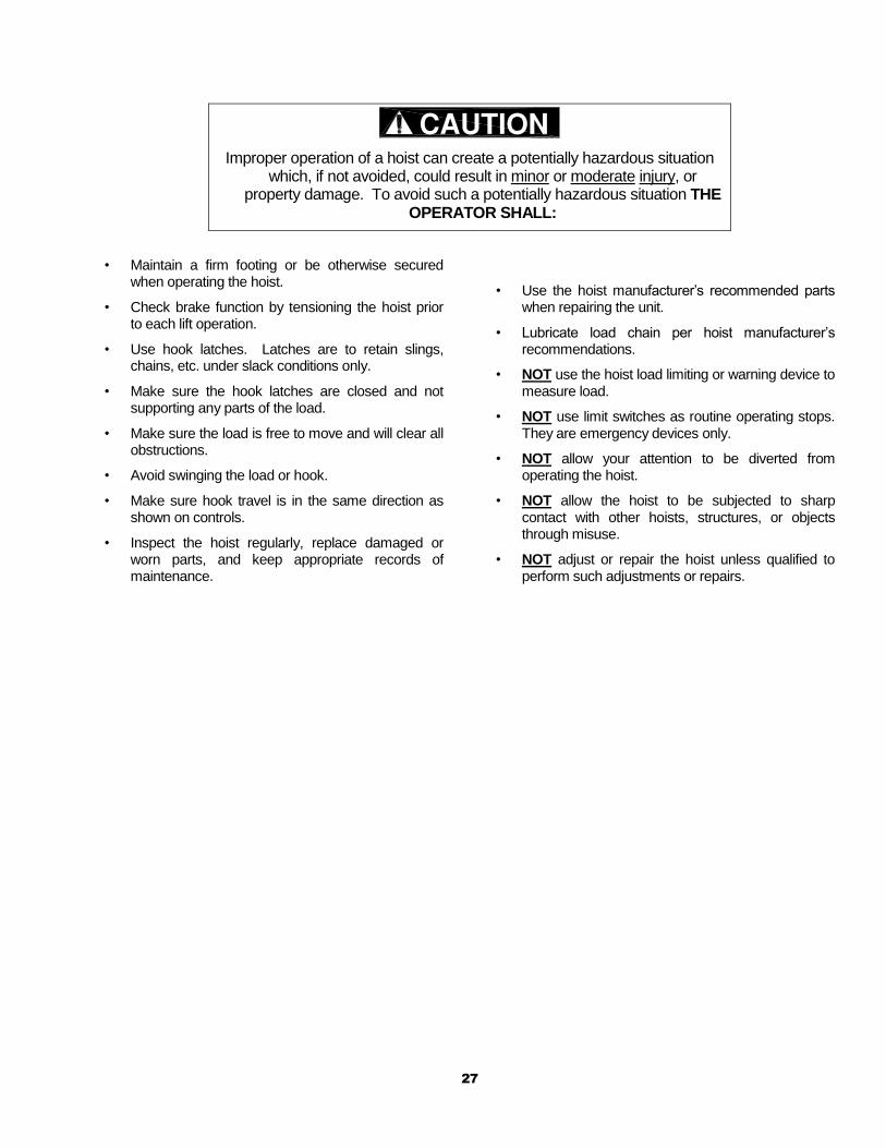
Improper operation of a hoist can create a potentially hazardous situation which, if not avoided, could result in minor or moderate injury, or
property damage. To avoid such a potentially hazardous situation THE OPERATOR SHALL:
• Maintain a firm footing or be otherwise secured when operating the hoist.
• Check brake function by tensioning the hoist prior to each lift operation.
• Use hook latches. Latches are to retain slings, chains, etc. under slack conditions only.
• Make sure the hook latches are closed and not supporting any parts of the load.
• Make sure the load is free to move and will clear all obstructions.
• Avoid swinging the load or hook.
• Make sure hook travel is in the same direction as shown on controls.
• Inspect the hoist regularly, replace damaged or worn parts, and keep appropriate records of maintenance.
• Use the hoist manufacturer’s recommended parts when repairing the unit.
• Lubricate load chain per hoist manufacturer’s recommendations.
• NOT use the hoist load limiting or warning device to measure load.
• NOT use limit switches as routine operating stops. They are emergency devices only.
• NOT allow your attention to be diverted from operating the hoist.
• NOT allow the hoist to be subjected to sharp contact with other hoists, structures, or objects through misuse.
• NOT adjust or repair the hoist unless qualified to perform such adjustments or repairs.
28
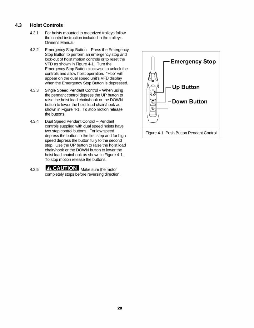
4.3 Hoist Controls
4.3.1 For hoists mounted to motorized trolleys follow the control instruction included in the trolley's Owner's Manual.
4.3.2 Emergency Stop Button – Press the Emergency Stop Button to perform an emergency stop and lock-out of hoist motion controls or to reset the VFD as shown in Figure 4-1. Turn the Emergency Stop Button clockwise to unlock the controls and allow hoist operation. “Hbb” will appear on the dual speed unit’s VFD display when the Emergency Stop Button is depressed.
4.3.3 Single Speed Pendant Control – When using the pendant control depress the UP button to raise the hoist load chain/hook or the DOWN button to lower the hoist load chain/hook as shown in Figure 4-1. To stop motion release the buttons.
4.3.4 Dual Speed Pendant Control – Pendant controls supplied with dual speed hoists have two step control buttons. For low speed depress the button to the first step and for high speed depress the button fully to the second step. Use the UP button to raise the hoist load chain/hook or the DOWN button to lower the hoist load chain/hook as shown in Figure 4-1. To stop motion release the buttons.
4.3.5 Make sure the motor completely stops before reversing direction.
Figure 4-1 Push Button Pendant Control
29
5.0 Inspection
5.1 General
5.1.1 The inspection procedure herein is based on ANSI/ASME B30.16. The following definitions are from ANSI/ASME B30.16 and pertain to the inspection procedure below.
Designated Person – a person selected or assigned as being competent to perform the specific duties
to which he/she is assigned.
Qualified Person – a person who, by possession of a recognized degree or certificate of professional
standing, or who, by extensive knowledge, training, and experience, has successfully demonstrated the
ability to solve or resolve problems relating to the subject matter and work.
Normal Service – that distributed service which involves operation with randomly distributed loads
within the rated load limit, or uniform loads less than 65% of rated load for not more than 25% of the
time.
Heavy Service – that service which involves operation within the rated load limit which exceeds normal
service.
Severe Service – that service which involves normal or heavy service with abnormal operating
conditions.
5.2 Inspection Classification
5.2.1 Initial Inspection – prior to initial use, all new, altered, or modified hoists shall be inspected by a designated person to ensure compliance with the applicable provisions of this manual.
5.2.2 Inspection Classification – the inspection procedure for hoists in regular service is divided into two general classifications based upon the intervals at which inspection should be performed. The intervals in turn are dependent upon the nature of the critical components of the hoist and the degree of their exposure to wear, deterioration, or malfunction. The two general classifications are herein designated as FREQUENT and PERIODIC, with respective intervals between inspections as defined below.
5.2.3 FREQUENT Inspection – visual examinations by the operator or other designated personnel with intervals per the following criteria:
Normal service – monthly
Heavy service – weekly to monthly
Severe service – daily to weekly
Special or infrequent service – as recommended by a qualified person before and after each
occurrence.
5.2.4 PERIODIC Inspection – visual inspection by a designated person with intervals per the following criteria:
Normal service – yearly
Heavy service – semiannually
Severe service – quarterly
Special or infrequent service – as recommended by a qualified person before the first such
occurrence and as directed by the qualified person for any subsequent occurrences.
30
5.3 Frequent Inspection
5.3.1 Inspections should be made on a FREQUENT basis in accordance with Table 5-1, “Frequent Inspection.” Included in these FREQUENT Inspections are observations made during operation for any defects or damage that might appear between Periodic Inspections. Evaluation and resolution of the results of FREQUENT Inspections shall be made by a designated person such that the hoist is maintained in safe working condition.
Table 5-1 Frequent Inspection
All functional operating mechanisms for maladjustment and unusual sounds.
Operation of limit switch and associated components
Hoist braking system for proper operation
Hooks in accordance with ANSI/ASME B30.10
Hook latch operation
Load chain in accordance with Section 5.7
Load chain reeving for compliance with Section 3.2 and 6.5
5.4 Periodic Inspection
5.4.1 Inspections should be made on a PERIODIC basis in accordance with Table 5-2, “Periodic Inspection.” Evaluation and resolution of the results of PERIODIC Inspections shall be made by a designated person such that the hoist is maintained in safe working condition.
5.4.2 For inspections where load suspension parts of the hoist are disassembled, a load test per ANSI/ASME B30.16 must be performed on the hoist after it is re-assembled and prior to its return to service.
Table 5-2 Periodic Inspection
Requirements of frequent inspection.
Evidence of loose bolts, nuts, or rivets.
Evidence of worn, corroded, cracked, or distorted parts such as load blocks, suspension housing, chain attachments, clevises, yokes, suspension bolts, shafts, gears, bearings, pins and rollers.
Evidence of damage to hook retaining nuts or collars and pins, and welds or rivets used to secure the retaining members.
Evidence of damage or excessive wear of load and idler sheaves.
Evidence of excessive wear on motor or load brake.
Electrical apparatus for signs of pitting or any deterioration of visible controller contacts.
Evidence of damage of supporting structure or trolley, if used.
Function labels on pendant control stations for legibility.
Warning label properly attached to the hoist and legible (see Section 1.2).
End connections of load chain.
31
5.5 Occasionally Used Hoists
5.5.1 Hoists that are used infrequently shall be inspected as follows prior to placing in service:
Hoist Idle More Than 1 Month, Less Than 1 Year: Inspect per FREQUENT Inspection criteria in
Section 5.3.
Hoist Idle More Than 1 Year: Inspect per PERIODIC Inspection criteria in Section 5.4.
5.6 Inspection Records
5.6.1 Dated inspection reports and records should be maintained at time intervals corresponding to those that apply for the hoist’s PERIODIC interval per Section 5.2.4. These records should be stored where they are available to personnel involved with the inspection, maintenance, or operation of the hoist.
5.6.2 A long range chain inspection program should be established and should include records of examination of chains removed from service so a relationship can be established between visual observation and actual condition of the chain.
5.7 Inspection Methods and Criteria
5.7.1 This section covers the inspection of specific items. The list of items in this section is based on those listed in ANSI/ASME B30.16 for the Frequent and Periodic Inspection. In accordance with ANSI/ASME B30.16, these inspections are not intended to involve disassembly of the hoist. Rather, disassembly for further inspection would be required if frequent or periodic inspection results so indicate. Such disassembly and further inspection should only be performed by a qualified person trained in the disassembly and re-assembly of the hoist.
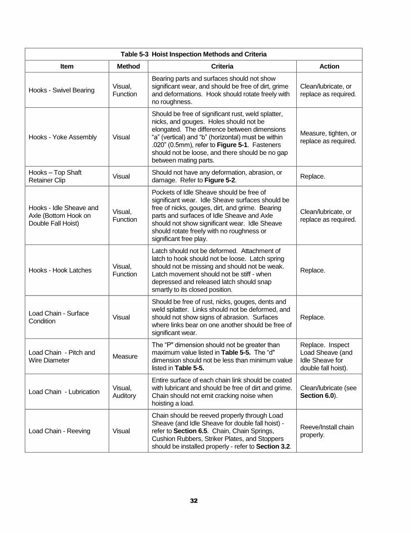
Table 5-3 Hoist Inspection Methods and Criteria
Item Method Criteria Action
Functional operating mechanisms.
Visual, Auditory
Mechanisms should be properly adjusted and should not produce unusual sounds when operated.
Repair or replace as required.
Limit Switches (upper and lower)
Function Proper operation. Actuation of limit switch should stop hoist.
Repair or replace as required.
Limit Lever Assembly Visual, Function
Lever should not be bent or significantly worn and should be able to move freely.
Replace.
Braking System Operation Function Braking distance with rated capacity should not exceed 3% of the lifting speed (approximately two chain links).
Repair or replace as required.
Hooks - Surface Condition Visual Should be free of significant rust, weld splatter, deep nicks, or gouges.
Replace.
Hooks - Fretting wear Measure The "u" and "t" dimensions should not be less than discard value listed in Table 5-4.
Replace.
Hooks - Stretch Measure
The "k" dimension should not be greater than 1.05 times that measured and recorded at the time of purchase (See Section 3.7). If recorded "k" values are not available for hooks when new, use nominal "k" values from Table 5-4.
Replace.
Hooks - Bent Shank or Neck
Visual Shank and neck portions of hook should be free of deformations.
Replace.
32
Table 5-3 Hoist Inspection Methods and Criteria
Item Method Criteria Action
Hooks - Swivel Bearing Visual, Function
Bearing parts and surfaces should not show significant wear, and should be free of dirt, grime and deformations. Hook should rotate freely with no roughness.
Clean/lubricate, or replace as required.
Hooks - Yoke Assembly Visual
Should be free of significant rust, weld splatter, nicks, and gouges. Holes should not be elongated. The difference between dimensions “a” (vertical) and “b” (horizontal) must be within .020” (0.5mm), refer to Figure 5-1. Fasteners should not be loose, and there should be no gap between mating parts.
Measure, tighten, or replace as required.
Hooks – Top Shaft Retainer Clip
Visual Should not have any deformation, abrasion, or damage. Refer to Figure 5-2.
Replace.
Hooks - Idle Sheave and Axle (Bottom Hook on Double Fall Hoist)
Visual, Function
Pockets of Idle Sheave should be free of significant wear. Idle Sheave surfaces should be free of nicks, gouges, dirt, and grime. Bearing parts and surfaces of Idle Sheave and Axle should not show significant wear. Idle Sheave should rotate freely with no roughness or significant free play.
Clean/lubricate, or replace as required.
Hooks - Hook Latches Visual, Function
Latch should not be deformed. Attachment of latch to hook should not be loose. Latch spring should not be missing and should not be weak. Latch movement should not be stiff - when depressed and released latch should snap smartly to its closed position.
Replace.
Load Chain - Surface Condition
Visual
Should be free of rust, nicks, gouges, dents and weld splatter. Links should not be deformed, and should not show signs of abrasion. Surfaces where links bear on one another should be free of significant wear.
Replace.
Load Chain - Pitch and Wire Diameter
Measure
The “P" dimension should not be greater than maximum value listed in Table 5-5. The “d" dimension should not be less than minimum value listed in Table 5-5.
Replace. Inspect Load Sheave (and Idle Sheave for double fall hoist).
Load Chain - Lubrication Visual, Auditory
Entire surface of each chain link should be coated with lubricant and should be free of dirt and grime. Chain should not emit cracking noise when hoisting a load.
Clean/lubricate (see Section 6.0).
Load Chain - Reeving Visual
Chain should be reeved properly through Load Sheave (and Idle Sheave for double fall hoist) - refer to Section 6.5. Chain, Chain Springs, Cushion Rubbers, Striker Plates, and Stoppers should be installed properly - refer to Section 3.2.
Reeve/Install chain properly.
33
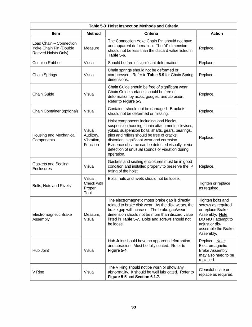
Table 5-3 Hoist Inspection Methods and Criteria
Item Method Criteria Action
Load Chain – Connection Yoke Chain Pin (Double Reeved Hoists Only)
Measure
The Connection Yoke Chain Pin should not have and apparent deformation. The “d” dimension should not be less than the discard value listed in Table 5-6.
Replace.
Cushion Rubber Visual Should be free of significant deformation. Replace.
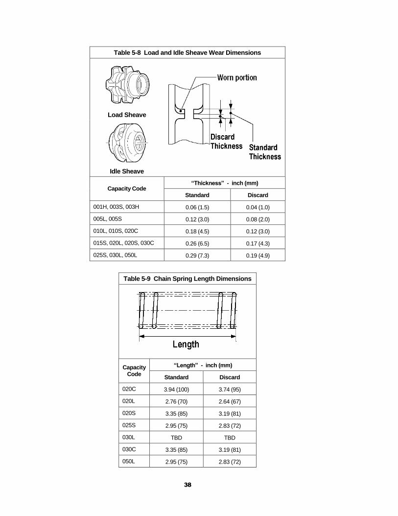
Chain Springs Visual Chain springs should not be deformed or compressed. Refer to Table 5-9 for Chain Spring dimensions.
Replace.
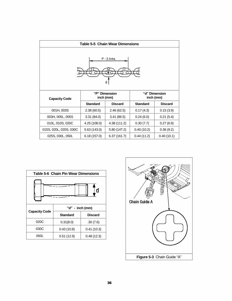
Chain Guide Visual
Chain Guide should be free of significant wear. Chain Guide surfaces should be free of deformation by nicks, gouges, and abrasion. Refer to Figure 5-3.
Replace.
Chain Container (optional) Visual Container should not be damaged. Brackets should not be deformed or missing.
Replace.
Housing and Mechanical Components
Visual, Auditory, Vibration, Function
Hoist components including load blocks, suspension housing, chain attachments, clevises, yokes, suspension bolts, shafts, gears, bearings, pins and rollers should be free of cracks, distortion, significant wear and corrosion. Evidence of same can be detected visually or via detection of unusual sounds or vibration during operation.
Replace.
Gaskets and Sealing Enclosures
Visual Gaskets and sealing enclosures must be in good condition and installed properly to preserve the IP rating of the hoist.
Replace.
Bolts, Nuts and Rivets
Visual, Check with Proper Tool
Bolts, nuts and rivets should not be loose. Tighten or replace as required.
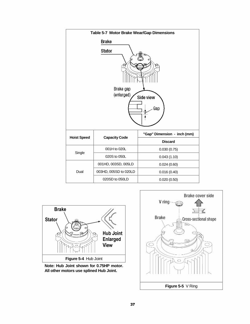
Electromagnetic Brake Assembly
Measure, Visual
The electromagnetic motor brake gap is directly related to brake disk wear. As the disk wears, the brake gap will increase. The brake gap/wear dimension should not be more than discard value listed in Table 5-7. Bolts and screws should not be loose.
Tighten bolts and screws as required or replace Brake Assembly. Note: DO NOT attempt to adjust or dis- assemble the Brake Assembly.
Hub Joint Visual
Hub Joint should have no apparent deformation and abrasion. Must be fully seated. Refer to Figure 5-4.
Replace. Note: Electromagnetic Brake Assembly may also need to be replaced.
V Ring Visual The V Ring should not be worn or show any abnormality. It should be well lubricated. Refer to Figure 5-5 and Section 6.1.7.
Clean/lubricate or replace as required.
34
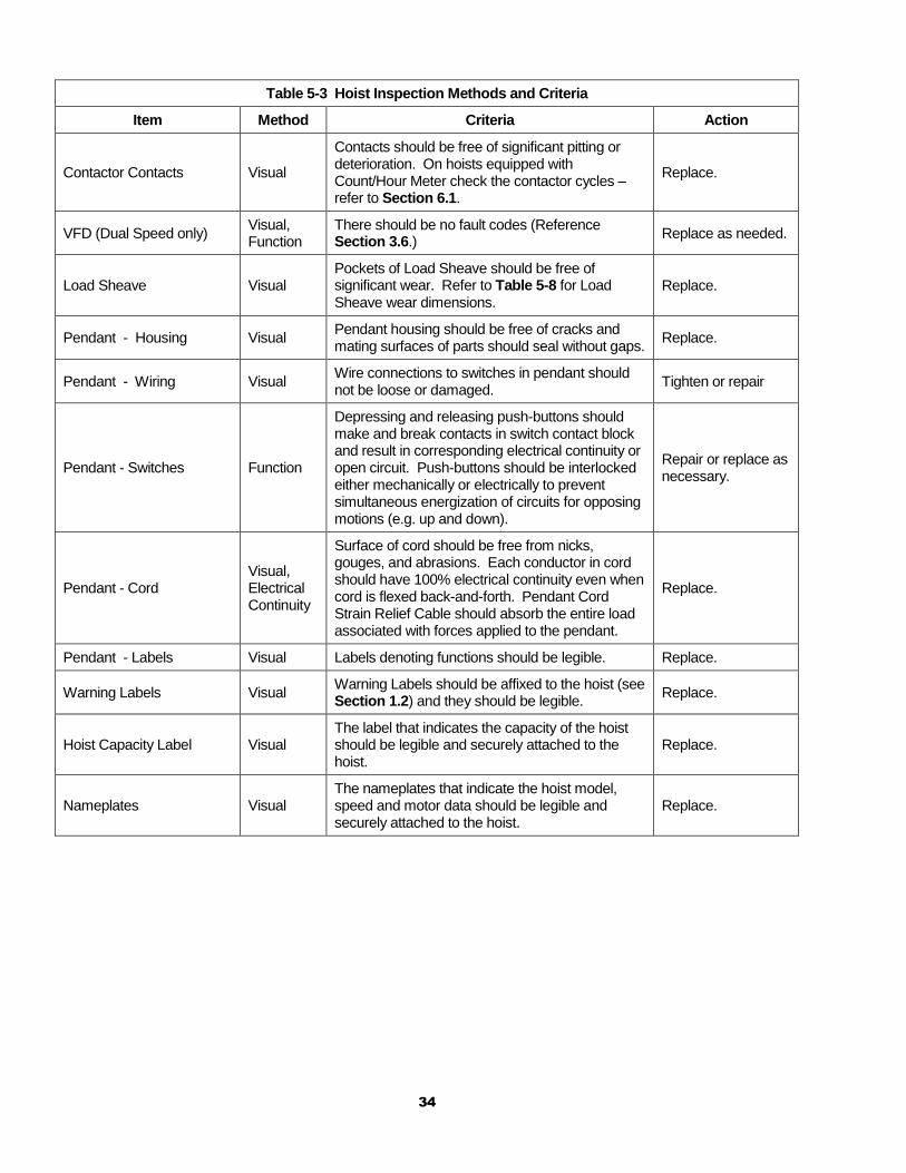
Table 5-3 Hoist Inspection Methods and Criteria
Item Method Criteria Action
Contactor Contacts Visual
Contacts should be free of significant pitting or deterioration. On hoists equipped with Count/Hour Meter check the contactor cycles – refer to Section 6.1.
Replace.
VFD (Dual Speed only) Visual, Function
There should be no fault codes (Reference Section 3.6.)
Replace as needed.
Load Sheave Visual Pockets of Load Sheave should be free of significant wear. Refer to Table 5-8 for Load Sheave wear dimensions.
Replace.
Pendant - Housing Visual Pendant housing should be free of cracks and mating surfaces of parts should seal without gaps.
Replace.
Pendant - Wiring Visual Wire connections to switches in pendant should not be loose or damaged.
Tighten or repair
Pendant - Switches Function
Depressing and releasing push-buttons should make and break contacts in switch contact block and result in corresponding electrical continuity or open circuit. Push-buttons should be interlocked either mechanically or electrically to prevent simultaneous energization of circuits for opposing motions (e.g. up and down).
Repair or replace as necessary.
Pendant - Cord Visual, Electrical Continuity
Surface of cord should be free from nicks, gouges, and abrasions. Each conductor in cord should have 100% electrical continuity even when cord is flexed back-and-forth. Pendant Cord Strain Relief Cable should absorb the entire load associated with forces applied to the pendant.
Replace.
Pendant - Labels Visual Labels denoting functions should be legible. Replace.
Warning Labels Visual Warning Labels should be affixed to the hoist (see Section 1.2) and they should be legible.
Replace.
Hoist Capacity Label Visual The label that indicates the capacity of the hoist should be legible and securely attached to the hoist.
Replace.
Nameplates Visual The nameplates that indicate the hoist model, speed and motor data should be legible and securely attached to the hoist.
Replace.
35
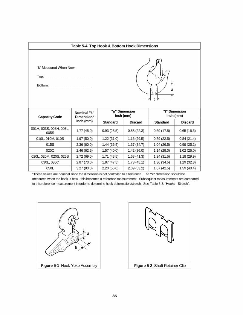
Table 5-4 Top Hook & Bottom Hook Dimensions
“k” Measured When New:
Top: _________________________
Bottom: ______________________
Capacity Code Nominal "k" Dimension* inch (mm)
"u" Dimension inch (mm)
"t" Dimension inch (mm)
Standard Discard Standard Discard
001H, 003S, 003H, 005L, 005S
1.77 (45.0) 0.93 (23.5) 0.88 (22.3) 0.69 (17.5) 0.65 (16.6)
010L, 010M, 010S 1.97 (50.0) 1.22 (31.0) 1.16 (29.5) 0.89 (22.5) 0.84 (21.4)
015S 2.36 (60.0) 1.44 (36.5) 1.37 (34.7) 1.04 (26.5) 0.99 (25.2)
020C 2.46 (62.5) 1.57 (40.0) 1.42 (36.0) 1.14 (29.0) 1.02 (26.0)
020L, 020M, 020S, 025S 2.72 (69.0) 1.71 (43.5) 1.63 (41.3) 1.24 (31.5) 1.18 (29.9)
030L, 030C 2.87 (73.0) 1.87 (47.5) 1.78 (45.1) 1.36 (34.5) 1.29 (32.8)
050L 3.27 (83.0) 2.20 (56.0) 2.09 (53.2) 1.67 (42.5) 1.59 (40.4)
*These values are nominal since the dimension is not controlled to a tolerance. The "k" dimension should be
measured when the hook is new - this becomes a reference measurement. Subsequent measurements are compared
to this reference measurement in order to determine hook deformation/stretch. See Table 5-3, “Hooks - Stretch”.
Figure 5-1 Hook Yoke Assembly Figure 5-2 Shaft Retainer Clip
36
Table 5-5 Chain Wear Dimensions
Capacity Code
“P” Dimension inch (mm)
“d” Dimension inch (mm)
Standard Discard Standard Discard
001H, 003S 2.38 (60.5) 2.46 (62.5) 0.17 (4.3) 0.15 (3.9)
003H, 005L, 005S 3.31 (84.0) 3.41 (86.5) 0.24 (6.0) 0.21 (5.4)
010L, 010S, 020C 4.25 (108.0) 4.38 (111.2) 0.30 (7.7) 0.27 (6.9)
015S, 020L, 020S, 030C 5.63 (143.0) 5.80 (147.2) 0.40 (10.2) 0.36 (9.2)
025S, 030L, 050L 6.18 (157.0) 6.37 (161.7) 0.44 (11.2) 0.40 (10.1)
Table 5-6 Chain Pin Wear Dimensions
Capacity Code “d” - inch (mm)
Standard Discard
020C 0.31(8.0) .30 (7.6)
030C 0.43 (10.8) 0.41 (10.3)
050L 0.51 (12.9) 0.48 (12.3)
Figure 5-3 Chain Guide “A”
37
Table 5-7 Motor Brake Wear/Gap Dimensions
Hoist Speed Capacity Code "Gap" Dimension - inch (mm)
Discard
Single 001H to 020L 0.030 (0.75)
020S to 050L 0.043 (1.10)
Dual
001HD, 003SD, 005LD 0.024 (0.60)
003HD, 005SD to 020LD 0.016 (0.40)
020SD to 050LD 0.020 (0.50)
Figure 5-4 Hub Joint
Note: Hub Joint shown for 0.75HP motor.
All other motors use splined Hub Joint.
Figure 5-5 V Ring
38
Table 5-8 Load and Idle Sheave Wear Dimensions
Load Sheave
Idle Sheave
Capacity Code “Thickness” - inch (mm)
Standard Discard
001H, 003S, 003H 0.06 (1.5) 0.04 (1.0)
005L, 005S 0.12 (3.0) 0.08 (2.0)
010L, 010S, 020C 0.18 (4.5) 0.12 (3.0)
015S, 020L, 020S, 030C 0.26 (6.5) 0.17 (4.3)
025S, 030L, 050L 0.29 (7.3) 0.19 (4.9)
Table 5-9 Chain Spring Length Dimensions
Capacity Code
“Length” - inch (mm)
Standard Discard
020C 3.94 (100) 3.74 (95)
020L 2.76 (70) 2.64 (67)
020S 3.35 (85) 3.19 (81)
025S 2.95 (75) 2.83 (72)
030L TBD TBD
030C 3.35 (85) 3.19 (81)
050L 2.95 (75) 2.83 (72)
39
6.0 Maintenance and Handling
6.1 Count/Hour Meter
A count/hour function is included in all NER2/ER2 hoists. A Count/Hour Meter is included in the single speed hoists and a count/hour function is one of the VFD parameters in the dual speed hoists.
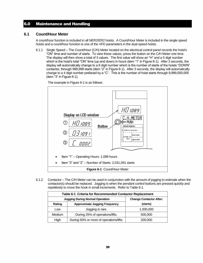
6.1.1 Single Speed – The Count/Hour (C/H) Meter located on the electrical control panel records the hoist's “ON” time and number of starts. To view these values, press the button on the C/H Meter one time. The display will then show a total of 3 values. The first value will show an "H" and a 5 digit number which is the hoist's total “ON” time (up and down) in hours (item “1” in Figure 6-1). After 3 seconds, the display will automatically change to a 6 digit number which is the number of starts of the hoists “DOWN” contactor, through 999,999 starts (item “2” in Figure 6-1). After 3 seconds, the display will automatically change to a 4 digit number prefaced by a “C”. This is the number of hoist starts through 9,999,000,000 (item “3” in Figure 6-1).
The example in Figure 6-1 is as follows:
Item “1” – Operating Hours: 1,089 hours
Item “3” and “2” – Number of Starts: 2,031,091 starts
Figure 6-1 Count/Hour Meter
6.1.2 Contactor – The C/H Meter can be used in conjunction with the amount of jogging to estimate when the contactor(s) should be replaced. Jogging is when the pendant control buttons are pressed quickly and repetitively to move the hook in small increments. Refer to Table 6-1.
Table 6-1 Criteria for Recommended Contactor Replacement
Jogging During Normal Operation Change Contactor After:
(starts) Rating Approximate Jogging Frequency
Low Jogging is rare. 1,000,000
Medium During 25% of operations/lifts. 500,000
High During 50% or more of operations/lifts. 200,000
40
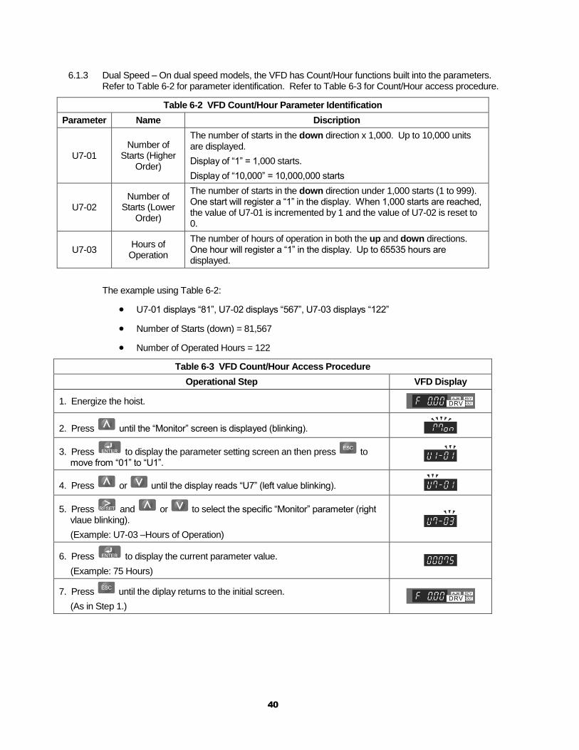
6.1.3 Dual Speed – On dual speed models, the VFD has Count/Hour functions built into the parameters. Refer to Table 6-2 for parameter identification. Refer to Table 6-3 for Count/Hour access procedure.
Table 6-2 VFD Count/Hour Parameter Identification
Parameter Name Discription
U7-01 Number of
Starts (Higher Order)
The number of starts in the down direction x 1,000. Up to 10,000 units are displayed.
Display of “1” = 1,000 starts.
Display of “10,000” = 10,000,000 starts
U7-02 Number of
Starts (Lower Order)
The number of starts in the down direction under 1,000 starts (1 to 999). One start will register a “1” in the display. When 1,000 starts are reached, the value of U7-01 is incremented by 1 and the value of U7-02 is reset to 0.
U7-03 Hours of
Operation
The number of hours of operation in both the up and down directions. One hour will register a “1” in the display. Up to 65535 hours are displayed.
The example using Table 6-2:
U7-01 displays “81”, U7-02 displays “567”, U7-03 displays “122”
Number of Starts (down) = 81,567
Number of Operated Hours = 122
Table 6-3 VFD Count/Hour Access Procedure
Operational Step VFD Display
1. Energize the hoist.
2. Press until the “Monitor” screen is displayed (blinking).
3. Press to display the parameter setting screen an then press to move from “01” to “U1”.
4. Press or until the display reads “U7” (left value blinking).
5. Press and or to select the specific “Monitor” parameter (right vlaue blinking).
(Example: U7-03 –Hours of Operation)
6. Press to display the current parameter value.
(Example: 75 Hours)
7. Press until the diplay returns to the initial screen.
(As in Step 1.)
41
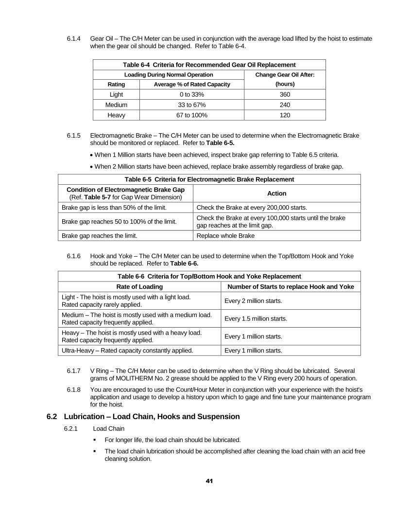
6.1.4 Gear Oil – The C/H Meter can be used in conjunction with the average load lifted by the hoist to estimate when the gear oil should be changed. Refer to Table 6-4.
Table 6-4 Criteria for Recommended Gear Oil Replacement
Loading During Normal Operation Change Gear Oil After:
(hours) Rating Average % of Rated Capacity
Light 0 to 33% 360
Medium 33 to 67% 240
Heavy 67 to 100% 120
6.1.5 Electromagnetic Brake – The C/H Meter can be used to determine when the Electromagnetic Brake should be monitored or replaced. Refer to Table 6-5.
When 1 Million starts have been achieved, inspect brake gap referring to Table 6.5 criteria.
When 2 Million starts have been achieved, replace brake assembly regardless of brake gap.
Table 6-5 Criteria for Electromagnetic Brake Replacement
Condition of Electromagnetic Brake Gap (Ref. Table 5-7 for Gap Wear Dimension)
Action
Brake gap is less than 50% of the limit. Check the Brake at every 200,000 starts.
Brake gap reaches 50 to 100% of the limit. Check the Brake at every 100,000 starts until the brake gap reaches at the limit gap.
Brake gap reaches the limit. Replace whole Brake
6.1.6 Hook and Yoke – The C/H Meter can be used to determine when the Top/Bottom Hook and Yoke should be replaced. Refer to Table 6-6.
Table 6-6 Criteria for Top/Bottom Hook and Yoke Replacement
Rate of Loading Number of Starts to replace Hook and Yoke
Light - The hoist is mostly used with a light load. Rated capacity rarely applied.
Every 2 million starts.
Medium – The hoist is mostly used with a medium load. Rated capacity frequently applied.
Every 1.5 million starts.
Heavy – The hoist is mostly used with a heavy load. Rated capacity frequently applied.
Every 1 million starts.
Ultra-Heavy – Rated capacity constantly applied. Every 1 million starts.
6.1.7 V Ring – The C/H Meter can be used to determine when the V Ring should be lubricated. Several grams of MOLITHERM No. 2 grease should be applied to the V Ring every 200 hours of operation.
6.1.8 You are encouraged to use the Count/Hour Meter in conjunction with your experience with the hoist's application and usage to develop a history upon which to gage and fine tune your maintenance program for the hoist.
6.2 Lubrication – Load Chain, Hooks and Suspension
6.2.1 Load Chain
For longer life, the load chain should be lubricated.
The load chain lubrication should be accomplished after cleaning the load chain with an acid free cleaning solution.
42
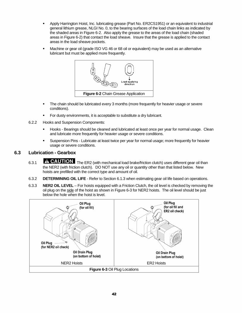
Apply Harrington Hoist, Inc. lubricating grease (Part No. ER2CS1951) or an equivalent to industrial general lithium grease, NLGI No. 0, to the bearing surfaces of the load chain links as indicated by the shaded areas in Figure 6-2. Also apply the grease to the areas of the load chain (shaded areas in Figure 6-2) that contact the load sheave. Insure that the grease is applied to the contact areas in the load sheave pockets.
Machine or gear oil (grade ISO VG 46 or 68 oil or equivalent) may be used as an alternative lubricant but must be applied more frequently.
Figure 6-2 Chain Grease Application
The chain should be lubricated every 3 months (more frequently for heavier usage or severe conditions).
For dusty environments, it is acceptable to substitute a dry lubricant.
6.2.2 Hooks and Suspension Components:
Hooks - Bearings should be cleaned and lubricated at least once per year for normal usage. Clean and lubricate more frequently for heavier usage or severe conditions.
Suspension Pins - Lubricate at least twice per year for normal usage; more frequently for heavier usage or severe conditions.
6.3 Lubrication - Gearbox
6.3.1 The ER2 (with mechanical load brake/friction clutch) uses different gear oil than the NER2 (with friction clutch). DO NOT use any oil or quantity other than that listed below. New hoists are prefilled with the correct type and amount of oil.
6.3.2 DETERMINING OIL LIFE - Refer to Section 6.1.3 when estimating gear oil life based on operations.
6.3.3 NER2 OIL LEVEL – For hoists equipped with a Friction Clutch, the oil level is checked by removing the oil plug on the side of the hoist as shown in Figure 6-3 for NER2 hoists. The oil level should be just below the hole when the hoist is level.
NER2 Hoists
ER2 Hoists
Figure 6-3 Oil Plug Locations
43
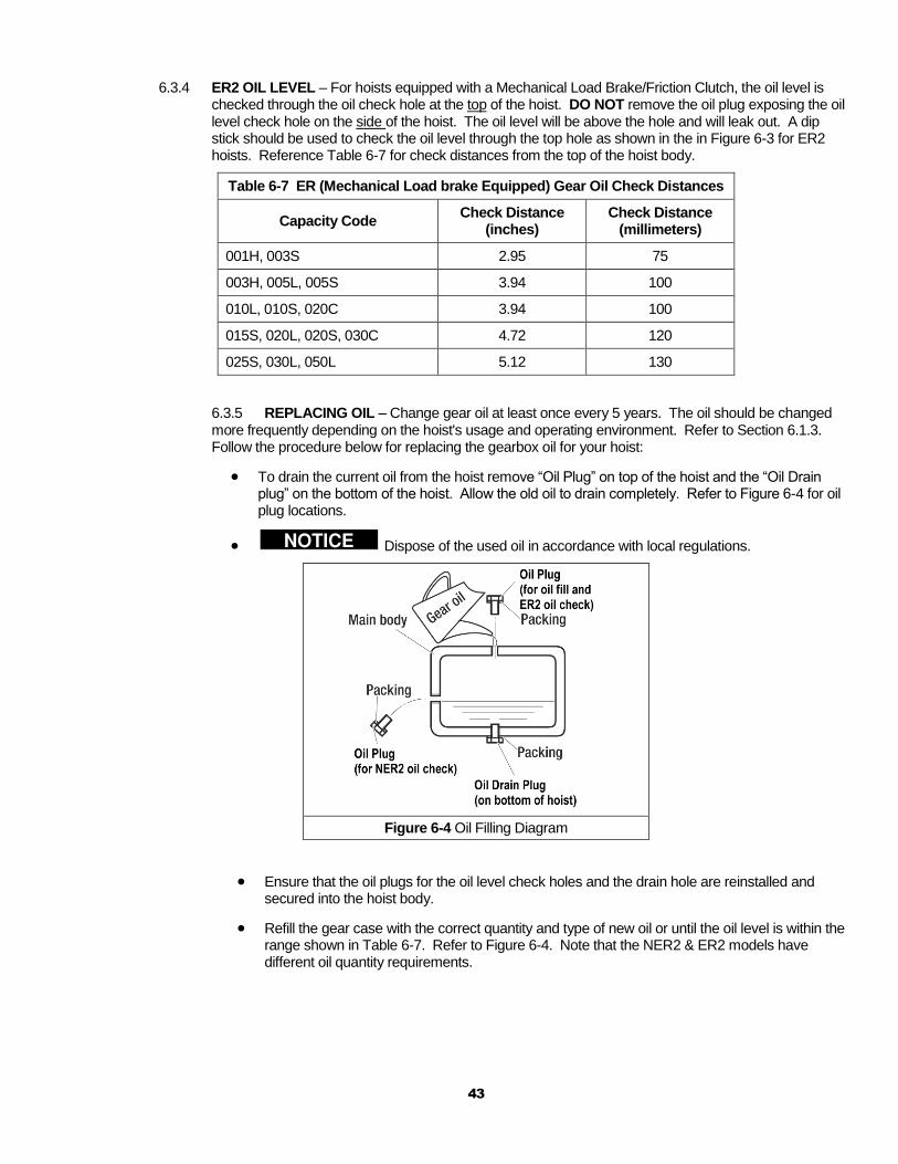
6.3.4 ER2 OIL LEVEL – For hoists equipped with a Mechanical Load Brake/Friction Clutch, the oil level is checked through the oil check hole at the top of the hoist. DO NOT remove the oil plug exposing the oil level check hole on the side of the hoist. The oil level will be above the hole and will leak out. A dip stick should be used to check the oil level through the top hole as shown in the in Figure 6-3 for ER2 hoists. Reference Table 6-7 for check distances from the top of the hoist body.
Table 6-7 ER (Mechanical Load brake Equipped) Gear Oil Check Distances
Capacity Code Check Distance
(inches) Check Distance
(millimeters)
001H, 003S 2.95 75
003H, 005L, 005S 3.94 100
010L, 010S, 020C 3.94 100
015S, 020L, 020S, 030C 4.72 120
025S, 030L, 050L 5.12 130
6.3.5 REPLACING OIL – Change gear oil at least once every 5 years. The oil should be changed more frequently depending on the hoist's usage and operating environment. Refer to Section 6.1.3. Follow the procedure below for replacing the gearbox oil for your hoist:
To drain the current oil from the hoist remove “Oil Plug” on top of the hoist and the “Oil Drain plug” on the bottom of the hoist. Allow the old oil to drain completely. Refer to Figure 6-4 for oil plug locations.
Dispose of the used oil in accordance with local regulations.
Figure 6-4 Oil Filling Diagram
Ensure that the oil plugs for the oil level check holes and the drain hole are reinstalled and secured into the hoist body.
Refill the gear case with the correct quantity and type of new oil or until the oil level is within the range shown in Table 6-7. Refer to Figure 6-4. Note that the NER2 & ER2 models have different oil quantity requirements.
44
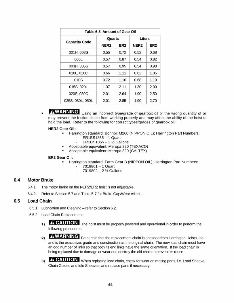
Table 6-8 Amount of Gear Oil
Capacity Code Quarts Liters
NER2 ER2 NER2 ER2
001H, 003S 0.55 0.72 0.52 0.68
005L 0.57 0.87 0.54 0.82
003H, 005S 0.57 0.95 0.54 0.90
010L, 020C 0.66 1.11 0.62 1.05
010S 0.72 1.16 0.68 1.10
015S, 020L 1.37 2.11 1.30 2.00
020S, 030C 2.01 2.64 1.90 2.50
025S, 030L, 050L 2.01 2.85 1.90 2.70
Using an incorrect type/grade of gearbox oil or the wrong quantity of oil may prevent the friction clutch from working properly and may affect the ability of the hoist to hold the load. Refer to the following for correct types/grades of gearbox oil:
NER2 Gear Oil: Harrington standard: Bonnoc M260 (NIPPON OIL); Harrington Part Numbers:
- ER1BS1855 – 1 Quart - ER1CS1855 – 2 ½ Gallons
Acceptable equivalent: Meropa 320 (TEXACO) Acceptable equivalent: Meropa 320 (CALTEX)
ER2 Gear Oil: Harrington standard: Farm Gear B (NIPPON OIL); Harrington Part Numbers:
- 7019801 – 1 Quart - 7019802 – 2 ½ Gallons
6.4 Motor Brake
6.4.1 The motor brake on the NER2/ER2 hoist is not adjustable.
6.4.2 Refer to Section 5.7 and Table 5-7 for Brake Gap/Wear criteria.
6.5 Load Chain
6.5.1 Lubrication and Cleaning – refer to Section 6.2.
6.5.2 Load Chain Replacement:
1) The hoist must be properly powered and operational in order to perform the
following procedures.
2) Be certain that the replacement chain is obtained from Harrington Hoists, Inc.
and is the exact size, grade and construction as the original chain. The new load chain must have
an odd number of links so that both its end links have the same orientation. If the load chain is
being replaced due to damage or wear out, destroy the old chain to prevent its reuse.
3) When replacing load chain, check for wear on mating parts, i.e. Load Sheave,
Chain Guides and Idle Sheaves, and replace parts if necessary.
45
4) Remove all chain components including the Bottom Hook Set Assembly, Stoppers, Cushion Rubbers,
Chain Springs, Striker Plates, Chain Pin and End Wire (or End Suspender) from the chain for reuse on new
chain. Inspect and replace any damaged or worn parts.
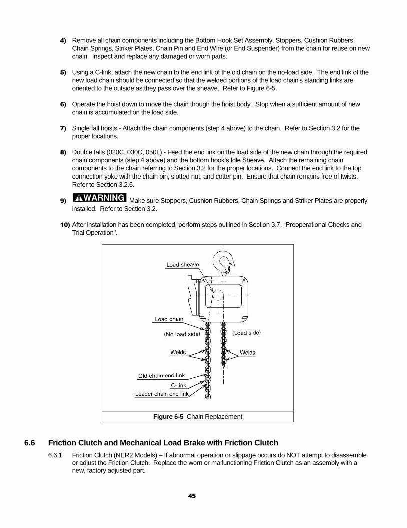
5) Using a C-link, attach the new chain to the end link of the old chain on the no-load side. The end link of the
new load chain should be connected so that the welded portions of the load chain's standing links are
oriented to the outside as they pass over the sheave. Refer to Figure 6-5.
6) Operate the hoist down to move the chain though the hoist body. Stop when a sufficient amount of new
chain is accumulated on the load side.
7) Single fall hoists - Attach the chain components (step 4 above) to the chain. Refer to Section 3.2 for the
proper locations.
8) Double falls (020C, 030C, 050L) - Feed the end link on the load side of the new chain through the required
chain components (step 4 above) and the bottom hook’s Idle Sheave. Attach the remaining chain
components to the chain referring to Section 3.2 for the proper locations. Connect the end link to the top
connection yoke with the chain pin, slotted nut, and cotter pin. Ensure that chain remains free of twists.
Refer to Section 3.2.6.
9) Make sure Stoppers, Cushion Rubbers, Chain Springs and Striker Plates are properly
installed. Refer to Section 3.2.
10) After installation has been completed, perform steps outlined in Section 3.7, “Preoperational Checks and
Trial Operation".
Figure 6-5 Chain Replacement
6.6 Friction Clutch and Mechanical Load Brake with Friction Clutch
6.6.1 Friction Clutch (NER2 Models) – If abnormal operation or slippage occurs do NOT attempt to disassemble or adjust the Friction Clutch. Replace the worn or malfunctioning Friction Clutch as an assembly with a new, factory adjusted part.
46
6.6.2 Mechanical Load Brake with Friction Clutch (ER2 Models) – If abnormal operation or slippage occurs do NOT attempt to disassemble or adjust the Mechanical Load Brake with Friction Clutch. Replace the worn or malfunctioning Mechanical Load Brake with Friction Clutch as an assembly with a new, factory adjusted part.
6.7 Storage
6.7.1 ER2 models with vented oil cap assemblies should be stored with the cap oriented up to prevent oil leakage.
6.7.2 The storage location should be clean and dry.
6.8 Outdoor Installation
6.8.1 The hoist/trolley should be covered when not in use.
6.8.2 The hoist/trolley MUST BE inspected and maintained according to the ‘Severe Service’ Inspection Classification. Refer to Section 5.0.
6.8.3 When reinstalling the control cover, the gasket MUST BE in good condition and installed properly to preserve the IP55 rating of the hoist.
6.8.4 When using a steel chain container, remove the plug to allow for the drainage of pooling water. When using a plastic chain container, drill a 1/8” hole in the plastic to allow for drainage. Canvas chain containers are not recommended for outdoor use.
6.8.5 Possibility of corrosion on components of the hoist/trolley increases for installations where salt air and high humidity are present. For installations where temperature variations introduce condensation/corrosion into the hoist, more frequent lubrication may be required.
6.8.6 NEMA 4 Pendants are recommended for outdoor use.
6.8.7 Refer to Section 2.1.3 for allowable environmental conditions.
6.9 Operational Environment
6.9.1 Non-conforming environment
A non-conforming environment is defined as one with any or all of the following.
Explosive gases or vapor.
Organic solvents or volatile powder
Excessive amounts of powder and dust of general substances
Excessive amount of acids or salts.
47
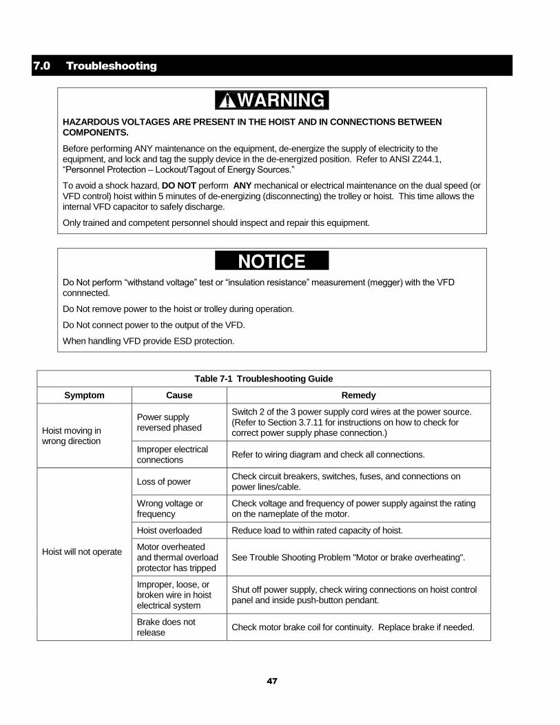
7.0 Troubleshooting
HAZARDOUS VOLTAGES ARE PRESENT IN THE HOIST AND IN CONNECTIONS BETWEEN COMPONENTS.
Before performing ANY maintenance on the equipment, de-energize the supply of electricity to the equipment, and lock and tag the supply device in the de-energized position. Refer to ANSI Z244.1, “Personnel Protection – Lockout/Tagout of Energy Sources.”
To avoid a shock hazard, DO NOT perform ANY mechanical or electrical maintenance on the dual speed (or VFD control) hoist within 5 minutes of de-energizing (disconnecting) the trolley or hoist. This time allows the internal VFD capacitor to safely discharge.
Only trained and competent personnel should inspect and repair this equipment.
Do Not perform “withstand voltage” test or “insulation resistance” measurement (megger) with the VFD connnected.
Do Not remove power to the hoist or trolley during operation.
Do Not connect power to the output of the VFD.
When handling VFD provide ESD protection.
Table 7-1 Troubleshooting Guide
Symptom Cause Remedy
Hoist moving in wrong direction
Power supply reversed phased
Switch 2 of the 3 power supply cord wires at the power source. (Refer to Section 3.7.11 for instructions on how to check for correct power supply phase connection.)
Improper electrical connections
Refer to wiring diagram and check all connections.
Hoist will not operate
Loss of power Check circuit breakers, switches, fuses, and connections on power lines/cable.
Wrong voltage or frequency
Check voltage and frequency of power supply against the rating on the nameplate of the motor.
Hoist overloaded Reduce load to within rated capacity of hoist.
Motor overheated and thermal overload protector has tripped
See Trouble Shooting Problem "Motor or brake overheating".
Improper, loose, or broken wire in hoist electrical system
Shut off power supply, check wiring connections on hoist control panel and inside push-button pendant.
Brake does not release
Check motor brake coil for continuity. Replace brake if needed.
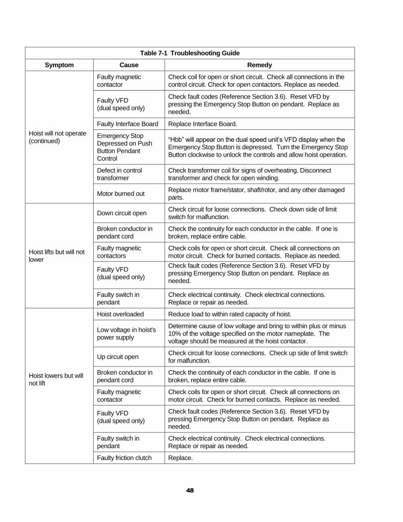
48
Table 7-1 Troubleshooting Guide
Symptom Cause Remedy
Hoist will not operate (continued)
Faulty magnetic contactor
Check coil for open or short circuit. Check all connections in the control circuit. Check for open contactors. Replace as needed.
Faulty VFD (dual speed only)
Check fault codes (Reference Section 3.6). Reset VFD by pressing the Emergency Stop Button on pendant. Replace as needed.
Faulty Interface Board Replace Interface Board.
Emergency Stop Depressed on Push Button Pendant Control
“Hbb” will appear on the dual speed unit’s VFD display when the Emergency Stop Button is depressed. Turn the Emergency Stop Button clockwise to unlock the controls and allow hoist operation.
Defect in control transformer
Check transformer coil for signs of overheating. Disconnect transformer and check for open winding.
Motor burned out Replace motor frame/stator, shaft/rotor, and any other damaged parts.
Hoist lifts but will not lower
Down circuit open Check circuit for loose connections. Check down side of limit switch for malfunction.
Broken conductor in pendant cord
Check the continuity for each conductor in the cable. If one is broken, replace entire cable.
Faulty magnetic contactors
Check coils for open or short circuit. Check all connections on motor circuit. Check for burned contacts. Replace as needed.
Faulty VFD (dual speed only)
Check fault codes (Reference Section 3.6). Reset VFD by pressing Emergency Stop Button on pendant. Replace as needed.
Faulty switch in pendant
Check electrical continuity. Check electrical connections. Replace or repair as needed.
Hoist lowers but will not lift
Hoist overloaded Reduce load to within rated capacity of hoist.
Low voltage in hoist's power supply
Determine cause of low voltage and bring to within plus or minus 10% of the voltage specified on the motor nameplate. The voltage should be measured at the hoist contactor.
Up circuit open Check circuit for loose connections. Check up side of limit switch for malfunction.
Broken conductor in pendant cord
Check the continuity of each conductor in the cable. If one is broken, replace entire cable.
Faulty magnetic contactor
Check coils for open or short circuit. Check all connections on motor circuit. Check for burned contacts. Replace as needed.
Faulty VFD (dual speed only)
Check fault codes (Reference Section 3.6). Reset VFD by pressing Emergency Stop Button on pendant. Replace as needed.
Faulty switch in pendant
Check electrical continuity. Check electrical connections. Replace or repair as needed.
Faulty friction clutch Replace.
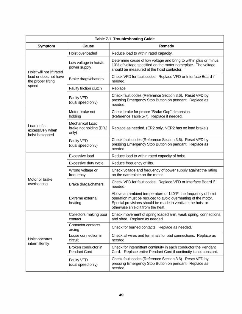
49
Table 7-1 Troubleshooting Guide
Symptom Cause Remedy
Hoist will not lift rated load or does not have the proper lifting speed
Hoist overloaded Reduce load to within rated capacity.
Low voltage in hoist's power supply
Determine cause of low voltage and bring to within plus or minus 10% of voltage specified on the motor nameplate. The voltage should be measured at the hoist contactor.
Brake drags/chatters Check VFD for fault codes. Replace VFD or Interface Board if needed.
Faulty friction clutch Replace.
Faulty VFD (dual speed only)
Check fault codes (Reference Section 3.6). Reset VFD by pressing Emergency Stop Button on pendant. Replace as needed.
Load drifts excessively when hoist is stopped
Motor brake not holding
Check brake for proper “Brake Gap” dimension. (Reference Table 5-7). Replace if needed.
Mechanical Load brake not holding (ER2 only)
Replace as needed. (ER2 only, NER2 has no load brake.)
Faulty VFD (dual speed only)
Check fault codes (Reference Section 3.6). Reset VFD by pressing Emergency Stop Button on pendant. Replace as needed.
Motor or brake overheating
Excessive load Reduce load to within rated capacity of hoist.
Excessive duty cycle Reduce frequency of lifts.
Wrong voltage or frequency
Check voltage and frequency of power supply against the rating on the nameplate on the motor.
Brake drags/chatters Check VFD for fault codes. Replace VFD or Interface Board if needed.
Extreme external heating
Above an ambient temperature of 140°F, the frequency of hoist operation must be reduced to avoid overheating of the motor. Special provisions should be made to ventilate the hoist or otherwise shield it from the heat.
Hoist operates intermittently
Collectors making poor contact
Check movement of spring loaded arm, weak spring, connections, and shoe. Replace as needed.
Contactor contacts arcing
Check for burned contacts. Replace as needed.
Loose connection in circuit
Check all wires and terminals for bad connections. Replace as needed.
Broken conductor in Pendant Cord
Check for intermittent continuity in each conductor the Pendant Cord. Replace entire Pendant Cord if continuity is not constant.
Faulty VFD (dual speed only)
Check fault codes (Reference Section 3.6). Reset VFD by pressing Emergency Stop Button on pendant. Replace as needed.
50
8.0 Warranty
All products sold by Harrington Hoists, Inc. are warranted to be free from defects in material and workmanship from date of shipment by Harrington for the following periods:
1 year – Electric and Air Powered Hoists (excluding (N)ER2 Enhanced Features
Models), Powered Trolleys, Powered Tiger Track Jibs and Gantries,
Crane Components, Below the Hook Devices, Spare / Replacement Parts
2 years – Manual Hoists & Trolleys, Beam Clamps
3 years – (N)ER2 Enhanced Features Model Hoists
5 years – Manual Tiger Track Jibs and Gantries, TNER Pull - Rotor Motor Brake
10 years – (N)ER2 “The Guardian” Smart Brake
The product must be used in accordance with manufacturer’s recommendations and must not
have been subject to abuse, lack of maintenance, misuse, negligence, or unauthorized repairs or alterations.
Should any defect in material or workmanship occur during the above time period in any product, as determined by Harrington Hoist’s inspection of the product, Harrington Hoists, Inc. agrees, at its discretion, either to replace (not including installation) or repair the part or product free of charge and deliver said item F.O.B. Harrington Hoists, Inc. place of business to customer.
Customer must obtain a Return Goods Authorization as directed by Harrington or Harrington’s published repair center prior to shipping product for warranty evaluation. An explanation of the complaint must accompany the product. Product must be returned freight prepaid. Upon repair, the product will be covered for the remainder of the original warranty period. Replacement parts installed after the original warranty period will only be eligible for replacement (not including installation) for a period of one year from the installation date. If it is determined there is no defect, or that the defect resulted from causes not within the scope of Harrington’s warranty, the customer will be responsible for the costs of returning the product.
Harrington Hoists, Inc. disclaims any and all other warranties of any kind expressed or implied as to the product’s merchantability or fitness for a particular application. Harrington will not be liable for death, injuries to persons or property or for incidental, contingent, special or consequential damages, loss or expense arising in connection with the use or inability whatever, regardless of whether damage, loss or expense results from any act or failure to act by Harrington, whether negligent or willful, or from any other reason.
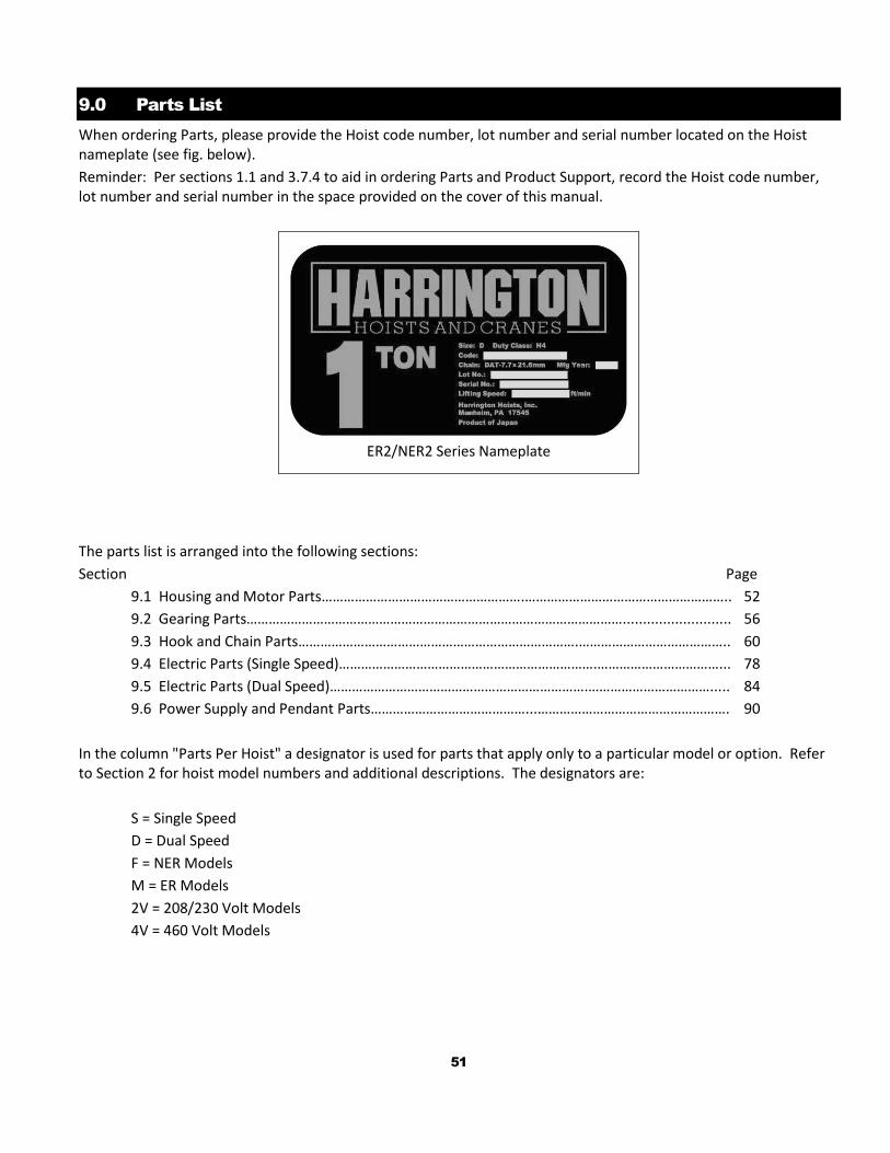
51
9.0 Parts List
When ordering Parts, please provide the Hoist code number, lot number and serial number located on the Hoist nameplate (see fig. below).
Reminder: Per sections 1.1 and 3.7.4 to aid in ordering Parts and Product Support, record the Hoist code number, lot number and serial number in the space provided on the cover of this manual.
ER2/NER2 Series Nameplate
The parts list is arranged into the following sections:
Section Page
9.1 Housing and Motor Parts……………………………………………….……………………………………………….. 52
9.2 Gearing Parts…………………………………………………………………………………………........................... 56
9.3 Hook and Chain Parts………………………………………………………………….………………………………….. 60
9.4 Electric Parts (Single Speed)…………………………………………………………….……………………………... 78
9.5 Electric Parts (Dual Speed)…………………………………………………………….……………………………..... 84
9.6 Power Supply and Pendant Parts……………………………………...……………………………………………. 90
In the column "Parts Per Hoist" a designator is used for parts that apply only to a particular model or option. Refer to Section 2 for hoist model numbers and additional descriptions. The designators are:
S = Single Speed
D = Dual Speed
F = NER Models
M = ER Models
2V = 208/230 Volt Models
4V = 460 Volt Models
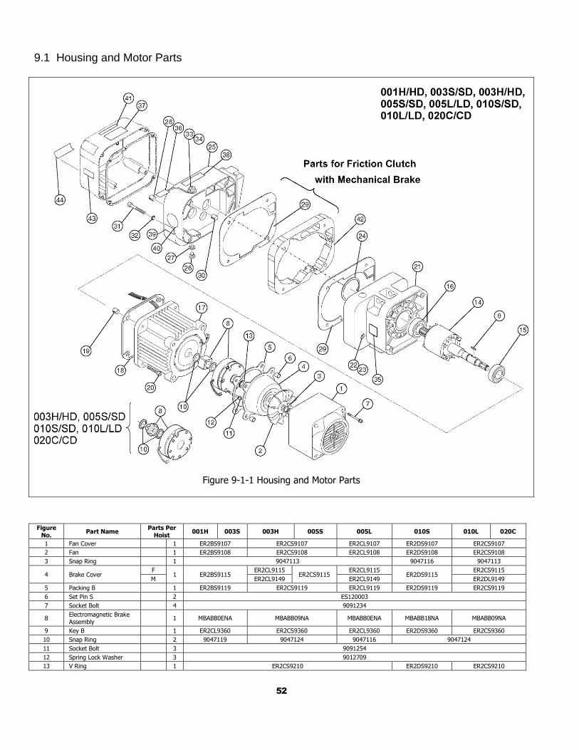
52
9.1 Housing and Motor Parts
Figure 9-1-1 Housing and Motor Parts
Figure No.
Part Name Parts Per
Hoist 001H 003S 003H 005S 005L 010S 010L 020C
1 Fan Cover 1 ER2BS9107 ER2CS9107 ER2CL9107 ER2DS9107 ER2CS9107
2 Fan 1 ER2BS9108 ER2CS9108 ER2CL9108 ER2DS9108 ER2CS9108
3 Snap Ring 1 9047113 9047116 9047113
4 Brake Cover F
1 ER2BS9115 ER2CL9115
ER2CS9115 ER2CL9115
ER2DS9115 ER2CS9115
M ER2CL9149 ER2CL9149 ER2DL9149
5 Packing B 1 ER2BS9119 ER2CS9119 ER2CL9119 ER2DS9119 ER2CS9119
6 Set Pin S 2 ES120003
7 Socket Bolt 4 9091234
8 Electromagnetic Brake Assembly
1 MBABB0ENA MBABB09NA MBABB0ENA MBABB18NA MBABB09NA
9 Key B 1 ER2CL9360 ER2CS9360 ER2CL9360 ER2DS9360 ER2CS9360
10 Snap Ring 2 9047119 9047124 9047116 9047124
11 Socket Bolt 3 9091254
12 Spring Lock Washer 3 9012709
13 V Ring 1 ER2CS9210 ER2DS9210 ER2CS9210
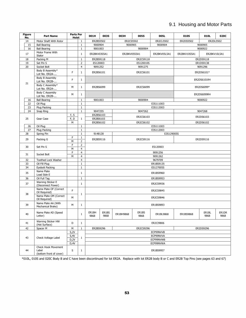
53
9.1 Housing and Motor Parts Figure
No. Part Name
Parts Per Hoist
001H 003S 003H 005S 005L 010S 010L 020C
14 Motor Shaft With Rotor 1 ER2BS5502 ER2CS5502 ER2CL5502 ER2DS5502 ER2DL5502
15 Ball Bearing 1 9000904 9000905 9000904 9000905
16 Ball Bearing 1 9001003 9000904 9000922
17 Motor Frame With Stator
1 ER2BKV03S5A1 ER2BKV05S5A1 ER2BKV05L5A1 ER2BKV10S5A1 ER2BKV10L5A1
18 Packing M 1 ER2BS9118 ER2CS9118 ER2DS9118
19 Set Pin S 2 ES120003 ES120010S ER1DS9138
20 Socket Bolt 4 9091252 9091275 9091296
21
Body B Assembly*
Lot No. ER2A-... F 1 ER2BS6101 ER2CS6101 ER2DS6101*
Body B Assembly
Lot No. ER2B-... F 1 ER2DS6101R4
Body C Assembly*
Lot No. ER2A-... M 1 ER2BS6099 ER2CS6099 ER2DS6099*
Body C Assembly
Lot No. ER2B-... M 1 ER2DS6099R4
16 Ball Bearing 1 9001003 9000904 9000922
22 Oil Plug 1 E3S111003
23 Plug Packing 1 E3S112003
24 Snap Ring 1 9047255 9047262 9047268
25 Gear Case
F, S
1
ER2BS6103 ER2CS6103 ER2DS6103
F, D ER2BI6103
M ER2BS6102 ER2CS6102 ER2DS6102
26 Oil Plug 1 E3S111003
27 Plug Packing 1 E3S112003
28 Spring Pin 1 9148128 E3S129005S
29 Packing G F 1
ER2BS9116 ER2CS9116 ER2DS9116 M 2
30 Set Pin S F 2
ES120003 M 4
31 Socket Bolt F 4 9091256
M 4 9091262
32 Toothed Lock Washer 4 9679709
33 Oil Fill Plug 1 ER1BS9135
34 Eyebolt Packing 1 ES127005S
35 Name Plate
Load Side E 1 ER1BS9960
36 Oil Full Tag 1 ER1BS9953
37 Warning Sticker E
(Disconnect Power) 1 ER2CS9936
38
Name Plate OF (Correct Oil Required)
F
1
ER2CS9845
Name Plate OM (Correct Oil Required)
M ER2CS9846
39 Name Plate AA (With
Mechanical Brake) M 1 ER1BS9893
40 Name Plate AD (Speed
Letter) 1
ER1BH
9868
ER1BS
9868 ER1BH9868
ER1BS
9868 ER1BL9868 ER1BS9868
ER1BL
9868
ER1DR
9868
41 Warning Sticker HW
(Hot Surface) D 1 ER2CI9806
42 Spacer M M 1 ER2BS9296 ER2CS9296 ER2DS9296
43 Check Voltage Label
S,2V
1
ECP99NVVB
S,4V ECP99NVVA
D,2V ECP99NVWB
D,4V ECP99NVWA
44
Check Hook Movement
Label
(bottom front of cover)
S 1 ER1BS9957
*010L, 010S and 020C Body B and C have been discontinued for lot ER2A. Replace with lot ER2B body B or C and ER2B Top Pins (see pages 63 and 67)
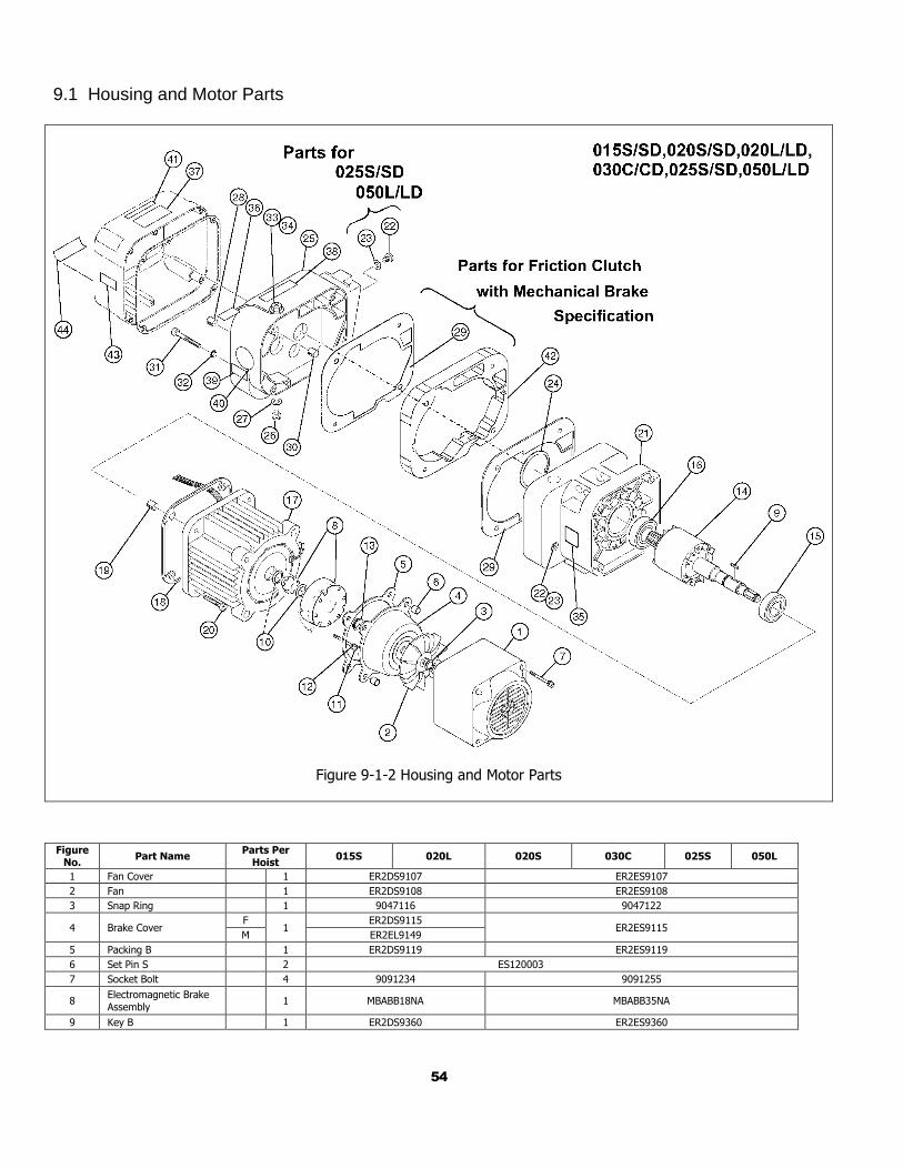
54
9.1 Housing and Motor Parts
Figure 9-1-2 Housing and Motor Parts
Figure No.
Part Name Parts Per
Hoist 015S 020L 020S 030C 025S 050L
1 Fan Cover 1 ER2DS9107 ER2ES9107
2 Fan 1 ER2DS9108 ER2ES9108
3 Snap Ring 1 9047116 9047122
4 Brake Cover F
1 ER2DS9115
ER2ES9115 M ER2EL9149
5 Packing B 1 ER2DS9119 ER2ES9119
6 Set Pin S 2 ES120003
7 Socket Bolt 4 9091234 9091255
8 Electromagnetic Brake Assembly
1 MBABB18NA MBABB35NA
9 Key B 1 ER2DS9360 ER2ES9360
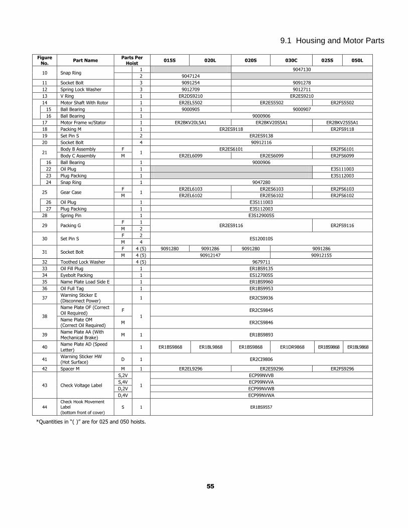
55
9.1 Housing and Motor Parts
Figure
No. Part Name
Parts Per
Hoist 015S 020L 020S 030C 025S 050L
10 Snap Ring 1 9047130
2 9047124
11 Socket Bolt 3 9091254 9091278
12 Spring Lock Washer 3 9012709 9012711
13 V Ring 1 ER2DS9210 ER2ES9210
14 Motor Shaft With Rotor 1 ER2EL5502 ER2ES5502 ER2FS5502
15 Ball Bearing 1 9000905 9000907
16 Ball Bearing 1 9000906
17 Motor Frame w/Stator 1 ER2BKV20L5A1 ER2BKV20S5A1 ER2BKV25S5A1
18 Packing M 1 ER2ES9118 ER2FS9118
19 Set Pin S 2 ER2ES9138
20 Socket Bolt 4 90912116
21 Body B Assembly F
1 ER2ES6101 ER2FS6101
Body C Assembly M ER2EL6099 ER2ES6099 ER2FS6099
16 Ball Bearing 1 9000906
22 Oil Plug 1 E3S111003
23 Plug Packing 1 E3S112003
24 Snap Ring 1 9047280
25 Gear Case F
1 ER2EL6103 ER2ES6103 ER2FS6103
M ER2EL6102 ER2ES6102 ER2FS6102
26 Oil Plug 1 E3S111003
27 Plug Packing 1 E3S112003
28 Spring Pin 1 E3S129005S
29 Packing G F 1
ER2ES9116 ER2FS9116 M 2
30 Set Pin S F 2
ES120010S M 4
31 Socket Bolt F 4 (5) 9091280 9091286 9091280 9091286
M 4 (5) 90912147 90912155
32 Toothed Lock Washer 4 (5) 9679711
33 Oil Fill Plug 1 ER1BS9135
34 Eyebolt Packing 1 ES127005S
35 Name Plate Load Side E 1 ER1BS9960
36 Oil Full Tag 1 ER1BS9953
37 Warning Sticker E
(Disconnect Power) 1 ER2CS9936
38
Name Plate OF (Correct
Oil Required) F
1
ER2CS9845
Name Plate OM (Correct Oil Required)
M ER2CS9846
39 Name Plate AA (With
Mechanical Brake) M 1 ER1BS9893
40 Name Plate AD (Speed
Letter) 1 ER1BS9868 ER1BL9868 ER1BS9868 ER1DR9868 ER1BS9868 ER1BL9868
41 Warning Sticker HW (Hot Surface)
D 1 ER2CI9806
42 Spacer M M 1 ER2EL9296 ER2ES9296 ER2FS9296
43 Check Voltage Label
S,2V
1
ECP99NVVB
S,4V ECP99NVVA
D,2V ECP99NVWB
D,4V ECP99NVWA
44
Check Hook Movement Label
(bottom front of cover)
S 1 ER1BS9557
*Quantities in “( )” are for 025 and 050 hoists.
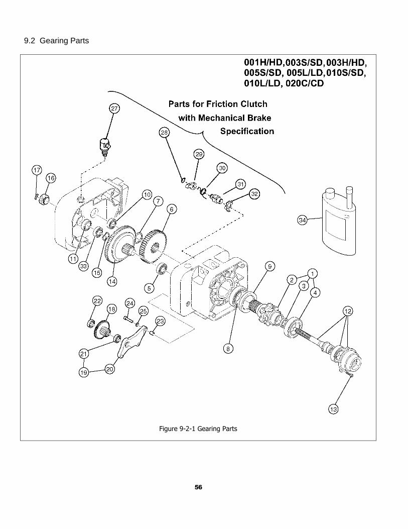
56
9.2 Gearing Parts
Figure 9-2-1 Gearing Parts
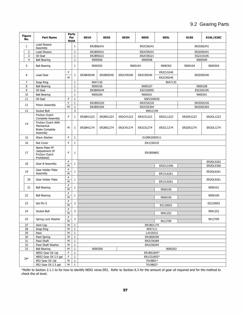
57
9.2 Gearing Parts
Figure No.
Part Name
Parts
Per Hoist
001H 003S 003H 005S 005L 010S 010L/020C
1 Load Sheave Assembly
1 ER2BS6241 ER2CS6241 ER2DS6241
2 Load Sheave 1 ER2BS9241 ER2CS9241 ER2DS9241
3 Oil Seal 1 ER2BS9221 ER2CS9221 ES221010S
4 Ball Bearing 1 9000506 9000508 9000509
5 Ball Bearing 1 9000202 9000104 9000302 9000104 9000304
6 Load Gear F
1 ER2BH9240 ER2BS9240 ER2CH9240 ER2CS9240 ER2CL9240
ER2DS9240 M ER2CS9240
7 Snap Ring 1 9047130 9047135
8 Ball Bearing 1 9000106 9000107 9000108
9 Oil Seal 1 ER2BS9244 ES232005S ES232010S
10 Ball Bearing 1 9000200 9000201 9000301
11 Oil Seal F 1 E6F235003S
12 Pinion Assembly F 1 ER2BS5220 ER2CS5220 ER2DS5220
M 1 ER2BS5304 ER2CS5304 ER2DS5304
13 Socket Bolt 3 90912149
14
Friction Clutch
Complete Assembly F 1 ER2BH1223 ER2BS1223 ER2CH1223 ER2CS1223 ER2CL1223 ER2DS1223 ER2DL1223
Friction Clutch With Mechanical
Brake Complete Assembly
M 1 ER2BH1274 ER2BS1274 ER2CH1274 ER2CS1274 ER2CL1274 ER2DS1274 ER2DL1274
15 Wave Washer F 1 E1DBX20S9311
16 Nut Cover F 1 ER1CS9235
17
Name Plate FP (Adjustment Of
Friction Clutch Prohibited)
F 1 ER1BS9892
18 Gear B Assembly F
1 ER2DL5262
M ER2CL5306 ER2DL5306
19 Gear Holder Plate
Assembly
F 1
ER2DL6261
M ER1CL6261
20 Gear Holder Plate F
1
ER2DL9261 M ER1CL9261
21 Ball Bearing F
1
9000101 M 9000100
22 Ball Bearing F
1
9000100 M 9000100
23 Set Pin S F
2
ES120003 M ES120003
24 Socket Bolt F
3
9091252 M 9091252
25 Spring Lock Washer F
3
9012709 M 9012709
27 Vent Cap M 1 ER1BS1175
28 Snap Ring M 1 9047111
29 Pawl M 1 L4155015
30 Pawl Spring M 1 ER1BS9290
31 Pawl Shaft M 1 ER2CS9289
32 Pawl Shaft Washer M 1 ER2CS9294
33 Ball Bearing M 1 9000300 9000202
34*
NER2 Gear Oil 1qt F 1 ER1BS1855*
NER2 Gear Oil 2.5 gal F 1 ER1CS1855*
ER2 Gear Oil 1qt M 1 7019801*
ER2 Gear Oil 2.5 gal M 1 7019802*
*Refer to Section 2.1.1 to for how to identify NER2 verse ER2. Refer to Section 6.3 for the amount of gear oil required and for the method to check the oil level.
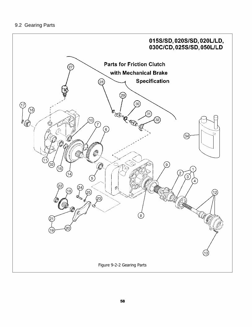
58
9.2 Gearing Parts
Figure 9-2-2 Gearing Parts
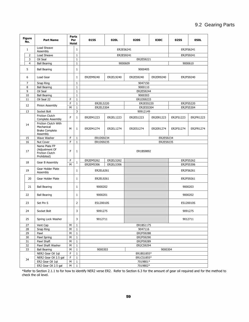
59
9.2 Gearing Parts
Figure
No. Part Name
Parts Per
Hoist
015S 020L 020S 030C 025S 050L
1 Load Sheave Assembly
1 ER2ES6241 ER2FS6241
2 Load Sheave 1 ER2ES9241 ER2FS9241
3 Oil Seal 1 ER2ES9221
4 Ball Bearing 1 9000609 9000610
5 Ball Bearing 1 9000405
6 Load Gear 1 ER2EM9240 ER2EL9240 ER2ES9240 ER2ER9240 ER2FS9240
7 Snap Ring 1 9047150
8 Ball Bearing 1 9000110
9 Oil Seal 1 ER2ES9244
10 Ball Bearing 1 9000303
11 Oil Seal 22 F 1 ER1DS9233
12 Pinion Assembly F 1 ER2EL5220 ER2ES5220 ER2FS5220
M 1 ER2EL5304 ER2ES5304 ER2FS5304
13 Socket Bolt 3 90912149
14
Friction Clutch
Complete Assembly F 1 ER2EM1223 ER2EL1223 ER2ES1223 ER2ER1223 ER2FS1223 ER2FR1223
Friction Clutch With Mechanical
Brake Complete Assembly
M 1 ER2EM1274 ER2EL1274 ER2ES1274 ER2ER1274 ER2FS1274 ER2FR1274
15 Wave Washer F 1 ER1DS9234 ER2ES9234
16 Nut Cover F 1 ER1DS9235 ER2ES9235
17
Name Plate FP (Adjustment Of
Friction Clutch Prohibited)
F 1 ER1BS9892
18 Gear B Assembly F
1 ER2EM5262 ER2EL5262 ER2FS5262
M ER2EM5306 ER2EL5306 ER2FS5306
19 Gear Holder Plate
Assembly 1 ER2EL6261 ER2FS6261
20 Gear Holder Plate 1 ER2EL9261 ER2FS9261
21 Ball Bearing 1 9000202 9000203
22 Ball Bearing 1 9000201 9000202
23 Set Pin S 2 ES120010S ES120010S
24 Socket Bolt 3 9091275 9091275
25 Spring Lock Washer 3 9012711 9012711
27 Vent Cap M 1 ER1BS1175
28 Snap Ring M 1 9047116
29 Pawl M 1 ER2FS9288
30 Pawl Spring M 1 ER2FS9290
31 Pawl Shaft M 1 ER2FS9289
32 Pawl Shaft Washer M 1 ER2CS9294
33 Ball Bearing M 1 9000303 9000304
34
NER2 Gear Oil 1qt F 1 ER1BS1855*
NER2 Gear Oil 2.5 gal F 1 ER1CS1855*
ER2 Gear Oil 1qt M 1 7019801*
ER2 Gear Oil 2.5 gal M 1 7019802*
*Refer to Section 2.1.1 to for how to identify NER2 verse ER2. Refer to Section 6.3 for the amount of gear oil required and for the method to check the oil level.
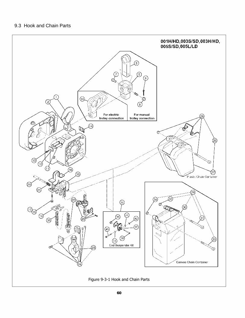
60
9.3 Hook and Chain Parts
Figure 9-3-1 Hook and Chain Parts
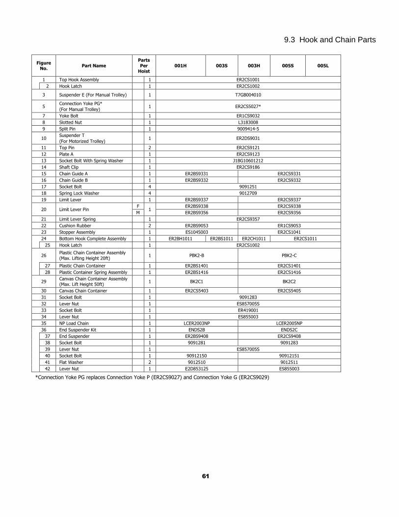
61
9.3 Hook and Chain Parts
Figure No.
Part Name
Parts
Per Hoist
001H 003S 003H 005S 005L
1 Top Hook Assembly 1 ER2CS1001
2 Hook Latch 1 ER2CS1002
3 Suspender E (For Manual Trolley) 1 T7GB004010
5 Connection Yoke PG*
(For Manual Trolley)
1 ER2CS5027*
7 Yoke Bolt 1 ER1CS9032
8 Slotted Nut 1 L3183008
9 Split Pin 1 9009414-5
10 Suspender T
(For Motorized Trolley)
1 ER2DS9031
11 Top Pin 2 ER2CS9121
12 Plate A 1 ER2CS9123
13 Socket Bolt With Spring Washer 1 J1BG10601212
14 Shaft Clip 1 ER2CS9186
15 Chain Guide A 1 ER2BS9331 ER2CS9331
16 Chain Guide B 1 ER2BS9332 ER2CS9332
17 Socket Bolt 4 9091251
18 Spring Lock Washer 4 9012709
19 Limit Lever 1 ER2BS9337 ER2CS9337
20 Limit Lever Pin F
1 ER2BS9338 ER2CS9338
M ER2BS9356 ER2CS9356
21 Limit Lever Spring 1 ER2CS9357
22 Cushion Rubber 2 ER2BS9053 ER1CS9053
23 Stopper Assembly 1 ES1045003 ER2CS1041
24 Bottom Hook Complete Assembly 1 ER2BH1011 ER2BS1011 ER2CH1011 ER2CS1011
25 Hook Latch 1 ER2CS1002
26 Plastic Chain Container Assembly
(Max. Lifting Height 20ft)
1 PBK2-B PBK2-C
27 Plastic Chain Container 1 ER2BS1401 ER2CS1401
28 Plastic Container Spring Assembly 1 ER2BS1416 ER2CS1416
29 Canvas Chain Container Assembly (Max. Lift Height 50ft)
1 BK2C1 BK2C2
30 Canvas Chain Container 1 ER2CS5403 ER2CS5405
31 Socket Bolt 1 9091283
32 Lever Nut 1 ES857005S
33 Socket Bolt 1 ER419001
34 Lever Nut 1 ES855003
35 NP Load Chain 1 LCER2003NP LCER2005NP
36 End Suspender Kit 1 ENDS2B ENDS2C
37 End Suspender 1 ER2BS9408 ER2CS9408
38 Socket Bolt 1 9091281 9091283
39 Lever Nut 1 ES857005S
40 Socket Bolt 1 90912150 90912151
41 Flat Washer 2 9012510 9012511
42 Lever Nut 1 E2D853125 ES855003
*Connection Yoke PG replaces Connection Yoke P (ER2CS9027) and Connection Yoke G (ER2CS9029)
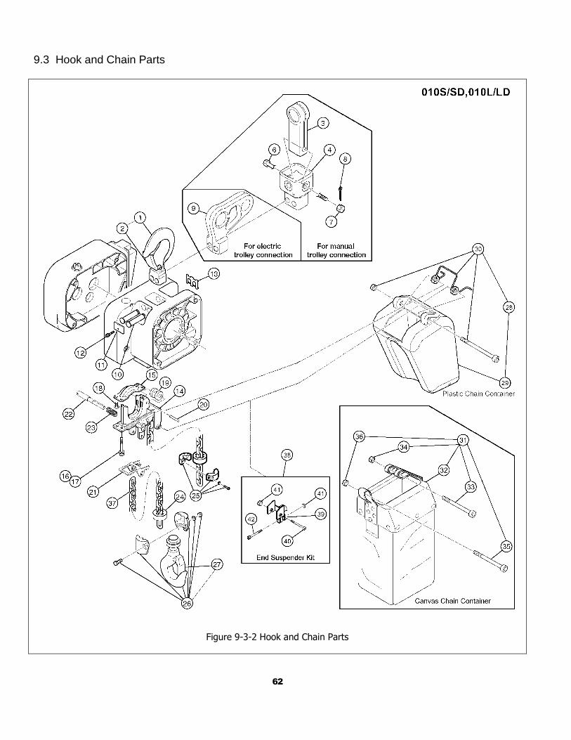
62
9.3 Hook and Chain Parts
Figure 9-3-2 Hook and Chain Parts
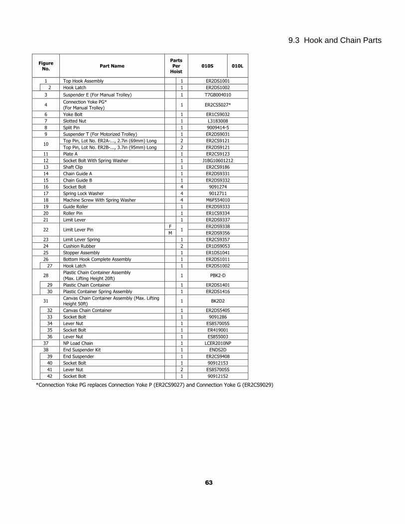
63
9.3 Hook and Chain Parts
Figure No.
Part Name Parts Per
Hoist 010S 010L
1 Top Hook Assembly 1 ER2DS1001
2 Hook Latch 1 ER2DS1002
3 Suspender E (For Manual Trolley) 1 T7GB004010
4 Connection Yoke PG*
(For Manual Trolley)
1 ER2CS5027*
6 Yoke Bolt 1 ER1CS9032
7 Slotted Nut 1 L3183008
8 Split Pin 1 9009414-5
9 Suspender T (For Motorized Trolley) 1 ER2DS9031
10 Top Pin, Lot No. ER2A-..., 2.7in (69mm) Long 2 ER2CS9121
Top Pin, Lot No. ER2B-..., 3.7in (95mm) Long 2 ER2DS9121
11 Plate A 1 ER2CS9123
12 Socket Bolt With Spring Washer 1 J1BG10601212
13 Shaft Clip 1 ER2CS9186
14 Chain Guide A 1 ER2DS9331
15 Chain Guide B 1 ER2DS9332
16 Socket Bolt 4 9091274
17 Spring Lock Washer 4 9012711
18 Machine Screw With Spring Washer 4 M6F554010
19 Guide Roller 1 ER2DS9333
20 Roller Pin 1 ER1CS9334
21 Limit Lever 1 ER2DS9337
22 Limit Lever Pin F
1 ER2DS9338
M ER2DS9356
23 Limit Lever Spring 1 ER2CS9357
24 Cushion Rubber 2 ER1DS9053
25 Stopper Assembly 1 ER1DS1041
26 Bottom Hook Complete Assembly 1 ER2DS1011
27 Hook Latch 1 ER2DS1002
28 Plastic Chain Container Assembly
(Max. Lifting Height 20ft)
1 PBK2-D
29 Plastic Chain Container 1 ER2DS1401
30 Plastic Container Spring Assembly 1 ER2DS1416
31 Canvas Chain Container Assembly (Max. Lifting
Height 50ft)
1 BK2D2
32 Canvas Chain Container 1 ER2DS5405
33 Socket Bolt 1 9091286
34 Lever Nut 1 ES857005S
35 Socket Bolt 1 ER419001
36 Lever Nut 1 ES855003
37 NP Load Chain 1 LCER2010NP
38 End Suspender Kit 1 ENDS2D
39 End Suspender 1 ER2CS9408
40 Socket Bolt 1 90912153
41 Lever Nut 2 ES857005S
42 Socket Bolt 1 90912152
*Connection Yoke PG replaces Connection Yoke P (ER2CS9027) and Connection Yoke G (ER2CS9029)
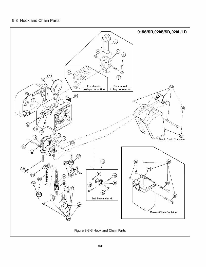
64
9.3 Hook and Chain Parts
Figure 9-3-3 Hook and Chain Parts
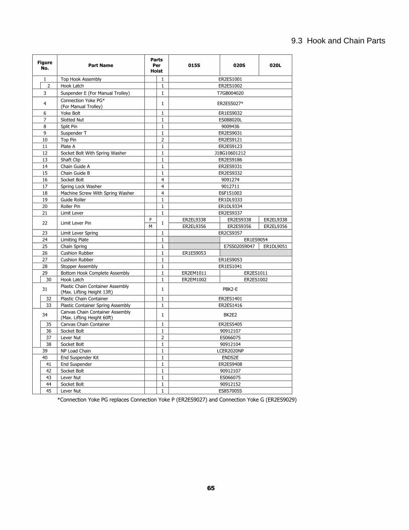
65
9.3 Hook and Chain Parts
Figure
No. Part Name
Parts Per
Hoist 015S 020S 020L
1 Top Hook Assembly 1 ER2ES1001
2 Hook Latch 1 ER2ES1002
3 Suspender E (For Manual Trolley) 1 T7GB004020
4 Connection Yoke PG*
(For Manual Trolley)
1 ER2ES5027*
6 Yoke Bolt 1 ER1ES9032
7 Slotted Nut 1 ES088020L
8 Split Pin 1 9009436
9 Suspender T 1 ER2ES9031
10 Top Pin 2 ER2ES9121
11 Plate A 1 ER2ES9123
12 Socket Bolt With Spring Washer 1 J1BG10601212
13 Shaft Clip 1 ER2ES9186
14 Chain Guide A 1 ER2ES9331
15 Chain Guide B 1 ER2ES9332
16 Socket Bolt 4 9091274
17 Spring Lock Washer 4 9012711
18 Machine Screw With Spring Washer 4 E6F151003
19 Guide Roller 1 ER1DL9333
20 Roller Pin 1 ER1DL9334
21 Limit Lever 1 ER2ES9337
22 Limit Lever Pin F
1 ER2EL9338 ER2ES9338 ER2EL9338
M ER2EL9356 ER2ES9356 ER2EL9356
23 Limit Lever Spring 1 ER2CS9357
24 Limiting Plate 1 ER1ES9054
25 Chain Spring 1 E7SS020S9047 ER1DL9051
26 Cushion Rubber 1 ER1ES9053
27 Cushion Rubber 1 ER1ES9053
28 Stopper Assembly 1 ER1ES1041
29 Bottom Hook Complete Assembly 1 ER2EM1011 ER2ES1011
30 Hook Latch 1 ER2EM1002 ER2ES1002
31 Plastic Chain Container Assembly
(Max. Lifting Height 13ft)
1 PBK2-E
32 Plastic Chain Container 1 ER2ES1401
33 Plastic Container Spring Assembly 1 ER2ES1416
34 Canvas Chain Container Assembly (Max. Lifting Height 60ft)
1 BK2E2
35 Canvas Chain Container 1 ER2ES5405
36 Socket Bolt 1 90912107
37 Lever Nut 2 ES066075
38 Socket Bolt 1 90912104
39 NP Load Chain 1 LCER2020NP
40 End Suspender Kit 1 ENDS2E
41 End Suspender 1 ER2ES9408
42 Socket Bolt 1 90912107
43 Lever Nut 1 ES066075
44 Socket Bolt 1 90912152
45 Lever Nut 1 ES857005S
*Connection Yoke PG replaces Connection Yoke P (ER2ES9027) and Connection Yoke G (ER2ES9029)
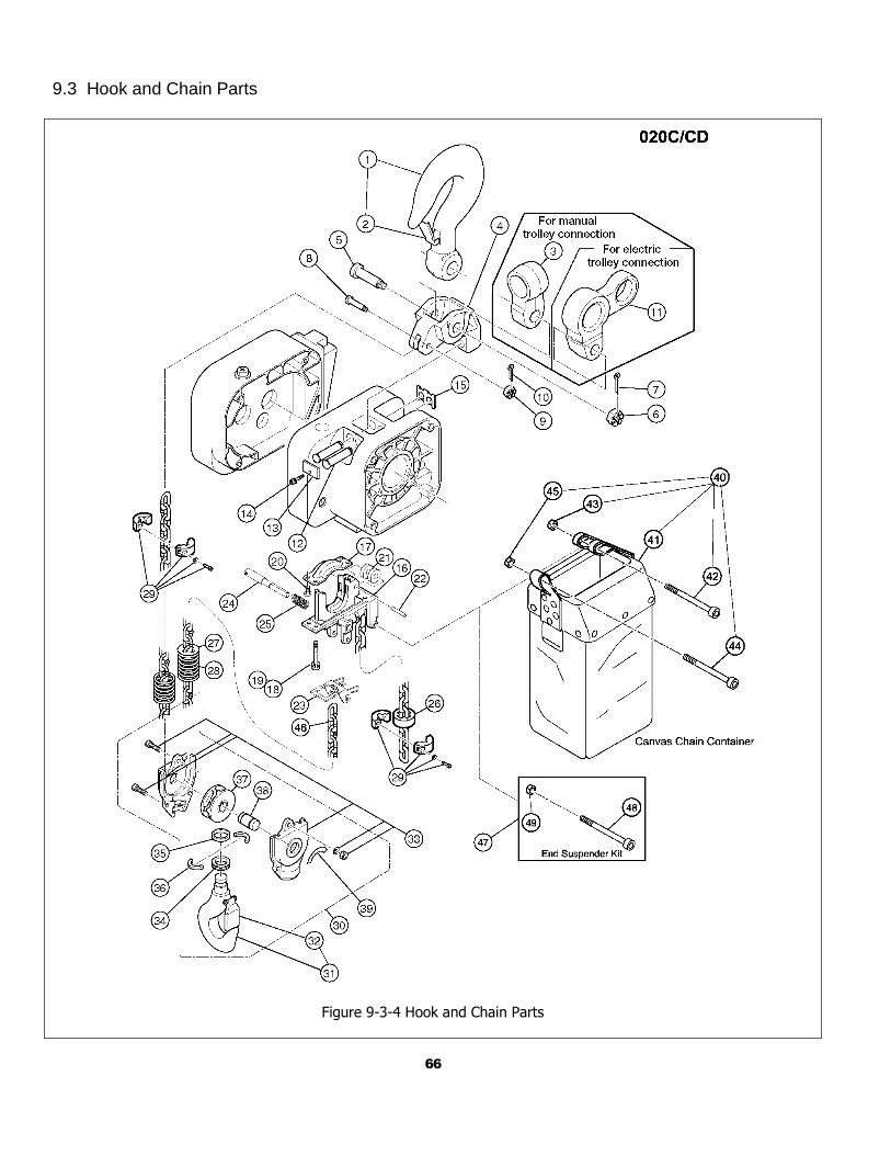
66
9.3 Hook and Chain Parts
Figure 9-3-4 Hook and Chain Parts
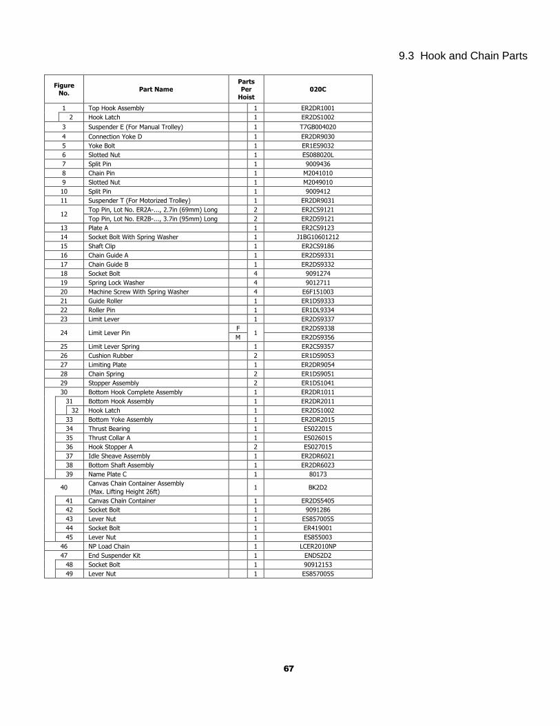
67
9.3 Hook and Chain Parts
Figure No.
Part Name Parts Per
Hoist
020C
1 Top Hook Assembly 1 ER2DR1001
2 Hook Latch 1 ER2DS1002
3 Suspender E (For Manual Trolley) 1 T7GB004020
4 Connection Yoke D 1 ER2DR9030
5 Yoke Bolt 1 ER1ES9032
6 Slotted Nut 1 ES088020L
7 Split Pin 1 9009436
8 Chain Pin 1 M2041010
9 Slotted Nut 1 M2049010
10 Split Pin 1 9009412
11 Suspender T (For Motorized Trolley) 1 ER2DR9031
12 Top Pin, Lot No. ER2A-..., 2.7in (69mm) Long 2 ER2CS9121
Top Pin, Lot No. ER2B-..., 3.7in (95mm) Long 2 ER2DS9121
13 Plate A 1 ER2CS9123
14 Socket Bolt With Spring Washer 1 J1BG10601212
15 Shaft Clip 1 ER2CS9186
16 Chain Guide A 1 ER2DS9331
17 Chain Guide B 1 ER2DS9332
18 Socket Bolt 4 9091274
19 Spring Lock Washer 4 9012711
20 Machine Screw With Spring Washer 4 E6F151003
21 Guide Roller 1 ER1DS9333
22 Roller Pin 1 ER1DL9334
23 Limit Lever 1 ER2DS9337
24 Limit Lever Pin F
1 ER2DS9338
M ER2DS9356
25 Limit Lever Spring 1 ER2CS9357
26 Cushion Rubber 2 ER1DS9053
27 Limiting Plate 1 ER2DR9054
28 Chain Spring 2 ER1DS9051
29 Stopper Assembly 2 ER1DS1041
30 Bottom Hook Complete Assembly 1 ER2DR1011
31 Bottom Hook Assembly 1 ER2DR2011
32 Hook Latch 1 ER2DS1002
33 Bottom Yoke Assembly 1 ER2DR2015
34 Thrust Bearing 1 ES022015
35 Thrust Collar A 1 ES026015
36 Hook Stopper A 2 ES027015
37 Idle Sheave Assembly 1 ER2DR6021
38 Bottom Shaft Assembly 1 ER2DR6023
39 Name Plate C 1 80173
40 Canvas Chain Container Assembly
(Max. Lifting Height 26ft)
1 BK2D2
41 Canvas Chain Container 1 ER2DS5405
42 Socket Bolt 1 9091286
43 Lever Nut 1 ES857005S
44 Socket Bolt 1 ER419001
45 Lever Nut 1 ES855003
46 NP Load Chain 1 LCER2010NP
47 End Suspender Kit 1 ENDS2D2
48 Socket Bolt 1 90912153
49 Lever Nut 1 ES857005S
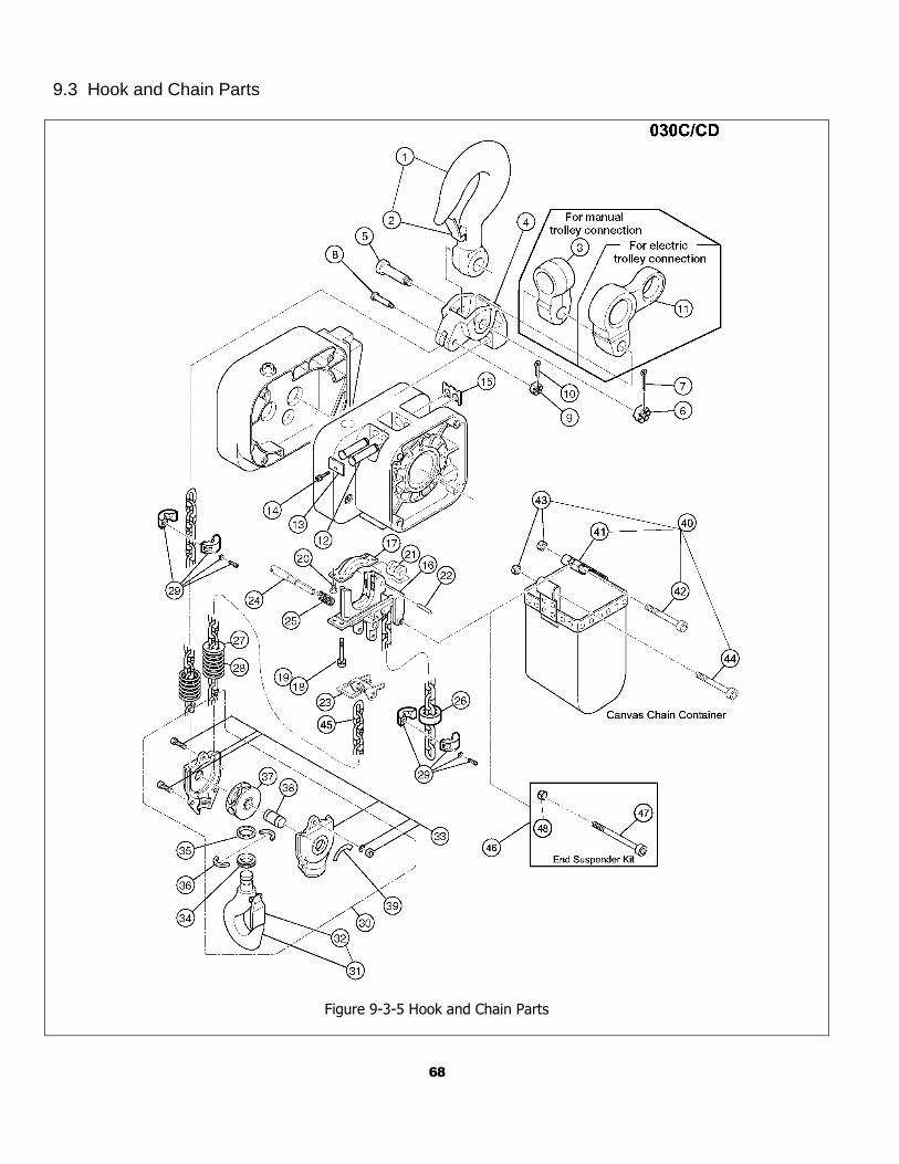
68
9.3 Hook and Chain Parts
Figure 9-3-5 Hook and Chain Parts
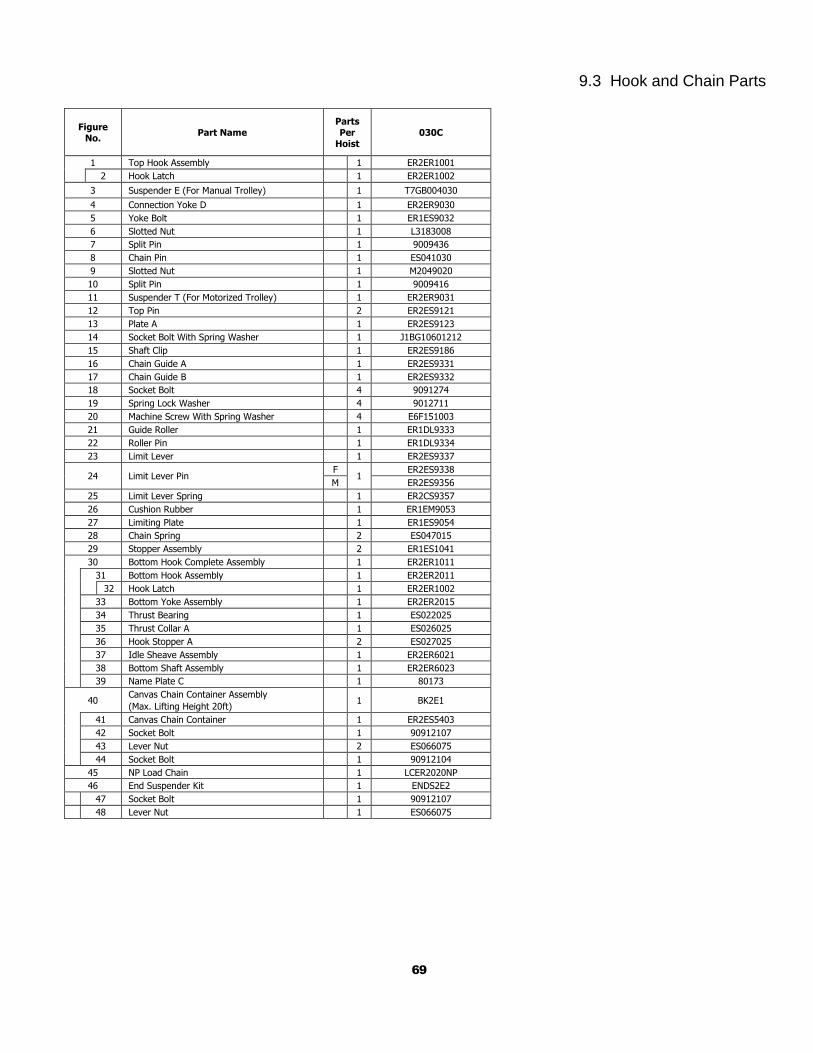
69
9.3 Hook and Chain Parts
Figure No.
Part Name Parts Per
Hoist 030C
1 Top Hook Assembly 1 ER2ER1001
2 Hook Latch 1 ER2ER1002
3 Suspender E (For Manual Trolley) 1 T7GB004030
4 Connection Yoke D 1 ER2ER9030
5 Yoke Bolt 1 ER1ES9032
6 Slotted Nut 1 L3183008
7 Split Pin 1 9009436
8 Chain Pin 1 ES041030
9 Slotted Nut 1 M2049020
10 Split Pin 1 9009416
11 Suspender T (For Motorized Trolley) 1 ER2ER9031
12 Top Pin 2 ER2ES9121
13 Plate A 1 ER2ES9123
14 Socket Bolt With Spring Washer 1 J1BG10601212
15 Shaft Clip 1 ER2ES9186
16 Chain Guide A 1 ER2ES9331
17 Chain Guide B 1 ER2ES9332
18 Socket Bolt 4 9091274
19 Spring Lock Washer 4 9012711
20 Machine Screw With Spring Washer 4 E6F151003
21 Guide Roller 1 ER1DL9333
22 Roller Pin 1 ER1DL9334
23 Limit Lever 1 ER2ES9337
24 Limit Lever Pin F
1 ER2ES9338
M ER2ES9356
25 Limit Lever Spring 1 ER2CS9357
26 Cushion Rubber 1 ER1EM9053
27 Limiting Plate 1 ER1ES9054
28 Chain Spring 2 ES047015
29 Stopper Assembly 2 ER1ES1041
30 Bottom Hook Complete Assembly 1 ER2ER1011
31 Bottom Hook Assembly 1 ER2ER2011
32 Hook Latch 1 ER2ER1002
33 Bottom Yoke Assembly 1 ER2ER2015
34 Thrust Bearing 1 ES022025
35 Thrust Collar A 1 ES026025
36 Hook Stopper A 2 ES027025
37 Idle Sheave Assembly 1 ER2ER6021
38 Bottom Shaft Assembly 1 ER2ER6023
39 Name Plate C 1 80173
40 Canvas Chain Container Assembly
(Max. Lifting Height 20ft)
1 BK2E1
41 Canvas Chain Container 1 ER2ES5403
42 Socket Bolt 1 90912107
43 Lever Nut 2 ES066075
44 Socket Bolt 1 90912104
45 NP Load Chain 1 LCER2020NP
46 End Suspender Kit 1 ENDS2E2
47 Socket Bolt 1 90912107
48 Lever Nut 1 ES066075
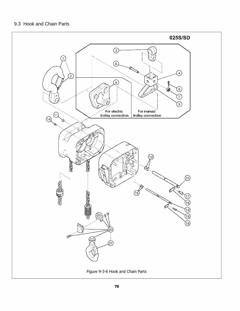
70
9.3 Hook and Chain Parts
Figure 9-3-6 Hook and Chain Parts
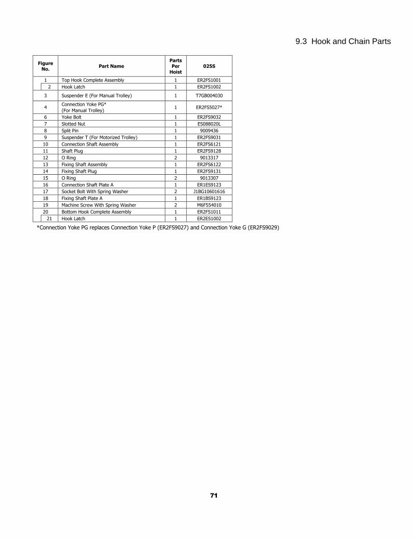
71
9.3 Hook and Chain Parts
Figure No.
Part Name Parts Per
Hoist
025S
1 Top Hook Complete Assembly 1 ER2FS1001
2 Hook Latch 1 ER2FS1002
3 Suspender E (For Manual Trolley) 1 T7GB004030
4 Connection Yoke PG*
(For Manual Trolley) 1 ER2FS5027*
6 Yoke Bolt 1 ER2FS9032
7 Slotted Nut 1 ES088020L
8 Split Pin 1 9009436
9 Suspender T (For Motorized Trolley) 1 ER2FS9031
10 Connection Shaft Assembly 1 ER2FS6121
11 Shaft Plug 1 ER2FS9128
12 O Ring 2 9013317
13 Fixing Shaft Assembly 1 ER2FS6122
14 Fixing Shaft Plug 1 ER2FS9131
15 O Ring 2 9013307
16 Connection Shaft Plate A 1 ER1ES9123
17 Socket Bolt With Spring Washer 2 J1BG10601616
18 Fixing Shaft Plate A 1 ER1BS9123
19 Machine Screw With Spring Washer 2 M6F554010
20 Bottom Hook Complete Assembly 1 ER2FS1011
21 Hook Latch 1 ER2ES1002
*Connection Yoke PG replaces Connection Yoke P (ER2FS9027) and Connection Yoke G (ER2FS9029)

72
9.3 Hook and Chain Parts
Figure 9-3-7 Hook and Chain Parts
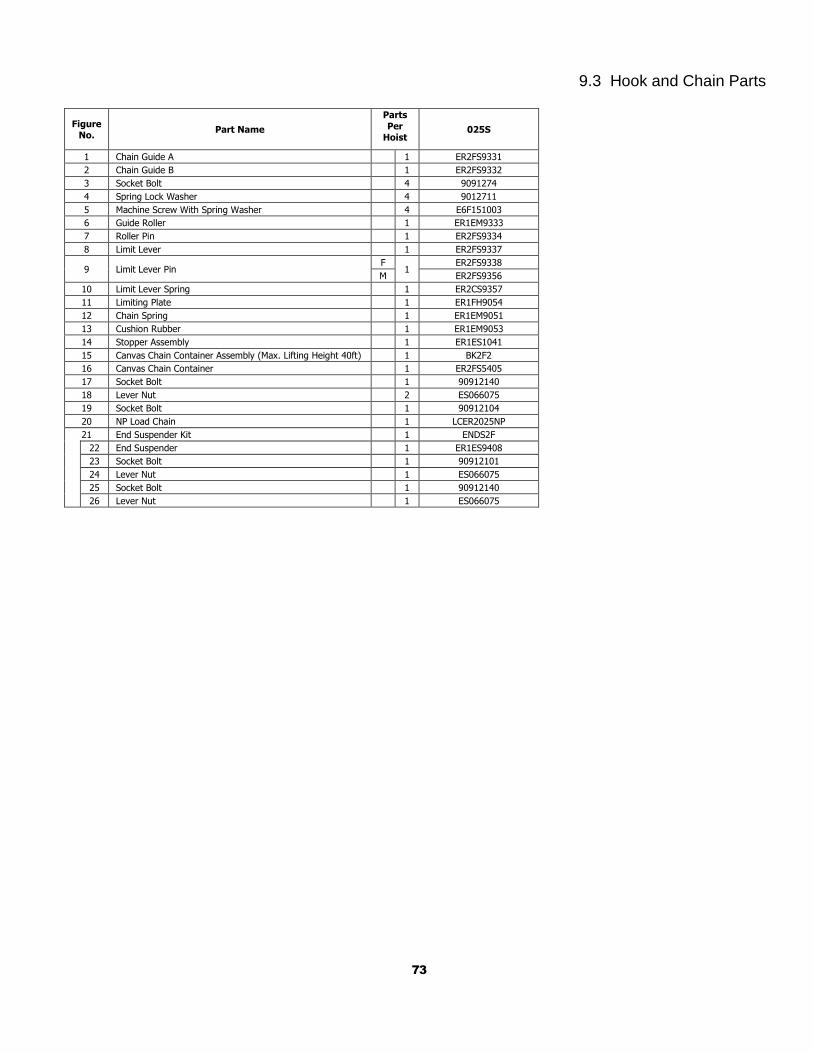
73
9.3 Hook and Chain Parts
Figure No.
Part Name
Parts
Per Hoist
025S
1 Chain Guide A 1 ER2FS9331
2 Chain Guide B 1 ER2FS9332
3 Socket Bolt 4 9091274
4 Spring Lock Washer 4 9012711
5 Machine Screw With Spring Washer 4 E6F151003
6 Guide Roller 1 ER1EM9333
7 Roller Pin 1 ER2FS9334
8 Limit Lever 1 ER2FS9337
9 Limit Lever Pin F
1 ER2FS9338
M ER2FS9356
10 Limit Lever Spring 1 ER2CS9357
11 Limiting Plate 1 ER1FH9054
12 Chain Spring 1 ER1EM9051
13 Cushion Rubber 1 ER1EM9053
14 Stopper Assembly 1 ER1ES1041
15 Canvas Chain Container Assembly (Max. Lifting Height 40ft) 1 BK2F2
16 Canvas Chain Container 1 ER2FS5405
17 Socket Bolt 1 90912140
18 Lever Nut 2 ES066075
19 Socket Bolt 1 90912104
20 NP Load Chain 1 LCER2025NP
21 End Suspender Kit 1 ENDS2F
22 End Suspender 1 ER1ES9408
23 Socket Bolt 1 90912101
24 Lever Nut 1 ES066075
25 Socket Bolt 1 90912140
26 Lever Nut 1 ES066075
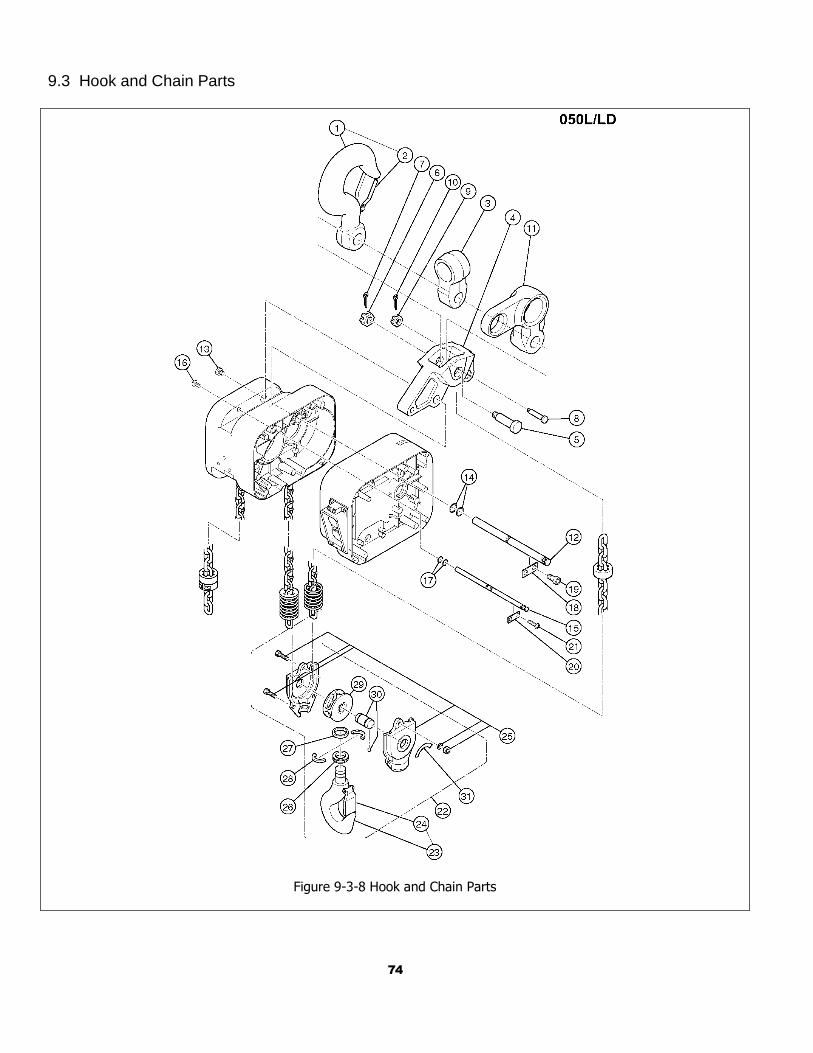
74
9.3 Hook and Chain Parts
Figure 9-3-8 Hook and Chain Parts
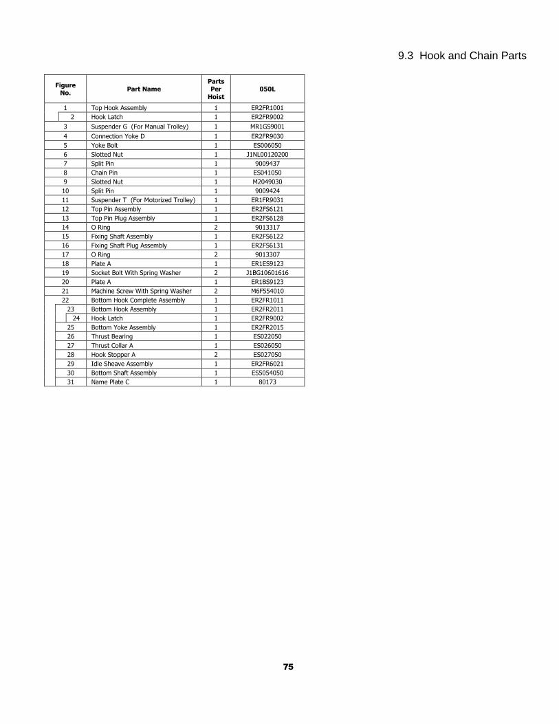
75
9.3 Hook and Chain Parts
Figure No.
Part Name Parts Per
Hoist
050L
1 Top Hook Assembly 1 ER2FR1001
2 Hook Latch 1 ER2FR9002
3 Suspender G (For Manual Trolley) 1 MR1GS9001
4 Connection Yoke D 1 ER2FR9030
5 Yoke Bolt 1 ES006050
6 Slotted Nut 1 J1NL00120200
7 Split Pin 1 9009437
8 Chain Pin 1 ES041050
9 Slotted Nut 1 M2049030
10 Split Pin 1 9009424
11 Suspender T (For Motorized Trolley) 1 ER1FR9031
12 Top Pin Assembly 1 ER2FS6121
13 Top Pin Plug Assembly 1 ER2FS6128
14 O Ring 2 9013317
15 Fixing Shaft Assembly 1 ER2FS6122
16 Fixing Shaft Plug Assembly 1 ER2FS6131
17 O Ring 2 9013307
18 Plate A 1 ER1ES9123
19 Socket Bolt With Spring Washer 2 J1BG10601616
20 Plate A 1 ER1BS9123
21 Machine Screw With Spring Washer 2 M6F554010
22 Bottom Hook Complete Assembly 1 ER2FR1011
23 Bottom Hook Assembly 1 ER2FR2011
24 Hook Latch 1 ER2FR9002
25 Bottom Yoke Assembly 1 ER2FR2015
26 Thrust Bearing 1 ES022050
27 Thrust Collar A 1 ES026050
28 Hook Stopper A 2 ES027050
29 Idle Sheave Assembly 1 ER2FR6021
30 Bottom Shaft Assembly 1 ES5054050
31 Name Plate C 1 80173
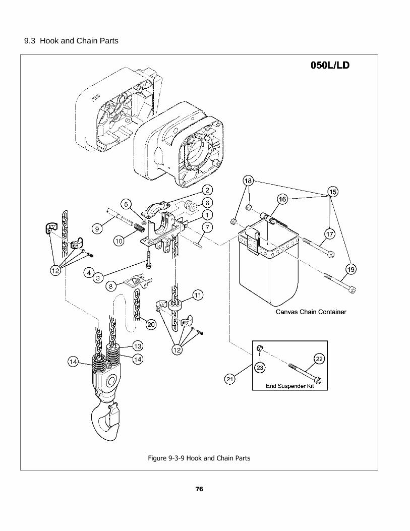
76
9.3 Hook and Chain Parts
Figure 9-3-9 Hook and Chain Parts
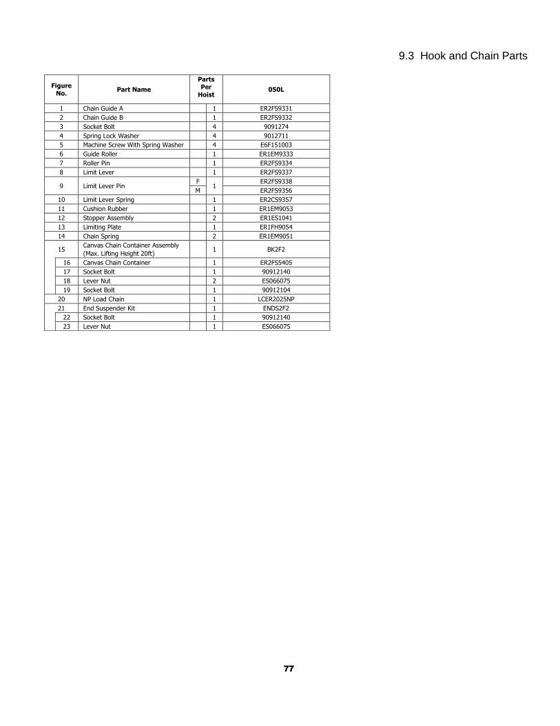
77
9.3 Hook and Chain Parts
Figure No.
Part Name
Parts Per
Hoist 050L
1 Chain Guide A 1 ER2FS9331
2 Chain Guide B 1 ER2FS9332
3 Socket Bolt 4 9091274
4 Spring Lock Washer 4 9012711
5 Machine Screw With Spring Washer 4 E6F151003
6 Guide Roller 1 ER1EM9333
7 Roller Pin 1 ER2FS9334
8 Limit Lever 1 ER2FS9337
9 Limit Lever Pin F
1 ER2FS9338
M ER2FS9356
10 Limit Lever Spring 1 ER2CS9357
11 Cushion Rubber 1 ER1EM9053
12 Stopper Assembly 2 ER1ES1041
13 Limiting Plate 1 ER1FH9054
14 Chain Spring 2 ER1EM9051
15 Canvas Chain Container Assembly
(Max. Lifting Height 20ft)
1 BK2F2
16 Canvas Chain Container 1 ER2FS5405
17 Socket Bolt 1 90912140
18 Lever Nut 2 ES066075
19 Socket Bolt 1 90912104
20 NP Load Chain 1 LCER2025NP
21 End Suspender Kit 1 ENDS2F2
22 Socket Bolt 1 90912140
23 Lever Nut 1 ES066075
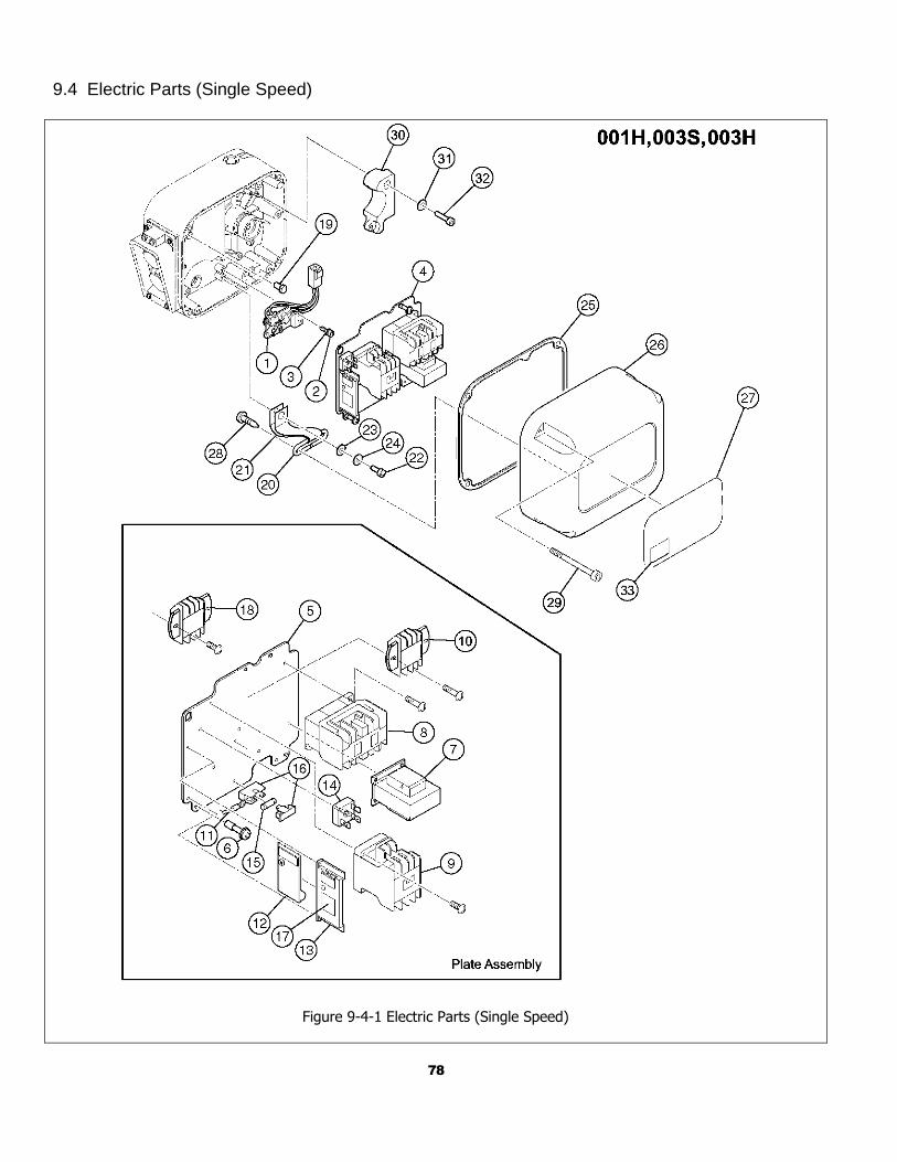
78
9.4 Electric Parts (Single Speed)
Figure 9-4-1 Electric Parts (Single Speed)
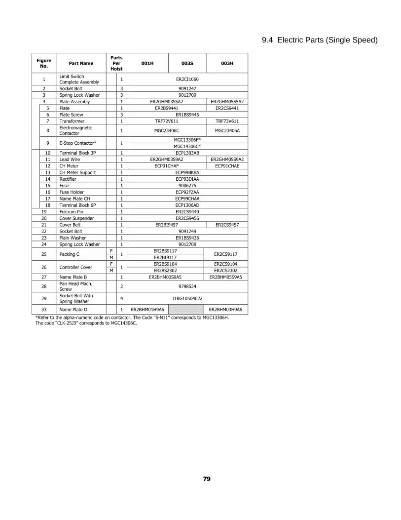
79
9.4 Electric Parts (Single Speed)
Figure
No. Part Name
Parts
Per Hoist
001H 003S 003H
1 Limit Switch Complete Assembly
1 ER2CI1060
2 Socket Bolt 3 9091247
3 Spring Lock Washer 3 9012709
4 Plate Assembly 1 ER2GHM03S5A2 ER2GHM05S5A2
5 Plate 1 ER2BS9441 ER2CS9441
6 Plate Screw 3 ER1BS9445
7 Transformer 1 TRF72V611 TRF73V611
8 Electromagnetic
Contactor 1 MGC23406C MGC23406A
9 E-Stop Contactor* 1 MGC13306F*
MGC14306C*
10 Terminal Block 3P 1 ECP1303AB
11 Lead Wire 1 ER2GHM03S9A2 ER2GHM05S9A2
12 CH Meter 1 ECP91CHAF ECP91CHAE
13 CH Meter Support 1 ECP99BKBA
14 Rectifier 1 ECP93DIAA
15 Fuse 1 9006275
16 Fuse Holder 1 ECP92FZAA
17 Name Plate CH 1 ECP99CHAA
18 Terminal Block 6P 1 ECP1306AD
19 Fulcrum Pin 1 ER2CS9449
20 Cover Suspender 1 ER2CS9456
21 Cover Belt 1 ER2BI9457 ER2CS9457
22 Socket Bolt 1 9091249
23 Plain Washer 1 ER1BS9436
24 Spring Lock Washer 1 9012709
25 Packing C F
1 ER2BS9117
ER2CS9117 M ER2BI9117
26 Controller Cover F
1 ER2BS9104 ER2CS9104
M ER2BS2302 ER2CS2302
27 Name Plate B 1 ER2BHM03S9A5 ER2BHM05S9A5
28 Pan Head Mach. Screw
2 9798534
29 Socket Bolt With
Spring Washer 4 J1BG10504022
33 Name Plate D 1 ER2BHM01H9A6 ER2BHM03H9A6
*Refer to the alpha-numeric code on contactor. The Code “S-N11” corresponds to MGC13306H. The code “CLK-25J3” corresponds to MGC14306C.
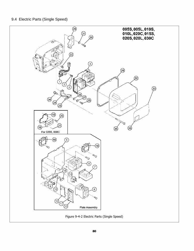
80
9.4 Electric Parts (Single Speed)
Figure 9-4-2 Electric Parts (Single Speed)
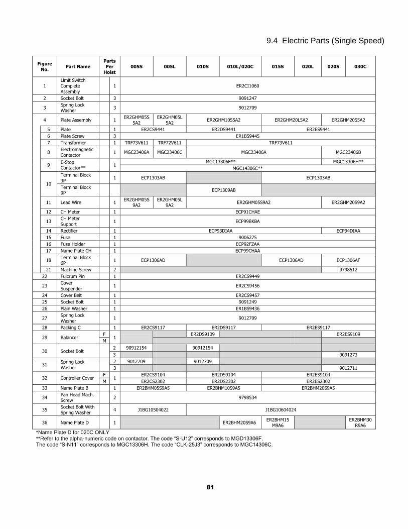
81
9.4 Electric Parts (Single Speed)
Figure
No. Part Name
Parts Per
Hoist
005S 005L 010S 010L/020C 015S 020L 020S 030C
1 Limit Switch
Complete Assembly
1 ER2CI1060
2 Socket Bolt 3 9091247
3 Spring Lock Washer
3 9012709
4 Plate Assembly 1 ER2GHM05S
5A2
ER2GHM05L
5A2 ER2GHM10S5A2 ER2GHM20L5A2 ER2GHM20S5A2
5 Plate 1 ER2CS9441 ER2DS9441 ER2ES9441
6 Plate Screw 3 ER1BS9445
7 Transformer 1 TRF73V611 TRF72V611 TRF73V611
8 Electromagnetic
Contactor 1 MGC23406A MGC23406C MGC23406A MGC23406B
9 E-Stop Contactor**
1 MGC13306F** MGC13306H**
MGC14306C**
10
Terminal Block
3P 1 ECP1303AB ECP1303AB
Terminal Block 9P
ECP1309AB
11 Lead Wire 1 ER2GHM05S
9A2 ER2GHM05L
9A2 ER2GHM05S9A2 ER2GHM20S9A2
12 CH Meter 1 ECP91CHAE
13 CH Meter
Support 1 ECP99BKBA
14 Rectifier 1 ECP93DIAA ECP94DIAA
15 Fuse 1 9006275
16 Fuse Holder 1 ECP92FZAA
17 Name Plate CH 1 ECP99CHAA
18 Terminal Block
6P 1 ECP1306AD ECP1306AD ECP1306AF
21 Machine Screw 2 9798512
22 Fulcrum Pin 1 ER2CS9449
23 Cover
Suspender 1 ER2CS9456
24 Cover Belt 1 ER2CS9457
25 Socket Bolt 1 9091249
26 Plain Washer 1 ER1BS9436
27 Spring Lock
Washer 1 9012709
28 Packing C 1 ER2CS9117 ER2DS9117 ER2ES9117
29 Balancer F
1 ER2DS9109 ER2ES9109
M
30 Socket Bolt 2 90912154 90912154
3 9091273
31 Spring Lock
Washer
2 9012709 9012709
3 9012711
32 Controller Cover F
1 ER2CS9104 ER2DS9104 ER2ES9104
M ER2CS2302 ER2DS2302 ER2ES2302
33 Name Plate B 1 ER2BHM05S9A5 ER2BHM10S9A5 ER2BHM20S9A5
34 Pan Head Mach. Screw
2 9798534
35 Socket Bolt With Spring Washer
4 J1BG10504022 J1BG10604024
36 Name Plate D 1 ER2BHM20S9A6 ER2BHM15
M9A6
ER2BHM30
R9A6
*Name Plate D for 020C ONLY **Refer to the alpha-numeric code on contactor. The code “S-U12” corresponds to MGD13306F. The code “S-N11” corresponds to MGC13306H. The code “CLK-25J3” corresponds to MGC14306C.
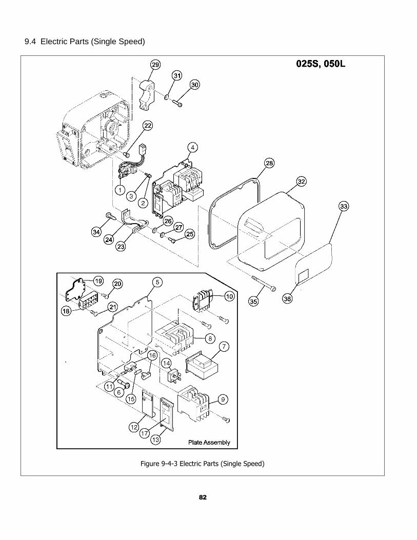
82
9.4 Electric Parts (Single Speed)
Figure 9-4-3 Electric Parts (Single Speed)
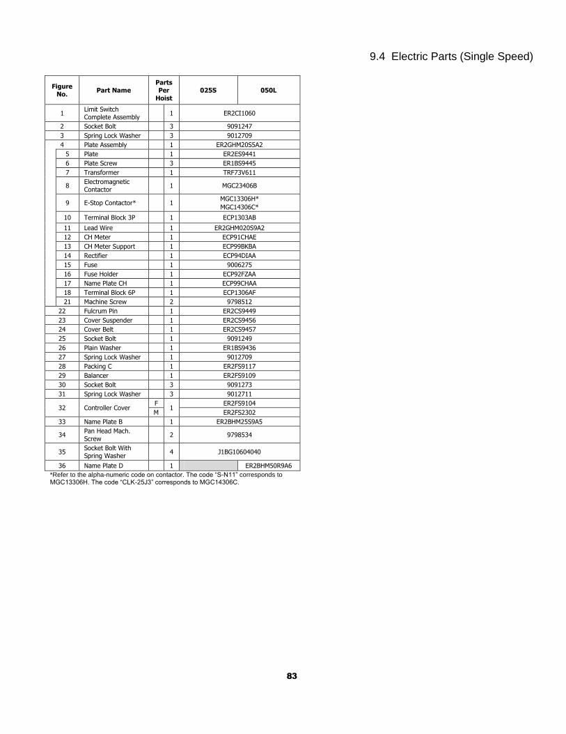
83
9.4 Electric Parts (Single Speed)
Figure No.
Part Name Parts Per
Hoist
025S 050L
1 Limit Switch Complete Assembly
1 ER2CI1060
2 Socket Bolt 3 9091247
3 Spring Lock Washer 3 9012709
4 Plate Assembly 1 ER2GHM20S5A2
5 Plate 1 ER2ES9441
6 Plate Screw 3 ER1BS9445
7 Transformer 1 TRF73V611
8 Electromagnetic Contactor
1 MGC23406B
9 E-Stop Contactor* 1 MGC13306H*
MGC14306C*
10 Terminal Block 3P 1 ECP1303AB
11 Lead Wire 1 ER2GHM020S9A2
12 CH Meter 1 ECP91CHAE
13 CH Meter Support 1 ECP99BKBA
14 Rectifier 1 ECP94DIAA
15 Fuse 1 9006275
16 Fuse Holder 1 ECP92FZAA
17 Name Plate CH 1 ECP99CHAA
18 Terminal Block 6P 1 ECP1306AF
21 Machine Screw 2 9798512
22 Fulcrum Pin 1 ER2CS9449
23 Cover Suspender 1 ER2CS9456
24 Cover Belt 1 ER2CS9457
25 Socket Bolt 1 9091249
26 Plain Washer 1 ER1BS9436
27 Spring Lock Washer 1 9012709
28 Packing C 1 ER2FS9117
29 Balancer 1 ER2FS9109
30 Socket Bolt 3 9091273
31 Spring Lock Washer 3 9012711
32 Controller Cover F
1 ER2FS9104
M ER2FS2302
33 Name Plate B 1 ER2BHM25S9A5
34 Pan Head Mach. Screw
2 9798534
35 Socket Bolt With Spring Washer
4 J1BG10604040
36 Name Plate D 1 ER2BHM50R9A6
*Refer to the alpha-numeric code on contactor. The code “S-N11” corresponds to MGC13306H. The code “CLK-25J3” corresponds to MGC14306C.
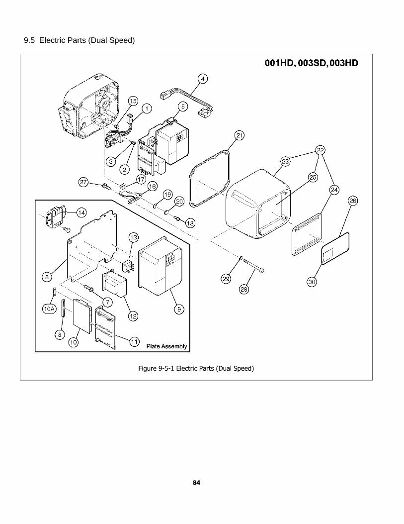
84
9.5 Electric Parts (Dual Speed)
Figure 9-5-1 Electric Parts (Dual Speed)
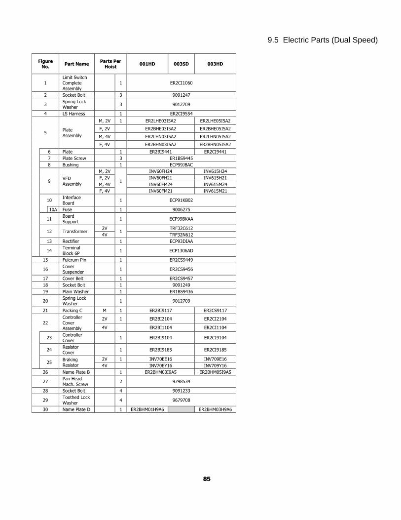
85
9.5 Electric Parts (Dual Speed)
Figure No.
Part Name Parts Per
Hoist 001HD 003SD 003HD
1 Limit Switch Complete
Assembly
1 ER2CI1060
2 Socket Bolt 3 9091247
3 Spring Lock Washer
3 9012709
4 LS Harness 1 ER2CI9554
5 Plate
Assembly
M, 2V 1 ER2LHE03I5A2 ER2LHE05I5A2
F, 2V ER2BHE03I5A2 ER2BHE05I5A2
M, 4V ER2LHN03I5A2 ER2LHN05I5A2
F, 4V ER2BHN03I5A2 ER2BHN05I5A2
6 Plate 1 ER2BI9441 ER2CI9441
7 Plate Screw 3 ER1BS9445
8 Bushing 1 ECP99JBAC
9 VFD Assembly
M, 2V
1
INV60FH24 INV615H24
F, 2V INV60FH21 INV615H21
M, 4V INV60FM24 INV615M24
F, 4V INV60FM21 INV615M21
10 Interface
Board 1 ECP91KB02
10A Fuse 1 9006275
11 Board
Support 1 ECP99BKAA
12 Transformer 2V
1 TRF32C612
4V TRF32N612
13 Rectifier 1 ECP93DIAA
14 Terminal
Block 6P 1 ECP1306AD
15 Fulcrum Pin 1 ER2CS9449
16 Cover Suspender
1 ER2CS9456
17 Cover Belt 1 ER2CS9457
18 Socket Bolt 1 9091249
19 Plain Washer 1 ER1BS9436
20 Spring Lock Washer
1 9012709
21 Packing C M 1 ER2BI9117 ER2CS9117
22 Controller
Cover Assembly
2V 1 ER2BI2104 ER2CI2104
4V ER2BI1104 ER2CI1104
23 Controller Cover
1 ER2BI9104 ER2CI9104
24 Resistor
Cover 1 ER2BI9185 ER2CI9185
25 Braking Resistor
2V 1 INV70EE16 INV709E16
4V INV70EY16 INV709Y16
26 Name Plate B 1 ER2BHM03I9A5 ER2BHM05I9A5
27 Pan Head
Mach. Screw 2 9798534
28 Socket Bolt 4 9091233
29 Toothed Lock
Washer 4 9679708
30 Name Plate D 1 ER2BHM01H9A6 ER2BHM03H9A6
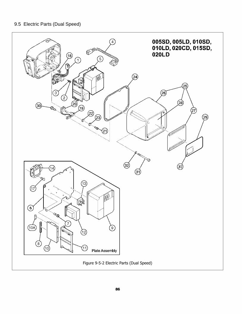
86
9.5 Electric Parts (Dual Speed)
Figure 9-5-2 Electric Parts (Dual Speed)
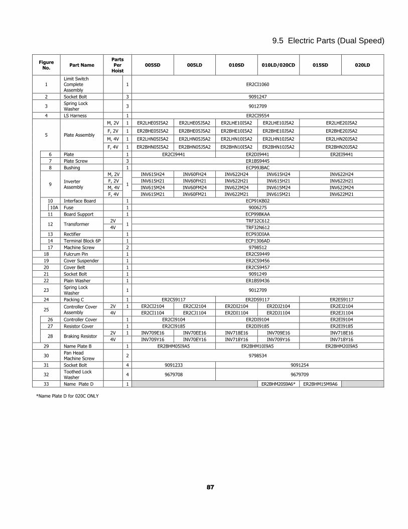
87
9.5 Electric Parts (Dual Speed)
Figure No.
Part Name Parts Per
Hoist
005SD 005LD 010SD 010LD/020CD 015SD 020LD
1 Limit Switch Complete
Assembly
1 ER2CI1060
2 Socket Bolt 3 9091247
3 Spring Lock Washer
3 9012709
4 LS Harness 1 ER2CI9554
5 Plate Assembly
M, 2V 1 ER2LHE05I5A2 ER2LHE05J5A2 ER2LHE10I5A2 ER2LHE10J5A2 ER2LHE20J5A2
F, 2V 1 ER2BHE05I5A2 ER2BHE05J5A2 ER2BHE10I5A2 ER2BHE10J5A2 ER2BHE20J5A2
M, 4V 1 ER2LHN05I5A2 ER2LHN05J5A2 ER2LHN10I5A2 ER2LHN10J5A2 ER2LHN20J5A2
F, 4V 1 ER2BHN05I5A2 ER2BHN05J5A2 ER2BHN10I5A2 ER2BHN10J5A2 ER2BHN20J5A2
6 Plate 1 ER2CI9441 ER2DI9441 ER2EI9441
7 Plate Screw 3 ER1BS9445
8 Bushing 1 ECP99JBAC
9 Inverter Assembly
M, 2V
1
INV615H24 INV60FH24 INV622H24 INV615H24 INV622H24
F, 2V INV615H21 INV60FH21 INV622H21 INV615H21 INV622H21
M, 4V INV615M24 INV60FM24 INV622M24 INV615M24 INV622M24
F, 4V INV615M21 INV60FM21 INV622M21 INV615M21 INV622M21
10 Interface Board 1 ECP91KB02
10A Fuse 1 9006275
11 Board Support 1 ECP99BKAA
12 Transformer 2V
1 TRF32C612
4V TRF32N612
13 Rectifier 1 ECP93DIAA
14 Terminal Block 6P 1 ECP1306AD
17 Machine Screw 2 9798512
18 Fulcrum Pin 1 ER2CS9449
19 Cover Suspender 1 ER2CS9456
20 Cover Belt 1 ER2CS9457
21 Socket Bolt 1 9091249
22 Plain Washer 1 ER1BS9436
23 Spring Lock
Washer 1 9012709
24 Packing C 1 ER2CS9117 ER2DS9117 ER2ES9117
25 Controller Cover
Assembly
2V 1 ER2CI2104 ER2CJ2104 ER2DI2104 ER2DJ2104 ER2EJ2104
4V ER2CI1104 ER2CJ1104 ER2DI1104 ER2DJ1104 ER2EJ1104
26 Controller Cover 1 ER2CI9104 ER2DI9104 ER2EI9104
27 Resistor Cover 1 ER2CI9185 ER2DI9185 ER2EI9185
28 Braking Resistor 2V 1 INV709E16 INV70EE16 INV718E16 INV709E16 INV718E16
4V INV709Y16 INV70EY16 INV718Y16 INV709Y16 INV718Y16
29 Name Plate B 1 ER2BHM05I9A5 ER2BHM10I9A5 ER2BHM20I9A5
30 Pan Head Machine Screw
2 9798534
31 Socket Bolt 4 9091233 9091254
32 Toothed Lock Washer
4 9679708 9679709
33 Name Plate D 1 ER2BHM20S9A6* ER2BHM15M9A6
*Name Plate D for 020C ONLY
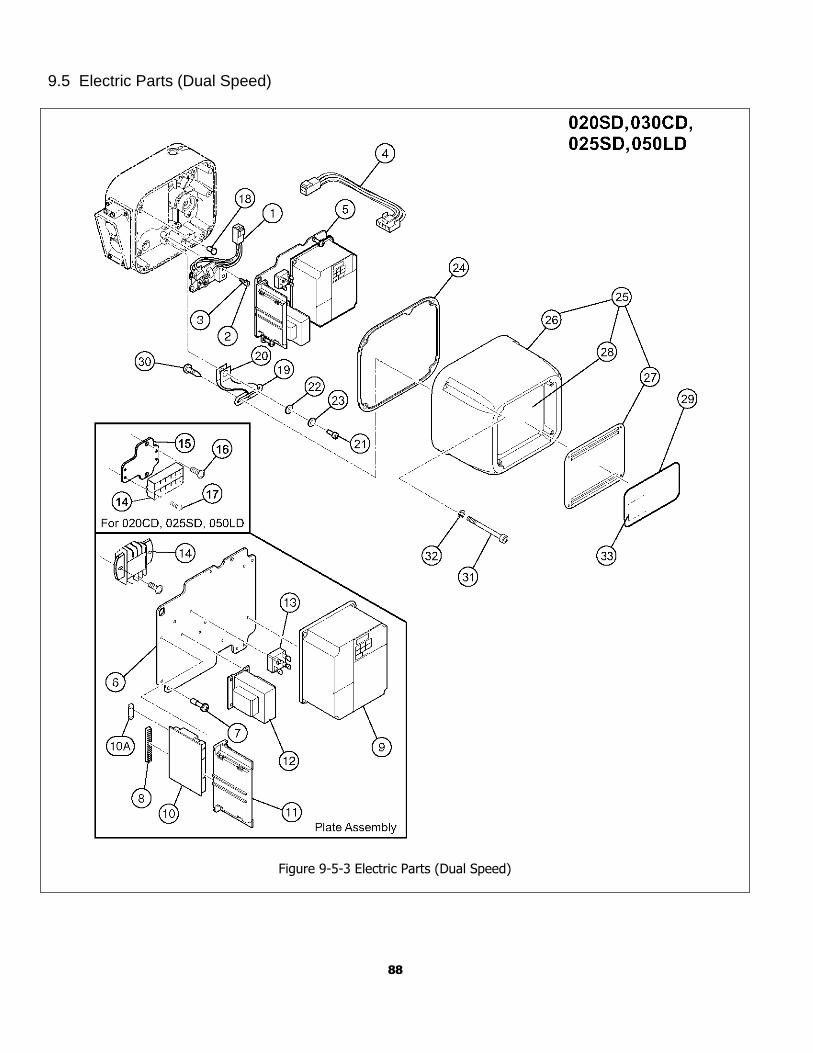
88
9.5 Electric Parts (Dual Speed)
Figure 9-5-3 Electric Parts (Dual Speed)
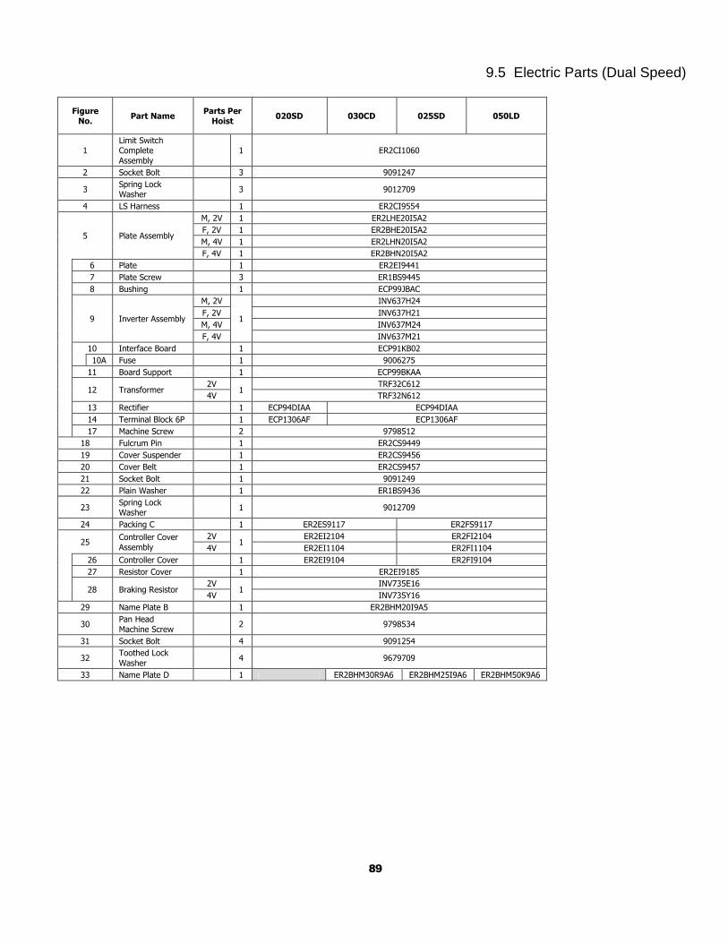
89
9.5 Electric Parts (Dual Speed)
Figure No.
Part Name Parts Per
Hoist 020SD 030CD 025SD 050LD
1 Limit Switch Complete
Assembly
1 ER2CI1060
2 Socket Bolt 3 9091247
3 Spring Lock Washer
3 9012709
4 LS Harness 1 ER2CI9554
5 Plate Assembly
M, 2V 1 ER2LHE20I5A2
F, 2V 1 ER2BHE20I5A2
M, 4V 1 ER2LHN20I5A2
F, 4V 1 ER2BHN20I5A2
6 Plate 1 ER2EI9441
7 Plate Screw 3 ER1BS9445
8 Bushing 1 ECP99JBAC
9 Inverter Assembly
M, 2V
1
INV637H24
F, 2V INV637H21
M, 4V INV637M24
F, 4V INV637M21
10 Interface Board 1 ECP91KB02
10A Fuse 1 9006275
11 Board Support 1 ECP99BKAA
12 Transformer 2V
1 TRF32C612
4V TRF32N612
13 Rectifier 1 ECP94DIAA ECP94DIAA
14 Terminal Block 6P 1 ECP1306AF ECP1306AF
17 Machine Screw 2 9798512
18 Fulcrum Pin 1 ER2CS9449
19 Cover Suspender 1 ER2CS9456
20 Cover Belt 1 ER2CS9457
21 Socket Bolt 1 9091249
22 Plain Washer 1 ER1BS9436
23 Spring Lock Washer
1 9012709
24 Packing C 1 ER2ES9117 ER2FS9117
25 Controller Cover
Assembly
2V 1
ER2EI2104 ER2FI2104
4V ER2EI1104 ER2FI1104
26 Controller Cover 1 ER2EI9104 ER2FI9104
27 Resistor Cover 1 ER2EI9185
28 Braking Resistor 2V
1 INV735E16
4V INV735Y16
29 Name Plate B 1 ER2BHM20I9A5
30 Pan Head
Machine Screw 2 9798534
31 Socket Bolt 4 9091254
32 Toothed Lock
Washer 4 9679709
33 Name Plate D 1 ER2BHM30R9A6 ER2BHM25I9A6 ER2BHM50K9A6
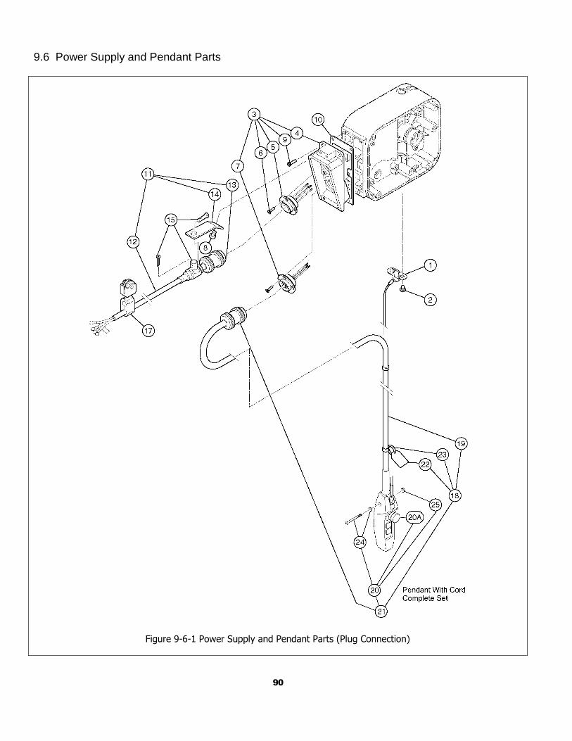
90
9.6 Power Supply and Pendant Parts
Figure 9-6-1 Power Supply and Pendant Parts (Plug Connection)
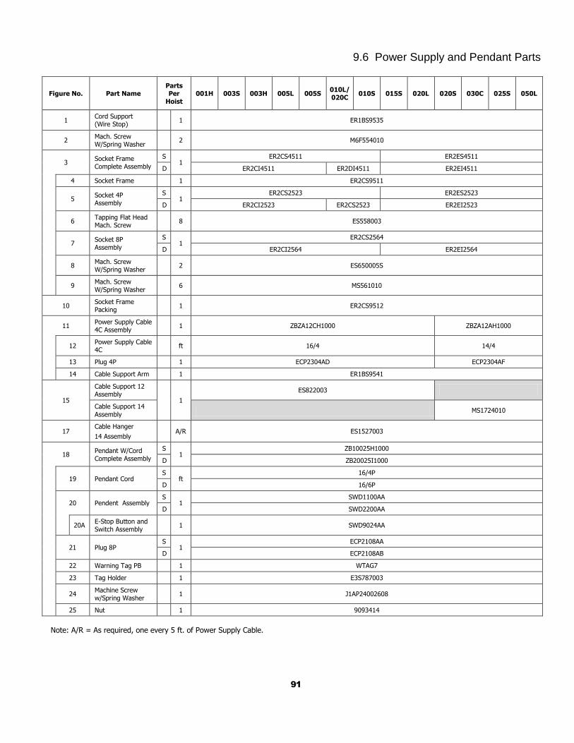
91
9.6 Power Supply and Pendant Parts
Figure No. Part Name Parts Per
Hoist 001H 003S 003H 005L 005S
010L/ 020C
010S 015S 020L 020S 030C 025S 050L
1 Cord Support (Wire Stop)
1 ER1BS9535
2 Mach. Screw W/Spring Washer
2 M6F554010
3 Socket Frame Complete Assembly
S 1
ER2CS4511 ER2ES4511
D ER2CI4511 ER2DI4511 ER2EI4511
4 Socket Frame 1 ER2CS9511
5 Socket 4P Assembly
S 1
ER2CS2523 ER2ES2523
D ER2CI2523 ER2CS2523 ER2EI2523
6 Tapping Flat Head Mach. Screw
8 ES558003
7 Socket 8P Assembly
S 1
ER2CS2564
D ER2CI2564 ER2EI2564
8 Mach. Screw W/Spring Washer
2 ES650005S
9 Mach. Screw W/Spring Washer
6 MS561010
10 Socket Frame Packing
1 ER2CS9512
11 Power Supply Cable 4C Assembly
1 ZBZA12CH1000 ZBZA12AH1000
12 Power Supply Cable 4C
ft 16/4 14/4
13 Plug 4P 1 ECP2304AD ECP2304AF
14 Cable Support Arm 1 ER1BS9541
15
Cable Support 12 Assembly
1
ES822003
Cable Support 14
Assembly MS1724010
17 Cable Hanger
14 Assembly A/R ES1527003
18 Pendant W/Cord Complete Assembly
S 1
ZB10025H1000
D ZB20025I1000
19 Pendant Cord S
ft 16/4P
D 16/6P
20 Pendent Assembly S
1 SWD1100AA
D SWD2200AA
20A E-Stop Button and Switch Assembly
1 SWD9024AA
21 Plug 8P S
1 ECP2108AA
D ECP2108AB
22 Warning Tag PB 1 WTAG7
23 Tag Holder 1 E3S787003
24 Machine Screw w/Spring Washer
1 J1AP24002608
25 Nut 1 9093414
Note: A/R = As required, one every 5 ft. of Power Supply Cable.
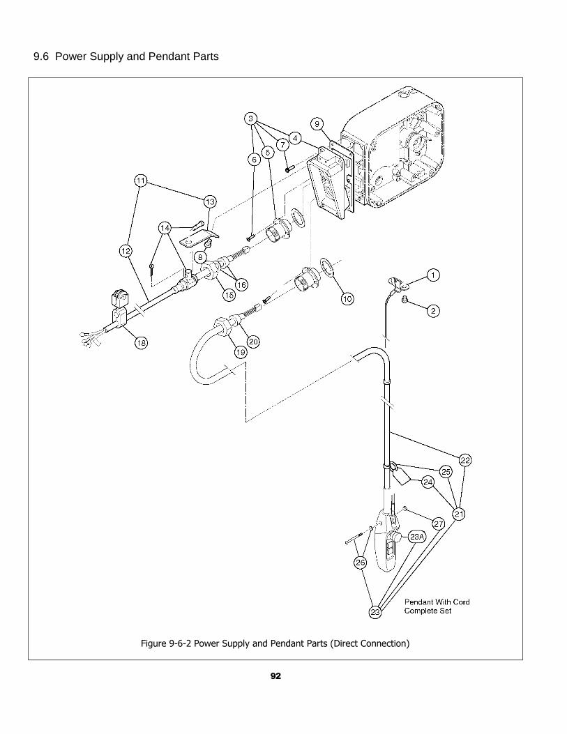
92
9.6 Power Supply and Pendant Parts
Figure 9-6-2 Power Supply and Pendant Parts (Direct Connection)
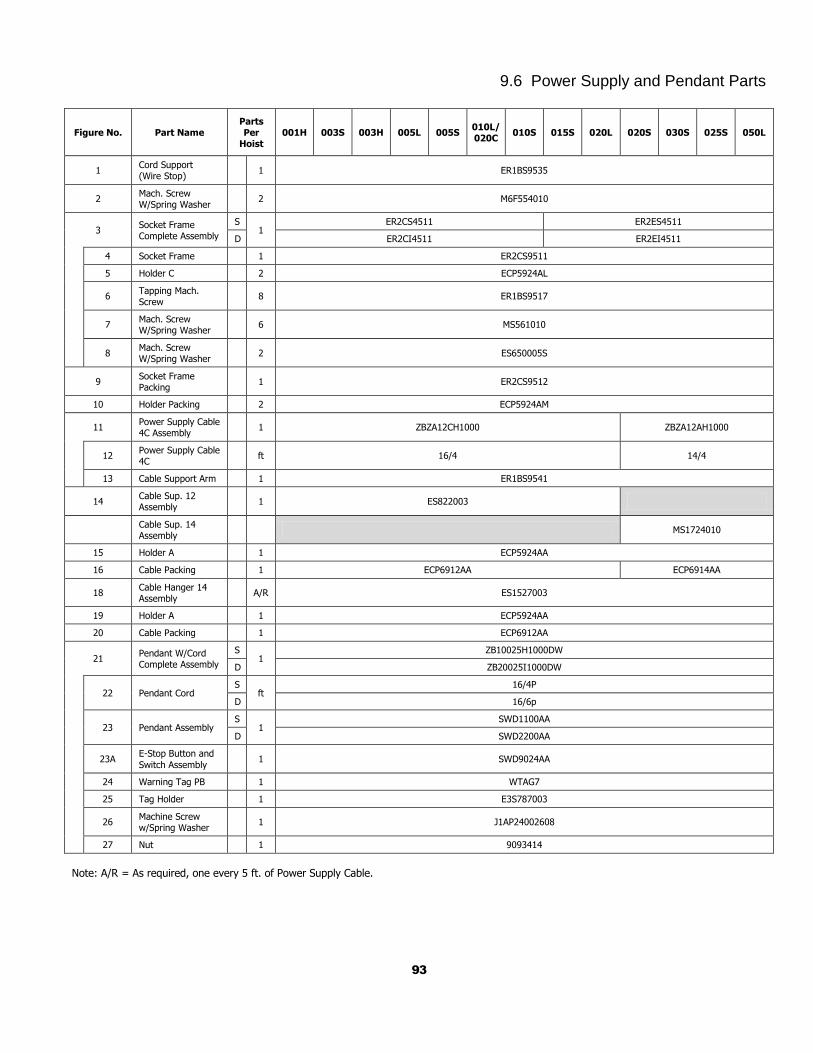
93
9.6 Power Supply and Pendant Parts
Figure No. Part Name Parts Per
Hoist 001H 003S 003H 005L 005S
010L/ 020C
010S 015S 020L 020S 030S 025S 050L
1 Cord Support (Wire Stop)
1 ER1BS9535
2 Mach. Screw W/Spring Washer
2 M6F554010
3 Socket Frame Complete Assembly
S 1
ER2CS4511 ER2ES4511
D ER2CI4511 ER2EI4511
4 Socket Frame 1 ER2CS9511
5 Holder C 2 ECP5924AL
6 Tapping Mach. Screw
8 ER1BS9517
7 Mach. Screw W/Spring Washer
6 MS561010
8 Mach. Screw W/Spring Washer
2 ES650005S
9 Socket Frame Packing
1 ER2CS9512
10 Holder Packing 2 ECP5924AM
11 Power Supply Cable 4C Assembly
1 ZBZA12CH1000 ZBZA12AH1000
12
Power Supply Cable 4C
ft 16/4 14/4
13 Cable Support Arm 1 ER1BS9541
14 Cable Sup. 12 Assembly
1 ES822003
Cable Sup. 14 Assembly
MS1724010
15 Holder A 1 ECP5924AA
16 Cable Packing 1 ECP6912AA ECP6914AA
18 Cable Hanger 14 Assembly
A/R ES1527003
19 Holder A 1 ECP5924AA
20 Cable Packing 1 ECP6912AA
21 Pendant W/Cord Complete Assembly
S 1
ZB10025H1000DW
D ZB20025I1000DW
22 Pendant Cord S
ft 16/4P
D 16/6p
23 Pendant Assembly S
1 SWD1100AA
D SWD2200AA
23A E-Stop Button and
Switch Assembly 1 SWD9024AA
24 Warning Tag PB 1 WTAG7
25 Tag Holder 1 E3S787003
26 Machine Screw w/Spring Washer
1 J1AP24002608
27 Nut 1 9093414
Note: A/R = As required, one every 5 ft. of Power Supply Cable.
94
This Page Intentionally Left Blank

95
This Page Intentionally Left Blank

Harrington Hoists, Inc. 401 West End Avenue Manheim, PA 17545
www.harringtonhoists.com Toll Free: 800-233-3010 Phone: 717-665-2000
Fax: 717-665-2861
ER2OM-ENG


![[PPT]CRANES, HOISTS & TRUCK CRANES - Reagan … · Web viewTitle CRANES, HOISTS & TRUCK CRANES Author blanchtm Last modified by Universal Compression Created Date 2/2/2006 5:23:51](https://img.pdfslide.us/doc/110x75/5af7d12a7f8b9aac248c4b95/pptcranes-hoists-truck-cranes-reagan-viewtitle-cranes-hoists-truck-cranes.jpg)