Embed Size (px)
Citation preview
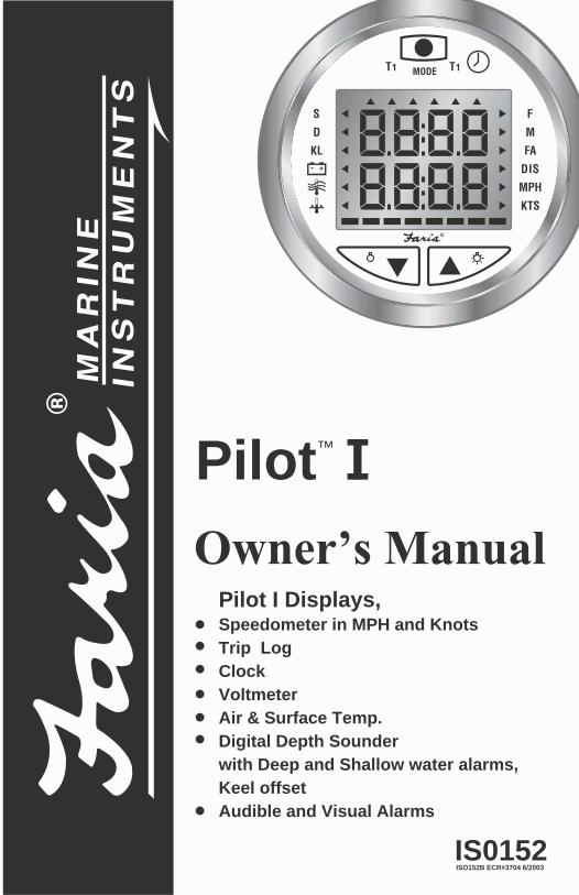
Owner’s Manual
Pilot™ I
ISO152B ECR#3704 6/2003IS0152
Pilot I Displays, Speedometer in MPH and Knots Trip LogClockVoltmeterAir & Surface Temp. Digital Depth Sounderwith Deep and Shallow water alarms,Keel offsetAudible and Visual Alarms
MODE
S
T1 T1
KL
D
F
FA
M
DIS
KTS
MPH
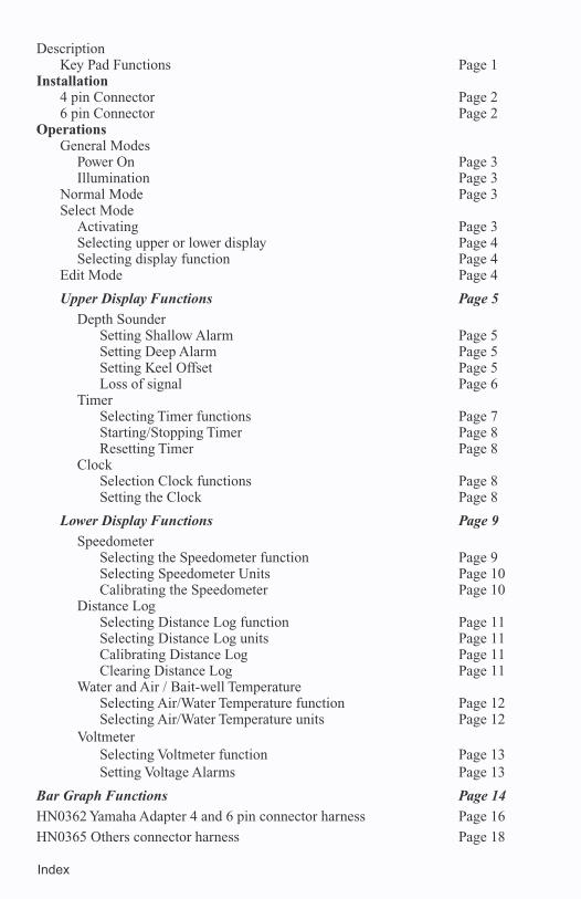
Index
DescriptionKey Pad Functions Page 1
Installation4 pin Connector Page 2 6 pin Connector Page 2
OperationsGeneral Modes
Power On Page 3 Illumination Page 3
Normal Mode Page 3Select Mode
Activating Page 3 Selecting upper or lower display Page 4Selecting display function Page 4
Edit Mode Page 4
Upper Display Functions Page 5
Depth SounderSetting Shallow Alarm Page 5Setting Deep Alarm Page 5Setting Keel Offset Page 5Loss of signal Page 6
TimerSelecting Timer functions Page 7Starting/Stopping Timer Page 8Resetting Timer Page 8
ClockSelection Clock functions Page 8Setting the Clock Page 8
Lower Display Functions Page 9
SpeedometerSelecting the Speedometer function Page 9Selecting Speedometer Units Page 10Calibrating the Speedometer Page 10
Distance LogSelecting Distance Log function Page 11Selecting Distance Log units Page 11Calibrating Distance Log Page 11Clearing Distance Log Page 11
Water and Air / Bait-well Temperature Selecting Air/Water Temperature function Page 12Selecting Air/Water Temperature units Page 12
VoltmeterSelecting Voltmeter function Page 13Setting Voltage Alarms Page 13
Bar Graph Functions Page 14
HN0362 Yamaha Adapter 4 and 6 pin connector harness Page 16
HN0365 Others connector harness Page 18
MODE
S
T1 T1
KL
D
F
FA
M
DIS
KTS
MPH
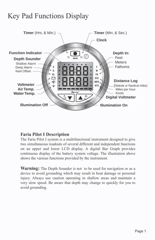
Faria Pilot I DescriptionThe Faria Pilot I system is a multifunctional instrument designed to give two simultaneous readouts of several different and independent functions on an upper and lower LCD display. A digital Bar Graph provides continuous display of the battery system voltage. The illustration above shows the various functions provided by the instrument.
Warning: The Depth Sounder is not to be used for navigation or as a device to avoid grounding which may result in boat damage or personal injury. Always use caution operating in shallow areas and maintain a very slow speed. Be aware that depth may change to quickly for you to avoid grounding.
Page 1
Timer (Hrs. & Min.) Timer (Min. & Sec.)
Clock
Illumination OnIllumination Off
Depth In:Feet
Meters Fathoms
VoltmeterAir Temp.
Water Temp.
Depth SounderShallow Alarm
Deep Alarm Keel Offset
Distance Log(Statute or Nautical miles) Miles per hour Knots
Function Indicator
Digital Voltmeter
Key Pad Functions Display
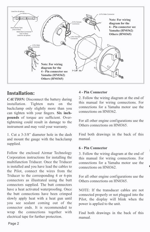
Installation:CAUTION: Disconnect the battery during installation. Tighten nuts on the backclamp only slightly more than you can tighten with your fingers. Six inch-pounds of torque are sufficient. Over-tightening could result in damage to the instrument and may void your warranty.
1. Cut a 3-3/8” diameter hole in the dash and mount the gauge with the backclamp supplied.
Follow the enclosed Airmar Technology Corporation instructions for installing the multifunction Triducer. Once the Triducer is installed and you have lead the cables to the Pilot, connect the wires from the Triducer to the corresponding 4 or 6-pin connectors as illustrated using the butt connectors supplied. The butt connectors have a heat activated waterproofing. Once the butt connections have been crimped slowly apply heat with a heat gun until you see sealant coming out of the connector ends. It is recommended to wrap the connections together with electrical tape for further protection.
4 - Pin Connector
2. Follow the wiring diagram at the end of this manual for wiring connections. For connections for a Yamaha motor use the connections on HN0362.
For all other engine configurations use the Others connections on HN0365.
Find both drawings in the back of this manual.
6 - Pin Connector
3. Follow the wiring diagram at the end of this manual for wiring connections. For connections for a Yamaha motor use the connections on HN0362.
For all other engine configurations use the Others connections on HN0365.
NOTE: If the transducer cables are not connected properly or not plugged into the Pilot, the display will blink when the power is applied to the unit.
Find both drawings in the back of this manual.
Page 2
Used for all splices.Wires
Heat Shrink Tube(red or blue)
Metal Butt Connector(red or blue).
Used for all splices.
6-Pin FemaleConnector
4-Pin FemaleConnector
6-Pin Male Connector
4-Pin MaleConnector
Note: For wiringdiagram for the 4 - Pin connector seeYamaha (HN0362)Others (HN0365)
Note: For wiringdiagram for the 6 - Pin connector seeYamaha (HN0362)Others (HN0365)
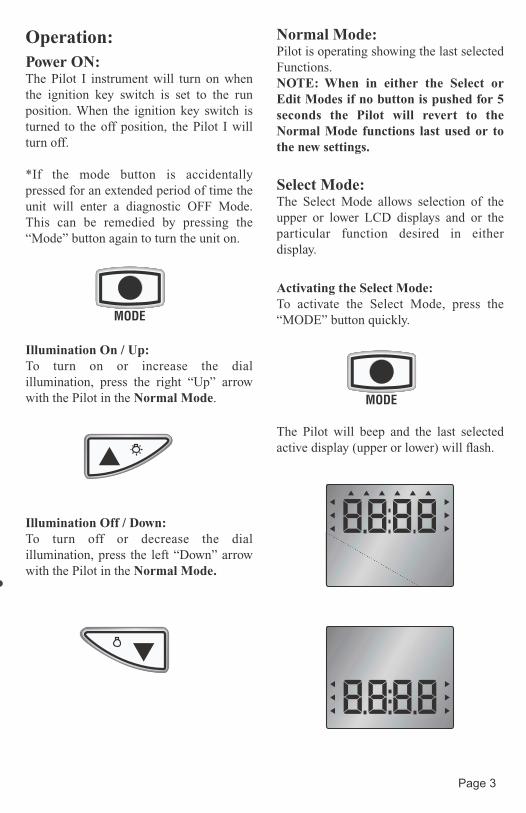
Operation:Power ON:The Pilot I instrument will turn on when the ignition key switch is set to the run position. When the ignition key switch is turned to the off position, the Pilot I will turn off.
*If the mode button is accidentally pressed for an extended period of time the unit will enter a diagnostic OFF Mode. This can be remedied by pressing the “Mode” button again to turn the unit on.
Illumination On / Up:To turn on or increase the dial illumination, press the right “Up” arrow with the Pilot in the Normal Mode.
Illumination Off / Down:To turn off or decrease the dial illumination, press the left “Down” arrow with the Pilot in the Normal Mode.
Normal Mode:Pilot is operating showing the last selected Functions.NOTE: When in either the Select or Edit Modes if no button is pushed for 5 seconds the Pilot will revert to the Normal Mode functions last used or to the new settings.
Select Mode:The Select Mode allows selection of the upper or lower LCD displays and or the particular function desired in either display.
Activating the Select Mode:To activate the Select Mode, press the “MODE” button quickly.
The Pilot will beep and the last selected active display (upper or lower) will flash.
Page 3
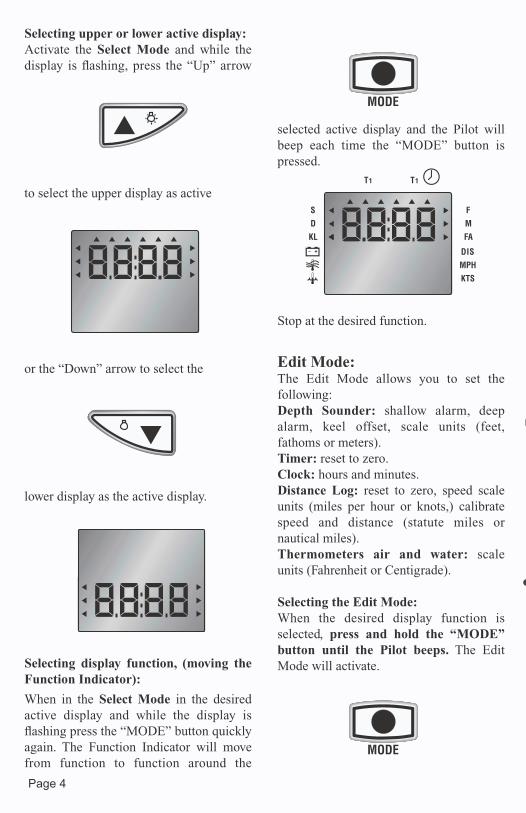
Selecting upper or lower active display:Activate the Select Mode and while the display is flashing, press the “Up” arrow
to select the upper display as active
or the “Down” arrow to select the
lower display as the active display.
Selecting display function, (moving the Function Indicator):
When in the Select Mode in the desired active display and while the display is flashing press the “MODE” button quickly again. The Function Indicator will move from function to function around the
selected active display and the Pilot will beep each time the “MODE” button is pressed.
Stop at the desired function.
Edit Mode:The Edit Mode allows you to set the following:Depth Sounder: shallow alarm, deep alarm, keel offset, scale units (feet, fathoms or meters).Timer: reset to zero. Clock: hours and minutes. Distance Log: reset to zero, speed scale units (miles per hour or knots,) calibrate speed and distance (statute miles or nautical miles).Thermometers air and water: scaleunits (Fahrenheit or Centigrade).
Selecting the Edit Mode:When the desired display function is selected, press and hold the “MODE” button until the Pilot beeps. The Edit Mode will activate.
Page 4
T1 T1
S
KL
D
F
FA
M
DIS
KTS
MPH
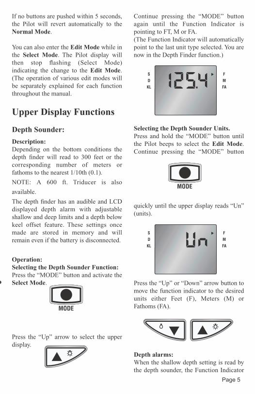
If no buttons are pushed within 5 seconds, the Pilot will revert automatically to the Normal Mode.
You can also enter the Edit Mode while in the Select Mode. The Pilot display will then stop flashing (Select Mode) indicating the change to the Edit Mode.(The operation of various edit modes will be separately explained for each function throughout the manual.
Upper Display Functions
Depth Sounder:
Description:Depending on the bottom conditions the depth finder will read to 300 feet or the corresponding number of meters or fathoms to the nearest 1/10th (0.1).
NOTE: A 600 ft. Triducer is also
available.
The depth finder has an audible and LCD displayed depth alarm with adjustable shallow and deep limits and a depth below keel offset feature. These settings once made are stored in memory and will remain even if the battery is disconnected.
Operation:Selecting the Depth Sounder Function:Press the “MODE” button and activate the Select Mode.
Press the “Up” arrow to select the upper display.
Continue pressing the “MODE” button again until the Function Indicator is pointing to FT, M or FA.(The Function Indicator will automatically point to the last unit type selected. You are now in the Depth Finder function.)
Selecting the Depth Sounder Units.Press and hold the “MODE” button until the Pilot beeps to select the Edit Mode.Continue pressing the “MODE” button
quickly until the upper display reads “Un” (units).
Press the “Up” or “Down” arrow button to move the function indicator to the desired units either Feet (F), Meters (M) or Fathoms (FA).
Depth alarms:When the shallow depth setting is read by the depth sounder, the Function Indicator
Page 5
S
KL
D
F
FA
M
S
KL
D
F
FA
M
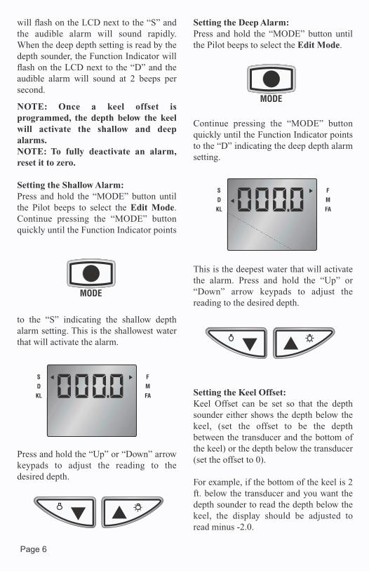
will flash on the LCD next to the “S” and the audible alarm will sound rapidly. When the deep depth setting is read by the depth sounder, the Function Indicator will flash on the LCD next to the “D” and the audible alarm will sound at 2 beeps per second.
NOTE: Once a keel offset is programmed, the depth below the keel will activate the shallow and deep alarms.NOTE: To fully deactivate an alarm, reset it to zero.
Setting the Shallow Alarm:Press and hold the “MODE” button until the Pilot beeps to select the Edit Mode.Continue pressing the “MODE” button quickly until the Function Indicator points
to the “S” indicating the shallow depth alarm setting. This is the shallowest water that will activate the alarm.
Press and hold the “Up” or “Down” arrow keypads to adjust the reading to the desired depth.
Setting the Deep Alarm:Press and hold the “MODE” button until the Pilot beeps to select the Edit Mode.
Continue pressing the “MODE” button quickly until the Function Indicator points to the “D” indicating the deep depth alarm setting.
This is the deepest water that will activate the alarm. Press and hold the “Up” or “Down” arrow keypads to adjust the reading to the desired depth.
Setting the Keel Offset:Keel Offset can be set so that the depth sounder either shows the depth below the keel, (set the offset to be the depth between the transducer and the bottom of the keel) or the depth below the transducer (set the offset to 0).
For example, if the bottom of the keel is 2 ft. below the transducer and you want the depth sounder to read the depth below the keel, the display should be adjusted to read minus -2.0.
S
KL
D
F
FA
M
S
KL
D
F
FA
M
Page 6
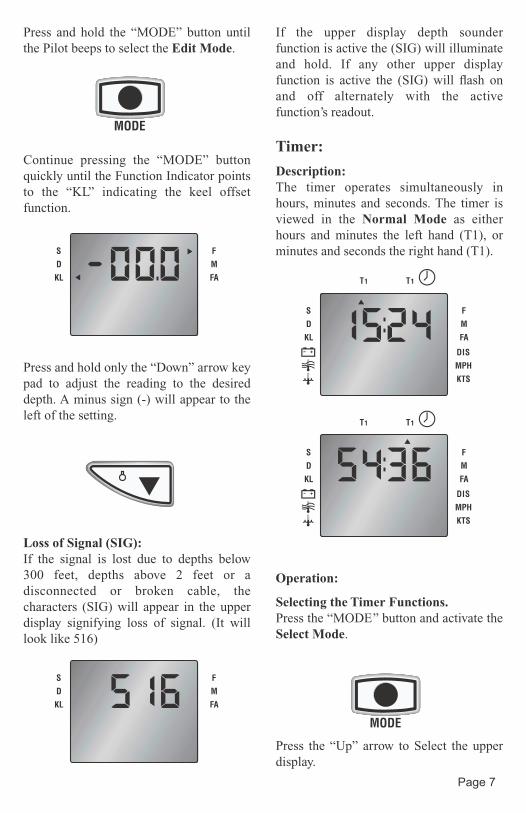
Press and hold the “MODE” button until the Pilot beeps to select the Edit Mode.
Continue pressing the “MODE” button quickly until the Function Indicator points to the “KL” indicating the keel offset function.
Press and hold only the “Down” arrow key pad to adjust the reading to the desired depth. A minus sign (-) will appear to the left of the setting.
Loss of Signal (SIG):If the signal is lost due to depths below 300 feet, depths above 2 feet or a disconnected or broken cable, the characters (SIG) will appear in the upper display signifying loss of signal. (It will look like 516)
If the upper display depth sounder function is active the (SIG) will illuminate and hold. If any other upper display function is active the (SIG) will flash on and off alternately with the active function’s readout.
Timer:
Description:The timer operates simultaneously in hours, minutes and seconds. The timer is viewed in the Normal Mode as either hours and minutes the left hand (T1), or minutes and seconds the right hand (T1).
Operation:
Selecting the Timer Functions.Press the “MODE’’ button and activate the Select Mode.
Press the “Up” arrow to Select the upper display.
S
KL
D
F
FA
M
S
KL
D
F
FA
M
T1 T1
S
KL
D
F
FA
M
DIS
KTS
MPH
T1 T1
S
KL
D
F
FA
M
DIS
KTS
MPH
Page 7
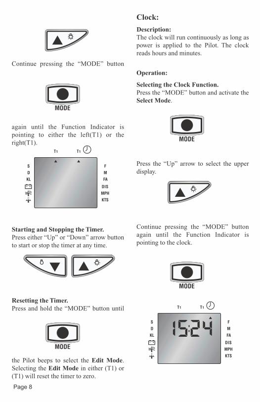
Continue pressing the “MODE” button
again until the Function Indicator is pointing to either the left(T1) or the right(T1).
Starting and Stopping the Timer.Press either “Up” or “Down” arrow button to start or stop the timer at any time.
Resetting the Timer.Press and hold the “MODE” button until
the Pilot beeps to select the Edit Mode.Selecting the Edit Mode in either (T1) or (T1) will reset the timer to zero.
Clock:
Description:The clock will run continuously as long as power is applied to the Pilot. The clock reads hours and minutes.
Operation:
Selecting the Clock Function.Press the “MODE” button and activate the Select Mode.
Press the “Up” arrow to select the upper display.
Continue pressing the “MODE” button again until the Function Indicator is pointing to the clock.
T1 T1
S
KL
D
F
FA
M
DIS
KTS
MPH
T1 T1
S
KL
D
F
FA
M
DIS
KTS
MPH
Page 8
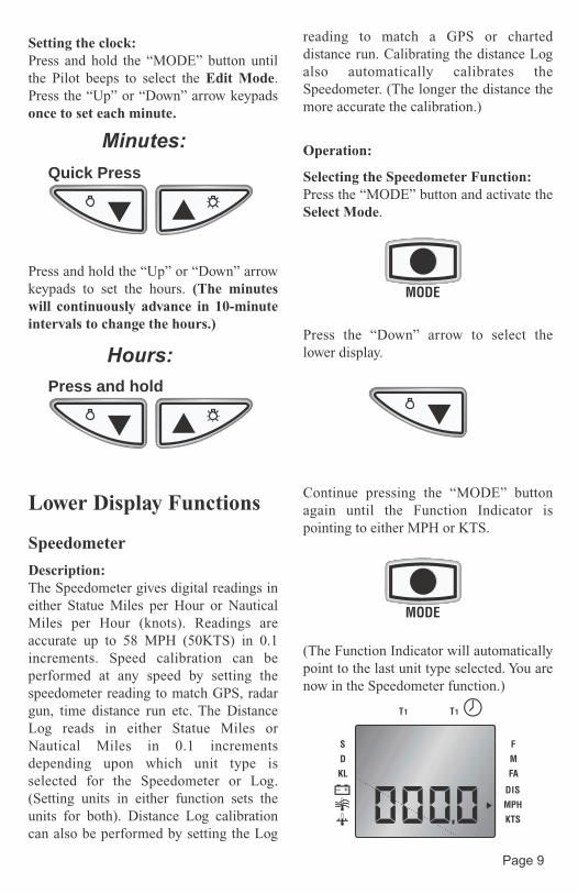
Setting the clock:Press and hold the “MODE” button until the Pilot beeps to select the Edit Mode.Press the “Up” or “Down” arrow keypads once to set each minute.
Press and hold the “Up” or “Down” arrow keypads to set the hours. (The minutes will continuously advance in 10-minute intervals to change the hours.)
Lower Display Functions
Speedometer
Description:The Speedometer gives digital readings in either Statue Miles per Hour or Nautical Miles per Hour (knots). Readings are accurate up to 58 MPH (50KTS) in 0.1 increments. Speed calibration can be performed at any speed by setting the speedometer reading to match GPS, radar gun, time distance run etc. The Distance Log reads in either Statue Miles or Nautical Miles in 0.1 increments depending upon which unit type is selected for the Speedometer or Log. (Setting units in either function sets the units for both). Distance Log calibration can also be performed by setting the Log
reading to match a GPS or charted distance run. Calibrating the distance Log also automatically calibrates the Speedometer. (The longer the distance the more accurate the calibration.)
Operation:
Selecting the Speedometer Function:Press the “MODE” button and activate the Select Mode.
Press the “Down” arrow to select the lower display.
Continue pressing the “MODE” button again until the Function Indicator is pointing to either MPH or KTS.
(The Function Indicator will automatically point to the last unit type selected. You are now in the Speedometer function.)
Quick Press
Press and hold
Minutes:
Hours:
T1 T1
S
KL
D
F
FA
M
DIS
KTS
MPH
Page 9
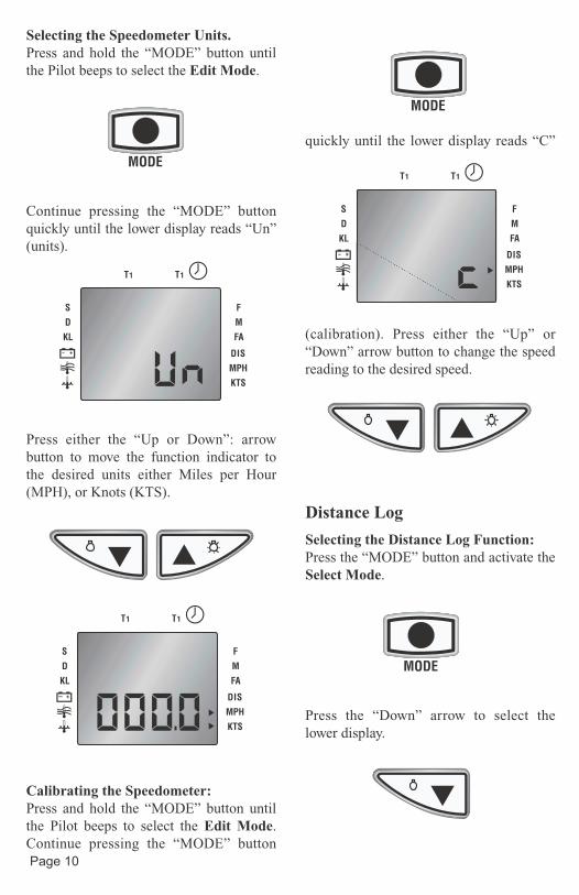
Selecting the Speedometer Units.Press and hold the “MODE” button until the Pilot beeps to select the Edit Mode.
Continue pressing the “MODE” button quickly until the lower display reads “Un” (units).
Press either the “Up or Down”: arrow button to move the function indicator to the desired units either Miles per Hour (MPH), or Knots (KTS).
Calibrating the Speedometer:Press and hold the “MODE” button until the Pilot beeps to select the Edit Mode.Continue pressing the “MODE” button
quickly until the lower display reads “C”
(calibration). Press either the “Up” or “Down” arrow button to change the speed reading to the desired speed.
Distance Log
Selecting the Distance Log Function:Press the “MODE” button and activate the Select Mode.
Press the “Down” arrow to select the lower display.
T1 T1
S
KL
D
F
FA
M
DIS
KTS
MPH
T1 T1
S
KL
D
F
FA
M
DIS
KTS
MPH
T1 T1
S
KL
D
F
FA
M
DIS
KTS
MPH
Page 10
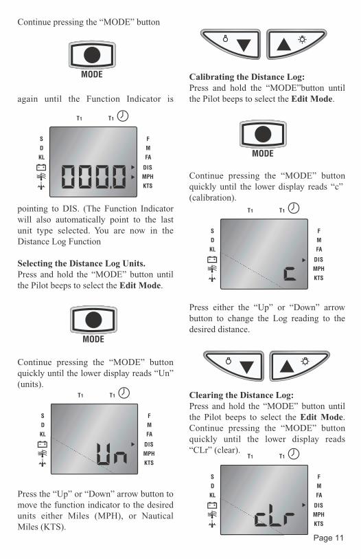
Continue pressing the “MODE” button
again until the Function Indicator is
pointing to DIS. (The Function Indicator will also automatically point to the last unit type selected. You are now in the Distance Log Function
Selecting the Distance Log Units.Press and hold the “MODE” button until the Pilot beeps to select the Edit Mode.
Continue pressing the “MODE” button quickly until the lower display reads “Un” (units).
Press the “Up” or “Down” arrow button to move the function indicator to the desired units either Miles (MPH), or Nautical Miles (KTS).
Calibrating the Distance Log:Press and hold the “MODE”button until the Pilot beeps to select the Edit Mode.
Continue pressing the “MODE” button quickly until the lower display reads “c” (calibration).
Press either the “Up” or “Down” arrow button to change the Log reading to the desired distance.
Clearing the Distance Log:Press and hold the “MODE” button until the Pilot beeps to select the Edit Mode.Continue pressing the “MODE” button quickly until the lower display reads “CLr” (clear).
T1 T1
S
KL
D
F
FA
M
DIS
KTS
MPH
T1 T1
S
KL
D
F
FA
M
DIS
KTS
MPH
T1 T1
S
KL
D
F
FA
M
DIS
KTS
MPH
T1 T1
S
KL
D
F
FA
M
DIS
KTS
MPH
Page 11
T1 T1
S
KL
D
F
FA
M
DIS
KTS
MPH
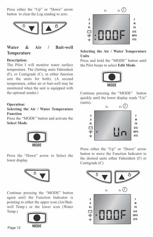
Press either the “Up” or “Down” arrow button to clear the Log reading to zero.
Water & Air / Bait-well Temperature
Description:The Pilot I will monitor water surface temperature. The (Setting units Fahrenheit (F), or Centigrade (C), in either function sets the units for both). (A second temperature, either air or bait-well may be monitored when the unit is equipped with the optional sender.)
Operation:Selecting the Air / Water Temperature FunctionPress the “MODE” button and activate the Select Mode.
Press the “Down” arrow to Select the lower display.
Continue pressing the “MODE” button again until the Function Indicator is pointing to either the upper icon (Air/Bait-well Temp.) or the lower icon (Water Temp.)
Selecting the Air / Water Temperature UnitsPress and hold the “MODE” button until the Pilot beeps to select Edit Mode.
Continue pressing the “MODE” button quickly until the lower display reads “Un” (units).
Press either the “Up” or “Down” arrow button to move the Function Indicator to the desired units either Fahrenheit (F) or Centigrade (C)
T1 T1
S
KL
D
F
FA
M
DIS
KTS
MPH
T1 T1
S
KL
D
F
FA
M
DIS
KTS
MPH
Page 12
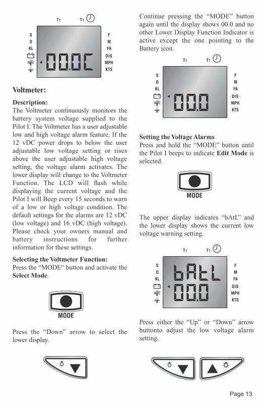
Voltmeter:
Description:The Voltmeter continuously monitors the battery system voltage supplied to the Pilot I. The Voltmeter has a user adjustable low and high voltage alarm feature. If the 12 vDC power drops to below the user adjustable low voltage setting or rises above the user adjustable high voltage setting, the voltage alarm activates. The lower display will change to the Voltmeter Function. The LCD will flash while displaying the current voltage and the Pilot I will Beep every 15 seconds to warn of a low or high voltage condition. The default settings for the alarms are 12 vDC (low voltage) and 16 vDC (high voltage). Please check your owners manual and battery instructions for further information for these settings.
Selecting the Voltmeter Function:Press the “MODE“ button and activate the Select Mode.
Press the “Down” arrow to select the lower display.
Continue pressing the “MODE” button again until the display shows 00.0 and no other Lower Display Function Indicator is active except the one pointing to the Battery icon.
Setting the Voltage AlarmsPress and hold the “MODE” button until the Pilot I beeps to indicate Edit Mode isselected.
The upper display indicates “bAtL” and the lower display shows the current low voltage warning setting.
Press either the “Up” or “Down” arrow buttonto adjust the low voltage alarm setting.
T1 T1
S
KL
D
F
FA
M
DIS
KTS
MPH T1 T1
S
KL
D
F
FA
M
DIS
KTS
MPH
T1 T1
S
KL
D
F
FA
M
DIS
KTS
MPH
Page 13
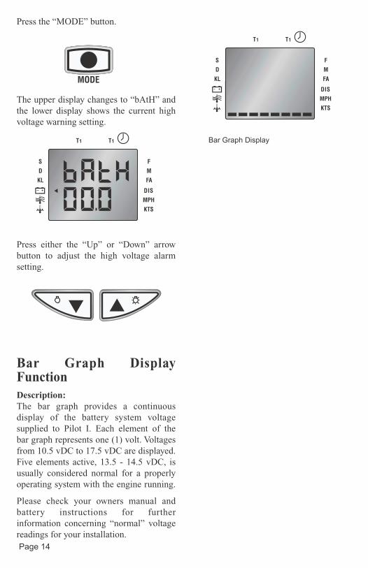
Press the “MODE” button.
The upper display changes to “bAtH” and the lower display shows the current high voltage warning setting.
Press either the “Up” or “Down” arrow button to adjust the high voltage alarm setting.
Bar Graph Display FunctionDescription:The bar graph provides a continuous display of the battery system voltage supplied to Pilot I. Each element of the bar graph represents one (1) volt. Voltages from 10.5 vDC to 17.5 vDC are displayed. Five elements active, 13.5 - 14.5 vDC, is usually considered normal for a properly operating system with the engine running.
Please check your owners manual and battery instructions for further information concerning “normal” voltage readings for your installation.
T1 T1
S
KL
D
F
FA
M
DIS
KTS
MPH
T1 T1
S
KL
D
F
FA
M
DIS
KTS
MPH
Bar Graph Display
Page 14

Page 15
This page left blank intentionally.
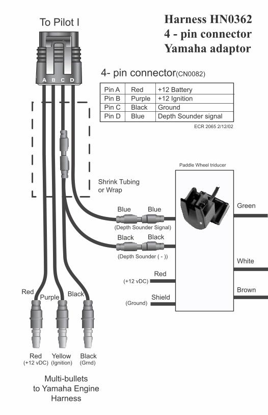
Harness HN0362 4 - pin connectorYamaha adaptor
4- pin connector(CN0082)
Multi-bullets
to Yamaha Engine
Harness
BlackYellowRed
RedPurple
Black
Pin A Red +12 Battery
Pin B Purple +12 Ignition
Pin C Black Ground
Pin D Blue Depth Sounder signal
ECR 2065 2/12/02
(+12 vDC) (Ignition) (Grnd)
To Pilot I
Shrink Tubing
or Wrap
Blue
Black
Blue
Black
(Depth Sounder ( - ))
(Depth Sounder Signal)
Red
Shield
Green
White
Brown
(+12 vDC)
(Ground)
Paddle Wheel triducer
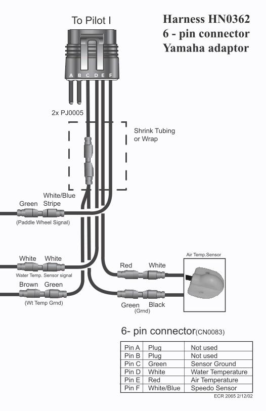
Harness HN0362 6 - pin connectorYamaha adaptor
Red
Green
Green
6- pin connector(CN0083)
Pin A Plug Not used
Pin B Plug Not used
Pin C Green Sensor Ground
Pin D White Water Temperature
Pin E Red Air Temperature
Pin F White/Blue Speedo SensorECR 2065 2/12/02
To Pilot I
Shrink Tubing
or Wrap
Water Temp. Sensor signal
White
Green
White White
Brown
Black
White/Blue
Stripe
Air Temp.Sensor
2x PJ0005
(Paddle Wheel Signal)
(Grnd)
(Wt Temp Grnd)
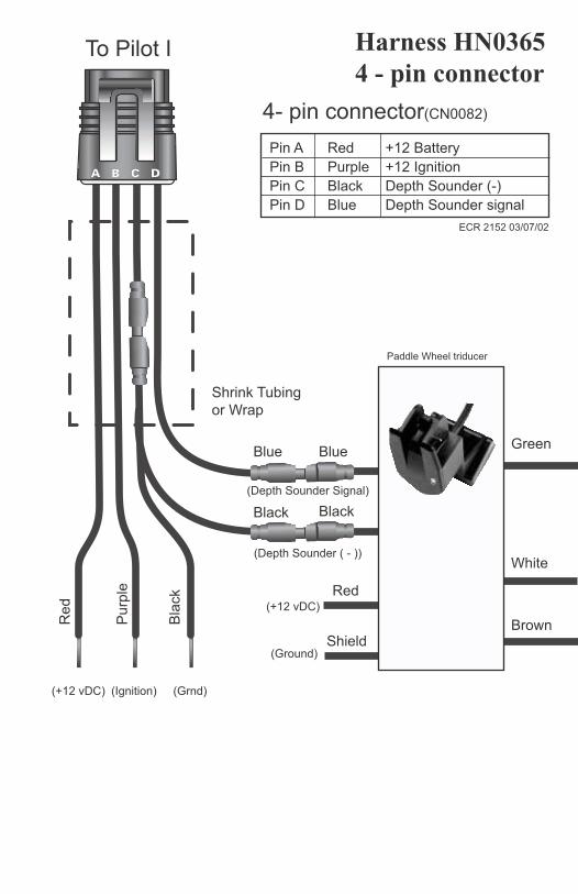
Harness HN0365 4 - pin connector
4- pin connector(CN0082)
To Pilot I
Shrink Tubing
or Wrap
Blue
Re
d
Pu
rple
Bla
ck
Black
Blue
Pin A Red +12 Battery
Pin B Purple +12 Ignition
Pin C Black Depth Sounder (-)
Pin D Blue Depth Sounder signal
Black
ECR 2152 03/07/02
(+12 vDC) (Ignition) (Grnd)
(Depth Sounder ( - ))
(Depth Sounder Signal)
Red
Shield
Green
White
Brown
(+12 vDC)
(Ground)
Paddle Wheel triducer
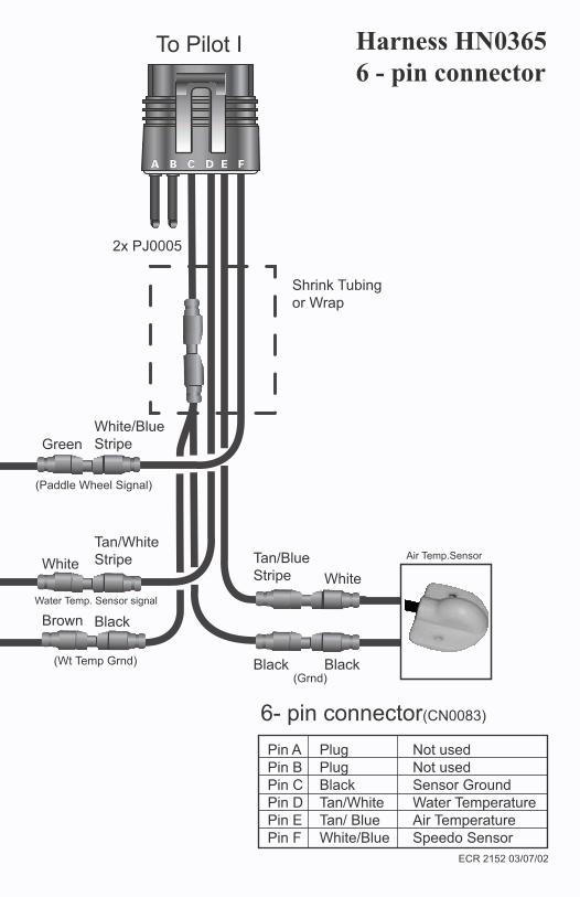
Harness HN0365 6 - pin connector
To Pilot I
Shrink Tubing
or Wrap
Water Temp. Sensor signal
Tan/Blue
Stripe White
Green
Tan/White
StripeWhite
Brown Black
Black Black
White/Blue
Stripe
6- pin connector(CN0083)
Pin A Plug Not used
Pin B Plug Not used
Pin C Black Sensor Ground
Pin D Tan/White Water Temperature
Pin E Tan/ Blue Air Temperature
Pin F White/Blue Speedo Sensor
Air Temp.Sensor
2x PJ0005
ECR 2152 03/07/02
(Paddle Wheel Signal)
(Grnd)
(Wt Temp Grnd)

NOTES

Copyright 2003 by the Thomas G. Faria Corporation, Uncasville CT No part of this publication may by reproduced in any form, in an electronic retrieval system or otherwise, withoutthe prior written permission of the company.