Embed Size (px)
Citation preview
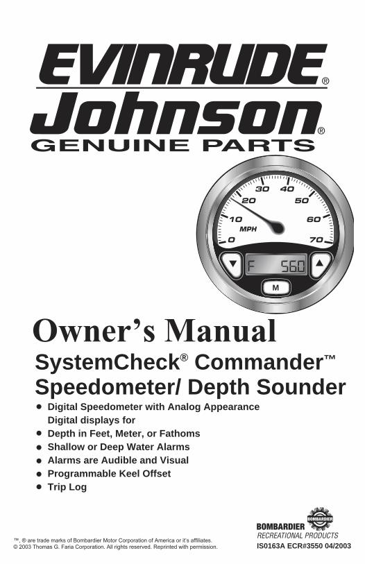
Digital Speedometer with Analog AppearanceDigital displays forDepth in Feet, Meter, or FathomsShallow or Deep Water AlarmsAlarms are Audible and VisualProgrammable Keel OffsetTrip Log
M
IS0163A ECR#3550 04/2003
SystemCheck® Commander™
Speedometer/ Depth Sounder
Owner’s Manual
™, ® are trade marks of Bombardier Motor Corporation of America or it’s affiliates.© 2003 Thomas G. Faria Corporation. All rights reserved. Reprinted with permission.
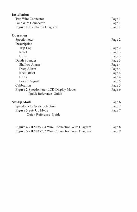
Installation Two Wire Connector Page 1 Four Wire Connector Page 1 Figure 1 Installation Diagram Page 1
Operation Speedometer Page 2 Description Trip Log Page 2 Reset Page 3 Units Page 3 Depth Sounder Page 3 Shallow Alarm Page 4 Deep Alarm Page 4 Keel Offset Page 4 Units Page 4 Loss of Signal Page 5 Calibration Page 5 Figure 2 Speedometer LCD Display Modes Page 6 Quick Reference Guide
Set-Up Mode Page 6 Speedometer Scale Selection Page 7 Figure 3 Set- Up Mode Page 7 Quick Reference Guide
Figure 4 - HN0353, 4 Wire Connection Wire Diagram Page 8 Figure 5 - HN0357, 2 Wire Connection Wire Diagram Page 9
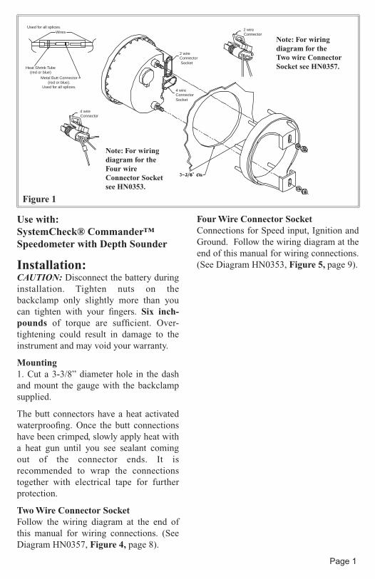
Use with: SystemCheck® Commander™ Speedometer with Depth Sounder
Installation:CAUTION: Disconnect the battery during installation. Tighten nuts on the backclamp only slightly more than you can tighten with your fingers. Six inch-pounds of torque are sufficient. Over-tightening could result in damage to the instrument and may void your warranty.
Mounting1. Cut a 3-3/8” diameter hole in the dash and mount the gauge with the backclamp supplied.
The butt connectors have a heat activated waterproofing. Once the butt connections have been crimped, slowly apply heat with a heat gun until you see sealant coming out of the connector ends. It is recommended to wrap the connections together with electrical tape for further protection.
Two Wire Connector SocketFollow the wiring diagram at the end of this manual for wiring connections. (See Diagram HN0357, Figure 4, page 8).
Four Wire Connector SocketConnections for Speed input, Ignition and Ground. Follow the wiring diagram at the end of this manual for wiring connections. (See Diagram HN0353, Figure 5, page 9).
Used for all splices.Wires
Heat Shrink Tube(red or blue)
Metal Butt Connector(red or blue).
Used for all splices.
2 wireConnector Socket
4 wireConnectorSocket
4 wireConnector
2 wireConnector
Note: For wiringdiagram for the Two wire ConnectorSocket see HN0357.
Note: For wiringdiagram for the Four wireConnector Socket see HN0353.
Page 1
Figure 1
OperationSpeedometerThe speedometer is a digital instrument with the appearance of an analog instrument. The speedometer is designed to be operated from a “paddle wheel” sensor. A microprocessor controlled stepper motor moves the pointer to display boat speed using a linear dial.
The microprocessor and stepper motor provide excellent accuracy. Variations in the operation of the “paddle wheel” sensor are however fairly common. These variations may be caused by the mounting location of the “paddle wheel” on the hull, which affects water flow characteristics, or turbulence and air bubbles in the area of the “paddle wheel”. Therefore, calibration of the speedometer may be required and is easily accomplished by using the Trip Log display or the pointer.
DescriptionThe SystemCheck® Commander™ Speedometer has three push buttons;
The “Mode” button is used to change the function of the LCD display and to access sub menus and adjustable settings. The “Down” and “Up” buttons are used to modify the settings.
In normal operation mode, pressing the “Mode” button for a short period of time causes the display to cycle between the Depth Sounder display and the Trip Log
display. Pressing and holding the “Mode” button causes the display to change to the “settings” sub menus (see Figure 2, page 6).
When the settings menus have been selected, pressing the “Mode” button for a short period of time causes the display to cycle through the setting options. Within each setting selection, pressing the “Down” and “Up” buttons causes the affected setting to change. The microprocessor will automatically record the new settings as you adjust them.
When in a setting menu, pressing and holding the “Mode” button returns to the main function.
Trip Log
The Trip Log is similar to the trip odometer in an automobile. The distance traveled, as recorded by the speedometer “paddle wheel”, is displayed.
The Trip Log may be reset to zero, the units of measure changed, or the
M Mode Button
Down Button
UpButton
Page 2
Miles
Nautical Miles
calibration adjusted using the sub menus.
Pressing and holding the “Mode” button while the Trip Log is displayed will change the display to the “settings” menu (see Figure 2, page 6).
Trip Log “Settings” MenuThere are three items in the Trip Log “Settings” Menu: Reset, Units, and Calibration. Briefly pressing the “Mode” button cycles through the menu items.
The microprocessor will automatically record the new settings as you adjust them.
Reset
Pressing the “Up” and “Down” button resets the Trip Log to zero.
Units
Pressing the “Up” or “Down” button cycles the units of measurement for the Trip Log between miles (MI) and nautical
miles (NM).
Calibration
This menu item is used to simultaneously adjust the calibration of the Speedometer and the Trip Log. Two methods of calibration are possible. These methods will discussed in the Calibration Section.
Depth SounderThe Depth Sounder displays the depth of the water under the boat.
The depth can be displayed in feet, meters, or fathoms. Audible and visual alarms can be set to warn of shallow or deep water conditions. A “keel offset” setting allows the operator to adjust for the difference in the location of the Depth Sounder transducer compared to the deepest part of the boat’s hull. The various settings are accessed by pressing and holding the “Mode” button while the Depth Sounder is displayed (see Figure 2, page 6).
Page 3
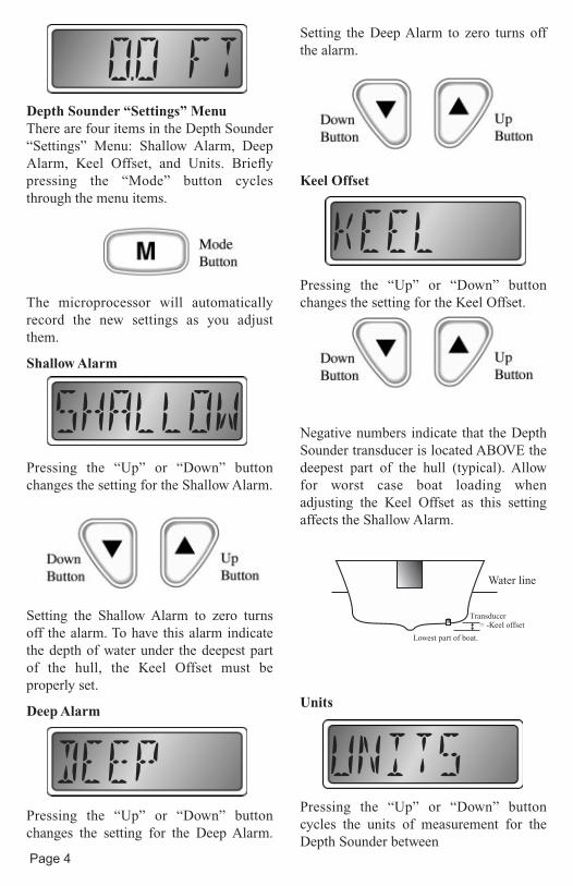
Lowest part of boat.
Transducer= -Keel offset
Water line
Depth Sounder “Settings” MenuThere are four items in the Depth Sounder “Settings” Menu: Shallow Alarm, Deep Alarm, Keel Offset, and Units. Briefly pressing the “Mode” button cycles through the menu items.
The microprocessor will automatically record the new settings as you adjust them.
Shallow Alarm
Pressing the “Up” or “Down” button changes the setting for the Shallow Alarm.
Setting the Shallow Alarm to zero turns off the alarm. To have this alarm indicate the depth of water under the deepest part of the hull, the Keel Offset must be properly set.
Deep Alarm
Pressing the “Up” or “Down” button changes the setting for the Deep Alarm.
Setting the Deep Alarm to zero turns off the alarm.
Keel Offset
Pressing the “Up” or “Down” button changes the setting for the Keel Offset.
Negative numbers indicate that the Depth Sounder transducer is located ABOVE the deepest part of the hull (typical). Allow for worst case boat loading when adjusting the Keel Offset as this setting affects the Shallow Alarm.
Units
Pressing the “Up” or “Down” button cycles the units of measurement for the Depth Sounder between
Page 4
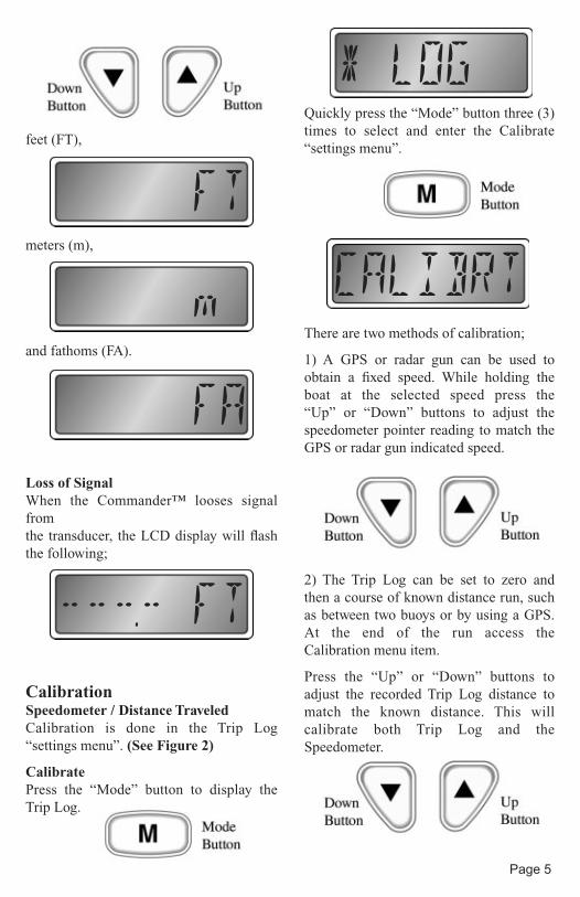
feet (FT),
meters (m),
and fathoms (FA).
Loss of SignalWhen the Commander™ looses signal fromthe transducer, the LCD display will flash the following;
CalibrationSpeedometer / Distance TraveledCalibration is done in the Trip Log “settings menu”. (See Figure 2)
CalibratePress the “Mode” button to display the Trip Log.
Quickly press the “Mode” button three (3) times to select and enter the Calibrate “settings menu”.
There are two methods of calibration;
1) A GPS or radar gun can be used to obtain a fixed speed. While holding the boat at the selected speed press the “Up” or “Down” buttons to adjust the speedometer pointer reading to match the GPS or radar gun indicated speed.
2) The Trip Log can be set to zero and then a course of known distance run, such as between two buoys or by using a GPS. At the end of the run access the Calibration menu item.
Press the “Up” or “Down” buttons to adjust the recorded Trip Log distance to match the known distance. This will calibrate both Trip Log and the Speedometer.
Page 5
-Settings Menus- -Settings Menus-
-
Page 6
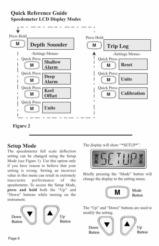
Quick Reference Guide Speedometer LCD Display Modes
Figure 2
Setup ModeThe speedometer full scale deflection setting can be changed using the Setup Mode (see Figure 1). Use this option only if you have reason to believe that your setting is wrong. Setting an incorrect value in this menu can result in extremely inaccurate performance of the speedometer. To access the Setup Mode, press and hold both the “Up” and “Down” buttons while turning on the instrument.
The display will show “*SETUP*”.
Briefly pressing the “Mode” button will change the display to the setting menu.
The “Up” and “Down” buttons are used to modify the setting.
Page 7
Quick Reference Guide Set-Up Mode
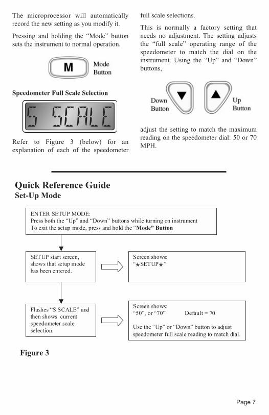
Figure 3
ENTER SETUP MODE:Press both the “Up” and “Down” buttons while turning on instrument To exit the setup mode, press and hold the “Mode” Button
SETUP start screen,shows that setup modehas been entered.
Screen shows:“*SETUP*”
Flashes “S SCALE” andthen shows currentspeedometer scaleselection.
Screen shows:“50”, or “70” Default = 70
Use the “Up” or “Down” button to adjust speedometer full scale reading to match dial.
The microprocessor will automatically record the new setting as you modify it.
Pressing and holding the “Mode” button sets the instrument to normal operation.
Speedometer Full Scale Selection
Refer to Figure 3 (below) for an explanation of each of the speedometer
full scale selections.
This is normally a factory setting that needs no adjustment. The setting adjusts the “full scale” operating range of the speedometer to match the dial on the instrument. Using the “Up” and “Down” buttons,
adjust the setting to match the maximum reading on the speedometer dial: 50 or 70 MPH.
Page 8
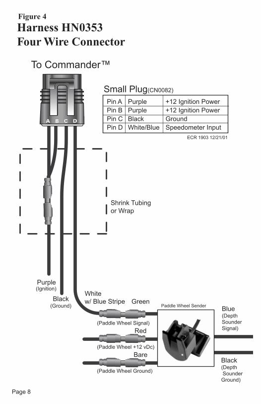
Harness HN0353 Four Wire Connector
Small Plug(CN0082)
To Commander™
Shrink Tubing
or Wrap
Black Green
Red
Bare
Purple
White
w/ Blue Stripe
Pin A Purple +12 Ignition Power
Pin B Purple +12 Ignition Power
Pin C Black Ground
Pin D White/Blue Speedometer Input
ECR 1903 12/21/01
(Ignition)
(Paddle Wheel Signal)
(Paddle Wheel Ground)
(Paddle Wheel +12 vDc)
(Ground)Blue(Depth
Sounder
Signal)
Black(Depth
Sounder
Ground)
Paddle Wheel Sender
Figure 4
Page 9
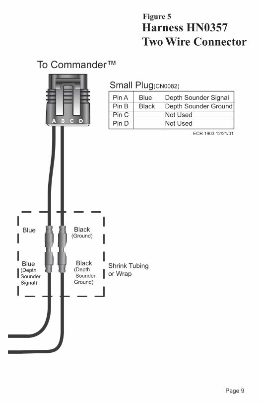
Harness HN0357 Two Wire Connector
Shrink Tubing
or Wrap
(Ground)
Small Plug(CN0082)
To Commander™
Blue
Pin A Blue Depth Sounder Signal
Pin B Black Depth Sounder Ground
Pin C Not Used
Pin D Not Used
ECR 1903 12/21/01
(Depth
Sounder
Signal)
Blue
Black
(Depth
Sounder
Ground)
Black
Figure 5

Notes: